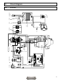
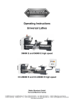
1
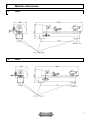
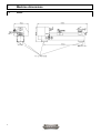
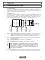
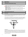
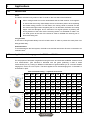
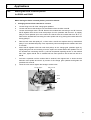
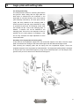
Please read before start-up! Operating instructions Universal Lathes Version of 09/2009 D2000 D2400 D3000 Walter Blombach GmbH Tool and Machine Factory D-42899 Remscheid Am Blaffertsberg 13 Phone: 0049 (2191) 597-0 Fax: 0049 (2191) 597-40 D-54673 Neuerburg WABECO Str. 1-10 Phone: 0049 (6564) 9697-0 Fax: 0049 (6564) 9697-25 www.wabeco-remscheid.de E-Mail: [email protected] E-Mail: [email protected] Dear customer! Congratulations on choosing the WABECO Universal Lathe. We have taken great care in its manufacture and we have given it a thorough quality control test. These operating instructions are to help you to work with it safely and properly. Therefore, please read the respective instructions carefully and pay attention to them. After unpacking the machine please check to see if any kind of damage has occurred during transportation. Any complaints must be made immediately. Complaints made at a later date cannot be accepted. If you have any questions or need any spare parts, please quote the machine number located on the front of the motor (see nameplate). Duplications or copies of this document of any kind, or of exerts, require a written approval by WABECO Disposal of the lathe The transport and protective packagings are made up of the following materials: - corrugated cardboard - polystyrene free of freon - polyethelene foil - non-returnable wooded pallet (untreated) - Euro pallet (deposit) If you have no further need of these articles or do not wish to use them again, please dispose of them at the public recycling facilties. The lathe consists of up to 98% of recyclable materials, i.e. steel, cast iron, aluminium and 2% of chemical materials, e.g. the coating of electrical leads, printed circuits. If you have trouble disposing of these parts in a proper manner, we would be pleased to help you. Upon mutual agreement we will take the complete machine back and dispose of it. However, the costs for transporting the machine to our plant must be at your expense. 2 Index 1. 1.1 1.2 1.3 EC Conformity declaration Machine dimensions D2000 D2400 D3000 4 5 5 5 6 2. Delivery and installation 7 3. Conditions for best results 7 4. Overload protection 8 5. Safety instructions 8 6. 6.1 6.2 6.3 6.4 6.5 6.6 6.7 6.8 Start-up and maintenace Electronical equipment Start-up Maintenance Lubrication Initial cleaning of the machine Headstock Cross support Tailstock 9 9 9 9 10 10 11 11 12 7. 7.1 7.1.1 7.1.2 7.1.3 7.2 Speed regulation Speed selection Speed setting for working with aluminium Speed setting for working with steel Speed setting for working with brass, copper Speed change 13 13 13 13 14 14 8. 8.1 8.2 8.2.1 8.2.2 8.2.3 8.2.4 Applications Longitudinal and transverse turning Thread cutting with automatic feed General note Application of change gears Altering the feeds or thread pitches for D2000, D2400 Altering the feeds or thread pitches for D3000 15 15 16 17 17 19 21 9. Pair of toothed wheels for left-hand thread cutting 22 10. Angle plate with milling table 23 11. Lubrication coolant unit 24 12. Declaration of noise levels 25 13. 13.1 13.2 13.3 13.4 13.5 13.6 13.7 13.8 Drawings and list of parts Headstock Support with motor and protective cover for D2400 und D3000 Lead screw drive for D2000 and D2400 Lead screw drive for D3000 Drive with gear transmission for D2000 Cross support Tailstock Rear bearing with guide rods 26 26 27 28 30 32 34 36 37 13. 13.1 13.2 Circuit diagram Circuit diagram for D2000 and D2400 Circuit diagram for D3000 38 38 39 3 EC – Conformity Declaration Version 07.2010 In the name of the manufacturer Walter Blombach GmbH Tool and Machine Factory based in Remscheid and Neuerburg D-42871 Remscheid D-54673 Neuerburg Postfach 12 01 61 WABECO Str. 1-10 Phone: 0049 (2191) 597-0 Phone: 0049 (6564) 9697-0 Fax: 0049 (2191) 597-40 Fax: 0049 (6564) 9697-25 We hereby declare that the universal milling and drilling machines specified below Universal Lathes Typ: D2000 – D2400 – D3000 meet the following regulation requirements for standard series production - directive for machines 2006/42 EG EMV directive 89/336/EWG In order to meet / implement the requirements of the above mentioned directives, the following applicable and previously published standards have been adhered to: EN ISO 12100-1 EN ISO 12100-2 EN 12840 EN 60204-1 D-54673 Neuerburg ________________________________ City Technical Director 4 1. Machine dimensions 1.1 D2000 1.2 D2400 5 1. Machine dimensions 1.3 D3000 6 2. Delivery and installation The lathes are carefully packed in our factory. Please check the following on delivery: 1. whether the packaging has been damaged and/or: 2. whether the lathe shows signs of damage in transit or if there is any other reason for complaint. In this case we request your immediate notification. Claims made at a later date cannot be accepted. The lathe must be installed on appropriate, plain and firm ground. This would be, for example: a base cabinet such as to be found in our accessories programme a work bench strong enough to carry the weight of the machine without warping with an even surface (see technical data and check with spirit level). a steel plate The lathe must be screwed to the base. Use the 9 mm holes in the machine base. Good results and a minimum of vibration during operation can only be guaranteed if the above mentioned requirements for secure mounting are observed. The machine should be installed in a well lighted area and electrical cables with earthed sockets and O-conductors must be installed close to the machine so that the mains cable is not subject to any tension whatsoever. The mains cable should be such that, for example, by means of a multiple socket, a coolant unit can also be connected. 3. Conditions for best results i Fix the machine to a sturdy, level support. Use sharp processing tools. Adjust speed setting and feed to fit the material and diameter of the tool. The clamping position of the tools is to be as close as possible to the workpiece. Clamp the workpieces tightly and without vibrations. Long pieces are to be supported by the tailstock or a stay. Apply coolant and lubricant for better surface quality (finish) and dimensional accuracy. The clamping surfaces for clamping tools and workpieces must be clean. Grease the machine sufficiently. Use the correct machining tools for removing the material from the workpieces. Set the correct bearing clearances and align guides. 7 4. Overload protection i 5. Wait approx. 1 second after switching off the machine manually or after an automatic switchdown following an overload before switching it on again. This will ensure that the motor is protected effectively in all work situations. Otherwise the machine may not run up again because the electronics relay could did not have enough time to react. Safety Instructions 1. 2. 3. 4. 5. 6. 7. 8. 9. 10. 11. 12. 13. 14. 15. 16. 17. The feed line for the motor must be connected to a sealed contact socket or junction box. (Have the socket or junction box checked by an electrician beforehand; protection against children being able to put into operation). The socket or junction box must be close enough to the equipment, so that the live cable is subjected to no tensile strain whatsoever. When maintenance or cleaning work is done, the machine must be shutdown and the mains plug pulled out. Do not slow down workpieces or chucks by hand or any other objects. Wear safety goggles when working with the machine. Do not remove the chips with the hand. Use corresponding aids (hand brush, hook, paint brush). Always keep the protective hood of the drive closed. The turning tools must be tightly clamped at the correct height and as short as possible. The turning tools must never be replaced when the machine is running. Never leave the clamping chuck key in (even when not in operation). Always pay attention to the clamping width of the lathe chuck. (lathe chucks ∅ max. 40mm, drill chucks max. 100mm ∅). Never take measurements on work pieces during the lathing process (risk of accidents and damage to the measuring gauges) Do not wear loose clothing (ties, shirt sleeves, jewellery etc.). When working between centres, always centre well in order to prevent the workpiece from being slung away. In addition, make sure that the locking screw of the tailstock is tightened. When using the automatic feed always take care that the cross support does not get in contact with the chuck or the tailstock. Never leave the machine alone when in operation. When machining wood, use the lathe centre instead of the lathe chuck to support the work piece. 18. The machine must be secured so that it cannot be switched on by children. Make sure that other people do not operate the machine. 19. Always keep the machine dry. 20. Frequently check the machine for damage. Any damaged parts must be replaced by original parts and are to be fitted by an expert or by us. 8 6. Start-up and Maintenance 6.1 Electronical equipment The lathes are fitted with a main switch with undervoltage release, i.e. this switch must be turned on before turning on the reserving switch. The main switch must also be switched on again following a power failure. i All lathes can only be switched on with closed plexiglass bonnet. When changing the sense of rotation by turning the right-left switch, the switch must remain for 1 sec. on 0-position for the reason that the relay of the potentiometer has enough time to switch. 6.2 Start up i 6.3 Prior to the initial operation, the machine must once more be cleaned with great care and all lubrication points have to be lubricated with grease. Thoroughly oil the cross support, lead screws, guiding rods and spindle sleeve. Check all spindles by hand in order to ensure they run smoothly. Run in the lathe on the lowest speed. A full load to start with must be avoided. Maintenance The working life is vitally dependent upon appropriate care. The lathe needs to be cleaned after every turning job. i In case the lathe is to be installed in a moist cellar room, all bare parts need to be oiled after use to avoid corrosion. All moving parts must constantly lubricated with grease. In case of backlash inside the bearings or inside the guideways of the slides, readjust in time to avoid the bearing or the guideways of the slides being destroyed. 9 6. Start-up and Maintenance 6.4 Lubrication Prior to every putting into operation all lubricating points of the lathe must be lubricated with grease for roller bearings of commercial quality. Both guiding bars have to be greased before every putting into operation. The two dovetail guides of the cross support, the threaded spindles accessible from below, the feed shaft as well as the tailstock sleeve have to be greased with lubricating oil every 100 service hours. When greasing make sure to put the slide of the cross support to its hindmost position while moving the tailstock sleeve to its foremost position. The tailstock spindle is to be greased via the hollow bore in the sleeve. apply grease prior to every putting into operation 6.5 Initial cleaning of the machine Prior to the initial operation all bare parts have to be cleaned by applying petroleum or benzine, because these parts were covered with antirust oil before leaving the factory. 10 6. Start-up and Maintenance 6.6 Headstock The headstock is firmly attached to the guide bars. Inside the headstock, the work spindle is run on two adjustable precision tapered roller bearings. adjustment nut ON -OFF lever for automatic feed If the bearings need to be readjusted, please proceed in the following manner: 1. Loosen the stud bolt in the adjustment nut. The adjustment nut is located at the rear end of the work spindle. 2. Turn the adjustment nut clockwise until the bearings run free of play again (the work spindle can easily be turned by hand). 3. Re-Tighten the stud bolt. i Roller bearings adjusted too tightly become useless after a short period Automatic feed: There is an on-off lever for the automatic feed on the front of the headstock. The machine is delivered with the wheels for feed 0.085 mm/rev. attached. 6.7 Cross support The cross support consists of a longitudinal and a transversal support. It is equipped with ajustable dovetail guides. 11 6. Startup and Maintenance 6.7 Cross support If adjustment becomes necessary, please proceed in the following manner: 1. Loosen the lock nuts. 2. Tighten the readjustment screws by using a socket head wrench until the slides can easily be moved to and fro by means of the crank. 3. Re-tighten the lock nuts after the adjustment. Longitudinal support: The longitudinal support which is mounted to the transversal support is pivotable by 360°. Thus, it is suitable for the turning of tapers. Adjust the position by loosening the two screws located on the outer sides of the transverse support with a 4 mm allen key. The arrow on the transversal support indicates the position of the longitudinal support in degrees. There is a degree scale on the longitudinal support. The distance between two graduation marks represents one degree. Graduated collars: The support spindles are provided with graduation collars with graduation marks used for setting the turning tools. One graduation mark represents a 0.05 mm feed adjustment which corresponds to a 0.1 mm chip removal from the workpiece at the transversal slide and a 0.05 mm chip removal at the longitudinal slide. The hexagon socket screw serves for locking the cross support to the guide bars (e.g. in face turning.) The screw pulls the block at the bottom of the transverse support against the two guide bars. 6.8 Tailstock The tailstock is attached to the guide bars in such a way that it is slidable. It can be be locked in any position by actuating the lower T-handle (4251). It can be separated into barrel and base. By loosening the hexagon bolt (424), the tailstock barrel can be pushed to either side by up to 10 mm and is, therefore, suitable for the machining of slight tapers. After completion of the taper machining, move the tailstock to its home position. The lateral mark indicates the central position of the tailstock. Find out by doing some trial turning if the workpiece is cylindrical and correct the tailstock position if necessary. Solid tailstock sleeve: The solid tailstock sleeve, which is provided with a millimetre scale, is designed in such a way that the lathe centre, drill barrel or chuck are automatically ejected during the backward motion. Tool clamping: An inner taper MT 2 is available for holding the tool. It is integrated in the sleeve. By tightening the upper T-handle (4251), the tailstock sleeve can be clamped easily in any position. The sleeve can be moved axially by the crank (31212) located at the rear end via the threaded spindle. T-handle (4251) for tightening the tailstock crank (31212) to move the tailstock sleeve spanner bolt (424) T-handle (4251) for tightening the tailstock 12 7. Speed regulation 7.1 Speed selection The spindle speed is to be selected according to material type and the diameter of the work piece: Small diameter Large diameter ⇒ ⇒ relatively high speed low speed The cutting speed is the result of rotational speed and diameter. With a known and required cutting speed, the necessary spindle speed can be calculated in the following way: cutting speed (V) x 1000 speed (n) = diameter of workpiece (d) x 3,14 Example: An aluminium workpiece which has a diameter of 20 mm is to be turned with a cutting speed of 100 m/min. 100 x 1,000 100,000 = 20 x 3.14 62.8 = 1592 1/min Now, from those speeds available, the one which is closest to the ideal speed of 1592 1/min. is selected (in our case 1600 1/min.). 7.1.1 7.1.2 Speed setting for working with Aluminium workpiece- Ø approx. r.p.m. cutting speed m/min 10 mm 2300 75 20 mm 1600 100 40 mm 800 100 60 mm 530 100 80 mm 400 100 100 mm 320 100 Speed setting for working with steel workpiece- Ø approx. r.p.m. cutting speed m/min 10 mm 1600 50 20 mm 800 50 40 mm 400 50 60 mm 270 50 80 mm 200 50 100 mm 160 50 13 7. Speed regulation 7.1.3 Speed setting for working with Brass, Copper 7.2 workpiece- Ø approx. r.p.m.. cutting speed m/min 10 mm 2300 80 20 mm 1270 80 40 mm 640 80 60 mm 425 80 80 mm 320 80 100 mm 250 80 Speed change Rotational speed range 45 - 2300 min-1: The rotational speed of the work spindle is infinitely variable between 45 and 400 r.p.m. in the 1st step or in the 2nd step between 200-2300 r.p.m using the potentiometer on the front side of the machine. speed setting at the potentiometer 1. step r.p.m. 2. step r.p.m. 10 45 200 20 105 350 30 175 740 40 260 1050 50 325 1440 60 360 1650 70 400 1860 80 460 2120 90 490 2160 100 500 2300 Rotational speed 45 - 400 r.p.m.: The drive belt must be relocated if the lower speed level with a minimum speed of 45 r.p.m. is required. Proceed as follows: Remove the protective cover and release the drive belt by unscrewing the clamping nut and turning the star handle clockwise until the drive belt can be relocated. Then re-tighten the drive belt in the reverse sequence of steps. rotational speed 45-400 rpm clamping nut star handle potentiometer 14 8. Applications 8.1 Longitudinal and transverse turning Longitudinal turning: In the case of longitudinal turning the tool moves parallel to the axis of the workpiece. For longitudinal rough turning it is recommended to use either a straight or an arcuated turning tool. For finishing it is best to use pointed or wide turning tools. Transverse turning: The maching of the end faces is known as transverse turning. In the case of transverse turning, the turning tool is moved at 90 degrees to the turning axis of the piece being turned. In so doing the cross support is to be locked. The main cutting lip of the turning tool is to be exactly centred, so that no lug remains in the workpiece centre. The arcuated tool is used for transverse turning. 6 1 2 3 4 5 to 1+2: Roughing tools arcuated to the left and/or to the right: By using them a maximum of material is removed in as short a time as possible (without paying attention to the finish on the surface of the work piece). They can be used for longitudinal and transverse turning. to 3: Offset side turning tool: Used for finishing (smooth surface) in the case of longitudinal and transverse turning. to 4: Outside thread turning tool: Used for cutting outside threads. to 5: Parting tool: Used for the cutting of grooves and slicing of workpieces. i When inserting the parting tool No. 5, pay careful attention to the exactness of the centre height of the turning tool. Work on low speed and cool the tool (use soluble oil or emulsion for cooling: serves to lubricate and for the removal of chips.) The parting tool is to be clamped as short as possible and at 90° degrees to the workpiece. to 6: Inside turning tool: Used for the hollowing-out boreholes. Clamp as short as possible in order to avoid vibrations of the turning tool which might otherwise occur (uneven surface). 15 8. Applications 8.1 Longitudinal and transverse turning i For the reason of the force effect at the turning tool take care that the tool is short and tightly clamped. If the lever arm is to long the turning chisel curves and springs back. The cutting part enters uneven into the workpiece and is producing a waved surface. Take care that the turning tool is directed to the centre of the work piece. The height position in the workpiece centre is regulated via the live lathe centre inside the tailstock. The height position of the turning tool is achieved by straight sheet steel. 8.2 Thread cutting with automatic feed 8.2.1 General note The thread cutting tool is a shape turning tool with the profile of the thread to be cut. It is ground according to jigs (diagram 1) and must be adjusted exactly to the workpiece centre as, otherwise, the profile of the thread would be distorted. In order to obtain the correct position of the thread flanks to the axis of the workpiece, the grinding jig is put against the work piece and the turning tool is adjusted in accordance with it (diagram 1). For this purpose the jig is put successively on to both flanks of the turning tool. The feed of the thread cutting tool is effected over the lead screw and must correspond to the thread pitch. Setting the thread cutting tool 90° Change gears: The connection between the feed gear and the lead screw is made by the change gear wheels (optional for D2000, D2000 and D2400). By putting on various combinations of gear wheels it is possible to cut a metric right-hand thread with a pitch of 0.4 mm - 3 mm and an inch-system righthand thread with a pitch of 10Z/1" - 32 Z/1" (see table “table for thread cutting and automatic feed”). The various distances between the gear axes can be adjusted by swiveling the quadrant and by readjusting the quadrant bolts. 16 8. Applications 8.2.1 General note Feed: The feed is switched on by means of the T-handle on the front side of the headstock. i When cutting threads it must be remembered that the feed remains on throughout to ensure that the turning chisel always returns to the same positon when repeating the thread cutting process. For this reason, the turning chisel is cammed out with the transversal support after completing the cut, as otherwise, the flanks and cutting edges could be damaged, and is returned to its original position by altering the turning direction of the motor via the reversing switch. It is advisable to make a 4-5 mm wide groove at the end of the thread in order to facilitate the camming out of the thread cutting tool. Long threads: In the case of long threads always use a live lathe centre in order to prevent the work piece from being pushed away. Overload clutch: To avoid damage to the feed system, the lead screw and the lead screw drive are connected to an overload clutch. 8.2.2 Application of change gears for D2000 and D2400 For the purpose of automatic longitudinal turning there are two feed rates available: 0.085 mm and 0.16 mm/revolution. (The machine is delivered with the gears producing a feed of 0.085 mm/revolution put on). Putting on different combinations of gears enables you to cut metric threads ranging from 0.35 to 6.0 mm in pitch. The same applies to inch thread ranging from 10 threads/" to 36 threads/" in pitch. Table on thread cutting * = optional accessories mm 0.35 0.4 0.5 0.7 0.75 0.8 1.0 1.25 1.5 1.75 A 40 48 48 48 48 48 48 48 48 48 B 14 16 20 14 18 16 14 20 36 28 C 48 40 40 20 24 20 14 16 24 16 C1 32 32 32 32 32 32 32 32 32 32 D 120 120 120 120 120 120 120 120 120 120 E 140 140 140 140 140 140 140 140 140 140 mm 2.0 2.5 3.0 3.5 3.75 4.0 4.25 4.5 5.0 6.0 A 48 48 48 48 32 24 24 24 24 24 B 40 40 48 28 40 32 34 36 40 48 C 20 16 16 16 16 16 16 16 16 16 C1 32 32 32 32 32 32 32 32 32 32 D 120 120 120 120 120 120 120 120 120 120 E 140 140 140 140 140 140 140 140 140 140 17 8. Applications 8.2.2 Application of change gears for D2000 and D2400 Table for thread cutting * = optional accessories Z/1“ 10 11 12 13 14 16 18 19 20 22 A 34 34 34 34 34 34 34 34 34 34 B 36 36 36 36 36 36 14 34 18 18 C 20 22 24 26 28 32 14 36 20 22 C1 32 32 32 32 32 32 32 32 32 32 D 120 120 120 120 120 120 120 120 120 120 E 140 140 140 140 140 140 140 140 140 140 Z/1“ 24 26 28 30 32 34 36 A 34 34 34 34 34 34 34 B 24 18 18 24 18 18 14 C 32 26 28 40 32 34 28 C1 32 32 32 32 32 32 32 D 120 120 120 120 120 120 120 E 140 140 140 140 140 140 140 mm 0,25 0,30 A1 48 40 A2 22 22 B1 40 40 B2 22 22 C 48 48 D 120 120 E 120 120 F 140 140 A2 and B2 front toothed wheel! A1 and B1 rear toothed wheel! Table for automatic longitudinal feed 18 mm/σ 0,085 0,16 A1 48 48 A2 14 18 B1 48 48 B2 14 20 C 48 48 8. Applications 8.2.3 Altering the feeds or thread pitches for D2000 and D2400 When altering the feeds or thread pitches, proceed as follows: 1. a. b. c. d. e. f. g. Changing the feed from 0.085 mm to 0.16 mm Loosen fixing screw D of the change gear quadrant. Loosen and remove the hexagon nuts and washers from the bolts A and B. Loosen the hexagon bolts A and B. Remove the toothed belt connecting A and B. Unscrew bolt B together with the two tooth belt pulleys from the quadrant and remove it by slightly tilting the bolt upwards (this at the same time leaves free the toothed belt from B to C). Remove the toothed belt connecting the main spindle with A by placing the toothed belt onto driving pulley E. Remove both tooth belt pulleys Z 14 from bolts A and B and replace them by toothed belt pulley Z 18 or toothed belt pulley Z 20, respectively. Mount and tighten the washers and nuts to A and B. Mount bolt B together with both tooth belt pulleys to the change gear quadrant again by slightly tilting the bolt and screwing it into the square nut located behind the quadrant. Put on the toothed belt connecting B and C, pull bolt B upwards imparting tension to the toothed belt. Then, tighten bolt B. Put on toothed belt from main spindle to bolt A and from bolt A to bolt B. Pull bolt A upwards until the toothed belt is strained, then tighten bolt A. Strain the belt between main spindle and bolt A by means of the change gear quadrant and tighten the quadrant with screw D. Close the cover and re-tighten the hexagon socket screw. driving pulley E fixing screw D bolt A bolt B C 19 8. Applications 8.2.3 Altering the feeds or thread pitches for D2000 and D2400 2. Changing the feed from 0.085 mm to a metric pitch of 1.5 mm a. - c. Start the procedure exactly as already described under pos. 1, a-c, with the exception that the hexagon nut must be removed from the quadrant bushing C, too, as additional step of the procedure described under pos. 1 b. d. Pull the bushing and the tooth belt pulley Z 48 off the quadrant bushing C. Put the bushing and the tooth belt pulley Z 24 onto the quadrant bushing C, but make sure that the bushing precedes the tooth belt pulley. Bolt B with toothed belt is not needed for thread cutting! e. Pull off tooth belt pulley Z 14 from bolt A and put on tooth belt pulley Z 36. Put on the toothed belt from the main spindle to bolt A as well as the belt between A and C. f. - g. Proceed as described under pos. 1, f-g! i 3. Only the two short toothed belts (1145) are required for cutting metric threads as well as the slightely longer toothed belt (1146), which connects the main spindle with wheel A. The toothed belt (1145) connects wheel B with wheel C. Changing the feed from 0.085 mm to thread pitch 12 threads/" Proceed exactly as already described under pos. 2. The procedure differs merely in additionally replacing the tooth belt pulley Z 48 running on bolt A by the tooth belt pulley Z 34. to change Z 48 against Z 34 bolt B escape i 20 As when cutting metric threads, in most cases only the two shorter toothed belts (1145) are required. Exception: For a lead of 13. 14. 16 or 19 threads/inch. In this case, the longer toothed belt (1146) is required to connect wheels A and C. 8. Applications 8.2.4 Altering the feeds or thread pitch for D3000 1. Working with the automatic longitudinal feed a. Turn the gear lever (19) to the symbol longitudinal turning. Slightly turn the lead screw by means of the ball ended crank (31212) until the clutch disc engages. b. Switch-on the direction switch on the right of the substructure. middle position = off left pressed = feed to the spindle right pressed = feed to the tailstock Adjust the feed speed with the potentiometer. c. After completion of the automatic longitudinal turning, turn the direction switch to the middle position again. 2. Working with the thread cutting unit a At first the change gears needed for the desired thread pitch have to be mounted. The machine is delivered with the wheels Z 36 and Z 24 for a thread pitch of 1.5 mm put on. When cutting metric threads toothed wheel Z 48 remains on the change gear quadrant as indicated in table 6.22. When cutting inch threads this wheel has to be replaced by toothed wheel Z 34. For the different thread pitches only the tooth wheels B (beside Z 48) and C (on the main spindle) are to be changed according to table 6.22. b. Pre-select slowest spindle speed. c. Turn the gear lever (19) to the symbol thread cutting. The lever must remain in this position until the entire thread has been cut. For repeating the cutting process the machine must be stopped by turning the reversing switch at the end of the cutting process and the thread cutting tool is being removed from the cutting area. Now turn the reversing switch to left turning and the support moves towards the tailstock. When the thread cutting tool is located approx. 5 mm away from the thread start, stop the machine and move the transversal support to the starting position of the first cut adding the desired chip removal. Then turn the reversing switch to right turning and start the thread cutting process. The gear lever (19) remains in this position until the thread cutting process has been completed. handle (31212) handle (19) NOT VORW 0 RUECKW AUS potentiometer direction switch 21 9. Pair of toothed wheels for left-hand thread cutting For cutting left-hand threads, toothed belt wheel No. 11214 on bolt A must be replaced by toothed wheel Z 75 and toothed belt wheel No. 1114 on the main spindle must be replaced by toothed belt wheel Z 50. To do this, proceed in the following manner: a. b. c. d. e f. g. h. i. j. k. Pull the mains plug, loosen the hexagon socket screw on the front of the headstock and open the cover. Remove the belt from the main spindle. Loosen lock screw D of the quadrant. Loosen bolt A and B on the quadrant and remove the toothed belt. Shift bolt A on the quadrant upwards and bolt B downwards. Loosen and remove the nut and washer of bolt A. Remove the toothed belt wheels No. 114114 and No. 11214 from bolt A. Loosen the headless pin on the adjustment nut No. 1111 of the workspindle, loosen the adjustment nut and remove it from the main spindle. Remove the V-belt pulley No. 1112, the distance piece No. 1113 and the toothed belt wheel No. 1114 from the workspindle. Mount the toothed belt of the main spindle and tighten with the adjustment nut. Mount toothed wheel Z 75 and toothed belt wheel No. 114114 onto bolt A and tighten with the washer and the hexagon nut. Mount toothed wheel Z 50, distance piece No. 1113 and V-belt pulley No. 1112 on to the main spindle and tighten with the adjustment nut. Pay attention to the correct adjustment of the tapered roller bearings, see section“headstock“ Put on the toothed belt from A to B, cam in the toothed gear Z 75 with Z 50 by swivelling the quadrant, tighten lock screw D. Strain the toothed belt between A to B by shifting B. Put the V belt on the workspindle and strain it. Close the cover and screw it to the headstock with the hexagon socket. 1114 change against Z 50 1112 1111 D 11214 change against Z 75 bolt B 22 10. Angle plate with milling table For drilling and milling The milling function serves for machining flat surfaces and grooves. When milling with the angle plate the feed motion is effected from the workpiece. If the angle plate is mounted correctly to the cross support (see assembly instructions), the work piece can be rigidly and firmly attached to the clamping plate. It should be clean of dirt and chips beforehand in order to guarantee a good rest. The clamping screws used are inserted into the T-slot of the clamping plate. In addition, a machine vice can be attached to the clamping plate. The tool is to be clamped as short as possible into the collet (danger of breakage). If the tool is firmly clamped, the depth adjustment is done via the feed shaft. Assembly of the angle plate with milling table At first remove the longitudinal support from the transversal support of the lathe. Then the angle plate is screwed to the carriage of the transversal support with the delivered hexagon screw. After removing the clamping plate and the spring from the longitudinal support, mount the longitudinal support to the angle plate as indicated below. The angle plate (milling table) is clamped to the pivot pin of the transversal support by using the two lateral tap bolts. In a final step the dust guard is to be put in the centre bore of the transversal support. 23 11. Lubrication coolant unit The lubrication coolant unit consists of: 1. Tray with lubrication coolant tank which supplies the feed pump with lubrication coolant. General content of 19 litres. 2. Feed pump with the following electrical data - nominal voltage 230 V - frequency 50 Hz - nominal current input 0.4A - nominal output 0.07 kW - ON-OFF switch and mains supply with a length of 2 m with earthed plug. 3. Adjustable, flexible pressure hose with stop valve and nozzle for transporting the cooling lubricant to the machining area. When using lubrication coolant, especially water based emulsions, a number of health and safety measures must be observed, which we would like to recommend: 1. Use concentrated products free of nitrites. 2. Use concentrates without secondary amins. 3. Use products with the lowest possible allergy potential. When mixing a refill of cooling lubricant, please observe the following: • clean / rinse the circulation system (tray / filter) • determine the concentration necessary to meet the technical demands • (concentrate: water 1:5 – 1:30) • check the water has a low level of nitrites (< 50 mg NO 3-, test strip) A cleaning plan should determine at what intervals the system should be cleaned of swarf and other waste. A service plan should determine the following: • when to check the concentration in use (daily / weekly) • when to check the pH values (weekly) • when to check / assess the bacteria count (monthly) • when to check the nitrate content (weekly) (The information in brackets can be varied according to the production circumstances. In order to reduce splashing, we recommend the attachment of a splash guard and / or reducing the amount sprayed from the nozzle. Since steps to protect the skin must be taken, it is advisable to wear gloves and aprons. The skin should be cleaned with acidic syndets without abrasive ingredients and rich cream should be applied to regenerate the skin. Please also take note of the enclosed information on the general operating instructions. 24 12. Declaration of noise levels in accordance with DIN EN 24871 (German Industrial Standard) Noise levels while running idle Acoustic power level Sound pressure level at operator’s ear 67 dB (A) 63 dB (A) The stated values reflect emission levels and not necessarily working levels. Although there is a correlation between the level of emission and the level of stress, this cannot be used reliably in order to determine whether additional safety measures are necessary or not. Other factors which influence the actual stress level of employees are the characteristics of the working area, other sources of noise, i.e. the number of machines and other processes going on nearby and so on. Apart from that, the permitted stress levels may vary from country to country. This information is to allow the user of the machine to assess the dangers and risks more accurately. Noise levels in accordance with DIN 45635 - part 1 noise level in work area idle phase LpA = 63 dB(A) load phase LpA = 67 dB(A) 25 13. Drawings and list of parts 13.1 Headstock for D2000, D2400 and D3000 26 Part-No. Order-No. Designation 11 1124 1128 111 1118 11181 11121 1115 1116 11141 1114 1113 1112 1112 1111 128 1281 1282 1283 1284 1285 1286 1287 1288 1289 1290 10200011 10201124 10201128 10200111 10201118 10211181 10211121 10201115 10201116 10211141 10201114 10201113 10101112 10201112 10201111 10200128 10201281 10201282 10201283 10201284 10201285 10201286 10201287 10201288 10201289 10201290 Headstock Bronze bushing Bronze bushing Spindle with flange Bearing cap Hexagon socket screw Feather key Spacer sleeve Tapered roller bearing Starter pulley Toothed belt pulley Spacer sleeve Belt pulley for D2000 Belt pulley for D2400 Regulating nut Plexiglass cover Adjusting ring Shaft Eccentric Stop Bracket Angle piece Hexagon bolt with nut Pressure spring Lock washer Pin 13. Drawings and list of parts 13.2 Support with motor and protective cover for D2400 and D3000 Part-No. 125 1251 1252 1253 1254 1255 1256 1260 1258 1257 1259 Order-No. 10200125 10201251 10201252 10201253 10201254 10201255 10201256 10201260 10201258 10201257 10201259 10201200 Designation Cover Stud bolt + radial nut Support Potentiometer for speed regulation Main switch with undervoltage release Switch right/left Motor Protective cover of limit switch Circuit board Motor cover Screws Collecting tray for chips and coolant 27 13. Drawings and list of parts 13.3 Lead screw drive for D2400 and D3000 28 13. Drawings and list of parts 13.3 Lead screw drive for D2400 and D3000 Part-No. 1119 1145 1146 1147 1149 11491 1261 126111 12611 126112 126113 126114 126115 126118 126116 126117 12612 112 11212 11213 11214 1122 1123 1125 1126 1127 1131 11311 11315 114 1141 11411 11215 114114 1142 1143 114816 114818 114820 114822 114824 114828 114832 114834 114836 114840 Order-No. 10201119 10201145 10201146 10201147 10201149 10211491 10201261 102126111 10212611 102126112 102126113 102126114 102126115 102126118 102126116 102126117 10212612 10200112 10211212 10211213 10211214 10201122 10201123 10201125 10201126 10201127 10201131 10211311 10211315 10200114 10201141 10211411 10211215 102114114 10201142 10201143 102114816 102114818 102114820 102114822 102114824 102114828 102114832 102114834 102114836 102114840 10201100 10201101 Designation Lubricating nipple Toothed belt Z 120 XL037 Toothed belt Z 140 XL037 Hexagon socket screw + washer Quadrant holder Hexagon socket screw + washer Clamping piece Feather key Axis Ball bearing Spacer sleeve Drive belt with belt pulley Drive belt with belt pulley Drive belt J 8-559 for D2400 Washer Stop nut Spindle guide, complete Feed shaft Feather key Bushing Toothed belt pulley Z48 Washer Nut Adjusting ring Pressure spring Coupling Eccentric shaft, complete Stud bolt + nut Ball bearing Change gear quadrant Hexagon bolt Bronze bushing Nut Toothed belt wheel Z 14 Washer Washer Change gear Z16 (without picture) optional Change gear Z18 (without picture) optional Change gear Z20 (without picture) optional Change gear Z22 (without picture) optional Change gear Z24 (without picture) optional Change gear Z28 (without picture) optional Change gear Z32 (without picture) optional Change gear Z34 (without picture) optional Change gear Z36 (without picture) optional Change gear Z40 (without picture) optional Belt set compl. 5 pieces for D2400 consists of: Part-No. 1145 (2x) Part-No. 1146 (1x) Part-No. 126118 (2x) Change gears 1 set 10 pieces Z16 - Z40 29 13. Drawings and list of parts 13.4 Lead screw drive for D3000 1 21 20 2 3 4 5 19 18 6 17 16 15 14 13 12 11 10 9 8 30 7 13. Drawings and list of parts 13.4 Lead screw drive zu D3000 Part-No. Order-No. Designation 1 2 3 4 5 6 7 8 9 10 11 12 13 14 15 16 17 18 19 20 21 10300001 10300002 10300003 10300004 10300005 10300006 10300007 10300008 10300009 10300010 10300011 10300012 10300013 10300014 10300015 10300016 10300017 10300018 10300019 10300020 10300021 D.C. Motor Toothed belt Toothed belt wheel Motor holder 3 screws Bracket 2 screws 2 adjusting nuts Pressure ring Bushing 2 thrust bearings Thrust washer 2 screws Needle bearing Distance ring Needle bearing Toothed belt wheel Clutch disk Gear lever Operating pin Threadcutting coupling 31 13. Drawings and list of parts 13.5 Drive with gear transmission for D2000 32 13. Drawings and list of parts 13.5 Drive with gear transmission for D2000 Part-No. Order-No. Designation 1152 119 119 11912 116 1161 11471 114114 11823 11914 11911 1173 11811 11712 1171 1128 11722 11721 1181 11824 11822 182 11821 11825 10101152 10100119 10101120 10111912 10100116 10101161 10111471 102114114 10111823 10111914 10111911 10101173 10111811 10111712 10101171 10101128 10111722 10111721 10101181 10111824 10111822 10100182 10111821 10111825 Support with A.C. motor with three phase current motor Retaining plate Mounting support of quadrant Hexagon socket screw Washer Toothed belt pulley Z 14 Toothed belt Drive belt J 610 Screw with washer Retaining plate Nut and washer Adjusting rod Axis Ball bearing Roller Retaining ring Axis Retaining ring Toothed belt pulley Belt pulley Feather key Retaining ring 33 13. Drawings and list of parts 13.6 Cross support 34 13. Drawings and list of parts 13.6 Cross support Part-No. Order No. Designation 311 3111 31111 31112 3112 3113 31131 3114 3115 312 3121 31211 31212 1141 3122 3124 3125 321 322 3221 32211 32212 3222 3223 32231 32232 32233 32234 10200311 10203111 10231111 10231112 10203112 10203113 10231131 10203114 10203115 10200312 10203121 10231211 10231212 102W1141 10203122 10203124 10203125 10200321 10200322 10203221 10232211 10232212 10203222 10203223 10232231 10232232 10232233 10232234 10200300 Lower part of transversal support Nut holder Bolts + washer Bronze nut Bronze nut Shim Clamping bolt Wiper ring Lubricating nipple Upper part of transversal support Spindle bearing compl. with graduated ring Spindle Ball-ended crank Hexagon socket screw Threaded pin + plain nut Threaded pin with thrust piece Readjusting gib Lower part of longitudinal support Upper part of longitudinal support Spindle bearing compl. with graduated ring Spindle for longitudinal support Ball-ended crank Readjusting gib Stud bolt Clamping plate Hexagon bolt Pressure spring Thick nut Longitudinal support compl. Parts-No. 321 - 3112 - 3122 - 32211 - 32212 - 1141 - 3221 - 3222 - 322 - 3223 - 32232 - 32233 - 32231 - 32234 Transversal support compl. Parts-No. 3124 - 31131 - 3112 - 3114 - 3115 - 31112 - 3111 - 31111 3122 - 312 - 3125 - 311 - 3113 - 31211 - 3121 - 31212 - 1141 Cross support compl. Spindle compl. for transversal support Parts-No. 3121 - 31212 – 31211 Spindle compl. for longitudinal support Parts-No. 3221 - 32211 – 32212 10200301 10200302 10200303 10200304 35 13. Drawings and list of parts 13.7 Tailstock 36 Part-No. Order-No. Designation 41 411 412 414 415 42 421 422 1151 423 4231 4234 4233 31212 424 4251 42511 4141 4252 119 10200041 10200411 10200412 10200414 10200415 10200042 10200421 10200422 10201151 10200423 10204231 10204234 10204233 10231212 10200424 10204251 10242511 10204141 10204252 10200119 10200400 Lower part of tailstock Shim Capstan with stud bolt Washer Hexagon nut Upper part of tailstock Spindle sleeve Flange Hexagon socket screw Spindle Adjusting ring Spring washer Washer Ball-ended crank Hexagon bolt with washer Capstan with clamping bolt Insert Insert Feather key Lubricating nipple Tailstock compl. without lathe centre 13 Drawings and list of parts 13.8 Rear bearing with guide rods Part-No. 5 51 52 522 523 31212 4231 524 53 531 4232 4233 533 541 542 543 544 Order-No. 10200005 10200051 10200052 10200522 10200523 10231212 102H4231 10200524 10200053 10200531 10204232 10204233 10200533 10200541 10200542 10200543 10200544 10200500 Designation Rear bearing (only the cast iron part) Guide rods Feed spindle Washer Thrust needle-bearing Ball-ended crank Spacer sleeve Bronze bushing Protective channel Screw + washer Graduated ring Retaining ring Lubricating ring Hexagon bolt Washer Serrated lock washer Hexagon nut Rear bearing compl. 37 14. Circuit diagram 14.1 For D2000 and D2400 mains plug emergency OFF main switch switch for protection cap potentiometer Date Danger motor control electronics 38 reversing switch mains plug motor feed motor transformer control electronics rectifier capacitor reversing switch potentiometer (rear side) for D3000 control electronics reversing switch 14.2 switch for protective cover main switch Circuit diagram potentiometer emergency OFF 14. 39