1
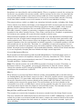
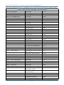
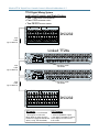
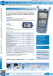
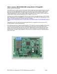
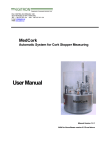
>F=4AB<0=D0;0334=3D<
E4AB8>= $D?30C4
Mackie TT24 Digital Live Console Owner’s Manual Addendum v1.5
Contents
TT24 Version 1.5 Features..................................................................3
1. Channel Naming..............................................................................3
2. Effect Tap Delay..............................................................................7
3. OPT•24T ADAT Expansion Card Implementation....................10
4. U100 Network Card Implementation..........................................11
4.1 U-NET.................................................................................11
4.2 DS3232 Digital Snake.......................................................12
4.3 Console Linking................................................................12
Don’t forget to visit our website at www.mackie.com for
more information about this and other Mackie products.
Part No. SW0476 Rev. A 05/07
©2007 LOUD Technologies Inc. All Rights Reserved.
R
Mackie TT24 Digital Live Console Owner’s Manual Addendum v1.5
TT24 Version 1.5 Features
This addendum to the TT24 Owner’s Manual highlights the new features included with the
version 1.5 software upgrade.
1. Channel Naming
Manual Section: Add 6.13.6 CHANNEL NAMES
Feature Description: Allows you to add custom naming for channels. This is accomplished
from the Touchscreen or TT Control software. The custom names appear in the channel
display on the top left when a channel is selected from either TT Control or the Touchscreen.
Channel names are stored and recalled with snapshots. This means you can change to a new
set of channel names for each snapshot. They can also be filtered to prevent recall by using
the “Other” filter parameter.
To name a channel from the Touchscreen, press the Setup button and select Channel Names.
Mackie TT24 Digital Live Console Owner’s Manual Addendum v1.5
The Channel Names screen contains a two column list of the channel default names on
the left, and any custom names on the right. You can scroll through the list (using the
Touchscreen scroll bars and up down buttons) and select the channel you wish to rename.
Pressing the Rename button will display the on-screen keyboard to rename the channel.
Enter a name of six characters or less and press OK when finished.
Mackie TT24 Digital Live Console Owner’s Manual Addendum v1.5
To access Channel Naming from the TT Control software application, click the Screen Name
drop-down box and select Setup - Naming (or use the keyboard shortcut F12).
Mackie TT24 Digital Live Console Owner’s Manual Addendum v1.5
Like the Touchscreen, a two-column list shows the channel default names on the left and any
custom names on the right. Click the RENAME button and enter the new name in the “Set
Channel Name” popup. Channel names can be up to 6 characters long. You can use the up/
down arrow keys on your keyboard to scroll to the previous/next channel for renaming. Press
Enter or click OK when finished renaming.
Click the “CLEAR CHANNEL NAME” button (or press the CLEAR button in the Touchscreen)
to clear the custom name for the selected channel.
Click the “CLEAR ALL NAMES” button (or press the CLEAR ALL button in the Touchscreen)
to reset all the channel names to their defaults.
Mackie TT24 Digital Live Console Owner’s Manual Addendum v1.5
2. Effect Tap Delay
Manual Section: Add to 6.12 Effects
Feature Description: Adds a tap delay for the delay effects. This feature can be accessed
from the Touchscreen and the TT Control software.
The tap delay is accessed on the edit page for the mono delay, stereo delay, and ping pong
effects. To access the tap delay on the Touchscreen, press the EFX button, select Mono Delay,
Stereo Delay, or Ping Pong for one of the four internal effects, and touch the Edit button.
A white TAP knob is used in the Touchscreen to set the tap delay. Simply tap the encoder
corresponding to the Tap knob to adjust the tap in beats-per-minute (BPM) to set the delay
time in milliseconds (ms). For Stereo Delay and Ping Pong, the left and right delays can be
set independently.
The delay rate is indicated by the Up/Down channel Arrow LEDs on the console. When viewing
any other screen, these are always lit, but on an EFX page they will flash to show the delay
rate. When mono delay is selected, both up and down arrows will flash together showing the
delay rate. For a stereo delay or ping pong, the left arrow button will flash showing the left
delay rate and the right arrow button will flash at the right delay rate. Pressing the buttons will
still have the same function to increment and decrement the selected channel.
In addition, the tap tempo can be set from any screen by holding CTRL and tapping the
appropriate encoder as illustrated below for each of the four effects processors. The screen
will immediately jump to the appropriate effects edit page to show the results of your change.
This allows you to adjust the delay time very quickly when a song changes.
Mackie TT24 Digital Live Console Owner’s Manual Addendum v1.5
For example, to quickly adjust the delay time of the third effect processor’s right delay line,
hold CTRL and tap the encoder corresponding to the intersection of column 3 and row R in
the figure below. The screen will immediately jump to the delay page but you can continue to
hold CTRL and tap the same encoder to edit that delay time. This trick can also be used as a
quick way to navigate to any effects screen even if it isn’t configured as a delay.
To access tap delay from the TT Control software application, click the Screen Name dropdown box and select EFX.
Mackie TT24 Digital Live Console Owner’s Manual Addendum v1.5
Select Mono Delay, Stereo Delay, or Ping Pong for one of the four internal effects and click the
EDIT button.
You can click the Tap button on-screen to adjust the tap in beats-per-minute (BPM), or click
and drag on the Delay knob to adjust the delay in milliseconds (ms). To the right of the tap
button, an LED flashes indicating the delay rate. Note that this only occurs when a TT24 is
connected.
Mackie TT24 Digital Live Console Owner’s Manual Addendum v1.5
3. OPT•24T ADAT Expansion Card Implementation
Manual Section: 4.2.1 ADAT Digital I/O
Feature Description: The OPT•24T card provides ADAT I/O for channels 13-24 when the
console is operating at the higher sample rates of 88.2 kHz and 96 kHz.
OPT.24T
F
E
OUT
INPUT A
INPUT B
INPUT C
OPT•24T INPUT D
OPT•24T INPUT E
OPT•24T INPUT F
OUTPUT A
OUTPUT B
OUTPUT C
OPT•24T OUTPUT D
OPT•24T OUTPUT E
OPT•24T OUTPUT F
D
ADAT EXPANSION CARD
F
E
IN
D
44.1/48 kHz 88.2/96 kHz
25-32
25-28
33-40
29-32
41-48
33-36
N/A
37-40
N/A
41-44
N/A
45-48
1–8
1–4
9–16
5–8
17–24
9–12
1-8
13–16
9-16
17–20
17-24
21–24
ADAT Digital I/O Channels at 44.1/48 and 88.2 /96 kHz Sample Rates.
Note: ADAT Digital Inputs are routed to the Digital Bank (25-48).
ADAT Digital Outputs are fed by the bank with Input DSP assigned in Setup > Operation.
10
Mackie TT24 Digital Live Console Owner’s Manual Addendum v1.5
4. U100 Network Card Implementation
Manual Section: Add 6.13.5 Expansion
Feature Description: The U100 network card enables the TT24 to communicate with
external devices, including a second TT24 and the DS3232 Digital Snake, using a standard
Cat5 cable.
U100
NETWORK CARD
U-NET
There are two indicating LEDs on the U100 network card. The green LED ( Q ) lights as soon
as communication is established with another device and indicates that it has successfully
joined the network. The red LED ( ! ) lights if an error is detected anywhere on the network.
Note: Make sure the TT24 has been updated with the latest firmware. After updating the
TT24, install the U100 network card and make sure the U100 card has been updated with the
latest firmware. Go to our website to get the latest firmware and software downloads:
http://www.mackie.com/products/tt24/software.html
Note: When updating a console or card, make sure the console is configured as a “Master”
(see “Console Mode” on next page) during the update procedure.
4.1 U-NET
U-NET is LOUD Technologies’ audio system networking solution. Current audio networks
have limitations that hindered implementing some of our ideas and concepts, so we developed
our own audio distribution and control network that does everything we needed it to do
and more. You will see more products from the LOUD Technologies family with the U-NET
connection, enabling them to be connected and take advantage of a unified system of audio
distribution and control.
Refer to the “Ubiquity Networking Whitepaper” for more information about this subject.
http://www.eaw.com/APP/papers.html
11
Mackie TT24 Digital Live Console Owner’s Manual Addendum v1.5
4.2 DS3232 Digital Snake
After you have installed the new version 1.5 firmware in your TT24, you can install the
U100 network card, which allows you to connect the Mackie DS3232 Digital Snake. The
DS3232 provides 32 mic/line inputs and 32 line-level returns, allowing you to connect all your
microphones and DI’s to the DS3232 on-stage, and send monitors and mains back to the stage
from the TT24, using a single Cat5 cable.
See the DS3232 Owner’s Manual for more information about connecting and using the DS3232.
http://www.mackie.com/products/DS3232/pdf/DS3232_OM.pdf
U-NET
DS3232
POWER
PUSH
1
PUSH
2
PUSH
17
PUSH
3
PUSH
18
PUSH
COMM
24-BIT / 96kHz DIGITAL SNAKE
4
PUSH
19
PUSH
5
PUSH
20
PUSH
6
PUSH
21
PUSH
22
PUSH
INPUTS
8
7
PUSH
PUSH
23
PUSH
24
PUSH
1
2
3
4
5
6
7
17
18
19
20
21
22
23
9
PUSH
25
PUSH
RETURNS
8
24
10
PUSH
11
PUSH
26
PUSH
12
PUSH
27
PUSH
13
PUSH
28
PUSH
14
PUSH
29
PUSH
15
PUSH
30
PUSH
16
PUSH
31
PUSH
32
PUSH
9
10
11
12
13
14
15
16
25
26
27
28
29
30
31
32
4.3 Console Linking
After you have installed the new version 1.5 firmware in your TT24, you can link two TT24
consoles with a U100 network card installed in each console. Simply connect the two U100
cards together using a standard Cat5 cable and designate one console as the “Master” and the
other console as the “Slave.”
When two consoles are linked in this fashion, the slave console sends its outputs (Left,
Right, Center, Aux Sends, Group/Matrix Outputs, Solo) to the master console where they are
summed with the master console’s outputs. The summed outputs are then sent to the physical
outputs on both the master and slave consoles, so the master and slave outputs are identical
and include the signals from both consoles. Output DSP (EQ and dynamics) and effects take
place on the master console.
Linking two consoles provides the benefits of twice as many available inputs, creating a
massive system with the following channel counts:
— 96 Input Channels (48 analog, 48 digital)
— 16 Line Inputs
— 4 Stereo EFX Returns
— 12 Aux Sends
— 8 Flex Groups
— 8 Matrix +
— Left/Right/Center(Mono)
Linking also provides 24 more channel strips to control inputs. Since you also have four
additional group faders, you can control all eight groups without banking. Finally, you now have
two independent touchscreens allowing control of parameters from either control surface.
12
Mackie TT24 Digital Live Console Owner’s Manual Addendum v1.5
Console Mode
To configure each console as master or slave, push the SETUP button and select OPERATION.
CONSOLE MODE allows you to select either MASTER or SLAVE for the console.
Note: One console must be designated MASTER and one console must be designated SLAVE
in order for console linking to operate properly. Once you have configured the consoles, they
will remain in that configuration until you change them using the CONSOLE MODE selection.
If you disconnect the console designated as the SLAVE, you must change it back to MASTER
in order for it to operate properly on its own.
In order for TT Control to work correctly, it must be assigned the same Master/Slave status as
the console to which it is connected. From the TT Control application, click the Screen Name
drop-down box and select Console Mode. Select the console mode that corresponds to the
TT24 your computer is connected to. Note that MASTER or SLAVE appears in the title bar.
13
Mackie TT24 Digital Live Console Owner’s Manual Addendum v1.5
Linking Parameters
Once you have configured the two consoles for linking, some of the TT24 parameters become
linked together. In fact, the console parameters fall into one of three categories:
Global — The parameter is linked and can be controlled from either console.
Local — The parameter is not linked, and can be controlled independently on each console.
Master — The parameter is only controlled on the master console, and is disabled on the
slave console.
Here is a quick rundown of the linking parameters when two consoles are linked.
Bank Select: Bank selection operates locally, and can be performed independently on either
console.
V-Pot Control: V-Pot selection operates locally, and can be performed independently on either
console.
Touchscreens, Touchscreen Knobs, and QuickMix Encoders: Touchscreens and QuickMix
Encoders operate locally, but linked parameters can be controlled from either touchscreen.
Solo PFL/AFL: Solo operates globally. Soloing a channel on either console will flash the Rude
Solo LED and pass the soloed signal to the monitor and phones outputs on both consoles.
Changing between PFL and AFL can be done from either console, as can Clear Solo.
Bank 1: Analog Inputs
The analog input strips operate locally and are not linked, including the Aux Sends, EQ,
dynamics, and Group Assignments. For example, Channel 1 on the slave console is completely
independent from Channel 1 on the master console.
Bank 2: Digital Inputs
The digital input strips operate locally and are not linked, including the Aux Sends, EQ and
dynamics (when assigned to the digital inputs or when a UFXII is installed), and Group
Assignments.
Bank 3: Line Inputs 1-8, Internal EFX Returns 1-8, Card Inputs 1-8
The analog line input strips operate locally and are not linked, including the Aux Sends, EQ,
and Group Assignments.
The Internal EFX Returns operate globally and are linked. The EFX selection and EFX editing
can be controlled from either console. The DSP processing takes place on the master console.
The Card Inputs (available when a second U100 card is installed with a DS3232 connected)
operate locally and are not linked, including the Aux Sends, EQ, dynamics, and Group Assignments.
Bank 4: Aux Sends 1-12, Groups 1-8, L/R/C
The master aux sends operate globally and are linked. The master aux sends can be
controlled from either console, including the EQ and dynamics controls. The DSP takes place
on the master console.
The groups 1-8 operate globally and are linked. The groups can be controlled from either
console, including the EQ and dynamics controls. The DSP takes place on the master console.
The left, right, and center strips operate globally and are linked. The left, right, and center
can be controlled from either console, including the EQ and dynamics controls. The DSP
takes place on the master console.
14
Mackie TT24 Digital Live Console Owner’s Manual Addendum v1.5
Snapshots
Snapshots are stored locally and recalled globally. When a snapshot is stored, the settings for
the master are stored on the master console, and the settings for the slave are stored on the
slave console. Both consoles store their settings under the same snapshot number, and the
selected snapshot number is linked so that it is always the same on both consoles. Pressing
recall from either console causes each console to recall its own individual settings.
The output settings (which are global) are stored on the both consoles, including Left, Right,
Center, Master Aux Sends, and Groups, even though the DSP is occurring on just the master
console. Snapshot channel parameter filtering and effects filtering is global, while channel
filtering is local (shared masters like aux sends, EFX returns, and outputs are global).
Title edit (rename) is global, so renaming a snapshot on one console will rename the same
snapshot on the other console. Protect, Clear, Store, and Recall are all global, so performing
the action on one console will cause the other console to do the same.
Linked console snapshots will work when the consoles are later disconnected and operating
on their own, but it might lead to unexpected results as not all of the same parameters and
routing options exist. Even stranger things can happen when recalling snapshots created on
separate consoles when the two consoles are linked, especially if a snapshot number is full on
one console but not on the other. Therefore, it’s a good idea to separate snapshots that are
saved when the console is operating on its own from snapshots saved when the consoles are
linked. You might reserve snapshots 1-49 for individual consoles, and 50-99 for linked consoles
if you are frequently changing between linked and single console operation.
Console Backup and Restore
Each console must be backed up and restored independently. Console backup creates an
offline file that contains all snapshots and presets currently stored on the TT24. Console
backup and restore are performed only from the TT Control application (Files > Backup
Console and Files > Restore Console).
Note: The console must be set to MASTER to perform a backup or restore. Therefore, to
backup or restore a slave console, you must first disconnect it from the master console,
change the console and TT Control to MASTER, perform the backup or restore, and then
reconfigure the console back to SLAVE.
Matrix
When Matrix is activated, the Matrix Masters and the corresponding delay and solo settings
are linked globally, but the Matrix sources are local. The slave console’s matrix sources default
to Analog Inputs 1-11 (post-fader with levels down) for all eight Matrix Outputs (A-H), while
the master console’s matrix sources default to the groups and L/R/C(Mono) with levels set
according to the current flex group levels. The matrix inputs on the each console can be
reassigned to any of the available input sources on that console, but only the master console
can assign matrix inputs from the outputs or internal EFX returns. This extends the total
number of matrix sources for each matrix output from 11 to 22.
Sample Rate and External Clocking
The sample rate can only be changed on the master console from the Setup>Digital screen.
The slave console will automatically lock to the master over U-NET. Additionally, if you wish
to lock the system to an external word clock source, connect the external clock to the master
console only and configure the clock source to “external” on the master console. Again, the
slave will follow.
15
Mackie TT24 Digital Live Console Owner’s Manual Addendum v1.5
Refer to the following chart for a complete list of TT24 functions affected by console linking.
TT24 Console Linking Parameters
Bank 1: Analog Inputs
All Settings
Local
Bank 2: Digital Inputs
All Settings
Local
Bank 3: Line Inputs, Card Inputs
All Settings
Local
Bank 3: Internal EFX Sends
All Settings
Global
Bank 4: Aux Sends, Groups, L/R/C
All Settings
Global
Setup — Operation
Console Mode
Local
Center Mode
Global
Input DSP
Local
Noise Suppresion
Local
Pre Fader Aux Sends
Global
PC Auto Follow
Global
Select Follows Solo
Global
Units of Measurement
Global
Faders/Screen Calibrate
Local
Exclusive Solo
Global
V-Pot Speed
Global
Sample Rate
Master
Clock Source
Master
Clock Status
Determined by Sample Rate
Digital Input
Local
Sample Rate Convert
Local
1/2 Sample Rate AES/SPDIF
Local
Setup — MIDI
All Settings
Local
Setup — Expansion
All Settings
Local
Setup — Channel Names
Input Channels (Analog, Digital,
Line, Card)
Local
EFX Returns, Output Channels
Global
Monitor Meter
Global
Monitor Source
Global
Solo
Global
Utility — Stereo Input Assign
All Settings
Local
Utility — Talkback
All Settings
Master
Utility — Metering
Group/Matrix Output Meters
Global
Utility — Test Tones
All Settings
Master
Utility — User Bank
All Settings
Local
Snapshots
Channel Filtering (Analog,
Digital, Line, Card)
Local
Channel Filtering (EFX Returns,
Output Channels)
Global
All Other Settings
Global
Source Select
Local
Matrix Master Controls
Global
Setup — General
Setup — Digital
Utility — Monitor Source
Matrix
Copy/Paste
Local
16
Mackie TT24 Digital Live Console Owner’s Manual Addendum v1.5
TT24 Digital Mixing System
with Linked Consoles and Digital Snakes
• Two TT24 DIGITAL LIVE CONSOLES
• Four U100 NETWORK CARDS
• Two DS3232 DIGITAL SNAKES
U-NET
DS3232
POWER
PUSH
1
PUSH
2
17
PUSH
Cat5
Cable
(Up to 300 feet)
3
PUSH
4
PUSH
18
5
PUSH
19
PUSH
COMM
24-BIT / 96kHz DIGITAL SNAKE
PUSH
20
PUSH
6
7
PUSH
21
PUSH
PUSH
INPUTS
8
PUSH
22
PUSH
23
PUSH
PUSH
24
2
3
4
5
6
7
17
18
19
20
21
22
23
10
PUSH
25
PUSH
1
9
PUSH
26
PUSH
RETURNS
8
24
11
PUSH
PUSH
12
13
PUSH
27
PUSH
PUSH
28
14
29
PUSH
15
PUSH
PUSH
PUSH
30
16
PUSH
31
PUSH
PUSH
32
PUSH
9
10
11
12
13
14
15
16
25
26
27
28
29
30
31
32
DS3232
Linked TT24s
MIDI
USB
24
ADAT DIGITAL I/O
C
OUT
LITE PIPES 1-24 OUT
B
A
C
LITE PIPES 1-24 IN
B
IN
23
22
21
20
19
18
17
16
15
14
13
12
11
10
9
8
7
6
5
4
3
2
1
A
AES/EBU
WORD
CLOCK
SPDIF
POWER
OUT
IN
OUT
IN
OUT
LINE
LINE
LINE
LINE
LINE
LINE
LINE
LINE
LINE
LINE
INSERT
INSERT
INSERT
INSERT
INSERT
INSERT
INSERT
INSERT
INSERT
INSERT
LINE
LINE
INSERT
INSERT
LINE
LINE
LINE
LINE
LINE
LINE
LINE
LINE
LINE
LINE
LINE
INSERT
INSERT
INSERT
INSERT
INSERT
INSERT
INSERT
INSERT
INSERT
INSERT
INSERT
INSERT
TALKBACK
LINE
CD/TAPE A
IN
EXPANSION
U100
U100
CARD A
CARD B
MAINS OUT
GROUP/MATRIX OUT
SENDS
L
AUX 12
AUX 11
AUX 10
AUX 9
AUX 8
AUX 7
8
7
6
5
CD/TAPE B
AUX 6
AUX 5
AUX 4
AUX 3
AUX 2
3
2
1
LEFT
LINE INPUTS
AUX 1
MONITOR
R
8
7
6
5
4
3
2
1
LEFT
RIGHT
IN
CTR/MONO
OUT
LEFT
RIGHT
4
RIGHT
MONO
Expansion Cards
Two U100s
Cat5
Cable
(Up to 300 feet)
MIDI
USB
24
ADAT DIGITAL I/O
C
OUT
LITE PIPES 1-24 OUT
B
A
C
LITE PIPES 1-24 IN
B
IN
23
22
21
20
19
18
17
16
15
14
13
12
11
10
9
8
7
6
5
4
3
2
1
A
AES/EBU
WORD
CLOCK
SPDIF
POWER
OUT
IN
OUT
IN
OUT
LINE
LINE
LINE
LINE
LINE
LINE
LINE
LINE
LINE
LINE
INSERT
INSERT
INSERT
INSERT
INSERT
INSERT
INSERT
INSERT
INSERT
INSERT
LINE
LINE
INSERT
INSERT
LINE
LINE
LINE
LINE
LINE
LINE
LINE
LINE
LINE
LINE
LINE
INSERT
INSERT
INSERT
INSERT
INSERT
INSERT
INSERT
INSERT
INSERT
INSERT
INSERT
INSERT
TALKBACK
LINE
CD/TAPE A
IN
EXPANSION
U100
U100
CARD A
CARD B
MAINS OUT
GROUP/MATRIX OUT
SENDS
L
AUX 12
AUX 11
AUX 10
AUX 9
AUX 8
AUX 7
8
7
6
5
CD/TAPE B
7
6
5
4
3
2
1
LEFT
RIGHT
CTR/MONO
IN
Cat5
Cable
(Up to 300 feet)
RIGHT
Expansion Cards
Two U100s
U-NET
POWER
2
PUSH
17
PUSH
3
PUSH
18
PUSH
COMM
24-BIT / 96kHz DIGITAL SNAKE
PUSH
1
PUSH
4
PUSH
19
PUSH
5
PUSH
20
PUSH
6
PUSH
21
PUSH
22
PUSH
INPUTS
8
7
PUSH
PUSH
23
PUSH
1
2
3
4
5
6
7
17
18
19
20
21
22
23
9
PUSH
24
PUSH
10
PUSH
25
PUSH
RETURNS
8
24
AUX 5
AUX 4
AUX 3
AUX 2
3
2
1
LEFT
AUX 1
MONITOR
OUT
LEFT
DS3232
AUX 6
LINE INPUTS
R
8
11
PUSH
26
PUSH
12
PUSH
27
PUSH
13
PUSH
28
PUSH
14
PUSH
29
PUSH
15
PUSH
30
PUSH
16
PUSH
31
PUSH
32
PUSH
9
10
11
12
13
14
15
16
25
26
27
28
29
30
31
32
80 Inputs
• 32 mic inputs on each DS3232
• 8 line inputs on each TT24
Note: All 32 mic inputs from the
DS3232 are equipped with full DSP
(Gates, Comp, and 4-band EQ)
17
DS3232
23 Outputs
• 12 Aux outputs
• 8 Flex Group/Matrix outputs
• Left, Right, Center/Mono outputs
Note: Outputs are mirrored on
both snakes
4
RIGHT
MONO
Mackie TT24 Digital Live Console Owner’s Manual Addendum v1.5
18
Mackie TT24 Digital Live Console Owner’s Manual Addendum v1.5
19
16220 Wood-Red Road NE • Woodinville, WA 98072 • USA
www.mackie.com • [email protected]
United States and Canada: 800.898.3211�
Fax: 425.487.4337�
Europe, Asia, Central and South America: 425.487.4333
Middle East and Africa: 31.20.654.4000