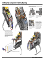
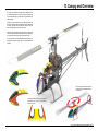
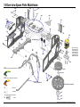
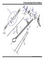
1
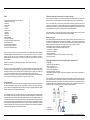
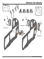
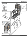
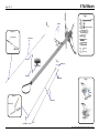
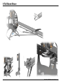
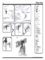
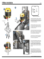
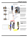
Manual
Mikado Model Helicopters GmbH • Friedrich-Klausing-Straße 2 • 14469 Potsdam • Germany
phone +49 (0)331 23749-0 • fax +49 (0)331 23749-11 • www.mikado-heli.de
© Mikado Model Helicopters GmbH 2013, V1.0019
Index
Safety Instructions/ Tools for Assembly & RC Equipment 1 Mainframe + Servo Mounting
2 Mainframe 3 Landing Struts
4 Tail Rotor
5 Tail Boom 6 Tail Boom Brace
7 Main Gear
8 Swashplate
9 Rotor Head
10 Motor Installation
11 Wiring RC Components
12 Wiring RC Components + Battery Mounting
13 Canopy and Overview
14 Overview Spare Parts Mainframe
15 Overview Spare Parts Tail Boom
16 Overview Spare Parts Rotor Head
Additional precautions for the prevention of injuries or damage:
2
3
4
5
6
7
8
9
10
11
12
13
14
15
16
17
18
Thank you very much for your purchase of the Mikado LOGO 480. Prior to installation, please read and understand
this manual completely and follow all instructions exactly. If any instructions are not clear to you or if you have any
questions, you must contact us. You can reach Mikado on the LOGO-Forum on www.vstabi.info or contact the
Mikado support hotline via email or phone. Do not under any circumstances fly this helicopter if you are unsure of
setup or assembly.
Experience in handling and flying aRC Helicopter are required in order to operate a LOGO 480.
Minimum Age : 14 Years
The LOGO 480 comes partially pre-assembled, i.e. the structural components are already screwed together.
However, the screws are not yet secured with Loctite. Throughout the manual you will not always be asked to secure
each screw. Nevertheless, you must secure all screws in all components yourself. In addition, it is necessary that
you secure all other screwed connection, by which you will assemble the different components of the
LOGO 480. We recommended to use securing glue Loctite 243 (blue). Please follow the recommendations of the
Loctite manufacture and allow proper curing time for the Loctite prior to flying the model.
Safety Instructions:
RC Helicopters are not toys and must be treated with due diligence. Unless you use this helicopter responsibly it
can cause of severe injury and immense damage. Inappropriate use of this product can result in injury or death.
Each user must have the appropriate knowledge and skill to operate any RC Helicopter. Manufacturer / reseller
assumes no liability for the use or operation of this helicopter.
Before you power on the helicopter, you must ensure that all screws and associated hardware are secured. One
single lose screw can cause the helicopter to become uncontrollable resulting in a crash or injury to personnel.
Also it is very important that you must check the model frequently and exchange any parts that show signs of
deterioration or wear.wearing out. Failure to complete frequent pre and post flight inspections will result in flying an
unsafe model and increasing the risk of damaging the helicopter and possibly injuring yourself and/or others. Use
only original Mikado parts and electronic components which are recommended by Mikado.
Always keep a minimum of 10 yards away from a spinning rotor head. Components that run hot such as the ESC
and Motor should never be touched until ample cool down time has been provided.
Before powering on:
Never operate the helicopter inside closed rooms as this helicopter is intended for operation outside and may only
be operated in sites where operation of Radio Control models is permitted. . Keep the helicopter at safe distance to
any persons or live animals at all times. When trimming, keep a minimum distance of 10 yards for safety and never
operate the helicopter alone. Always take someone with you, who can help in emergency situations.
The helicopter must also not be operated in the following circumstances:
• when children are present or in places where people are gathering
• close to houses or in park areas
• inside any rooms or buildings
• places with limited space
• in adverse weather conditions, such as rain, snow, hail or during strong winds
• Near trees or power lines
Techical specifications which must be obeyed during the operation of the
LOGO 480:
• maximum rotor head rpm: 2500 U/min.
• maximum pitch travel: +/- 12°
• Length of rotor blades: 473mm
• Lipo battery: 6S 3300-4000mAh
• admissible temperature 0° - 35° Celsius
If these values are exceeded, the electronic components may experience overload. This may result in damage or a
crash of the helicopter.
Before the first flight, you must check proper functioning of the motor, the ESC and the VBar. To do this, please refer
to the respective manuals. For safety reasons, these tests should be performed without mounting the main rotor
blades and the tail rotor blades. It is advisable to fly moderately during the first flights. This is because you need to
get used to the new size of this helicopter during the first few flights. Do not underestimate the size and power of
this helicopter. Keep a safe distance from the ground to provide for ample reaction time.
thread lock
5
Minute
Epoxy
You are responsible for any injury and damage that may be caused by this helicopter. It is recommended that your
radio components be tested prior to installing in this helicopter. Improper radio installation or inadequate battery
voltage can result in the loss of control of the helicopter. Proper knowledge of your radio equipment is required prior
to flying this helicopter. You must check if other persons are using an RC-controlled model or device simultaneously,
as this may result in interference. If the helicopter behaves in an unusual or strange way, you must land it immediately
and turn off the power. Please meticulously check all of your radio gear and find/fix the problem before you continue
to operate the helicopter This is to avoid any accidents. As one irregularity can cause other defects or problems, an
increased risk of failure will ensue, if the first problem is not fixed.
ball
link
pliers
5
Minute
Epoxy
needle
nose
pliers
grease
pitch gauge
scissors
hex wrenches
1,5/2,0/2,5/3,0/4,0 mm
Manual LOGO 480 - ©Mikado Model Helicopters GmbH -2013- Page 2
1 Mainframe + Servo Mounting
Bag 1+ 3
M2x10
Bag 1
4x
8x
M2x10
M2
16mm
16mm
16mm
14-16mm
12x
4x
4x
M2,5x8
Bag 3
M2,5x8
M2,5x12
M2,5 Stopp
M2,5x8
M2x10
M2,5x8
M2,5x8
M2,5x8
Please secure the servo screws
with thread lock (Loctite).
Please secure the servo screws
with thread lock (Loctite).
M2,5x8
M2,5x8
Please secure the servo screws
with thread lock (Loctite).
Manual LOGO 480 - ©Mikado Model Helicopters GmbH -2013- Page 3
2 Mainframe
Bag 1
4x
6x
14x
3x17
3x7x3
Secure all srews with thread lock!
M2,5x8
M3x14
Bag 1
M3x8
M3x8
M3
M2,5x6
4x
M2,5x8
2x
M3x18
2x
M3x5x7
18x
M2,5
2x
M3
2x
3x17
4x
3x5x2,5
4x
3x7x3
2x
M3x14
2x
M3 Stopp
M2,5x6
M3 Stopp
M3x16
M2,5x6
M3 Stopp
M3x14
M2,5x8
M2,5x6
M3x8
M3x16
Manual LOGO 480 - ©Mikado Model Helicopters GmbH -2013- Page 4
3 Landing Struts
Bag 1+5
Bag 1
4x
Bag 5
10x19x5
4x
SW5x19
4x
M3x20
10x19x5
4x
M3x16
4x
M3
4x
M3x3
M3 Stopp
M3x20
M3x16
M3x16
M3x3
M3x20
Secure all srews with thread lock!
Manual LOGO 480 - ©Mikado Model Helicopters GmbH -2013- Page 5
4 Tail Rotor
Bag 5+7
Large
inner diameter
1
5x8x0,5
4x8x3
Do not apply thread
lock here
M3x16
Small
inner diameter
M2,5x6
Apply grease
on bearing
4x8x2
2,5x6x0,5
a
M3 Stopp
Apply thread lock only in the
theaded section inside the
tail rotor hub!
b
c
d
Bag 7
3x10x4
M3x8
5x13x4
M2,5x6
5x8x0,5
2x
2,5x5x0,5
2x
3x5x9
M3x35 (5x)
2x
1
M2,5x6
2x
4x8x3
2x
4x8x2
M3x16
2x
2x
4x8x3,5
2x
M3
1x
M3x3
2
Bag 7
5x
3x5
1x
M3
M2,5x6
5x22,3
1x
Bag 5
2
22,3mm
M3x14
M2x10
3x5x5
3x6x2,5
1x
1x
3x5x5
M2x10
1x
Kugel/ball/Rotule
1x
3x5x0,5
1x
3x5x0,5
2x
2
22,3mm
M3 Stop
(5x)
2x
M3x5
5x
M3x30
2x
3x5x9
1x
3x10x4
2x
3
5x13x4
M3x14
3x6x2,5
Manual LOGO 480 - ©Mikado Model Helicopters GmbH -2013- Page 6
5 Tail Boom
Bag 7+8+11
Bag 8
2x
M3x30
2x
M3
4x
Kugel/ball/Rotule Ø6x3
4x
Bag 8 + 11
5 Min. Epoxy
M3x30
2x
Ø4x480 mm
2x
M3x16
2x
M3x16 (2x)
1x
M2x6
1x
M2 Stopp
M2x6
Ball Ø6 mm
M2 Stopp
M3 Stopp
Bag 7
M3x3
Bag 8 + 11
Ø5x450 mm
5Min. Epoxy
Kugel Ø6 mm
Manual LOGO 480 - ©Mikado Model Helicopters GmbH -2013- Page 7
6 Tail Boom Brace
M3x14
M3x14
Manual LOGO 480 - ©Mikado Model Helicopters GmbH -2013- Page 8
7 Main Gear
Bag 4
After installing the belt pulley, check the direction
of the tail rotor. Turn the main rotor clockwise.
The tail must also turn clockwise.
Bag 4
1x
10x16x0,5
4x
M3x8
1x
10x16x0,2
1x
1x
10x16x0,5
3x16
1x
M2,5x8
Please apply grease to the
one way bearing.
10x16x0,2
After mounting the main gear, it will have 1 mm
axial play.
Manual LOGO 480 - ©Mikado Model Helicopters GmbH -2013- Page 9
8 Swashplate
Bag 9
Bag 9
3x
M2,5x27
3x
M3x61
6x
13mm
Secure all bolts with thead lock!
A hint for mounting the ball links:
One surface of the ball link is easier to clip
on. If link is too hard to clip on, turn it by 180
degrees.
Manual LOGO 480 - ©Mikado Model Helicopters GmbH -2013- Page 10
9 Rotor Head
Bag 10
1
M3x6
M4x12
Apply grease to bearing. Mounting
direction is not critical.
4x12x1
Small
inner
diameter (6,0mm)
10,5x14x1
8x11x1
8x14x4
Note: The
washer with the
larger inner diameter has
play on the spindle shaft. The
washer with the smaller inner diameter fits tightly.
Prior to assembly, please supply
silicon oil or grease on o-rings and
spindle shaft.
M3x6
2x
6x
7x3 O-Ring
4x
8x11x1
2x
8x11x0,5
Center the spindle
shaft exactly!
10,5x14x1
7x4,5
After mounting, the blade holders
will move a little bit tightly at first.
M4x12
5
4
3
1x
Large
inner
diameter (6,2mm)
8x11x1 (hard dampening)
8x11x0,5 (soft dampening
Bag 10
2
3x12
3x7x3
6
8x14x4
4x
2x
4x
6x14x5
10,5x14x1
M3x16
1x
M3x16
16 mm
M3x22
7
3x5x0,5
M3x20
8
2x
3x6x2,5
3x5x2
M3x22
2x
2x
M4x12
M3x25
2x
2x
4x12x1
2x
M3 Stop
2x
2x
Ø4,8x3
3x12
4x
3x7x3
4x
3x6x2,5
2x
3x5x2
2x
2x
M3x20
M2,5x27
4x
2x
3x5x0,5
Manual LOGO 480 - ©Mikado Model Helicopters GmbH -2013- Page 11
10 Motor Installation
Bag 6
Bag 6
6x
M3x10
1x
M3x3
4x
M2,5x10
Installation of Motor and Gear Mesh
1) Mount the motor as shown in image (1), using the four
countersunk screws M3x10. Make sure that the M3x3 set
screw is placed at the flattened area of the motor shaft. Do
not fasten the set screw now (it can only be used once!)
- the pinion will be positioned later.
M2,5x10
Do not tighten yet!
M2,5x10
2) Mount the motor plate, as shown in (2), using the four
set screws M2.5x10 and the additional aluminum braces.
Do not tighten the screws completely, as the entire motor
plate should be still moveable.
3) Push the motor with pinion as close to the main gear as
possible, see image (3). The centers of the herringbone of
pinion and main gear must be aligned exactly. The main
gear has a slight axial play for easy adjustment.
M3x10
4) Now fix the pinion to its final position by tightening the
M3x3 set screw. This set screw can only be used once.
You must secure it by using thread lock!
5) Pinion and main gear should have minimal gear mesh.
The main gear is not 100 % round (due to the free wheel
unit). Therefore there will be a small area without any
gear mesh. This is normal. Do not use paper for setting
the gear mesh (this does not work with the herringbone
gear!). Now secure the M2.5 socket head cap screw with
thread lock.
6) During pre-flight check, before each flight, the gear
backlash must be checked! Also, the gear must be checked for wear and tear. If necessary, adjust the gear mesh
and/or replace the gears. Note that the motor ball bearing
can also be subject to wear and tear, as well as to excess
play.
Manual LOGO 480 - ©Mikado Model Helicopters GmbH -2013- Page 12
11 Wiring RC Components
Do not connect the orange wire - unless
you are using PRO-Version of the (Mini-)
VBar.
Installation and Operation of the YGE controller
in LOGO 480
This YGE 90 LV controller is a special edition for Mikado
Model Helicopters. The controller has a Power-BEC and
its software is pre-programmed for LOGO helicopters. The
current version contains the internal governor (constant
head speed) and has a pre-programmed BEC voltage of
5.7 V. This YGE 90LV controller can be used with 6S lipo
batteries in the LOGO 480 without any adjustments. In its
current state, this controller can only be used in LOGO
helicopters operated by Lipo batteries of size 6S or less.
additional power supply
connect to RX B (three wires)
1) Position the controller on the carbon plate in front
of the motor. In this way you can measure the correct
length of the three cables connecting the motor. Then
shorten the cables as necessary. Solder the three
4 mm gold connectors and secure the connectors
with shrinking tube against short-circuiting.
2) Now attach the controller in its final position on the carbon
plate, using velcro and cable straps. Make sure that the
printed sticker faces upwards, as it contains the heat sink.
3) Connect the master wire of the YGE controller to the RX
B socket on the Mini-VBar. The slave wire (+/-) serves as
an additional power supply. It can be placed into any free
channel, but not RX A. The single signal wire is used only in
connection with the VBar governor (PRO-Version necessary).
Instructions for this can be found on www.vstabi.info.
4) Before powering up the motor and controller for the first
time, you must remove the main and tail rotor blades!
5) Please read the additional information and safety warnings
included to the controller by YGE. This controller can be
re-programmed using a YGE programming card. After
re-programming it can be used in other applications.
Manual LOGO 480 - ©Mikado Model Helicopters GmbH -2013- Page 13
12 Wiring RC Components + Battery Mounting
We recommend the use of the anti-static kit (item no. 4358 included here). This reduces
potential effects of static discharge of the belt.
Step 1: Connect one eye of the short
wire to the tail boom and the other to
the tail drive pulley.
Step 3: Attach the second short wire
to the motor plate and connect it to the
wire on the tail boom.
Step 2: Attach the eye of the long wire
to the upper or the lower surface of
the tail boom.
Make sure that no cables can rub
against any sharp edges. For protecting the cables use edge protector
item no. 4594 and braided sleeving
wrap, item no. 4593. Prior to each
flight, check all cables to make sure
they are whole and not damaged.
Prior to each flight, check that all
connectors firmly connected.
During flight, all cables and connections are
subject to vibration and acceleration forces.
This is why it is necessary to place all wires and
cables carefully. All connectors must be firmly
connected. Use only connectors with protection
against reversing. If wires are too short, they
can get disconnected during flight. This must be
absolutely avoided.
For securing the battery on the tray, use Velcro.
Manual LOGO 480 - ©Mikado Model Helicopters GmbH -2013- Page 14
13 Canopy and Overview
The canopy of the LOGO 480 is mounted via four attachment points.
The two attachment points in the front ensure that the canopy sits well
on the chassis during flight. In the back, the canopy is attached by two
rubber grommets.
Important note: A special feature of the Logo 480 canopy ist that it the
back part is fully closed. Take your time when mounting and dismounting
the canopy. Use proper care when sliding the canopy over the rotor
shaft, to avoid damage on the surface of the canopy.
Before each flight, check that the canopy sits securely. If the canopy sits
too lose, this can deteriorate the flight performance of the helicopter. If
the canopy becomes lose during flight, the helicopter will crash.
This canopy is 100% hand-made. Small irregularities in the surface, the
airbrush design or color are normal. They do not constitute a reason for
complaint.
Prior to the first flight, check the direction of
the main rotor and the tail rotor. Both must
turn clockwise.
For extra protection of the canopy, you may mount
edge protector, item no. 4594. You may need to
enlarge the cut-outs.
Manual LOGO 480 - ©Mikado Model Helicopters GmbH -2013- Page 15
14 Overview Spare Parts Mainframe
4815
4824
4814
4817
1329
4816
2364
4812
4278
4821
4814
4813
4465
4818
4810
4824
930 (ball bearing)
4089
4817 (17 teeth, M0,5)
4118 (18 teeth, M0,5)
4119 (19 teeth, M0,5)
4120 (20 teeth, M0,5)
4121 (21 teeth, M0,5)
4122 (22 teeth, M0,5)
4123 (23 teeth, M0,5)
4823
4814
4820
4811
04836 Canopy LOGO 480 blue/yellow/neon green
4059
2010
04835 Canopy LOGO 480 neon yellow/red
4824
4822 Logo 480 (black)
10x
M2,5 #4552
10x
M3 #4553
3x
10x
M2,5x27 #4834
#1565
4060 (212 teeth, M0,5)
4067
2009
1344
Manual LOGO 480 - ©Mikado Model Helicopters GmbH -2013- Page 16
15 Overview Spare Parts Tail Boom
4235
1962
4274
4831
4069
3077
3069
3051
2447
2466
4832
2476
2397
2462
4827
4232
3049
727
4827
4825
4356 EDGE 72
4425 EDGE 86
4830
4828
2444
4826 (Set)
Manual LOGO 480 - ©Mikado Model Helicopters GmbH -2013- Page 17
16 Overview Spare Parts Rotor Head
1975
1972
4205
2349
4051
2350
1574
4049
4833
2351
2347
951
952
930
4133
1916
2330
4834 (27mm)
1565
www.mikado-heli.de
Concieved and Constructed by Mehran Mahinpour Tirooni, Rendering: André Doil • Layout & Realisation: André Doil
Manual LOGO 480 - ©Mikado Model Helicopters GmbH -2013- Page 18