1
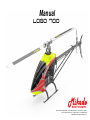
Manual
LOGO 700
Mikado Model Helicopters GmbH • Friedrich-Klausing-Straße 2 • 14469 Potsdam • Germany
phone +49 (0)331 23749-0 • fax +49 (0)331 23749-11 • www.mikado-heli.de
© Mikado Model Helicopters GmbH 2012, V1.0
Index
Safety Instructions/ Tools for Assembly & RC Equipment 1 Mainframe
2 Servo Mounting
3 Main Gear
4 Landing Struts and Canopy Holder
5 Motor Installation
6 Tail Rotor
7 Torque Tube
8 Tail Boom Mounting
9 Tail Boom Brace
10 Swashplate
11 Rotor Head
12 Wiring RC Components
13 Mounting ESC and Voltage Regulator 14 Battery Mounting
15 Main Rotor Blades and Tail Rotor Blades
16 Canopy and Overview
17 Overview Spare Parts Mainframe
18 Overview Spare Parts Gear Box
19 Overview Spare Parts Tail Boom
20 Overview Spare Parts Tail Rotor
21 Overview Spare Parts Rotor Head
Additional precautions for the prevention of injuries or damage:
2
3
4
5
6
7
8
9
10
11
12
13
15
16
17
18
19
20
22
23
24
25
Thank you very much for your purchase of the Mikado LOGO 700 XXtreme. Prior to installation, please read and
understand this manual completely and follow all instructions exactly. If any instructions are not clear to you or if you
have any questions, you must contact us. You can reach Mikado on the LOGO-Forum on www.vstabi.info or contact
the Mikado support hotline via email or phone. Do not under any circumstances fly this helicopter if you are unsure
of setup or assembly.
This helicopter is not suitable for beginners. It is expected that you have some experience in assembling and
operating an RC helicopter (model size LOGO 400 to LOGO 600, for example). You are required to adhere to the
safety instructions of this manual.
The LOGO 700 XXtreme comes partially pre-assembled, i.e. the structural components are already screwed together.
However, the screws are not yet secured with Loctite. Throughout the manual you will not always be asked to secure
each screw. Nevertheless, you must secure all screws in all components yourself. In addition, it is necessary that
you secure all other screwed connection, by which you will assemble the different components of the LOGO 700
XXtreme. We recommended to use securing glue Loctite 243 (blue). Please follow the recommendations of the
Loctite manufacture and allow proper curing time for the Loctite prior to flying the model.
Before you power on the helicopter, you must ensure that all screws and associated hardware are secured. One
single lose screw can cause the helicopter to become uncontrollable resulting in a crash or injury to personnel.
Also it is very important that you must check the model frequently and exchange any parts that show signs of
deterioration or wear.wearing out. Failure to complete frequent pre and post flight inspections will result in flying an
unsafe model and increasing the risk of damaging the helicopter and possibly injuring yourself and/or others. Use
only original Mikado parts and electronic components which are recommended by Mikado.
Always keep a minimum of 10 yards away from a spinning rotor head. Components that run hot such as the ESC
and Motor should never be touched until ample cool down time has been provided.
Before powering on the helicopter:
Never operate the helicopter inside closed rooms as this helicopter is intended for operation outside and may only
be operated in sites where operation of Radio Control models is permitted. . Keep the helicopter at safe distance to
any persons or live animals at all times. When trimming, keep a minimum distance of 10 yards for safety and never
operate the helicopter alone. Always take someone with you, who can help in emergency situations.
The helicopter must also not be operated in the following circumstances:
• when children are present or in places where people are gathering
• close to houses or in park areas
• inside any rooms or buildings
• places with limited space
• in adverse weather conditions, such as rain, snow, hail or during strong winds
• Near trees or High Tension wires
Techical specifications which must be obeyed during the operation of the
LOGO 700 XXtreme:
• maximum rotor head rpm: 2100 U/min.
• maximum pitch travel: +/- 12°
• Length of rotor blades: 700 to 750mm
• Lipo battery: 2x 6S 5000 mAh
• admissible temperature 0° - 35° Celsius
If these values are exceeded, the electronic components may experience overload. This may result in damage or a
crash of the helicopter.
Before the first flight, you must check proper functioning of the motor, the ESC and the VBar. To do this, please refer
to the respective manuals. For safety reasons, these tests should be performed without mounting the main rotor
blades and the tail rotor blades. It is advisable to fly moderately during the first flights. This is because you need to
get used to the new size of this helicopter during the first few flights. Do not underestimate the size and power of
this helicopter. Keep a safe distance from the ground to provide for ample reaction time.
Safety Instructions:
RC Helicopters are not toys and must be treated with due diligence. Unless you use this helicopter responsibly it
can cause of severe injury and immense damage. Inappropriate use of this product can result in injury or death.
Each user must have the appropriate knowledge and skill to operate any RC Helicopter. Manufacturer / reseller
assumes no liability for the use or operation of this helicopter.
You are responsible for any injury and damage that may be caused by this helicopter. It is recommended that your
radio components be tested prior to installing in this helicopter. Improper radio installation or inadequate battery
voltage can result in the loss of control of the helicopter. Proper knowledge of your radio equipment is required prior
to flying this helicopter. You must check if other persons are using an RC-controlled model or device simultaneously,
as this may result in interference. If the helicopter behaves in an unusual or strange way, you must land it immediately
and turn off the power. Please meticulously check all of your radio gear and find/fix the problem before you continue
to operate the helicopter This is to avoid any accidents. As one irregularity can cause other defects or problems, an
increased risk of failure will ensue, if the first problem is not fixed.
needle
nose
pliers
Hex Wrenches
1,5/2,0/2,5/3,0/4,0/6,0 mm
Manual LOGO 700 XXTREME - ©Mikado Model Helicopters GmbH - Page 2
Please check if the RC-plate is fitted tightly between the
frames, so that it cannot move.
If the RC-plate is loose, please apply glue (speed glue or hot
glue) to fix. A moving RC-plate can lead to vibrations and
malfunction of the gyro sensor!
Bag 1 + 2
M3x5
M2,5x12
The mainframe of the LOGO 700 XXtreme is pre-assembled.
You will find it in Box 1. Note that the screws are not secured.
You must use Loctite to secure all screws in the mainframe.
Please note, when assembling the gear box: First tighten the
set screw M3x5. While doing so, press the upper and lower frames
together. Then secure the two hex screws M2.5x12. Finally check
the gear mesh before installing the gear box into the chassis.
The belt pulley must not have axial play.
The side frames are protected by edge guard in the area of the
batteries. This prevents the batteries from getting damaged on the
sharp edges of the carbon fiber sideframes. It is very important to
keep the batteries from being damaged or even short-circuiting
in the case of a crash. The protective strip along the edges of the
sideframes is not yet glued on. You need to apply superglue to
secure it.
The gearbox of the LOGO 700 XXtreme
is pre-assembled. You will find it in Bag 2.
You must use Loctite to secure all screws
in the gearbox.
M3x8 (4x)
Manual LOGO 700 XXTREME - ©Mikado Model Helicopters GmbH - Page 3
2 Servo Mounting
A
B
M2,5x8
Bag 3
4x
M2,5
3x
M3
1x
M2
4x
M2,5x10
M2,5x8
12x
M2,5x6
M2,5x8
8x
M2,5x10
4x
3x
M2,5x10
M2,5x8
1x
20x
M2,5x12
M3x12
M2x10
M2,5
3x
16mm
16mm
16mm
16mm
C
D
M2,5x8
1x
M2x10
In the kit you will find servo mounting sets for Futaba/JR HV (11mm)
servos and Savöx HV (10mm) servos
Two different sets of servo arms are included in the kit, one for JR
servos, and one for Futaba/Savöx servos.
M2,5x6
M2,5x12
Manual LOGO 700 XXTREME - ©Mikado Model Helicopters GmbH - Page 4
3 Main Gear
0,5mm
Bag 4
6x
0,5mm
1mm
Before mounting the main rotor shaft and
the main gear, you need to remove the
third bearing block. In addition you need to
push the motor plate all the way to the back.
werden.
M3x12
2x
M3x12
1x
4x20
3x
14x20x1
2x
14x20x0,5
Please apply grease to the one-way
bearing!
1mm
0,5mm
After mounting the main gear, it will show
slight axial play. This is intended and will
make installation of the pinion easier. It will
also facilitate the correct setting of the gear
mesh.
For mounting the 4 mm pin, it is useful to use
a pair of needle nose pliers.
Manual LOGO 700 XXTREME - ©Mikado Model Helicopters GmbH - Page 5
4 Landing Struts and Canopy Holder
M3x10
Bag 5
4x
Ø5x44mm
Bag 5 contains two
additional 1 mm washers.
If necessary, you may
adjust the distance of the
canopy bolts with these.
M3x16
Ø5x42mm
M3x5
M4x10
4x
M3x16
2x
M3x10
4x
M3x5
2x
3x5x1,2
2x
M3x6
M4x10
M4x10
Glue the four caps
to the ends of the
landing skids.
Manual LOGO 700 XXTREME - ©Mikado Model Helicopters GmbH - Page 6
5 Motor Installation
Unscrew the motor plate and take it out
of the chassis. Additionally you need the
losen the screws of the counter-bearing.
Bag 6
4x
1x
4x
Solder the 5.5 mm gold connectors to the motor. Make
sure to use a soldering iron large enough to create an
adequate connection. A poor connection can lead to
irregular behavior of the motor or the ESC. High-current
plugs like these need to be perfectly isolated at all times
when connected. Otherwise there is a high risk of shorting.
M4x10
M4x5
4x9x1
11mm
The connection between the motor
pinion and the main gear needs to
show a slight gear mesh.
Manual LOGO 700 XXTREME - ©Mikado Model Helicopters GmbH - Page 7
6 Tail Rotor
M2,5x6
Bag 7
M3x16
M2,5x12
M3x16
M3x12
M2,5x6
M2,5 Stop
3x6x2,5
M2x10
Mount the distance ring so that its surface
with the shoulder shows in the direction of
the ball bearing.
2x
M2x10
1x
M2,5x16
2x
M3x20
2x
M3
1x
M2,5
2x
3x7x0,5
2x
5x10x4
4x
5x10x4
6x
4,5x2
2x
7x10x0,5
2x
5x7,8x0,6
M2x12
5x10x4
M3x24
2x
M3 Stop
6x9x0,2
3x5,5x0,2
1x
5x10x4
M3x20
Please check the gear back lash after every flight. If
gear back lash has increased, please add washers.
M3x8
M2,5x6
M2,5x16
5x10x0,2
2x
7x10x0,5
Note that the disk with the smaller inner diameter needs to be
installed on the outsinde. The disk with the larger inner diameter is
installed on the inside. You can distinguish the two disks by sliding
them (temporarily) onto the 5 mm tail shaft. Only the disk with the
smaller inner diameter will sit tightly.
Larger inner Ø
please apply grease here
Smaller inner Ø
3x7x0,5
M3x8
M3x24
1x
M2x12
1x
3x5x12,2
1x
M2
2x
3x6x2,5
1x
3x5x0,5
1x
Manual LOGO 700 XXTREME - ©Mikado Model Helicopters GmbH - Page 8
7 Torque Tube
Torque Tube assembly
Bag 8 + 12
You need to mount the torque tube. To do so, please position the four torque tube holders on the aluminium boom. Then glue them on. Using adhesive tape in
addition will prevent the holders from moving, should they become lose.
2x
60mm
260mm
160mm
220mm
M3x16
2x
M3
2x
3mm
2x
M3x16
100mm
Please use
tape here
5 min Epoxy
5 min Epoxy
5 min Epoxy
5 min Epoxy
5 min Epoxy
5 min Epoxy
Before pushing in the torque tube, please ensure
that the inside of the boom is clean. If necessary,
clean it out with a piece of cloth.
Important: Before pushing in the mounted torque
tube, generously apply grease to all four O-rings
and to the inner surface of the tail boom.
Carbon tail rotor push rod
Please apply grease to the
O-rings
Manual LOGO 700 XXTREME - ©Mikado Model Helicopters GmbH - Page 9
8 Tail Boom Mounting
M2,5x12
Loctite
M3x16
M2,5x12
M3x12
M2,5x12
Loctite
M2,5x6
M2,5x6
M2,5x12
M3x12
Manual LOGO 700 XXTREME - ©Mikado Model Helicopters GmbH - Page 10
9 Tail Boom Brace
M2 Stop
Bag 8
M2x5
M2x6
M3x12
M2,5x10
3x5x2
M3x12
Loctite
Please glue the ball links of the
tail boom support with 5-min
epoxy.
Note when mounting the ball links: If you
find it hard to clip the ball link on, turn it
180°. One side of the ball link will clip on
easily. The other one is too tight to clip on
easily.
2x
M3x12
4x
M2x12
4x
6mm
2x
3x5x2
1x
1x
2x
Loctite
M3x16
2x
2x
M2x5
M2
M3x16
M2,5x10
M2x6
Manual LOGO 700 XXTREME - ©Mikado Model Helicopters GmbH - Page 11
10 Swashplate
Loctite
Bag 9
4x7x0,8
5x
3x
33mm
M2,5x6
4x7x0,8
6x
4x7x0,8
5x
4x7x0,8
M2,5
Note when mounting the ball links: If you
find it hard to clip the ball link on, turn it
180°. One side of the ball link will clip on
easily. The other one is too tight to clip on
easily.
M2,5x6
M2,5x6
Manual LOGO 700 XXTREME - ©Mikado Model Helicopters GmbH - Page 12
11 Rotor Head 11 Rotor Head
11 Rotor Head
Bag 10
2x
M3x16
4x
M3x14
2x
Loctite
M5x34
M3x16
2x
2x
M5
3x5x0,5
2x
M5x34
M6x10
2x
6,2x12x1
M3x14
Loctite
Loctite
Please apply grease to the O-rings
and to the inner surface of the yoke.
Larger inner Ø
Please apply grease here
Smaller inner Ø
M6x10
Manual LOGO 700 XXTREME - ©Mikado Model Helicopters GmbH - Page 13
11 Rotor Head
Bag 10
4x
M3x16
1x
M4x25
2x
4x
M4 Stop
4x
M3x16
Loctite
30mm
M3x16 (2x)
Loctite
Loctite
Note when mounting the ball links: If you
find it hard to clip the ball link on, turn it
180°. One side of the ball link will clip on
easily. The other one is too tight to clip on
easily.
Manual LOGO 700 XXTREME - ©Mikado Model Helicopters GmbH - Page 14
12 Wiring RC Components
BEC oder
Lipo-Empfängerakku
2S
(1300-1500 mAh)
You are required to
use the adapter wire
for the connection
between the YGEESC and the VBar
unit.
orange
YGE ESC:
The YGE 160 provided in this combo is a special version
ESC which is already programmed. It will function exclusively
in combination with the governor function of VBar. For
programming the governor function, please follow the steps in
the VBar software shown in the two screen shots below. Should
you intend to use the YGE 160 with any other application,
it is necessary that it is re-programmed. Information on reprogramming can be obtained from YGE (www.YGE.de). More
information on the VBar Governor function can be obtained on
www.vstabi.info.
VBar:
The VBar provided here contains the 5.3 PRO Software.
For programming the VBar for LOGO 700 XXtreme, please
use the setup wizard.
BEC/receiver battery:
We highly recommend using a BEC that can provide two power
leads to the Receiver/RC Components.
brown
Receiver
Wiring:
Please note: With a carbon frame like the one in this LOGO
700 XXtreme, all wires must be placed in such a way that they
cannot be damaged by any sharp edges during operation of
the helicopter. Please apply the fabric tube and the edge guard
provided in this kit. Both types of protection are also available
individually from Mikado.
Prog Card
(!) This needs to be changed to
match the THROTTLE channel of
YOUR radio.
(!) Enter the maximum headspeed
you are going to fly here, 2100 is
recomended for the XXtreme.
Manual LOGO 700 XXTREME - ©Mikado Model Helicopters GmbH - Page 15
13 Mounting ESC and Voltage Regulator
Please attach the three motor wires to the
carbon plate, using cable straps. The wires
leading to the motor must be attached in such
a way that they cannot move.
For mounting the ESC please use
the plastic spacers included here.
The connection to the carbon plate
must not be electroconductive. This
is to avoid short-outs.
Attach the BEC using cable straps and
double-sided tape.
Take special care when placing
the wires. Check that the wires
cannot rub against the sharp
edges of the chassis even if the
helicopter should vibrate violently.
We recommend to use the fabric
tube included here, to protect
the wires in suitable places. You
may order additional fabric tube
(Mikado item no. 4594)
Manual LOGO 700 XXTREME - ©Mikado Model Helicopters GmbH - Page 16
14 Battery Mounting
The 12-cell lipo battery to be used
with the LOGO 700 XXtreme
needs to be mounted on the
carbon battery plate, which is
attached to the chassis by four
screws. In this way the battery
sits safely and is protected from
vibration. You must check before
each flight that the battery is
secured tightly by three velcro
strips and that the mounting
plate is securely fastened to the
helicopter.
The gold connectors of the
batteries should have a minimum
diameter of 4 mm. Make sure
to use a soldering iron large
enough to create an adequate
connection. A poor connection
can lead to irregular behaviour
of the motor or the ESC. Highcurrent plugs like these need to
be perfectly isolated at all times
when connected. Otherwise
there is a high risk of shorting.
Prior to each flight, check that
the connection is tight. There
is a high risk of fire should the
battery be damaged by a sharp
edge during a crash. Therefore
never fly the helicopter with out
the edge guard.
Manual LOGO 700 XXTREME - ©Mikado Model Helicopters GmbH - Page 17
15 Main Rotor Blades and Tail Rotor Blades
Manual LOGO 700 XXTREME - ©Mikado Model Helicopters GmbH - Page 18
16 Canopy and Overview
The canopy of the LOGO 700 XXtreme is mounted via six attachment
points. The four attachment points in the front ensure that the canopy
sits well on the chassis during flight. have a guiding function. In the
back, the canopy is attached by two rubber grommets. You will find
another, high-quality, set of rubber grommets included in the kit. You
may use these, if desired.
Important note: A special feature of the Logo 700 XXtreme canopy ist
that it the back part is fully closed. This back area is connected via two
pins and magnets. Take your time when mounting and dismounting the
canopy. Use proper care when sliding the canopy over the rotor shaft.
Please mount here the edge protector strip
(included in the kit) and fix it with speed glue.
Before each flight, check that the canopy sits securely. If the canopy sits
too lose, this can deteriorate the flight performance of the helicopter. If
the canopy becomes lose during flight the helicopter will crash.
This canopy is 100% hand-made. Small irregularities in the surface, the
airbrush design or color are normal. They do not constitute a reason for
complaint
Manual LOGO 700 XXTREME - ©Mikado Model Helicopters GmbH - Page 19
17 Overview Spare Parts Mainframe
4757
4732
4740
4587 Savox
4588 Futaba/JR HV
4550
M2,5x8
4549
4739
4546
4544
4547
4515
4548
4757
4739
4738
4740
4537
M2,5x8
4517
4543
4545
4712
M3x12
M3x12 (6x)
M4x5
4514
4736
4488 - 17 teeth
4489 - 18 teeth
4490 - 19 teeth
M4x10
M4x12
4757
4738
4290
4590
4513
M3x5
2469
4517
4711
Manual LOGO 700 XXTREME - ©Mikado Model Helicopters GmbH - Page 20
17 Overview Spare Parts Mainframe
4733
M3x10
4489 (Set)
M3x10 (4x)
4524 (2,5mm)
4535
4757
4734
4546
4469
4541 (3mm)
4541 (3mm)
M3x8
4585 (3x)
4524 (2,5mm)
M3x8
M2,5x6
M2,5x6
4757
4758
M2,5x6
4541 (3mm)
M3x10
4757
Manual LOGO 700 XXTREME - ©Mikado Model Helicopters GmbH - Page 21
18 Overview Spare Parts Gear Box
M2,5x8 (6x)
4519
4522
M3x3
M2,5x6 (2x)
4520
M2,5x12 (2x)
4518
4525
4524
4521
6x13x5
M2,5x12 (4x)
4523
4516
4521
6x13x5
4519
4520
Manual LOGO 700 XXTREME - ©Mikado Model Helicopters GmbH - Page 22
19 Overview Spare Parts Tail Boom
4562
3x5x2
M3 Stopp
M3x16
4561
M2x12
M3x16
4759 (Set)
4755
4756 (Set)
4760 (2x)
Manual LOGO 700 XXTREME - ©Mikado Model Helicopters GmbH - Page 23
20 Overview Spare Parts Tail Rotor
M2,5x6
4565
4581
M2,5x12
M2,5x12
M3x16
M2,5x6
4567
M3x20
4522
M2,5x6
M2,5x8
4584
M3x16
M2,5x16
4566
4524
4583
4763
4525
4571
M2,5x12
4570
4568
2470
4564
2470
4582
M3x8
4569
Manual LOGO 700 XXTREME - ©Mikado Model Helicopters GmbH - Page 24
21 Overview Spare Parts Rotor Head
4700
4508
M4
4786 (M5x32)
4704
4705
4706
M3x14
4792 (2x)
4703
4701
M4x25
4702
M3x16
4509
4507 (2x)
4703
M5 Stopp
Manual LOGO 700 XXTREME - ©Mikado Model Helicopters GmbH - Page 25