1
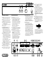
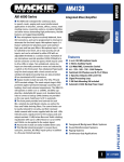
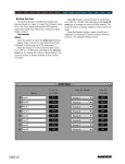
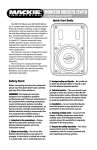
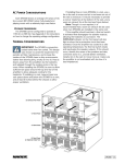
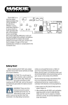
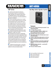
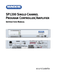
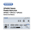
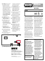
The STAND BY terminal is used to turn on
the amplifier with a remote switch.
Note: Standby mode must first be
activated by moving a jumper (J1) on the
input board (standby mode is disabled by
default). See Figure 1 on back page.
When the POWER switch is turned on, the
amplifier goes into standby mode. In this
state, the amplifier is on but signal is not
allowed to pass. Shorting the STAND BY
terminal with an
terminal to the GND
external switch causes the amplifier to
become fully operational.
The STANDBY GND terminal on the
COMMANDS terminal strip is the common
connection point for STAND BY.
The OVERL. 300mA terminal is active
whenever the amplifier's overload
protection circuit is activated. This
provides 18 VDC with a maximum output
capacity of 300mA for driving an auxiliary
relay or indicating LED.
The OVERL. GND terminal on the
COMMANDS terminal strip is the common
connection point for OVERL. 300mA.
AC Protection Fuse protects the power
supply and amplifier circuitry. Replace
only with same type fuse.
contained in the socket, behind the cover
located at the bottom of the socket.
Replace only with same type fuse.
UP4000 Series
Power Amplifier
The VOLTAGE SELECTOR switch is used to
select the AC supply voltage for the
amplifier. Move switch so the AC line
voltage used appears on the switch
(DOWN for 115V, UP for 230V).
Quick-Start Guide
UP 4161 - P.A. AMPLIFIER
STD-BY OVERLOAD SIGNAL
The H.P. switch activates a high-pass filter
on INPUTS 2-4, which attenuates
frequencies below 300Hz at 12 dB/octave.
The L.P. switch activates a low-pass filter
on INPUTS 2-4, which attenuates
frequencies above 7kHz at 12 dB/octave.
The UNBALANCED IN jack is an RCA-type
connector that can be used instead of the
BALANCED IN, or both can be used with
the PRIORITY function, which gives the
BALANCED IN priority over the
UNBALANCED IN.
The PARALLEL OUT jack is an RCA-type
connector that is in parallel with the
UNBALANCED IN jack for connecting to the
input of another power amplifier.
The SENSITIVITY switch adjusts the input
sensitivity of the UNBALANCED IN from 0
dB (typical line-level signals) to –20 dB
(for low-level signals).
Connect the supplied AC linecord to the
IEC AC Socket. The AC line fuse is
UP4000 SERIES
INPUT BOARD
JP6
J1
3
2
1
STANDBY ENABLED
STANDBY DISABLED
(DEFAULT)
Fig. 1: UP4000 Standby Mode Jumper (J1)
www.mackieindustrial.com
16220 Wood-Red Road NE, Woodinville, WA 98072 USA
TEL 888.337.7404, FAX 425.487.4337, [email protected]
UK +44.1268.571.212, FAX +44.1268.570.809 [email protected]
ITALY +39.0522.354.111, FAX +39.0522.926.208 [email protected]
FRANCE +33.3.8546.9160, FAX +33.3.8546.9161 [email protected]
GERMANY +49.2572.96042.0, FAX +49.2572.96042.10 [email protected]
Part No. 910-142-20 Rev. B 10/01
© 2001 Mackie Industrial. All Rights Reserved. Printed in U.S.A.
EQ
2
0
HIGH
2
2
4
4
6
0
4
2
4
8
-10
+10
6
8
8
-10
+10
5
ON
POWER
6
3
4
6 6
8
PEAK
VOLUME
LOW
7
2
8
1
9
0
10
The UP4000 Series Power Amplifiers are
designed for continuous duty in speech,
music, paging, and sound reinforcement
applications in churches, schools, offices, and
other venues demanding high performance,
flexible features, and rugged dependability.
Two discrete inputs with priority are
provided. The main program input is actively
balanced and terminated to a barrier strip
connection on the rear panel. The second
input is unbalanced and terminated to a
single RCA connector. A contact closure will
give priority to the balanced input by muting
the unbalanced input. The unbalanced input
features a parallel output and 0/–20 dB
sensitivity switch.
Output modes include 4Ω constant
impedance and 25V, 50V, 70V, and 100V
constant voltage. The smart output stage is
fully protected against permanent damage
caused by overloading, shorts, and extreme
temperatures. Activation of the overload
protection circuit turns on 18 VDC (300mA)
power at a barrier connector on the rear panel,
which may be used to drive LEDs or relays.
The UP4000 Series operates on either 115 VAC
or 230 VAC, 50/60Hz, as determined by the
Voltage Selector switch, and supplied by a
detachable IEC power cord. Insulated
terminals to connect a backup 24 VDC battery
are provided on the rear panel. Switchover to
DC is automatic. A programmable stand-by
mode allows the amplifier to be turned on
remotely with a contact closure.
The front panel provides a Master volume
control, and Low and High EQ controls. The
control knobs can be removed for security,
and their recessed shafts covered with the
supplied inserts. LEDs indicate power, standby mode, signal present at the output, peak,
and output overload. 12 dB/octave Low and
High shelving equalization with up to 12 dB of
boost or cut at 100Hz and 10kHz can be
applied to the output signal.
Accessories include a rack mounting kit.
Safety First!
1. Never install, connect, or disconnect
the unit with the power supply on.
2. Before powering up the UP4000 Series
amplifier, make sure the voltage
selector switch on the rear panel
corresponds to the AC voltage applied.
3. Make sure the safety ground on the
power cord is properly grounded.
4. To prevent the risk of electric shock,
never open the unit. There are no
user-serviceable parts inside.
5. To ensure normal cooling of the
UP4000 Series, make sure the unit is
well-ventilated. Avoid exposure to direct
sunlight or proximity to any heat
source, dust, or dampness.
6. If installed in an equipment rack, provide
at least one rack space between each
integrated amplifier.
Before connecting and using the
equipment, please read this Quick-Start Guide
carefully and keep it for future reference.
WARNING! This equipment has been
designed to be installed by qualified
professionals only! There are many factors to
be considered when installing professional
sound reinforcement systems, including
mechanical and electrical considerations, as
well as acoustic coverage and performance.
Mackie Industrial strongly recommends that
this equipment be installed only by a
professional sound installer or contractor.
CAUTION: To avoid the risk of electric
shock, never allow this equipment to
be exposed to rain or dampness.
The ground ( ) terminal is internally
connected to the chassis and safety
ground on the AC linecord.
UP 4161 - P.A. AMPLIFIER
STD-BY OVERLOAD SIGNAL
EQ
LOW
2
0
HIGH
2
2
4
4
6
0
4
2
4
4
6 6
8
-10
6
8
8
+10
8
-10
+10
5
LOW EQ is a shelving filter that provides
12 dB of boost and cut below 100Hz.
HIGH EQ is a shelving filter that provides
12 dB of boost and cut above 10kHz.
VOLUME is a master volume control used
to adjust the overall volume of the signal
at the POWER OUTPUTS.
Use the POWER switch to turn the UP4000
Series on and off.
The STD-BY indicator lights when the
amplifier is in standby mode.
Note: Standby mode is disabled by
default. An internal jumper (J1 on the
input board) must be changed to enable
standby mode. See Figure 1 on back page.
The OVERLOAD indicator lights when the
amplifier is operating in overload, a
condition generally caused by a problem
on the speaker line. When the amplifier is
switched on, the OVERLOAD light comes
on for a few seconds. This is normal and
does not indicate a problem.
The PRIORITY terminal activates the
priority function for the BALANCED IN by
using an external normally-open switch to
short-circuit the PRIORITY terminal to the
GND
(ground) terminal. When the
PRIORITY function is enabled, the
UNBALANCED IN is muted (no signal from
the UNBALANCED IN is transmitted to the
outputs).
Rear Panel Features
POWER
6
3
7
1
9
2
8
10
0
Front Panel Features
ON
PEAK
VOLUME
Constant-Impedance Output
The total impedance of the speakers and
cable connected to the "4Ω" constantimpedance output should be 4 ohms.
Connect the "4Ω" terminal to the "+"
(HIGH) speaker terminal, and the "0"
terminal to the "–" (LOW) speaker terminal.
POWER INPUT provides a means to
connect an external 24 VDC power supply
or battery as an alternative or backup
power source. The AM4000 Series
seamlessly switches to the backup supply
if there's an AC power loss. When both AC
power and 24 VDC power are connected,
the DC power is switched off.
The GND terminal is the common connection point for BALANCED IN and PRIORITY.
The BALANCED IN terminals are the main
inputs for the amplifier and accept a
balanced line-level signal (0 dBu nominal).
Connect signal high (+) and low (–) as
indicated below:
Constant-Voltage Output
In a constant-voltage system, each
speaker must be equipped with a line
transformer having an input voltage equal
to that of the line (e.g., 25V, 50V, 70V, or
100V). Typically, these line transformers
have selectable power taps (i.e., 2.5W,
5W, 10W) for connecting to the constantvoltage line. CAUTION: The sum of the
wattage values of the speakers must not
exceed the output power of the amplifier.
Note: The unit is not equipped with
battery charging capability.
The D.C. FUSE protects the DC POWER INPUT
circuit. Replace with the same type fuse only.
POWER OUTPUTS are screw-terminal
connections for connecting speakers to the
4-ohm, 25V, 50V, 70V, or 100V outputs.
–
PRIORITY
GND
BALANCED
IN
The BALANCED IN has a priority function,
and attenuates the UNBALANCED IN when
closing an external normally-open switch
connected between the PRIORITY terminal
to the GND (ground) terminal.
Connect the appropriate POWER OUTPUT
voltage terminal to the "+" (HIGH) leg and
the "0" terminal to the "–" (LOW) leg of the
distributed speaker system.
WARNING: To prevent the risk of electric
shock, never touch the bare wires coming
from the output terminals of the amplifier
when it is switched on. When all
connections have been made, insulate
the output terminals of the amplifier
using the protective cover provided.
+
When the OVERLOAD circuit is activated,
the OVERL. 300mA output on the
COMMANDS terminal strip is also activated.
The SIGNAL indicator lights when a signal
is present at the POWER OUTPUTS.
+
POWER INPUT
24V D.C.
-
D.C. FUSE
POWER OUTPUTS
POWER OUTPUTS
INPUT
COMMANDS
The PEAK indicator lights when the output
signal is approaching clipping.
0
The ON indicator lights when the AM4000
is turned on and ready for operation.
50V
70V
0
100V
4
25V
PRIORITY
STAND GND OVERL. GND
BY
300mA.
max
GND
BALANCED
IN
VOLTAGE
SELECTOR
CAUTION
RISK OF ELECTRIC SHOCK
DO NOT OPEN
REPLACE WITH THE SAME TYPE FUSE AND RATING.
DISCONNECT SUPPLY CORD BEFORE CHANGING FUSE
LINE
50/60 Hz-115/230V
WARNING: TO REDUCE THE RISK OF FIRE OR ELECTRIC SHOCK, DO NOT
PARALLEL OUT
FILTER
SERIAL NUMBER
MANUFACTURING DATE
EXPOSE THIS EQUIPMENT TO RAIN OR MOISTURE. DO NOT REMOVE COVER.
NO USER SERVICEABLE PARTS INSIDE. REFER SERVICING TO QUALIFIED PERSONNEL.
AVIS: RISQUE DE CHOC ELECTRIQUE — NE PAS OUVRIR
UNBALANCED IN
UTILISE UN FUSIBLE DE RECHANGE DE MÊME TYPE.
DEBRANCHER AVANT DE REMPLACER LE FUSIBLE
CONCEIVED, DESIGNED, AND MANUFACTURED BY MACKIE INDUSTRIAL • MADE IN ITALY • PATENTS PENDING • COPYRIGHT ©1999
THE FOLLOWING ARE TRADEMARKS/REGISTERED TRADEMARKS OF MACKIE DESIGN INC.: "MACKIE", "MACKIE INDUSTRIAL", & THE "RUNNING MAN" FIGURE
SENSITIVITY
L.P.
H.P.
OFF
20dB
ON
0dB