1
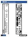
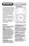
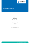
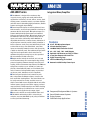
AMPLIFIER
AM4120
AM 4000 Series
Integrated Mixer/Amplifier
Features
■
■
■
■
■
■
■
■
■
4 Lo-Z, XLR Microphone Inputs
2 Stereo Auxiliary Inputs
120 Watt RMS, Convection Cooled
4Ω - 25V - 50V - 70V - 100V Outputs
Switched 24V Phantom and H-P/L-P Filters
2 Tape/Aux Outputs with Level Trim
Signal Processing Loop
2 RU Rack Mounting Kit included
Automatic 24Vdc Backup Power Input
■
■
■
■
Foreground/Background Music Systems
Sound Reinforcement Systems
Paging Systems
Continuous-duty Applications
1
APPLICATIONS
in speech, music, paging and sound reinforcement
applications in churches, schools, offices, arenas, hotel
meeting rooms, convention centers, recreation facilities
and other venues demanding high performance, flexible
features and rugged dependability.
■ Four microphone inputs are actively balanced, have
XLR connectors, and can be programmed to interrupt or
attenuate the line level inputs. Microphone inputs 2-4
feature switched 24V phantom power and switched
high-pass and low-pass filters. Microphone Input 1 can
be switched to line level, set to have priority over all
inputs, and can be activated by either VOX with an
adjustable threshold or a contact closure. Activation of
any microphone override provides 18Vdc (300mA) at a
barrier connector on the rear panel, which may be used
to drive LEDs or relays. Two unbalanced, stereo Aux
inputs are internally summed to mono and selected by
a switch on the front panel. Two unbalanced Tape (auxiliary) line level outputs with a level control and an
unbalanced signal processing loop are also provided.
All are terminated to RCA connectors.
■ Output modes include 4Ω and 25V, 50V, 70V and
100V constant voltage. The smart output stage is fully
protected against permanent damage caused by overloading, shorts and extreme temperatures. The AM4120
will operate on either 115 or 230VAC, 50/60Hz supplied by a detachable IEC power cord. Insulated terminals to connect a backup 24Vdc battery are provided
on the rear panel. Switchover to DC is automatic.
■ The front panel provides level controls for each
Mic, selected Aux and Master volume, as well as the
Bass and Treble shelving filters. The control knobs can
be easily removed for security, and their recessed
shafts covered with inserts supplied with the unit. LEDs
indicate power, signal present at the output, peak and
output overload. 12dB/octave Bass and Treble shelving
equalization with up to 12dB of boost or cut at 100Hz
and 10kHz can be applied to the output signal.
■ Accessories include an easily installed chime card.
■ This Mackie Industrial product is covered by an
exclusive, one-time, NO FAULT repair policy in addition
to a five year limited warranty.
AM4120
■ The AM4120 is designed for continuous duty
O FoF46 PAGES
PAGES
AMPLIFIER
AM4120
Integrated Mixer/Amplifier
Specifications
Power Supply
Performance
Amplifier Power:
120W, nominal,
180W peak (10mS)
50Hz–15kHz ±3dB
Less than 1% THD at
1kHz nominal power
Better than 65dB
AM4120
Frequency Response:
Distortion:
Noise:
Equalization
Output:
Treble shelving: ±12 dB at 10kHz
Bass shelving: ±12 dB at 100Hz
H-P filter: 12dB/oct. at 300Hz
L-P filter: 12dB/oct. at 7kHz
Inputs 2–4:
Audio Inputs
Microphones:
Three, active balanced XLR,
LoZ, 1.3mV, 24V phantom
powering with on-off switch
Microphone/Line:
One, active balanced XLR and
parallel barrier, switched mic/line;
Mic: LoZ, 1mV, Line: 80mV
Line Level:
Three, unbalanced, RCA connectors.
Two each, left and right (summed) Aux,
either pair selectable via
front-panel switch, 100mV;
One, Main (signal processing return), 775mV
115/230Vac (±5%), 50/60Hz,
450VA DC (24V battery) 10A/Hr
Environment
Maximum Ambient:
Physical
Dimensions (HxWxD):
Weight:
Finish:
131°F (55°C),
Non-precipitating humidity
3.46" x 17" x 12.4"
(88mm x 431mm x 314mm)
25.4lbs. (11.5kg)
Black painted or treated steel,
white nomenclature
Warranty
3 years, parts & labor
one-time no-fault repair policy
Accessories
A1708
RM4000
Three Chime Card
Rack Mounting Ears
Audio Outputs
Number of Channels:
Low Impedance:
Constant Voltage:
Line Level:
One
4Ω
25V, 50V, 70V, 100V
Barrier connectors
One, signal processing output, 2.5V, 600Ω
Two, tape (auxiliary) outputs 0–2.2V,
RCA connectors
Control Inputs & Outputs
DC Outputs:
Inputs:
Controls
Front Panel:
Rear Panel:
LED relay output, aux DC
output: 18Vdc (300mA)
activated by priority
Priority switch input, dry contact closure
barrier connectors
Power switch, master Volume,
Inputs 1–4,
Aux level, Aux 1/2 Switch,
Treble shelving, Bass shelving
Tape output level,
Voice priority threshold,
Chime output level (if installed),
24V phantom on/off switch,
H-P Filter in/out switch,
L-P Filter in/out switch,
Source Voltage Selector switch
2
O FoF46 PAGES
PAGES
3
2
O FoF46 PAGES
PAGES
1
3
0
4
7
8 2
3
4
10
9
1
0
6
10
5
5
6
INPUT 2
INPUT 1
9
7
8 2
1
3
0
4
5
6
10
INPUT 3
9
7
8 2
INPUT LEVELS
1
3
0
4
10
6
9
7
8 2
1
3
0
4
5
AUX
10
6
9
7
8
1
2
CONCEIVED, DESIGNED, AND MANUFACTURED BY MACKIE INDUSTRIAL • MADE IN ITALY
PATENTS PENDING • COPYRIGHT ©1999 • THE FOLLOWING ARE TRADEMARKS/REGISTERED
TRADEMARKS OF MACKIE DESIGN INC.: "MACKIE", "MACKIE INDUSTRIAL", & THE "RUNNING MAN" FIGURE
5
INPUT 4
AUX
6
8
4
-10
2
+10
2
8
4
6 6
8
4
MANUFACTURING DATE
0
LOW
EQ
-10
2
0
2
+10
HIGH
8
4
6
2
1
3
0
5
10
6
VOLUME
4
9
7
8
OVERLOAD SIGNAL
PEAK
POWER
ON
AM 4120 - P.A. AMPLIFIER
AM4120
Integrated Mixer/Amplifier
AMPLIFIER
AM4120
Integrated Mixer/Amplifier
AM4120
Architects’ and Engineers’ Specifications
The integrated mixer/amplifier shall have a nominal output power of at least 120W RMS. It shall operate on 115VAC
or 230VAC at either 50Hz or 60Hz and have its source power
supplied by a detachable IEC power cord. In addition the unit
shall be capable of being directly powered by a 24Vdc
source, such as storage batteries. It shall have a power
switch on the front panel. The unit shall have a constantimpedance output to drive a 4Ω load at its rated output. It
shall also have 25V, 50V, 70V and 100V constant-voltage outputs with like performance.
Inputs to the unit shall include: at least four actively balanced microphone; two unbalanced, stereo Aux; and an
unbalanced signal processing return. Outputs shall include:
at least two unbalanced Tape (auxiliary) jacks with a common, continuously variable level control; and one signal processing send. Balanced connections shall be made through
XLR connectors and unbalanced connections through RCA
connectors.
Microphone Input 1 shall have adjustable sensitivity
between mic and line, selected by a switch on the rear panel.
This input shall also be programmable to completely exclude
or attenuate all other inputs when its priority link is activated
by either a contact closure or a VOX circuit, with a continuously adjustable threshold. The XLR connector for Input 1
shall be wired, in parallel, to a barrier strip on the rear panel.
Microphone inputs 2-4 shall have a 24V phantom powering
circuit that can be disabled with a switch on the rear panel.
These inputs shall be equipped with a high-pass filter and a
low-pass filter having a response of 12dB/octave and fixed
–3db points at 300Hz and 7kHz, respectively. Each of these
filters shall be enabled by a switch on the rear panel.
Additionally, these inputs shall be programmable to completely exclude or attenuate all other inputs except for microphone input.
Two auxiliary voltage outputs shall be provided on the
rear panel to drive accessory relays and LEDs. The relay output shall deliver +18Vdc at 300mA. Voltage shall go high
when any microphone priority function is active.
The unit shall have, on its front panel, continuously variable controls for each microphone input, an auxiliary input
selector switch, a master volume control, as well as bass and
treble shelving filter controls. The shelving filters shall have a
range of ±12dB, with the frequency for the bass fixed at
100Hz and the treble fixed at 10kHz. LED status indicators
shall be provided on the front panel to indicate power, signal
present at the output terminals, peak signals near clipping
and an overload condition.
The integrated mixer/amplifier shall be a model AM4120,
manufactured by Mackie Industrial.
Electronic files for this product available at:
www.mackieindustrial.com
This Specification Sheet
Quick-Start Manual
Owner/Operator’s Manual
www.mackieindustrial.com
16220 Wood-Red Rd. NE, Woodinville, WA 98072 USA
888.337.7404, fax 425.487.4337, [email protected]
UK +44.1268.571.212, fax +44.1268.570.809, [email protected]
ITALY +39.0522.354.111, fax +39.0522.926.208, [email protected]
FRANCE +33.3.8546.9160, fax +33.3.8546.9161, [email protected]
GERMANY +49.2572.96042.0, fax +49.2572.96042.10, [email protected]
AM4120.PDF
AM4120QS.PDF
AM4120ML.PDF
Mackie Designs continually engages in research related to product improvement. New material, production methods, and design refinements are introduced into existing products without notice as a routine
expression of that philosophy. For this reason, any current Mackie Industrial product may differ in some
respect from its published description, but will always equal or exceed the original design specifications
unless otherwise stated. ©1999-2001 Mackie Designs Inc. All rights Reserved.
and
are
registered trademarks of Mackie Designs Inc. Mackie Industrial is a trademark of Mackie Designs Inc.
part no. 910-140-10 Rev.B
4
O FoF46 PAGES
PAGES