1
PIXMA iP5200
PIXMA iP5200R
SERVICE
MANUAL
Canon
Copyright 2005, Canon U.S.A. This technical publication is the proprietary and confidential information of Canon U.S.A. which
shall be retained for reference purposes by Authorized Service Facilities of Canon U.S.A. Its unauthorized use is prohibited.
issue a revised edition.
The following do not apply if they do not conform to the laws and regulations of the region where the manual
or product is used:
Trademarks
Product and brand names appearing in this manual are registered trademarks or trademarks of the respective
holders.
Copyright
All rights reserved. No parts of this manual may be reproduced in any form or by any means or translated into
another language without the written permission of Canon Inc., except in the case of internal business use.
Copyright © 2005 by Canon Inc.
CANON INC.
Inkjet Device Quality Assurance Div. 2
451, Tsukagoshi 3-chome, Saiwai-ku, Kawasaki-shi, Kanagawa 212-8530, Japan
I. MANUAL OUTLINE
This manual consists of the following three parts to provide information necessary to service the PIXMA
iP5200:
Part 1: Maintenance
Information on maintenance and troubleshooting of the PIXMA iP5200
Part 2: Technical Reference
New technology and technical information such as FAQ's (Frequently Asked Questions) of the PIXMA
iP5200
Part 3: Appendix
Block diagrams and pin layouts of the PIXMA iP5200
Reference:
This manual does not provide sufficient information for disassembly and reassembly procedures.
Refer to the graphics in the separate Parts Catalog.
II. TABLE OF CONTENTS
Part 1: MAINTENANCE
1. MAINTENANCE
1-1. Adjustment, Periodic Maintenance, Periodic Replacement Parts, and Replacement Consumables by
Service Engineer
1-2. Customer Maintenance
1-3. Product Life
1-4. Special Tools
1-5. Serial Number Location
2. LIST OF ERROR DISPLAY / INDICATION
2-1. Operator Call Errors
2-2. Service Call Errors
2-3. Warnings
2-4. Troubleshooting by Symptom
3. REPAIR
3-1. Notes on Service Part Replacement (and Disassembling / Reassembling)
3-2. Special Notes on Repair Servicing
3-3. Adjustment / Settings
(1) Paper feed motor adjustment
(2) Grease application
(3) Waste ink counter setting
(4) User mode
(5) Service mode
Destination settings
LF correction
3-4. Verification Items
(1) Service test print
(2) EEPROM information print
4. PRINTER TRANSPORTATION
Part 2: TECHNICAL REFERENCE
1. NEW TECHNOLOGIES
2. CLEANING MODE AND AMOUNT OF INK PURGED
3. PRINT MODE
4. FAQ (Problems Specific to the iP5200 and Corrective Actions)
Part 3: APPENDIX
1. BLOCK DIAGRAM
2. CONNECTOR LOCATION AND PIN LAYOUT
2-1. Logic Board Ass'y
2-2. Carriage Board (Print Head Connector)
PIXMA iP5200 Specifications
Part 1
MAINTENANCE
1. MAINTENANCE
1-1. Adjustment, Periodic Maintenance, Periodic Replacement Parts, and
Replacement Consumables by Service Engineer
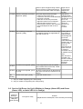
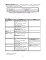
(1) Adjustment
Adjustment
Timing
Purpose
Tool
Approx.
time
Destination
settings
(EEPROM
settings)
At logic board replacement
To set the destination.
None.
Perform in the
service mode.
1 min.
Waste ink
counter
resetting
(EEPROM
settings)
- At logic board replacement
- At waste ink absorber
replacement
To reset the waste ink counter. None.
Perform in the
service mode.
1 min.
Paper feed
motor position
adjustment
At paper feed motor
replacement
To adjust the belt tension.
None.
(Position the paper feed motor
so that the belt is stretched
tight.)
5 min.
CD / DVD
detection
sensor light
volume
correction*1
- At logic board replacement To correct the light volume for
- At carriage unit replacement the CD / DVD detection
sensor.
Grease
application
- At carriage unit replacement - To maintain sliding properties FLOIL KG-107A
of the carriage shaft and the
- At PR shaft ass'y
lift cam shaft.
replacement
- To protect the printer's
- At CL base / gear
sliding portions (gears).
replacement
None.
Perform in the
service mode.
2 min.
1 min.
Ink system
- At logic board replacement To maintain detection
function check - At platen unit replacement
functionality for presence of
- At carriage unit replacement the ink tanks and each ink
tank position.
None.
Perform in the
service mode.
1 min.
LF correction
None.
Perform in the
service mode.
3 min.
- At feed roller replacement
- At logic board replacement
To correct the line feed
accuracy
Note: DO NOT loosen the red screws at both ends of the carriage shaft, securing the print head position, as
they are not re-adjustable.
The red screws securing the paper feed motor may be loosened only at replacement of the paper
feed motor unit.
*1: Only for CD / DVD printing supported regions.
(2) Periodic maintenance
No periodic maintenance is necessary.
(3) Periodic replacement parts
There are no parts in this printer that require periodic replacement by a service engineer.
(4) Replacement consumables
There are no consumables that require replacement by a service engineer.
1-1
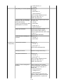
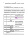
1-2. Customer Maintenance
Adjustment
Timing
Purpose
Tool
Approx.
time
Print head
alignment
At print head replacement.
To ensure accurate dot
placement.
- Printer buttons
- Computer
(automatic
settings via the
printer driver)
Print head
cleaning
When print quality is not
satisfying.
To improve nozzle
conditions.
- Printer buttons
1 min.
- Computer (settings
via the printer
driver)
Print head
deep cleaning
When print quality is not
satisfying, and not improved
by print head cleaning.
To improve nozzle
conditions.
Computer (settings
via the printer
driver)
Ink tank
replacement
When an ink tank becomes
empty. ("No ink error" via the
computer, or ink tank LED
flashing fast in red)
Paper feed
roller cleaning
When necessary
-----
-----
3 min.
2 min.
1 min.
To clean the paper feed
rollers.
Printer buttons
2 min.
CD / DVD print At CD / DVD printing, when
position
necessary
adjustment
To correct CD / DVD print
position.
Computer
(application
software)
5 min.
Bottom plate
cleaning
To clean the platen ribs.
- Plain paper
1 min.
- Computer (settings
via the printer
driver)
When the back side of the
paper is smeared
ASF sub- roller When the paper fed from the To clean the ASF subASF is smeared due to ink
cleaning
rollers.
mist attached to the ASF subrollers.
- Plain paper
1 min.
- Printer buttons
[See Part 2, 4. FAQ,
How to make and
set the ASF subroller cleaning
sheet, for details]
1-3. Product Life
(1) Printer
Specified print volume (I) or the years of use (II), whichever comes first.
(I) Print volume : 18,000 pages
Black
1,500 character pattern
1-2
8,300 pages
Color
A4, 7.5% duty per color pattern
5,400 pages
A4, photo, borderless printing
400 pages
4 x 6, photo, borderless printing
3,200 pages
Postcard, photo, borderless printing
700 pages
(II) Years of use
5 years of use
(2) Print head
Print volume : 18,000 pages
Black
1,500 character pattern
8,300 pages
Color
A4, 7.5% duty per color pattern
5,400 pages
A4, photo, borderless printing
400 pages
4 x 6, photo, borderless printing
3,200 pages
Postcard, photo, borderless printing
700 pages
(3) Ink tank (target value)
Pattern
Black text
Ink tank used
Print yield
PGI-5BK
Approx. 800 pages
PGI-5BK
Approx. 1,250 pages
CLI-8Y
Approx. 480 pages
CLI-8M
Approx. 500 pages
CLI-8C
Approx. 710 pages
CLI-8BK
Approx. 1,100 pages
CLI-8Y
Approx. 280 pages
CLI-8M
Approx. 250 pages
CLI-8C
Approx. 390 pages
Color chart
Photo chart
Black text: When printing the Canon standard pattern (1,500 characters per page) on A4 size plain
paper, with the default settings in the Windows XP driver, using Word 2003.
Color chart: When printing the ISO/JIS-SCID N5 pattern on A4 size plain paper in bordered printing, with
the default settings in the Windows XP driver, using Photoshop 7.0.
Photo chart: When printing the Canon standard pattern on 4" x 6" Photo Paper Plus Glossy in
borderless printing, with the default settings in the Windows XP driver, using Windows XP
Photo Printing Wizard.
The print yield in the table above is an average value measured in continuous printing, using the ink tank
1-3
immediately after it is unsealed, until the ink is out. Ink yield may vary depending on texts and photos
printed, application software, print mode, and type of paper used.
1-4. Special Tools
Name
Grease FLOIL
KG-107A
Tool No.
Application
Remarks
QY9-0057-000 To be applied to the sliding
In common with
portions of the carriage shaft and the S500 and
lift cam shaft.
S520.
1-5. Serial Number Location
On the carriage flexible cable holder (visible on the right of the carriage after the printer is turned on, the
access cover is opened, and the carriage moves to the center).
To the top
<Part 1: 1. MAINTENANCE>
1-4
2. LIST OF ERROR DISPLAY / INDICATION
Errors are indicated by the LED, and warnings are displayed on the monitor of the computer connected to
the printer.
2-1. Operator Call Errors (by Alarm LED Blinking in Orange)
Alarm
LED
blinking
in orange
2 times
3 times
4 times
5 times
Solution
Error [Error code]
No paper. (ASF) [1000]
Set the paper in the ASF, and press the
Resume/Cancel button.
No CD / DVD tray. [1001]*1
Set the CD / DVD tray, and press the
Resume/Cancel button.
No paper in the cassette.
[1003]
(No paper in the front paper
feed cassette.)
Set the paper in the cassette, and press
the Resume/Cancel button.
No CD / DVD disc. [1002]*1
Set a CD or DVD in the CD / DVD tray
(which is ejected at error occurrence),
and insert the CD / DVD tray in the
proper position. Then, press the
Resume/Cancel button.
Paper jam. [1300]
Remove the jammed paper, and press
the Resume/Cancel button.
Remarks
Error in paper
feeding from the
ASF.
Paper jam in the rear guide.
[1303]
Error in the
duplex printing
unit.
Paper jam in the under guide.
[1304]
Error in paper
feeding from the
cassette.
Front door close error. [1250]
Open the paper output tray.
No ink. [1600]
Replace the empty ink tank(s), or press Pressing the
the Resume/Cancel button.
Resume/Cancel
button will exit
the error without
ink tank
replacement,
however, ink
may run out
during printing.
Ink tank not installed. [1660]
Install the applicable ink tank(s)
properly, and confirm that the LED's of
all the ink tanks light red.
The print head is not installed ,
or it is not properly installed.
Install the print head properly.
1-5
The error is
indicated if the
paper output tray
is closed at start
of a print job, or
while a print job
is being
performed.
[1401]
Print head temperature sensor
error [1403]
Faulty EEPROM data of the
print head [1405]
Inner cover open. [1841]*2
Close the inner cover, and press the
Resume/Cancel button.
Inner cover open during
printing on paper. [1846]*2
Close the inner cover, and press the
Resume/Cancel button to clear the
error. The paper being printed at error
occurrence will be ejected without
printing the remaining data for the
ejected paper, then printing will resume
from the next page.
Inner cover open (print
continuable). [1851]*1
Close the inner cover, and press the
Resume/Cancel button.
Inner cover open during
printing on paper (print NOT
continuable). [1856]*1
Close the inner cover, and press the
Resume/Cancel button to clear the
error. The paper being printed at error
occurrence will be ejected without
printing the remaining data for the
ejected paper, then printing will resume
from the next page.
Inner cover closed during CD /
DVD printing (print
continuable). [1850]*1
Open the inner cover which functions
as the CD / DVD tray feeder, set the
CD / DVD tray in the feeder, and press
the Resume/Cancel button.
Inner cover closed during CD /
DVD printing (print NOT
continuable). [1855]*1
Open the inner cover, and press the
Resume/Cancel button to clear the
error. The CD or DVD being printed at
error occurrence will be ejected without
printing the remaining data for the
ejected CD or DVD, then the next print
job will be done.
Multiple ink tanks of the same
color installed. [1681]
Replace the wrong ink tank(s) with the
correct one(s).
Ink tank in a wrong position.
[1680]
Install the ink tank(s) in the correct
position.
8 times
Warning: The waste ink
absorber becomes almost full.
[1700]
Pressing the Resume/Cancel button will The service call
exit the error, and enable printing.
error, indicating
the waste ink
absorber is full,
is likely to occur
soon.
9 times
The connected digital camera
or digital video camera does
not support Camera Direct
Printing. [2001]
Remove the cable between the camera
and the printer.
6 times
7 times
10 times Automatic duplex printing
cannot be performed. [1310]
The size of paper may not be
compatible with automatic duplex
printing. Press the Resume/Cancel
1-6
Data which was
to be printed on
the back side of
button to eject the paper being used at
error occurrence. Printing will resume
from on the front side of the next page.
paper at error
occurrence is
skipped (not
printed).
11 times Failed in automatic print head
alignment. [2500]
Press the Resume/Cancel button.
- If paper is being fed at error
occurrence, the error is indicated after
the paper is ejected.
- If the error occurs, the print head
alignment values are not changed.
- After exit from the error by the
Resume/Cancel button, the automatic
print head alignment will not be redone.
The error is
indicated when
the pattern is not
printed due to no
ink or nonejection of ink, or
when the
sensor's AD
value is
incorrect.
13 times The remaining ink amount
unknown. [1683]
An ink tank which has once been empty Printing with a
is installed. Replace the applicable ink once-empty or
tank with a new one.
refilled ink tank
can damage the
print head.
If printing is
continued without
replacing the "nogood" ink tank,
press the
Resume/Cancel
button for 5 sec.
or longer to
record the use of
a refilled ink tank.
Note:
After the above
operation, the
function to detect
the remaining ink
amount is
disabled.
14 times Ink tank not recognized. [1684] A non-supported ink tank is installed
(the ink tank LED is turned off). Install
the supported ink tanks.
15 times Ink tank not recognized. [1410
to 1419]
An error occurred in an ink tank (the ink
tank LED is turned off). Replace the ink
tank(s).
No
blinking
Close the access cover.
Access cover open. [1200]
*1: Only for models supporting CD / DVD printing
*2: Only for models not supporting CD / DVD printing
2-2. Service Call Errors (by Cyclic Blinking in Orange (Alarm LED) and Green
(Power LED), or Alarm LED Lit in Orange)
Cycles of
blinking in
orange (Alarm
LED) and
green (Power
Error [Error code]
Solution
(Replacement of listed parts, which are likely to be faulty)
1-7
LED)
2 times
Carriage error [5100]
- Carriage unit (QM2-2251)
- Timing slit strip film (QC1-6526)
- Logic board ass'y (QM2-2733)*1
- Carriage motor (QK1-1500)
3 times
Line feed error [6000]
- Timing sensor unit (QM2-2683)
- Timing slit disk film (QC1-6229)
- Feed roller ass'y (QL2-0950)
- Platen unit (QM2-2248)
- Logic board ass'y (QM2-2733)*1
- PAPER FEED MOTOR (QK1-1502)
4 times
Purge cam sensor error
[5C00]
- Purge unit (QM2-2252)
- Logic board ass'y (QM2-2733)*1
5 times
ASF (cam) sensor error
[5700]
Internal temperature error
[5400]
Waste ink absorber full
[5B00]
- Sheet feed unit (QM2-2278)
6 times
7 times
- Logic board ass'y (QM2-2733)*1
- Ink absorber kit (QY5-0152)
8 times
Print head temperature rise - Print head (QY6-0059)
error [5200]
- Logic board ass'y (QM2-2733)*1
9 times
EEPROM error [6800]
- Logic board ass'y (QM2-2733)*1
11 times
Carriage lift mechanism
error [5110]
- PR lift shaft ass'y (QL2-0936)
- Sheet feed unit (QM2-2278)
- Logic board ass'y (QM2-2733)*1
- Carriage lift sensor unit (QM2-2678)
12 times
AP position error [6A00]
- Sheet feed unit (QM2-2278)
- Logic board ass'y (QM2-2733)*1
- Purge unit (QM2-2252)
13 times
Paper feed position error
[6B00]
- Sheet feed unit (QM2-2278)
- Logic board ass'y (QM2-2733)*1
14 times
Paper feed cam sensor
error [6B10]
- Sheet feed unit (QM2-2278)
- Logic board ass'y (QM2-2733)*1
15 times
USB Host Vbus over
current [9000]
- Logic board ass'y (QM2-2733)*1
16 times
Valve sensor error [6C00]
- Logic board ass'y (QM2-2733)*1
- Purge unit (QM2-2252)
17 times
Motor driver error [6D00]
- Logic board ass'y (QM2-2733)*1
19 times
Ink tank position sensor
error [6502]
- Platen unit (QM2-2248)
- Logic board ass'y (QM2-2733)*1
20 times
Other hardware error
- Logic board ass'y (QM2-2733)*1
1-8
Continuous
alternate
blinking
Alarm LED lit
[6500]
ROM error
- Logic board ass'y (QM2-2733)*1
RAM error
- Logic board ass'y (QM2-2733)*1
*1: Before replacement of the logic board ass'y, check the waste ink amount (by service test print or
EEPROM information print). If the waste ink amount is 7% or more, also replace the ink absorber kit
(QY5-0152) when replacing the logic board ass'y.
[See Section 3-3. Adjustment / Settings, (5) Service mode, for details.]
2-3. Warnings
Printer (no LED indications):
Displayed warning
Low ink
Remarks
- Status monitor indication.
- The ink tank lamp flashes slowly (at about a second interval).
Print head temperature rise
If the print head temperature is high when the access cover is
opened, the warning is displayed*1.
When the print head temperature falls, the warning is released.
Protection of excess rise of the print If the print head temperature exceeds the specified limit, a Wait
head temperature
is inserted during printing,
*1: If the warning is displayed, the carriage does not move to the ink tank replacement position when the
access cover is opened.
2-4. Troubleshooting by Symptom
Symptom
Faulty operation
Paper feed
problems
Solution
The power does not turn on.
The power turns off
immediately after power-on.
Replace the
- AC adapter, or
A strange noise occurs.
Remove foreign material, or attach a
removed part if any.
Printing stops mid-way.
Replace the logic board ass'y*1.
Multiple sheets feed.
Replace the
- sheet feed unit, or
- cassette.
Paper does not feed.
Remove foreign material, or replace
the
- sheet feed unit, or
- cassette.
Paper feeds at an angle.
Remove foreign material, adjust the
paper guide, or replace the
- logic board ass'y*1.
1-9
Remarks
- sheet feed unit, or
- cassette.
No printing, or no color ejected. Replace the
- ink tank,
- print head*2, or
- logic board ass'y*1,
remove foreign material from the
purge unit caps, if any, or
replace the purge unit.
Printing is faint, or white lines
appear on printouts even after
print head cleaning.
Line(s) not included in the print
data appears on printouts.
Remove and re-install the print head,
or replace the
- ink tank,
- print head*2,
- purge unit, or
- logic board ass'y*1.
Paper gets smeared.
Feed several sheets of paper,
perform bottom plate cleaning,
clean the paper path with cotton swab
or cloth, or
clean the ASF sub-rollers.
A part of a line is missing on
printouts.
Replace the
- ink tank, or
- print head*2.
Unsatisfactory
print quality
Color hue is incorrect.
Replace the
- ink tank, or
- print head*2, or
perform print head alignment.
Printing is incorrect.
Replace the logic board ass'y*1.
No ejection of black ink.
Replace the
- ink tank, or
- print head*2, or
remove foreign material from the
purge unit caps, if any, or
replace the purge unit.
Graphic or text is enlarged on
printouts.
When enlarged in the carriage
movement direction, clean grease or
oil off the timing slit strip film, or
replace the
- timing slit strip film,
- carriage unit, or
- logic board ass'y*1.
When enlarged in the paper feed
direction, clean grease or oil off the
timing slit disk film, or replace the
1-10
- timing slit disk film,
- timing sensor unit, or
- logic board ass'y*1.
Uneven printing due to line
feeding
Perform LF correction adjustment.
*1: Before replacement of the logic board ass'y, check the waste ink amount (by service test print or
EEPROM information print). If the waste ink amount is 7% or more, also replace the ink absorber kit
(QY5-0152) when replacing the logic board ass'y.
[See Section 3-3. Adjustment / Settings, (5) Service mode, for details.]
*2: Replace the print head only after the print head deep cleaning is performed 2 times, and when the
problem persists.
To the top
<Part 1: 2. LIST OF ERROR DISPLAY / INDICATION>
1-11
3. REPAIR
3-1. Notes on Service Part Replacement (and Disassembling / Reassembling)
Notes on replacement*1
Adjustment / settings
- Before removal of the
logic board ass'y,
remove the power cord,
and allow for approx. 1
minute (for discharge of
capacitor's accumulated
charges), to prevent
damages to the logic
board ass'y.
- Before replacement,
check the waste ink
amount (by service test
print or EEPROM
information print). If the
waste ink amount is 7%
or more, also replace the
ink absorber kit when
replacing the logic board
ass'y.
[See 3-3. Adjustment /
Settings, (5) Service
mode, for details.]
After replacement:
1. Initialize the EEPROM.
2. Reset the waste ink
counter.
3. Set the destination in
the EEPROM.
4. Correct the CD / DVD
and automatic print
head alignment
sensors.
5. Check the ink system
function.
[See 3-3. Adjustment /
Settings, (5) Service
mode, for details of 1 to 5]
6. Perform the print head
alignment in the user
mode.
- EEPROM information
print
- Service test print
- Printing via USB
connection
- Direct printing from a
digital camera
Ink absorber kit
QY5-0152
After replacement:
1. Reset the waste ink
counter.
[See 3.3. Adjustment /
Settings, (5) Service
mode.]
- Service test print
Carriage unit
QM2-2251
At replacement:
1. Apply grease to the
sliding portions.
[See 3-3. Adjustment /
Settings, (2) Grease
application.]
After replacement:
1. Correct the CD / DVD
and automatic print
head alignment
sensors.
[See 3.3. Adjustment /
Settings, (5) Service
mode.]
2. Check the ink system
function.
[See 3.3. Adjustment /
Settings, (5) Service
mode.]
- Service test print
(Confirm CD / DVD
and automatic print
head alignment sensor
correction, and ink
system function.)
Service part
Logic board ass'y
QM2-2733
3. Perform the print head
alignment in the user
mode.
Paper feed motor
QK1-1502
- The red screws securing At replacement:
the paper feed motor are 1. Adjust the paper feed
allowed to be loosened.
motor.
(DO NOT loosen any
1-12
Operation check
- EEPROM information
print
other red screws.)
Platen unit: QM22248
Purge unit: QM22252
Waste ink tube:
QC1-6458
Waste ink tube
holder: QC1-6460
[See 3-3. Adjustment /
Settings, (1) Paper feed
motor adjustment.]
- By attaching the tape at At replacement:
the specified 2 locations, 1. To protect the waste
secure the waste ink
ink tube from being
tube to the waste ink
pinched when
tube holder.
reassembling the
printer unit chassis into
the bottom case unit,
tape the tube (at 2
locations).
[See 3-2. Special Notes
on Repair Servicing, (3)
Printer unit and bottom
case unit assembly.]
After the printer unit is
assembled in the bottom
case unit, the tube
conditions are not
visible. For confirmation
of the tube conditions,
perform the manual
purging 3 or 4 times,
and confirm that no
strange noise is heard.
Platen unit
QM2-2248
After replacement:
1. Check the ink system
function.
[See 3-3. Adjustment /
Settings, (5) Service
mode.]
- Service test print
PR lift shaft ass'y
QL2-0936
CL INPUT GEAR
QC1-6213
At replacement:
1. Apply grease to the
sliding portions.
[See 3.3. Adjustment /
Settings, (2) Grease
application.]
- Service test print
After replacement:
1. Perform the print head
alignment in the user
mode.
- Service test print
After replacement:
1. Perform the print head
alignment in the user
mode.
- Service test print
Timing slit strip film
QC1-6526
Timing slit disk film
QC1-6229
Print head
QY6-0061
- Upon contact with the
film, wipe the film with
ethanol.
- Confirm no grease is on
the film. (Wipe off any
grease thoroughly with
ethanol.)
- Do not bend the film
*1: General notes:
- Make sure that the flexible cables and wires in the harness are in the proper position and
connected correctly.
[See 3-2. Special Notes on Repair Servicing, (2) Flexible cable and harness wiring, connection, for
details.]
- Protect the waste ink tube from being pinched when assembling the printer unit chassis into the
bottom case unit.
Since the tube conditions after assembly are not visible, perform the manual purging 3 or 4 times
to confirm that no strange noise is heard.
[See 3-2. Special Notes on Repair Servicing, (3) Printer unit and bottom case unit assembly, for
details.]
1-13
- Do not drop the ferrite core, which may cause damage.
- Protect electrical parts from damage due to static electricity.
- Before removing a unit, after removing the power cord, allow the printer to sit for approx. 1 minute
(for capacitor discharging to protect the logic board ass'y from damages).
- Do not touch the timing slit strip film and timing slit disk film. No grease or abrasion is allowed.
- Protect the units from soiled with ink.
- Protect the housing from scratches.
- Exercise caution with the red screws, as follows:
i. The red screws of the paper feed motor may be loosened only at replacement of the paper
feed motor unit (DO NOT loosen them in other cases).
ii. DO NOT loosen the red screws on both sides of the main chassis, securing the carriage
shaft positioning (they are not adjustable in servicing).
To the top
<Part 1: 3. REPAIR, 3-1>
1-14
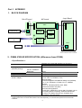
3-2. Special Notes on Repair Servicing
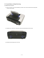
(1) External cover removal
(I) With your fingers at the points indicated by the blue circle, raise and slide the left and right side
covers to remove them.
(II) Release the 2 hooks on the rear side of the printer (indicated by the blue circles).
(III) Slide the left and right panel cover units.
1-15
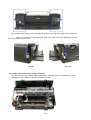
(IV) Hold the left and right corners indicated by the blue circle, and lift the upper case to remove it.
Note: In removing or re-assembling the upper case, make sure not to damage the ink tank
sensor and ink tank sensor cover.
Left side
Right side
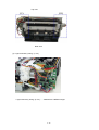
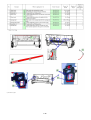
(2) Flexible cable and harness wiring, connection
Be careful of wiring of the flexible cables and harness. Improper wiring or connection may cause
breakage of a line, leading to ignition or emission of smoke.
1-16
Top view
Rear view
(I) Logic board ass'y wiring (1 of 2)
Logic board ass'y wiring (2 of 2)........Viewed from a different angle
1-17
(II) Paper feed motor side wiring
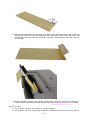
(3) Printer unit and bottom case unit assembly
In assembling the printer unit chassis into the bottom case unit, be cautious of the following points to
protect the waste ink tube from being pinched:
(I) At replacement of the platen unit (QM2-2248), purge unit (QM2-2252), waste ink tube (QC1-6458), or
waste ink tube holder (QC1-6460), fix the waste ink tube to the printer chassis and waste ink tube
holder with tape (at 2 locations).
If the tube is pinched and blocked, proper purging is prevented, resulting in ink leakage or strange
noise.
(No specific tape is specified. In the sample photo below, (1) is the orange tape, and (2) is a clear
adhesive tape, such as Sellotape or Scotch tape.)
1-18
(II) After securing the waste ink tube with tape, be careful not to damage the tube in installing the printer
unit chassis in the bottom case unit.
With the units assembled, the tube conditions are not visible. To confirm the tube is free from
damage, perform the manual purging 3 or 4 times, and confirm that no strange noise is heard.
[Example: The tube is pinched and blocked as it is not fixed with tape.]
1-19
To the top
<Part 1: 3. REPAIR, 3-2>
1-20
3-3. Adjustment / Settings
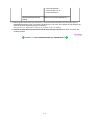
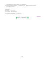
(1) Paper feed motor adjustment
Perform the following adjustments when the paper feed motor unit is replaced:
1) When attaching the motor, fasten the screws so that the belt is properly stretched (in the direction indicated by the blue arrow in the figure below).
2) After replacement, be sure to perform the service test print, and confirm that no strange noise or faulty print operation (due to dislocation of the belt or gear, or out-of-phase motor, etc.) occurs.
Note: The red screws securing the paper feed motor may be loosened only at replacement of the paper feed motor unit. DO NOT loosen them in other cases.
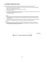
(2) Grease application
1) Printer unit
1-21
2) CL base / CL gear
1-22
3) PR shaft / LF roller bushing
To the top
<Part 1: 3. REPAIR, 3-3 (1) to (2)>
1-23
(3) Waste ink counter setting
When the logic board ass'y is replaced, reset the waste ink counter. In addition, according to the waste
ink amount, replace the waste ink absorber (ink absorber kit). The standard amount for waste ink
absorber replacement is given in the table below.
Waste ink amount*1
Ink absorber kit replacement
Less than 7%
Not required.
7% or more
Required.
*1: Check the waste ink amount by service test print or EEPROM information print.
[See 3.3. Adjustment / Settings, (5) Service mode, for details.]
(4) User mode
Function
Print head manual
cleaning
Procedures
Remarks
- Cleaning both black and color:
See "Standalone printer operation"
below.
- Cleaning black or color separately, or
both black and color:
Perform from the printer driver
Maintenance tab.
Print head deep cleaning - Cleaning black or color separately, or
both black and color:
Perform from the printer driver
Maintenance tab.
Paper feed roller
cleaning
See "Standalone printer operation"
below.
Nozzle check pattern
printing
- See "Standalone printer operation"
below.
- Perform from the printer driver
Maintenance tab.
Print head alignment
- See "Standalone printer operation"
below.
- Perform from the printer driver
Maintenance tab.
(Automatic head alignment, Manual
head alignment)
Bottom plate cleaning
Perform from the printer driver
Maintenance tab.
Print head replacement
The print head is replaceable at the
same position as for ink tank
replacement. (Open the access cover.
When the carriage stops at the center,
the print head can be replaced.)
<Standalone printer operation>
1) Turn on the printer.
1-24
In Custom Settings of the printer
driver Maintenance tab, manual
print head alignment (by
selecting the optimum values) as
with the conventional models can
be performed.
Cleaning of the platen ribs when
the back side of paper gets
smeared.
2) Press and hold the Resume/Cancel button until the Power LED blinks in green the specified number
of times listed in the table below, and release it. The operation starts.
Power LED
blinking
Operation
Remarks
1 time
Print head manual cleaning
2 times
Nozzle check pattern printing
3 times
Paper feed roller cleaning
4 times
Automatic print head alignment
Set a sheet of plain paper (A4 or letter) in the ASF.
5 times
Bottom plate cleaning
Fold a sheet of plain paper (A4 or letter) in half
crosswise, then unfold and set it in the ASF with
the folded ridge facing down.
6 times
Unspecified
7 times
The widest head-to-paper
distance setting
8 times or
more
Unspecified
Set a sheet of plain paper (A4 or letter) in the ASF
or the cassette (according to the Paper Feed
switch setting).
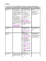
(5) Service mode
Function
Service test print
- Model name
- Destination
- ROM version
- USB serial number
- Waste ink amount
- CD / DVD sensor
correction value
Procedures
Remarks
See "Service mode operation
procedures" below.
Set a sheet of A4 or letter size paper.
For print sample, see 3-4. Verification
Items, (1) Service test print, <Service
test print sample>.
EEPROM initialization
See "Service mode operation
procedures" below.
The following items are NOT
initialized, and the shipment arrival
flag is not on:
- USB serial number
- Destination settings
- Waste ink counter
- CD / DVD correction value
Waste ink counter
reset
See "Service mode operation
procedures" below.
If the waste ink amount is 7% or more,
replace the ink absorber kit.
Destination settings
See "Service mode operation
procedures" below.
- Ink system function
check result
- CD / DVD sensor
correction result
1-25
Note: At the end of the service mode, press the Power button. To protect the media sensor from being
dislocated during transportation, the paper lifting plate of the sheet feeder unit will be raised.
<Service mode operation procedures>
1) With the printer power turned off, while pressing the Resume/Cancel button, press and hold the
Power button. (DO NOT release the buttons. The Power LED lights in green to indicate that a
function is selectable.)
2) While holding the Power button, release the Resume/Cancel button. (DO NOT release the Power
button.)
3) While holding the Power button, press the Resume/Cancel button 2 times, and then release both the
Power and Resume/Cancel buttons. (Each time the Resume/Cancel button is pressed, the Alarm and
Power LEDs light alternately, Alarm in orange and Power in green, starting with Alarm LED.)
4) When the Power LED lights in green, press the Resume/Cancel button the specified number of time
(s) according to the function listed in the table below. (Each time the Resume/Cancel button is
pressed, the Alarm and Power LEDs light alternately, Alarm in orange and Power in green, starting
with Alarm LED.)
Time(s)
LED indication
0 times
Green (Power) Power off
When the print head is not installed, the
carriage returns and locks in the home
position capped.
1 time
Orange (Alarm) Service test print
See 3-4. Verification Items, (1) Service
test print.
2 times
Green (Power) EEPROM information See 3-4. Verification Items, (2) EEPROM
information print.
print
3 times
Orange (Alarm) EEPROM initialization
4 times
Green (Power) Waste ink counter
resetting
5 times
Orange (Alarm) Destination settings
6 times
Green (Power) Print head deep
cleaning
(Cleaning of both black and color)
7 times
Orange (Alarm) LF correction
8 times
Green (Power) CD / DVD check
pattern print
Not used in servicing.
9 times
Orange (Alarm) CD / DVD print
position correction
(horizontal: X
direction)
Not used in servicing.
Green (Power) CD / DVD print
position correction
(vertical: Y direction)
Not used in servicing.
10 times
Function
Remarks
After entering the destination settings
mode, press the Resume/Cancel button
the specified number of time(s) to select
the destination. For detail, see
"Destination settings procedures" below.
11 to 13
times
Orange, Green, Return to the menu
Orange
selection
(Alarm, Power,
Alarm)
14 times
Green (Power) Left margin correction Not used in servicing.
1-26
15 times
Orange (Alarm) Return to the menu
selection
Note: If the Resume/Cancel button is pressed 16 or more times, the Alarm or Power LED lights steadily
without any changes.
<Destination settings procedures>
In the destination settings mode, press the Resume/Cancel button the specified number of time(s)
according to the destination listed in the table below, and press the Power button.
Time(s)
LED indication
Destination
CD / DVD print
0 times
Green (Power) No change of the destination
1 time
Orange (Alarm) Japan
Supported
2 times
Green (Power) Korea
Not supported
3 times
Orange (Alarm) US
Not supported
4 times
Green (Power) Europe
Supported
5 times
Orange (Alarm) Australia
Supported
6 times
Green (Power) Asia
Supported
7 times
Orange (Alarm) China
Supported
8 times
Green (Power) Taiwan
Supported
9 times
Orange (Alarm) Return to the Destination setting mode
Note: After setting the destination, confirm the model name and destination in service test
print or EEPROM information print.
[See 3.4. Verification Items, (1) Service test print, or (2) EEPROM information print.]
<LF correction procedures>
Purpose: After replacement of the feed roller ass’y or logic board ass’y in repair servicing or in rebox
operation, adjust the line feeding in the same way as done at the production site.
Operation: Print the LF correction pattern, and select the Pattern No. from 0 to 2 which contains the
least streaks or lines. Press theResume/Cancel button the same number of times as the
selected Pattern No., and press the Power button. The LF correction will be done.
Procedures:
1) In the LF correction mode, press the Resume/Cancel button the specified number of times according
to the paper to be used in LF correction listed in the table below, then press the Power button.
Time(s)
Paper Type
1 time
High Resolution Paper
Canon HR-101
Canon PB Paper GF-500 (64g/m2)
Canon Office Planner
2 times
3 times
Paper name
Plain paper
HP BrightWhite (90g/m2)
Canon Office (80g/m2)
Canon Extra (80g/m2)
STEINBEIS Vision Classic White
4 times
1-27
Note:
- The High Resolution Paper is the most desirable for LF correction printing (Canon HR-101 is
used at the production site), but 6 kinds of plain paper listed in the table above can also be
used in LF correction. If plain paper other than the above is used, select any one of the
paper types in this step, then select Pattern No. 0 (zero) in the step 3) below.
- Each time the Resume/Cancel button is pressed, the Alarm and Power LEDs light
alternately, alarm in orange and Power in green.
- If the Resume/Cancel button is NOT pressed, and only the Power button is pressed, the
printer remains in the LF correction mode.
- If the Resume/Cancel button is pressed 5 times or more, then the Power button is pressed,
the printer returns to the service mode menu selection.
2) The LF correction pattern for the selected paper is printed.
LF correction pattern print sample:
3) In the printout, select the Pattern No. in which streaks or lines (white or black) are the least
noticeable, press the Resume/Cancel button the same number of time(s) as the selected Pattern No.,
then press the Power button.
Pattern No.
Number of times the Resume/Cancel button is pressed
1
1
0
0
2
2
1-28
Note:
- If plain paper other than the 6 kinds specified in the table in step 1) is used, select the
Pattern No. 0 (zero), leave the Resume/Cancel button untouched, and press the Power
button.
- Each time the Resume/Cancel button is pressed, the Alarm and Power LEDs light
alternately, alarm in orange and Power in green.
- If the Resume/Cancel button is pressed 3 times or more, then the Power button is pressed,
the printer returns to the service mode menu selection.
NG : streaks or lines (white or black)
4) The LF correction value is written to the EEPROM, and the printer returns to the service mode menu
selection.
Note: The LF correction value (0, 1, or 2) can be confirmed in service test print or EEPROM
information print.
To the top
<Part 1: 3. REPAIR, 3-3 (3) to (5)>
1-29
3-4. Verification Items
(1) Service test print
<EEPROM information contents>
On the service test print (sample below), confirm the EEPROM information as shown below. (The
information is given in the upper portion of the printout.)
iP5200: Model name
US: Destination
Vx.xx: ROM version
USB (xxxxxx): USB serial number
FA = xx xx xx: Reserved for plant use
D = xxx.x: Waste ink amount (%)
CDR (+xxxxx, +yyyyy): CD / DVD sensor position correction value
LF = (x): LF correction value
AB (K = OK
Y = OK ...): Ink system check result
<Print check items>
On the service test print (sample below), confirm the following items:
- Check 1,
top of form accuracy: The lines shall not extend off the paper.
- Check 2,
EEPROM information
- Check 3,
nozzle check pattern: Ink shall be ejected from all nozzles.
- Check 4, check pattern for uneven printing due to line feeding: There shall be no remarkable
streaks or unevenness.
- Check 5,
LF correction pattern: There should be no white line and black line.
- Check 6, check pattern for uneven printing due to carriage movement (9600 dpi mode):
There shall be no remarkable unevenness.
- Check 7, check pattern for uneven printing due to carriage movement (standard mode):
There shall be no remarkable unevenness.
- Check 8, CD / DVD sensor and automatic print head alignment sensor correction: The results
shall be OK.
<Service test print sample>
1-30
(2) EEPROM information print
<How to read EEPROM information print>
Print sample:
iP5200 US V1.01 IF(USB2=1) D=004.5 ST=2005/05/27-18:30
ER(ER0=1000 ER1=5100) LPT=2005/07/07-09:09
PC(M=002 R=000 T=001 D=009 C=008)
CLT(BK=2005/07/02-18:30 CL=2005/07/01-18:30)
CH=00002 CT(PBK=001 BK=010 Y=009 M=001 C=003) IS(PBK=0 BK=0 Y=0 M=0 C=0)
P_ON(S=00009) A_REG=1 M_REG=1
1-31
UR(A(BKoe)=000 B(Coe)=000 C(Moe)=000 D(SCoe)=000 E(SMoe)=000 F(PBKoe)=000
G(CLbi)=000 H(SCLbi)=000 I(C-SC)=000 J(M-SM)=000 K(BK-CL)=000
L(BKbiPP)=000 M(CLbiPP)=000 N(SCLbiPP)=000 O(NZctr)=000 P(NZedge)=000
WP=0008 CDIN(LG=001 PB=000) MSD(005)
TPAGE=00085
PAGE(All=00083 PP=00035 HR+MP=00003 PR+SP+SG=00000 GP=00000 PC=00000 EV=00000)
UCPAGE(All=00083 PP=00035 HR+MP=00003 PR+SP+SG =00000 GP =00000 PC=00000
EV=00000)
BPPAGE(All=00083 BSSP=00003 PC=00000)
CDPAGE(All=000) EDGE=00083 L=00000 CDR=00000
CDRP=(-00005,-00029) CDRS=(190) LF=0 LM=(ASF_R:00 UT_F:00 UT_R:00)
Head TempBK=30.5 Head TempC=29.5 Env Temp=28.5
FF(A0 45 11)
HDEEPROM
V0001 SN=0318-A43D
LN(00000 00000 00001 00003 00001 00017 00015) ID=09
IL=(PBK=000 BK=000 Y=001 M=001 M2=001 C=000 C2=001)
Printed items:
1. Model name 2.Destination 3. ROM version 4. Connected I/F (USB2) 5. Waste ink amount 6.
Installation date
7. Operator call/service call error record
8. Last printing time
9. Purging count (manual/deep cleaning/timer/dot count/ink tank replacement)
10. Cleaning time (BK/CL)
11. Print head replacement count
(PBK/BK/Y/M/C)
12. Ink tank replacement count (PBK/BK/Y/M/C) 13. Ink status
14. Power-on count (soft) 15. Automatic print head alignment by user 16. Manual print head alignment
by user
17. User print head alignment values (BKoe/Coe/Moe/SCoe/SMoe/PBKoe
/CLbi/SCLbi/C-SC/M-SM/BK-CL
/BKbiPP/CLbiPP/SCLbiPP/NZctr/NZedge)
18. Wiping count 19. Camera Direct Print-supported device connection record 20. Longest period
where printing stops
21.Total feed pages
22. ASF feed pages (total, plain paper, High Resolution Paper & Matte Photo Paper,
Photo Paper Pro & Photo Paper Plus Glossy & Photo Paper Plus Semi-gloss, Glossy Photo Paper,
Postcard, Envelope)
23. U-turn cassette feed pages (total, plain paper, High Resolution Paper & Matte Photo Paper,
Photo Paper Pro & Photo Paper Plus Glossy & Photo Paper Plus Semi-gloss, Glossy Photo Paper,
postcard, envelope)
24. Auto duplex print pages (total, Photo Paper Plus Double Sided, postcard)
25. Camera Direct print pages (total)
of CDs and DVDs printed
29. CD / DVD print position adjustment
32. Left margin correction
26. Borderless print pages 27. L & 4x6 print pages
28. Number
30. CD / DVD sensor correction value 31.LF correction value
1-32
value (ASF back side, U-turn front side, U-turn back side)*1
33. Print head temperature (BK/CL)
34. Inside temperature 35. Line inspection information
*1: not used for servicing
HDEEPROM
36. Version
37. Serial number
38. Lot number
39. Print head ID
40. Ink ejection level (PBK, BK, Y, M, M2, C, C2)
To the top
<Part 1: 3. REPAIR, 3-4>
1-33
4. PRINTER TRANSPORTATION
This section describes the procedures for transporting the printer for returning after repair, etc.
1) In the service mode, press the Power button to finish the mode, and confirm that the paper lifting
plate of the sheet feeder unit is raised.
2) Keep the print head and ink tanks installed in the carriage.
[See Caution 1 below.]
3) Turn off the printer to securely lock the carriage in the home position. (When the printer is turned off,
the carriage is automatically locked in place.)
[See Caution 2 below.]
Caution:
(1) If the print head is removed from the printer and left alone by itself, ink (especially the pigment
black ink) is likely to dry. For this reason, keep the print head installed in the printer even during
transportation.
(2) Securely lock the carriage in the home position, to prevent the carriage from moving and applying
stress to the carriage flexible cable, or causing ink leakage, during transportation.
Memo:
If the print head must be removed from the printer and transported alone, perform the following:
(1) Attach the protective cap (used when the packing was opened) to the print head (to protect the
print head face from damage due to shocks).
To the top
<Part 1: 4. PRINTER TRANSPORTATION>
1-34
Part 2
TECHNICAL REFERENCE
1. NEW TECHNOLOGIES
(1) New ink tank system (PGI-5BK, CLI-8 series)
The PIXMA iP5200 utilizes a high-density print head through the FINE technologies, supporting 1 pl
ultra-small ink droplets, to achieve the 9,600 dpi super-photo print quality. It is the premium photo
printer offering high-speed and high quality premium photo printing with multi-paper path functionality.
The new ink tanks, PGI-5BK (pigment-based BK) and CLI-8 series (dye-based BK, C, M, and Y),
have an LED to prevent wrong installation of the ink tanks, and allow users to recognize the
remaining ink level with the ink tanks seated in the carriage.
(2) Premium photo printing
By the FINE technologies, 1 pl of ultra-fine ink droplet is adopted. The iP5200 provides excellent
premium photo print quality without graininess at the maximum resolution of 9,600 dpi x 2,400 dpi*1.
*1: Printing at the minimum distance of 1/9600 inch between the dots.
(3) Print speed
Borderless 4" x 6" photo in approx. 36 seconds (using PP-101 with standard mode)
For reference: High-speed printing at 30 ppm in monochrome printing and 24 ppm in color printing
have been achieved.
(4) New functionality in Direct Printing
Plain paper is now usable in Camera Direct Printing from a digital camera or digital video camera, if
both support PictBridge.
<Other main features>
- Data/File numbers can be printed on the images.
- Face brightener
- Shooting info (Exif data)
- 35mm film style layout (Contact printing layout)
(5) Design
As the frame design, the printer consists of the upper case, lower case, and side covers along with
the paper output tray of 4 slides (contributing to increase of the paper ejection speed). With the trays
retracted, the printer is only 160 mm high (10 mm lower than the iP4000). While keeping the
functionality of retractable trays and cassettes, the round corners and edges of the upper part of the
printer give gentle impression in a compact body.
- Double structure with side covers
- Four-panel output tray
- Front door is pulled open
- Front door has a damper
(6) USB 2.0 Hi-Speed supported
The printer supports USB 2.0 Hi-Speed, enabling high speed data transfer in use with the computer,
OS, and USB hub.
To the top
<Part 2: 1. NEW TECHNOLOGIES>
2-1
2. CLEANING MODE AND AMOUNT OF INK PURGED
To prevent printing problems due to bubbles, dust, or ink clogging, print head cleaning is performed before
the start of printing (when the cleaning flag is on), except in the following cases:
- Cleaning on arrival: Performed when the access cover is closed.
- Manual cleaning / deep cleaning: Performed manually.
<Cleaning mode list>
Black: Pigment-based black
Color: Dye-based black, cyan, magenta, yellow
Condition
Amount of ink used
(g)
(in the normal
temperature/humidity
environment)
Details
Est. required
time (sec.)
(not including
the time of
opening the
caps)
First to third cleaning after shipped
from the plant.
0.57 (Black)
When the specified number of dots
are printed since the previous Black
cleaning.
0.20 (Black)
35 (Black)
If 24 to 60 hours have elapsed since
the previous Black cleaning till the
start of the next printing.
0.20 (Black)
35 (Black)
If 120 to 336 hours have elapsed
since the previous Black/Color
cleaning till the start of the next
printing.
0.20 (Black)
35 (Black)
0.66 (Color)
40 (Color)
Timer cleaning - 4 If 336 to 504 hours have elapsed
(All in sequence) since the previous Black/Color
cleaning till the start of the next
printing.
0.57 (Black)
80
On arrival of the
printer
100
2.25 (Color)
(All in sequence)
Dot count
cleaning
(Blackのみ)
Timer cleaning 0*1
(Black only)
Timer cleaning - 1 If 60 to 96 hours have elapsed since
(Black only)
the previous Black cleaning till the
start of the next printing.
Timer cleaning - 2 If 96 to 120 hours have elapsed since
(Black only)
the previous Black cleaning till the
start of the next printing.
Timer cleaning 3*2
(Black/Color)
Timer cleaning - 5 If 504 to 720 hours have elapsed
(All in sequence) since the previous Black/Color
cleaning till the start of the next
printing.
2-2
1.06 (Color)
80
Timer cleaning - 6 If 720 to 1,080 hours have elapsed
(All in sequence) since the previous Black/Color
cleaning till the start of the next
printing.
80
Timer cleaning - 7 If 1,080 to 2,160 hours have elapsed
(All in sequence) since the previous Black/Color
cleaning till the start of the next
printing.
1.27 (Black)
Timer cleaning - 8 If 2,160 to 4,320 hours have elapsed
(All in sequence) since the previous Black/Color
cleaning till the start of the next
printing.
1.95 (Black)
Timer cleaning - 9 If 4,320 to 8,640 hours have elapsed
(All in sequence) since the previous Black/Color
cleaning till the start of the next
printing.
1.95 (Black)
1.06 (Color)
Timer cleaning 10
(All in sequence)
If 8,640 or longer hours have elapsed
since the previous Black/Color
cleaning till the start of the next
printing.
At print head
replacement
When the print head is removed and
installed.
85
1.06 (Color)
90
1.06 (Color)
90
90
0.57 (Black)
100
2.25 (Color)
(All in sequence)
When an ink tank is replaced (without 0.38 (Black)
1.06 (Color)
the print head removal or re(Black/Color/All in installation)
sequence)
At ink tank
replacement*3
- Via the operation panel (All at the
same time only)
(Black/Color/All at
the same time)
- Via the printer driver (Selectable
from Black, Color, or All at the
same time)
Manual cleaning
0.20 (Black)
0.65 (Color)
80 (All in
sequence)
40 (Black)
65 (Color)
45 (All at the
same time)
35 (Black)
40 (Color)
Via the printer driver (Selectable from 1.95 (Black)
(Black/Color/All at Black, Color, or All at the same time) 1.06 (Color)
the same time)
Deep cleaning
90 (All at the
same time)
45 (Black)
65 (Color)
If the print head
has not been
capped before
power-on
(All in sequence)
0.38 (Black)
1.06 (Color)
80 (All in
sequence)
*1: When 24 to 60 hours have elapsed since the previous Black cleaning, timer cleaning - 0 is
performed. However, this cleaning will be conducted up to 5 times from the printer installation,
and no further timer cleaning - 0 will be performed.
*2: The period of time since the previous cleaning is counted by Black and Color separately. For
this reason, the cleaning mode may differ according to Black or Color.
*3: When only the black ink tank is replaced, Black cleaning is performed. One of the color ink
2-3
tanks is replaced, Color cleaning is performed. Both the black and color ink tanks are replaced,
All-at-the-same-time cleaning is performed.
To the top
<Part 2: 2. CLEANING MODE AND AMOUNT OF INK PURGED>
2-4
3. PRINT MODE
3-1. Resolution
(1) Normal color printing
2) Grayscale printing
(3) Borderless printing
2-5
(4) Duplex printing
(5) Camera Direct printing
To the top
<Part 2: 3. PRINT MODE>
2-6
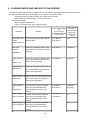
4. FAQ (Problems Specific to the iP5200 and Corrective Actions)
No. *
1
B
Function
Print
results
Phenomenon
Condition
Cause
Skewed paper - Paper feeding
feeding
from the
cassette, Photo
Paper Plus
Double Sided, 5
x 7 size
Due to its
mechanism,
contact of the PF
pinch rollers to
the 5 x 7 size
paper is uneven,
which is likely to
cause skewed
paper feeding.
Corrective action
Change the
paper feeding
method from the
cassette to the
auto sheet
feeder.
Possible call
or complaint
- Paper feeds
at an angle.
- A margin
appears on
printouts.
Improper paper - Paper feeding
feeding:
from the ASF
- Multi-feeding - Plain paper
- Highest print
- Skewed
paper feeding speed (Custom
setting to 5)
- Paper jam
- In the high
temperature and
high humidity
environment
2
B
Paper
feed
In the high
- Reduce the
- Multiple
temperature and
amount of
sheets of
high humidity
paper set in the
paper feed
environment,
ASF to half
at the same
paper becomes
(approx. 5 mm
time.
wavy; in the low
high).
- Paper feeds
temperature and
at an angle.
low humidity
- A paper jam
environment,
occurs.
paper curls
significantly.
When the
- In the low
temperature and maximum
amount of paper
low humidity
is set in the ASF,
environment
and if the paper- With the
return tab fits in a
maximum
wave or curl of
amount of paper the paper, the tab
set (13 mm)
slips and does
not catch paper
properly, causing
paper feed
problems.
Skewed paper - Paper feeding
feeding (at the
from the ASF
level of +/- 1%) - Credit Card size
3
C
Print
results
2-7
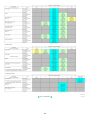
Since coaxial
- Align the paper
tolerance
guide to the
between the
paper edge
pinch roller and
tighter than
the LF roller,
usual.
which determines
the paper feed
alignment, is
0.2mm, skewed
paper feeding
can occur.
However,
according to the
field data of
current models,
the skewness
level caused by
the coaxial
tolerance of
0.2mm is within
the criteria of +/1%, thus the
phenomenon is
left as is.
- Paper feeds
at an angle.
- A margin
appears on
printouts.
4
5
A
B
Print
results
Soiling on the - After continuous
back side of
borderless
paper (lines or
printing of small
streaks parallel sized paper
to the paper
(such as 4 x 6),
feed direction)
when a larger
sized paper
(such as A4) is
printed.
- With Photo
Paper Plus
Double Sided or
postcards, the
phenomenon is
likely to be
noticeable and to
be complained of
by users, as
printing is
performed on
both sides of
such paper.
In borderless
1. Perform
- Paper gets
printing, printing
Bottom plate
smeared.
is performed to
cleaning (from - The back
the size slightly
the printer
side of
larger than the
driver) up to 3 paper gets
paper size, and
times*1.
smeared.
ink off the paper
2. If soiling on
is absorbed by
the paper still
the platen's ink
remains after
absorber.
3 times of
Absorbed ink
Bottom plate
may attach to the
cleaning, wipe
platen rib(s) after
the platen rib
several dozen
(s) and their
sheets are
surroundings
printed, causing
with a cotton
soiling at the
swab.
leading edge of
paper or on the
back side of
paper.
Soiling on
- Automatic duplex
paper in
printing (Photo
automatic
Paper Plus
duplex printing
Double Sided,
(lines or
postcards, plain
streaks
paper)
perpendicular
to the paper
feed direction)
On the rib(s)
inside the sheet
feed unit used for
duplex printing,
ink mist may
accumulate,
smearing paper.
Print
results
- Paper gets
Temporary
smeared.
operational
solution:
- The back
Cancel automatic side of
duplex printing,
paper gets
and manually
smeared.
print each side of - Even after
paper.
Bottom plate
cleaning
Cleaning by
was
user:
performed,
and the
1. Perform
platen ribs
Bottom plate
cleaning (from were
cleaned with
the printer
driver) up to 3 cotton swab,
paper gets
times*1.
smeared.
2. If soiling on
the paper still
remains after
3 times of
Bottom plate
cleaning, wipe
the platen rib
(s) and their
surroundings
with a cotton
swab.
If the
phenomenon
persists after
conducting 1 and
2, servicing is
required.
Service:
Wipe any soiling
or dirt off from the
sheet feed unit
2-8
and the bottom
case unit ribs*2.
Scratches on
paper
6
C
- PP-101D, PP101, PR-101,
SG-101, etc.
- Paper feeding
from the
cassette
Scratches on the - Change the
PF return lever
paper feeding
due to paper
method from
feeding from the
the cassette to
cassette, and
the auto sheet
duplex printing
feeder.
path.
- If automatic
duplex printing
is performed,
cancel it, and,
by setting only
a single sheet
of paper in the
auto sheet
feeder,
manually print
each side of
paper.
- PP-101D, PP101, PR-101,
SG-101, etc.
Set only a single
sheet of paper in
the auto sheet
feeder.
Print
results
When multiple
sheets of paper
are set, the back
side of paper
- Paper feeding
being picked up
from the ASF
scratches the
- Multiple number front side of
of sheets loaded paper beneath
(especially where
the paper feed
rollers contact
when picking up
the paper).
Soiling on
paper
7
C
The printer has
been used for a
long period of time
with the ASF
cover closed
before printing is
performed using
the ASF.
Print
results
Skewed paper - SG-101
feeding
- Paper feeding
from the ASF
Due to ink mist
Clean the ASF
attached to the
sub-rollers (see
ASF sub-pick-up *3 for details.)
rollers.
If printing is done
from the cassette
with the ASF
cover closed, ink
mist is kept
inside the printer,
attaching to the
ASF sub-pick-up
rollers.
Since the subrollers usually do
not contact the
paper, ink mist
can easily
accumulate,
especially during
printing on smallsized paper
which never
contacts the subrollers.
When 10 sheets - Straighten the
of paper are set
paper.
in the ASF, and if - Set 5 or less
2-9
- Paper is
scratched.
- Marks
appear on
printed
paper.
- Paper feeds
at an angle.
- A margin
8
9
B
B
sheets of paper
- 10 sheets (max.) they warp
significantly,
the
in the ASF.
set in the ASF
warping portions
of paper get over
the cover guide,
not being aligned
along the guide
properly.
Print
results
Print
results
Uneven
- In the low
printing at the
temperature and
trailing edge of
low humidity
paper
environment
Due to decrease - Perform Bottom
of the friction
plate cleaning.
coefficient of the
paper ejection
- Perform manual
rollers, or due to
print
head
inaccuracy of the
alignment.
print head
alignment
appears on
printouts.
Uneven
printing at the
bottom of
paper
*1: Change the paper in each Bottom plate cleaning. The cleaning can end when paper does not get any
soiling.
*2: Locations to clean in servicing when soiling on paper in automatic duplex printing persists:
*3: How to prepare and set the ASF sub-roller cleaning sheet:
1) Fold a sheet of plain paper lengthwise in half.
2) Fold the paper at approx. 60 mm from the end, and fold the folded end in half backward, as shown
below.
2-10
3) Moisten the folded end portion (indicated by the blue circle in the figure below) using a wipe, and
set the paper in the ASF so that the moistened edge of the paper contacts the 2 sub-rollers. Then,
fold the other end of the paper along the ASF cover edge to hook the paper to the ASF cover, as
shown below.
4) Press and hold the Resume/Cancel button until the Power LED blinks 3 times, then release the
button to perform the paper feed roller cleaning. See "Stand alone printer operation," for details.
* Occurrence level:
A: The symptom is likely to occur frequently. (Caution required)
B: The symptom may occur under certain conditions, but likeliness is assumed very low in practical
2-11
usage.
C: The symptom is unlikely to be recognized by the user, and no practical issues are assumed.
To the top
<Part 2: 4. FAQ>
2-12
Part 3
APPENDIX
PIXMA iP5200 Specifications
<Printer>
Type
Desktop serial color bubble jet printer
Paper feeding method Auto sheet feed (ASF, cassette, automatic duplex printing, CD / DVD printing*1)
Resolution
9,600 x 2,400dpi (Max.)
Throughput (target
value)
- 4 x 6, borderless printing: Approx. 36 sec. (standard mode, PP-101, Full Page
SCID No. 2)
- Camera Direct Printing: Approx. 1 minute and 19 sec. (4 x 6, borderless printing,
PP-101, default settings)
For reference:
Fast
Standard
Black (Fine Black)
30ppm
15.0ppm
Color (Fine Color)
24ppm
11.7ppm
Printing direction
Bi-directional, uni-directional
Print width
Max. 203.2mm (216mm in borderless printing)
Interface
USB 2.0 Hi-Speed
ASF stacking capacity Plain paper: Max. 13mm (Approx. 150 sheets of 64g/m2 paper)
Paper weight
64 to 105g/m2
Detection functions
Access cover open, Presence of print head / ink tanks, Opening / Closing of front
door, Remaining ink amount (optical / dot count), Printing position, Paper presence,
Paper end sensor, Waste ink amount, Internal temperature, Pick-up roller, Paper
feed roller position, Carriage position, Head-to-paper distance, Supported camera
direct printing device, Presence of CD / DVD
Acoustic noise
(Highest print quality)
- Highest print quality settings: Approx. 34.7dB
- Quiet mode: Approx. 34.3dB
During operation
Environmental
requirements
Temperature
Humidity
Non operation
Temperature
Humidity
Power
consumption
Approx. 17W
Approx. 17W
5C to 35C (41F to 95F)
10%RH to 90%RH (no
condensation)
0C to 40C (32F to 104F)
5%RH to 95%RH (no condensation)
Power supply
Power supply voltage,
frequency
AC 100 to 120V, 50/60Hz
AC 220 to 240V, 50/60Hz
External dimensions
Printer:
With the paper support and output tray retracted:
Approx. 444 (W) x 309 (D) x 160 (H )mm
Approx. 17.7 (W) x 12.3 (D) x 6.4 (H) inches
Weight
Approx. 7.3kg, not including print head and optional units
Related standards
(Printer, Adapter)
Electromagnetic radiance:
FCC, IC, CE Mark, Taiwan EMC, C-tick, CCC (Chinese EMC), Korea MIC, GostR
Electrical safety:
UL, C-UL, CB Report, CE Mark, GS, Gost-R, FT, SASO, CCC(Safety), SPRING,
Korea EK, IRAM (Argentine Safety)
Standby
Power-off
Approx. 0.8W
Approx. 0.8W
Approx. 0.4W
Approx. 0.4W
Environmental regulations:
RoHS (EU), WEEE (EU), Korea Package Recycle Law, Green Point (Germany),
Energy Star
Serial number location On the carriage flexible cable holder (visible on the right of the carriage after the
printer is turned on, the access cover is opened, and the carriage moves to the
3-9
center.)
Remaining ink amount
Available (automatic detection by optical method and dot count, enabled at default)
detection
Paper type detection
Not available
Print head alignment
Available (automatic or manual alignment via driver utilities, or the Resume/Cancel
button in Camera Direct Printing, automatic alignment at default)
*1: Only for CD / DVD printing supported regions
<Print head>
Type
Single head with 5 removable ink tanks (each color)
Print head
Black: 512 nozzles (600dpi), 30pl (pigment-based black)
Color: 512 nozzles x 6 (1,200dpi), 1pl / 5pl (cyan, magenta), 5pl (black, yellow)
Ink color
Pigment-based black, Dye-based black, cyan, magenta, yellow
Ink tank
PGI-5BK (pigment-based), CLI-8BK/C/M/Y (dye-based)
Weight (Net)
Print head, approx. 60g
Supply method
As a service part (not including ink tanks)
Part number
QY6-0061-000
<Supported ink tanks>
Model
PIXMA iP5200
Destination
Overseas
models
Pigmentbased
Dye-based
PIG-5BK
CLI-8BK
CLI-8C
CLI-8M
CLI-8Y
O
O
O
O
O
BCI-9BK
BCI-7eBK
BCI-7eC
BCI-7eM
BCI-7eY
X
X
X
X
X
O: Usable X: Not usable
Note:
The ink tanks BCI-9BK and BCI-7e series available in Japanese market are not compatible with the
PIXMA iP5200 overseas models.
Be sure to use the appropriate ink tanks in servicing.
To the top
<PIXMA iP5200 Specifications>
3-10
PIXMA iP5200R
REFERENCE MANUAL
This reference manual describes differences from the base model, PIXMA iP5200.
When referring to the PIXMA iP5200 Service Manual, Service Parts Number in it may be different
from PIXMA iP5200 model. Please refer to the PIXUS iP5200R/PIXMA iP5200R Parts Catalog
(QY8-9083-D0C).
QY8-13AJ-000
1
TABLE OF CONTENTS
Page
3
3
Part 1:
3
3
2.
3
3
3
4
5
1.
3.
Part 3:
8
8
1.
2.
MAINTENANCE
MAINTENANCE
1.1 Adjustment, Periodic Maintenance, Periodic Replacement Parts, and
Replacement Consumables by Service Engineer
LIST OF ERROR DISPLAY / LIST OF TROUBLESHOOTING
2.2 Service Call Errors (by LED Blinking in Orange and Green Alternately, or Lit in
Orange)
2.4 Troubleshooting by Symptom
REPAIR
3.1 Notes on Service Part Replacement
3.2 Special Notes on Repair Servicing
3.4 Verification Items
(3) Network setting information (NIC EEPROM information) Print
APPENDIX
BLOCK DIAGRAM
PIXMA iP5200R SPECIFICATION
2
Part 1
1.
MAINTENANCE
MAINTENANCE
1.1
(1)
Adjustment, Periodic Maintenance, Periodic Replacement Parts, and
Replacement Consumables by Service Engineer
Adjustment (added to iP 5200)
Adjustment
Timing
Network setting
information print
(NIC EEPROM
information print)
2.
NIC BOARD
replacement
To confirm operations
Tool
None.
Approx.
time
1 min.
LIST OF ERROR DISPLAY / INDICATION
2.2
Service Call Errors (added to iP5200)
Cyclic blinking in
orange (Alarm
LED) and green
(Power LED)
18 times
2.4
Faulty operation
3.
Purpose
Solution
(Replacement of listed parts, which are likely to be faulty)
Error
NIC BOARD error
[6550]
NIC BOARD ASS’Y (QK1-1973-000)
Troubleshooting by Symptom
Symptom
Printing is not possible with
wireless LAN.
Solution
1) Perform network setting information
print.
When printing is not possible. -> Replace
the NIC BOARD.
When printing is possible. -> Proceed to
2).
2) Perform printing with the wireless
LAN I/F.
When printing is not possible. -> Replace
the NIC BOARD.
(Wireless reception component failure on
the NIC BOARD)
When printing is possible. -> Re-confirm
network setting (user’s environment).
Remarks
REPAIR
3.1
Notes on Service Part Replacement (and Disassembling/Reassembling)
Service part
Notes on replacement
NIC BOARD ASS’Y
(QK1-1973-000)
Adjustment/settings
Operation check
- Network setting
information print
- Printing with
wireless LAN I/F
(After printing,
EEPROM
initialization of NIC
BOARD is
necessary.)
3
Note:
If the NIC BOARD is replaced, user network setting information stored in the NIC BOARD
is lost. Therefore, it is necessary to inform users that network setting should be performed
again to enable the printer to be used under the user’s environment.
<How to re-perform network setting>
a.
Performing Easy Install
Application software, User’s Guide, etc, are also re-installed.
b.
Custom Install
The following items are selected as installation.
- Printer driver
- Network Setup
- Canon IJ Network Tool
3.2
Special Notes on Repair Servicing
(4)
User mode (added to iP5200)
Function
Network setting information print
(NIC EEPROM information
printing)
Initialization of network setting
information
Procedures
See <Standalone printer operation> below.
See <Standalone printer operation> below.
Remarks
Can also be
performed from
Canon IJ Network
Tool
<Standalone printer operation>
1) Turn on the printer and the Reset button.
2) After the Power LED (green) blinks the specified number of times listed in the table below, release it.
The operation starts.
LED blinking
Operation
Remarks
6 times
Network setting information printing
Set a sheet of A4/LTR-sized plain paper in the
sheet feeder or cassette. (The Paper Feed
switch controls the paper feeding location.)
10 times
Initialization of network setting
information
10 times or more Unspecified
For details on the network setting information printing and items cleared by initialization, see “3.4.
Verification Items (3) Network setting information (NIC EEPROM information) print”.
< WPA2 setting >
When setting WPA2 as an encryption method, be aware that there is a restriction as follows.
- When setting WPA2 from Network Tool, since WPA2 setting by entering SSID manually from the
Configuration screen is impossible, perform WPA2 setting after selecting an access point by pressing the
Search button .
WPA2 setting is also possible by re-installing the driver and from Network Configuration of a Web
browser.
4
3.4
(3)
Verification Items
Network setting information (NIC EEPROM information) print
<EEPROM information sample>
Canon iP5200R Network Congiguration Page
Printer
Firmware Version
: iP5200R
:1.02
Wireless LAN
Standard
Destination
MAC Address
: Enabled
: IEEE 802.11g
: 1B
: xx-xx-xx-xx-xx-xx
Network Type
: Infrastructure
SSID
: xxxxx
Channel
: 10
Encription
: OFF
Authentication
: Open System
Attached Information:
Link Status
Signal Strength
Link Quality
Transmission Rate
: Active
: 63%
: 56%
: 36Mbps
TCP/IP
Mode
IP Address
Subnet Mask
Default Gateway
: Auto
: xxx.xxx.x.xxx
: xxx.xxx.xxx.x
: x.x.x.x
Wired LAN
MAC Address
Link Status
Transmission Rate
: Disable
: xx-xx-xx-xx-xx-xx
: Inactive
:
TCP/IP
Mode
IP Address
Subnet Mask
Default Gateway
:
:
:
:
Printer Access Control
MAC Address
: OFF
IP Address
: OFF
Admin Password
Device Status
: OFF
: Available
5
<EEPROM information contents>
Print items:
List item for network setting print
Contents:
Meaning of list items
Settable values:
Settable values for users
Default values:
Values at shipment from the plant
Items set to default values: Items re-set to the factory values (at shipment) by initialization
Print items
Printer
Firmware
Version
Wireless LAN
Standard
Destination
MAC Address
Contents
Settable values
Default values
* Items
set to
default
values
Printer name
NIC firmware version
-
IP_5200R (Overseas)
[Specific value. fixed]
Wireless LAN enabled/disabled
Compliant wireless LAN standard
Corresponding channel list
MAC address for wireless LAN on
NIC board
Operation mode of wireless LAN
Enabled/Disabled
-
Enabled
IEEE 802.11g[fixed]
1B [fixed]
[NIC BOARD-specific
value. Fixed]
Infrastructure [fixed]
O
Optional
(can be freely set.)
BJNPSETUP
O
O
OFF
Open System
O
O
Attached
Information
Attached information regarding
encryption and authentication
[Varies depending on
connection status.]
OFF/WEP/TKIP/AES
Auto
/Open System
/Shared Key/WPA-PSK/
WPA2-PSK
WEP setting:
64/128bit, ASCII/Hex,
Key*
* Key set by user is
displayed.
WPA-PSK setting:
Character Password
/64 Hex digits
[Blank]
Encryption
Authentication
Set SSID
When ANY is set, current SSID
is printed in parentheses.
Current channel
When inactive, left blank
Current encryption method
Current authentication method
[Blank]
O
Link Status
Status of wireless LAN
When wireless LAN is invalid, if
nonexistent SSID is set, status
becomes Inactive.
Other than this case, status
becomes Active.
Signal strength: 0 - 100 %
When inactive, 0 %
Network Type
SSID
Channel
Wireless LAN setting information
Signal
Strength
Link Quality
Transmission
Rate
TCP/IP(wireless)
Mode
IP Address
Subnet Mask
Default
Gateway
Communication quality: 0 100 %
When inactive, 0 %
Current wireless LAN speed:
1/2/5.5/6/9/11/12/18/24/36/48
/56 Mbps
When inactive, left blank
IP address setting method
When disabled, left blank
Current IP address
When disabled, left blank
Current Subnet mask
When disabled, left blank
Current default Gateway
When disabled, left blank
-
Inactive
-
[Varies depending on
communication
environment.]
[Varies depending on
communication
environment.]
[Varies depending on the
communicating devices.]
0%
Auto/Manual
Auto
O
0.0.0.0 255.255.255.255
0.0.0.0 255.255.255.255
0.0.0.0 255.255.255.255
192.168.1.123
O
255.255.255.0
O
0.0.0.0
O
6
0%
[Blank]
Wired LAN setting informaton
Wired LAN
MAC Address
TCP/IP (wired)
Mode
Security
Other
Wired LAN enabled/disabled
MAC address for wired LAN
on NIC board
Status of wired LAN
When wired LAN is invalid,
status becomes Inactive.
Other than this case, status
becomes Active.
Current wireless LAN speed
10/100 Mbps
When inactive, left blank
Enabled/Disabled
-
Auto/Manual
Auto
O
0.0.0.0 - 255.255.255.255
192.168.2.123
O
0.0.0.0 - 255.255.255.255
255.255.255.0
O
Default
Gateway
MAC Address
IP address setting method
When disabled, left blank
Current IP address
When disabled, left blank
Current Subnet mask
When disabled, left blank
Current default Gateway
When disabled, left blank
MAC address filtering setting
0.0.0.0 - 255.255.255.255
0.0.0.0
O
ON/OFF
OFF
O
IP Address
IP address filtering setting
ON/OFF
OFF
O
Admin
Password
Device Status
Admin password setting
ON/OFF
OFF
O
Available
O
Link Status
Transmission
Rate
IP Address
Subnet Mask
-
Enable
[NIC BOARD-specific
value. Fixed]
Inactive
[Blank]
-
Printing of device status
When error occurs, error
code is displayed. Other
than this case, Available is
displayed.
7
Part 3
1.
APPENDIX
BLOCK DIAGRAM
Logic Board
NIC board
Sub I/F board
CN1
CN304
ASIC
Ethernet I/F
CN2
Wired LAN
controller
ROM
RAM
Wireless LAN
I/F
Wireless
LAN
controller
CN302
USB I/F
The parts other than NIC Board
and /F board are same as iP5200.
2. PIXMA iP5200R SPECIFICATION (differences from iP5200)
< Specifications >
Wireless LAN, wired LAN interface port (RJ-45) x1
USB 2.0 Hi-Speed x1
Interface
Printing speed*
(Wireless printing)
Color (4x6)
PP-101 / Standard /
Borderless
Power consumption
Weight
Related standards (Proposed)
(Printer, Adapter)
56 sec.
Standby: 3 W
Off:
0.4 W
During printing: Approx. 19 W
7.5 Kg
Electromagnetic radiance:
VCCI, FCC, IC, CE Mark, C-Tick
Electrical safety:
Electrical Appliance and Material Safety Law (DENAN),
UL, C-UL, CB Report, CE Mark, GS, FT, SPRING
Wireless:
FCC, IC, CE Mark (R&TTE), ACA, RSM,
Telecommunication Act (SPL)
Environmental regulations:
RoHS (EU), WEEE (EU), Energy Star, Eco Mark, Law on
Promoting Green Purchasing, Chemical Substances
Control Law, Battery Recycle Law, Container and
Packaging Law, Blue Angel
* Text printing speed and printing speed when connected with the USB cable are the same as the PIXMA iP5200.
* Printing speed when connected with wireless LAN varies depending on communication speed and environmental
conditions.
8
< Network specifications >
Communication protocol
Wired LAN
Compliant standard
Transmission speed
Wireless LAN
Compliant standard
Used frequency band
Channel
Transmission system
Transmission speed
Communication distance
Security
Other
Acquired standard
TCP / IP, UPD
IEEE802.3u (100BASE-TX) / IEEE802.3 (10BASE-T)
10M / 100Mbps (automatic switching)
IEEE802.11g / IEEE802.11b, ARIB STD-T66
2.412GHz-2. 462GHz
1-11
OFDM / DS-SS system
54 / 48 / 36 / 24 / 18 / 12 / 9 / 6Mbps (IEEE802.11g, automatic changing)
11 / 5.5 / 2/ 1Mbps (IEEE802.11b, automatic switching)
50 m *varies depending on communication speed and environmental
conditions
WEP (64/128 bit), WPA-PSK (TKIP/AES), WPA2-PSK (TKIP/AES)
Wi-Fi logo acquired
TELEC, FCC, IC, ETSI, iDA
9