1
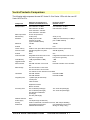
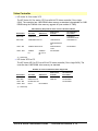
HP Vectra VL 5/xx and VE 5/xx Familiarization
Guide
Printed Manual Information
Trademarks
Overview and Features
Introduction
Vectra Products Comparison
Product Features
Microprocessor
Cache Memory
DRAM Main Memory Modules
System ROM
SETUP Program
Video Controller
Preinstalled Software
Disk Controllers
Front Accessible Mass Storage Shelves
Internal Mass Storage Shelves
Supported Drives
Control Panel
Security Features
Communications Ports
Supported Operating Systems
Documentation
PC Hardware Structure
Introduction
Packaging
Installing Accessories
Installing Main Memory
Installing Video Memory
Installing Cache Memory
Installing an Accessory Board
Replacing the Microprocessor
System Board Jumpers
System Board Switches
Troubleshooting and Repair
Overview
Warranty
Field Replaceable Parts
Using SETUP to Configure the PC
Power-on System Hardware Tests
Updating the System ROM
Diagnostic Utility
VL5/xx & VE5/xx Familiarization Guide
Overview and Features • 1
VL5/xx & VE5/xx Familiarization Guide
Overview and Features • 2
Printed Manual Information
Hewlett-Packard Company
© 1995
VL5/xx & VE5/xx Familiarization Guide
Overview and Features • 3
Trademarks
Centronics® is a registered trademark of Centronics Data
Computer Corporation.
Microsoft® and MS-DOS® are U.S. registered trademarks of
Microsoft Corporation. LANManager, Microsoft Windows,
Windows 95 and OS/2 are products of Microsoft Corporation.
Novell® and NetWare® are U.S. registered trademarks
of Novell, Inc.
OS/2™ is a product of International Business Machines.
PENTIUM™ is a trademark of Intel Corporation.
UNIX™ is a registered trademark of UNIX System Laboratories
Inc. in the U.S.A. and other countries.
Windows™ is a trademark of Microsoft Corporation.
VL5/xx & VE5/xx Familiarization Guide
Overview and Features • 4
Overview and Features
VL5/xx & VE5/xx Familiarization Guide
Overview and Features • 5
Introduction
This guide is for experienced HP Response Center personnel, CEs, and reseller technicians.
That is, personnel who have already completed the HP Vectra PC family training course, or
equivalent, and have at least six months of experience servicing the HP Vectra PCs.
It is a self-paced training guide designed to train you to install, configure, and repair the PC.
You can follow it without having any equipment available.
After reading this chapter, you will be able to describe the features specific to these PCs.
VL5/xx & VE5/xx Familiarization Guide
Overview and Features • 6
Vectra Products Comparison
The following table compares the new HP Vectra VL 5/xx Series 3 PCs with the new HP
Vectra VE 5/xx PCs.
Component
Microprocessor
Math coprocessor
Main Memory
Standard
Maximum
Sockets
Cache memory
2nd level cache
Sockets
Video Controller
Video Memory
Upgrade Socket
Disk Controller
Mass storage
Hard Disks
Integrated ports
HP Vectra VL 5/xx Series 3
(D339xA and D340xA series)
HP Vectra VE 5/xx
(D339xA series)
5/75: Pentium™ 75 MHz
5/75: Pentium™ 75 MHz
5/90: Pentium™ 90 MHz
5/90: Pentium™ 90 MHz
5/100: Pentium™ 100 MHz
5/120: Pentium™ 120 MHz*
On the microprocessor
32-bit (70 ns)
32-bit (70 ns)
4 MB (one 4 MB module) or 8 MB (a
8 MB (a pair of 4 MB
pair of 4 MB modules)
modules) or 16 MB
(a pair of 8 MB modules)
128 MB
192 MB
Four
Six
8 KB for code, plus 8 KB for data (both caches on the microprocessor)
256 KB (Integrated on system
256 KB (Optional)
board)
None
One
Integrated 64-bit Ultra VGA on PCI
Integrated 32-bit Ultra VGA on PCI
bus (Cirrus Logic 5434)
bus (Cirrus Logic 5430)
1 MB (expandable to 2 MB)
1 MB
One
None
Fast IDE controller on PCI local
Fast IDE controller on PCI local bus
bus
One front access 3.5-inch shelf
One front access 5.25-inch shelf
Two internal 3.5-inch shelves for hard disks
Fast IDE 420 MB
Fast IDE 270 MB
Fast IDE 840 MB
Fast IDE 540 MB
1 parallel port (bi-directional)
2 serial ports
VGA connector
Keyboard connector
Accessory slots
Mouse connector
One 16-bit ISA (full-length)
One 16-bit ISA (half-length)
Two 16-bit ISA (full-length)
Two 16-bit ISA (half-length)
One PCI/ISA Combination
(full-length)
One PCI (half-length)
Network Interface
Power supply
Security
None
100 W (full range 90-264 VAC)
Power-on Password, mechanical cover lock, disk and port disabling.
Passwords
User Password and System
Administrator Password
VL5/xx & VE5/xx Familiarization Guide
User Password (may be set to
Always or Setup Only)
Overview and Features • 7
Preinstalled
software
BIOS ROM
System ROM
localization
MS-DOS 6.22, Windows for Workgroups 3.11, Dashboard, HP User Tool,
Drivers
HP BIOS, Flash EEPROM
English Only
*Future models.
VL5/xx & VE5/xx Familiarization Guide
Overview and Features • 8
Product Features
Overview
The HP Vectra VL 5/xx Series 3 and HP Vectra VE 5/xx PCs are PENTIUM processor,
ISA/PCI-based PCs. The whole platform consists of a system board and a backplane.
• The VL backplane has two ISA slots, one PCI slot, and one combination ISA/PCI slot for
accessory boards.
• The VE backplane has four ISA slots for accessory boards.
The I/O connectors are located on the system board. The same mid-profile package is used
as in the Vectra VL2 series PCs.
The main features of the system board are:
• A 64-bit host bus for PENTIUM processor and main memory (DRAM).
• A 32-bit Peripheral Component Interconnection (PCI) local bus for accessing the
processor, video controller, and controller components.
• An industry-standard architecture (ISA) bus for ISA-compatible controllers.
• A security system that provides protection against unauthorized use of the PC.
• A flash BIOS updating facility.
VL5/xx & VE5/xx Familiarization Guide
Overview and Features • 9
Microprocessor
The Pentium microprocessors used in the HP Vectra VL 5/xx series 3 and HP Vectra VE
5/xx are the latest generation of the Intel family of microprocessors. These microprocessors
use internal clock multiplication, similar to that used by the 486 DX2 processor. The
microprocessor’s internal clock is a multiple of the system clock. The Pentium 75, 90, and
100 MHz processor multiply the 50, 60, and 66 MHz system clock by a factor of 1.5. The
Pentium 120 MHz processor doubles the 60 MHz system clock.
These new Pentium processors are powered by a power source of 3.3 V (see Configuring
the Processor Voltage Selection Jumper). The previous generation of Pentium processors,
Pentium 60 MHz and 66 MHz, used a 5 V power source. The two generations of processors
are not pin compatible.
VL5/xx & VE5/xx Familiarization Guide
Overview and Features • 10
Cache Memory
The microprocessor has two 8 KB first-level caches: one for the instruction codes and the
other for data.
• The HP Vectra VL 5/xx series 3 PC has 256 KB of second-level cache memory, which is
soldered onto the system board.
• The HP Vectra VE 5/xx has a socket for a 256 KB second-level cache memory module.
When the optional second level cache is not installed in the VE, the cache socket protector
must be installed in the empty cache. The role of the cache socket protector is to properly
terminate the Pentium host bus.
VL5/xx & VE5/xx Familiarization Guide
Overview and Features • 11
DRAM Main Memory Modules
• The HP Vectra VL 5/xx series 3 PC has six sockets on the system board. 8 MB or 16
MB of memory is supplied as standard, expandable to 192 MB.
• The HP Vectra VE 5/xx has four sockets on the system board. 4 MB or 8 MB of memory
is supplied as standard, expandable to 128 MB.
Each pair of sockets forms a bank. When two memory modules are installed within the same
bank, they must be of the same size.
The PCs use 70 ns, 32-bit wide, memory modules. When additional memory modules are
installed, the following rules must be applied to get the best performance:
1. Install two identical-size SIMMs in the same bank to enable 64-bit wide access to this
bank.
2. Install four identical-size SIMMS in bank A and B to enable memory interleaving
between the two banks.
The memory upgrades available are:
• 4 MB, 32-bit, 70 ns (D2690A) or 4 MB, 36-bit, 70 ns (D2974A)
• 8 MB, 32-bit, 70 ns (D2691A) or 8 MB, 36-bit, 70 ns (D2975A)
• 16 MB, 36-bit, 70 ns (D2297A)
• 32 MB, 36-bit, 70 ns (D2298A)
When 36-bit SIMMs are installed, it is possible to enable parity checking by enabling the
parity switch (PARIT) on the system board.
VL5/xx & VE5/xx Familiarization Guide
Overview and Features • 12
System ROM
The PCs have a system ROM that uses flash EEPROM technology. The flash ROM can be
updated with the latest firmware using the HPROMinit program (HPINIT.EXE) supplied with
the firmware upgrade. While updating the flash ROM, the power switch is disabled to
prevent interruption of the flash programming process. A switch on the system board
prevents unauthorized flash programming.
The system ROM contains:
• The HP BIOS
• A power-on system hardware test, which provides an error message utility that displays
error diagnosis and corrective actions
•
a SETUP program with context-sensitive help (in English only).
When the PC is started, the Power-On Self Test (POST) screen is displayed:
If the POST detects an error:
• Press [ENTER] to display a message describing the error and how to fix it
• Press [F2] to start SETUP to check the configuration
• Alternatively, press [F1] to continue.
VL5/xx & VE5/xx Familiarization Guide
Overview and Features • 13
SETUP Program
The HP Vectra VL 5/xx series 3 PC and the HP Vectra VE 5/xx PC have an integrated
SETUP program (like the HP Vectra VL2 and XP PC series, but in English only).
SETUP is started by pressing when the message <Setup=F2 > appears.
VL5/xx & VE5/xx Familiarization Guide
Overview and Features • 14
Video Controller
• HP Vectra VL 5/xx series 3 PC
The HP Vectra VL 5/xx series 3 PC has a 64-bit PCI video controller (Cirrus Logic
5434). The controller has 1 MB DRAM video memory as standard, upgradeable to 2 MB
DRAM using the D3404A video memory upgrade kit (one module of 1 MB).
Video Memory Required for these Colors and Refresh Rates
Resolution
16 Colors
256 Colors
640 X 480
1 MB 60/72/75 Hz
800 X 600
1 MB 56/60/72/75 Hz
1024 x 768
1 MB 87i*/60/70/75 Hz
1280 x 1024
1 MB 87i
Hz
2 MB 87i/
60/ 72/ 75
Hz
64 K Colors
Hi-Color
1 MB 56/60 Hz
2 MB 56/60/72/75
Hz
2 MB 87i/60/70/
75 Hz
Not Available
16.7 M Colors
True-Color
1 MB 60 Hz
2 MB 60/72/75 Hz
2 MB 56/60 Hz
Not Available
*(i = Interlaced)
• HP Vectra VE 5/xx PC
The HP Vectra VE 5/xx PC has a 32-bit PCI video controller (Cirrus Logic 5430). The
controller has 1 MB DRAM video memory as standard.
Number of Colors and Refresh Rates Supported
Resolution
16 Colors
256 Colors
640 x 480
800 x 600
1024 x 768
1280 x 1024
60/72/75 Hz
56/60/72/75 Hz
87i*/60/70/75 Hz
87i Hz
Not Available
64 K Colors
Hi-Color
16.7 M Colors
True-Color
56/60 Hz
60 Hz
Not Available
Not Available
*(i = Interlaced)
VL5/xx & VE5/xx Familiarization Guide
Overview and Features • 15
Preinstalled Software
Models with hard disk drives are supplied with preinstalled software:
Utilities and Drivers
Software
• HP User Tools
• MS-DOS 6.22
• Mouse Control Center
• MS-Windows for Workgroups 3.11
• Video Drivers
• Dashboard
• Disk Drivers (32-bit disk access)
• Plug and Play (ICU)
• Advanced Power Management
• Desktop Management Interface
The first time the PC is powered on, a software initialization program runs to allow the user
to set up the preinstalled software for the display type and the printer.
On models without a hard disk drive, the utilities and drivers are supplied on diskettes.
VL5/xx & VE5/xx Familiarization Guide
Overview and Features • 16
Disk Controllers
• HP Vectra VL 5/xx series 3 PC
The integrated flexible disk controller supports two flexible disk drives. The integrated
Enhanced IDE hard disk controller is on the PCI bus and dedicated for hard disk drives.
This is the grey connector on the system board. The cable has two connectors, allowing
two Fast IDE hard disks to be connected.
The second IDE controller is on the ISA bus and is dedicated to CD-ROM drives. This is the
red connector on the system board. The cable has one connector allowing one CD-ROM to
be connected.
• HP Vectra VE 5/xx PC
The integrated flexible disk controller supports two flexible disk drives. The integrated
Enhanced IDE hard disk controller is on the PCI bus and dedicated for hard disk drives.
This is the grey connector on the system board. The cable has two connectors, allowing
two Fast IDE hard disks to be connected.
VL5/xx & VE5/xx Familiarization Guide
Overview and Features • 17
Front Accessible Mass Storage Shelves
• Slim top shelf (1-inch high) for 3.5-inch or 5.25-inch devices.
• Half-height middle shelf for 5.25-inch devices.
VL5/xx & VE5/xx Familiarization Guide
Overview and Features • 18
Internal Mass Storage Shelves
• Two internal shelves for 3.5-inch slim (1-inch) hard disks.
VL5/xx & VE5/xx Familiarization Guide
Overview and Features • 19
Supported Drives
• 3.5-inch, 1.44 MB flexible disk drive (D2035A)
• 5.25-inch, 1.2 MB flexible disk drive (D2881A)
• 3.5-inch, 270 MB IDE hard disk drive (D2388A)
• 3.5-inch, 540 MB IDE hard disk drive (D2389A)
• Double-speed (2x) IDE CD-ROM drive (D2889A)
• Double-speed (2x) SCSI CD-ROM drive with SCSI adapter (D2886B)
VL5/xx & VE5/xx Familiarization Guide
Overview and Features • 20
Control Panel
The PCs have the same control panel as the HP Vectra VL2 PC series and have the same
features:
• A power on/off switch
• A power LED indicator (green)
• A hard disk access LED indicator.
VL5/xx & VE5/xx Familiarization Guide
Overview and Features • 21
Security Features
The PCs have the following security features:
• Power-on prompt, with user password
• Communications port protection (ports can be disabled in SETUP)
• Disk drive protection (disks can be disabled in SETUP)
• System configuration protection, using switches
• Cover lock and security bracket.
VL5/xx & VE5/xx Familiarization Guide
Overview and Features • 22
Communications Ports
The PCs have the following communications ports:
• One 25-pin parallel port (ECP/EPP bi-directional Centronics supporting IEEE 1284)
• Two 9-pin serial ports (16550-compatible)
• A power LED indicator (green)
• A hard disk access LED indicator.
VL5/xx & VE5/xx Familiarization Guide
Overview and Features • 23
Supported Operating Systems
• MS-DOS version 3.3, 4.x, 5.0, 6.0, 6.22 and above
• Microsoft Windows 95TM
• Microsoft Windows for Workgroups 3.11 and above
• Microsoft Windows 3.1 and above
• Microsoft Windows NT 3.1 and above
• OS/2 version 1.3 and above
• UNIX/386 System V from SCO version 3.2 V4.1
VL5/xx & VE5/xx Familiarization Guide
Overview and Features • 24
Documentation
Description
Part Number
HP Vectra VL 5/xx series 3 PC User’s Guide
HP Vectra VE 5/xx PC User’s Guide
HP Vectra PC Service Handbook
HP Vectra Accessory Service Handbook
HP Vectra VL 5/xx series 3 PC and HP VE 5/xx PC
Technical Reference Manual: Hardware and BIOS
HP Vectra VL 5/xx series 3 PC and HP Vectra VE
5/xx PC Familiarization Guide
D3405A kit*
D3402A kit*
5963-6103 (8th Edition)
5963-6104 (4th Edition)
on-line edition only**
D339X+49A-90001
*Specify Language Option when ordering this kit.
**This printable file can be downloaded from the HP BBS.
VL5/xx & VE5/xx Familiarization Guide
Overview and Features • 25
PC Hardware Structure
VL5/xx & VE5/xx Familiarization Guide
PC Hardware Structure • 26
Introduction
After reading this chapter, you will be familiar with the PC’s package and hardware
assembly.
VL5/xx & VE5/xx Familiarization Guide
PC Hardware Structure • 27
Packaging
The HP Vectra VL 5/xx series 3 PC and the HP Vectra VE 5/xx PC use the same mid-profile
package as the HP Vectra VL2 series.
The main external features are:
• four accessory board slots for accessories, for example, an audio board
• connectors for I/O devices on the rear panel
• four shelves for 3.5-inch or 5.25-inch devices
• control panel and name plate.
Internal Component Location
The location of the main internal components is shown below.
WARNING Care must be taken to ensure that all connectors are unplugged before
removing the system board from the PC.
VL5/xx & VE5/xx Familiarization Guide
PC Hardware Structure • 28
VL 5/xx System Board
VL5/xx & VE5/xx Familiarization Guide
PC Hardware Structure • 29
VL 5/xx Backplane
VE 5/xx System Board
VL5/xx & VE5/xx Familiarization Guide
PC Hardware Structure • 30
VE 5/xx Backplane
VL5/xx & VE5/xx Familiarization Guide
PC Hardware Structure • 31
Installing Accessories
VL5/xx & VE5/xx Familiarization Guide
PC Hardware Structure • 32
Installing Main Memory
• HP Vectra VL 5/xx series 3 PC
The HP Vectra VL 5/xx series 3 PC has six sockets on the system board, labeled A1,
A2, B1, B2, C1, and C2 in the diagram below. Each pair of memory sockets forms a
bank. Slots A1 and A2 form bank 1, slots B1 and B2 form bank 2, and slots C1 and C2
form bank 3. For the best performance, the memory modules should be installed in pairs
(modules of the same size) in the same bank. A maximum of 192 MB may be installed.
• HP Vectra VE 5/xx PC
The HP Vectra VE 5/xx PC has four sockets on the system board, labeled A1, A2, and
B1, B2 in the diagram below. Each pair of memory sockets forms a bank. Slots A1 and
A2 form bank 1, and slots B1 and B2 form bank 2. For the best performance, the
memory modules should be installed in pairs (modules of the same size) in the same
bank. A maximum of 128 MB may be installed.
VL5/xx & VE5/xx Familiarization Guide
PC Hardware Structure • 33
Installing Video Memory
HP Vectra VL 5/xx series 3 PC
The HP Vectra VL 5/xx series 3 PC is shipped with 1 MB of video memory which can be
expanded to 2 MB for resolutions of up to 1024 5 768 in 64K colors (see resolutions
supported under Video Controller in "Product Overview and Features.")
The upgrade kit (D3404A) comprises one module of 1 MB.
VL5/xx & VE5/xx Familiarization Guide
PC Hardware Structure • 34
Installing Cache Memory
HP Vectra VE 5/xx PC
The HP Vectra VE 5/xx PC has a socket for an optional 256 KB second-level cache memory
module.
The upgrade kit (D3403A) comprises one module of 256 KB.
VL5/xx & VE5/xx Familiarization Guide
PC Hardware Structure • 35
Installing an Accessory Board
HP Vectra VL 5/xx series 3 PC
The HP Vectra VL 5/xx series 3 PC has four slots that can be used for installing accessory
boards:
• the top slot can be used for a half-length PCI accessory board
• the second slot can be used for either a full-length PCI or ISA board
• the third slot can be used for a full-length 8- or 16-bit ISA board
• the fourth (bottom) slot can be used for a half-length 8- or 16-bit ISA board.
HP Vectra VE 5/xx PC
The HP Vectra VE 5/xx PC has four slots that can be used for installing accessory boards:
• the top slot can be used for a full-length 8- or 16-bit ISA board
• the second slot can be used for a full-length 8- or 16-bit ISA board
• the third slot can be used for a full-length 8- or 16-bit ISA board
• the fourth (bottom) slot can be used for a half-length 8- or 16-bit ISA board.
Accessory boards may have preferred locations and special installation instructions – refer
to the manual supplied with the board.
The PC supports Plug and Play through the ISA Configuration Utility and the Configuration
Manager driver in CONFIG.SYS.
NOTE Remember to check that the IRQ, DMA, and I/O addresses for the accessory board
are free - you may have to change the board’s settings. Always run SETUP after
installing an accessory board.
VL5/xx & VE5/xx Familiarization Guide
PC Hardware Structure • 36
Replacing the Microprocessor
The system board has a ZIF – Zero Insertion Force – “universal” socket to allow the
microprocessor to be easily changed.
Removing and Installing the Microprocessor
Move the lever and lift out the microprocessor:
Place the microprocessor in the ZIF socket with the corner marker (a dot or a broken corner)
aligned with the white dot marked on the system board and return the lever to its original
position.
Configuring the Processor Voltage Selection Jumper
Change the processor voltage selection jumper (J27) to correspond with the new processor.
Refer to the documentation supplied with the upgrade processor for more details about the
processor voltage requirement.
VL5/xx & VE5/xx Familiarization Guide
PC Hardware Structure • 37
Jumper
Function
Position VCC
Select the VCC (3.3 V) voltage for an upgrade processor
Position VR
Select the VR (3.38 V) voltage for an upgrade processor — DEFAULT
Position VRE
Select the VRE (3.52 V) voltage for an upgrade processor
NOTE If you replace a processor, make sure the jumper is set for the correct voltage.
VL5/xx & VE5/xx Familiarization Guide
PC Hardware Structure • 38
System Board Jumpers
Replacing the System Board
When replacing the system board, the bus speed jumper and processor voltage jumper
must be configured to correspond with the installed processor.
These two jumpers must be configured as follows:
HP Vectra VL 5/xx series 3 PC
Vectra Model:
VL 5/75
VL
5/90
VL
5/100
VL
5/120
Processor Voltage
Jumper Selection:
Vcc
Vr
Vre
Vre
Bus Speed
Jumper Selection:
50 MHz
60 MHz
66 MHz
60 MHz
Vectra Model:
VE 5/75
VE
5/90
Processor Voltage
Jumper Selection:
Vcc
Vr
HP Vectra VE 5/xx PC
VL5/xx & VE5/xx Familiarization Guide
PC Hardware Structure • 39
Bus Speed
Jumper Selection:
50 MHz
60 MHz
VL5/xx & VE5/xx Familiarization Guide
PC Hardware Structure • 40
System Board Switches
The PC has one system board switch block to configure the PC. Note that an HP Vectra VL
5/xx series 3 PC is shown here. The location of the system board switch block is the same
for the HP Vectra VE 5/xx PC.
Switch:
Function:
1–FLASH
Enable or prevent system ROM updates using the HPROMInit utility:
• OFF to enable system updates — DEFAULT
2–RESERVED
• ON to disable system updates.
Always OFF (not used)
3–CONFG
Retain or clear the configuration stored in EEPROM:
• OFF to retain configuration — DEFAULT
4–PSWRD
• ON to clear configuration.
Enable or clear (and disable) User and System Administrator
Passwords stored in EEPROM:
• OFF to enable passwords — DEFAULT
5–PARIT
• ON to clear passwords.
Enable or disable parity for the main memory modules:
• OFF to disable parity for the main memory modules — DEFAULT
6–PROCESSOR
• ON to enable parity for the main memory modules.
The selected speed must correspond with the speed of the installed
processor:
• OFF to select 75 MHz, 90 MHz, and 100 MHz
7–RESERVED
• ON to select 120 MHz.
Always OFF (not used)
8–RESERVED
Always OFF (not used)
VL5/xx & VE5/xx Familiarization Guide
PC Hardware Structure • 41
Troubleshooting and Repair
VL5/xx & VE5/xx Familiarization Guide
Troubleshooting and Repair • 42
Overview
After reading this chapter, you will know which subassemblies can be replaced and
understand the main features of the diagnostic diskette.
Product Identification
The rear of the computer has an identification label that shows the:
• product name, for example, HP Vectra VL 5/xx
• system (product) number, for example, D3393A
• serial number
• 5 x 5 system number, for example, D3393-60101.
This information may be required when ordering sub-assemblies for the PC.
VL5/xx & VE5/xx Familiarization Guide
Troubleshooting and Repair • 43
Warranty
The PCs are covered by a one-year on-site warranty and two years return-to-HP warranty.
Customers are responsible for owning master copies of preinstalled software.
For preinstalled software and utilities, the customer can make master diskettes or order
master diskettes of software (for ordering procedure refer to the software license certificate
included with the PC).
If the customer has a software failure, the software should be reinstalled from the master
copies.
For more details on support services and support conditions, refer to the support plan.
VL5/xx & VE5/xx Familiarization Guide
Troubleshooting and Repair • 44
Field Replaceable Parts
No.
Description
Replacement
Part Number
Exchange
Part Number
1
Box assembly
5063–4597
–
2
3
Rear Bezel Label
Key Lock Assembly
5182–1847
5062–5590
–
–
4
Logo VE 5/75
Logo VE 5/90
5042–1114
–
5042–1181
5042–1115
5042–1116
Logo VL 5/75
Logo VL 5/90
Logo VL 5/100
Logo VL 5/120
5
5042–1117
3.5–inch, h–h, Tray (5 pack) for non-supported
hard disk drives
VL5/xx & VE5/xx Familiarization Guide
5042–1183
Order product
number D2037A
Troubleshooting and Repair • 45
6
7
8
9
10
11
12
13
14
15
16
17
18
3.25–inch Hard Disk Drives
270 MB Fast IDE Hard Disk Drive (D2388A)
420 MB Fast IDE Hard Disk Drive (D2392A)
540 MB Fast IDE Hard Disk Drive (D2389A)
840 MB Fast IDE Hard Disk Drive (D2393A)
Hard Disk IDE Drive cable
Flexible Disk Drive cable
Standard IDE Drive cable
Flexible Disk Drive
Mounting Rails for 3.5–inch, non–HP Disk
Drives
Status (Control) Panel
VL 5/xx Backplane Assembly
VL 5/75 System Board (75 MHz)
VL 5/90 & 5/120 System Board (90 MHz and
120 MHz)
VL 5/100 System Board (100 MHz)
VE 5/xx System Board
VE 5/xx Backplane Assembly
Power Supply Assembly
Mouse
Main Memory Modules:
4 MB DRAM kit (D2974A)
4 MB DRAM kit – no parity (D2690A)
8 MB DRAM kit (D2975A)
8 MB DRAM kit – no parity (D2691A)
16 MB DRAM kit (D2297A)
32 MB DRAM kit (D2298A)
Pentium Processors:
Pentium 75 MHz (Vcc)
Pentium 90 MHz (Vr)
Pentium 100 MHz (Vre)
Pentium 120 MHz (Vre)
D2388–63001
D2392–63001
D2389–63001
D2393–63001
5182–1862
5182–1805
5182–1856
D2035–63004
5063–0309
5063–0889
5063–5765
D3393–63001
D3396–63001
D3399–63001
D3390–63001
5063–0887
5063–4553
C3751–60101
D2974–63001
5063–4548
D2975–63001
5063–4549
D2297–63001
D2298–63001
D2388–69001
D2392–69001
D2389–69001
D2393–69001
D3393–69001
D3396–69001
D3399–69001
D3390–69001
D2297–69001
D2298–69001
5063–7022
5063–7023
5063–7024
5063–7089
VE 5/xx Cache Socket Protector
(cache terminator module)
D3390–63002
–
VE 5/xx Cache Memory module:
256 KB Cache Memory module kit
5063–7055
–
VL 5/xx Video Memory module:
1 MB Video memory Module kit
5063–7056
–
Refer to the HP Vectra PC Service Handbook, 8th Edition, (5963-6103) for more
information.
VL5/xx & VE5/xx Familiarization Guide
Troubleshooting and Repair • 46
Using SETUP to Configure the PC
Field Name
Purpose
Options
Date
Time
User Preferences
To set date and time
YYYY/MM/DD
HH:MM:SS
Processor
Computer speed
Coprocessor
Memory Size
Memory Cache
Allows you to set:
User Password (Vectra VL)
Password (vectra VE)
Keyclick volume
Character repeat speed
Auto repeat delay
Numlock on/off at power up
Shows the type of
processor in the PC.
Shows the computer speed.
Shows the tpye of
coprocessor in the PC.
State the memory size of:
Base, on system board
Reserved
Extended
Total
Set/Not set
Set/Not set
0 to 10
2 – 30 per second
0.25 – 1 second
On/Off
Automatically
detected.
Controls level-one and
level-two memory cache.
On/Off
Enable or disable "Standby"
mode.
Enable or disable the
"Sleep At" power
management feature.
On/Off
Allows you to configure the
primary and secondary hard
disk drives.
To define if t he integrated
IDE controller is used for
the IDE hard disk drive.
None or SCSI
Custom
SCSI BIOS ROM
Address
View the SCSIBIOS ROM
address for an HP SCSI
adapter.
Enabled/None
SCSI BIOS
Shadowing
To shadow the SCSI BIOS
inf aster RAM for HP SCSI
adapters.
Enabled/Disabled
Power
Management
Standby
Sleep At
Hard Disk Drives
Drive 1
Drive 2
Interface
VL5/xx & VE5/xx Familiarization Guide
Remarks
Confirm that
SETUP has
detected and
configured the
memory size
fields. Ensure
that the TOTAL
field is correct.
For maximum
performance set
to On.
On/Off
Enabled/Disabled
Shows capacity
of the hard disk
drive if one was
detected.
Configure any
controller board
according to its
manual.
Troubleshooting and Repair • 47
Flexible Disk
Drives:
Drive 1
Drive 2
Bootable Drive
Interface
Security Features:
System
Administrator
Password (HP
Vectra VL 5/xx
only)
Start with
Keyboard Locked
Start From
Flexible Disk
Start From Hard
Disk
Flexible Disk
Drives
Hard Disk Drives
Writing on
Flexible Disks
Parallel Port
Defines the first and second
flexible disk drives.
Define which flexible disk
drive is the bootable drive.
To define if the flexible disk
drive controller is
integrated.
Keyboard locked until
Password is entered.
Integrated/
Controller board
Set/Not Set
Enabled/Disabled
Configure any
controller board
according to its
manual.
Enable when the
PC is used as a
Network Server.
Enabled/Disabled
Enabled/Disabled
Enabled/Disabled
Enabled/Disabled
Select a
combination of I/O
address and IRQ
channel.
Centronics, ECP, or
EPP.
Parallel Port
Mode
Serial Port A
Serial Port B
Select a
combination of I/O
address and IRQ
channel.
Video Primary
Adapter
Select which video adapter
mode is used by the
integrated video controller.
Video BIOS
Shadowing
Enables or disables the
copying of the video BIOS
on ISA video boards into
RAM.
Select ergonomic refresh
rates.
VGA Enhanced/
Ergonomic Modes
None, 3.5-inch 1.44
MB, or 5.25-inch
1.2 MB
Drive 1/Drive 2
VL5/xx & VE5/xx Familiarization Guide
Disable the
parallel port to
resolve an
address conflict,
prevent access to
your system, or
free an IRQ or
I/O resource.
Disable a serial
port to resolve an
address conflict,
prevent access to
your system, or
free an IRQ or
I/O resource.
EGA/VGA or
similar,
Monochrome, CGA/
Multimode 80,
CGA/ Multimode 40
Enabled/Disabled
Different refresh
rates may be
selected for
different screen
resolutions.
Troubleshooting and Repair • 48
IRQ Map for
Accessory
Boards:
IRQ 9
IRQ 10
IRQ 11
IRQ 15
View available IRQ
channels and select which
IRQs are used by installed
accessory boards.
VL5/xx & VE5/xx Familiarization Guide
HP Vectra VL:
Available for PCI/
Usedby an ISA
Board
HP Vectra VE:
Not used by an ISA
Board/Used by an
ISA Board
Troubleshooting and Repair • 49
Power-on System Hardware Tests
When the PC is switch on or reset, a power-on hardware test is performed.
VL5/xx & VE5/xx Familiarization Guide
Troubleshooting and Repair • 50
Updating the System ROM
The System ROM is updated by running the HPROMinit utility (supplied with BIOS
upgrades).
VL5/xx & VE5/xx Familiarization Guide
Troubleshooting and Repair • 51
Diagnostic Utility
The HP Vectra Diagnostic Utility is common to the HP Vectra product line. It is available
from the HP Bulletin Board System.
To use the Diagnostic Utility:
1. Insert a 1.44 MB 3.5-inch diskette in drive A, and type:
FORMAT A: /S [ENTER]
2. When the formatting has completed, type:
DEL A:\COMMAND.COM [ENTER]
3. Leave the diskette in drive A.
4. Download the ZIP file of the Diagnostic Utility to a directory on your hard disk.
5. Uncompress the ZIP file.
6. Copy all the files, except the ZIP file, to the diskette in drive A.
7. Print out the READ.ME file provided with the Diagnostic Utility files.
8. Follow the README.WRI file instructions to use the Diagnostic Utility.
The Diagnostic Utility has a menu-driven graphical interface for selecting tests for the HP
Vectra VL 5/xx series 3 and the HP Vectra VE 5/xx. The Diagnostic Utility contains:
• in-depth Power-On-Self-Tests
• tests for accessory boards
• an inspection utility to view low-level configuration informaton
• a memory module locator utility to decode memory test errors and indicate which
memory module has failed
• an error code display utility to explain error codes and indicate the probable cause of the
error.
New revisions of the Diagnostic Utility are available on the HP BBS.
VL5/xx & VE5/xx Familiarization Guide
Troubleshooting and Repair • 52