1
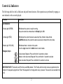
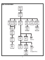
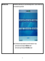
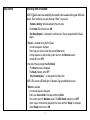
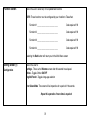
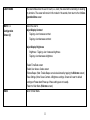
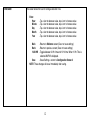
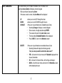
PK5590CL Touch Screen
Security Interface
Compatible with PowerSeries Control Panels
User Guide
IMPORTANT
This manual contains information on the limitations
regarding product use and function and information
on the limitations as to liability of the manufacturer.
Read the entire manual carefully.
INDEX ..............................Page
QUICK REFERENCE
Access Codes .....................13
Arming
....... Away .............................8
....... Stay...............................7
Brightness...........................11
Bypassing Zones ..................9
Chime....................................9
Clean Mode.........................11
Contrast ..............................11
Disarming...........................7,8
Emergency Buttons...............2
Functions ............................10
Language ............................10
LED Indicators ......................2
Logs ......................................9
Silence Beeps .....................11
Zones, bypassing..................9
Status Indicators ...................2
Time/Date ...........................12
Troubles (see logs)................9
Welcome screen ...................4
Welcome > Main Menu >Settings > More > Access Codes
Welcome > Main Menu > Arm Away
Welcome > Main Menu > Arm Stay
Welcome > Main Menu > Settings > More > [Brightness]
Welcome > Main Menu > Bypass
Welcome > Main Menu > Settings > More > [Chime]
Welcome > Main Menu > Settings > [Start] (Cleaning Mode)
Welcome > Main Menu > Settings > More > [Contrast]
If not visible tap screen
Welcome > Main Menu > Functions > [Function 1/2/3/4]
Welcome > Main Menu > Settings > [English]/[French]
Welcome > Main Menu > Logs
Welcome > Main Menu > Settings > More > [Silence Beeps]
Welcome > Main Menu > Bypass
Welcome > Main Menu > Settings > More > Time/Date
Welcome > Main Menu > Logs
Disarm System to view Welcome screen
1. Introduction
The PK5590CL Touch Screen is an interactive touch-sensitive color LCD that can be used on Partition 1 of any PowerSeries
control panel. Due to the custom requirements of individual installations some of the features described here may perform differently than described. Refer to your installer’s instructions for the details of your specific installation and to the User manual
for general security system information.
Specifications/Features
Display...........................................................................................................1/4 VGA (320x240 pixel) Color Touch Screen
Emergency Buttons ........................................................................................................................ 3 (Fire, Auxiliary, Panic)
LED Indicators............................................................................................................................ 3 (Ready, Armed, Trouble)
Dimensions (mounting) ....................................................................................................................................5-3/8”x3-7/8”
Wiring Distance ...................................................................................................................600ft (4-wire, 18 AWG Keybus)
NOTE: Programming changes may take up to 5 minutes to take effect. During this period the touch screen ignores user
input and displays “System Unavailable” in the Status Bar.
1
Controls & Indicators
The following table lists the Led Indicator and push button functions. Most operations are performed by tapping an
area indicated on the screen displayed.
Function
Description
LED Indicators:
Ready Light (GREEN)
ON indicates the system is ready for arming.
The system cannot be armed unless the Ready light is ON.
Armed Light (RED)
ON indicates the system has been successfully Stay Armed or Away Armed.
FLASHING indicates the system has been successfully armed with no entry delay.
Trouble Light (YELLOW))
ON indicates there is trouble on the system.
Press the Logs menu from the Main menu to view troubles.
Emergency Keys:
Fire Assistance Required. Press and hold for 2 seconds to activate
Medical or other Assistance Required. Press and hold for 2 seconds to activate
Police Assistance Required. Press and hold for 2 seconds to activate
IMPORTANT NOTE: The Auxiliary and Panic Keys are ON by default. The Fire Key will not function unless programmed by the
Installer. If the keypad is programmed "Silent" the keypad will not change when a key is pressed. These events are recorded in the
LOG.
2
Figure 1, Controls & Indicators
Context Sensitive Help
Title Bar
Work Area
Status Bar
LED Status
Indicators
Date
Fire
Auxiliary
Panic
EMERGENCY BUTTONS
3
Time
LCD Touch Screen
Welcome screen
The Touch Screen LCD is 1/4 VGA 320 x 240 pixel display
This screen will blank after 15 minutes of inactivity. Tapping the screen will restore the display.
During normal operation (unarmed) and system startup the WELCOME screen is displayed.
From here a series of screens can be accessed that allow the user to perform Arming/disarming and other User functions. To navigate through the various screens, refer to Quick Access
guide at the front of this document and to Figure 2, Touch Screen Flowchart
Indoor and Outdoor Temperature is displayed in the top left and right corners of the screen if
an Escort module and temperature sensors have been installed.
The INFO button provides context sensitive help for the current screen
Date & Time are displayed in the lower left and right corners of the screen
System Status (i.e., Ready, Armed, Exit Delay etc. is displayed in the bottom center of the
screen.
NOTE: Tapping Date or Time will display the Date/Time Programming screen
Tapping the screen anywhere between the upper and lower status bars will display the Main
Menu screen
4
Figure 2, Touch Screen Flowchart
Welcome
Screen
Main Menu
Screen
Stay Arm
Screen
Away Arm
Screen
Bypass
Screen
Settings (1)
Screen
Numeric
Keypad
Logs
Screen
Functions
Screen
Numeric
Keypad
Numeric
Keypad
Arming
Screen
Disarm
Screen
Numeric
Keypad
Settings (2)
Screen
Clean Mode
Screen
Time/Date
Screen
User Codes
Screen
Numeric
Keypad
5
Settings
Chime
English/French
Settings
Silence Beeps
Brightness
Contrast
Save (Brightness/Contrast)
Main Menu screen
The Main Menu screen allows you to select the following functions. To select a function tap on
the associated virtual push button.
Note: If PowerSave has been enabled, the screen will blank after 1 minute.
Tap the screen once to display the Welcome screen.
Tap the screen again to display the Main Menu screen.
6
Stay Armed
When Stay Arm is Selected:
NOTE: If Quick arm is not enabled by the installer, then a numerical keypad will be displayed. Enter a valid access code, then tap “Enter” to proceed.
•
“System is Arming" will be displayed in the work area
•
The Armed LED Indicator turns ON
•
“Exit Delay-Bypass” is displayed in the Status Bar. The pre-programmed Exit Delay
begins
IF Cancel is selected during the Exit Delay:
•
A numeric keypad is displayed
•
Enter (tap) your Access Code then tap the Enter button
•
Arming sequence is aborted and system returns to the Welcome screen
•
Armed LED turns OFF
At the end of the pre-programmed Exit Delay:
•
"The Disarm screen is displayed
•
The Ready Indicator turns OFF
•
“Stay Armed-Bypass” - is displayed in the Status Bar
NOTE: This screen will blank after 15 minutes. Tap to unblank the screen.
IF Disarm is selected
•
A numerical keypad is displayed
•
Enter your Access Code in the keypad then tap Enter
•
The system returns to Welcome screen, The RED Armed indicator turns OFF
•
Alarm status is momentarily displayed in the status bar then “Ready” is displayed
•
Green Ready indicator turns ON
7
Away Arm
When Away Arm is Selected:
NOTE: If Quick Arm is not enabled by the installer, then a numerical keypad will be displayed. Enter a valid access code, then tap “Enter” to proceed.
•
•
•
•
“System is Arming" will be displayed in the work area
The Armed LED Indicator turns ON
“Exit Delay” is displayed in the Status Bar. The pre-programmed Exit Delay begins
The Touchscreen “chirps” at a 1-second urgency interval during the Exit Delay. Then will
sound 3 chirps in the last 10 seconds.
IF Cancel is selected during the Exit Delay:
•
A numeric keypad is displayed
•
Enter (tap) your Access Code then tap the Enter button
•
Arming sequence is aborted and system returns to the Welcome screen
•
Armed LED turns OFF
At the end of the pre-programmed Exit Delay:
•
"The DISARM screen is displayed
•
The Ready Indicator turns OFF
•
“Away Armed” is displayed in the Status Bar
NOTE: This screen will blank after 15 minutes. Tap the screen to unblank.
IF DISARM is selected
•
A numerical keypad is displayed
•
Enter you access Access Code in the keypad then tap "Enter"
•
Returns to Welcome screen, The RED Armed indicator turns OFF
•
Alarm status is momentarily displayed in the Status Bar then “Ready” is displayed.
•
Green Ready indicator turns ON
8
Bypass
The Bypass screen displays the Zone Number and Status
NOTE: If an Access Code is required to bypass zones
•
•
•
A numeric keypad is displayed
Enter (tap) your Access Code then tap the Enter button
The system returns to the updated Zone screen
UP: scrolls cursor up through the displayed zones
DOWN: scrolls cursor down through the displayed zones
CHANGE: toggles highlighted zone to/from bypassed condition
DONE: enables changes and returns to the WELCOME screen
Logs screen
Displays Date, Time and a brief description of the event
The Log is organized from the most recent event (Top) to past events (Down)
UP button scrolls forward in time
DOWN button scrolls back in time
Done Returns you to the Welcome screen
This screen will time out to the Welcome screen after 30 seconds of inactivity
9
Function screen
Allows the user to select any of four predefined functions
NOTE: These functions must be configured by your Installer to Take effect.
Function #1 __________________________
Code required Y/N
Function #2 __________________________
Code required Y/N
Function #3 __________________________
Code required Y/N
Function #4 __________________________
Code required Y/N
Selecting the Back button will return you to the Main Menu screen
Setting screen (1)
Configuration
Allows the User to:
Settings - Times out to Welcome screen after 30 seconds has elapsed.
Chime - Toggles Chime ON/OFF
English/French - Toggles language selection
Start Clean Mode The screen will be inoperative for a period of 10 seconds.
Repeat this operation if more time is required
10
Clean Mode
The Clean Mode allows the user to touch (i.e., clean) the screen without enabling or disabling
any functions. The screen will remain in this mode for 10 seconds, then return to the 1st Configuration Menu screen
More > >
Allows the User to:
Adjust Display Contrast
•
Tapping > icon increases contrast.
•
Tapping < icon decreases contrast
Configuration
Screen (2)
Adjust Display Brightness
•
Brightness: Tapping > icon increases brightness.
•
Tapping < icon decreases brightness
- Select Time/Date screen
- Select User Access Codes screen
- Silence Beeps (Note: Trouble Beeps can also be silenced by tapping the Welcome screen)
- Save Settings (Note: Saves Contrast & Brightness settings. Screen will revert to default
settings on Power-down/Power-up if these settings are not saved).
- Return to Main Menu (Welcome screen)
Back
Return to Main Menu
11
Time/Date
This screen allows the User to Change Date and Time.
Enter:
Hour
Minute
Day
Month
Year
- Tap < icon to decrease value, tap > icon to increase value
- Tap < icon to decrease value, tap > icon to increase value
- Tap < icon to decrease value, tap > icon to increase value
- Tap < icon to decrease value, tap > icon to increase value
- Tap < icon to decrease value, tap > icon to increase value
Main
- Returns to Welcome screen (Does not save settings)
Back
- Returns to previous screen (Does not save settings)
12/24 HR - Toggles between 24 Hr. time and 12 Hr. time. When 12 Hr. Time is
selected AM/PM is displayed.
Save
- Saves Settings - returns to Configuration Screen 2
NOTE: These changes will occur immediately after saving.
12
User Codes/Menu
This screen allows you to Enable or Disable a User, or Delete a User
Selecting Access Codes will display a numeric keypad
•
Enter your Master Code and tap Enter
If the access code is correct, the User Menu will be displayed
UP
DOWN
CHANGE:
- allows you to scroll UP through the Users
- allows you to scroll DOWN through the Users
- If the cursor is positioned over a disabled Access Code
•
Selecting Change will display a numeric Keypad
•
Enter a new 4 or 6-digit code then tap ENTER
•
The screen will revert to the User Code screen,
•
The new setting (Enabled/Disabled) will be displayed
•
Press DONE to return to the Welcome screen
DELETE
- If the cursor is positioned over an enabled Access Code
•
Selecting Delete will display the following prompt
"Are you sure you wish to delete the above user?"
•
•
•
YES - will revert to the User menu with "Disabled" displayed in the
Access Code table.
NO - will revert to the User Menu, with settings unchanged.
MAIN - will exit the User menu and return to the Welcome screen
without deleting the user.
13
FCC Compliance Statement
Limited Warranty
Caution: Changes or modifications not expressly approved by Digital Security Controls
could void your authority to use this equipment.
This equipment generates and uses radio frequency energy and if not installed and used properly, in strict accordance with the manufacturer’s instructions, may cause interference to radio
and television reception. It has been type tested and found to comply with the limits for Class B
device in accordance with the specifications in Subpart “B” of Part 15 of FCC Rules, which are
designed to provide reasonable protection against such interference in any residential installation. However, there is no guarantee that interference will not occur in a particular installation.
If this equipment does cause interference to television or radio reception, which can be determined by turning the equipment off and on, the user is encouraged to try to correct the interference by one or more of the following measures:
Digital Security Controls warrants that for a period of 12 months from the date of purchase,
the product shall be free of defects in materials and workmanship under normal use and that
in fulfilment of any breach of such warranty, Digital Security Controls shall, at its option,
repair or replace the defective equipment upon return of the equipment to its repair depot.
This warranty applies only to defects in parts and workmanship and not to damage incurred
in shipping or handling, or damage due to causes beyond the control of Digital Security Controls such as lightning, excessive voltage, mechanical shock, water damage, or damage arising out of abuse, alteration or improper application of the equipment.
The foregoing warranty shall apply only to the original buyer, and is and shall be in lieu of
any and all other warranties, whether expressed or implied and of all other obligations or liabilities on the part of Digital Security Controls. Digital Security Controls neither assumes
responsibility for, nor authorizes any other person purporting to act on its behalf to modify or
to change this warranty, nor to assume for it any other warranty or liability concerning this
product.
In no event shall Digital Security Controls be liable for any direct, indirect or consequential
damages, loss of anticipated profits, loss of time or any other losses incurred by the buyer in
connection with the purchase, installation or operation or failure of this product.
Warning: Digital Security Controls recommends that the entire system be completely tested on a
regular basis. However, despite frequent testing, and due to, but not limited to, criminal tampering or electrical disruption, it is possible for this product to fail to perform as expected.
Important Information: Changes or modifications not expressly approved by Digital Security
Controls could void the user’s authority to operate this equipment.
• Re-orient the receiving antenna
• Relocate the alarm control with respect to the receiver
• Move the alarm control away from the receiver
• Connect the alarm control into a different outlet so that alarm control and receiver are on different circuits.
If necessary, the user should consult the dealer or an experienced radio/television technician for
additional suggestions. The user may find the following booklet prepared by the FCC helpful:
“How to Identify and Resolve Radio/Television Interference Problems”. This booklet is available from the U.S. Government Printing Office, Washington, D.C. 20402, Stock # 004-00000345-4.
This Class B digital apparatus complies with Canadian ICES-003.
Cet appareil numérique de la classe B est conforme à la norme NMB-003 du Canada.
©DSC 2007 Printed in Canada
29007222R002


![LCD5501Z v2-1 im [all] en fr sp 29006002 r001.book](http://vs1.manualzilla.com/store/data/006343065_1-1a60305af960accbcf147395c4481cc7-150x150.png)