1
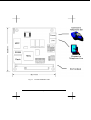
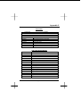
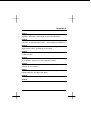
PCM-3601
USER MANUAL
Copyright notice
This document is copyrighted, 2000, by Advantech Co., Ltd. All rights are reserved. The original
manufacturer reserves the right to make improvements to the products described in this manual at any
time without notice.
No part of this manual may be reproduced, copied, translated or transmitted in any form or by any
means without the prior written permission of the original manufacturer. Information provided in this
manual is intended to be accurate and reliable. However, the original manufacturer assumes no
responsibility for its use, nor for any infringements upon the rights of third parties which may result
from its use.
Acknowledgements
AMD is a trademark of Advanced Micro Devices, Inc.
Award is a trademark of Award Software International, Inc.
Cyrix is a trademark of Cyrix Corporation.
IBM, PC/AT, PS/2 and VGA are trademarks of International Business Machines Corporation.
Intel and Pentium are trademarks of Intel Corporation.
Microsoft Windows ® is a registered trademark of Microsoft Corp.
RTL is a trademark of Realtek Semiconductor Co., Ltd.
C&T is a trademark of Chips and Technologies, Inc.
UMC is a trademark of United Microelectronics Corporation.
Winbond is a trademark of Winbond Electronics Corp.
STPC is a trademark of SGS Thomson Corp.
For more information on this and other Advantech products, please visit our website at:
http://www.advantech.com
For technical support and service, please visit our support website at:
http://www.advantech.com/support
This manual is for the PCM-3601.
Part No. 2006360100
1st Edition Printed in Taiwan June 2000
2
Chapter 1
Unpacking and Installation
This chapter describes unpacking and installing your modem.
1.1
Feature
FDSP (Full –duplex speakerphone)
- Acoustic and line echo cancellation
- Microphone gain & muting
- Speaker volume control and muting
Data modem throughput up to 115.2K bps
- V.90
56000, 53333, 51200, 50667, 49333, 48000, 46667,
45333, 44000, 42667, 41333, 40000, 38667, 37333,
36000, 34667, 33333, 32000, 30667, 29333, 28000
bps
- K56flex 56000, 54000, 52000, 48000, 46000, 44000, 42000,
40000, 38000, 34000, 32000 bps
- V.34
33600, 31200, 28800, 26400, 24000, 21600, 19200,
16800, 14400, 12000, 9600, 7200, 4800, 2400 bps
- V.32bis 14400, 12000, 9600, 7200, 4800 bps
- V32
9600,4800 bps
- V.23
1200/75 bps
(originating mode transmit at 75 bps and receive at
1200 bps; answering mode transmit at 1200 bps and
receive at 75 bps)
- V.22bis 2400,1200 bps
- V.22
1200 bps
- V.21
300 bps
- Bell 212A1200 bps
- Bell 103 300 bps
- Automatic modulation negotiation using ITU-T V.8bis/V.8/V.32
Annex A.
Fax modem send and receive rates up to 14400 bps
Page: 1
- ITU-T G3 FAX Modulation
- CLASS 1 & CLASS 2 Command
- ITU-T T.30
- ITU-T V.17
14400 to 9600 bps
- ITU-T V.29
9600 to 4800 bps
- ITU-T V.27ter
4800 to 2400 bps
- ITU-T V.21 Channel2 300 bps
Error Correction & Data Compression
- MNP2 – 4 (ALT)
- MNP5 (ALT/CLASS5)
- V42 (LAPM)
- V42bis (BTLZ)
Voice/audio mode
- Voice transmit mode: PCM or ADPCM
- Enhanced ADPCM compression/decompression
- Tone detection/generation and call discrimination
- Concurrent DTMF detection
- 8-bit monophonic audio data encoding at 11.025K HZ or 7.2K
HZ
NVRAM directory and stored profiles
- NVRAM SIZE:
256byte
- NO OF SCP:
2
- NO OF TEL SET:
4
- Length of each set: 31byte
- Total length:
124byte
Package
- R6764-61
- L2800
100-Pin PQFP (Rockwell)
80-Pin PQFP (Rockwell)
H/W SPEC.
- Freq.
: 28.224 MHz
Page: 2
- Working Currency
- Working Voltage
: 350mA (max)
: DC +5V
: DC+12V
- Working Temperature : 0 – 70 ℃
- Ring Spec.
- Tone Spec.
: +5.50V ~ +4.50V
: +15V ~ 9V
: Fq=15Hz ~ 71Hz, V=35Vrms (above)
: HGF=-4, LGF=-6, ±2db
: HGF=-9, LGF=-11, ±2db(CTR21)
- Pulse Spec.
: M.B.R=39 ±2 , P.P.S=10 ±0.5
- PCB Size
: 96mm X 90mm
EMC & PTT Support: FCC Part15 & Part68/CE/CTR21(Option)
1.2
Unpacking the Modem
The complete modem package should include:
1) The modem unit.
2) This user manual.
3) An RJ-11 to RJ-11 phone cable.
4) Data and fax communications software (Optional).
5) Windows 95/98 Driver
Carefully inspect the package for shipping damage. If damage is
found, repack the modem in the original packing material and
contact your dealer.
1.3
A Look at the Modem Card
Phone: Accepts a Telephone set Connected Parallel to your
Modem.
Line:
Accepts the RJ-11 Cable that links your Modem to a
Telephone line or to a 2-Wire Leased-Line.
PC/104: The PC/104 connectors give you the flexibility to attach
PC/104 modules.
Page: 3
Fig 1-1. PC/104 FaxModem Card
Page: 4
1.4
The Serial Port and Interrupt of the Modem Card
Each peripheral device, such as a modem, uses a port that is
either serial or parallel, depending on its design. Each port can
only accept one device; otherwise, there is a conflict.
Your modem is designed for use with serial ports. You can use any
COM port, COM1 to COM4. Some computers, may support only
two serial ports. See your computer manual for the number of
ports on your computer.
Computers use interrupts (IRQ) to control the data flow between
computers and peripherals. An interrupt signals data to flow or to
stop, much like a traffic light controls the flow of traffic. Each serial
port needs an interrupt to control that particular port.
1.5
Setting the COM Port and Interrupt of the Modem Card
Your modem is factory set for use on COM4 with IRQ3. If you
choose to use it with another serial port or interrupt, you need to
change the COM jumper and IRQ jumper. Make sure the port and
interrupt set-up you use are not used by any other peripheral.
The COM/IRQ settings should appear as in the diagram below. If
you have any questions about setting a port for your modem
consult your dealer.
IRQ
Pin
Jump
Jump
J3
1-2
2-3
J1
J2
IRQ4
COM Port
COM1 (IRQ4)
IRQ3
J4
IRQ5
1-2
1-2
IRQ7
COM2 (IRQ3)
2-3
1-2
J5
IRQ9
IRQ10
COM3
1-2
2-3
J6
IRQ11 IRQ12
COM4
2-3
2-3
J7
IRQ15
Fig 1-2 Modem Card COM/IRQ Setting
1.6
Installing the Modem Card
The modem card is designed for reliability, but it should be kept
away from static electricity, shock, heat, and humidity.
Page: 5
Install the modem into your computer as follows.
1) Turn off the computer
2) Remove the cover of your computer and locate the 5614HP
expansion slot. Refer to your computer installation guide.
3) Plug in your 5614HP modem to the expansion slot, and make
sure the connectors of the modem card are exactly aligned
with the expansion slot.
4) Secure the modem card to the computer with screw.
5) Connect the telephone line from the wall outlet to the jack
labeled LINE.
6) Connect the line from your telephone to the jack labeled
PHONE. You may leave the PHONE jack unconnected.
CAUTION:
Handle the card only by its edges. The card precision components are easily damaged by static electricity or abuse.
The metal bracket of the modem card should rest firmly on
the rear panel bracket of the computer. If not, remove the
modem card and try again.
1.7
Testing the Telephone Line Prior to Connection
The quality of the telephone line significantly affects the reliability
and quality of data communications. Make sure that both the
telephone system and telephone line are in good order before the
modem is connected.
Test the line by lifting the telephone handset and listening for a
clear dial tone. Try placing a few calls. If the calls do not go
through well or are not loud and clear, you may have a poor quality
telephone line. In this case, find a better quality line for your
modem to ensure reliable data communications.
We strongly recommend that you connect the modem directly to
an outside telephone line. Do not connect your modem to a Private
Branch Exchange (PBX) telephone system unless the system is
proven to perform well under data transmission conditions.
1.8
The Communications Software Configuration
Your modem follows the standard modem command set. Most of
Page: 6
the popular communications software packages work with your
modem. If you have any problem using the software, please
contact your software dealer, publisher, or modem dealer.
To install the software, turn on your computer and modem, and
boot the communications software. Follow the software manual
instructions to execute software installation.
Software configuration procedures vary with each software program, computer, and application. Refer to your software manual for
more information. If you experience any difficulty, consult your
dealer.
When installing the software, pay particular attention to the following parameter settings, as many beginners fail to successfully set
them correctly.
1) The serial port number.
2) The communications protocol.
3) The data format, including data bit, stop bit, and parity.
The serial port specified in your communications software must
match the serial port to which the modem is actually connected.
No matter whether it is COM1, COM2, COM3, or COM4, a port
can be only be connected to one peripheral device, and should be
specified so. Otherwise, the two devices will conflict with one
another, or your computer will not be able to find the proper COM
port or other device.
To communicate successfully, the protocol and data format of the
two modems on-line must be identical. For example, if the bulletin
board you are going to dial supports Bell standard, 8 data bits, no
parity, 1 stop bit, you should specify this set-up exactly. Otherwise,
the connection will be unsuccessful and any data received will be
unreadable (garbled).
1.9
Software Configuration Tips
For most PC data communication applications using up-to-date
communication software, the factory default settings are sufficient.
However, you may have to reconfigure your modem if this is not
the case.
Almost all compatible software applications use a similar dialing
prefix command summary. If required, you can use the command
summary to overwrite modem parameters.
Page: 7
Most popular communication software packages allow users to
specify a command string and the dialing prefix that is sent to the
modem prior to dialing telephone number digits. The dialing prefix
reconfigures the modem according to your commands.
Below are some examples of a dialing prefix string:
ATS0=3
Instructs the modem to auto-answer an
incoming call on the third ring.
ATX4DT9W
Instructs the modem to first tone-dial the
number 9 and hold it until a dial tone is
detected.
ATS6=10DP
Instructs the modem to wait for 10 seconds
before proceeding to dial.
ATM2L3DT
Turns on the modem monitoring speaker at all
times, and uses high volume.
ATB0DT
Uses the CCITT protocol to establish
connection with the remote modem.
AT&P1DP
Pulse dials with the make/break ratio of 33/67
(for use in most European countries).
AT&P0DP
Pulse dials with the make/break ratio of 39/61
(for use in the USA).
You may use any command or combination you need. Refer to the
chapters in this manual regarding modem commands for more
details.
1.10 Getting Started
Now, you can dial a bulletin board, data base, or remote computer.
Your modem establishes the connection automatically. Once there
is a connection, you can,
1) read or send electronic mail,
2) view up-to-date news or information,
3) upload or download computer programs,
4) transmit or receive a text message or spread sheet data, or,
perform whichever on-line data communication tasks you
require.
Note that the remote modem should be set to accept digital
loopback request by issuing AT&T4.
Page: 8
Chapter 2
Modem Fundamentals
This chapter provides a brief overview of how modems work.
2.1
Modem Basics
Modems let computers communicate with other computers using
normal telephone lines or leased lines. Your modem sends
communications by modulating (converting) data into sound waves
that a telephone can transmit and another modem can receive.
Your modem receives communications by demodulating sound
waves from the telephone into data your computer can recognize.
The term modem is an abbreviated way of describing this
modulation/demodulation process.
In addition to converting data to sound, a modem performs
functions such as dialing, answering calls, and adjusting settings
for local telephone conditions. Commands must be issued to the
modem to control these functions and settings.
2.2
Data Format
In asynchronous serial communications, data bytes are
disassembled into individual bits and then transmitted bit by bit
along with interval bits and checksum bits, in the order of start bit,
data bits, parity, stop bits, and so on.
The interval bits, start bit, and stop bit, signal to the receiving party
the beginning and end of a byte. The checksum bit and parity allow
the receiving party to check the accuracy of the received data.
The pattern in which a byte is disassembled is called the data
format. Modems at both ends of a link should use the same data
format. Otherwise, the data may be misinterpreted and appear
garbled.
The most commonly used data formats include the following types.
Before you dial a bulletin board or connect on-line with any remote
modem, make sure your modem supports the required data format,
your software can specify the required data format, and that you
have specified the correct data format.
Start Bit
Data Bits
Parity
Page: 9
Stop Bit
Total
1
1
1
1
2.3
8
7
7
7
none
none
even, odd
mark, space
1
2
1
1
10
10
10
10
Communications Protocol
Two popular groups of communications protocol are currently used
in data communications throughout the world, the Bell standard
and the CCITT recommendation. For 1200bps protocols, the Bell
standard is used mainly in the United States and Canada, while
the CCITT standard is used in most other countries. For 2400bps
and faster protocols, the CCITT standards are used internationally.
The following table shows common communications protocols
listed from the highest to the lowest DCE speed.
DCE Speed
Bell
CCITT
56000bps
33600bps
28800bps
14400bps
9600bps
2400bps
1200/75bps
75/1200bps
1200bps
0-300bps
N/A
N/A
N/A
N/A
N/A
N/A
N/A
N/A
212A
103
V.90
V.34+
V.34
V.32bis (TCM)
V.32 (QAM & TCM)
V.22bis
V.23 Main (host)
V.23 Back (user)
V.22
V.21
Synchronous
async
async
async
async
async
async
async
async
async
async
Data communications requires that both modems on a link use the
same protocol. The protocol determines the communications
speed and transmission standard (Bell or CCITT). To change
protocols, you can issue a B command and the modem automatically goes to the highest speed of that protocol. If you want to
specify a particular protocol speed, issue a %B command.
2.4
Speeds of the Modem
During an on-line communications path, your modem is located
between the local computer and remote modem. It has to
Page: 10
communicate with both the remote modem and local computer,
through the telephone line and serial port cable, respectively.
Figure 1-1 describes the DCE speed relationship between
modems.
The speed over the telephone line at which your modem
communicates with the remote modem is called the on-line speed.
Since the modem is Data Communications Equipment, the
communications speed is called the DCE speed.
On the other hand, the speed over the serial port at which your
modem communicates with the local computer is called the serial
port speed. Since the computer is Data Terminal Equipment, it is
called the DTE speed.
2.5
On-Line Speed (DCE Speed)
Your modem supports one or more communication protocols,
depending on its modem type. When your modem answers a call
and establishes a connection, it adjusts its speed according to that
of the calling modem. As a result, the speed at which the calling
modem dials becomes the on-line speed.
2.6
Serial Port Speed (DTE Speed)
Each time the modem receives a command string from the
computer, the AT prefix instructs the modem of the serial port
speed. This speed remains as the active serial port speed, (i.e.,
the active speed DTE speed).
For example, if your modem is set at 2400bps and the remote
modem is calling at 1200bps, the connection is established at
1200bps. Your modem sends the response code CONNECT
1200” at 2400bps to the local computer and then adjusts its DTE
speed to 1200bps. Your modem will no longer recognize
characters received from the local computer at 2400bps. If you are
writing communications software, be sure to have the local
computer determine the speed from the response code and adjust
its serial port speed accordingly.
In normal applications, the baud rate adjustment capability of your
modem should be enabled so that the DTE speed shall always
follow the DCE speed. you can issue the \J command to turn the
serial port adjustment on or off.
Page: 11
However, in a reliable link or a direct link the baud rate adjustment
capability may be disabled, so that the serial port speed may be
different to the on-line speed. If data comes in faster than it goes
out, the faster incoming data is stored in the data buffer.
Therefore, when flow control capability is enabled, it is advisable
that the on-line (DCE) speed be at a rate equal to or higher than
the serial (DTE) port speed. Otherwise, data may be lost after the
buffer is full.
2.7
Error-Correction and Data Compression (ECDC)
Many modems support error-correction and data compression
(ECDC) protocols. Error-correction assures error-free data
transmission because the modem re-transmits the incorrect block
of data once a transmission error is detected. Data compression
can increase data throughput which results in savings of
transmission time and telephone bill costs. Common ECDC
protocols include CCITT V.42, V.42bis, and MNP 2-5.
The CCITT V.42 recommendation offers an error-correction
protocol referred to as LAPM (Link Access Procedure for Modems),
which is the modem protocol for point-to-point communications.
The CCITT V.42bis provides both error-correction and data
compression features. In addition to its compatibility to V.42 in
error-correction, V.42bis offers a 4:1 data compression rate so that
data can be transferred up to 4 times faster than a non-MNP
modem. For example, a 14,400bps modem can reach a data
throughput of 57,600bps when the compression rate is 4:1 on a
V.42bis ECDC link. However, the true compression rate depends
on the pattern of the transmission file.
As an alternative to CCITT recommendations, MNP Class 2 to 4
offers error-correction capability, while MNP Class 5 offers a 2:1
data compression. The MNP protocol was popular before CCITT
ECDC protocols were released and there are still some modems
using this protocol.
Note that V.42/V.42bis and MNP are different both in format and
operation. Two modems must support the same ECDC protocol in
order to connect in ECDC mode. For example, a V.42bis modem
connects in V.42bis mode only when the remote modem also
supports the V.42bis protocol. For example, if your modem
supports all three ECDC protocols, but the remote modem only
Page: 12
supports MNP5, the connection can only be established in MNP5
mode.
You should use the V.42bis recommendations as long as the online modem at the remote end supports the same. This way, you
can achieve higher data throughput. To select the ECDC mode,
use the command \N.
2.8
Flow Control
While on-line, your modem is between your computer and the
remote modem (or the remote computer, if you consider the
remote modem as a transparent device). Your modem
communicates with your computer (the local computer) through
RS-232 serial port interface, and communicates with the remote
modem via telephone line.
If data comes to your modem faster than it goes out, some data
may be lost because your modem can not pass on all the received
data to the other end. To overcome this problem, your modem is
equipped with a data buffer to store excess data received. Once
the buffer is full, your modem must signal the sending device to
stop transmission. When the buffer is clear, your modem signals to
resume data transmission. This is called flow control.
Two kinds of flow control methods are commonly used, the
hardware flow control and the software flow control. Hardware flow
control is also called RTS/CTS control, as it uses the RS-232
hardware signals (RTS and CTS) to stop or resume data
transmission. This is the best method of flow control because you
can send any data characters using this method.
The software flow control uses two data characters (XON and
XOFF) to indicate when the sending device shall stop or resume.
Since it uses data characters as control, you can not send binary
data or file-transfer protocols such as XMODEM with this type of
flow control. To select a method for flow control, use command \Q.
You should use hardware flow control at all times, if your modem
supports it.
2.9
Non-Volatile Memory (NVRAM)
The NVRAM is a special type of read-write memory element which
can retain data even when the power is turned off. Your modem
NVRAM retains configuration profiles and telephone numbers.
Page: 13
The NVRAM does not require a back up battery so that you can
eliminate the threat of data loss due to a dead battery, as well as
avoid hardware damage due to electrolyte leakage.
2.10 Factory Default Profile (FDP)
The FDP is the default configuration profile stored in your modem
read-only memory (ROM), which can not be modified by the user.
The FDP is intended for rescuing the modem in case the user
misconfigures the modem settings.
To display the FDP, use command &F to place the profile into the
active configuration area (ACA), then issue AT&V. Note that some
modems may have more than one built-in FDP; in which case,
each FDP serves as the default for a particular application
requirement.
2.11 Stored Configuration Profile (SCP)
The SCP is the configuration profile stored in the NVRAM of the
modem to be retrieved for later use.
Initially the factory sets the SCPs identically to the FDPs. To view
all the SCP configurations, issue command &V. note that once an
SCP is selected and loaded into ACA, it becomes the major SCP
and provides the control characteristics of the modem.
If you hav edited the ACA and wish to write it to an SCP, issue a
&W command. The modified configuration profile overwrites the
original SCP and becomes the new SCP.
For information on the SCPs of your particular modem, refer to
your Getting Started manual.
2.12 Major Stored Configuration Profile (Major SCP)
The major SCP is the SCP that is loaded into the ACA each time
the modem is turned on or reset by ATZ. To designate an SCP as
the major SCP, issue &Y followed by the SCP number. For
example, issuing &Y1 designates SCP1 as the major SCP.
2.13 Active Configuration Area (ACA)
The ACA is a portion of the random-access-memory (RAM) in your
modem that holds the configuration settings that determine the
modem current operating characteristics.
Page: 14
When the modem is turned on or reset by command ATZ, the ACA
is first loaded with the FDP, and then is overwritten by the major
SCP. The commands you issue to the modem actually change the
contents of the ACA. However, once the modem is turned off, all
the settings in the ACA vanish.
To save the current ACA configuration to a SCP for further use,
issue command &W followed with the number of the SCP. For
example, issue &W1 saves the current configuration to SCP1.
The next time you want to use the same configuration, just issue
AT&1 to load the ACA with the SCP1 previously saved.
Issuing &V0 command displays the current configuration profile,
the stored configuration profiles, as well as the current speed, data
format, parity and protocol.
2.14 Stored Telephone Numbers (STN)
The STN are the digits retained in the modem NVRAM and used
for speed dialing. You may use it to save frequently used
telephone numbers, passwords, or credit card numbers.
To store a telephone number as an STN, use &Z followed by the
STN number, the"=" sign, and the telephone number. For example,
&Z2=886-2-2782-0305 stores 886-2-2782-0305 as STN2.
Note that only digits can be stored in STN. Other characters or
symbols are discarded.
To view the STN, issue command &V1. To dial an STN, issue S=n,
where n denotes the nth STN. For the example above, issuing
ATDS=2 instructs the modem to dial 886-2-2782-0305.
Page: 15
Chapter 3
Modem Operation and Response Codes
This chapter describes modem states, commands and response
codes and explains how to issue commands to the modem.
3.1
Command State and Data State
During operation, your modem is either in command state or data
state. The figure below shows the relationships between the two
states and how to enter and abort from each of them.
In command state, the modem interprets all the characters it
receives as commands. The command state may either be on-line
or off-line. When the modem is holding a connection with a remote
modem or when it is in an analog loopback test, it is on-line.
Otherwise, it is off-line.
In data state, the modem is a transparent receiving and sending
device. It assumes everything it receives (except the escape
sequence) as data and conveys them to the local computer or
remote system.
3.2
The Escape Sequence (+++)
The escape sequence instructs the modem to leave (escape) the
data state and enter the command state, without breaking the
connection. It is the only data string that is interpreted as a
command when the modem is in data state.
After switching to command state, the user can issue further
commands, such as changing parameter settings, etc. To resume
data state, simply issue ATO.
The escape command in default is three consecutive “+”
characters. For the modem to distinguish the escape command
from the data, a certain duration of guard time is defined to exist
both prior to and after the three consecutive escape characters.
The escape sequence includes a guard time, three consecutive
escape characters, and a guard time, in that order.
The default guard time is 1 second. It can be changed by
assigning a different value to register S12.
In the same manner, you may change the escape character to a
Page: 16
different one by assigning the ASCII value (in decimal) of the new
escape character to register S2.
3.3
Issuing Commands
When the modem is in command state, you can issue commands
to the modem by typing them on the keyboard. A command line
shall always begin with AT (or at), followed by the command or
commands, and completed with a return key. The only exception is
A/, which does not require the AT prefix and a return key.
Some commands, such as M1, M2 or M3, require a parameter
after the command letter. If the parameter is missing, the modem
treats the command as having a parameter of 0. For example, M
would be recognized as M0.
When multiple commands are issued in a command line, you can
insert spaces between commands to make the command line
easier to read.
3.4
Command Buffer
The command buffer has a capacity of 40 characters. All the
commands you type on the keyboard are stored in the command
buffer before the return key is pressed. However, the AT or at, the
carriage return, the optional line feed characters, and the spaces in
the command line are not stored in the command buffer.
The command line stored in the command buffer is not executed
until you have pressed the return key. If the command buffer
overflows, the modem sends the ERROR response code upon
receiving the carriage return character, and all the commands in
the command buffer are ignored.
3.5
Deleting Commands
If you make a mistake while typing a command line, you can press
the backspace key to delete the last character you have entered.
However, the backspace key does not delete the AT prefix.
To delete the entire command line, press the backspace key until
every command character (except AT) is deleted. Then, press the
return key.
You may change the backspace character to another ASCII
character by assigning a new value to register S5. For example,
Page: 17
ATS5=27 designates ESC as the backspace character.
3.6
Modem AT Response Codes
Unless you have instructed the modem not to send response
codes by issuing command Q1, it will always send a response
code after executing a command line. The response code can be
displayed in word or in digit form depending on the V command
issued.
Command X0 to X4 lets you select different response sets of the
modem, which enables or disables certain response codes. In
general application, you can select X4, the default, which enables
all response codes so that the most specific response message
can be displayed. If you plan to write your own software for special
applications, you may select the response set you require by
issuing an appropriate X command.
The following table shows the response codes from 0 to 8 related
to each command. The means the response code is disabled for
the corresponding command. The remaining response codes are
enabled.
Page: 18
Chapter 4
AT Commands
This chapter describes the basic modem commands in alphabetical order.
Some commands have factory default settings, for which you can refer to
your Getting Started manual Command Summary table.
4.1
Prefix, Repeat and Escape Commands
AT Attention. Precede all command lines except A/ and +++
A/ Re-execute the last command in command buffer
+++ Escape characters, requires guard time before and after
4.2
Dial Commands and Dial Modifiers
D
S=n
T
P
R
Originate a call
th
Dial the n stored number
Touch tone dialing
Pulse dialing
Dial
in
answer
mode
4.3
Operation Commands
A
Answer incoming call
B0
B1
CCITT or ITU-T compatibility
Bell protocol only
E0
E1
Disable command echo
Enable echo command
characters
H0
Hang up the connection (onhook)
Go off-hook to make a call
H1
I0
I1
I3
Reports product code
Calculates the ROM
checksum
Reports firmware version
L0
L1
L2
L3
Low volume
Low volume
Medium volume
High volume
M0
M1
Speaker off at all times
Speaker on until CD
W
L
,
!
;
M2
N0
N1
O0
O1
Q0
Q1
Wait for second dial tone
Re-Dial the last valid
telephone number
Pause
Flash
Return to command state
detected
Speaker always on
Fixed data rate follow *N
command
Enable adaptive data rate
Return to data-link without
retrain
Return to data-link with
retrain
Modem sends response
codes
Do not send response codes
Sr? Display the value in register
Sr=n Set register r to a value n
V0
V1
W0
Page: 19
Display response codes in
digit form
Display response codes in
words
Disable V.42 response codes,
W1
display DTE speed
Enable V.42 response
codes, display DCE speed
W2
Disable V.42 response codes,
display DCE speed
X0
Enable basic response
codes 0-4
Do not detect dial tone and
busy signal
Include dial tone detection
response
Include busy detection
response
Enable all response codes
X1
X2
X3
X4
Y0
Y1
Z0
Z1
Do Not send (and ignore)
break signal
Send break signal for 4
seconds before disconnect
Reset modem with SCP0
Reset modem with SCP1
&C0 Turn CD signal to always on
&C1 CD on at remote carrier
detected
&D0 Alone with any of following
&Q0, &Q5, &Q6 then, DTR is
not functional.
Alone with any of following
&Q1, &Q4 then DTR drop
causes the modem hang up,
Auto-answer is not affected.
Alone with any of following
&Q2, &Q3 DTR drop causes
the modem to hang up, AutoAnswer is inhibited
&D1 Alone with any of following
&Q0, &Q1, &Q4, &Q5, &Q6
DTR drop is interpreted by
the modem as if the asynchronous escape sequence
had been entered. the
modem return to
asynchronous command
state without disconnecting.
Alone with any of following
&Q2, &Q3 DTR drop causes
the modem to hang up. AutoAnswer is inhibited.
&D2 Alone with any of follo-wing
&Q0 through %Q6 then,
DTR drop causes the
modem to hang up AutoAnswer is inhang.
&D3 Alone with any of following
&Q0, &Q1, &Q4, &Q5, &Q6
DTR drop causes the modem
to perform a softre-set as if
the z command were
received. The & Y setting
determines which profile is
loaded.
Alone with any of following
&Q2, &Q3 DTR drop causes
the modem to hang up AutoAnswer is inhibited.
Note: &D0 Ignore DTR & Ignore
dialing key-abort.
&F0 Restore factory default profile
FDP0 (as ECDC modem)
&F1 Restore factory default profile
FDP1 (as non-ECDC modem)
&G0 Disable guard tone
&G1 Disable guard tone (default
for us models)
&G2 Enable 1800 Hz guard tone
&Ln Leased line dial line operation
&L0 Dial-Up line operation
&L2 Leased line operation
&K0 Disable flow control
&K3 RTS/CTS flow control
&K4 XON/OFF flow control
Page: 21
&K5 Unidirectional XON/OFF
&K6 RTS/CTS, XON/XOFF flow
control
&M0 Set modem for async
operation
&P0 M/B ratio 39/61(USA)
&P1 M/B ratio 33/67(UK, Hong
Kong)
&P2 M/B ratio 39/61 at 20 pulses
&P3 M/B ratio 33/67 at 20 pulses
&Q0 See & M0
&Q5 The modem will try to
negotiate an error-corrected
link
&Q6 Select asynchronous
operation in normal mode
&R0 Modem turns CTS on when
detects RTS from the local
computer
&R1 Ignore RTS. Modem turns
CTS on when ready to
receive synchronously
&S0 Modem forces DSR always
on
&S1 Set DSR to follow RS-232
spec
&T0
&T1
&T5
&T8
&V
loopback, V.34 Loop3, Sets
S16 bit0. If aconnect exists
when this command is issued,
the modem hangsup, The
connect xxxx message is
displayed upon the start of
the test.
Disable digital loopback
acknowledgment for
remote request.
Initiates local analog
loopback, V.34 Loop3, with
selftest.
Display modem profiles and
numbers
&W0 Write ACP to SCP0
&W1 Write ACP to SCP1
&Y0 Designate SCP0 as the
active SCP
&Y1 Designate SCP1 as the
active SCP
&Zn= Save up to three numbers to
NVRAM. Use DS=n to dial
the stored number
Note: &Q,&M: for Sync mode only
Terminates test in progress
Initiates local analog
Page: 22
4.4
Call Back Security Command Set
Option
$DTXCn
n=0, 1,2
n=0 Disable Call Back Security (Default)
n=1 Enable Call Back Security
n=2 Display current status
$DTXP=XXXXXXXX Set Password (MAX 8 chars)
P? Display Password
$DTXN=n Set call back redial count (n=1~31 default: 3)
N? Display call back redial count
$DTXT0=n Set call back delay time
T?
Display call back delay time (n=10~255 Sec.
Default: 10)
$DTXT1=n Set time-out time
T?
Display time-out time (n=30~255 Sec. Default:
60)
4.5
&Ln
&L0
&L1
4.6
Lease Line/Dial Line command set
Option
n=0,1
Disable Lease Line mode, select dial line mode.
(Default)
Disable Dial line mode, select lease line mode.
Lease Line Backup Dial Line command set
Option
$DTXB=0 Disable Lease Line Backup Dial Line.
$DTXB=n Enable Lease Line Backup Dial Line (n=1~255 min.
default: 10)
$DTXB? Display current status.
Page: 23
4.7
Display Dialing Number (if AT&In Command support)Option
$DTXAn
4.8
&In
n=0,1
n=0 Disable display Dialing number. (Default)
n=1 Enable display Dialing number.
A? Display Current status.
Auto Dial/Redial mode
Option
n=0, 1, 2, 3
n=0 Disable auto dial/redial mode. (Default)
n=1 auto dial/redial &Z0.
n=2 auto dial/redial &Z0, &Z1, &Z2, &Z3.
n=3 auto dial/redial last dial number.
Page: 24
Chapter 5
V.42bis and MNP Command
This chapter explains ECDC commands and Extended commands,
which are in addition to the basic modem commands listed in the
previous chapter. Some commands have a factory default setting.
Refer to your Getting Started manual for information on default
settings.
5.1
Maximum ECDC Block Size
\A0
\A1
\A2
\A3
5.2
5.3
MNP block size 64 characters
MNP block size 128 characters
MNP block size 192 characters
MNP block size 256 characters
Transmit Break
\Bn
[\B]
Send n/10 seconds of line break to the modem (n
= 0 ~ 9, default 3)
Set Break Control
\K0
\K1
\K2
\K3
\K4
\K5
[\A]
[\K]
Enter command mode, do not send a break signal
to remote (To send a break after use the \B
command)
Clear data buffer and send a break
Same as \K0
Immediately send a break
Same as \K0
Send a break in sequence with any data
received from the port
Page: 25
5.4
ECDC Operation Mode Selection
\N0
\N1
\N2
\N3
\N4
5.5
\V1
5.6
[%C]
Disable data compression
Enable MNP5 data compression negotiation
Enable V.42bis data compression
Enable both V.42bis and MNP5 data compression
(default)
Automatic Retrain
%E0
%E1
%E2
[\V]
Connect messages are controlled by the command
settings X, W, and S95.
Connect message displayed in the single line
format described below subject to the command
settings V (Verbose) and Q(Quiet). In NonVerbose mode(V0), single line connect messages
are disabled and a single numeric result code is
generated for CONNECT DTE.
Data Compression
%C0
%C1
%C2
%C3
5.7
Set modem to normal mode
Set modem to direct mode
Set modem to MNP reliable mode
Set to MNP/V.42 auto-eliable mode
V.42 reliable with phase detection
MNP Response Code Option
\V0
[\N]
[%E]
Disable auto-retrain
Enable auto-retrain
Enable fallback/fall forward
Page: 26
Appendix A
Modem Register
The registers of the modem determine its operation characteristics.
This chapter describes the modem registers, except for those
reserved registers that can not be modified by the user.
S-Register Summary ___________________________________
Register
S0
S1
S2
S3
S4
S5
S6
S6
S7
S8
S9
S10
S11
S12
S13
S14
S15
S16
Range
0-255
0-255
0-255
0-127
0-127
0-255
2-255
5-6
1-255
0-255
1-255
1-255
50-255
0-255
-
Units
Rings
Rings
ASCII
ASCII
ASCII
ASCII
s
s
s
s
0.1s
0.1s
0.001s
0.02s
-
Default
0
0
43
13
10
8
2
6
50
2
6
14
95
50
138(8Ah)
0
S17
S17
S18
S19
S20
0.255
0-255
s
-
192(C0n)
64(40n)
0
0
0
S21
-
-
52(34h)
S22
-
-
117(75h)
S23
S24
0-255
s
62(3Dh)
0
Function
Rings to Auto-Answer
Rings Counter
Escape character
Carriage return character
Line Feed Character
Backspace character
Wait Time for Dial Tone
Wait Time for Dial Tone (for CTR21)
Wait Time for Carrier
Pause Time for Dial Delay Modifier
Carrier Detect Response Time
Carrier Loss Disconnect Time
DTMF Tone Duration
Escape Prompt Delay
Reserved
General Bit Mapped Options Status
Reserved
Test Mode Bit Mapped Options
Status(&T)
Redial options status (&I)
Redial options status (&I) (for CTR21)
Test Timer
AutoSync Options
AutoSync HDLC Address or BSC
Sync Character
V.24/General Bit Mapped Options
Status
Speaker/Results bit Mapped Options
Status
General Bit Mapped Options Status
Sleep Inactivity Timer
Page: 27
Register
S25
S26
S27
S28
S29
S30
S31
S32
S33
S34-S35
S36
S37
S38
S39
Range
0-255
0-255
0-255
0-255
0-255
0-255
0-255
-
Units
s or 0.01s
0.01s
10ms
10s
ASCII
ASCII
s
-
S40
S41
S42-S45
S46
S48
S82
S86
S91
0-255
0-15
dBm
S92
0-15
dBm
S95
-
-
Default
5
1
73(49h)
0
70
0
194(C2h)
17(11h)
19(13h)
7
0
20
3
Function
Delay to DTR Off
RTS-to-CTS Delay
General Bit Mapped Options Status
General Bit Mapped Options Status
Flash Dial Modifier Time
Disconnect Inactivity Timer
General Bit Mapped Options Status
XON Character
XOFF Character
Reserved
LAPM Failure Control
Line Connection Speed
Delay Before Forced Hang-up
Flow Control Bit Mapped Options
Status
168(a8h)
General Bit Mapped Options Status
195(C3h)
General Bit Mapped Options Status
Reserved
138
Data Compression Control
7
V.42 Negotiation Control
128(40h)
LAPM Break Control
Call Failure Reason Code
10(country PSTN Transmit Attenuation Level
dependent)
10(country Fax Transmit Attenuation Level
dependent)
0
Result Code Messages Control
♦=Register value may be stored in one of two user profiles with the &W command.
Page: 28
Appendix B
Result Codes
Short Form
0
1
2
3
4
5
6
7
8
9
10
11
12
13
14
15
16
17
18
19
20
22
23
24
32
33
35
40
44
45
46
47
48
49
50
51
52
53
54
55
56
Long Form
OK
Connect
Ring
No Carrier
Error
Connect 1200
No dial tone
Busy
No Answer
Connect 600
Connect 2400
Connect 4800
Connect 9600
Connect 7200
Connect 12000
Connect 14400
Connect 19200
Connect 38400
Connect 57600
Connect 115200
Connect 230400
Connect 75TX/1200RX
Connect 1200TX/75RX
Delayed
Blacklisted
Fax
Data
Carrier 300
Carrier 1200/75
Carrier 75/1200
Carrier 1200
Carrier 2400
Carrier 4800
Carrier 7200
Carrier 9600
Carrier 12000
Carrier 14400
Carrier 16800
Carrier 19200
Carrier 21600
Carrier 24000
0
x
x
x
x
x
1
3
3
x
1
1
1
1
1
1
1
1
1
1
1
x
1
1
4
4
x
x
x
x
x
x
x
x
x
x
x
x
x
x
x
x
n Value in ATXn Command
1
2
3
4
x
x
x
x
x
x
x
x
x
x
x
x
x
x
x
x
x
x
x
x
x
x
x
x
3
x
x
x
3
3
x
x
x
x
x
x
x
x
x
x
x
x
x
x
x
x
x
x
x
x
x
x
x
x
x
x
x
x
x
x
x
x
x
x
x
x
x
x
x
x
x
x
x
x
x
x
x
x
x
x
x
x
x
x
x
x
x
x
x
x
x
x
4
4
4
x
4
4
4
x
x
x
x
x
x
x
x
x
x
x
x
x
x
x
x
x
x
x
x
x
x
x
x
x
x
x
x
x
x
x
x
x
x
x
x
x
x
x
x
x
x
x
x
x
x
x
x
x
x
x
x
x
x
x
x
x
x
x
x
x
x
x
x
x
Page: 29
Notes
Short Form
57
58
59
61
62
63
64
66
67
69
70
77
78
79
80
81
84
91
150
151
152
153
154
155
156
157
158
159
160
161
162
165
166
167
168
169
170
171
172
173
174
175
176
177
+F4
Long Form
Carrier 26400
Carrier 28800
Connect 16800
Connect 21600
Connect 24000
Connect 26400
Connect 28800
Compression: Class 5
Compression: V.42bis
Compression: None
Protocol: None
Protocol: LAPM
Carrier 31200
Carrier 33600
Protocol: ALT
Protocol: ALT-Cellular
Connect 33600
Connect 31200
Carrier 32000
Carrier 34000
Carrier 36000
Carrier 38000
Carrier 40000
Carrier 42000
Carrier 44000
Carrier 46000
Carrier 48000
Carrier 50000
Carrier 52000
Carrier 52000
Carrier 56000
Connect 32000
Connect 34000
Connect 36000
Connect 38000
Connect 40000
Connect 42000
Connect 44000
Connect 46000
Connect 48000
Connect 50000
Connect 52000
Connect 54000
Connect 56000
+FCERROR
0
x
x
1
1
1
1
1
x
x
x
x
x
x
x
x
x
1
1
x
x
x
x
x
x
x
x
x
x
x
x
x
x
x
x
x
x
x
x
x
x
x
x
x
x
x
n Value in ATXn Command
1
2
3
4
x
x
x
x
x
x
x
x
x
x
x
x
x
x
x
x
x
x
x
x
x
x
x
x
x
x
x
x
x
x
x
x
x
x
x
x
x
x
x
x
x
x
x
x
x
x
x
x
x
x
x
x
x
x
x
x
x
x
x
x
x
x
x
x
x
x
x
x
x
x
x
x
x
x
x
x
x
x
x
x
x
x
x
x
x
x
x
x
x
x
x
x
x
x
x
x
x
x
x
x
x
x
x
x
x
x
x
x
x
x
x
x
x
x
x
x
x
x
x
x
x
x
x
x
x
x
x
x
x
x
x
x
x
x
x
x
x
x
x
x
x
x
x
x
x
x
x
x
x
x
x
x
x
x
x
x
x
x
x
x
x
x
x
x
x
x
x
x
x
x
x
x
x
x
x
x
x
x
x
x
Page: 30
Notes
Short Form
Long Form
0
n Value in ATXn Command
1
2
3
4
Notes
Notes:
An “x” in a column indicates that the message (either the long form if verbose, or the value
only for short form) will be generated when that particular value of “n” (shown at the top of
the column) has been selected by the use of ATXn. If the (verbose or short form) will be
output for that X option.
Page: 31
Appendix C
Fax Command Codes
Fax Class I
Command
+FCLASS=
+FAE=n
+FTS=n
+FRS=n
+FTM=n
+FRM=n
+FTH=n
+FRH=n
Function
Service Class ID
Service Class
Fax Class 1 Commands
Data/Fax auto Answer
Stop Transmission and Wait
Receive Silence
Transmit Data
Receive Data
Transmit Data with HDLC Framing
Receive Data with HDLC Framing
Fax Class II Commands
Command
+FCLASS=n
+FAA=n
+FAXERR
+FBOR
+FBUF?
+FCFR
+FCLASS=
+FCON
+FCIG
+FCIG:
+FCR
+FCR=
+FCSI:
+FDCC=
+FDCS:
+FDCS=
Function
Service class
Adaptive answer
Fax error value
Phase C data bit order
Buffer size (read only)
Indicate confirmation to receive
Service class
Facsimile connection response
Set the polled station identification
Report the polled station idendification
Capability to receive
Capability to receive
Report the called station ID
DCE capabilities parameters
Report current session
Current session results
Page: 32
+FDIS:
+FDIS=
+FDR
+FDT=
+FDTC:
+FET:
+FET=N
+FHNG
+FK
+FLID=
+FLPL
+FMDL?
+FMFR?
+FPHCTO
+FPOLL
+FPTS:
+FPTS=
+FREV?
+FSPL
+FTSI:
Report remote capabilities
Current sessions parameters
Begin or continue phase C receive data
Data transmission
Report the polled station capabilities
Post page message response
Transmit page punctuation
Call termination with status
Session termination
Local ID string
Document for polling
Identify model
Identify manufacturer
Phase C time out
Indicates polling request
Page transfer status
Page
Identify revision
Enable polling
Report the transmit station ID
Page: 33
Appendix D
Installation of Modem Driver in Win 95/98
STEP 1.
Turn on computer. Move mouse to “Start” at left hand side, enter
“Setting-s” and select “Control panel” go to Next Windows.
STEP 2.
Under “Control Panel” select “Modems”. (or Move mouse to “My
computer” at right hand side, enter “Control panel and Modems”.)
STEP 3.
In Install New Modem, please tick “Don‘t detect my modem; I will
select it from a lost”, and then go to next step.
STEP 4.
Because the modem is not listed, you click “Have Disk” for other
modem models.
STEP 5.
Insert the installation disk or CD-ROM into the driver selected,
click “Browse”, select one of the PCM-3601.inf files.
STEP 6.
Click the manufacturer and model of your modem, please select it
and then go to next step.
STEP 7.
Select the port to use with this modem, for example the modem
setting COM port, and then click “Next”.
STEP 8.
Your modem has been set up successfully. Click “Finish”.
STEP 9.
Select the modem you have, and then click “Close”.
Page: 34