1
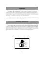
Owners' manual
PORTABLE AIR CONDITIONER
Serie MUPO-11-RE
CODE: CL 20 095
Please read this manual carefully before operating the unit
SUMMARY
1. SUMMARY .................................................1
2. WORKING PRINCIPLE.......................................1
3. SAFETY LABELS OF THE UNIT...............................2
4. SPECIFICATIONS ...........................................3
5. STRUCTURE................................................4
6. OPERATING METHODS ................................5 --12
※.USAGE NOTICE
.........................................5 --7
※.FUNCTIONS OF DISPLAYER AND PANEL
.................8--10
※.NAMES AND FUNCTIONS OF PARTS OF WIRELESS REMOTE CONTROL ..11--12
7. ACCESSORIES AND INSTALLATION OF HEAT EXHAUST HOSE
...13-- 20
8. ACCESSORIES AND INSTALLATION OF DRAINAGE HOSE .........21
9. CHANGE METHOD OF WHEELS.............................22
10. CARE AND MAINTENANCE
..........................23 --24
11. TROUBLESHOOTING......................................25
12. USER NOTICES .....................................26 -- 27
13. AFTER SALES SERVICE...................................27
14. CIRCUIT DIAGRAM........................................28
SUMMARY
This MOBILE AIR CONDITIONER is a small, moveable air conditioner. It possessed the
functions of COOL, HEAT, DRY and the Separate Ventilation, and depends on different places, it
can be moved as will. It is fit for home and office use, especially fit for the house with many rooms.
With the compact configuration, excellent workmanship, elegant appearance, it looks like a standing
Benz car. It is convenient for moving, energy saving, and with low noise.
Note: Please read this manual carefully before operating the unit, the manual is used for reference,
and the technical parameters are subject to change without notice.
WORKING PRINCIPLE
With the help of upper motor, the airflow of indoor pass through the evaporator becomes the
cooled wind, but with the help of lower motor, the airflow of indoor pass through the condenser
becomes the heated wind. There is two duct systems designed in its structure. The heated wind is discharged
by the rear outlet, the cooled wind is discharged by the front outlet, flow-guided by the louver, and it
brings the gentle cooling airflow, and the low temperature environment is maintained.
The Working Principle
Cooled wind
Evaporator
Upper motor
Airflow 1
Capillary
Heated wind
Lower motor
Airflow 2
Condenser
-1-
SAFETY LABELS OF THE UNIT
Your safety and the safety of others are very important.
We have provided many important safety messages in this manual and on your appliance. Always read and
obey all safety messages.
This is the safety alert symbol.
This symbol warns you to the potential hazards that can kill or hurt you and others.
All safety messages will follow the safety alert symbol and either the word "DANGER"
or "WARNING." These words mean:
You can be killed or seriously injured if
you don't immediately follow instructions.
You can be killed or seriously injured if
you don't follow instructions .
All safety messages will tell you what the potential hazard is, how to reduce the chance of injury, and
what will happen if the instructions are not followed.
-2-
-3 -
230V
50Hz
6.0
Rated voltage
Rated frequency
Cooling rated current (A)
885×761×460
Package dimension (H×W×D) (mm)
Note: 1. Cooling capacity is tested when indoor temp. dry bulb 27℃ and wet bulb 19℃(indoor outside is the
same) without air outlet pipe.
2. Heating capacity is tected when indoor temp. dry bulb 20℃ and wet bulb 12℃.
3. Max. input power is tested under cooling mode when indoor temp. dry bulb 35℃ and wet bulb 24℃.
4. Noise is tested 1m in front of front air outlet vent under cool air state, it is sound press grade.
5. Please refer performance parameter on nameplate as standard. The design are subject to be
changed without notice.
840×546×405
47kg
Dimension (H×W×D) (mm)
Weight (N.W.)
59
Noise (sound press)(cool air outlet)(dB)
570
Airflow (m3/h)
R410A 1050g
1610
Max. imput power (W)
Refrigerant and charge amount
2450
1380
Heating rated power (W)
Cooling rated power (W)
7.0/12.8
2400
Heating capacity (W)
Max. cooling/Heating input current (A)
12000
GPEN12A5NK3BA
Cooling capacity (BTU)
Models
SPECIFICATION
STRUCTURE
Front
Control panel
Air outlet
Handle
Rear
Upper air inlet grille
Heat air exhaust vent
Power cord
Lower air inlet grille
-4 -
OPERATING METHODS
※.Usage notice
The working range of COOL The working range of COOL mode is 16℃-35℃.
mode and DRY mode
Unpack the Air Conditioner
WARNING
Excessive Weight Hazard
Use two or more people to move and install the air conditioner.
Failure to do so can result in back or other injury.
Remove packaging materials
Remove and properly dispose the packaging materials. Remove tape and glue residue from surfaces before
turning on the air conditioner. Rub a small amount of liquid dish soap over the adhesive with your fingers.
Wipe with warm water and dry it.
Do not use sharp instruments, rubbing alcohol, flammable fluids, or abrasive cleaners to remove tape or glue.
These products can damage the surface of your air conditioner.
Place requirements:
•
Place the air conditioner on a smooth level floor that strong enough to support the unit.
•
Allow at least 12 inches (50 cm) of air space on all sides of the unit for good air ventilation.
12″ (50 cm)
min.
12″ (50 cm)
min.
•
Place the unit in an area where the temperature will not fall below 18℃. The coils will be covered
with frost at temperatures below 18℃, and this may reduce performance.
NOTE: The portable air conditioner has wheels for easy movement, but it should only be rolled on smooth and
flat surfaces. Do not attempt to roll the portable air conditioner on carpet or over objects.
-5 -
OPERATING METHODS
※.Usage notice
Electrical Requirements
WARNING
Electrical Shock Hazard
Plug into a grounded 3-prong outlet.
Do not use an extension cord.
Do not remove ground prong.
Do not use an adapter.
Failure to follow these instructions can result in
death, fire, or electrical shock.
Power must adopt the rated voltage and special circuit for AC. And diameter of power cord should be big enough.
The portable air conditioner should be connected to a 230V 50Hz, 15 fused 3 prong grounded outlet.
Time-delay fuse or time-delay circuit breaker is recommended to be used.
All wiring must comply with local and national electrical codes and should be installed by a qualified electrician.
If you have any questions, contact a qualified electrician.
-6 -
OPERATION METHOD
※.Usage Notice
■The wiring must be operated by the professional personnel by
following the national regulation. There must be electric leakage
protect switch and magnetic and heat drop-off air switch that with
enough capacity in fixed circuit. Don't connect earth wire to water
pipe or gas pipe. When the air conditioner is not used, please pull
out the power plug or cut off power supply.
There must be reliable earth
wire in the power supply
Earthing
Water pipe
Gas pipe
-7 -
煤
气
管
OPERATION METHOD
● LCD
instruction (dynamic display)
TIMER TIME
FAN mode
SLEEP
HEAT
COOL mode
Set temp. display
DEHUMIDIFY
Temp. set Auto mode
display
Timer On/Off
Fan spedd
Functions for control panel and every button
● Power (On/Off) FAN SPEED
OPERATION
MODE
SLEEP
SET TEMP. LCD screen
-8-
SET TIMER
OPERATION METHOD
※.Functions of displayer and panel
This unit contains memory function. When power outage occur during
operation, the unit stops running. After electrified, the unit would still
operates with the operation mode before power outage.
Functions of buttons on control panel:
1. ON/OFF
Turn on or off the unit (press once to turn on, and repress to turn off).
2. MODE
It can make modes(functions) of this unit change in cycle for user to
select proper function. Function changes on this mode is: Auto→Cool→
Dry→Fan→Heat (only cooling and heating unit contains this function)
3. Fan speed selection button--FAN
When unit is running in FAN, COOL, or HEAT, there are 3 speeds for
options. Press FAN serially can change fan speed in order of:
LOW→MID→HIGH.
4. Temperature setting button--TEMP
When turning on the unit, under cooling or heating mode, set temp.
value would be displayed on control panel. Press + and - to increase
or decrease set temp. value.
5. TIMER
Press + and - to set timer time to enable the unit turn on and off in set
time. Timer off time can be set when unit is running, and timer on time
can be set when unit is off (but not power outage). Timer can be set in
range of 0.5-24 hours, and press + and - to adjust.
6. SLEEP
When unit is running, press this button once to begin SLEEP, repress to
quit from SLEEP state. There is no SLEEP state under AUTO mode.
-9-
OPERATION METHOD
※.Functions of displayer and panel
COOLING
1). Press MODE to select COOL mode.
2). Press TEMP to set proper indoor temperature in range of 16℃-30℃.
3). Press FAN to set proper fan speed, HI / MD / LO.
When cooling, for improve cooling effect, please note:
① When there is sunshine from window, please draw curtain to shield.
② Try not to use other heat source in the room.
DEHUMIFIDY
Close windows and doors can get a better dehumidify effect:
Press MODE and select DRY, then unit runs in dehumifidy mode. At this
time, upper fan motor runs in low speed and is unadjustable.
When the unit is used as dehumidifier, heat exhaust pipe is unnecessary.
FAN
1). Press MODE to select FAN mode.
2). Press FAN to select fan speed at HI, MD and LOW.
AUTO
Press MODE to select AUTO, then mode microcomputer would select FAN,
COOL,HEAT and DEHUMIDIFY automatically according to indoor ambient
to offer a temperature constanting effect in the room.
HEATING
Press MODE to select HEAT. At this time, compressor and lower fan stop
running with only electric heater works. Upper fan runs in set speed.
-10-
OPERATION METHOD
※.Names and functions of parts of wireless remote control
FAN
FAN
● When
unit is on, press this button
in AUTO, COOL, FAN or HEAT
mode can select LO, MD, HI. Under
dehumidy mode the fan speed is LO.
Fan speed under every mode can be
remembered.
SWING
SWING
● When
unit is on, press this button
once to start swing, repress to quit.
(Those models don't have the
fuction.)
SLEEP
SLEEP
● Press
ON/OFF
this button once under
COOL, DEHUMIDIFY and HEAT
to begin SLEEP, then press TIMER+
or TIME- can adjust timer off time
(from 1-7 hrs). Repress once to quit.
ON/OFF
● Press
this button once to turn on
the unit, repress to turn it off.
MODE
MODE
● Press
this button when unit is on
T-ON
can select AUTO, COOL, DEHUMIDIFY
FAN, or HEAT.
Stands for COOL.
Stands for DEHUMIDIFY.
Stands for FAN.
Stands for HEAT (Note: Cooling
only unit cannot receive HEAT).
-11 -
T-ON
● Press this button once to begin Timer
On and the symbol of Timer On blinks
When unit is on, every press of TIMER+
Timer On time increase 0.5h, when the
value is larger than 8hs, increase 1h.
Press TIMER- to decrement 0.5/1h. The
time cycles in 0-18 hours.
OPERATION METHOD
※.Names and functions of parts of wireless remote control
CLOCK
CLOCK
● Press
this button once, then clock
symbol blinks, unit enters clock adjust
state. Under clock adjust state, every
press of TIMER+, min digit at clock
increase 1; when pressing it consecutively
for more than 1s, every half second value
at 2nd digit increase 1. Every press of TIMERvalue on min digit decrease 1; when pressing
it consecutively for more than 1s, every half
second value at 2nd digit decrease 1. After
adjustment, repress CLOCK to confirm.
TEMP+(-)
TEMP+(-)
● Every
press of + set temp. increase
1℃, every press of - set temp.
decrease 1℃. Temperature set
range is at 16~30℃. Temperature
can be memonry under every mode.
T-OFF
T-OFF
● This
CANCEL
button is unavailable.
CANCEL
● To
cancel timer on setting.
-12-
ACCESSORIES AND INSTALLATION OF HEAT EXHAUST HOSE
Length range of exhaust pipe should be 500mm-2000mm.
●
It is recommended to use it with shortest length.
● When
installing, exhaust pipe should be as flat as possible.
Don't prolong the pipe or connect it with other exhaust pipe, or
it would cause abnormal operation.
Correct installation is as shown in figure (When installing it on
wall, height of hall should be about 40cm-130cm from floor).
-13-
ACCESSORIES AND INSTALLATION OF HEAT EXHAUST HOSE
If the pipe are to be bent, please install it by considering
following dimension.
55cm
55cm
Wrong installation is shown in following figure (If the pipe is
bent too much, it would easily cause malfunction.)
-14 -
ACCESSORIES AND INSTALLATION OF HEAT EXHAUST HOSE
PARTS INCLUDED
Front plastic pipe end
Rear plas tic pipe end
Adjustable W indow S lider (3)
Window Exhaust Adapter
Seal sponge(2)
Window Locking Bracket (2)
Front grill
Rain Deflector
Window Slider Bracket (2)
Flexible Exhaust Hose
Bracket 2
Bracket 1
Gasket (4)
Bolt (4)
-15-
Spring Gasket(4)
Nut (4)
INSTALLATION PROCESS OF HEAT EXHAUST HOSE
B Cut the window sash seal (adhesivebacked) to the window width and stick the
adhesive side to the bottom of the sash.
Cut the window stool seal (non-adhesive
backed) to the window width and place
on the window stool.
NOTE: If installing slider in a sliding window
or patio door, skip to step 1 of F to I and
proceed.
1 INSTALL WINDOW SLIDER IN A
DOUBLE HUNG WINDOW
A To allow the window to close properly around
the adjustable window slider, attach a piece
of wood to the sill at the back of the window
stool.
WOOD PIECE WIDTH: 1∞¬
LENGTH: Long enough to fit inside the
Window
sash seal
window frame.
THICKNESS: To determine the thickness,
place a piece of wood on the sill behind
the window stool to make it the same
height as the stool.
Window stool seal
Inside
Attach securely with nails or screws provided
by the installer.
Wood (same height as stool)
C INSTALL RAIN DEFLECTOR
TO OUTSIDE OF ADJUSTABLE
WINDOW SLIDER
Stool
• Remove the appropriate plugs (save in a secure
place) from the window slider to prepare for either
a double hung window installation or a slider
window installation. Use the bolts, gaskets and
Sill
Inside
nuts to attach the rain deflector onto the bracket,
then attach the bracket onto the window slider.
Double Hung Window
Ins tallation
Leave these two plugs
in place for double hung
window installations
Outs ide
-16-
Slider Window
Ins tallation
Leave these two
plugs in place for
sliding window
installations
Outside
INSTALLATION PROCESS OF HEAT EXHAUST HOSE
D ATTACH THE EXHAUST ADAPTER
F
TO THE WINDOW SLIDER INSIDE
OPENING
• Pull the exhaust adapter inside the end
of the slider and snap it into the opening.
If the window slider is shorter than the width of the
window, pull the sliding arm out to the width of the
window. If the window slider is longer than the width
of the window, cut the slider arm to the width of the
window. If the two-piece window slider is too short
for the width of the window, attach and use the third
piece of the slider.
Third piece of slider
for extra wide windows
Window stool
E Install front grille
Installing protect grille at exhaust pipe
●
Inside
G Attach the slider to the stool through
is for preventing animals (rats) or plants
from going into the pipe and cause blockage.
one of its holes using a wood screw
(not included).
Installation method is as shown below:
●
Wood
screw
As shown in the figure, clamp grille first
and fix both of its ends by bolts.
Window stool
Inside
H Pull the window down against the top
of the window slider.
Window slider brackets
Complete installation is as shown below
I Hook the two window slider brackets over the
bottom edge of the window slider and attach
to the window stool using two screws.
-17-
INSTALLATION PROCESS OF HEAT EXHAUST HOSE
2 INSTALL TOP WINDOW GASKET
AND WINDOW LOCKING BRACKET
4 INSTALL EXHAUST HOSE TO UNIT
A Cut the foam top window gasket to the
window width.
Stuff the foam between the glass and the
window to prevent air and insects from
getting into the room.
B Attach the window locking bracket with
screw.
3 ATTACH EXHAUST HOSE TO
WINDOW SLIDER
Insert the end of the hose into the adapter
and rotate it several turns to thread it
securely into the adapter.
Adapter
-18-
• The exhaust hose must be properly installed
to the back of the unit and to the adjustable
window slider, and exhausted to the outside
when using the unit in the COOL mode.
• Attach the unit end of the exhaust hose
to the back of the air conditioner by
pushing it into the exhaust outlet and
twisting to lock it in place.
Back of unit
INSTALLATION PROCESS OF HEAT EXHAUST HOSE
NOTE: If installing slider in a double hung
C Attach the top of the slider to the window
window, ingoring the point 5 to 8.
5
face using a screw through one of its holes.
W ood s crew
INSTALL WINDOW SLIDER
IN A SLIDING WINDOW
OR PATIO DOOR
A If the window slider is shorter than the
height of the window, pull the sliding arm
out to the height of the window.
If the window slider is longer than the
height of the window, cut the slider arm
to the height of the window.
Ins ide
If the two-piece window slider is too short
for the height of the window, attach and
use the third piece of the slider.
D Slide the window against the edge of the
window slider.
Inside
Third piece of slider
for extra long windows
B Cut the window seal (adhesive-backed) to
the window height and stick the adhesive
side to the inner window sliding face, as
shown above.
-19 -
INSTALLATION PROCESS OF HEAT EXHAUST HOSE
6 INSTALL WINDOW
LOCKING BRACKET
8
Attach the window locking bracket with
screw.
INSTALL EXHAUST HOSE
TO UNIT
• The exhaust hose must be properly
installed to the back of the unit and
to the adjustable window slider, and
exhausted to the outside when using
the unit in the COOL mode.
• Attach the unit end of the exhaust hose
to the back of the air conditioner by
pushing it into the exhaust outlet and
twisting to lock it in place.
Back of unit
Window locking bracket
7 ATTACH EXHAUST HOSE
TO WINDOW SLIDER
Insert the end of the hose into the adapter
and rotate it several turns to thread it
securely into the adapter.
Adapter
-20 -
ACCESSORIES AND INSTALLATION OF DRAINAGE HOSE
Accessories of drainage hose incluse:
Bolt
Fixing clip
Drainage cap
Pipe clip
Drainage hose
Installation method
Note:
● Do install drainage hose before turning on the unit to prevent water
from making floor and carpet dirty.
● The L drainage cap taken from drainage point should be stored well for future use.
1. Take out L drainage cap from drainage point at chassis.
A
B
A. Drain port
B . Drain cap
2. Install drainage cap on drainage hose, and it should be inset tightly without loosing.
3. Fix fixing clip for drainage hose at rear plate by bolts.
B
A
A. Drain port
B . Attach drain hose clip with screw provided.
4. Insert one end of drainage hose to drainage point to the end and assembly
pipe clip to prevent water leakage.
5. Fix drainage hose at fixing clip.
D
A
B
E
C
Drainage
method:
A. Drain plug
B . Drain port
C . Drain hose
D. C lamps
E . Drain hose clip
When using COOL and DRY, condensate would be gathered in flume. When
flume filled, buzzer would sound for 8 times and LCD displays error code E4.
The whole unit would stop working till water filled removed and resume running
after compressor had stopped for 3 min. Take out the cap on drainage hose, take
out the hose from fixing clip and drain out water in the flume. After drainage, put
the cap on hose to present water leakage, and fix drainage hose on fixing clip.
-21-
CHANGE METHOD FOR WHEELS
1. Change method for wheels:
WARNING Gradient for the whole unit should not be larger than 5o to prevent
unit from being damaged.
When changing wheels, the spanner offered with the unit can be used for assembly,
and wheels can be purchased from dealers. Spanner is as shown below:
Spanner
Wheels can be exchanged with following methods when they are damaged:
1) Raise the whole unit levelly to height of 10-20cm from ground.
2) Screw wheels respectively to installation slots at chassis, refer following
figure for operation:
Installation slots
Wheel
-22 -
CARE AND MAINTENANCE
Mobile unit
There are wheels at the bottom
of the unit, according to the
demand, it can be moved in the
room very conveniently.
Air inlet grille
WARNING
Before maintenance, please
pull out the power plug and cut
off power supply to avoid
electric shock.
Clean the air filter
Performance of the unit will decrease if there are too much dust
gathered, thus clean it at least once two weeks.
Filter supporter
Disassembly
Clean
●
Draw out filter supporter and take out filter
●
Wash the filter solely, spray(like the spray in bath)
and shake it, or immerse it into the gentle soap water,
then dry it in shade.
-23 -
CARE AND MAINTENANCE
Clean the air
conditioner
Please use a cloth that slightly moistened with water whose temperature is
below 40℃(or the soap water or the water with cleanser) after wiping the
dirt. Do not use gasoline, diesel oil or the congeneric substance to clean
the unit. Before cleaning, please pull out the power plug.
S
GA
-24-
TROUBLESHOOTING
If malfunction occur, please check the following before maintenance:
Troubles
The air conditioner doesn't start.
Possible Causes
Solutions
The power supply is not connected well. 1. Insert the power plug tightly.
The power plug is not inserted tightly. 2. Replace the power plug or socket.
There is the malfunction of power plug 3. Ask for the maintenance man to
or socket.
replace the fuse.
The fuse is broken.
The LCD displays the number of Is the TIMER ON in operation? Cancel the "SET TIMER" operation
or to wait the auto running.
time, but it doesn't work.
Although it was set to COOL
mode, there is no cool wind.
1. The room temp. is lower than 1. This is the normal phenomenon.
the set temp.
2. Unit is running in defrosting operation,
2. The evaporator frosts.
it will resume running in original
operation after defrosting.
Although it was set the DRY
mode, there is no cool wind.
1. The evaporator frosts.
1. Unit is running in defrosting operation,
it will resume running in original
operation after defrosting.
The LCD displays"E5".
1. Low voltage over current
protection.
Cut off power supply, after 10
minutes, turn on the unit, if "E5"
still be displays, please inform the
maintenance man to maintain.
The LCD displays"H8".
The water tank gets full.
1. Pour out water in the tank (please
see the fig in P8).
2. If the malfunction still exists,
please inform the maintenance
man to maintain.
-25-
USER NOTICES
Location
● Do not install the unit in the hermetic place, and keep well ventilation,
to avoid malfunction occurs.
● Do not install the unit at where it will be exposed to direct sunlight,
in order to avoid fading and efficiency reducing.
● Do not install the unit in the moist place, it can cause electrical leakage.
● Please do not install the unit to the following places:
The places with gas, fire, oil or where it will cause malfunction.
Others
Please pay attention to the people of following:
1). Young children, patient.
2). The people who are hard to express themselves.
3). The people who is very tired, drunk or the one who had taken
soporifics.
● Do not step on or put anything on the top of the unit, it will slop and
can cause malfunction.
● Do not apply the cold wind to the body for a long time, it can cause
health problems.
● The unit should be placed about 1m or more away from TV, or it will
be effected by the electromagnetic wave.
● The air inlet/outlet can't be blocked by obstruction, or it will cause
malfunction.
● Do not insert hands or stick into the air inlet or outlet, especially pay
more attention to young children, or it can cause the accident easily.
-26-
●
Do not incline or overturn. If the abnormal phenomenon
occurred, please pull out the power plug at once, and inform
dealer to check and maintain.
● Do
not use the insecticide or other sprays, it can cause
deformation or crack.
AFTER SALES SERVICE
●
If any quality problems or any other problems exist, please
contact with the local dealer.
-27-
CIRCUIT DIAGRAM
The circuit diagrams of all above are for reference, they
are subject to be changed without notice.
-28 -
GIJÓN
Figueres
St.Boi
VALLADOLID
Opening soon
Deleg. Valladolid:
Pol. San Cristóbal
C/. Pirita, 41
47012 Valladolid
Tel. 983 21 94 52
GIRONA
LLEIDA Terrassa Barberà
LOGROÑO
Mataró
Badalona
BARCELONA
ZARAGOZA
L'Hospitalet
Vilanova i la Geltrú
REUS TARRAGONA
MADRID
CASTELLÓN
VALENCIA
GANDÍA
BADAJOZ
CIUDAD REAL
®
SALVADOR ESCODA S.A.
Head Office:
nd
Provenza, 392 1 and 2 floor. 08025 Barcelona
Phone +34 93 4462780. Fax +34 934569032
PEDREGUER
ALICANTE
PALMA DE
MALLORCA
CÓRDOBA JAÉN
HUELVA
SEVILLA
CARTAGENA
GRANADA
st
COMMERCIAL NETWORK IN BARCELONA
ALBACETE
MURCIA
JEREZ
MÁLAGA
ALGECIRAS
ALMERÍA
BARCELONA:
Rosselló, 430-432 bjs.
08025 Barcelona
Tel. 93 446 20 25
Fax 93 446 21 91
ASTURIAS:
Benjamin Franklin, 371
33211 Gijón
Tel. 985 30 70 86
Fax 985 30 71 04
JAÉN:
Pol. Olivares, Cazalilla, p. 527
23009 Jaén
Tel. 953 28 03 01
Fax 953 28 03 46
PALMA DE MALLORCA:
C/. Gremi de Boneters, 15
Pol. Son Castelló - CP 07009
Tel. 971 43 27 62
Fax 971 43 65 35
BADALONA:
Industria 608-612
08918 Badalona
Tel. 93 460 75 56
Fax 93 460 75 71
BADAJOZ:
Pol. El Nevero, C/.14, n. 13.12
06006 Badajoz
Tel. 924 27 58 27
Fax 924 28 62 36
LLEIDA:
Pol. Ind. Els Frares. Fase 3,
par. 71 nave 5-6. 25190 Lleida
Tel. 973 75 06 90
Fax 973 75 06 95
REUS:
Víctor Català, 46
43206 Reus (Tarragona)
Tel. 977 32 85 68
Fax 977 32 85 61
L'HOSPITALET:
Av. Mare de Déu de Bellvitge,
246-252 - 08907 L'Hospitalet Ll.
Tel. 93 377 16 75
Fax 93 377 72 12
CÁDIZ 1 - Jerez:
Pol. El Portal, C/. Sudáfrica s/nº
P. E. Mª Eugenia, 1. 11408 Jerez
Tel. 956 35 37 85
Fax 956 35 37 89
LOGROÑO:
Pol. La Portalada II, pab. 4-5-6
C/. Segador, 26. 26006 Logroño
Tel. 94 158 69 08
Fax 94 158 46 02
SEVILLA 1:
Joaquín S. de la Maza, PICA
p. 170, m. 6-7-8. CP 41007
Tel. 95 499 99 15
Fax 95 499 99 16
BARBERÀ:
Marconi, 23
08210 Barberà del Vallès
Tel. 93 718 68 26
Fax 93 729 24 66
CÁDIZ 2 - Algeciras:
Av. Caetaria, par. 318
11206 Algeciras
Tel. 956 62 69 30
Fax 956 62 69 41
MADRID 1 - San Fernando:
Av. de Castilla, 26 naves 10-11
28830 S. Fernando de Henares
Tel. 91 675 12 29
Fax 91 675 12 82
SEVILLA 2 - Aljarafe:
PIBO, Av. Valencina p. 124-125
41110 Bollullos de la Mitación
Tel. 95 577 69 33
Fax 95 577 69 35
TERRASSA:
Pol. Can Petit. Av. del Vallès,
724B. 08227 Terrassa
Tel. 93 736 98 89
Fax 93 784 47 30
CASTELLÓN:
Av. Enrique Gimeno, 24
Pol. C. Transporte. CP 12006
Tel. 96 147 90 75
Fax 96 424 72 03
MADRID 2 - Centro:
Ronda de Segovia, 11
28005 Madrid
Tel. 91 469 14 52
Fax 91 469 10 36
SEVILLA 3 - Dos Hermanas:
Pol. Ctra. Isla, Río Viejo, R-20
41703 Dos Hermanas
Tel. 95 499 97 49
Fax 95 499 99 14
MATARÓ:
Carrasco i Formiguera, 29-35
Pol. Ind. Plà d'en Boet. CP 08302
Tel. 93 798 59 83
Fax 93 798 64 77
CATALUNYA NORD - Figueres:
C/. Europa, 2. Pol. Vilatenim
17600 Figueres
Tel. 972 67 19 25
Fax 972 67 24 64
MADRID 3 - Fuenlabrada:
Fragua, 8 - Pol. Ind. Cantueña
28944 Fuenlabrada
Tel. 91 642 35 50
Fax 91 642 35 55
TARRAGONA:
C/. del Ferro, 18-20
Pol. Riu Clar. 43006 Tarragona
Tel. 977 20 64 57
Fax 977 20 64 58
VILANOVA I LA GELTRÚ:
C/. Roser Dolcet, par. IP-01
Pol. Sta. Magdalena. CP 08800
Tel. 93 816 84 99
Fax 93 814 12 43
CIUDAD REAL:
Pol. Ind. Ctra. de Carrión, nave 110C
C/.Hnos Lumière. 13005 Ciudad Real
Tel. 926 22 13 13
Fax 926 25 42 04
MADRID 4 - Rivas-Vaciamadrid:
C/. Electrodo, 88
28522 Rivas-Vaciamadrid
Tel. 91 499 09 87
Fax 91 499 09 44
VALENCIA 1:
Río Eresma, s/n.º
46026 Valencia
Tel. 96 147 90 75
Fax 96 395 62 74
ALBACETE:
Pol. Campollano, D, p. 8-10
02007 Albacete
Tel. 967 19 21 79
Fax 967 19 22 46
CÓRDOBA:
Juan Bautista Escudero, 219 C
Pol. Las Quemadas. CP 14014
Tel. 957 32 27 30
Fax 957 32 26 26
MADRID 5 - Alcobendas:
Av. de Valdelaparra, 13
28108 Alcobendas
Tel. 91 661 25 72
Fax 91 490 43 11
VALENCIA 2 - El Puig:
P. I. nº 7, C/.Brosquil, n. III-IV
46540 El Puig
Tel. 96 147 90 75
Fax 96 147 31 56
ALICANTE 1:
Av. Neptuno, 5
03007 Alicante
Tel. 96 511 23 42
Fax 96 511 57 34
GIRONA:
Pol. Ind. Pla d'Abastaments
C/. Falgàs, 11- 17005 Girona
Tel. 972 40 64 65
Fax 972 40 64 70
MÁLAGA:
C/. Brasilia, 16 - Pol. El Viso
29006 Málaga
Tel. 952 04 04 08
Fax 952 04 15 70
VALENCIA 3 - Paterna:
P. E. Táctica, C/. Corretger,
parcela 6. 46980 Paterna
Tel. 96 147 90 75
Fax 96 147 90 52
ALICANTE 2 - Pedreguer:
C/. Metal·lurgia, Pol. Les Galgues
03750 Pedreguer
Tel. 96 645 67 55
Fax 96 645 70 14
GRANADA:
Pol. Juncaril, C/. Lanjarón, 10
18220 Albolote
Tel. 958 49 10 50
Fax 958 49 10 51
MURCIA 1 - San Ginés:
Pol. Oeste, Principal, p. 21/10
30169 San Ginés
Tel. 968 88 90 02
Fax 968 88 90 41
VALENCIA 4 - Gandía:
Pol. Alcodar, C/. Brosquil, 6
46701 Gandía
Tel. 96 147 90 75
Fax 96 296 23 32
ALMERÍA:
Carrera Doctoral, 22
04006 Almería
Tel. 950 62 29 89
Fax 950 62 30 09
HUELVA:
Pol. Industrial La Paz
parcela 71-B. 21007 Huelva
Tel. 959 27 01 02
Fax 959 23 73 53
MURCIA 2 - Cartagena:
Polígono Cabezo Beaza
Luxemburgo I3. 30395 Cartagena
Tel. 968 08 63 12
Fax 968 08 63 13
ZARAGOZA:
Polígono Argualas, nave 51
50012 Zaragoza
Tel. 976 35 67 00
Fax 976 35 88 12