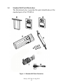
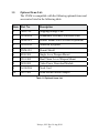
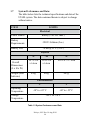
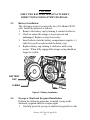
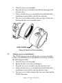
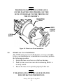
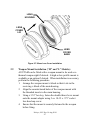
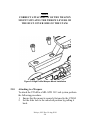
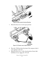
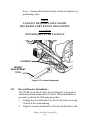
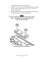
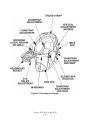
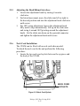
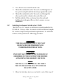
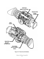
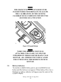
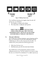
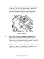
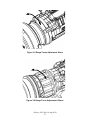
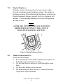
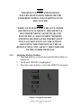
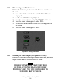
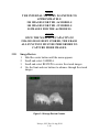
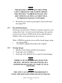
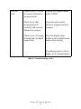
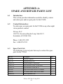
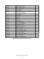
1
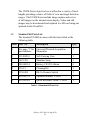
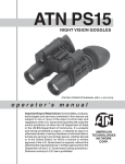
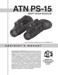
P/N 830-0027-0
OPERATOR MANUAL
UTAMTM Series
Universal Thermal Acquisition Monocular
Nivisys, LLC
15475 N. Greenway Hayden Loop
Suite B-21
Scottsdale, AZ 85260 USA
480-970-3222 (tel)
480-970-3555 (fax)
[email protected]
www.nivisys.com
Export of the commodities described herein is strictly prohibited without a valid export
license issued by the U.S. Department of State Office of Defense Trade
Controls prescribed in the International Traffic in Arms Regulations (ITAR) Title 22, Code
of Federal Regulation, Chapter 1, Subchapter M, Parts 120-130.
Inside cover intentionally left blank.
OPERATOR MANUAL
for
UTAM Series
Universal Thermal Acquisition Monocular
Part NUmber
3405-000
3400-000
3407-000
3205-000
3207-000
3210-000
3213-000
3215-000
3217-000
3220-000
3221-000
3212-000
3219-000
3222-000
3225-000
3315-000
3320-000
Model DESCRIPTION (Lens, CoRE)
PHOENIX-S (19mm, 25µ)
UTAM-16cS (19mm, 25µ)
UTAM-16iS (19mm, 25µ)
UTAM-32cS (19mm, 25µ)
UTAM-327cS (19mm, 17µ)
UTAM-32iS (19mm, 25µ)
UTAM-327iS (19mm, 17µ)
UTAM-32cM (35mm, 25µ)
UTAM-327cM (35mm, 17µ)
UTAM-32iM (35mm, 25µ)
UTAM-327iM (35mm, 17µ)
UTAM-32cL (60mm, 25µ)
UTAM-327cL (60mm, 17µ)
UTAM-32iL (60mm, 25µ)
UTAM-327iL (60mm, 17µ)
UTAM-64cM (35mm,17µ)
UTAM-64iM (35mm, 17µ)
ALL RIGHTS RESERVED
This document contains proprietary information developed by Nivisys, LLC. It has been prepared
to instruct Nivisys customers in the proper care and operation of the equipment respective to
this document. Neither receipt nor possession thereof confers any right to reproduce or use, or
disclose, in whole or in part, any such information without written authorization from
Nivisys, LLC. © 2014 Nivisys.
Nivisys, LLC Rev. 14 Aug 2014
i
This page intentionally left blank.
Nivisys, LLC Rev. 14 Aug 2014
ii
ADVISORY OVERVIEW
The following description categorizes the level of risk associated with
each cautionary statement displayed throughout the manual.
WARNING
highlights an operation or
procedure which, if not strictly
observed, could result in injury to or
death of personnel.
CAUTION
highlights an operation or
procedure which, if not strictly
observed, could result in damage to
or destruction of equipment or loss
of mission effectiveness.
NOTE
highlights an essential operation,
procedure, condition or statement.
Nivisys, LLC Rev. 14 Aug 2014
iii
This page intentionally left blank.
Nivisys, LLC Rev. 14 Aug 2014
iv
Table of Contents
Advisory Overviewiii
Table of Contentsv
List of Figuresviii
List of Tablesix
CHAPTER 1: GENERAL INFORMATION
1-1
1.1
Introduction1-1
1.2
Equipment Description1-1
1.3
Standard Kit Parts List
1-2
1.4
Standard Kit Parts Illustration
1-3
1.5
Optional Items List1-4
1.6
Optional Items Illustration
1-5
1.7
System Performance and Data
1-6
CHAPTER 2: PREPARATION FOR USE
2-1
2.1
Introduction2-1
2.2
Battery Precautions2-1
2.3
Battery Installation2-2
2.4 Eyecup and Shuttered Eyeguard Installation 2-2
2.5 Demist Shield Installation 2-3
2.6
19mm Lens Cover Installation
2-4
2.7
35mm Lens Cover Installation 2-5
2.8 60mm Lens Cover Installation 2-6
2.9 Weapon Mount Installation 2-7
2.10 Attaching the UTAM to a Weapon 2-8
2.11
Doevtail Bracket Installation
2-11
2.12 Headmount Installation and Adjustmetn
2-13
2.13
Head/Helmet Interface Installation
2-15
Nivisys, LLC Rev. 14 Aug 2014
v
Table of Contents (cont.)
CHAPTER 2: PREPARATION FOR USE (cont.)
2.14
Attachign to a Head/Helmet Mount
2.15
Adjusting the Head/Helmet Mount
2.16
Neck Cord Installation
2.17
Installing the Remote Switch to the UTAM 2.18 Attaching the Remote Switch to the Weapon 2-1
2-16
2-17
2-17
2-18
2-19
CHAPTER 3: OPERATING INSTRUCTIONS 3-1
3.1 Introduction 3-1
3.2 Operating Precautions 3-1
3.3 Controls and Indicators
3-1
3.4 Powering ON the UTAM
3-3
3.5 Battery Indicator 3-4
3.6 Thermal Calibration3-5
3.7 Range Focus Adjustment (Units with 60mm Lens) 3-6
3.8 Digital Zoom 3-8
3.9 Polarity (White-Hot/Black-Hot) 3-8
3.10 Display Brightness 3-9
3.11 Menu Activation and Use 3-9
3.12 Selecting Display Mode 3-10
3.13 Selecting the Reticle Pattern 3-11
3.14
Removing Reticle3-12
3.15
Adjusting Reticle Position
3-13
3.16 Zeroing as a Weapon Sight
3-14
3.17
Determining Installed Firmware
3.16
3.18
Enabling the Video Output (Optional VPDM)
3-16
3.19
Camera Operation3-17
3.20
Image Review3-18
Nivisys, LLC Rev. 14 Aug 2014
vi
Table of Contents (cont.)
CHAPTER 3: OPERATING INSTRUCTIONS 3-1 (cont.)
3.21
Downloading Images3-19
3.22
Erasing Images3-19
3.23
Powering OFF the UTAM Series
3-20
3.24 Use with the Remote Switch 3-20
3.25 Preparation for Storage 3-21
CHAPTER 4: MAINTENANCE INSTRUCTIONS 4-1
4.1 Introduction 4-1
4.2 Preparing for Maintenance 4-1
4.3 Cleaning the UTAM 4-1
4.4 Cleaning the Optics 4-2
4.5 Checking for Damage and Corrosion 4-2
CHAPTER 5:TROUBLESHOOTING5-1
5.1
Troubleshooting Procedures5-1
APPENDIX A: SPARE AND REPAIR PARTS LIST
A-1
A.1
IntroductionA-1
A.2
Contact InformationA-1
A.3
Spare Part ListA-1
APPENDIX B: WARRANTY INFORMATIONB-1
Nivisys, LLC Rev. 14 Aug 2014
vii
List of FIGURES
FIGURE DESCRIPTION 1-1 Standard Kit Parts Illustration 1-2 Optional Parts Illustration PAGE
1-3
1-5
2-1
Battery Installation 2-2
2-2
Eyecup Installation 2-3
2-3 Shuttered Eyeguard Installation 2-3
2-4 Demist Shield Installation 2-4
2-5
19mm Lens Cover Installation
2-5
2-6 35mm Lens Cover Installation 2-6
2-7 60mm Lens Cover Installation 2-7
2-8 High Profile Weapon Mount Installation 2-8
2-9 Slide Lock in Unlocked Position 2-9
2-10 Throw Levers in Open Position 2-9
2-11 Throw Lever Closed 2-10
2-12 Throw Lever Mount Locked 2-10
2-13 Locknut Adjustment 2-11
2-14
Dovetail Bracket Installation
2-12
2-15
Headmount Diagram2-14
2-16
Helmet/Head Interface2-15
2-17
Head/Helmet Mount Interface Installation
2-16
2-18
Attaching the UTAM to a Head/Helmet Mount
2-16
2-19
Neck Cord Eyelets2-17
2-20 Remote Switch Installation 2-19
2-21 Hook and Loop Installation 2-21
3-1 Controls and Indicators 3-2
3-2 Keypad Buttons 3-4
3-3 Battery Indicator Icons 3-5
3-4 Calibration 3-6
3-5 Range Focus Adjustment 60mm
3-7
Nivisys, LLC Rev. 14 Aug 2014
viii
List of FIGURES
FIGURE DESCRIPTION PAGE
3-6
Range Focus Adjustment 100mm
3-7
3-3 Zoom Button 3-8
3-8 Polarity Button 3-8
3-9 Display Brightness Button 3-9
3-10 Main Menu3-10
3-11
Display Sub-menu 3-10
3-12
Reticle Sub-menu3-12
3-13 Reticle Types3-12
3-14 Adjust Sub-menu3-13
3-15 Reticle Adjustment3-14
3-16 Utility Sub-menu3-16
3-17 Camera Sub-menu
3-17
3-18 Image Review Counter
3-18
3-19
Erase All Function3-20
3-20
Powering OFF the UTAM Series
3-20
3-21
Remote Switch3-21
List of Tables
TABLE DESCRIPTION PAGE
1-1 Standard Kit Parts List 1-2
1-2 Optional Items List 1-4
1-3 System Performance and Data 1-6
3-1 Controls and Indicators 3-3
3-2
Reticle Adjustment Per Click “c” Versions
3-15
3-3
Reticle Adjustment Per Click - “i” Versions
3-15
5-1 Troubleshooting 5-1
A-1 Spare and Repair Parts List A-1
Nivisys, LLC Rev. 14 Aug 2014
ix
This page intentionally left blank.
Nivisys, LLC Rev. 14 Aug 2014
x
CHAPTER 1:
GENERAL INFORMATION
1.1 Introduction:
This manual provides operation and maintenance instructions
for the UTAM. It also provides specifications and data on the
performance of the weapon sight. To ensure the safety of the
operator and the correct operation of the weapon sight it is
recommended that this manual is read carefully in its entirety
before any deployment or field application.
1.2 Equipment Description:
The UTAM Series defines what a multi-use thermal imager
should be. It is small enough to fit in a cargo pocket and
designed to be handheld. But it is also rugged enough to be
attached to a light machine gun with any standard Picatinny
rail system. The UTAM Series gives the operator enhanced
surveillance and targeting capability during night and adverse
weather conditions. User selectable reticles and digital windage
and elevation adjustments are readily available through the
onboard software and the monocular can be easily bore-sighted
to any weapon. An included remote control switch provides
increased flexibility for the user, integrating the sight and the
weapon.
The UTAM Series units are easy to operate with simple and
intuitive controls, with standard features such as polarity,
display brightness and digital zoom. The user menu provides
a selection of display modes including color or monochrome
and contrasting reticle color, enabling the user to optimize the
viewed image for the target and scene conditions.
Nivisys, LLC Rev. 14 Aug 2014
1-1
The UTAM Series objective lens is offered in a variety of focal
lengths providing a choice of fields of view and target detection
ranges. The UTAM Series include image capture and review
of still images on the internal micro-display. Video and still
images may be downloaded and captured to a SD card using our
optional Audio Visual Kit.
1.3 Standard Kit Parts List:
The standard UTAM kit comes with the items listed in the
following table.
Item
Part No.
Description
Qty.
1
See page “i” for
part numbers.
Universal Thermal Acquisition
Monocular
1
2
111-0009-0
Soft Carrying Case
1
3
1407-501
Shoulder Strap
1
4
580-0002-0
Battery, CR123 Lithium
4
5
170-12
Cleaning Kit
1
6
3250-000
RS-16, Remote Switch
1
7
830-0027-0
Operator Manual, UTAM
1
8
830-0028-0
Quick Reference Guide, UTAM
1
Table 1-1 Standard Kit Parts List
Nivisys, LLC Rev. 14 Aug 2014
1-2
1.4 Standard Kit Parts Illustration:
The illustration below is provided for quick identification of the
standard parts of the UTAM kit.
Figure 1-1 Standard Kit Parts Illustration
Nivisys, LLC Rev. 14 Aug 2014
1-3
1.5
Optional Items List:
The UTAM is compatible with the following optional items and
accessories listed in the following table.
Item
Part No.
Description
1
7B257-2F
Shipping/Storage Case
2
A3144268
Headmount Assembly with Brow Pads
3
1840010-3
Helmet Mount with Elevation Adjustment
4
A3256345
Shuttered Eyeguard
5
NVM-033
Demist Shield
6
4200-900
Single Lever Weapon Mount
7
3501-900
Dual Throw Lever Weapon Mount
8
3490-000
Video Power Download Module
9
A3144306
Neck Cord
10
1407-400
Head/Helmet Mount Adapter
Table 1-2 Optional Items List
Nivisys, LLC Rev. 14 Aug 2014
1-4
1.6
Optional Items Illustration:
The illustration is provided as a visual key to optional items that
can be used with the standard UTAM.
Figure 1-2 Optional Parts Illustration
Nivisys, LLC Rev. 14 Aug 2014
1-5
1.7
System Performance and Data:
The table below lists the technical specifications and data of the
UTAM system. The data contained herein is subject to change
without notice.
ITEM
LIMITS
Electrical
Power Source
Battery (3.0V DC max.)
Battery
Requirements
CR123 Lithium (2ea.)
Battery Life
>4 hrs @ 21°C (70°F)
Physical
Overall
Dimensions
(L x H x W)
Weight (with
batteries)
-S
-M
-L
14.7 x 6.0
x 6.6cm
15.4 x 6.0
x 6.6cm
18.0 x 6.7 x 7.4cm
430g
465g
607g
Environmental
Operating
Temperature
Storage
Temperature
“c”
“i”
-10º to +45º C
-40º to +55º C
-40°C to +70°C
Table 1-3 System Performance and Data
Nivisys, LLC Rev. 14 Aug 2014
1-6
Thermal Core
-16 (25µ)
-32 (25µ)
-32 (17µ)
-64 (17µ)
Sensor
Resolution
160 x 120
324 x 256
336 x 256
640 x 480
Pixel Pitch
25µm
25µm
17µm
17µm
Sensor
Vanadium Oxide (VOx)
Microbolometer
Uncooled
30Hz frame rate
Thermal
Sensitivity
<50mK
Spectral
Response
7 – 14 µm
Video Output
Composite, NTSC
Optical
-S
-M
-L
Objective Lens
Focal Length
19mm,
35mm
60mm
Objective Lens
F Number
f/1.25
f/1.4
f/1.25
Diopter Range
Eye Relief
+2 to -6 diopters
25mm
Nivisys, LLC Rev. 14 Aug 2014
1-7
Magnification and Field of View by Model
Model
PN
Pixel
Pitch
MAG
FOV
(H x V)
25µ
1.3
12º x 9º
25µ
1.3
12º x 9º
PHOENIX-S
3405-000
UTAM-16cS
3400-000
UTAM-16iS
3407-000
UTAM-32cS
3205-000
25µ
1.0
24º x 19º
UTAM-327cS
3207-000
17µ
1.5
16º x 13º
UTAM-32iS
3210-000
25µ
1.0
24º x 19º
UTAM-327iS
3213-000
17µ
1.0
16º x 13º
UTAM-32cM
3215-000
25µ
1.9
13º x 10º
UTAM-327cM
3217-000
17µ
2.7
9º x 7º
UTAM-32iM
3220-000
25µ
1.9
13º x 10º
UTAM-327iM
3221-000
17µ
2.7
9º x 7º
UTAM-32cL
3212-000
25µ
3.1
8º x 6º
UTAM-327cL
3219-000
17µ
4.6
5º x 4º
UTAM-32iL
3222-000
25µ
3.1
8º x 6º
UTAM-327iL
3225-000
17µ
4.6
5º x 4º
UTAM-64cM
3315-000
UTAM-64iM
3320-000
17µ
1.4
18º x 13º
Table 1-3 System Performance and Data, (cont.)
Nivisys, LLC Rev. 14 Aug 2014
1-8
CHAPTER 2:
PREPARATION FOR USE
2.1 Introduction:
This section contains instructions for installing and attaching
various components and accessories to the UTAM for operation
under normal conditions.
2.2Battery Precautions:
WARNING
Do not mix old and new Batteries.
Do not mix brands of Batteries.
do not mix disposable and
rechargeable batteries. Failure to
follow these instructions could
result in death, injury or imposition
of long-term health hazards.
Warning
Inspect batteries for bulging prior
to use. If the battery shows signs of
bulging, do not use.
Warning
DO NOT HEAT, PUNCTURE, SHORT CIRCUIT,
ATTEMPT TO RECHARGE OR OTHERWISE
TAMPER WITH THE BATTERIES. TURN
OFF the UTAM IF the BATTERY
COMPARTMENT BECOMES UNDULY HOT.
IF POSSIBLE, WAIT UNTIL THE BATTERIES
HAVE COOLED BEFORE REMOVING THEM.
Nivisys, LLC Rev. 14 Aug 2014
2-1
CAUTION
Obey the battery manufacturer’s
directions for battery disposal.
2.3Battery Installation:
The electronic circuit is powered by two (2) Lithium CR123
cells. Install the batteries as follows.
1. Remove the battery cap by turning it counter-clockwise.
2. Check to ensure the orange o-ring is present and
undamaged. Replace o-ring if necessary.
3. Insert batteries into the battery compartment, negative (-)
ends first, positive ends toward the battery cap.
4. Replace battery cap, turning it clockwise until a stop
occurs. When fully engaged the orange o-ring should no
longer be visible.
battery
cap
o-ring
Figure 2-1 Battery Installation
2.4
Eyecup or Shuttered Eyeguard Installation:
Perform the following procedure to install eyecup or the
shuttered eyeguard onto the weapon sight.
1. Carefully press the eyecup or shuttered eyeguard over the
Nivisys, LLC Rev. 14 Aug 2014
2-2
end of the eyepiece lens.
2. Rotate the eyecup into proper viewing position. Adjust for
best fit.
EYECUP
Figure 2-2 Eyecup Installation
shuttered
EYEGUARD
(optional)
Figure 2-3 Shuttered Eyeguard Installation
2.5
Demist Shield Installation (Optional):
Perform the following procedures to install the demist shield on
the eyepiece lens. This is a standard item for “S” models only.
Carefully remove the eyecup or shuttered eyeguard.
1. Carefully screw the demist shield onto the eyepiece in a
Nivisys, LLC Rev. 14 Aug 2014
2-3
clockwise direction. Be careful not to smudge the eyepiece
lens or demist shield.
2. Replace the eyecup or shuttered eyeguard.
EYEPIECE
demist
shield
Figure 2-4 Demist Shield Installation
CAUTION
If the demist shield is wiped while
wet or with wet lens tissue, the
coating will be damaged.
NOTE
If inclement operating conditions
are expected to exist (e.g. significant
temperature change and high
humidity), install demist shield to
minimize eyepiece lens fog prior to
execution of mission.
2.6
19mm Lens Cover Installation:
The UTAM units are issued with the lens covers pre-installed.
Perform the following procedures to install the lens cover on the
19mm objective lens.
Nivisys, LLC Rev. 14 Aug 2014
2-4
1. Close the lens cover assembly.
2. Press the lens cover assembly onto the lens housing of the
objective lens.
3. Gently rock the lens cover assembly back and forth while
continuing to press firmly onto the lens housing.
4. The lens cover is fully seated as the rear edges of the lens
housing and lens cover assembly meet.
Lens cover
Figure 2-5 19mm Lens Cover Installation
2.7
35mm Lens Cover Installation:
The UTAM units are issued with the lens covers pre-installed.
In the event installation or re-installation is necessary, perform
the following procedure.
1. Close the lens cover assembly.
2. Ensure the lens cover catch is facing up.
3. Press the lens cover assembly onto the objective lens.
4. Gently rock the lens cover assembly back and forth while
continuing to press firmly onto the objective lens.
5. The lens cover is fully seated as the lens cover base and the
UTAM body meet.
Nivisys, LLC Rev. 14 Aug 2014
2-5
NOTE
Proper installation of the lens
cover matches the profile of the
lens cover base to the profile of
the UTAM body.
Objective
lens
Lens
cover
catch
UTAM
BODY
Figure 2-6 35mm Lens Cover Installation
2.8
60mm Lens Cover Installation:
The UTAM units are issued with the lens covers pre-installed.
In the event installation or re-installation is necessary, perform
the following procedure.
1. Stretch the lens cover base over the lens housing.
2. Push the lens cover base onto the lens housing until it is
securely seated.
3. Ensure the lens cover operates properly before use.
note
the 60mm lens COVER can be rotated
for operator preference.
Nivisys, LLC Rev. 14 Aug 2014
2-6
LENS
HOUSING
LEns
cover
LID
LEns
cover
BASE
Figure 2-7 60mm Lens Cover Installation
2.9
Weapon Mount Installation (“M” and “L” Models):
All UTAM can be fitted with a weapon mount to be used as a
thermal weapon sight if desired. A high or low profile mount is
available as an option if desired. When installation is necessary,
perform the following procedure.
1. Arrange the weapon mount v-block so that it sits in the
receiving v-block of the main housing.
2. Align the counter-bored holes of the weapon mount with
the threaded inserts in the main housing.
3. Using a 3/32” hex key, fasten the double throw lever mount
onto the mount adapter using 2 ea. 10-32 x .375” socket
low-head cap screw.
4. Ensure that the mount is securely fastened to the weapon
before firing.
Nivisys, LLC Rev. 14 Aug 2014
2-7
note
correct attachment of the weapon
mount situates the throw levers on
the Dust Cover side of the UTAM.
Figure 2-8 High Profile Weapon Mount Installation
2.10
Attaching to a Weapon:
To attach the UTAM to a MIL-STD 1913 rail system perform
the following procedure.
1. Ensure that the mount is securely fastened to the UTAM.
2. Set the slide lock to the unlocked position by pulling it
back.
Nivisys, LLC Rev. 14 Aug 2014
2-8
Figure 2-9 Slide Lock in Unlocked Position
3. Rotate the throw levers to the open position.
OPEN
LEVER
POSITION
Figure 2-10 Throw Levers in Open Position
4. Place the UTAM on the rail system of the weapon so that it
seats squarely on the rail.
5. Rotate the throw lever to the closed position. Ensure that
both throw levers engage the 1913 rail.
Nivisys, LLC Rev. 14 Aug 2014
2-9
CLOSED
LEVER
POSITION
Figure 2-11 Throw Lever Closed
6. Secure the slide lock to the locked position by pushing it
forward.
Figure 2-12 Throw Lever Mount Locked
7. If needed, tighten the tension of the locking lever with
the provided mount adjustment tool. Turning the locknut
clockwise makes it more difficult to open or close the
Nivisys, LLC Rev. 14 Aug 2014
2-10
levers. Turning the locknut counter-clockwise makes lever
positioning easier.
NOTE
Locknut requires only slight
movement for tension adjustment.
Caution
never remove the locknut.
LOCKnut
mount
adjustment
tool
Figure 2-13 Locknut Adjustment
2.11
Dovetail Bracket Installation :
All UTAM can be fitted with a dovetail bracket to be used as
a helmet mounted monocular if desired. When installation is
necessary, perform the following procedure.
1. Arrange the dovetail bracket so that it sits in the receiving
v-block of the main housing.
2. Align the counter-bored holes of the dovetail bracket with
Nivisys, LLC Rev. 14 Aug 2014
2-11
the threaded inserts in the main housing.
3. Using a 3/32” hex key, fasten the double throw lever mount
onto the mount adapter using 2 ea. 10-32 x .375” socket
low-head cap screw.
4. Ensure that the bracket is securely fastened to the housing
before attaching to a helmet or head mount.
note
NIVISYS STRONGLY SUGGESTS THAT ONLY
THE -S models be considered for
used with helmet.
Figure 2-14 Dovetail Bracket Installation
Nivisys, LLC Rev. 14 Aug 2014
2-12
2.12
Headmount Installation and Adjustment:
CAUTION
Do not put on the headmount while
the monocular is attached.
1. Prior to donning the headmount, loosen the four ends of the
chinstrap two inches from the sliding bar buckles.
2. Snap the front and rear snaps in place.
NOTE
If the headmount is too loose,
replace the SMALL BROWPAD with
either the medium or LaRge
browpad supplied with the
headmount.
3. Grasp the neck pad and pull the harness over your head and
the neck pad down to the back of your neck.
4. Holding the chin cup in position on chin, adjust both sides
of the chinstrap until you feel light pressure against your
chin. (DO NOT TIGHTEN.)
5. Maintain the position of the chin cup and remove any slack
from the chinstrap. (DO NOT TIGHTEN.)
6. Ensure that the cross-strap is not twisted and remove slack
by adjusting the vertical adjustment at the neck pad.
7. Adjust chinstrap and vertical adjustment until the chin cup
and headband are in a comfortable but firm position.
8. Install the head/helmet mount interface.
NOTE
After installing the monocular,
minor strap adjustments may be
necessary to achieve comfort.
Nivisys, LLC Rev. 14 Aug 2014
2-13
Figure 2-15 Headmount Diagram
Nivisys, LLC Rev. 14 Aug 2014
2-14
2.13
Head/Helmet Interface Installation:
Install the headmount/helmet mount adapter onto the monocular
by following the procedure.
180° SWING
ADJUSTMENT
RELEASE
BUTTON
ADJUSTMENT
KNOB
DOVETAIL
(RECEIVING)
RELEASE
LEVER
PYRAMID
CONNECTOR
Figure 2-16 Head/Helmet Interface
1. Squeeze and hold the release button towards adjustment
knob.
2. Slide the dovetail on the bottom of the UTAM onto the
receiving dovetail on the mount interface. Make sure to
center the dovetail of the interface mount over the dovetail
of the UTAM. This will ensure that the release button can
interface correctly with the UTAM.
3. Release the release button to lock it onto the UTAM
dovetail.
4. To remove the head/helmet mount interface from the
UTAM, press and hold the release button. Slide the UTAM
from the mount interface.
Nivisys, LLC Rev. 14 Aug 2014
2-15
Figure 2-17 Head/Helmet Mount Interface Installation
2.14
Attaching to a Head or Helmet Mount:
1. Press and hold the release lever of the mount interface.
2. Slide the pyramid connector into the receiving head or
helmet mount.
3. Release the release lever to lock the mount interface into
the head/helmet mount.
4. Pull the UTAM away from the head or helmet mount to
verify that it is securely attached.
RELEASE
LEVER
Figure 2-18 Attaching the UTAM to a Head/Helmet Mount
Nivisys, LLC Rev. 14 Aug 2014
2-16
2.15
Adjusting the Head/Helmet Interface:
1. Loosen the adjustment knob by turning it counterclockwise.
2. For lateral movement, move the slider arm left or right to
the desired position and turn the adjustment knob clockwise
until secure.
3. For 180° swing adjustment, loosen the adjustment knob
fully until it stops automatically. Lift up on the slider arm
and swing it around 180°(pivoting around the adjustment
knob). Set the slider arm down on the pyramid connector
and tighten the adjustment knob until secure.
2.16
Neck Cord Installation:
The UTAM can be fitted with a neck cord when needed.
To attach the neck cord to the unit perform the following
procedure:
1. Locate the two neck cord eyelets between the eyepiece and
the body of the UTAM.
Neck COrd
Eyelets
Figure 2-19 Neck Cord Eyelets
Nivisys, LLC Rev. 14 Aug 2014
2-17
2. Tie a knot in one end of the neck cord.
3. Thread the unknotted end of the neck cord through one of
the eyelets and pull until the knot stops against the eyelet.
4. Thread the unknotted end of the neck cord through the
other eyelet and tie a knot in the end of the cord.
5. Pull the middle of the cord away from the unit until
both knots catch against the eyelets to ensure a secure
attachment.
2.17
Installing the Remote Switch to the UTAM:
The RS-16 is a 16” remote switch that is issued standard to the
UTAM kit. Nivisys offers the remote switch in different lengths
for various weapon and operational requirements. To install the
remote switch perform the following procedure:
CAUTION
The RS-16 remote switch is not
designed for immersion or
underwater operations.
CAUTION
ENSURE THAT THERE IS NO WATER, DUST
OR DEBRIS IN THE CONNECTOR BEFORE
ATTACHING THE REMOTE SWITCH.
note
the rS-16 can be installed when
the UTAM is either activated or
deactivated.
1. Move the hot shoe dust cover so that it is out of the way of
Nivisys, LLC Rev. 14 Aug 2014
2-18
the connector.
2. Align the mating connectors and push the remote switch
into the hot shoe receptacle.
3. Tighten the thumbscrews.
remote
switch
connector
hot
shoe
dust
cover
thumb
screw
Figure 2-20 Remote Switch Installation
2.18
Attaching the Remote Switch to the Weapon:
The remote switch comes with the hook and loop tape
preinstalled. When replacement is necessary perform the
following procedure.
1. Determine the best placement of the remote switch to the
weapon.
2. Starting from the label side, feed the hook and loop tape
into one of the slots in the keypad housing.
3. Fold approximately two (2) inches of the hook and loop
tape onto itself and press firm.
4. Place the keypad housing on the weapon so that its cord
travels onto the weapon heading toward the UTAM.
Nivisys, LLC Rev. 14 Aug 2014
2-19
KEYPAD HOUSING
HOok and
loop
Tape
LABEL
SIDE
Figure 2-21 Hook and Loop Installation
NOTE
ENSURE THAT THE SMOOTH SIDE FACES THE
BUTTONS OF THE KEYPAD HOUSING SO THE
HOOK AND LOOP CAN ADHERE TO ITSELF
WHEN FOLDED OVER.
5. Wrap the loose hook and loop tape around the weapon and
feed the tape through the remaining open slot in the keypad
housing.
6. Cinch tight and fold the hook and loop tape back onto itself.
7. Trim any excess.
8. Check for a secure attachment before use.
CAUTION
REMOVE SLACK IN THE CORD TO PREVENT
SNAG HAZARDS.
Nivisys, LLC Rev. 14 Aug 2014
2-20
CHAPTER 3:
OPERATIng instructions
3.1Introduction:
This chapter contains instructions for the safe operation of the
UTAM under normal circumstances and environments.
3.2
Operating Precautions:
WARNING
THE THERMAL FOCAL-PLANE ARRAY
UTILIZED WITHIN THE UTAM IS
SENSITIVE TO EXPOSURE TO EXTREMELY
HIGH LEVELS OF RADIANT FLUX. NEVER
EXPOSE THE UTAM, EITHER POWERED OR
UN-POWERED, DIRECTLY TO THE SUN OR
ANY OTHER SOURCE OF RADIANT FLUX
THAT THE HUMAN EYE CANNOT TOLERATE.
NOTE
INADVERTENT SUN DAMAGE
IS NOT CONSIDERED A DEFECT
IN MATERIAL OR WORKMANSHIP,
AND IS NOT COVERED
IN THE PRODUCT WARRANTY.
3.3Controls and Indicators:
The UTAM is designed to adjust for different users and corrects
for most differences in eyesight. The controls and indicators for
the UTAM are shown in Figure 3-1 and are described in Table
3-1.
Nivisys, LLC Rev. 14 Aug 2014
3-1
keypad/
menu control
objective
lens
cover
hot
shoe
WEAPON
MOUNT
interface
diopter
adjustment
ring
Figure 3-1 Controls and Indicators
Nivisys, LLC Rev. 14 Aug 2014
3-2
Control and
Indicators
Functions
Keypad/
Menu Control
Switches unit ON or OFF.
Activates Calibration, Polarity, Display
Brightness and Digital Zoom.
Controls Internal Menu System such as reticle
selection, azimuth adjustment and elevation
adjustment.
Battery Indicator
(not shown)
Icon located in the eyepiece display that shows
battery life of the system.
Objective Lens
Cover
Protects the objective lens from environmental
contaminants and inadvertent scratching when
not in use. Must be closed when performing a
calibration to the unit.
Diopter
Adjustment Ring
Focuses eyepiece lens. Adjust for sharpest image
of display screen.
Hot Shoe
Provides the interface between the 16c Series and
accessories such as the RS-16 (remote switch)
and the VPM (external power and video).
Weapon Mount
Interface
Interface to attach weapon mounts.
Table 3-1 Controls and Indicators
3.4
Powering ON the UTAM:
When the UTAM is powered ON, the circuit will energize and
the start up screen will appear for a few seconds in the display.
To power ON the UTAM perform the following procedure.
1. Close the objective lens cover.
2. Press and hold (approx. 2 seconds) the center and rear
buttons as indicated on the keypad bezel by “PWR.”
Nivisys, LLC Rev. 14 Aug 2014
3-3
note
the objective lens cover must be
closed while powering on to allow
the calibration of the system.
Calibration is complete within two
seconds of activation.
Figure 3-2 Keypad Buttons
note
when the remote switch is
attached, the UTAM can only be
powered on through the main UTAM
keypad. all other functions can be
executed using the remote switch
KEYPAD.
3.5Battery Indicator:
To monitor available battery power, press and hold the rear
button until the battery icon appears. When battery life is low, a
flashing low battery indicator will appear near the center of the
eyepiece display.
Nivisys, LLC Rev. 14 Aug 2014
3-4
BATTERY
CHARGE
FULL
BATTERY
CHARGE
EMPTY
Figure 3-3 Battery Power Icons
Two conditions determine the length of time the unit will
operate on a set of batteries:
1. The brightness setting on the display.
2. The temperature at which the unit operates.
NOTE
When the flashing low battery
indicator appears, the unit has
approximately 5 minutes of battery
life before automatic shutdown.
3.6
Thermal Calibration:
The UTAM Series features shutterless core technology and the
lens cover unit must be closed when calibrating the system.
Calibration gives the user the clearest picture possible. To
calibrate the system perform the following procedure.
1. Fully close the lens cover.
2. Simultaneously press the front and center buttons.
The UTAM Series will automatically perform an initial
calibration at power up. For this reason it is necessary to keep
the lens cover closed for a minimum of 2 seconds at power up.
Nivisys, LLC Rev. 14 Aug 2014
3-5
A second calibration is suggested at 30 seconds after powering
ON the unit. This allows the thermal sensor to adjust to the
surrounding temperatures. Additional calibrations may be
required as surrounding temperature changes or any time a
fixed, non-uniform shading appears on the display screen.
Figure 3-4 Calibration
3.7
Range Focus Adjustment (60mm and 100mm Lenses):
The range focus ring is used to focus the objective lens for
objects viewed at varied distances. Rotate the range focus ring
counter-clockwise for distant objects up to infinity. Rotate the
range focus ring clockwise for close objects.
The 60mm lens is indicated by an “L” in the model name and
can focus to 2 meters. The 100mm lens is indicated by an “E”
in the model name and can focus to 10 meters.
Nivisys, LLC Rev. 14 Aug 2014
3-6
Figure 3-5 Range Focus Adjustment 60mm
Figure 3-6 Range Focus Adjustment 100mm
Nivisys, LLC Rev. 14 Aug 2014
3-7
3.8
Digital Zoom:
Press the Zoom button to cycle through the electronic zoom
presets.
Figure 3-7 Zoom Button
3.9
Polarity (White-Hot/Black-Hot):
The UTAM Polarity button determines one of two viewing
modes to identify environmental temperature differences:
HOT temperatures are seen as WHITE on the screen or
HOT temperatures are seen as BLACK on the screen.
Press the Polarity button to toggle between the viewing modes.
Figure 3-8 Polarity Button
Nivisys, LLC Rev. 14 Aug 2014
3-8
3.10
Display Brightness:
When the system is first turned on, the unit activates whitehot with a midrange display brightness setting. The unit has 6
brightness settings. When adjusting the brightness, each time the
Display Brightness button is pressed, the level of intensity will
increase. A corresponding brightness level icon will appear in
the field of view.
note
After the unit reaches its maximum
brightness setting it will cycle
back to its lowest setting.
Figure 3-9 Display Brightness Button
3.11
Menu Activation and Use:
To activate Menu Mode:
1. Press and hold the center button until the menu appears on
the display (approximately 2 seconds).
2. Use the front and rear buttons to scroll through the menu
items.
3. Use the center button to select an item.
4. The menu mode will time out after 7 seconds of non-use,
except in the Adjust sub-menu.
Nivisys, LLC Rev. 14 Aug 2014
3-9
Figure 3-10 Main Menu
3.12
Selecting Display Mode:
1. Push and hold the center button until the Main Menu is
displayed.
2. Press the center button to select the DISPLAY sub-menu.
Figure 3-11 Display Sub-menu
The 6 display modes to choose from are:
•
ALERT mode shows a Monochrome image with the hot
Nivisys, LLC Rev. 14 Aug 2014
3-10
spots in orange and red.
MONO mode shows a Monochrome image.
COLOR 1 mode shows hot as orange and cold as purple.
COLOR 2 mode shows gradients of brown and green with
hot temperatures shown in white.
•
COLOR 3 mode shows gradients of white, yellows and
orange with hotter temperatures in white.
•
COLOR 4 is a full color spectrum with hotter temperatures
in reds and orange and cooler temperatures in blue and
purples.
Note:
When any one of the COLOR viewing
modes is active, the pressing center
button will cycle to the next
COLOR mode.
•
•
•
3.13
Selecting a Reticle Pattern:
When the UTAM is used as a stand alone thermal weapon sight,
an internal reticle is available. To choose a specific reticle
perform the following:
NOTE
UPON START UP, the Unit will DISPLAY
THE LAST RETICLE SELECTED BY THE
USER PRIOR TO SHUTDOWN OR BATTERY
REMOVAL.
1. Push and hold the center button until the Main Menu is
displayed.
2. Scroll until RETICLE is highlighted.
3. Press the center button to select the RETICLE sub-menu.
Nivisys, LLC Rev. 14 Aug 2014
3-11
Figure 3-12 Reticle Sub-menu
4. Scroll until desired reticle appears in display.
5. Press the center button to select the reticle desired.
6. Press the center button to exit menu.
Figure 3-13 Reticle Types
NOTE
Reticle WILL AUTOMATICALLY
CHANGE BLACK/WHITE DEPENDING ON
BACKGROUND TARGET TO GIVE BEST
CONTRAST.
3.14
Removing Reticle:
To remove the reticle from the display screen perform the
following:
1. Select OFF under the Reticle sub-menu.
Nivisys, LLC Rev. 14 Aug 2014
3-12
NOTE
The reticle type and position
will be maintained through the
powering down and starting up of
the system.
NOTE
When AZ is selected, the ACCU-ZOOM
DOT reticle is shown. This reticle
has independent Azimuth (H) and
Elevation (V) adjustment memory
and will be displayed wherever it
was last moved to on the screen.
Adjusting the position of the AZ
reticle will not affect the position
of the other reticles.
3.15
Adjusting Reticle Position:
1. Push and hold the center button until the Main Menu is
displayed.
2. Scroll until ADJUST is highlighted.
3. Press the center button to select the ADJUST sub-menu.
Figure 3-14 Adjust Sub-menu
Nivisys, LLC Rev. 14 Aug 2014
3-13
4. Adjust the reticle horizontally when the H is highlighted by
using the front and rear buttons.
Figure 3-15 Reticle Adjustment
5. Press the center button when the desired position is reached.
6. Adjust the reticle vertically when the V is highlighted by
using the front and rear buttons.
7. Select EXIT.
NOTE
Each button push moves the reticle
one increment. PRESS and HOLD for
FASTER adjustment.
3.16Zeroing as a Weapon Sight:
To zero the UTAM Series, perform the following:
1. Fix a thermal target at 100 meters distance. Ensure a
sufficient thermal contrast is viewed through the UTAM
Series before continuing.
2. Ensure that the weapon mount is securely fastened to the
UTAM Series so there is no movement.
3. Securely fasten the UTAM Series to the weapon so there is
no movement.
Nivisys, LLC Rev. 14 Aug 2014
3-14
4.
5.
6.
7.
8.
9.
10.
11.
12.
Power ON the UTAM Series.
Set the Digital Zoom at 2X.
Select a reticle type.
Adjust the brightness of the display to provide a good
contrast between the target and reticle image.
Adjust the diopter ring as necessary to ensure an in-focus
image of the reticle.
Use the center of the reticle to aim the weapon at the target
and fire 3-5 rounds.
After clearing the weapon, visually check the center of the
shot grouping on the target.
Find your UTAM model in the charts below. Each button
press will move the Point of Impact a specific incremental
distance. The data below is calculated for a target placed
at 100m.
Make reticle adjustments as necessary according to the
table below.
“c” Version Reticle Adjustment Per Click (at 100 meters)
16cM
32cM
327cM
32cL
327cL
32cE
327cE
64cM
64cL
1.8cm
3.6cm
2.6cm
2.1cm
1.5cm
1.3cm
0.9cm
4.9cm
2.8cm
Table 3-2 Reticle Adjustment Per Click - “c” versions
“i” Version Reticle Adjustment Per Click (at 100 meters)
16iM
32iM
327iM
32iL
327iL
32iE
327iE
64iM
64iL
1.5cm
3.1cm
2.1cm
1.8cm
1.3cm
1.1cm
0.8cm
3.9cm
2.3cm
Table 3-3 Reticle Adjustment Per Click - “i” versions
13. Fire and adjust the reticles until the center of the shot
grouping and the reticle are coincident.
Nivisys, LLC Rev. 14 Aug 2014
3-15
3.17
Determining Installed Firmware:
Perform the following to determine the firmware installed on
the unit:
1. Push and hold the center button until the Main Menu is
displayed.
2. Scroll until UTILITY is highlighted.
3. Press the center button to enter the UTILITY sub-menu.
4. Press the center button again to select INFO.
5. At this point the information about the system appears on
the screen.
6. Press the center button again to EXIT.
Figure 3-16 Utility Sub-menu
3.18
Enabling the Video Output (for Optional VPDM):
In order to utilize the video export feature of the unit, the video
output feature must be selected from the menu.
NOTE
IT is recommended that the video
out selection remains in the off
position when not in use in order to
maximize battery life.
Nivisys, LLC Rev. 14 Aug 2014
3-16
1. Push and hold the center button until the Main Menu is
displayed.
2. Scroll until UTILITY is highlighted
3. Press the center button to select the UTILITY sub-menu.
4. Scroll until VIDEO is highlighted, then press center button
to select.
5. Scroll to choose ON or OFF.
6. Press the rear button to EXIT the video enable.
7. Press the center button twice to EXIT the menu system.
3.19Camera Operation
1. Hold the center button until the menu appears.
2. Scroll and select CAMERA.
3. Select CAPTURE to enter the camera mode.
4. Press the center button to take a picture and advance the
counter located in the upper left corner of the screen.
5. Exit the Camera mode by holding down the center button
and selecting CAPTURE or powering down the unit.
Figure 3-17 Camera Sub-menu
Nivisys, LLC Rev. 14 Aug 2014
3-17
Note
THe internal memory is limited to
approximately:
250 images for the -16 models
100 images for the -32 models
50 images for the -64 models
NOTE
once the maximum capacity of
images have been stored, the erase
all function must be performed to
capture more images.
3.20
Image Review
1. Hold the center button until the menu appears.
2. Scroll and select CAMERA.
3. Scroll and select REVIEW to review the stored images.
4. Use the front and rear buttons to advance through the stored
images.
Figure 3-18 Image Review Counter
Nivisys, LLC Rev. 14 Aug 2014
3-18
NOTE
THe Review counter in the upper
left corner of the screen shows
the specific number of image you
are viewing as well as the total
number of images captured.
5. Exit the Review mode by pressing the center button and
selecting EXIT.
3.21
Downloading Images
Still images stored on the UTAM are currently exported via an
analog video feed. In order to download images, the operator
must have the Nivisys VPDM (Video Power and Download
Module). This can be purchased as an accessory.
With a VPDM the operator can record the stored images using:
•
an external DVR
•
or computer equipped for analog video capture
3.22
Erasing Images
1. Hold the center button until the menu appears.
2. Scroll and select CAMERA.
3. Scroll and select ERASE ALL to erase the stored images.
NOTE
There is no way to erase selected
images. ERASING IMAGES ERASES ALL
stored IMAGES AND CAN TAKE UP TO 30
seconds.
NOTE
The unit can not be powered down
using the keypad while erasing images.
Nivisys, LLC Rev. 14 Aug 2014
3-19
Figure 3-19 Erase All Function
3.23
Powering OFF the UTAM Series:
To power OFF the system, perform the following:
1. Simultaneously press the center and rear buttons. Visually
check that the unit is OFF by looking through the eyepiece.
Figure 3-20 Powering OFF the UTAM Series
3.24
Use with the RS-16 Remote Switch:
The UTAM Series may be used with the supplied remote switch.
When attached, all keypad functions of the UTAM Series,
except for powering ON, can be executed using the remote
switch.
Nivisys, LLC Rev. 14 Aug 2014
3-20
Figure 3-21 Remote Switch
3.25
Preparation for Storage:
1. Remove batteries from the UTAM Series.
2. Inspect the battery housing for corrosion or moisture. Clean
and dry if necessary.
3. Replace the battery cap.
4. Remove the demist shield if installed.
5. Install objective lens cover.
NOTE
Prior to placing UTAM Series into
carrying case, ensure UTAM Series
and case are free of dirt, dust, and
moisture.
6. Place the UTAM Series, accessories and cleaning supplies
back into their storage/carrying cases. It is best to place
the items in their original locations to prevent any possible
damage to the unit and/or accessories.
7. Return to storage area.
Nivisys, LLC Rev. 14 Aug 2014
3-21
This page intentionally left blank.
Nivisys, LLC Rev. 14 Aug 2014
3-22
CHAPTER 4:
Maintenance instructions
4.1Introduction:
The UTAM is designed to be used in diverse environments and
rugged conditions. It is recommended that regular and simple
maintenance is performed for optimal system performance.
CAUTION
This weapon sight is a precision
electro-opticalinstrumentand must
be handled carefully.
Do not scratch the external lens
surfaces or touch them with your
fingers.
Wiping demist shield with lens TISSUE
while wet or with wet lens TISSUE can
damage the coating.
4.2
Preparing for Maintenance:
Before performing any maintenance or cleaning of the system,
remove all power sources from the UTAM including batteries
and/or external power supplies.
4.3Cleaning the UTAM:
When necessary, use a moistened clean cloth to wipe the outside
of the unit, EXCEPT FOR THE OPTICAL SURFACES. Be
sure to wipe away excess dirt and dust that may restrict the
performance or damage moving and mating parts. If needed,
the use of a very diluted detergent solution is permissible. Dry
Table A-1 Spare and Repair Parts List
Nivisys, LLC Rev. 14 Aug 2014
4-1
with a soft clean cloth, or allow unit to air-dry before storing it.
4.4Cleaning the Optics:
When cleaning of the lens is required, first blow any loose
dirt or grit away from the surface of the lens. EXCEPT FOR
THE DEMIST SHIELD, use the supplied lens tissue lightly
moistened with water or lens cleaning fluid to lightly wipe the
optical surfaces, using a circular motion. Discard each lens
tissue after one use to avoid transferring grit or foreign matter
onto the lens surfaces. If the lens remains dirty, use a cotton
swab lightly moistened with lens cleaning fluid to remove the
foreign matter from the lens. Dry with a clean unused lens
tissue.
4.5Checking for Damage and Corrosion:
As a general guideline, conduct an inspection of the
UTAM, accessories, and the case after every use. Look for
heavy wear and cracks in rubber or plastic. Inspect for moisture
or corrosion in the battery compartment. Check for scratches,
condensation and foreign matter on optical surfaces. Report
missing or damaged items, for replacement.
Nivisys, LLC Rev. 14 Aug 2014
4-2
CHAPTER 5:
TROUBLESHOOTING
5.1
Troubleshooting Procedures:
Table 5-1 lists common malfunctions that may occur with the
equipment. Perform the tests, inspections and corrective actions
in the order they appear in the table.
This table cannot list all the malfunctions that may occur, all
the tests and inspections needed to find the fault, or all the
corrective actions needed to correct the fault. If the equipment
malfunction is not listed or actions listed do not correct the fault,
notify your maintainer.
Malfunction
Test or Inspection
Corrective Action
Unit fails to
power ON.
Visual.
Power OFF the system and
then ON.
Check for defective,
missing or improperly
installed battery.
Replace battery or install
correctly.
Tighten battery cap until the
orange o-ring is no longer
visible.
If UTAM still fails to power
ON, refer to higher level of
maintenance.
Table 5-1 Troubleshooting
Nivisys, LLC Rev. 14 Aug 2014
5-1
Flickering
Image on
firing.
Check for loose battery
cap that may cause the
battery to lose contact
during weapon fire.
Tighten battery cap until the
orange o-ring is no longer
visible.
No display
in eyepiece.
Visual check to see if
lens cover is still on.
Flip lens cover open.
Check to see if
shuttered eyeguard is
installed.
Press eye firmly against
shuttered eyeguard.
Check focus of the
eyepiece lens.
Refocus.
Check for fogging or
dirt on objective lens
or eyepiece lens.
Clean optics.
Check eye relief
distance.
Readjust for proper eye
relief distance.
Check eyecup for
resiliency.
If eyecup is defective,
refer to higher level of
maintenance.
Poor image
quality.
Light visible
around
eyecup.
Table 5-1 Troubleshooting, (cont.)
Nivisys, LLC Rev. 14 Aug 2014
5-2
Remote
Switch
keypad not
working.
Check to ensure hot
shoe connector is
completely installed
into unit.
Firmly push connector
into mating connector on
UTAM unit and tighten
thumbscrew.
Check to ensure
connectors are free
from debris, dirt and
corrosion.
Clean connectors.
If remote switch keypad is
still not working, refer to
higher level of maintenance.
Optics hard
to turn or
grinding.
Check for dirt or debris Clean with a soft dry cloth.
on traveling eyepiece
cell.
Check to see if the
diopter adjustment is
bent or broken.
If damaged, refer to higher
level of maintenance.
Table 5-1 Troubleshooting, (cont.)
Nivisys, LLC Rev. 14 Aug 2014
5-3
Will not
zero.
Check to see if UTAM
is securely fastened to
weapon mount.
Tighten the weapon mount
to the UTAM.
Check to see that
weapon mount is
correctly and securely
fastened to weapon.
Correctly and securely
fasten to weapon mount to
weapon.
Check to see if zeroing
is being done in digital
zoom mode.
Press the digital zoom
button to enter digital zoom
mode when zeroing.
If problem persists, refer to
higher level of maintenance.
Table 5-1 Troubleshooting, (cont.)
Nivisys, LLC Rev. 14 Aug 2014
5-4
APPENDIX A:
SPARE AND REPAIR PARTS LIST
A.1Introduction:
This section provides information needed to identify, contact
and order spare and/or repair parts for the UTAM.
A.2Contact Information:
To order spare or repair parts for the UTAM or any other night
vision products contact:
Nivisys, LLC
15475 N. Greenway Hayden Loop, Suite B-21
Scottsdale, AZ 85260 USA
Phone: 1-480-970-3222
Fax: 1-480-970-3555
A.3
Spare Parts List:
The following is a list of parts that may be ordered for spare
parts for the UTAM.
Part No.
Description
Qty.
A3256345
Shuttered Eyeguard
1
7B257-2F
Shipping/Storage Case
1
830-0071-0
Operator Manual, UTAM Series
1
830-0072-0
Quick Reference Guide, UTAM Series
1
830-0057-0
Quick Reference Guide, RS-16
1
3501-900
High Profile Double Throw Lever Mount
1
3500-900
Low Profile Double Throw Lever Mount
1
790-0015-0
Mount Adjustment Tool
1
Nivisys, LLC Rev. 14 Aug 2014
A-1
310-0024-0
Mount Adapter, V-Block
1
3255-000
RS-16 (Remote Switch)
1
1407-500
Soft Carrying Case
1
1407-501
Shoulder Strap
1
580-0002-0
Battery, CR123 Lithium
(2ea. required for operation)
1
NVM-033
Demist Shield
1
170-12
Cleaning Kit
1
4500-202
Eyecup
1
A3144306
Neck Cord
1
A3144315
Purge Screw
1
A3144316
Purge Screw O-Ring
1
3200-114
Dust Cover Retaining Pin
1
3200-112
Hot Shoe Dust Cover
1
640-0003-0
Hook and Loop Tape (16 in)
1
220-0013-0
60mm Lens Cover
1
A3187392
Soft Carrying Case - Green
1
4200-800
Lens Cap Assembly (35mm)
1
3200-620
Battery Cap Assembly
1
111-0009-0
Soft Carrying Case - Black
1
220-00013-0
Lens Cover (60mm)
1
310-0015-0
Eyepiece Eyecup Retainer
1
Table A-1 Spare and Repair Parts List, (cont.)
Nivisys, LLC Rev. 14 Aug 2014
A-2
APPENDIX B:
WARRANTY INFORMATION
Equipment Warranties And Remedy:
Seller warrants that each newly manufactured item sold hereunder
and such portion of a repaired/refurbished item as has been repaired
or replaced by Seller under this warranty, shall be free from defects
in material or workmanship at the time of shipment and shall perform
during the warranty period in accordance with the specifications
incorporated herein. Should any failure to conform to these warranties
be discovered and brought to Seller’s attention during the warranty
period and be substantiated by examination at Seller’s factory or by
authorized field personnel, then at its own cost, Seller shall correct
such failure by, at Seller’s option, repair or replacement of the nonconforming item or portion thereof, or return the unit purchase price of
the non-conforming item or component. Buyer agrees that this remedy
shall be its sole and exclusive remedy against Seller and that no other
remedy shall be available or pursued by Buyer against Seller. In no
event shall the Seller be liable for any cost or expense in excess of those
described in this paragraph and expressly excluding any liability or
damages for special, incidental or consequential damages.
The warranty period for newly-manufactured items shall extend 24
months from the date of shipment by Seller unless a different warranty
period is agreed in writing to by Seller. The warranty period for repaired/
refurbished electronic components shall extend for the unexpired
warranty period or 90 days, whichever is longer, of the item repaired or
replaced.
This warranty shall not extend to any item that upon examination by
Seller is found to have been subject to:
A. Mishandling, misuse, negligence or accident.
Nivisys, LLC Rev. 14 Aug 2014
B-1
B. Installation, operation or maintenance that either was not in
accordance with Seller’s specifications and instructions, or
otherwise improper.
C. Tampering, as evidenced, for example, by broken seals,
damaged packaging containers, etc.
D. Repair or alteration by anyone other than Seller without
Seller’s express advance written approval.
Failure to promptly notify Seller in writing upon discovery of any nonconforming item during the warranty period shall void the warranty as
to such item. Buyer shall describe any such non-conformity in detail,
expressing its position as to return of any article under the remedy
provided herein. No returns shall be accepted without prior approval by
Seller.
Return Material Authorization Number (RMA#):
Warranty and non-warranty items returned to Nivisys for repair or
replacement require a RMA#. Email [email protected], call
1-480-970-3222 or fax 1-480-970-3555 with a serial number and detailed
information to obtain a RMA#.
THIS WARRANTY IS EXCLUSIVE AND IN
LIEU OF ANY OTHER WARRANTY, EITHER
EXPRESSED OR IMPLIED, INCLUDING
WARRANTIES OF MERCHANTABILITY OR
FITNESS FOR A PARTICULAR PURPOSE.
Nivisys, LLC Rev. 14 Aug 2014
B-2
Inside cover intentionally left blank.
Nivisys, LLC Rev. 14 Aug 2014
B-3
Nivisys, LLC
15475 N. Greenway Hayden Loop, Suite 105
Tempe, Arizona 85281
USA
nivisys.com