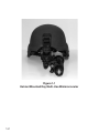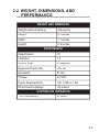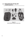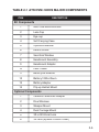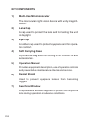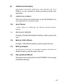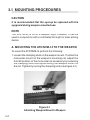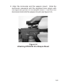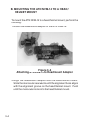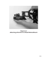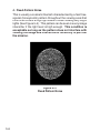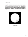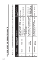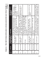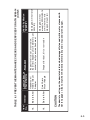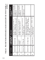
1
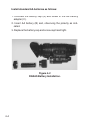
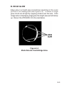
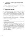
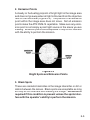
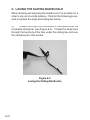
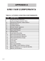
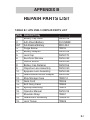
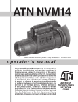
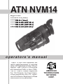
ATN NVM14
Mfg’s P/Ns:
ATN NVM-14-2 (Gen2)
ATN NVM-14-3 (Gen3)
ATN NVM-14-XD4 (DEP XD-4)
ATN NVM-14-XR5 (DEP XR-5)
ATN NVM-14-XXX (XXX XX-X)
o p e r a t o r s ’s m a n u a l
Export of night vision equipment and
optical sighting equipment is controlled
by the U.S. Department of State, Office of
Defense Trade Controls in accordance
with International Traffic in Arms (ITAR),
Title 22, Code of Federal Regulations
Part 120-130and/or the Export Administration Regulations (EAR) U.S. Department of Commerce. Illegal export of these
commodities is strictly prohibited.
AMERICAN
TECHNOLOGIES
NETWORK
CORP.
Manual (NVM14-002) Revision 3 - July 2004
The information in this manual furnished for information use only, is subject to
change without notice, is not to be construed as a commitment by ATN Corp.
ATN Corp. assumes no responsibility or liability for any errors or inaccuracies
that may appear in this book.
© 2004 ATN Corp. All right reserved.
SAFETY SUMMARY
CAUTIONS
• The ATN NVM-14 is a precision optical instrument and must be
handled carefully at all times to prevent damage.
• Do not scratch the external lens surfaces or touch them with
your fingers.
• Wiping demisting shield with lens paper while wet or with wet
lens paper can damage the coating.
• To protect the image intensifier, keep the lens cap on the objective lens when the monocular is not in use or when checked out
in daylight conditions.
• The IR illuminator is a light that is invisible to the unaided eye
for use during conditions of extreme darkness. However, the
light from the illuminator can be detected by the enemy when
using night vision devices.
a
NOTES
• When utilizing the ATN NVM-14 for driving purposes, the goggles may not be used in the hand-held mode. The goggles must
be worn in the head- or helmet-mounted position.
• At operating temperatures below –20°C (-4°F), alkaline batteries are not recommended, as operating life will be severely
reduced. Lithium-iron disulfide 1.5V AA batteries or equivalent
should be used below –20°C (-4°F).
• The purpose of the illuminator is for viewing at close distance
up to 3 meters when additional illumination is needed.
b
EQUIPMENT LIMITATIONS
To avoid physical and equipment damage when using the ATN
NVM-14, carefully read and understand the following safety precautions.
• The equipment requires some night light (moonlight, starlight,
etc.) to operate. The level of performance depends upon the level
of light.
• Night light is reduced by passing cloud cover, while operating
under trees, in building shadows, etc.
• The equipment is less effective viewing into shadows and other
darkened areas.
• The equipment is less effective through rain, fog, sleet, snow or
smoke.
• The equipment will not “see” through dense smoke.
• Adjust vehicular speed to prevent overdriving the range of view
when conditions of possible reduction or loss of vision exist.
c
TABLE OF CONTENTS
Section
i
Title
Page
Safety Summary
a
Table Of Contents
List of Figures
List of Tables
How To Use This Manual
i
ii
iii
iv
Section I
II
III
IV
V
VI
General Information
Equipment Description
Mounting Procedures
Operating Procedures
Operational Defects
Maintenance
1-1
2-1
3-1
4-1
5-1
6-1
Appendix A
End Item Components
A-1
Appendix B
Repair Parts List
B-1
Index
IND-1
For Technical Information
INFO-1
LIST OF FIGURES
Figure
Title
1-1
Helmet Mounted Multi-Use
Minimonocular
1-2
2-1
ATN NVM-14DNS Major Components
2-4
3-1
3-2
3-3
Attaching Weapon Mount to Weapon
Attaching MUM to Weapon Mount
Attaching the MUM to Headmount
Adapter
Attaching the MUM to Head/Helmet
Mount
3-2
3-3
3-4
4-1
4-2
4-3
DL123 Battery Installation
AA Battery Installation
Mechanical Functions
4-3
4-4
4-5
5-1
5-2
5-3
5-4
5-5
Shading
Edge Glow
Bright Spots and Emission Points
Fixed Pattern Noise
Chicken Wire
5-2
5-3
5-5
5-6
5-7
6-1
6-2
Neckpad Reinstallation
Lacing the Sliding Bar Buckle
6-11
6-12
3-4
Page
3-5
ii
LIST OF TABLES
Table
iii
Title
Page
2-1
ATN NVM-14DNS Major Components
2-5
4-1
Battery Life
4-2
6-1
Preventive Maintenance Checks and
Service for the ATN NVM-14
6-2
6-2
Operator Troubleshooting for the ATN
NVM-14
6-8
A-1
ATN NVM-14 End Item Components
A-1
B-1
ATN NVM-14 Repair Parts List
B-1
HOW TO USE THIS MANUAL
USAGE
You must familiarize yourself with the entire manual before
operating the equipment. Read the complete maintenance task
before performing maintenance and follow all WARNINGS,
CAUTIONS, and NOTES.
MANUAL OVERVIEW
The manual contains sections for Operating and Maintaining
the Day Night SightMulti-Use Minimonocular NVG.
Components of End Item are in Appendix A.
Repair Parts List is in Appendix B.
iv
v
SECTION I
GENERAL INFORMATION
1-1
Figure 1-1
Helmet Mounted Day Multi-Use Minimonocular
1-2
1-1 GENERAL INFORMATION
A. TYPE OF MANUAL
Operator (Including Repair Parts List).
B. MODEL NUMBER AND EQUIPMENT NAME
ATN NVM-14 – Multi-Use Minimonocular
C. SUPPLIER
American Technologies Network Corp.
20 South Linden Ave. Unit 1B,
South San Francisco, CA 940801
D. PURPOSE OF EQUIPMENT
To provide the soldier with the ability to observe at night
under moonlight and starlight conditions. The ATN NVM-14
can be handheld, head mounted, helmet mounted or weapon
mounted to enable walking, driving, weapon firing, shortrange surveillance, map reading, vehicle maintenance, and
administering first aid. The unit allows for horizontal and vertical adjustments when head or helmet mounted and is also
equipped with an infrared light-emitting source.
1-3
1-2 WARRANTY INFORMATION
This item shall conform to design, manufacturing, and performance requirements and be free from defects in material
and workmanship for a period of two (2) years from the date of
acceptance. If item is defective, notify your Service Command
Technical point of contact.
1-3 TECHNICAL INFORMATION
For technical information contact ATN Corp. directly at
(650) 875-0130, or [email protected] your Service Command point of contact.
1-4 LIST OF ABBREVIATIONS
1-4
BAT
- Battery
Illum
- Illuminator
IR
- Infrared
mm
- Millimeters
NVG’s
- Night Vision Goggles
SECTION II
EQUIPMENT DESCRIPTION
2-1
2.1 SYSTEM DESCRIPTION
The ATN NVM-14 is a hand-held, head-mounted, helmetmounted, or weapon-mounted night vision system that enables
walking, driving, weapon firing, short-range surveillance, map
reading, vehicle maintenance, and administering first aid in both
moonlight and starlight. Each unit allows for vertical adjustment
(by using head straps), fore-and-aft adjustment, objective lens
focus, and eyepiece focus. The device is also equipped with an
infrared light-emitting source.
2-2
2.2 WEIGHT, DIMENSIONS, AND
PERFORMANCE
WEIGHT AND DIMENSION
Weight (without battery)
255 grams
Length
4.1 inches
Width
1.7 inches
Heightt
2.5 inches
PERFOMANCE
Magnification
1X
f-Number
1.2
Field of View
40 degrees
Eyepiece Diopter Adj.
-4 to +6
Eye Relief
27 mm
Voltage
3.0 VDC
Power Requirements
1 DL 123A or 1 AA
IR Illumination Range
-20 meters
CONTINUOUS OPERATION
1 DL123A battery
40 hours
2-3
2.3 DESCRIPTION OF MAJOR
COMPONENTS
9
5
10
14
6
7
12
11
8
13
4
2
3
1
Figure 2-1
DNS ATN NVM-14 Major Components.
2-4
TABLE 2-1 ATN NVM-14DNS MAJOR COMPONENTS
ITEM
DESCRIPTION
Kit Components
1
Multi-Use Minimonocular
2
Lens Cap
3
Eye-cup
4
Soft Carrying Case
5
Operators Manual
6
Demist Shield
7
Sacrificial Window
8
Headmount Assembly
9
Headmount Adapter
10
Lens Tissue
11
Battery AA Alkaline
12
Battery 123A Lithium
13
Battery Adapter
14
Flip-up Helmet Mount
Optional Components
1
Camera/Camcorder Adapter
2
Dive Windows
3
Weapon Mount
4
Dual Carriage Mount
5
3X or 5X Afocal Lens
6
3X Lens (Special Custom Order)
2-5
KIT COMPONENTS
1)
Multi-Use Minimonocular
The monocular night vision device with unity magnification.
2)
Lens Cap
A cap used to protect the lens and for testing the unit
in daylight.
3)
Eye-cup
A rubber cup used to protect eyepiece and for operator comfort.
4)
Soft Carrying Case
A protective bag used for storing of ATN NVM-14 and
accessories.
5)
Operators Manual
Provides equipment description, use of operator controls
and preventative maintenance checks and service.
6)
Demist Shield
Used to prevent eyepiece lenses from becoming
fogged.
7)
Sacrificial Window
A replaceable window supplied to protect the objective
lens during operation in adverse conditions.
2-6
8)
Headmount Assembly
Adjustable universal assembly that secures the ATN
NVM-14 to the operator’s head providing hands free
operation.
9)
Headmount Adapter
This item allows the attachment of the ATN NVM-14 to
the headmount or helmet mount.
10)
Lens Tissue
Tissue used for cleaning the lenses during maintenance.
11)
Battery AA Alkaline
A single, standard AA alkaline battery used to power the
unit.
12)
Battery 123A Lithium
A single, 123A lithium battery used to power the unit.
13)
Battery Adapter
Allows the ATN NVM-14 to accept a single, standard AA
alkaline battery used to power the unit.
14)
Flip-up Helmet Mount
Provides mount interface for the ATN NVM-14 to a range
of ballistic helmets.
2-7
OPTIONAL COMPONENTS
1)
Camera/Camcorder Adapter
This adapter attaches to the ATN NVM-14 eyepiece
for collection of imagery from the ATN NVM-14.
2)
Dive Window
A window that attaches prior to submersing the
ATN NVM-14 for diving operations.
3)
Weapon Mount
Small arms adapter that allows the ATN NVM-14 to
be mounted on a weapon.
4)
Dual Carriage Mount
Adapter that allows the ATN NVM-14 to be attached
to in a binocular configuration
5)
3X or 5X Afocal Lens
Attaches to the ATN NVM-14 for enhanced range
performance
6)
3X Lens (Special Custom Order)
Attaches to the ATN NVM-14 for enhanced range
performance
2-8
SECTION III
MOUNTING PROCEDURES
3-1
3.1 MOUNTING PROCEDURES
CAUTION
It is recommended that the eyecup be replaced with the
eyeguard during weapon-mounted use.
NOTE
The ATN NVM-14 is not a weapon sight, however, it can be
used in conjunction with a collimated dot sight or laser aiming
device.
A. MOUNTING THE ATN NVM-14 TO THE WEAPON
To mount the ATN NVM-14 perform the following:
1.Loosen the clamping knob on the weapon mount. Position the
monocular mount on the weapon’s mounting rail, adjust the
fore/aft position of the monocular as necessary by loosening
the clamping knob and repositioning the weapon mount on
the rail. Tighten by turning the clamping knob (see figure 3-1).
Figure 3-1
Attaching Weapon Mount to Weapon
3-2
2. Align the monocular and the weapon mount. Slide the
monocular rearwards until the alignment boss aligns with
the alignment groove on the weapon mount. Push until the
monocular locks into the weapon mount (see figure 3-2).
Figure 3-2
Attaching ATN NVM-14 to Weapon Mount
3-3
B. MOUNTING THE ATN NVM-14 TO A HEAD/
HELMET MOUNT
To mount the ATN NVM-14 to a head/helmet mount, perform the
following:
1.Attach the headmount adapter to the ATN NVM-14.
Figure 3-3
Attaching ATN NVM-14 to Headmount Adapter
2.Align the headmount adapter and the head/helmet mount.
Slide the monocular rearwards until the alignment boss aligns
with the alignment groove on the head/helmet mount. Push
until the monocular locks into the head/helmet mount.
3-4
Figure 3-4
Attaching ATN NVM-14 to Head/Helmet Mount
3-5
3-6
SECTION IIIV
OPERATING PROCEDURES
4-1
4.1 OPERATING INSTRUCTIONS
A. BATTERY INSTALLATION
CAUTION
To protect the image intensifier, keep the lens cap on the
objective lens when the monocular is not in use or when
checked out in daylight conditions.
NOTE
At operating temperatures below –20°C (-4°F), alkaline batteries are not recommended, as operating life will be severely
reduced. Lithium-iron disulfide 1.5V A A batteries or equivalent
should be used below –20°C (-4°F).
Table 4-1 Battery Life
Estimated Battery Life
Bettery Type
Usage
DL123A
>40 Hours
Standard AA
>20 Hours
The ATN NVM-14 operates with one DL 123 battery or one AA
battery when using the AA battery adapter.
4-2
Install DL 123 batteries as follows:
1. Unscrew the battery cap (A) and insert the battery (B),
observing the polarity as indicated.
2. Replace the battery cap (A) and screw cap hand tight.
Figure 4-1
DL123 Battery Installation
4-3
Install standard AA batteries as follows:
1. Unscrew the battery cap (A) and screw in the AA battery
adapter (C).
2. Insert AA battery (B) and, observing the polarity as indicated.
3. Replace the battery cap and screw cap hand tight.
Figure 4-2
DNAAS Battery Installation.
4-4
B. MECHANICAL FUNCTIONS
The mechanical functions of the ATN NVM-14 allow for differences in the physical features of individual operators and
provide for operating the system. These functions include the
On/Off/On IR control, eye relief (see Section III Mounting Procedures – Headmount Adjustments), diopter adjustment, and
objective lens focus. These mechanical controls are identified in Figure 4-3.
Figure 4-3
Mechanical Functions
4-5
C. INFRARED (IR) ILLUMINATOR OPERATIONS
CAUTION
The IR illuminator is a light that is invisible to the unaided
eye for use during conditions of extreme darkness. However, the light from the illuminator can be detected by the
enemy using night vision devices.
NOTE
The purpose of the illuminator is for viewing at close distance up
to 3 meters when additional illumination is needed.
Push and turn the On/Off/On IR switch knob to the On IR
position, observing that a red light appears in the eyepiece to
indicate that the IR illuminator is operating.
4-6
SECTION V
ZEROING OPERATIONAL
DEFECTS
5-1
5-1 ZEROING OPERATIONAL DEFECTS
Operational defects relate to the reliability of the image intensifier and are an indication of instability. If identified, they are an
immediate cause for rejecting the ATN NVM-14. They include
shading, edge glow, flashing, flickering, and intermittent operation.
A. SHADING
If shading is persistent, you will not see a fully circular image
(Figure 5-1). Shading is very dark and you cannot see an image
through it. Shading always begins on the edge and migrates
inward eventually across the entire image area. Shading is a
high contrast area with a distinct line of demarcation. Return the
ATN NVM-14 to the maintainer.
Figure 5-1
Shading
NOTE
Make sure the shading is not the result of improper eye-relief
adjustment.
5-2
B. EDGE GLOW
Edge glow is a bright area (sometimes sparkling) in the outer
portion of the viewing area (see Figure 5-2). To check for edge
glow, block out all light by cupping a hand over the lens. If the
image tube is displaying edge glow the bright area will still show
up. Return the ATN NVM-14 to the maintainer.
Figure 5-2
Mode Selector SwitchEdge Glow
5-3
C. FLASHING, FLICKERING, OR INTERMITTENT
OPERATION
The image may appear to flicker or flash. If there is more than
one flicker, check for loose battery adapter or weak battery.
Return the ATN NVM-14 to the maintainer.
D. COSMETIC BLEMISHES
These are usually the result of manufacturing imperfections that
do not affect image intensifier reliability and are not normally a
cause for rejecting ATN NVM-14. However, some types of blemishes can get worse over time and interfere with the ability to perform the mission. If you believe a blemish is a cause for rejection, record the specific nature of the problem on the maintenance forms and identify the position of the blemish by using the
clock method and approximate distance from the center (e.g.,
5:00 toward the outside, 2:30 near the center, or 1:00 midway).
The following are cosmetic blemishes:
1. Bright Spots.
A bright spot is a small, non-uniform, bright area that may flicker
or appear constant (Figure 5-3).
Not all bright spots make the ATN NVM-14 rejectable. Cup
your hand over the lens to block out all light. If the bright spot
remains, return the ATN NVM-14 to the maintainer. Bright spots
usually go away when the light is blocked out. Make sure any
bright spot is not simply a bright area in the scene you are viewing. Bright spots are acceptable if they do not interfere
with the ability to view the outside scene and the ability to
perform the mission.
5-4
2. Emission Points.
A steady or fluctuating pinpoint of bright light in the image area
and does not go away when all light is blocked from the objective
lens of the monocular (Figure 5-3). The position of an emission
point within the image area does not move. Not all emission
points make the ATN NVM-14 rejectable. Make sure any emission point is not simply a point light source in the scene you are
viewing. Emission points are acceptable if they do not interfere
with the ability to perform the mission.
Figure 5-3
Bright Spots and Emission Points
3. Black Spots.
These are cosmetic blemishes in the image intensifier or dirt or
debris between the lenses. Black spots are acceptable as long
as they do not interfere with viewing the image. No action is
required if this condition is present unless the spots interfere with the operator’s ability to perform the mission.
5-5
4. Fixed-Pattern Noise.
This is usually a cosmetic blemish characterized by a faint hexagonal (honeycomb) pattern throughout the viewing area that
most often occurs at high light levels or when viewing very bright
lights (See Figure 5-4). This pattern can be seen in every image
intensifier if the light level is high enough. This condition is
acceptable as long as the pattern does not interfere with
viewing the image and interfere with the ability to perform
the mission.
Figure 5-4
Fixed Pattern Noise
5-6
5. Chicken Wire.
An irregular pattern of dark thin lines in the field of view either
throughout the image area or in parts of the image area (See
Figure 5-5). Under the worst-case condition, these lines will
form hexagonal or square-wave shaped lines. No action is
required if this condition is present unless it interferes with
the viewing the image and interferes with the operator’s
ability to perform the mission.
Figure 5-5
Chicken Wire
5-7
5-8
SECTION VI
MAINTENANCE
6-1
6-2
Interval
Before
Before/After
Before/After
Item
No.
1.
2.
3.
Scratches or chips
Inspect lens for dirt, fingerprint residue,
hinder vision with
chips, or cracks. If necessary, clean
monocular turned on,
and dry lens with water and lens tissue.
or if cracks are present.
Inspect for cracks or damage.
Scratches and gouges are OK if opera- Cracked or damaged.
tion is not affected
External
Surfaces
MONOCULAR
Optical
Surfaces
Maintenance
Not Fully Mission
Capable If
• Open carrying case, inventory items
and check records for 180-day services Not Current.
completed.
• Previously recorded faults on mainte- Fault not corrected.
nance records.
Location Item to
Procedure
Check/Service
TABLE 6.1 PREVENTIVE MAINTENANCE CHECKS AND SERVICES FOR ATN NVM-14
6-1 PREVENTIVE MAINTENANCE
6-3
Interval
Before/After
Before/After
Before/After
Before/After
Before/After
Before/After
Item
No.
4.
5.
6.
7.
8.
9.
On/Off Switch
Turn switch OFF to ON. Each position
should have a definite stopping point.
Inspect for broken or missing knob.
Inspect for cracked, torn, or missing
lens cap.
Rotate objective lens focus knob
to ensure free movement (range is
approx. 1/3 turn
Objective Lens
Focus Knob
Lens Cap
Inspect for dirt, dust, and cracked or torn
cup. Inspect for bent, broken or improperly fitting eyecup. If necessary, clean
with water.
Switch has no definite
stopping points or knob
is broken or missing.
Binding or not moving
freely.
Binding, not moving
freely or too loose.
Rotate diopter adjustment ring to make
sure the eyepiece is not too tight or too
loose. Range is approximately 1⁄2 turn.
Diopter Adjustment Ring
Eyecup
Adapter is missing,
contacts damaged or
corroded, or o-ring is
missing.
Check to make sure battery adapter
is present. Remove battery adapter
and inspect for corrosion, moisture,
corroded or defective contacts, and that
o-ring is present.
Not Fully Mission
Capable If
Battery Adapter /
Compartment
Location Item to
Procedure
Check/Service
TABLE 6.1 PREVENTIVE MAINTENANCE CHECKS AND SERVICES FOR ATN NVM-14
(CONT.)
6-4
Binding, damaged or
non-operational slide
mechanism.
Binding, damaged or
non-operational slide
mechanism.
Press the socket-release button and
check for free motion. Inspect for
damage.
For and Aft
Adjustments
13.
Damaged, latch won’t
work or too loose.
Inspect for dirt, dust, or corrosion.
Insert ATN NVM-14 latch into socket to
verify secure attachment of ATN NVM14 to headmount. If necessary, clean
socket with water.
Press the socket-release button and
check for free motion. Inspect for
damage.
Before/After Socket
12.
Damage causes straps
or pads to be unserviceable.
Inspect for cuts, tears, fraying, holes,
cracks, or defective fasteners.
For and Aft
Adjustments
Before/After Strap Pads
11.
Flickering, flashing,
edge glow, or shading
is observed.
Refer to Section V – Operation Defects
– to inspect for operational defects.
Not Fully Mission
Capable If
13.
Before/After Viewed Image
10.
Location Item to
Procedure
Check/Service
Interval
Item
No.
TABLE 6.1 PREVENTIVE MAINTENANCE CHECKS AND SERVICES FOR ATN NVM-14
(CONT.)
6-5
Before/After
Before/After
15.
16.
Damaged, will not latch
securely.
Inspect for dirt, dust, or corrosion.
Insert into headmount or helmet mount
socket to verify secure attachment.
IInspect for dust, dirt, or corrosion.
Headmount /
Helmet Mount
Adapter
Small Arms
Mount Adapter
Damaged, will not
mount to ATN NVM-14
or will not mount to
weapon mount rail.
Not Fully Mission
Capable If
Location Item to
Procedure
Check/Service
The demist coating on the demist shield can be damaged if cleaned while wet or cleaned with
wet lens paper. Clean only when the demist shield is dry and only use dry lens paper.
CAUTION
Interval
Item
No.
TABLE 6.1 PREVENTIVE MAINTENANCE CHECKS AND SERVICES FOR ATN NVM-14
(CONT.)
6-6
Interval
Before/After
Before/After
Before/After
Before/After
Before/After
Item
No.
17.
18.
19.
20.
21.
Inspect optical surface for dirt, dust,
scratches or cracks.
Shoulder Strap
Carrying Case
Inspect for cuts, tears, or excess wear
or damaged clips.
Remove all items and shake out loose
dirt or foreign material. Inspect for
tears, cuts, excess wear or damage to
mounting clips.
Damage or scratches
hinder vision.
Inspect for dirt, dust, scratches, or
damage. If necessary, clean.
Sacrificial
Window
3X Magnifier
Damage or scratches
hinder vision with ATN
NVM-14 on.
Inspect for dirt, dust, scratches or
damage. If necessary, clean when
shield is dry with dry lens tissue only.
Damage or scratches
hinder vision with ATN
NVM-14 on.
Not Fully Mission
Capable If
Demist Shield
Location Item to
Procedure
Check/Service
TABLE 6.1 PREVENTIVE MAINTENANCE CHECKS AND SERVICES FOR ATN NVM-14
(CONT.)
6-2 OPERATOR TROUBLESHOOTING
Table 6-2 lists common malfunctions that you may find with
your equipment. Perform the tests, inspections, and corrective
actions in the order they appear in the table.
This table cannot list all the malfunctions that may occur, all
the tests and inspections needed to find the fault, or all the
corrective actions needed to correct the fault. If the equipment
malfunction is not listed or actions listed do not correct the fault,
notify your maintainer.
6-7
6-8
Test or inspection
• Readjust for proper eye-relief distance.
• If eyecup is defective, refer to higher
level of maintenance.
•Clean lens surface.
• If image quality is still poor, refer to
higher level of maintenance.
• Check for fogging or dirt on lens.
• Check eyecup for resiliency.
•Refocus.
• Check objective lens or ey piece focus.
4. Poor image
quality
• Check eye-relief distance.
Refer to higher level of maintenance.
Visual.
3. IR indicator fails
to activate.
5. Light visible
around eyecup
If IR illuminator fails to activate, refer to
higher level of maintenance.
Replace batteries or install correctly.
Turn switch to OFF position and then
ON.
Corrective Action
2. IR illuminator fails In a dark location with system turned on,
to activate.
activate IR. Visually check IR illuminator
operation; scene should brighten.
Check for defective, missing or improperly installed batteries.
1. Monocular fails to Visual.
activate.
Malfunction
TABLE 6.2 OPERATOR TROUBLESHOOTING FOR ATN NVM-14
6-9
10. Helmet mount
will not tighten to
helmet.
Inspect mounting hardware for damage.
• If damaged, return both headmount or
head/helmet mount adapter to higher
level of maintenance.
• Check socket or latch for damage.
If damaged, refer to higher level of
maintenance.
Clean socket and latch.
•
• Check socket or latch for dirt.
9. Headmount
or helmet mount
socket and
head/helmet mount
adapter latch does
not catch.
• If damaged, refer to higher level of
maintenance.
• Check for damaged battery adapter.
If damaged, refer to higher level of
maintenance.
• If o-ring is missing, replace.
• Visually inspect for the presence of an
o-ring
8. Head straps
Check for defective buckles, fasteners or
cannot be tightened straps.
7. Battery adapter
difficult to remove.
Check to see if the diopter adjustment ring If damaged, refer to higher level of
is bent or broken
maintenance.
6. Diopter adjustment cannot be
made
Corrective Action
Test or inspection
Malfunction
TABLE 6.2 OPERATOR TROUBLESHOOTING FOR ATN NVM-14 (CONT.)
6-3
CLEANING THE ATN NVM-14
CAUTION
The ATN NVM-14 is a precision optical instrument and must
be handled carefully at all times to prevent damage.
Do not scratch the external lens surfaces or touch them
with your fingers.
Wiping demisting shield with lens paper while wet or with
wet lens paper can damage the coating.
Clean monocular with water, if necessary, and dry thoroughly.
Clean lenses with lens paper (and water, if necessary, except for
demisting shield).
6-4
HEADMOUNT MAINTENANCE
A. BROWPAD REPLACEMENT
Replace the browpads when cracked, torn, or contaminated.
Perform the following procedure to remove and replace the
browpads.
(1)
pad.
Firmly grasp the headmount and remove the old brow-
(2)
Gently press on the new browpad. Lightly smooth out
any wrinkles in the new browpad.
6-10
B. NECKPAD REINSTALLATION
During operation of the monocular, it is possible for the neckpad
to become separated from its position on the headband. Perform the following procedures to reinstall the neckpad.
(1)
Lift the upper headband strap retention tab (see Figure
6-1), allowing the neckpad strap to be inserted underneath.
(2)
Slip the neckpad strap all the way under the upper strap
retention tab and then pull the lower part of the neckpad strap
under the lower strap retention tab.
(3)
Repeat steps 1 and 2 for the other side of the headband
and neckpad if necessary.
Figure 6-1
Neckpad Reinstallation
6-11
C. LACING THE SLIDING BAR BUCKLE
While donning and adjusting the headmount, it is possible for a
strap to slip out of a slide fastener. Perform the following procedure to replace the strap and sliding bar buckle.
(1)
Thread the strap from the inside of the buckle over the
moveable sliding bar (see Figure 6-2). Thread the strap back
through the buckle but this time under the sliding bar and over
the serrated part of the buckle.
Figure 6-2
Lacing the Sliding Bar Buckle
6-12
6-13
APPENDIX A
END ITEM COMPONENTS
TABLE A-1 ATN NVM-14 END ITEM COMPONENNENTS
ITEM
1.
2.
3.
4.
5.
6.
7.
8.
9.
10.
11.
12.
13.
14.
15.
16.
17.
18.
19.
A-1
DESCRIPTION
Mini Monocular Assembly
(without Image Intensifier Tube)
Swing Arm Interface, Head/Helmet
Weapon Mount
Operator Manual
Demist Shield, Eyepiece
Soft Carrying Case
Sacrificial Window
Should Strap
Head Mont Assembly
Brow Pad Assembly (Small)
Brow Pad Assembly (Medium)
Brow Pad Assembly (Large)
Lens Tissue
Lens Cap
Neck Cord
Eye Cup Assembly
DL123ABK 3.0VDC Battery, Lithium
Battery Adapter w/o O-ring (AA Alkaline)
Battery (AA Alkaline)
APPENDIX B
REPAIR PARTS LIST
TABLE B-1 ATN NVM-14 REPAIR PARTS LIST
ITEM DESCRIPTION
PART NO.
1.
2.
ALT
3.
4.
5.
6.
7.
8.
9.
10.
11.
12.
13.
14.
15.
16.
17.
18.
19.
NVM-138
DL123ABK
M30-044
7B315
NVM-198
NVM-178
NVM-032
NVM-033
NVM-156
NVM-030
NVM-035
NVM-042
7B257-2
7B306
7B262
7B422
NVM-015
7B267
7B268-A1
7B626
Battery Cap Insert
AA Lithium Battery
AA Alkaline Battery
Purge Screw
Battery Adapter
Lens Cap
Sacrificial Window
Demist Shield
Battery Cap Retainer
Objective Lens Assembly
Eyepiece Lens Assembly
Head/Helmet Mount Adapter
Ship/Storage Case
Neck Cord
Soft Carry Case
Eyecup Assembly
Operator Manual
Shoulder Strap
Headmount Assembly
Lens Tissue
B-1
INDEX
A
ABBREVIATIONS, 1-4
B
BATTERY INSTALLATION, 4-2
BATTERY LIFE, 4-2
BLACK SPOTS, 5-5
BRIGHT SPOTS, 5-4
C
CAUTIONS, A, IV
CHICKEN WIRE, 5-7
CLEANING, 6-10
COSMETIC BLEMISHES, 5-4
D
DIOPTER ADJUSTMENT, 4-5, 6-3, 6-9
E
EDGE GLOW, 5-3, 6-4
EMISSION POINTS, 5-5
END ITEM COMPONENTS, A-1
EQUIPMENT LIMITATIONS, C
EYE RELIEF, 2-3, 4-5
EYEPIECE DIOPTER ADJ., 2-3
F
FIXED-PATTERN NOISE, 5-6
FLASHING, FLICKERING, OR INTERMITTENT OPERATION, 5-4
F-NUMBER, 2-3
G
GENERAL INFORMATION, 1-3
H
HEIGHT, 2-3
IND-1
I
IR ILLUMINATION RANGE, 2-3
IR ILLUMINATOR, A, 4-6, 6-8
L
LENGTH, 2-3
M
MAGNIFICATION, 2-3
MAINTENANCE, 6-1, 6-8
- HEADMOUNT, 6-10
- PREVENTIVE, 6-2
MECHANICAL FUNCTIONS, 4-5
MOUNTING PROCEDURES, 3-2, 4-5
O
OBJECTIVE LENS FOCUS, 2-2, 4-5, 6-3
ON/OFF/ON IR CONTROL, 4-5
OPERATING INSTRUCTIONS, 4-2
OPERATIONAL DEFECTS, 5-2, 6-4
OPERATOR TROUBLESHOOTING, 6-7
P
POWER REQUIREMENTS, 2-3
R
REPAIR PARTS, B-1
S
SAFETY SUMMARY, A
SHADING, 5-2, 6-4
SYSTEM DESCRIPTION, 2-2
T
TECHNICAL INFORMATION, 1-4, INFO-1
V
VOLTAGE, 2-3
W
WARRANTY INFORMATION, 1-4
WEIGHT, 2-3
WIDTH, 2-3
IND-2
FOR TECHNICAL INFORMATION
ATN CORP.
20 South Linden Ave. Unit 1B,
South San Francisco, CA 940801
(800) 910-2862
(650) 875- 0130 tel.
(650) 875-0129 fax
www.atncorp.com
[email protected]
http://www.atncorp.com/NightVision/
NightVisionScopesMonoculars/
ATNNVM14-3
INFO-1
INFO-2
For customer service and
technical support, please contact
American Technologies Network Corp.
North American Office:
20 S. Linden Ave. Suite 1B,
South San Francisco, CA 94080
phone: 800-910-2862, 650-875-0130
fax: 650-875-0129
European Office:
phone: 44(0)870-0111286
fax: 44(0) 845-3349142
The following countries can use our
toll free number 00 800 9102-8620
Austria, France, Germany, Holland, Italy,
Spain, Sweden, Switzerland
www.atncorp.com
©2004 ATN Corporation