1
Owner's
Manual
£RI:IFTSMRN
°
16.0 HP
ELECTRIC START
42" MOWER
AUTOMATIC
LAWN TRACTOR
Model No
917.271080
• Safety
• Assembly
• Operation
• Maintenance
• Repair Parts
CAUTION:
Read and follow all
Safety Rules and Instructions
before operating this equipment.
For answers to your questions
about this product, Call:
1-800-659-5917
Sears Craftsman Help Line
5 am- 5 pro, Mort- Sat
Sears, Roebuck and Co., Hoffman Estates, IL 60179
Visit our Craftsman
Website:
www.sears.com/craftsman
Maintenance ......................................... 18
Service and Adjustments ...................... 22
Storage ................................................. 28
Troubleshooting.................................... 29
Repair Parts ......................................... 34
Parts Ordering ....................... Back Cover
Warranty ................................................. 2
Safety Rules ........................................... 2
Product Specifications ........................... 5
Assembly ................................................ 8
Operation .............................................. 11
Maintenance Schedule ......................... 18
LIMITED
TWO YEAR WARRANTY
ON CRAFTSMAN
RIDING
EQUIPMENT
For two (2) years from the date of purchase, if this Craftsman Riding Equipment is maintained, lubricated and tuned up according to the instructions in the owner's manual,
Sears will repair or replace, free of charge, any parts found to be defective in material or
workmanship.
This Warranty does not cover:
• Expendable items which become worn during r_ormal use, such as blades, spark
plugs, air cleaners, belts, etc.
• Tire replacement or repair caused by punctures from outside objects, such as nails,
thorns, stumps, or glass.
• Repairs necessary because of operator abuse, negligence, improper storage or accident or the failure to maintain the equipment according to the instructions contained in
the owner's manual.
• Riding equipment used for commercial or rental purposes.
LIMITED
90 DAY WARRANTY
ON BATTERY
For ninety (90) days from date of purchase, if any battery included with this riding equipment proves defective in material or workmanship
and our testing determines the battery will not hold a charge, Sears will replace the battery at no charge. In-home warranty
service on your Craftsman riding equipment is available at no charge for 30 days from
the date of purchase. Please contact your nearest service center. After 30 days from the
date of purchase, warranty service is available by taking your Craftsman riding equipment to your nearest Sears Service Center. (In-home warranty service will still be available after 30 days from the date of purchase but a standard trip charge will apply). This
warranty applies only while this product is in the United States. This Warranty gives you
specific legal rights, and you may also have other rights which may vary from state to
state.
Sears, Roebuck
GENERAL
and Co., D/817 WA, Hoffman
Estates,
IL 60179
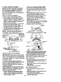
• Never carry passengers.
• Do not mow in reverse unless absolutely necessary. Always look down and
behind before and while backing.
• Be aware of the mower discharge direction and do not point it at anyone. Do
not operate the mower without either
the entire grass catcher or the guard in
place.
• Slow down before turning.
• Never leave a running machine unattended. Always turn oft blades, set park
ing brake, stop engine, and remove
keys before dismounting.
OPERATION
• Read, understand, and follow all instructions in the manual and on the machine
before starting.
• Only allow responsible adults, who are
familiar with the instructions, to operate
the machine.
• Clear the area of objects such as rocks,
toys, wire, etc., which could be picked
up and thrown by the blade.
• Be sure the area is clear of other people
before mowing. Stop machine if anyone
enters the area.
2
• Turn off blades when not mowing.
• Stop engine before removing grass
catcher or unclogging chute.
• Mow only in daylight or good artificial
light.
• Do not operate the machine while under
the influence of alcohol or drugs.
• Watch for traffic when operating near or
crossing roadways.
• Use extra care when _oading or unloading the machine
into a trailer or truck.
SLOPE OPERATION
Slopes are a major factor related to lossof-control and tipover accidents, which
can result in severe injury or death. All
slopes require extra caution. If you cannot
back up the slope or if you feel uneasy on
it, do not mow it.
DO:
• Mow up and down slopes, not across.
• Remove obstacles such as rocks, tree
limbs, etc.
• Watch for holes, ruts, or bumps. Uneven
terrain could overturn the machine. Tall
grass can hide obstacles.
• Use slow speed. Choose a low gear so
that you will not have to stop or shift
while on the slope.
• Follow the manufacturer's
recommen-
• Do nottry to stabilize the machine by
putting your foot on the ground.
• Do not use grass catcher on steep
slopes.
CHILDREN
Tragic accidents can occur ifthe operator
is not alert to the presence of children.
Children are often attracted to the
machine and the mowing activity. Never
assume that children will remain where
you last saw them.
• Keep children out of the mowing area
and under the watchful care of another
responsible adult.
• Be alert and turn machine off if children
enter the area.
• Before and when backing, look behind
and down for small children.
• Never carry children. They may fall off
and be seriously injured or interfere with
safe machine operation.
• Never allow children to operate the
machine.
• Use extra care when approaching blind
corners, shrubs, trees, or other bbjects
that may obscure vision.
SERVICE
• Use extra care in handling gasoline and
other fuels. They are flammable and
vapors are explosive.
Use only an approved container.
Never remove gas cap or add fuel
with the engine running. Allow engine to cool before refueling. Do not
smoke.
Never refuel the machine indoors.
Never store the machine or fuel
container inside where there is an
open flame, such as a water heater.
• Never run a machine inside a closed
dations for wheel weights or counterweights to improve stability.
• Use extra care with grass catchers or
other attachments.
These can change
the stability of the machine.
• Keep all movement on the slopes slow
and gradual. Do net make sudden
changes in speed or direction.
• Avoid starting or stopping on a slope. If
tires lose traction, disengage the blades
and proceed slowly straight down the
slope.
DO NOT"
• Do notturn on slopes unless necessary,
and then, turn slowly and gradually
downhill, if possible.
• Do not mow near drop-otis, ditches, or
embankments. The mower could sud-
area,
• Keep nuts and bolts, especially blade
attachment bolts, tight and keep equipment in good condition.
• Never tamper with safety devices.
Check their proper operation regularly.
• Keep machine free of grass, leaves, or
other debris build-up. Clean oil or fuel
spillage. Allow machine to cool before
storing.
• Stop and inspect the equipment if you
strike an object. Repair, if necessary,
denly turn over if a wheel is over the
edge of a cliff or ditch, or if an edge
caves in.
• Do not mow on wet grass. Reduced
traction could cause sliding.
3
before restarting.
• Never make adjustments or repairs with
the engine running.
• Grass catcher components are subject
to wear, damage, and deterioration,
which could expose moving parts or
allow objects to be thrown. Frequently
check components and replace with
manufacturer's recommended parts,
when necessary.
• Mower blades are sharp and can cut.
Wrap the blade(s) or wear gloves, and
use extra caution when servicing them.
• Check brake operation frequently.
Adjust and service as required.
• Be sure the area is clear of other people
before mowing. Stop machine if anyone
enters the area.
• Never carry passengers.
• Do not mow in reverse unless absolutely necessary. Always look down and
behind before and while backing.
• Never carry children. They may fall off
and be seriously injured or interfere with
safe machine operation.
• Keep children out of the mowing area
and under the watchful care of another
responsible adult.
• Be alert and turn machine off if children
enter the area.
• Before and when backing, look behind
and down for small children.
• Mow up and down slopes (15 ° Max), no
across.
• Remove obstacles such as rocks, tree
limbs, etc.
• Watch for holes, ruts, or bumps. Uneven
terrain could overtum the machine. Tall
grass can hide obstacles.
• Use slow speed. Choose a low gear so
that you will not have to stop or shift
while on the slope.
• Avoid starting or stopping on a slope. If
tires lose traction, disengage the blades
and proceed slowly straight down the
slope.
• Do not turn on slopes unless necessary,
and then, turn slowly and gradually
downhill, if possible.
,A Look for this symbol to point out important safety precautions. It means CAUTION!!! BECOME AWARE!!! YOUR SAFETY IS INVOLVED.
AWARNING:
The engine exhaust from
this product contains chemicals known to
the State of Califomia to cause cancer,
birth defects, or other reproductive harm,
,_,CAUTION: In order to prevent accidental starting when setting up, transporting,
adjusting or making repairs always disconnect spark plug wire and place wire where
it cannot contact spark plug.
4
PRODUCT
SPECIFICATIONS
GASOLINE
CAPACITY
AND TYPE:
1.25 GALLONS
UNLEADED
REGULAR
OILTYPE
SAE 10W30
API-SF/SG/SH):
We have competent, well-trained technicians and the proper tools to service or
repair this tractor.
Please read and retain this manual. The
instructionswill enable you to assemble
and maintain your tractor properly. Always
observe the "SAFETY RULES".
(above 32°F)
SAE 5W30
MAINTENANCE
(below 32°F)
AGREEMENT
OIL CAPACITY:
W/FILTER:
4.0 PINTS
W/O FILTER: 3.5 PINTS
A Sears Maintenance Agreement is available on this product. Contact your nearest
Sears store for details.
SPARK PLUG:
GAP: .040")
Champion RC12YC
CUSTOMER
VALVE CLEARANCE:
NOTADJUSTABLE
GROUND SPEED
FORWARD:
0-5.5
(MPH):
REVERSE:
0- 2.4
TIRE PRESSURE:
FRONT: 14PSI
REAR: 10 PSI
CHARGING
SYSTEM:
15 AMPS @ 3600RPM
BATTERY:
AMP/HR: 30
MIN. CCA: 240
CASE SIZE: UlR
BLADE BOLT
TORQUE:
27-35 FT. LBS.
RESPONSIBILITIES
• Read and observe the safety rules.
• Follow a regular schedule in maintaining, caring for and using your tractor.
• Follow the instructionsunder "Maintenance" and "Storage" sections of this
owner's manual.
,AWARNING: This tractor is equipped
with an internal combustion engine and
should not be used on or near any unimproved forest-covered, brush-covered or
grass-covered land unless the engine's
exhaust system is equipped with a spark
arrester meeting applicable local or state
laws (if any). If a spark arrester is used, it
should be maintained in effective working
order by the operator.
In the state of California the above is
required by law (Section 4442 of the
California Public Resources Code). Other
states may have similar laws. Federal
laws apply on federal lands. A spark
arrester.for the muffler is available through
your nearest Sears Authorized Service
Center (See REPAIR PARTS section of
this manual).
CONGRATULATIONS on your purchase
of a Craftsman Tractor. It has been
designed, engineered and manufactured
to give you the best possible dependability
and performance.
Should you experience any problem you
cannot easily remedy, please contact your
nearest Sears Authorized Service Center.
5
PARTS BAG CONTENTS SHOWN FULL SIZE
(1) Large Flat Washer
(1) Hex Bolt
3/8-16 x 1
O
(1)Lockwasher
3/8
(1) Hex Bolt
5/16-18x 1-1/4
(1) Locknut
5/16-18
(1) Shoulder Bolt
5/16-18
©
(1) Knob
(1) Washer
17/32 x 1-3/16 x 12 Gauge
6
PARTS BAG CONTENTS
Washers #10
(2) Lock
(2) Screws #10 x 5/8
(2) Weld
Nuts
#10
i
I
Parts packet separately in carton
Seat
SHOWN FULL SIZE
3/16 x 3/4 x 16
(2) Washers
Gauge
Parts Bag contents not shown full size
Video
Cassette
(2) Latch Hook
Assemblies
Steering
Wheel Insert
Icher
Steedng Wheel
Adapter
<:_
(2) Keys
Steering
Slope Sheet
Manual
Parts Bag'
7
Steering
Extension
Shaft
o
Your new tractor has been assembled at the factory with exception of those parts left
unassembled for shipping purposes. To ensure safe and proper operation of your tractor
all parts and hardware you assemble must be tightened securely. Use the correct tools
as necessary to insure proper tightness. Review the video cassette before you begin.
TOOLS REQUIRED FOR
ASSEMBLY
_-_-.-Insert
_"
318Hex Bolt
A socket wrench set will make assembly
easier. Standard wrench sizes you need
are listed below.
(1) 9/16" wrench
(1) 3/4" Socket w/
(1) Pliers
drive ratchet
(2) 1/2" wrench
(1) Phillips Screw(1) Utility knife
driver
(1) Tire pressure gauge
When right or left hand is mentioned in
this manual, it means, from your point of
view when you are in the operating position (seated behind the steering whee ).
Steering Wheel
_
Adapter
_ 5/16 Hex
5/16 Locknut _-_._,../
Lower
UNPACK CARTON
• Remove all accessible loose parts and
parts boxes from shipping carton (See
page 6).
• Cut, from top to bottom, along lines on
all four corners of shipping carton, and
lay panels flat.
• Check for any additional loose parts or
boxes and remove.
^
.
_teenng I
Shaft
,
Bolt
'" _ '_'' _'-'--"
.,'L_ ,__,
l)
7"-'-._'I_,,',
Tab
i
Slots
• Remove protective materials from tractor hood and grill.
IMPORTANT: Check for and remove any
staples in skid that maypuncture tires
where tractor is to roll offskid.
BEFORE ROLLING TRACTOR OFF
SKID
STEERING
Boot
Tabs
E_ension Shaft
TO REMOVE TRACTOR FROM
CARTON
ATTACH
_
TO ROLL TRACTOR OFF SKID (See
Operation section for location and
function of controls)
WHEEL
ASSEMBLE EXTENSION SHAFT AND
BOOT
• Slide extension shaft onto lower steering shaft. Align mounting holes in extension and lower shafts and install 5/16
hex bolt and Iocknut. Tighten securely.
IMPORTANT: Tighten bolt and nut securely to 18-22 ft. Ibs. torque.
• Place tabs of steedng boot over tab
slots in dash and push down to secure.
itshighest
i ment
Press lift
liftlever
leverto
plunger
and position.
raise attachRelease parking brake by depressing
clutch/brake pedal.
• Place freewheel control in freewheeling
position to disengage transmission (See
=TO TRANSPORT" in the Operation
section of this manual). ,
• Roll tractor forward offskid.
• Remove banding holding discharge
guard up against tractor.
INSTALL STEERING WHEEL
• Position front wheels of the tractor so
they are peintingstraight
forward.
• Slide steedng wheel adapter onto steering shaft extension.
• Position Steering wheel so cross bars
are horizontal (left to dght) and slide
inside boot and onto adapter.
• Assemble large fiat washer, 3/8 lock
washer, 3/8 hex bolt and tighten securely.
• Snap steedng wheel insert into center
of steering wheel.
8
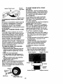
HOW TO SET UP YOUR TRACTOR
CHECK BATTERY
• Lift seat pan to raised position and open
battery box door.
• If this battery is put into service after
month and year indicated on label (label
located between terminals) charge battery for minimum of one hour at 6-10
amps. (See "BATTERY" in Maintenance
section of this manual for charging
instructions).
Seat Pan
Label
Battery
Terminal
Seat
Seat Pan
Shoulder Bolt
Adjustment
Knob
CHECK TIRE PRESSURE
The tires on your tractor were overinflated
at the factory for shipping purposes.
Correct tire pressure is important for best
cutting performance,
• Reduce tire pressure to PSi shown in
"PRODUCT SPECIFICATIONS" section
of this manual.
CHECK
INSTALL SEAT
Adjust seat before tightening adjustment
knob.
• Remove cardboard packing on seat pan.
Place seat on seat pan and assemble
shoulder bolt. Tighten shoulder bolt
securely,
• Assemble adjustment knob andflat
washer loosely. Do not tighten.
• Lower seat into operating position and
sit on seat.
• Slide seat until a comfortable position is
reached which allows you to press
clutch/brake pedal all the way down,
• Get off seat without moving its adjusted
position.
• Raise seat and tighten adjustment knob
securely.
Flat
Washer
DECK LEVELNESS
For best cutting results, mower
should be properly leveled. See
LEVEL MOWER HOUSING" in
and Adjustments section of this
housing
"TO
the Service
manual.
CHECKFORPROPERPOSITIONOF
ALL BELTS
Seethe figuresthat are shownfor replac-
_,CAUTION:
Do not remove discharge
guard from mower. Raise and hold guard
when attaching mulcher plate and allow it
to rest on plate while in operation.
TO CONVERT TO BAGGING OR
DISCHARGING
Simply remove mulcher plate and store in
a safe place. Your mower is now ready for
discharging or installation of optional
grass catcher accessory.
NOTE: It is not necessary to change
blades. The mulcher blades are designed
for discharging and bagging also.
ing motion and mower blade drive belts in
the Service and Adjustments sectoin of
this manual. Verify that the belts are routed correctly.
CHECK BRAKE SYSTEM
After you learn how to operate your tractor, check to see that the brake is properly
adjusted. See "TO ADJUST BRAKE" in
the Service and Adjustments section of
this manual.
INSTALL MULCHER
PLATE
• Install two latch hooks to mulcher plate
using screw, washer, lock washer, and
weld nut as shown.
NOTE: Pre-assemble weld nut to latch
t/CHECKLIST
PLEASE REVIEW
CHECKLIST:
v' All assembly instructions have been
completed.
No remaining loose parts in carton.
t/ Battery is propedy prepared and
charged. (Minimum 1 hour at 6 amps).
v' Seat is adjusted comfortably and
tightened securely.
v' All tires are properly inflated. (For
shipping purposes, the tires were
overinflated at the factory).
Be sure mower deck is propedy leveled
side-to-side/front-to-rear
for best
cutting results. (Tires must be properly
inflated for leveling).
Check mower and drive belts. Be sure
they are routed properly around pulleys
and inside all belt keepers.
1/ Check wiring. See that all connections
are still secure and wires are properly
clamped.
Before driving tractor, be sure freewheel control is in drive position.
hook by inserting weld nut from the top
with hook pointing down.
• Tighten hardware securely.
• Raise and hold deflector shield in upright position.
• Place front of mulcher plate over front of
mower deck opening and slide into
place, as shown.
• Hook front latch into hole on front of
mower deck.
• Hook rear latch into hole on back of
mower deck.
Weld Nut From
The Top
Weld
Hook Points
Down
Lock
Washer
Latch
Latch
WHILE LEARNING HOW TO USE YOUR
TRACTOR,
PAY EXTRAATTENTION
TO
THE FOLLOWING
IMPORTANT ITEMS:
Nut
Lock Washer
Washer
Washer
Mulcher
Plate
_
THE FOLLOWING
,/
•/
Screw
,/
Deflector
Shield
•/
4
Latch Hooks
10
Engine oil is at proper level.
Fuel tank is filled with fresh, clean,
regular unleaded gasoline.
Become familiar with all controls - their
location and function. Operate them
before you start the engine.
Be sure brake system is in safe operating condition.
It is important to purge the transmission before operating your tractor for
the first time. Follow proper starting
and transmission purging instructions
(See "TO START ENGINE" and
"PURGE TRANSMISSION"
in the Operation section of this manual).
These symbols may appear on your tractor or in literature supplied with the product.
Learn and understand their meaning.
BATTERY
CAUTION OR
WARNING
REVERSE
ENGINE ON
ENGINE OFF
OIL PRESSURE
LIGHTS ON
FUEL
CHOKE
MOWER HEIGHT
PARKING BRAKE
LOCKED
R N
ATTACHMENT
CLUTCH ENGAGED
REVERSE
NEUTRAL
ATTACHMENT
IGNITION
FORWARD
FAST
OVER TEMP
LIGHT
H
L
HIGH
LOW
KEEP AREA CLEAR
CLUTCH DISENGAGED
SLOW
UNLOCKED
!
MOWER LIFT
PARKING BRAKE
SLOPE HAZARDS
(SEE SAFETY RULES SECTION)
FREE WHEEL
DANGER, KEEP HANDS AND FEET AWAY
(Automatic Models only)
11
KNOW YOUR
TRACTOR
READ THIS OWNER'S MANUAL AND SAFETY RULES BEFORE OPERATING
YOUR TRACTOR
Compare the illustrationswith your tractor to familiarize yourself with the locations of
various controls and adjustments. Save this manual for future reference.
Attachment
Clutch Lever
Light Switch
Position
Ignition
Switch
Ammeter
Lift Lever
Throttle/Choke
Control
Plunger
©
Attachment
Lift Lever
Pedal
Height
Adjustment
Parking Brake
Freewheel
Control
Knob
rox._
Speed
,_P
,, Motion
Control Lever
I=1_'0 I
3MPH I_ I
_
2MPH
I
1MP_
Our tractors conform to the safety standards of the American
National Standards Institute.
ATTACHMENT
CLUTCH
LEVER:
ATTACHMENT LIFT LEVER: Used to
raise and lower the mower deck or other
attachments mounted to your tractor.
LIFT LEVER PLUNGER: Used to release
attachment lift lever when changing its
position.
IGNITION SWITCH: Used for starting and
stopping the engine.
AMMETER: Indicates battery charging (+)
or discharging (-).
PARKING BRAKE: Locks clutch/brake
into the brake position.
HEIGHT ADJUSTMENT KNOB - Used to
adjust the mower cutting height.
Used to
engage the mower blades, or other attachments mounted to your tractor.
LIGHT SWITCH: Tums the headlights on
and off.
THROTTLE/CHOKE
CONTROL: Used to
control engine speed.
CLUTCH/BRAKE
PEDAL:
Used for
declutching and braking the tractor and
starting the engine.
FREEWHEEL
CONTROL:
Disengages
transmission for pushing or slowly towing
the tractor with the engine off.
MOTION CONTROL
LEVER: Selects the
speed and direction of the tractor.
12
The operation of any tractor can result in foreign objects thrown into the
eyes, which can result in severe eye damage. Always wear safety glasses
or eye shields while operating your tractor or performing any adjustments c
repairs. We recommend a wide vision safety mask over spectacles, or stan
dard safety glasses.
HOW TO USE YOUR TRACTOR
before stopping
"backfire".
TO SET PARKING BRAKE
Your tractor is equipped with an operator
presence sensing switch. When engine is
running, any attempt by the operator to
leave the seat without first setting the
parking brake will shut off the engine.
•Tum ignition key to "OFF" position and
remove key. Always remove key when
leaving tractor to prevent unauthorized u,'
• Never use choke to stop engine.
IMPORTANT:
Leaving the ignition switc
in any position other than "OFF" will cau:
the battery to be discharged
(dead).
NOTE: Under certain conditions when
• Depress clutch/brake
pedal into full
"BRAKE" position and hold.
• Place parking brake lever in "ENGAGED" position and release pressure
from clutch/brake
pedal. Pedal should
remain in "BRAKE" position. Make sure
parking brake will hold tractor secure.
Throttle/Choke
Attachment Clutch
Height
tractor is standing idle with the engine rul
ning, hot engine exhaust gases may
cause "browning" of grass. To eliminate
this possibility, always stop engine when
_t_pcPing tractor on grass areas.
AUTION: Always stop tractor completely, as described above, before leavir
the operator's position, to empty grass
catcher, etc.
THROTTLE
CONTROL
Lever "Engaged"
Position
_
Adjustment
Knob
"Disengaged"
Always operate engine at full throttle,
• Operating engine at less than full throt
tie reduces the battery charging rate.
• Full throttle offers the best bagging am
mower performance.
TO MOVE FORWARD AND BACKWAR.
Parking Brake
"Engaged"
Position
"Brake"
Position
The direction and speed of movement is
controlled by the motion control lever.
• Start tractor w!th motion control lever in
neutral (N) position.
• Release parking brake and clutch/brak_
pedal,
• Slowly move motion control lever to
desired position.
TO ADJUST MOWER CUTTING HEIGH_
Control Lever
Cinch/Brake Pedal
"Ddve" Position
"Disengaged"
Position
STOPPING
MOWER
BLADES
may cause engine to
-
• To stop mower blades, move attachment clutch Lever to =DISENGAGED"
position.
GROUND DRIVE -
The cutting height is controlled by turning
the height adjustment knob in desired
direction.
• To stop ground ddve, depress
clutch/brake pedal into full =BRAKE" position.
• Move motion control lever to neutral (N)
position.
IMPORTANT: The motion control lever
does not return to neutral (N) position
when the clutchforake pedal is depressed.
ENGINE -
• Turn knob clockwise (G) to raise cuttinc
height.
• Turn knob countemlockwise (_) to
lower cutting height.
The cutting height range is approximately
1-1/2" to 4". The heights are measured
from the ground to the blade tip with the
engine not running. These heights are ap
proximate and may vary depending upon
soil conditions, height of grass and types
of grass being mowed.
• Move throttle control to slow position.
NOTE: Failure to move throttle control to
slow position and allowing engine to idle
13
• The average lawn should be cut to
approximately 2-1/2 inches during the
cool season and to over 3 inches during
hot months. For healthier and better
looking lawns, mow often and after
moderate growth.
• For best cutting performance, grass
over 6 inches in height should be
mowed twice. Make the first cut relatively high; the second to desired height.
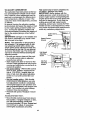
TO ADJUST GAUGE WHEELS
ACAUTION:
Do not operate the mower
without either the entire grass catcher, on
mowers so equipped, Or the discharge
guard in place.
Attachment _ ._
ClutchLever_
=Engaged" _,f-],,_.
Position
"Disengaged"/ _'T=
_._
F,/_
Guard
_ OPERATE ON HILLS
CAUTION: Do not drive up or down
hillswith slopes greater than 15° and do
not ddve across any slope. Use the slope
guide provided at the back of this manual.
• Choose the slowest speed before starting up or down hills.
• Avoid stopping or changing speed on
hills.
• If slowing is necessary, move throttle
control lever to slower position.
• If stopping is absolutely necessary, push
clutch/brake pedal quickly to brake position and engage parking brake.
• Move motion control lever to neutral (N)
position.
IMPORTANT: The motion control lever
does not retum to neutral (N) position
when the clutch/brake pedal is depressed.
• To restart movement, slowly release
parking brake and clutch/brake pedal.
• Slowly move motion control lever to
slowest Setting.
• Make all tums slowly.
Gauge Wheel
Mounting
Bracket
3/8-16
Gauge Wheel
/ "/111I +;'
Pos
Gauge wheels are properly adjusted
when they are slightly off the ground when
mower is at the desired cutting height in
operating position. Gauge wheels then
keep the deck in proper position to help
prevent scalping in most terrain conditions.
• Adjust gauge wheels with tractor on a
fiat level surface.
• Adjust mower to desired cutting height
(See =TO ADJUST MOWER CUTTING
HEIGHT" in the Operation section of _
this manual).
• With mower in desired height of cut position, gauge wheels should be assembled so they are slightly off the ground.
Install gauge wheel in appropriate hole
with shoulder belt, 3/8 washer, and 3/816 Iocknut and tighten securely.
• Repeat for opposite side installing
gauge wheel in same adjustment hole.
3/8 Washer
Attachment Lift
tb_-everHighPosition
Shoulder
Bolt
TO TRANSPORT
TO OPERATE MOWER
Your tractor is equipped with an operator
presence sensing switch. Any attempt by
the operator to leave the seat with the
engine running and the attachment clutch
engaged will shut off the engine.
• Select desired height of cut.
• Lower mower with attachement lift control.
• Start mower blades by engaging attachment clutch control.
• TO STOP MOWER BLADES - disengage attachment clutch control.
14
When pushing or towing your tractor, be
sure to disengage transmission by placing
freewheel control in freewheeling position. Freewheel control is located at the
rear drawbar of tractor.
• Raise attachment lift to highest position
with attachment lift control.
• Pull freewheel control out and down into
the slot and release so it is held in the
disengaged position.
• Do not push or tow tractor at more than
two (2) MPH.
• To reengage transmission, reverse
above procedure.
NOTE: Toprotecthoodfrom damage
when transportingyourtractoron a truck
or a trailer,be sure hoodis closed and
securedto tractor. Usean appropdate
meansof tying hoodto tractor(rope,cord,
etc.).
TOWING CARTS AND OTHER
ATTACHMENTS
Tow only the attachments that are recommended by and comply with specifications
of the manufacturer of your tractor. Use
common sense when towing. Too heavy of
a load, while on a slope, is dangerous.
Tires can lose traction with the ground and
cause you to lose control of your tractor.
BEFORE STARTING THE ENGINE
CHECK ENGINE OIL LEVEL
• The engine in your tractor has been
shipped, from the factory, already filled
with summer weight oil.
• Check engine oil with tractor on level
ground.
• Unthread and remove oil fill cap/dipstick; wipe oil off. Reinsert the dipstick
into the tube and rest oil fill cap on the
tube. Do not thread the cap onto the
tube. Remove and read oil level. If necessary, add oil until =FULL" mark on
dipstick is reached. Do not overfill.
• For cold weather operation you should
change oil for easier starting (See =OIL
VISCOSITY CHART" in the
Maintenance section of this manual).
• To change engine oil, see the
Maintenance section in this manual.
ADD GASOLINE
• Fill fuel tank. Use fresh, clean, regular
unleaded gasoline with a minimum of 87
octane. (Use of leaded gasoline will
increase carbon and lead oxide
deposits and reduce valve life). Do not
mix oil with gasoline. Purchase fuel in
quantities that can be used within 30
days to assure fuel freshness.
IMPORTANT: When operating in temperatures below 32°F(0°C), use fresh, clean
winter grade gasoline to help insure good
cold weather starting.
AWARNING:
Expedence indicates that
alcohol blended fuels (called gasohol or
using ethanol or methanol) can attract
moisture which leads to separation and
formation of acids during storage. Acidic
gas can damage the fuel system of an
engine while in storage. To avoid engine
problems, the fuel system should be emptied before storage of 30 days or longer.
Drain the gas tank, start the engine and let
it run untilthe fuel lines and carburetor are
empty. Use fresh fuel next season. See
Storage Instructionsfor additional information. Never use engine or carburetor
cleaner products in the fuel tank or perma,_nctdamage may occur.
AUTION: Fill to bottom of gas tank
filler neck. Do not overfill. Wipe off any
spilled oil or fuel. Do not store, spill or use
gasoline near an open flame.
TO START ENGINE
When starting the engine for the first time
or if the engine has run out of fuel, it will
take extra cranking time to move fuel from
the tank to the engine.
• Be sure freewheel control is in the
transmission engaged position..
•
onse . opera,
rigpo on,deprsss
dutch rak ped.and paringbrake.
• Place motion control lever in neutral (N)
position.
• Move attachment clutch to =DISENGAGED" position.
• Move throttle control to choke position.
NOTE: Before starting, read.the warm and
cold starting procedures below.
• Insert key into ignition and tum key
clockwise to =START" position and
release key as soon as engine starts.
Do not run starter continuously for more
than fifteen seconds per minute. If the
engine does not start after set,eral
attempts, move throttle control to fast
position, wait a few minutes and try
again. If engine still does not start,
move the throttle control back to the
choke position and retry.
WARM WEATHER STARTING (50 ° F and
above)
• When engine starts, move the throttle
control to the fast position.
• The attachments and ground drive can
now be used. If the engine does not
accept the load, restart the engine and
allow it to warm up for one minute using
the choke as described above.
15
COLD WEATHER STARTING ( 50 ° F and
below)
• When engine starts, allow engine to run
with the throttle control in the choke
position until the engine runs roughly.,
then move throttle control to fast posP
tion, This may require an engine warmup period from several seconds to several minutes, depending on the temperature.
AUTOMATIC TRANSMISSION
WARM UP
• Before driving the unit in cold weather,
the transmission should be warmed up
as follows:
• Be sure the tractor is on level ground.
• Place the motion control lever in neutral.
Release the parking brake and let the
clutch/brake slowly return to operating
position.
• Allow one minute for transmission to
warm up. This can be done during the
engine warm up pedod.
• The attachments
can also be used during the engine warm-up period after the
transmission
has been warmed up.
NOTE: At a high altitude (above 3000
feet) or in cold temperatures
(below 32 F)
the carburetor fuel mixture may need to be
adjusted for best engine performance.
See "TO ADJUST CARBURETOR"
in the
Service and Adjustments
section of this
manual.
,_RGE
TRANSMISSION
CAUTION: Never engage or disengage freewheel lever while the engine is
running.
To ensure proper operation and performance, it is recommended that the transmission be purged before operating tractor
for the first time. This procedure will
remove any trapped air inside the transmission which may have developed dudng
shipping of your tractor.
IMPORTANT:
Should your transmission
require removal for service or replacement, it should be purged after reinstallation before operating the tractor.
• Place tractor safely on level surface with
engine off and parking brake set.
• Disengage transmission by placing freewheel control in freewheeling position
(See "TO TRANSPORT" in this section
of manual).
• Sitting in the tractor seat, start engine.
After the engine is running, move throttle control to slow position. With motion
control lever in neutral (N) position,
slowly disengage clutch/brake pedal.
• Move motion control lever to full forward
position and hold for five (5) seconds.
Move lever to full reverse position and
hold for five (5) seconds. Repeat this
procedure three (3) times.
NOTE: During this procedure there will be
no movement of drive wheels. The air is
being removed from hydraulic drive system.
• Move motion control lever to neutral (N)
position. Shut off engine and set parking
brake.
• Engage transmission by placing freewheel control in driving position (See
"TO TRANSPORT" in this section of
manual).
• Sitting in the tractor seat, start engine.
After the engine is running, move throttle control to half (1/2) speed. With
motion control lever in neutral (N) position, slowly disengage clutch/brake
pedal.
• Slowly move motion control lever forward; after the tractor moves approximately five (5) feet, slowly move motion
control lever to reverse position. After
the tractor moves approximately five (5)
feet return the motion control lever to
the neutral (N) position. Repeat this procedure with the motion control lever
three (3) times.
• Your tractor is now purged and ready for
normal operation.
1R
MOWING
MULCHING
TIPS
Service and Adjustments section of this
manual.
• The left hand side of mower should be
used for trimming.
• Ddve so that clippingsare d=scha_
onto
b_earea that has been cut. Have _e cut area
to the rightof the tractor. This wll result in a
more even distributionof clippingsand more
uniformcutting.
• When mowing large areas, start by turning to the right so that clippings will discharge away from shrubs, fences, driveways, etc. After one or two rounds, mow
in the opposite direction making left
hand turns until finished.
• If grass is extremely tall, it should be
mowed twice to reduce load and possible fire hazard from dried clippings.
Make first cut relatively high; the second
to the desired height.
• Do not mow grass when it is wet. Wet
grass will plug mower and leave undesirable clumps. Allow grass to dry
before mowing.
• Always operate engine at full throttle
when mowing to assure better mowing
performance and proper discharge of
material. Regulate ground speed by selecting a low enough gear to give the
mower the best cutting performance as
well as the quality of cut desired.
• When operating attachments, select a
ground speed that will suit the terrain
and give best performance of the attachment being used.
f
t
ii
TIPS
IMPORTANT: For best performance, keep
mower housing free of built-up grass and
trash. Clean after each use.
• The special mulching blade will recut
the grass clippings many times and
reduce them in size so that as they fall
onto the lawn they will disperse into the
grass and not be noticed. Also, the
mulched grass will biodegrade quickly
to provide nutrients for the lawn. Always
mulch with your highest engine (blade)
speed as this will provide the best recutting action of the blades.
• Avoid cutting your lawn when it is wet.
Wet grass tends to form clumps and
interferes with the mulching action. The
best time to mow your lawn is the early
afternoon. At this time the grass has
dried and the newly cut area will not be
exposed to the direct sun.
• For best results, adjust the mower cutting height so that the mower cuts oft
only the top one-third of the grass
blades. For extremely heavy mulching,
reduce your width of cut on each pass
and mow slowly.
• Certain types of grass and grass conditions may require that an area be
mulched a second time to completely
hide the clippings. When doing a second cut, mow across or perpendicular to
the first cut path.
• Change your cutting pattern from week
to week. Mow north to south one week
then change to east to west the next
week. This will help prevent matting and
graining of the lawn.
• Mower should be properly leveled for
best mowing performance. See "TO
LEVEL MOWER HOUSING" in the
1
MOWING
J
17
CUSTOMER
RESPONSIBILITIES
RLL IN DATES
AS*OOCO.
REGULAR SERVICE
Chock
Operation
Check Brake
Tire Pressure
ATES
_
Check Operator Presence and
T Interlock Systems
R Check
forLoose
Fasteners
I_
_
_7
T Lubr_,onC_
A
0
R
I/
Sharpen/Replace
Check
Battely Level
Mower Blades
i4
Clean Batteq/and Terminals
II_
Check TransaxlaCooling
I_
Adjust Blade Belt(s) Tens_n
_s
Adjust Motion Ddve Bstt(s) Tension
Check EngineOi_Level
Ks
I_
ll_
ChangeEngineOil
N
c_an
I#/t,ti
a
I_
Air Screen
InspectMufflar/SparkArrestor
•
V'
Replace Oil Filter (if equipped)
N
_,2
Replace Spark Plug
Clean EngineCoolingRns
_i
V'
Replace Air Filter Paper Cartridge
Replace Fuel Filter
I_
1 _Ctmnge more onen when _0emUng und_ s heaw I_d o( in high mntde_ _mtur_
2 -Senf, ce m_re oitln whe_ operating in _dy or dusty conditions.
3. Hequippad with _ flits, dlange oil m_rf 50 hour=.
4. Replace t_des more oltefl w_n mowing In un_y soa.
GENERAL
RECOMMENDATIONS
The warranty on this tractor does not cover
items that have been subjected to operator abuse or negligence. To receive full
value from the warranty, operator must
maintain tractor as instructed in this
manual. Some adjustments will need to
be made periodically to properly maintain
your tractor.
All adjustments in the Service and Adjustments section of this manual should be
checked at least once each season.
• Once a year you should replace the
spark plug, clean or replace air filter,
and check blades and belts for wear. A
new spark plug and clean air filter assure proper air-fuel mixture and help
your engine run better and last longer.
BEFORE EACH USE
•
•
•
•
•
5 - ff equipped with idJustal_e sln_em.
S - N_ required If equipped w_h rrmintonance-lree batter/.
7 - Tighten fmnl sxte ph_ bo_ to 35 ft.4)s, mQ_mum.
DO r_ ow_lghten.
LUBRICATION
CHART
OSpindle
Zerk
OFmnt Wheel
Bearing Zerk
OFront
Wheel
Bearing
Zerk
OEngine
Q General Purpose Grease
• Refer to Maintenance "Engine"Section
IMPORTANT:
Do not oil or grease the pivot
points which have special nylon bear-ings.
Check engine oil level.
Viscous lubricants will attract dust and dirt
Check brake operation.
that will shorten the life of the self-lubricatCheck tire pressure.
ing bearings. If you feel they must be lubriCheck operator presence and interlock
cated, use only a dry, powdered graphite
type lubricant sparingly.
systems for proper operation.
18
Check for loose fasteners.
TRACTOR
Alwaysobservesafetyruleswhen performing any maintenance.
BRAKE OPERATION
If tractor requires more than six (6) feet
stopping distance at high speed in highest
gear, then brake must be adjusted. (See
'q'O ADJUST BRAKE" in the Service and
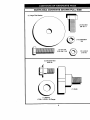
• Reassemble hex bolt, lock washer and
flat washer in exact order as shown.
• Tighten bolt securely (27-35 Ft. Lbs.
torque).
IMPORTANT:
Blade bolt is Grade 8 heat
treated.
Trailing
Ed
Adjustments section of this manual).
TIRES
• Maintain proper air pressure in all tires
(See "PRODUCT SPECIFICATIONS"
section of this manual).
• Keep tires free of gasoline, oil, or insect
control chemicals which can harm rubber.
• Avoid stumps, stones, deep ruts, sharp
objects and other hazards that may
cause tire damage.
PRESENCE
Mandrel Assembly
Center
Hex Bolt_
(Grade 8)_,
_? Rat
*A Grade 8 heat treated bolt can be
identified by six lines on the bolt head.
TO SHARPEN BLADE
NOTE: We do not recommend sharpening
blade, but if you do, be sure the blade is
balanced.
Care should be taken to keep the blade
balanced. An unbalanced blade will cause
excessive vibration and eventual damage
to mower and engine.
• The blade can be sharpened with a file
or on a grinding wheel. Do not attempt
to sharpen while it is on the mower.
• To check blade balance, you will need a
5/8" diameter steel bolt, pin, or 6 cone
balancer. (When using a cone balancer,
follow the instructionssupplied with balancer).
NOTE: Do not use a nail for balancing
blade. The lobes of the center hole may
appear to be centered, but are not.
• Slide blade onto an unthreaded portion
of the steel bolt or pin and hold the bolt
or pin parallel with the ground. If blade
is balanced, it should remain in a horizontal position. If either end of the blade
moves downward, sharpen the heavy
end until the blade is balanced.
NOTE: To seal tire punctures and prevent
flat tires due to slow leaks, tire sealant
may be purchased from your local parts
dealer. Tire sealant also prevents tire dry
rot and corrosion.
OPERATOR
Blade
SYSTEM
Be sure that operator presence and interlock systems are working properly. If your
tractor does not function as described
below, repair the problem immediately.
• The engine should not start unless the
clutch/brake pedal is fully depressed
and attachment clutch control is in the
disengaged position.
• When the engine is running, any
attempt by the operator to leave the
seat without first setting the parking
brake should shut off the engine.
• When the engine is running and the
attachment clutch is engaged, any
attempt by the operator to leave the
seat should shut off the engine.
• The attachment clutch should never
operate unless the operator is in the
seat.
BLADE CARE
For best results mower blades must be
kept sharp. Replace bent or damaged
blades.
BLADE REMOVAL
• Raise mower to highest position to allow
access to blades.
• Remove hex bolt, lock washer and flat
washer securing blade.
• Install new or resharpened blade with
trailing edge up towards deck as shown.
IMPORTANT: To ensure proper assembly,
center hole in blade must. align with star
on mandrel assembly.
Center Hole
5/8"
or Pin
BATTERY
Your tractor has a battery charging system
which is sufficient for normal use,
However, periodic charging of the battery
with an automotive charger will extend its
life.
•
•
•
•
19
Keep battery and terminals clean.
Keep battery bolts tight.
Keep small vent holes open.
Recharge at 6-10 amperes for I hour.
NOTE:The originalequipmentbatteryon
your tractoris maintenancefree. Do not
attemptto open or removecaps or covers.Addingor checkinglevel of electrolyte
is not necessary.
TOCLEANBATTERYANDTERMINALS
Change the oil after every 50 hours of opCorrosionand dirt on the batteryandter- eration or at least once a year if the tractor
minalscan causethe batteryto =leak"
is not used for 50 hours in one year.
TEMPERATURE
F_t_E
ANTICIPATED
BEFORE
NEXT OIL CHANGE
power.
• Open battery box door.
• Disconnect BLACK battery cable first
then RED battery cable and remove
battery from tractor.
• Rinse the battery with plain water and
dry.
• Clean terminals and battery cable
ends with wire brush until bright.
• Coat terminals with grease or petroleum jelly.
• Reinstall battery (See =REPLACING
BATTERY" in the SERVICE AND AD-
Check the crankcase oil level before starting the engine and after each eight (8)
hours of operation. Tighten oil fill cap/dipstick securely each time you check the oil
level.
JUSTMENTS
section of this manual).
V-BELTS
Check V-belts for deterioration and wear
• Remove oil fill cap/dipstick. Be careful
not to allow dirt to enter the engine
when changing oil.
• Remove drain plug.
• After oil has drained completely, replace oil drain plug and tighten securely.
• Refill engine with oil through oil fill dipstick tube. Pour slowly. Do not overfill.
For approximate capacity see =PRODUCT SPECIFICATIONS"
section of this
manual.
after 100 hours of operation and replace
if necessary. The belts are not adjustable. Replace belts if they begin to slip
from wear.
TRANSAXLE
COOLING
The transmission fan and cooling fins
should be kept clean to assure proper
cooling.
Do not attempt to clean fan or transmission while engine is running or while the
transmission is hot.
• Inspect cooling fan to be sure fan
blades are intact and clean.
• Inspect cooling fins for dirt, grass clip
pings and other materials. To prevent
damage to seals, do not use compressed air or high pressure sprayer to
clean cooling fins.
TRANSAXLE
PUMP FLUID
The transaxle was sealed at the factory
and fluid maintenance is not required for
the life of the transaxle. Should the
TO CHANGE
ENGINE
OIL
Determine temperature range expected
before oil change. All oil must meet API
service classification SF, SG, or SH.
• Be sure tractor is on level surface.
• Oil will drain more freely when warm.
• Catch oil in a suitable container.
• Use gauge on oil fill cap/dipstick for
checking level. Insert dipstick into the
tube and rest the oil fill cap on the tube.
Do not thread the cap onto the tube
when taking reading.
Keep oil at
=FULL" line on dipstick. Tighten cap
onto the tube securely when finished.
Air Cleaner
Cover Knob
Cover
Foam
Nut
Pre-Cleane
Grommet
transaxle ever leak or require servicing,
contact your nearest authorized service
center/department.
Air
ENGINE
Paper "
Cartridge
LUBRICATION
Only use high quality detergent oil rated
with API service classification SF, SG, or
SH. Select the oil's SAE viscosity grade
according to your expected operating
temperature.
,.Air Cleaner
Base
Dipstick
Drain Rug
2O
or every other oil change if the tractor is
used more than 100 hours in one year.
• Drain oil from engine crankcase (See
='1"OCHANGE ENGINE OIL" in this section of this manual, through step remove
drain plug).
• Remove oil filter and wipe off filter
adapter.
• Apply a thin coating of new engine oil to
the rubber gasket on replacement oil filter.
CLEAN AIR SCREEN
Air screen must be kept free of dirt and
chaff to prevent engine damage from overheating. Clean with a wire brush or compressed air to remove dirt and stubborn
dried gum fibers.
AIR
FILTER
Your engine will not run properly using a
dirty air filter. Clean the foam pre-cleaner
after every 25 hours of operation or every
season. Service paper cartridge every
100 hours of operation or every season,
whichever occurs first.
Service air cleaner more often under dusty
conditions.
• Remove knob and cover.
• Install replacement oil filter on filter
adapter. Turn oil filter clockwise until
rubber gasket contacts the filter adapter,
then tighten filter an additional 1/2 turn.
• Fill crankcase with new oil (See "TO
CHANGE ENGINE OIL" in this section
• Remove wing nut and air cleaner from
base.
TO SERVICE
of this manual). For approximate capacity see "PRODUCT
SPECIFICATIONS"
section of this manual.
PRE-CLEANER
• Start the engine and check for oil leaks.
Correct any leaks before placing engine
into full operation.
• Slide foam pre-cleaner off cartridge.
• Wash it in liquid detergent and water.
• Squeeze it dry in a clean cloth. Allow it
to dry.
• Saturate it in engine oil Wrap it in
clean, absorbent cloth and squeeze to
remove excess oil.
TO SERVICE
CARTRIDGE
• Replace a dirty, bent, or damaged _artfidge.
NOTE: Do not wash the paper cartridge
or use pressurized air, as this will damage
the cartridge.
• Reinstall the pre-cleaner (cleaned and
oiled) over the paper cartridge.
• Reassemble air cleaner, wing nut, cover
and tighten knob securely.
CLEAN AIR INTAKE/COOLING
AREAS
•Oil Filter/
MUFFLER
Inspect and replace corroded muffler and
spark arrester (if equipped) as it could create a fire hazard and/or damage.
To insure proper cooling, make sure the
grass screen, cooling fins, and other
external surfaces of the engine are kept
clean at all times.
SPARK PLUGS
Replace spark plugs at the beginning of
each mowing season or after every 100
hours of operation, whichever occurs first.
Spark plug type and gap setting are
shown in "PRODUCT SPECIFICATIONS"
section of this manual.
Every 100 hours of operation (more often
under extremely dusty, dirty conditions),
remove the blower housing and other
cooling shrouds. Clean the cooling fins
and external surfaces as necessary. Make
sure the cooling shrouds are reinstalled.
NOTE:
Operating the engine with a
blocked grass screen, dirty or plugged
cooling fins, and/or cooling shrouds removed will cause engine damage due to
overheating.
ENGINE
IN-LINE FUEL FILTER
The fuel filter should be replaced once
each season. If fuel filter becomes
clogged, obstructing fuel flow to carburetor, replacement is required.
• With engine cool, remove filter and plug
fuel line sections.
OIL FILTER
Replace the engine oil filter every season
21
CLEANING
Fuel Filler_
• Clean engine, battery, seat, finish, etc.
of all foreign matter.
• Keep finished surfaces and wheels free
of all gasoline, oil, etc.
• Protect painted surfaces with automotive type wax.
We do not recommend using a garden
hose to clean your tractor unless the electrical system, muffler, air filter and carburetor are covered to keep water out. Water
in engine can result in a shortened engine
life.
.,.J_.z_____j
• Place new fuel filter in position in fuel
line with arrow pointing towards carburetor.
• Be sure there are no fuel line leaks and
clamps are properly positioned.
• Immediately wipe up any spilled gasoline,
_CAUTION:
Before performing any service or adjustments:
• Depress clutch/brake pedal fully and set parking brake.
• Place motion control lever in neutral (N) position,
• Place attachment clutch in "DISENGAGED"
position,
•Tum
ignition key "OFF" and remove key.
• Make sure the blades and all moving parts have completely stopped.
• Disconnect spark plug wire from spark plug and place wire where it cannot come in
contact with
plu_l.
TRACTOR
• Disconnect front links from deck by
removing retainer springs.
• Raise lift lever to raise suspension
arms. Slide mower out from under tractor.
IMPORTANT: If an attachment other than
the mower deck is to be mounted on the
tractor, remove the front links.
TO INSTALL MOWER
• Raise attachment lift lever to its highest
position.
• Slide mower under tractor with discharge guard to right side of tractor.
• Lower lift lever to its lowest position.
• Install mower in reverse order of
removal instructions.
TO REMOVE MOWER
Mower will be easier to remove from the
right side of tractor.
• Place attachment clutch in =DISENGAGED" position.
• Move attachment lift lever forward to
lower mower to its lowest position.
• Roll belt off engine pulley.
• Disconnect clutch red from clutch lever
by removing retainer spring.
• Disconnect anti-swaybar from chassis
bracket by removing retainer spring.
• Disconnect suspension arms from rear
deck brackets by removing retainer
springs.
Retainer
Spring
Clutch
Suspension
Arms
ine Pulley
Front
Link
Both Sides)
prings
(Both Sides)
Retainer
Spring
Anti-Swaybar
22
TO LEVEL
MOWER
HOUSING
Adjust the mower while tractor is parked
on level ground or driveway. Make sure
tires are properly inflated (See =PRODUCT SPECIFICATIONS").
If tires are
over or underinflated,
you will not properly
adjust your mower.
SIDE-TO-SIDE
ADJUSTMENT
• Raise mower to its highest position.
• At the midpoint of both sides of mower,
measure height from bottom edge of
mower to ground.
Distance "A" on both
sides of mower should be the same or
within 1/4" of each other.
• If adjustment is necessary, make adjustment on one side of mower only.
• To raise ()ne side of mower, tighten lift
link adjustment nut on that side.
• To lower one side of mower, loosen lift
link adjustment nut on that side.
• If links are not equal in length, adjust
one link to same length as other link.
• To lower front of mower loosen nut "E"
on both front links an equal number of
turns.
• When distance "D" is 1/8" to 1/2" lower
at front than rear, tighten nuts "F"
against trunnion on both front links.
• To raise front of mower, loosen nut "F'
from trunnion on both front links.
Tighten nut "E" on both front links an
equal number of turns.
• When distance "D" is 1/8" to 1/2" lower
at front than rear, tighten nut "F" against
trunnion on both front links.
• Recheck side-to-side adjustment.
Mandrel
NOTE:
Each full turn of adjustment nut
will change mower height about 1/8".
• Recheck
measurements
Bottom Edge of
Mower _IO
Ground _
Both Front Links Should be Equal in Length
after adjusting.
Bottom Edge
of Mower To
Ground
__
Suspension
Nut"F"_
_
Nut=E"
Trunnion f
Lift Link Adjustment Nut
FRONT-TO-BACK
IMPORTANT:
side.
ment
front
level
TO REPLACE MOWER BLADE DRIVE
BELT (See Illustration Next Page)
The mower blade drive belt may be
replaced without tools. Park the tractor on
level surface. Engage parking brake.
ADJUSTMENT
Deck must be level side-to-
If the following front-to-back adjustis necessary,
be sure to adjust both
links
equally
so mower
will stay
side-to-side.
To obtain the best cutting results, the
mower housing should be adjusted so that
the front is approximately
1/8" to 1/2"
lower than the rear when the mower is in
its highest position.
Check adjustment on right side of tractor.
Measure distance "D" directly in front and
behind the mandrel at bottom edge of
mower housing as shown.
• Before making any necessary adjustments, check that both front links are
equal in length. Both links should be
approximately
10-3/8".
BELT REMOVAL• Remove mower from tractor (See "TO
REMOVE MOWER" in this section of
this manual).
• Work belt off both mandrel pulleys
idler pulleys.
• Pull belt away from mower.
BELT INSTALLATION
and
-
• Install new belt in reverse order of
removal.
23
• Make sure belt is in all pulley grooves
and inside all belt guides.
• Install mower in reverse order of
removal instructions
Mandrel
• Pull belt slack toward rear of tractor.
Idler Pulleys
Carefully remove belt upwards from
transmission input pulley and over cooling fan blades.
• Pull belt toward front of tractor and
remove downward from around engine
pulley.
• Install new belt by reversing above procedure.
Mandrel
Pulley
TO ADJUST
BRAKE
Your tractor is equipped with an adjustable
brake system which is mounted on the
side of the transaxle.
If tractor requires more than six (6) feet
stopping distance at high speed in highest gear, then brake must be adjusted.
• Depress clutch/brake pedal and engage
parking brake.
• Measure distance between brake operating arm and nut =A" on brake rod.
• If distanceis other than 1-9/16", loosen
jam nut and turn nut _A" untildistance
becomes 1-9/16". Retighten jam nut
against nut =A".
• Road test tractor for proper stopping
distance as stated above. Readjust if
necessary. If stopping distance is still
greater than six (6) feet in highest gear,
further maintenance is necessary.
Contact your nearest authorized service center/department.
With Parking
Brake
"Engage"
u "gier;
Clutching Idler--
_)
J,_
StationaryIdler-...... _@_
Transmission
[ J
Input Pulley __',,2..
TRANSAXLE MOTION CONTROL
LEVER NEUTRAL ADJUSTMENT
The motion control lever has been preset
at the factory and adjustment should not
be necessary.
• Loosen adjustment bolt in front of the
right rear wheel, and lightly tighten.
• Start engine and move motion control
lever until tractor does not move forward
or backward.
• Hold motion control lever in that position
and turn engine off.
p!ace, holding
loosen the
adjustment
bolt. in
i While
motion
control lever
Move motion control lever to the neutral
(N) (lock gate) position.
• Tighten adjustment belt securely.
NOTE: If additonal clearance is needed to
get to adjustment bolt, move mower deck
height to the lowest position.
After above adjustment is made, if the
tractor still creeps forward or backward
while motion control lever is in neutral
position, follow these steps:
• Loosen the adjustment bolt.
• Move the motion control lever 1/4 to 112
inch in the direction it is trying to creep.
• Tighten adjustment belt securely.
Start engine and test.
• If tractor still creeps, repeat above steps
until satisfied.
Arm
Do Not touch thisnut. If further brake adjustment is
necessary contact your nearest authorized service
centerldepartment
TO REPLACE MOTION DRIVE BELT
Park the tractor on level surface. Engage
parking brake. For assistance, there is a
belt installation guide decal on bottom side
of left footrest.
• Remove mower (See "TO REMOVE
MOWER" in this section of this manual.)
• Remove belt from stationary idler and
clutching idler.
24
Neutral
Lock Gate
Motion Control Lever
TO START ENGINE WITH A WEAK
BATi'ERY
A, CAUTION:
Lead-acid batteries generate explosive gases. Keep sparks, flame
and smoking materials away from batteries. Always wear eye protection when
around batteries.
':..
TRANSMISSION
MENT
If your battery is too weak to start the
engine, it should be recharged. (See
"BATTERY" in the MAINTENANCE
sec-
Adjustment Bolt
REMOVAL/REPLACE-
tion of this manual).
If "jumper cables" are used for emergency
starting, follow this procedure:
IMPORTANT:
Your tractor Is equipped
with a 12 volt negative grounded system.
The other vehicle must also be a 12 volt
Should your transmission require removal
for service or replacement, it should be
purged after reinstallation and before
operating the tractor. See "PURGE
TRANSMISSION"
in the Operation section
of this manual.
TO ADJUST STEERING WHEEL ALIGNMENT
negative grounded system. Do not use
your tractor battery to start other vehicles.
TO ATTACH JUMPER
If steering wheel crossbars are not horizontal (left to right) when wheels are positioned straight forward, remove steering
wheel and reassemble per instructions in
the Assembly section of this manual.
FRONT
WHEEL
CABLES
-
• Connect each end of the RED cable to
the POSITIVE (+) terminal of each battery, taking care not to short against
chassis.
• Connect one end of the BLACK cable to
the NEGATIVE (-) terminal of fully
charged battery.
• Connect the other end of the BLACK
TOE-IN/CAMBER
The front wheel toe-in and camber are not
adjustable on your tractor. If damage has
occurred to affect the front wheel toe-irl or
camber, contact your nearest authorized
service center/department.
TO REMOVE WHEEL FOR REPAIRS
cable to good CHASSIS GROUND,
away from fuel tank and battery.
TO REMOVE
ORDER -
• Block up axle securely.
• Remove axle cover, retaining ring and
washers to allow wheel removal (rear
wheel contains a square key - Do not
lose).
• Repair tire and reassemble.
• On rear wheels only: align grooves in
rear wheel hub and axle. Insert square
key.
• Replace washers and snap retaining
ring securely in axle groove.
• Replace axle cover.
NOTE: To seal tire punctures and prevent
flat tires due to slow leaks, tire sealant
may be purchased from your local parts
dealer. Tire sealant also prevents tire dry
rot and corrosion.
CABLES,
REVERSE
• BLACK cable first from chassis
and
then from the fully charged battery.
• RED cable last from both batteries.
Positive Terminal
Negative Terminal
Battery
Washers
Positive Terminal
Retaining
Rin,
Axle _er
(
Key
: Wheel Only)
25
Negative Terminal
REPLACINGBATTERY
TO REPLACE FUSE
Replace with 30 amp automotive-type
plug-in fuse. The fuse holder is located
behind the dash.
A, CAUTION:
Do not short battery terminals by allowing a wrench or any other
object to contact both terminals at the
same time. Before connecting battery,
remove metal bracelets, wristwatch
TO REMOVE HOOD
SEMBLY
• Raise hood.
bands,rings,etc.
Positive terminal must be connected first
• Unsnap headlight wire connector.
• Stand in front of tractor. Grasp hood at
sides, tilt toward engine and lift off of
tractor.
• To replace, reverse above procedures.
to prevent sparking from accidental
grounding.
• Lift seat pan to raised position and open
battery box door.
• Disconnect BLACK battery cable first
then RED battery cable and carefully
remove battery from tractor.
• Install new battery with terminals in
same position as old battery.
• First connect RED battery cable to positive (+) terminal with hex bolt and keps
nut as shown. Tighten securely.
• Connect BLACK grounding cable to
negative (-) terminal with remaining hex
bolt and keps nut. Tighten securely.
• Close battery box door.
Keps Nut......._.
Positive (Red) Cable
H._
Headlight
Wire
Connector
ENGINE
Hex Bolt
Negative (Black) Cable
Maintenance, repair, or replacement of the
emission control devices and systems,
which are being done at the customers
expense, may be performed by any nonroad engine repair establishment or individual. Warranty repairs must be performed by an authorized engine manufacturer's service outlet.
TO ADJUST THROTTLE
CONTROL
CABLE
The throttle control has been preset at the
factory and adjustment should not be necessary. Check adjustment as described
below before loosening cable. If adjustment is necessary, proceed as follows:
• With engine not running, move throttle
control lever from slow to choke position. Slowly move lever from choke to
fast position.
• Check to see if hole in throttle lever and
hole in speed control bracket are
aligned.
• If holes are not aligned, loosen cable
clamp screw and align the holes by
inserting a pencil or a 1/4" drill bit
through both holes.
• Pull throttle cable up to remove slack
and tighten cable clamp screw. Remove
alignment pencil or drill bit.
Battery Box
Door
TO REPLACE HEADLIGHT
BULB • Raise hood.
• Pull bulb holder out of the hole in the
backside of the grill.
• Replace bulb in holder and push bulb
holder securely back into the hole in the
backside of the grill.
• Close hood.
INTERLOCKS
AND GRILL AS-
AND RELAYS
Loose or damaged wiring may cause your
tractor to run poorly, stop running, or prevent it from starting.
• Check wiring. See electrical wiring diagram in the Repair Parts section
26
TO ADJUST
CARBURETOR
High speed stop is factory adjusted. Do
not adjust - damage may result.
IMPORTANT:
Never tamper with the
engine governor, which is factory set for
proper engine speed. Overspeeding the
engine above the factory high speed setting can be dangerous. If you think the
engine-governed high speed needs
adjusting, contact your nearest AUTHORIZED service center/department,
which
has proper equipment and experience to
make any necessary adjustments.
The carburetor has been preset at the factory and adjustment should not be necessary. However, minor adjustment may be
required to compensate for differences in
fuel, temperature, altitude or load. If the
carburetor does need adjustment, proceed
as follows:
In general, turning the adjusting needles
in (clockwise) decreases the supply of fuel
to the engine giving a leaner fueVair mixture. Turning the adjusting needles out
(counterclockwise) increases the supply of
fuel to the engine giving a richer fuel/air
mixture.
Screw
IMPORTANT:
Damage to the needles and
the seats in carburetor may result if needle is turned in too tight.
Speed Control
Bracket
NOTE: The carburetor on this engine is
low emission. It is equipped with an idle
fuel adjusting needle with a limiter cap,
which allows some adjustment within the
limits allowed by the cap. Do not attempt
to remove the limiter cap. The limiter cap
cannot be removed without breaking the
adjusting needle.
Throttle Lever
Idle Speed
Adjusting
Screw
• Be sure you have a clean air filter and
the throttle control cable is adjusted
properly (see above).
• Start engine and allow to warm for five
minutes. Make adjustments with engine
running and shift]motion control lever in
neutral (N) position.
• Idle soeed settina - With throttle control
lever in slow position, engine should
idle at 1750 RPM. If engine idles too
slow or fast, turn idle speed adjusting
screw in or out until correct idle is attained.
Idle Fuel
Adjusting
Needle
• Idle fuel needle settina - With throttle
control lever in slow position, turn idle
fuel adjustment needle in (clockwise)
until engine begins to die and then turn
out (counterclockwise) until engine runs
rough. Turn needle to a point midway
between those two positions.
• Recheck idle speed. Readjust if necessary.
ACCELERATION
TEST -
• Move throttle control lever from slow to
fast position. If engine hesitates or dies,
turn idle fuel adjusting needle out
(counterclockwise) 1/8 turn. Repeat test
and continue to adjust, if necessary,
until engine accelerates smoothly.
27
Immediatelyprepareyourtractorfor storage at the end of the season or if the tractor will not be used for 30 days or more.
_,CAUTION:
Never store the tractor with
gasoline in the tank inside a building
where fumes may reach an open flame or
spark. Allow the engine to cool before storing in any enclosure.
TRACTOR
Remove mower from tractor for winter
storage. This will allow you to clean it thoroughly. Remove all dirt, grease, leaves,
etc. Store in a clean, dry area.
• Clean entire tractor (See "CLEANING"
in
the Maintenance section of this manual).
• Inspect and replace belts, if necessary
(See belt replacement instructions in the
Service and Adjustments section of this
manual).
• Lubricate as shown in the Maintenance
section of this manual.
• Be sure that all nuts, bolts and screws
are securely fastened. Inspect moving
parts for damage, breakage and wear.
Replace if necessary.
• Touch up all rusted or chipped paint surfaces; sand lightly before painting.
experience indicates that alcohol blended
fuels (called gasohol or using ethanol or
methanol) can attract moisture which leads
to separation and formation of acids during
storage. Acidic gas can damage the fuel
system of an engine while in storage.
• Drain the fuel tank.
• Start the engine and let it run until the
fuel lines and carburetor are empty.
• Never use engine or carburetor cleaner
products in the fuel tank or permanent
damage may occur.
• Use fresh fuel next season.
NOTE: Fuel stabilizer is an acceptable
alternative in minimizing the formation of
fuel gum deposits during storage. Add stabilizer to gasoline in fuel tank or storage
container. Always follow the mix ratio
found on stabilizer container. Run engine
at least 10 minutes after adding stabilizer
to allow the stabilizer to reach the carburetor. Do not drain the gas tank and carburetor if using fuel stabilizer.
ENGINE
OIL
Drain oil (with engine warm) and replace
with clean engine oil. (See =ENGINE" in
the Maintenance section of this manual).
BATrERY
CYLINDER(S)
• Fully charge the battery for storage.
• Remove spark plug(s).
• After a period of time in storage, battery
• Pour one ounce of oil through spark plug
may require recharging.
hole(s) into cylinder(s).
• To help prevent corrosion and power
• Turn ignition key to =START" position for
leakage dudng long periods of storage,
a few seconds to distdbute oil.
battery cables should be disconnected
• Replace with new spark plug(s).
and battery cleaned thoroughly (see "TO
CLEAN BATTERY AND TERMINALS" in OTHER
the Maintenance section of this mar_ual). • Do not store gasoline from one season
to another.
• After cleaning, leave cables disconnected and place cables where they cannot
• Replace your gasoline can if it starts to
come in contact with battery terminals.
rust. Rust and/or dirt in your gasoline will
• If battery is removed from tractor for
cause problems.
storage, do not store battery directly on
• If possible, store your tractor indoors
concrete or damp surfaces.
and cover it to give protection from dust
and dirt.
ENGINE
• Cover your tractor with a suitable protecFUEL SYSTEM
tive cover that does not retain moisture.
IMPORTANT:
It is important to prevent
Do not use plastic. Plastic cannot
gum deposits from forming in essential fuel
breathe, which allows condensation to
system parts such as carburetor, fuel filter,
form and cause your tractor to rust.
fuel hose, or tank dudng storage. Also,
IMPORTANT: Never cover tractor while
engine and exhaust areas are still warm.
28
TROUBLESHOOTING CHART
CORRECTION
CAUSE
PROBLEM
Out of fuel.
Will not start
Engine not "CHOKED"
properly.
Engine flooded.
Bad spark plug.
Dirty air filter.
Dirty fuel filter.
Water in fuel.
Loose or damaged widng.
Carburetor out of adjustment.
Engine valves out of
adjustment.
Hard to start
Dirty air filter.
Bad spark plug.
i" Weak or dead battery.
!e
Dirty fuel filter.
Stale or dirty fuel.
i •
Loose or damaged wiring.
Carburetor out of adjustment.
Engine valves out of
adjustment,
Engine will not turn
over
• Fill fuel tank.
• See "TO START
ENGINE"
Operation section.
° Wait several minutes before
attempting to start.
• Replace spark plug.
° Clean/replace
air filter.
• Replace fuel filter.
• Drain fuel tank and carburetor, refill tank with fresh
gasoline and replace fuel filter.
° Check all wiring.
• See "To Adjust Carburetor"
in Service and Adjustments
section.
• Contact an authorized service center.
• Clean/replace air filter.
• Replace spark plug.
• Recharge or replace battery.
Replace fuel filter.
• Drain fuel tank and refillwith
fresh gasoline.
• Check all wiring.
° See "To Adjust Carburetor"
in Service and Adjustments
section.
° Contact an authorized service center.
Clutch/brake
pedal not
depressed.
Attachment clutch is
engaged,
Weak or dead battery.
Blown fuse.
* Depress
Corroded
nals.
• Clean battery terminals.
battery termi-
Loose or damaged widng.
Faulty ignition switch.
Faulty solenoid
or starter.
Faulty operator presence
switch(es).
29
in
clutch/brake
pedal.
° Disengage attachment
clutch.
• Recharge or replace battery.
• Replace fuse.
° Check all wiring.
• Check/replace ignition
switch.
° Check/replace solenoid or
starter.
° Contact an authorized service center.
rROUBLESHOOTING
CHART
PROBLEM
CAUSE
CORRECTION
Engine clicks but
will not start
• Weak or dead battery.
• Corroded battery terminals.
• Loose or damaged wiring.
• Faulty solenoid or starter.
• Recharge or replace battery.
• Clean battery terminals,
• Cuffing too much
grass/too fast.
• Throttle in =CHOKE" position.
• Build-up of grass, leaves
and trash under mower.
• Dirty air filter.
• Low oil level/dirty oil.
• Faulty spark plug.
• Set in =Higher Cur" position/reduce speed.
• Adjust throttle control.
Loss of power
• Dirty fuel filter.
• Stale or dirty fuel.
• Water in fuel.
• Spark plug wire loose.
• Dirty engine air
screen/fins.
• Didy/clogged muffler.
• Loose or damaged widng.
• Carburetor out of adjustment.
• Engine valves out of
adjustment.
Excessive vibration
• Worn, bent or loose blade.
• Bent blade mandrel.
• Loose/damaged part(s).
Engine continues to
run when operator
leaves seat with
attachment clutch
engaged
• Faulty operator-safety
presence control system.
• Check all wiring.
• Checldreplace solenoid or
starter.
• Clean underside of mower
housing.
• Clean/replace air filter.
• Check oil level/change oil.
• Clean and regap or change
spark plug.
• Replace fuel filter.
• Drain fuel tank and refill with
fresh gasoline.
• Drain fuel tank and carburetor, refilltank with fresh gasoline and replace fuel filter.
• Connect and tighten spark
plug wire.
• Clean engine air screen/fins.
• Clean/replace muffler.
• Check all wiring.
• See "To Adjust Carburetor" in
Service and Adjustments
section.
• Contact an authorized service center.
• Replace blade. Tighten blade
bolt.
• Replace blade mandrel.
• Tighten loose part(s).
Replace damaged parts.
Check wiring, switches and
connections. If not
corrected, contact an authorized service center/
department.
3O
"ROUBLESHOOTINGCHART
PROBLEM
Poorcut-uneven
CAUSE
CORRECTION
• Worn, bent or loose blade.
• Replace blade. Tighten
blade bolt.
• Level mower deck.
• Clean underside of mower
housing.
• Replace blade mandrel.
• Clean around mandrels to
open vent holes.
• Mower deck not level.
• Buildup of grass, leaves,
and trash under mower.
• Bent blade mandrel.
• Clogged mower deck vent
holes from buildup of
grass, leaves, and trash
around mandrels.
Mower blades will
not rotate
Poor grass dis
charge
• Obstruction in clutch
mechanism.
• Worn/damaged mower
drive belt.
• Frozen idler pulley.
• Frozen blade mandrel.
• Remove
• Engine speed too slow.
• Place throttle control in
"FAST" position.
• Shift to slower speed.
• Allow grass to dry before
mowing.
• Level mower deck.
• Check tires for proper air
pressure.
• Replace/sharpen blade.
Tighten blade bolt.
• Clean underside of mower
housing.
• Replace mower drive belt.
• Reinstall blades sharp edge
down.
• Replace with blades listed
in this manual.
• Clean around mandrels to
open vent holes.
=• Travel speed too fast.
! • Wet grass.
• Mower deck not level.
• Low/uneven tire air pressure.
• Worn, bent or loose blade.
• Buildup of grass, leaves
and trash under mower.
• Mower drive belt worn.
• Blades improperly installed.
• Improper blades used.
• Clogged mower deck vent
holes fro m buildup of
grass, leaves, and trash
around mandrels.
Headlight(s)
not
work ng (if so
equipped)
•
•
•
•
Switch is "OFP.
Bulb(s) burned out.
Faulty light switch.
Loose or damaged wiring.
• Blown fuse.
Bakery willnot
charge
• Bad battery cell(s).
• Poor cable connections.
• Faulty regulator (if so
.equipped).
• Faulty alternator.
31
obstruction.
• Replace mower drive belt.
• Replace idler pulley.
• Replace blade mandrel.
•
•
•
•
Turn switch "ON".
Replace bulb(s).
Check/replace light switch.
Check wiring and connections.
• Replace fuse.
• Replace battery.
• Check/clean all connections.
• Replace regulator,
• Replace
alternator,
1ROUBLESHOOTING CHART
PROBLEM
Loss of drive
CORRECTION
CAUSE
• Freewheel
control in =dis-
engaged" position.
• Motion drive belt wom,
damaged or broken.
• Air trapped in transmission during shipment
or servicing.
Engine "backfires"
when turning
engine =OFP
• Engine throttle control not
set at "SLOW"
position for 30 seconds
before stopping engine.
32
• Place freewheel control in
"engaged" position.
• Replace motion drive belt.
• Purge transmission.
• Move throttle control to
"SLOW" position and allow
to idle for 30 seconds before
stopping engine.
TRACTOR
- - MODEL NUMBER
917.271080
SCHEMATIC
RED
BATTERY
SOLENOID
7
@
IGNmON
SWITCH
_6moN
clRcu_
,,
B+L
G+M+I
RUN
OFF
_
---e--NON-REMOVABLE
REMOVABLE
CONNECTIONS
CONNECTIONS
RELAY
WIRING INSULATED CUPS
NOTE: IF WIRING INSULATED CUPS WERE REMOVED FOR
SERVICING OF UNIT, THEy SHOULD BE REPLACED TO
PROPERLY SECURE YOUR WIRING.
NONE
33
TRACTOR - - MODEL NUMBER 917.271080
ELECTRICAL
22
2_
/
t
42
24
41
26
I
/
I
q
//
/I
34
THACTOFI
- - MODEL
NUMBER
917.271080
ELECTRICAL
KEY
PART
NO.
NO.
DESCRIPTION
163465
74760412
156417
161343
STD551125
7335O4OO
166182
4152J
4799J
146147
166180
73510400
4207J
160784
140301
124211X
141226
109310X
166148
71110408
131563
145673
736404OO
122822X
141940
166661
Battery 12 Volt 28 Amp
Bolt, Hex Head 1/4-20 unc x 3/4
Case, Battery Mech Hinge
Switch, Intedock N Opn/N Opn
Washer, Lo_k
Nut, Hex, Jam 1/4-20 UNC
Harness, Light Socket (Includea4152J)
1
2
8
16
19
2O
21
22
24
25
26
27
28
29
30
31
32
33
40
41
42
43
44
45
52
70
Bulb,Light
Cable, Battmy,6 Gauge, Red, 11"
Cable, Battery,6 Gauge, Red, W/16 Wire
Fuse, 15Amp
Nut Keps Haxl/4-20 Unc
Cable, Ground, 6 Gauge, I_ack, 12"
Switch, Plunger Normal Op Olive
Switch, Ignition
Nut,IgnitiOn
Cover, Key Switch
Key, Ignition
Harness,
Bolt, Hax Head, Fin. 1/4-L-_x 1/2
Cover, Terminal, Red
Solenoid
Nut Keps Blk Hex 1/4-20 UNC
Ammeter Rectangular
ProtectionWire Loop
Hamess Engine
NOTE: Allcomponent dimensionsgiven in U.S. inches
1 |rich = 25.4 mm
35
TRACTOR - - MODEL NUMBER
917.271080
CHASSIS AND ENCLOSURES
58
12
53
31
14
11
"
.
4
54
6O
14
74
3
38_
39
36
TRACTOR
- - MODEL
NUMBER
917.271080
CHASSIS AND ENCLOSURES
KEY
PART
NO.
NO.
1
2
3
4
5
9
10
11
12
13
14
17
18
25
26
26
29
30
31
37
38
39
51
52
53
54
55
57
58
60
64
74
140
142
143
144
145
--
DESCRIPTION
165583
Chassis Stamping
140356
Drawbar
17490612
Screw, Thd. RotL 3/8-16 x 3/4
19131216
Washer 13/32 x 3/4 x 16 Gauge
155272
BumperHood/Dash
161917X013
Dash
STD533710
Bolt, Cardage 3/8-16 x 1
155927
Panel, Dash, L.H.
145660
Clip "13nnermanGriUe P/t.
155936
Panel, Dash, R.H.
17490608
ScrewThdrol 3/8-16 x 1/2
144983X558
Hood Assembly
125938X
Bumper Hood
19131312
Washer 13/32 x 13/16x 12 Gauge
STD541437
Nut
145198X55B Grine w/Clips MS-558
155217
Lens, Gdlle
Fend/Ftrest Pnt STLT N HID 558
151287X559
139976
Bracket, Fender Support
17490508
Screw Thdrol 5/16-18 x 1/2 Tyt
139886
PivotBreckutAssembly,L.H.
139887
Pivot BrecketAssembly,FLH.
73800400
Nut Lockw/Insert 1/4-20 UNC
19091416
Washer 9/32 x 7/8 x 16 Ga.
145201
Bracket Grine PickoffLH
161464
" ScrewHexWshd
8-18x7/8
145202
Bracket Grille PickoffRH
STD522507
Bolt, Fin Hex 1/4-20 UNCx .75
150127
Duct Air Engine P/L LT
72140606
Bolt Rdhd Sqnk 3/5-16 UNC x 3/4
154796
Dash Lower STLT
73680600
Nut C_
3/8-16 UNC
158418
Bracket SuspensionFront
156095
Plate ReinforcementSTLT
154966
Bracket Swayber Chassis
154207
Bracket Pnt Footrest STLT
156524
I_:UodPivot Chaesis/Hood
5479J
Plug, Button
NOTE: Allcomponent dimensionsgiven in U.S. inches
1 inch= 25.4 mm
37
TRACTOR
- - MODEL
NUMBER
917.271080
GROUND DRIVE
156
166
35
62
97
/
36
19
'98
_32
30
61
29-_.
I
.146
22
77
38
16
52
/"_
27
.
84
TRACTOR
- - MODEL
NUMBER
917.271080
GROUND DRIVE
KEY
PART
NO.
NO.
DESCRIPTION
......
Transaxle(See Breakdown)
Hydro Gear Model 319-0650
Spring, Return, Brake
Pulley,Transaxle
Rod Shift FenderAdjust
Pin Cotter 118x 1 CAD
Washer LockHW Helical
NutLockHexW/_ns. 5/16-18
Unc
BoltFtnHex 3/8-16Uncx1 Gr.
5
NutLockHexW/Wsh 3/8-16
Unc
Knob, Deluxe 1/2o13
Rod, Brake Hydro
Nut, Hex Jam 3/8-16 Unc
Spring, Brake ROd
Washer
Pin Cotter 1/8 x 3/4 CAD.
ROd, ParkingBrake
Cap, ParkingBrake
Bracket,Transaxle
BoltHexHd 5/16`18Uncx3/4
Shaft, Foot Pedal
Beanng, Nylon
Washer
Pin, Roll
Pulley, Idler, Flat
Bolt
Spacer, Split
Keeper, Belt Idler
Washer 13/32 x 13/16x 12
Gauge
Washer 11/32x5/8x12Ga.
Pulley, Idler, V-Groove
Bellcrank,Clutch
Retainer,Belt
Belt
NutCrownlock 3/8-16.UNC
Nut, Crownlock 5/16-18Unc
Link,Clutch
Spring,Retum, Clutch
BoltHex 3/3-16 x 1-1/4
V-Belt
Keeper,Center Span
ScrewThdroL 3/8-16x3/4Ty.
TT
Cover, Pedal
Pulley,Engine
BoltHex 7/16-20x4Gr. 5
Washer
Keeper Belt Engine Hydro
Keeper Belt Engine
StrapTorqueLhHydm 15/20"T
Washer 13/32 x 1-1/4 x 12
Gauge
StrapTo[queRhHydro 18/20"T
1
2
3
3
10
14
16
142431
143995
165866
STD561210
10040400
STD541431
18
STD5,2.3710
19
STD541437
21
24
25
26
27
28
29
30
32
34
35
36
37
38
39
40
41
42
130564
145627
73350600
1C6888X
STD551037
STD561210
145204
124236X
130807
74760512
155071
120183X
19211616
1572H
131494
STD523727
4470J
165838
19131312
43
47
48
49
50
51
52
53
55
56
57
59
61
19111012
127783
154407
123205X
STD528715
STD541437
STD541431
105710X
105709X
STD523712
140294
140312
17490612
62
63
64
65
66
70
71
72
88&3R
140186
71170764
STD551143
154778
134683
140158
19132012
73
156347
KEY
PART
NO.
NO.
DESCRIPTION
Spacer, Split
Washer 25/32 x 1-1/4 x 16
Gauge
E-Ring
76
STD581075
Key, Square
77
123583X
Washer 25/32 x 1-5/8 x 16
73
121748X
Gauge
Shaft Asm. Cross Tapered 650
81
165591
20
SpringTorsion T/A
82
165711
Washer 17/32 x 3/4 x 16 Ga.
83
19171216
Unk Transaxle 0650 LT/YT/STLT
84
165815
86 71208
Bushing
Washer 21132x 1-1/4 x 16 Ga.
87
19212016
Ping Klip #5304-62
88
12000008
Console, Shift
89
158388
Nut Belf-Thd Wsh-hd 1/4 Zinc
90
124346X
Bolt fin Hex 5/16-16 Uric x 2.25
91
74780536
Bolt Fin Hex 5/16-18 Unc x 192 74780524
1/2
Line Fuel Hydro 4"
93
142564
Fan, Hydro 7"
94 140462
Control BypassHydro 20" Tires
95 144643
Reta_P_rSpdng 1" Zir_JCed
96
4497H
Keeper Bolt Rh Hy_m 0750.
97 140469
13/20"
Nut Keps Hex 3/6-16 UrK;
98 73510600
Washer 11/32x3/4 x 16Ga.
100 19111216
Washer Bellville .501D x 1.50D
102 141322
Nut Hex Jam Toplock 1/4-20
103 73940800
Unf
Arm, ControlHydro
104 140156
Screw Cap Hex 5/16 x 18 x 1
105 71070516
Belt Fin Hex 5/16`18 Uricx 1106 74780520
114
Bolt Rdhd Sqneck 3/6-16 x 1.25
116 72110610
Washer 11/32 x 5/8 x 16 Ga.
144 19111016
Bolt Hex FLGPID 5/16-18 x Gr 5
145 74490540
Bushing BellcrankGrd Drive
150 165850
Washer 13/32 x2 x 10Ga.
151 1913321(}
Washer Srrted 5/161D x 1 .125
156 166002
Bolt Shoulde_5/16-18 unc-2A
157 153236
Bracket Shift Mount
158 165589
Hub Tapered Flange Shift LT
159 165494
Washer 29/32 x I-1/4 x 16 Ga.
160 19292016
Bolt Rdhd Sqnk 1/4-20 x 3/4 Gr
161 "72140406
5
Nut Cmwnlock 114-20 Unc
162 73680400
Bolt Hex Rn 1/4-20 Uric x 1 Gr5
163 74780416
Washer 5/8 x .281 x 10 Ga.
164 19091010
Bracket Pivot Leve_"
165 165623
Screw 5/16-18 x 5/8
166 166880
Bolt Shoulder 5/16-18 x .561
168 165492
Plate Fastening Cross Shf
169 165580
STLT/CRD
NOTE: All componentdimensionsgiven in U.S. inches
1 Inch = 25.4 mm
74
75
39
121199X
121749X
TRACTOR - - MODEL NUMBER
917.271080
STEERING ASSEMBLY
1
_
44
47
65
30
4O
TRACTOR - - MODEL NUMBER 917.271080
STEERINGASSEMBLY
KEY
PART
NO.
NO.
DESCRIPTION
139766
154427
156483
157473
62661-1
121748X
19272016
12000029
3366R
156438
STD551137
154779
73901000
156546
57079
160395
165857
165851
154406
126847X
136874
19131416
17490612
STD561210.
13O465
155099
152927
139769
19133808
STD541537
100711L
145054
121749X
153720
121232X
6855M
STD541431
74780520
156594
STD523710
154780
1544O4
74781044
154429
19132012
.74950612
Steering Wheel
Axle AssemblySTMP Dropped STL
Spindle Assembly,L.H.
SpindleAssembly, R.H.
Bearing, Race,'rhrust, Hardened
Washer 25/32 x 1-5/8 x 16 Gauge
Washer 27/32 x 1-1/4 x 16 Gauge
Ring, _ip
Bearing, Steering Column
Dreglink Extended Stamped
Washer, Lock
Bearing Axle STLT/GT
Nut, Lock, Range 5/8-11 UNC
Shaft Assembly,Steering
Washer, Thrust .515 x .750 x .033
Support, Shaft
Screw Hex Wshd Torx
Pittman Shaft Assembly
Bracket, Steering
Bushing,Link, Drag
Gear, Sector
Washer 13/32 x 7/9 x 16 Gauge
Screw, Thd,, Roll. 3/8-16 x 3/4
Pin
Red,'l'_
Bushing,Steering
Screw
Insert, Steedng Wheel
Washer 13/32 x 2-3/8 x 8 Gauge
Gdpco Nut
Adaptor, SteeringWheel
Boot, Steering Shaft
Washer 25/32 x 1-114x 16 Gauge
ExtensionShaft Steering LR.LT
Cap, Spindle
F_ng, Grease
Nut LockHex w/Ins. 5/16-18 UNC
Belt Fin Hex 5/16-18 UNC x 1-1/4
Kit SteeringAsm Service
Bolt, Rn He:<3/8-16 UNC x 1 Gr 5
SpacerAxla
Bearing Arm Pittman
Belt, Fin Hex 5/3-11 UNC x 2-3/4
Axle, Brace
Washer 13/32 x 1-1/4 x 12 Ga.
Belt Hex Nylon3/8-16 x 3/4
1
2
3
4
5
6
7
8
9
10
11
13
15
17
18
19
22
23
25
26
27
28
29
30
32
36
37
38
39
40
41
42
43
44
46
47
51
54
62
63
65
66
67
68
79
80
NOTE: All componentdimensionsgiven in U.S. inches
1 inch = 25.4 mm
41
TRACTOR
- - MODEL
NUMBER
917.271080
ENGINE
4
33
29
40
OPTIONAL
EQUIPMENT
Spark Arrester
42
TRACTOR - - MODEL NUMBER 917.271080
ENGINE
KEY
PART
NO.
NO.
1
2
162156
17720410
9
......
4
14
15
16
23
29
31
32
33
35
37
159420
13280328
13200300
STD551237
159880
137180
109202X
158990
123487X
17490512
137040
38
.......
40
44
46
62
77
79
80
81
124026X
17490412
19091416
STD551131
19101216
M740108025
74760508
128861
DESCRIPTION
Control,Throttle
Screw, Hex Head, Thread Cutting 1/4-20 x 5/8
Engine (See Breakdown)
KohlerModel CV16-43519
Muffler
Nipple,Pipe 3/8 NPTx3-1/2
Elbow,Standard 90o, 3/8-16 NPT
Washer
Shield Brn/Dbr Guard
Arrestor,Spark
Tank, Fuel
Cap Assembly, Fuel Sears, Vented
Clamp, Hose
Screw Thdrol 5/16-18 x 3-4 Tyt
Line, Fuel
Plug, Oil Drain (Order From Engine Manufacturer)
Bushing,Snap, Fuel Line
Screw, Hex Washer Head, Thd., Roll.1/4-20 x 3/4
Washer 9/32 x 7/8 x 16 Gauge
Washer, Lock
Washer 5/16 x 3/4 x 16 Ga.
BoltHex
Bolt Hex Hd 5/16-18 Uoc x 1/2
Nut Flange 1/4-20 Starter Nut
NOTE: All componentdimensionsgiven in U.S. inches
1 inch = 25.4 mm
43
TRACTOR - - MODEL NUMBER
917.271080
SEAT ASSEMBLY
!
J
KEY
PART
NO.
NO.
140123
140551
STD523710
19131610
145006
STD541437
124181X
17490616
19131614
155925
166369
121246X
I
2
3
4
5
6
7
8
9
10
11
12
DESCRIPTION
Seat
Bracket, Pivot, Seat
Bolt
Washer 13/32 x 1 x 10 Gauge
Clip, Push-In Hinged
Nut
Spring,Seat
Screw, Thd., Roll 3/8-16x 1
Washer 13/32 x 1 x 14 Gauge
Pan, Seat EmbossQCK Conn.
KnobSeat
Bracket,Switch Mounting
KEY
PART
NO.
13
14
15
16
17
21
22
24
NO.
121248X
72050412
134300
121250X
123976X
153236
STD541431
19171912
25
127018X
DESCRIPTION
Bushing,Snap
Bolt, Carriage 1/4-2Ox 1-1/2
Spacer, Split .28 x .88
Spring
Lccknut, Flange 1/4 Grade 5
Bolt, Shoulder 5/16-18 UNC
Nut
Washer 17/32 x 1-3/16 x 12
Gauge
Bolt, Shoulder 5/16-18 x .62
NOTE: All component dimensions given in U.S. inchesl inch = 25.4 mm
44
TRACTOR - - MODEL NUMBER 917.271080
DECALS
13
2
21
6
10
4
3
16
2O
8
11
12
14
PART
NO.
1
2
3
4
6
8
9
10
11
12
NO.
DESCRIPTION
156811
139769
1632OO
1632(_
133644
166887
1632O4
156439
169210
146046
WHEELS
KEY
PART
NO.
NO.
13
14
16
20
21
------
163262
160396
138047
149516
163205
138311
154515
154516
167094
167095
KEY
PAl:n"
NO.
NO.
Decal, Oper. Instr.
Cap Wheel Steer Opp Sears
Decal, Hood, R.H.
Decal, Hood, L.H.
Decal, Customer Maintenance
Decal, Deck Mower EZ3
Decal, Fender, Craftsman
Decal, Fender Danger "
Decal, Drawbar Cntrl Mvt Hyd Lt
Decal, V-Belt Ddve Schematic
& TIRES
1
2
3
4
4,10
11
59192
65139
1(_222X
59904
5
6
7
8
9
10
106732X427
278H
9040H
10610ex427
122062X
7152J
11
104757X
144334
°*
DESCRIPTION
Decal, Dash Pnl
Decal, V-Bait Schematic
Decal, Battery Diehard
Decal, Battery Dngr/Psn Eng
Decal, Fender Auto Seers
Decal, UricHandle
Pad Footrest LH STLT
Pad Footrest RH STLI_
OwneCs Manual, English
Owner'sManual, Spanish
DESCRIPTION
Valve Cap, Tire
Stem, Valve
Tire, Front
Tube, FrontTire
(Not Provided, Service Item Only)
Rim, Front
Fitting, Grease (Front Wheel Only)
Beadng, Range (Front Wheel Only)
Rim, Rear
Tire, Rear
Tube, Rear Tire
(Not Provided, Service Item Only)
Cap, Axle
Sealant, Tire lOoz.
NOTE: Allcomponent dlmension_given in U.S. inches
1 inch = 25.4 mm
45
TRACTOR - - MODEL NUMBER 917.271080
LIFTASSEMBLY
28
27
23
7
3O
6
5
2O
2O
15
46
TRACTOR - - MODEL NUMBER 917.271080
LIFT ASSEMBLY
KEY
PART
NO.
NO.
DESCRIPTION
159460
159471
10576-/X
12O00002
19211621
120183X
125631X
122365X
139865
139866
STD624008
127218
73350800
130171
73800800
139868
163552
11(_07X
19131016
2876H
STD560907
126971X
73350600
1380o-'7
150233
1403Q2
73540600
155097
123gGSX
17490512
19112410
155098"
145212
110452)(
Lift Lever Inner Wire Assembly
Shaft Assembly, Lift
Pin, Groove
E-Ring
Washer 21/32 x 1 x 21 Gauge
Beadng, Nylon
Grip, Handle, Fluted
Button, Plunger, Red
Link, Lift, LH.
Link, Lift, R.H.
Retainer Spring
Link, Front
Nut, Hex, Jam 1/2-13 UNC
Trunnion
Locknut, Hex, with Washer Insert 1/2-13 UNC
Arm, Suspension, Rear
RetainerSpring
Nut, Special
Washer 13/32 x 5/8 x 16 Guauge
Spring
Pin Cotter 3/32 x 1/2
Rod, Adjust, Lift
Nut, Hex, Jam 3/8-16 Unc
Knob, InfiniteHeight Adjustment
Trunnion, Int Height
Bearing, Pvt, Lift Sphedcal
Nut, Crowniock 3/8-24
PointerHeight Indicator
Plug Hole BIk 1.485/1.515
ScrewThdrol 5/16-18 x 3/4
Washer 11/32 x 1-1/2 x 10 Ga.
Indicator Height SUt
Nut Hex Range Lock
Nut Push Phos & Oil
1
2
3
4
5
6
7
8
11
12
13
15
16
17
18
19
20
23
24
25
26
27
28
29
30
31
32
36
37
38
40
41
49
50
NOTE: Allcomponent dimensior_ given in U.S. inches
1 inch = 25.4 mm
47
TRACTOR
- - MODEL
NUMBER
917.271080
MOWER DECK
58
>21
21
22
24
\
26
2
16
\
28
29
18
13_
10..-_
9_
48
\
27
TRACTOR
- - MODEL
NUMBER
917.271080
MOWER DECK
KEY
PART
NO. NO.
1 144393
2 STD533107
3 138017
4
5
6
8
9
10
11
12
13
138440
STD624008
130832
850857
STD551137
140296
134149
129895
137645
14
15
16
17
18
19
20
21
22
23
24
25
26
27
28
29
30
31
32
33
34
35
36
37
128774
110485X
140329
72110610
72140505
132827
159770
STD541431
134753
131267
105304X
123713X
110452X
130968
19111016
131491
157722
129963
153535
137266
STD533717
133835
131494
19131316
40
41
43
STD541437
133551
140083
44
45
46
48
49
50
51
52
53
54
55
56
140088
STD624003
137729
133944
155066
131340
STD541410
139888
131845X900
133943
155046
122052X
KEY
DESCRIPTION
NO.
Mower Housing
Bolt
BracketAssembly,Sway Bar,
Front
BracketAssembly, Sway Bar
Retainer Spring
Arm, Suspension, Rear
Bolt, Hex 3/8-24 x 1.25 Grade 8
Washer, Lock
Washer, Hardened
Blade, Mulching
Bearing, Ball
ShaftAssembly, Mandrel, Vented
(Includes Key Number6)
Housing, Mandrel, Vented
Bearing, Ball, Mandrel
Stripper, Vented Mower Deck
Bolt, Carriage 3/8-16 x 1-1/4
Bolt, Carriage 5/16-18 x 5/8
Bolt, Shoulder
Baffle, Vortex
Nut Crownlock5/16-18 UNC
Stiffener Bracket
Bracket, Deflector
Cap, Sleeve
Spring, Torsion,Deflector
Nut, Push
Shield, Deflector
Washer 11/32 x 5/8 x 16 Gauge
Rod, Hinge
Screw Thd RollingWase Head
Washer, Spacer
Pulley, Mandrel
Nut, Topiock, Ranged
Belt
Faster, Christmas Tree
Pulley, Idler, Rat
Washer 13/32x 13/16x 16
Gauge
•
Nut Crownlock3/8-16 UNC
Rod, Pivot, with Nibs
Rod, Clutch, Secondary,with
Nibs
Guard, Mandrel, LH.
Retainer
Screw, Thd. Roll 1/4-20 x 5/8
Washer, Hardened
RollerAssembly, Cam Follower
Bolt, Shoulder #10-24 Grade 5
Locknut
Bolt, Shoulder 5/16-18 UNC
Arm Assembly, Pad, Brake
Washer, Hardened
Arm, Idler
Spacer, Retainer
PART
NO.
58
59
67
68
71
72
73
74
140086
141043
162113
144200
142427
131870
127847
121748X
75
76
12000029
128903
77
78
79
80
81
82
83
84
85
92
101
102
103
104
105
106
111
112
113
114
115
116
117
118
119
121
128
129
130
127845
160570
127498
153701
73350600
142028
120958X
156084
72140618
STD541437
136420
71161010
19061216
STD551110
160793
2029J
155197
155198
17490512
73510500
72110504
48981-1
165746
73930600
19121414
143723
153390
19131312
STD523710
131
STD533710
132
19132203
141
--
6266H
130794
--
145411
DESCRIPTION
Spdng, TorsionBrakes
Guard, TUV Idler
KnobCustom Oval
V-Belt
Rod, Clutch, Primary,with Nibs
Spring,Return
Arm, Clutch, Secondary
Washer 25/32 x 1-5/8 x 16
Gauge
Ring, Klip
Belt, Shoulder 3/6-16 UNC x
1.44
Keeper, Spdng
LeverAsm. Clutch Pd P/t.
Bushing,Large, Brass
Spdng, Mower Clutch
Nut, HexJam 3/8-!6 Unc
Trunnion,Adj.
Washer Sinterad
Keeper Belt Idler Fixed
Bolt Carriage 3/8-16 x 2-1/4
Nut
MulcherCover
Screw
Washer #10
Washer, Lock
Latch Assembly,Bagger
Nut,Weld
Bracket,Gauge, Wheel LH.
Bracket,Gauge, Wheei R.H.
Screw Thdrol 5/t6-18 x 3/4
Nut, Hex, Keps 5/16-18 UNC
Bolt, Carriage 5/16 UNC x 1/2
Belt, Shoulder
Wheel, Gauge
Nut,Centeriock 3/8-16
Washer 3/8 x 7/8 x 14 Gauge
Bracket
Washer Felt
Washer 13/32 x 13/16 x 12 Ga.
Bolt, Fin Hex 3/6-16UNC x 1 Gr.
5
Belt, RDHD SQNK 3/8-16 UNC x
1
Spacer Washer 13/32 I.D. x 13/80.D. x 1/4
Washer Thrust .75 x 1.230
Mandrel Assembly (Includes Key
Numbers6-10, 12-15, 31 and
32)
Mower Deck, Complete
(Standard Deck, Order
Separately Mulcher Plate and
Gauge Wheel Components, Key
Nos. 101-106 and 111-121)
NOTE: AMcomponent dimensionsgiven in U.S.inches
1 ioch = 25.4 mm
49
TRACTOR - - MODEL NUMBER
917.271080
HYDRO GEAR TRANSAXLE -- MODEL NUMBER 319-0650
58
28
59
23
19
91
4
35
5O
TRACTOR
- - MODEL
NUMBER
917.271080
HYDRO GEAR TRANSAXLE - - MODEL NUMBER 319-0650
KEY
NO.
1
2
3
4
5
6
7
8
9
13
14
15
17
18
19
23
24
25
26
27
28
29
30
34
35
36
37
38
39
40
41
PART
NO.
DESCRIPTION
142930
142931
142932
142928
142933
142934
142935
150771.
142937
1429Q8
142939
142940
142941
150772
150773
142944
142945
142946
150774
142948
142949
142950
150787
142951
142952
142953
142954
142955
150777
150778
142958
Housing,Lower
Assembly, Upper Housing
Seal, Up
Ring, Wire Retaining
Ring, Retaining
Beadng, ShaftBall
Bearing, Cradle
Beadng,'l_rust 30x52x13
Swashplate, Variable
Block, CyllnderAasembly
Ann, Trunnion
Seal, Up
Guide, Slot
Shaft, Motor
Bearing, Thrust 42x68x16
Block, CylinderAssembly
Seal, Up 10 x 25 x 7
Actuator,Bypass
Center SectionAssembly Kit
Seal, Up 26x42x8
Ring, Retaining
Washer 26 x 35 x 1
Plate, Bypass
OH Filter Bement
Arm, Bypass
Ring, Retaining
Arm,Actuating
Pin, Actuating
Boft 5/16-24 x 1-3/4
Loclmut,Hex 5/16-24UNJC
Brake Rotor/StatorKit
KEY
NO.
43
44
52
53
56
58
59
62
63
64
68
69
83
85
88
89
90
91
92
93
113
114
119
134
135
139
140
PART
NO.
142884
150829
142991
142961
142963
142964
142965
142966
142967
142920
142969
144610
142971
150806
142973
142974
142975
142976
142977
142978
142917
142918
142980
144607
144608
150775
150776
DESCRIPTION
Washer 7/16 x 7/8 x .060
Differen_alAssembly
Washer 3/4 x 1.5 x .13
Seal .75 x 1.25 x .250
Shaft, Input
Bolt 1/4-20xl.38
Pin .50D x .43 ID x .750
Arm, Control
Puck, Dampener
Set Screw
Swing
Stud 5/16-24
JackshaftAssembly
Jackshaft
Screw, Cap
Washer 7/16 x I x 1/2
Sleeve Beadng
Seal, Wiper
Spring, Block
Washer, BiockThrust
Cap, Vent Assembly
Fiffing,O-RingAsearhbly
Spacer
Nut, Castle 5/16-24
Pin, Cotter
Spdng, Compression
Nut, Hex 5/16-24
NOTE: All component dimensionsgiven in U.S. inches
1 inch=25.4mm
51
TRACTOR - - MODEL NUMBER 917.271080
KOHLERENGINE-MODELNUMBERCV16S,TYPENUMBERPS-43519
CYLINDER
HEAD, VALVE AND BREATHER J
12
11 1_
t4
20--_S'
CRANKCASE [
_--14
I
52
TRACTOR
- - MODEL
KOHLER ENGINE-MODEL
NUMBER
917.271080
NUMBER CV16S, TYPE NUMBER PS-43519
CYLINDER HEAD/VALVE/BREATHER
CRANKCASE
KEY
NO.
KEY
NO.
PART
NO.
7
8
9
10
11
12
13
14
15
16
17
25-351-01
12-755-81
12-041-01
12-041-02
12-041-03
12-411-01
12-041-10
12-017-01
12-017-02
12-016-01
12-016-02
X-75-23
12-318-19
25-186-01
12-599-03
M-0640034
12-089-01
12-173-O1
12-755-03
12-468-05
12-112-13
12-086-15
18
19
20
X-426-9
12-326-03
M-0645020
21
22
23
24
12-096-07
M-0545010
12-018-01
12-402-02
3
4
5
DESCRIPTION
Lifter, valve (2)
Kit,cylinderhead (Includes 3-17)
Carburetor gasket(2)
Air cleaner base gasket
Exhaust maniford gasket
Rod, push (2)
Gasket, cylinderhead
Valve, intake (Std.)
Valve, intake (,25)
Valve, exhaust(Std.)
Valve, exhaust(.25)
Plug, allenhd. pipe 1/8
Cylinder Head
Arm, rocker(2)
Pivot, rockerarm (2)
Screw, hex. flange M6xl,0x34 (2)
Spring,valve (2)
Cap, valve spnng (2)
Kit, retainer(2)
Washer, plain 13/32
Spacer, head boltexhaustport
Screw, hex. flange M10x1.5x81
(5)
Clamp, hose (2)
Hose, breather
Screw, hex. flange M6x1.0x20
(5)
Cover, valve w/nipple
Screw, hax. flange M5x0.8xl0
Retainer, breather reed
Reed, breather
1
2
3
4
5
6
7
8
9
10
11
12
13
14
15
16
17
18
19
21
22
23
24
53
PART
NO.
DESCRIPTION
12-032-03
Seal, crankshaft
Block,cylinder(Use Short Block 12 522 18)
12-445-02
Strap, lifting
M-0839025
Screw, hex. flange M8xl "25x25
12-380-17
Dowel, locating (4)
12-755-49
Kit, camshaft (Includes 7,8)
12-089-81
Spdng, actuating
12-422-08
Shim, camshaft (A.R.) blue
12-422-09
Shim, camshaft (A.R.) red
12-422-10
Shim, camshaft (A.R.) yellow
12-422-11
Shim, camshaft (A.R.) green
12-422-12
Shim, camshaft (A.R.) gray
12-422-13
Shim, camshaft (A.R.) black
12-422-07
Shim, camshaft (A.R.) white
12-144-27
Shaft. balance
12-874-07
Pistonw/Ring Set (Std.)
(Includes 11-12)
Pistonw/Ring Set (.08)
24.;874-11
12-874-08
Pistonw/Ring Set ('25)
12-874-09
Pistonw/Ring Set (,50)
12-018,.G2
Retainer,piston pin (2)
12-108-07
Ring Set (Std.)
12-108-08
Ring Set ('25)
12-108-09
Ring Set (.50)
12-067-0.5
Connecting Rod (Std,)
12-067-06
Connecting Rod (.25)
12-380-01
Pin, govemor regulating
12-043-05
Gear, governor assembly
M-0631005
Washer, plain6ram
12-144-02
Shaft, governorgear
52-139-69
Plug,cup
12-755-64
Kit, gov.cress shaft w/clip
(Includes 24)
X-25-102
washer, plain 1/4
12-032-01
Seal, governorcrossshaft
SM-0631015
Washer, plain6rnm
12-154-05
Clip, hitchpin
TRACTOR - - MODEL NUMBER
KOHLER ENGINE-MODEL
IGNITION / ELECTRICAL
917.271080
NUMBER CV16S, TYPE NUMBER PS-43519
BLOWER HOUSING AND BAFFLES
I
I
4
_/,/s
_--
22
/
_
23
--
6
..
I--
10
--tt
1!
.4
AIR INTAKE I
0---7
8
\
11
k_
f_mJ
fo.._€
54
5
TRACTOR
- - MODEL
KOHLER ENGINE-MODEL
NU MBER 917.271080
NUMBER CV16S, TYPE NUMBER PS-43519
IGNmON/ELECTRICAL
KEY
NO,
BLOWER HOUSING & BAFFLES
PART
NO.
DESCRIPTION
1
2
3
4
12.086-14
12-468-03
24-162-03
M-0639016
Screw, hex. flange MIOx1.5x46
Washer, plain 3/8
Screen, grass
Screw, hex. flange M6x1.0x16
6
7
8
9
10
11
12
13
14
15
16
17
12-157-03
41-403=09
X-22-11
2366O2
X-42-15
12-025-35
41-155-02
M-0548025
12-085=01
12-132-02
)(-728-1
M.0545010
18
19
20
12-584-08
12-452-02
12-086-35
21
22
M-0461013
12-584-12
25-086-47
KEY
NO.
PART
NO.
DESCRIPTION
1
M-0545010
Screw, hex. flange M5x0.8xl0
2
3
4
5
6
7
8
9
10
24-463-10
12-146-07
24-086-18
24-096-05
220534
12-027-54
12-063-10
25-154-02
12-086-37
11
M-0645016
Washer, plain 1/4
Plate, blower housing
Screw, phillipho M4x0.7 X8 (2)
Cover, pinion
Washer, plain 5/16 (2)
Housing, blower
Baffle,intake side
Clip, mounting(3)
Screw,captive washerM5 X0.8
X20 (3)
Screw, hex. flange M6xl.0xl 6
12
13
12-O63-08
12-063-09
Baffle, cylinderhead
Baffle, cylinder
(8)
(6)
Fan
Regulator,rectifier
Washer, lock (2)
Connector
Key
Flywheel
Connector (4 contact)
Screw, hex. cap M5x0,8x25 (2)
Stator assembly - 15 amp
Spark Plug
Clip, cable
Screw, hex. flangeM5x0.8xl0
(2)
NOT ILLUSTRATED
X-25-g2WASHER, PLAIN 3/16' (2)
(2)
Module,ignition
Terminal
Screw, hex. socketM5xO,8x20
(2)
23
NOT ILLUSTRATED
25-518-29
25-518=05
12-176-36
X-25-5
12.155-02
23-517-03
AIR INTAKE/FILTRATION
Screw, pan head M4.2x13 (2)
Module,speed advance
Shoulder M6X1.0X16 (4)
KEY
NO.
Lead
Lead
Harness
Washer, plain5/16"
Connector
Clip Cable
PART
NO.
1
2
3
4
25-341-03
12-096-24
12-083-12
12-083-10
5
6
7
8
1230046
12-100-01
12-032-11
12=094-07
12-072-04
10
12-086-01
11
f2-041-02
NOT ILLUSTRATED
12-113-53
55
DESCRIPTION
Knob, air cleaner cover
Cover, air cleaner
Precleaner, element
Kit air clearer element
(includes 5,7)
Seal 3/4"
Wing Nut
Seal 1-7/16"
Base, air claaner(Includes
10,11)
Stud, mountingplate
M6X1.0X75
Screw, #10 Hi-Lo thread formlog (2)
Gasket, air cleaner
Decal, air claaner
TRACTOR
- - MODEL
KOHLER ENGINE-MODEL
STARTING SYSTEM I
NUMBER
917.271080
NUMBER CV16S, TYPE NUMBER PS-43519
ENGINE CONTROLS I
o
3--
_ld(
o
O
,
1t
°ll
OIL PAN / LUBRICATION I
G
2
1--
I°
_
--
O--4
S--
E_
s-_ _ 22-
18"_.__..._
0_11
56
TM
13
TRACTOR
- - MODEL
KOHLER ENGINE-MODEL
NU MBER 917.271080
NUMBER CV16S, TYPE NUMBER PS-43519
ENGINE CONTROLS
STARTING SYSTEM
KEY
NO.
1
PART
NO.
DESCRIPTION
M.O839070
Screw, hex. flange M8x1.25x70
KEY
NO.
(2)
2
3
4
5
6
7
8
25-098-O5
12-755-54
12-227-06
12-170-05
12-221-bl
12-227-13
12-211-01
Starter assembly (Includes 3-8)
Kit, drive end
Cap, drive end
Armature
Kit, brush& spdng
Cap, commutatorend
Bolt,hex. flange 1/4-20x4-5/8 (2)
OIL PAN/LUBRICATION
KEY
NO.
PART
NO.
DESCRIPTION
1
2
3
4
5
6
7
8
9
10
11
13
14
15
16
17
18
12-038-01
25-755-13
12-153-03
12-153-02
12-123-04
M-0545020
12-153-01
25-t 62-07
12-096-03
M-0545016
25-462-09
52-050-02
X-75-10
12-393-01
12-153-06
12-096-34
M-0545016
Dipstickassembly(Includes 2-8)
Kit, oilfillcap (Includes 3)
O-Ring, oil fillcap
O-Ring, upperoil filltube
Tube, oilfill
Screw, hex. flange M5xO.8x20
O-Ring, _oweroilfilltube
Screen, oilpickup
Cover, oilpickup screen
Screw, hex. flange M5xO.8x16
Valve, oilpressure relief
Filter,oil
Plug, sq. hal.solid3/8
Pump, oil assembly
O-Ring, oilpump cover
Cover, oil pump
Screw, hex. flange M5xO.8x16
19
20
12-032-03
24-086-16
21
22
24-086-17
12-199-53
(3)
Seal, oil (P.T.O.end)
Screw, hex. flange
MSx1.25x45 (11)
Screw, hex. flange M8x1.25x45
Assembly,Pan, oil(Ind. 11,15-
16)
57
PART
NO.
DESCRIPTION
1
2
3
12-079-07
12-237-01
M-0664G20
Unkage, choke
Clamp, cable
Screw, lobed socket M6xt.0x20
4
5
24-086-43
12-536-10
6
7
8
9
10
11
M-0443025
M-0443020
12-089-11
12-089-23
12-089-24
12-755-83
12
13
14
15
16
17
12-100-07
52-211-04
12-090-28
25-158-08
12-07901
251158-11
(2)
Screw, hex. flange
Control, speed assembly
(Includes 6,8,9)
Screw, pan heed M4x0.7x25
Screw, pan heed M4x0.7x20
Spring, choke (2)
Spring, choke return
Spring, govemor
Kit, governorlever (includes 1214)
Nut, hex flange 1/4 - 20"
BOIL 1/4- 20 X 1"
Lever, governor
Bushing,thro_e linkage
Unkage, throttle
Bushing,throttlelinkage
TRACTOR
- - MODEL
KOHLER ENGINE-MODEL
NUMBER
917.271080
NUMBER CV16S, TYPE NUMBER PS-43519
CRANKSHAFT I
%j6
FUEL SYSTEM I
/13
3
58
TRACTOR
- - MODEL
KOHLER ENGINE-MODEL
NUMBER
NUMBER CV16S, TYPE NUMBER PS-43519
CRANKSHAFT
FUEL SYSTEM
KEY
NO.
PART
NO.
1
3
4
5
M-0641060
X-22-11
M-0629116
12-853-95
6
7
12-041-02
12-053-95
8
9
10
11
12
13
12-O41-01
12-265"04
47-154-01
X-426-09
25-353-10
25050..02
NOT ILLUSTRATED
12-757-02
12-757-03
12-041-01
12-041-02
12-041-05
12-041-06
12-032-06
12-757-33
12-041-06
12-454-01
25-452-20
12-454-03
M-0561010
M-0645020
917.271080
KEY
NO.
DESCRIPTION
Nut, hex. flange M6xl.0 (2)
Washer, star 1/4
Stud M6x1.0x116 (2)
Kit, carburetorw/gasket
(Includes 6,7,8 qty 1
12-454-01, 25452-20)
Gasket, air cleaner
Carburetorassembly
(For informationonly not
available separately)
Gasket, carburetor (2)
Deflector,heat
Clip cable
Clamp, hose (2)
Line, fuel 9"
Filter,fuel
1
2
PART
NO.
DESCRIPTION
12-014-37
12-139-01
Crankshaft (Includes 2)
Plug, cup
EXHAUST
KEY
NO.
1
2
4
5
6
Kit, float
Kit, carburetor repair
Gasket, carburetor
Gasket, air cleaner
Gasket, bowl
Gasket, bowl screw
Seal, solenoid
Kit, solenoidrepair
Gasket, bowl screw
"lie,wire
Terminal
"l'iecable
Screw, thread forming
M5XO.8XIO
Screw, hex. flange M6XI.0X20
(2)
59
PART
NO.
DESCRIPTION
25-072-04
12-041-03
12-126-11
12-445-06
M-0645025
Stud (2)
Gasket, exhaust manifold
Bracket, muffler
Strap, lifting
Screw, hex. flange M6xl.0x25
12-522-18
12-755-82
Short Block
Gasket Set
(2)
60
61
62
SUGGESTED
I
GUIDE FOR SIGHTING SLOPES FOR SAFE OPERATION
""
ONLY RIDE UP AND DOWN HILL,
NOT ACROSS HILL
SIGHTING
O_
I
Operate your Tractor up and down the face of slopes (not I
arseter than 15 °) never across the face. Make turns graduilly to prevent tipping or loss of control. Exercise extreme
ca_tlon when changing direction on slopes.
I
For in-home major brand repair service:
Call 24 hours a day, 7 days a week
1-800-4-MY-HOME
SM (1-800-469-4663)
Para pedir servicio de reparaci6n a domicilio
1-800-676-5811
In Canada for all your service and parts needs call
Au Canada pour tout le service ou les pi_ces
1-800-665-4455
For the repair or replacement parts you need:
Call 6 am-11 pm CST, 7 days a week
PartsDirectsa
1-800-366-PART
(1-800-366-7278)
Para ordenar piezas con entrega a domicilio
1-800-659-7084
For the location of a Sears Parts and Repair Center
in your area:
Call 24 Hours a day, 7 days a week
1-800-488-1222
For information on purchasing a Sears Maintenance
Agreement or to inquire about an existing Agreement:
Call 9 am-5 pm, Monday - Saturday
1-800-827-6655
HomeCentralSM
k,=
167094
Rev. 1 06.13.99
•
RH
Printed in U.S.A.