1
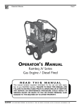
Operator’s Manual
EH SERIES
Gas Engine / Diesel Fired
READ
THIS
MANUAL
This manual contains important information for the use and safe operation
of your RAMTEQ machine. FAILURE TO READ THIS MANUAL AND
FOLLOW ITS INSTRUCTIONS PRIOR TO OPERATING OR ATTEMPTING
ANY SERVICE OR MAINTENANCE PROCEDURE COULD RESULT IN
SERIOUS INJURY OR DEATH TO YOU OR OTHER PERSONS; ALSO
DAMAGE TO THE MACHINE OR TO OTHER PROPERTY.
®
AMAZING MACHINERY
2288 Gunbarrel
Suite 111-151
RAMTEQ
14275 northwest
freeway Road,
Houston,
TX
®
Chattanooga,
37421 fax:
Phone:
1-800-504-7435 Fax: 1-800-504-7436
77040
phone:TENNESSEE
713.983.6000
713.983.6405 300-00003-2
7/07
Operator’s Manual
Page
Table of Contents
Operator’s Manual
Unpacking....................................................................2
Safety Instructions and Warnings.............................3
Maintenance Instructions.......................................4, 5
Operating Instructions...............................................6
Section 1
Section 2 Parts
and
Service Manual
Exploded View..............................................................7
Parts List.....................................................................8
Burner Assembly (12V)................................................9
Burner Assembly (115V).............................................10
Control Box Assemblies.............................................11
Engines & Mufflers and Hose, Wand, & Gun.............12
Belt Driven Pumps......................................................13
Wiring Diagrams....................................................14, 15
Plumbing Diagrams................................................16 - 19
Troubleshooting...........................................................20
Warranty.....................................................................21
Unpacking Instructions
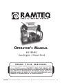
INSPECTION
Carefully unpack your new RAMTEQ equipment by removing the shrink
wrap & banding from pallet. Remove the pressure washer from the pallet and check for any physical damages that may have occurred during
shipment. Check for all parts specified and shown in figure 1. Included Parts
• Pallet
• Packing Material
Outer Box
• EH Series Machine
• Operator’s Manual
• Wand / Trigger Gun
• Nozzles 15º
• Hose 3/8” X 50’
NOTICE
Information in this operator’s manual is subject to change without notice. RAMTEQ SHALL NOT BE LIABLE FOR TECHNICAL OR EDITORIAL ERRORS OR OMISSIONS CONTAINED HEREIN. This operator’s manual
contains information protected by copyright. No part of this operator’s manual may be photocopied or reproduced in any form without
prior written consent from RAMTEQ.
© RAMTEQ, 2006
All rights reserved. Printed in USA.
RAMTEQ
®
14275 northwest freeway
Houston, TX 77040
phone: 713.983.6000
fax: 713.983.6405 300-00003-02
7/07
Operator’s Manual
Page Safety Guidelines
�
WARNING
READ THIS FIRST! Failure to read and observe all
WARNING statements could result in severe bodily injury or death, possible injury to other persons,
damage to machine or other property.
DO NOT operate this machine in areas where open flames are not permitted. DO NOT store or
use combustible materials on or near this machine. Use this equipment only in well ventilated
areas. Failure to follow this warning may cause carbon monoxide build up, fire or explosion, and
possible injury or death.
DO NOT fill gasoline tank while engine is running. Allow engine to cool before refueling. Should
gasoline be spilled, move the machine away from the area of the spill. Do not attempt to restart
the machine until the gasoline has fully evaporated.
DO NOT operate engine if air cleaner or cover directly over the carburetor air intake is removed.
DO NOT touch hot mufflers, cylinders or fins, as contact may cause burns
DO NOT operate this machine while under the influence of alcohol, drugs or while fatigued.
DO NOT direct discharge stream at yourself or others. Risk of injection or injury may occur.
Never put your hand or fingers over the spray tip. Do not try to stop or deflect leaks with your hand or body. Always face nozzle and wand to the ground when testing.
DO NOT operate this machine without wearing protective Eye Wear. Gloves, Hard Hat, Mask, Ear Plugs & Steel Toe Work Boots are also recommended, DO NOT wear loose clothing. Keep
your body and clothing clear of the engine and discharge stream when the machine is running.
DO NOT tie back or block trigger gun in OPEN position. Never leave the pressure washer
unattended once you have started it. If you leave, shut down machine completely.
DO NOT overreach or stand on an unstable support while operating this machine. Maintain
good footing and balance.
DO NOT permit this machine to run while unattended or for extended periods of time with
trigger gun closed. Damage to pump may occur.
DO NOT operate this machine in an unsafe manner or around unsupervised children. Keep all
other personnel clear while operating this machine. This product should only be operated by
trained personnel.
DO NOT alter original factory settings prior to operating this machine. Risk of injury to yourself or
other persons may occur.
DO NOT remove hoses, guns, nozzles or any components while this machine is still hot or while
it is running.
DO NOT attempt to service this machine before reading the service manual.
DO NOT use water with a temperature over 140 degrees FareEHeit
DO NOT put diesel fuel in to a gasoline tank or gasoline into a diesel tank. Observe correct
markings on fuel tanks before filling.
DO NOT operate this machine without knowing how to stop and bleed water pressures. Know all
controls before using this machine.
DO NOT spray caustic, acids or abrasive fluids through this machine.
DO NOT permit water to freeze inside this machine. Pump and plumbing damage may occur.
Use only recommended RAMTEQ™ parts when servicing this machine.
RAMTEQ™ will not be held liable for any unauthorized modifications made to this
machine. Any such action will void the warranty.
When connecting battery, ensure that the RED battery cable is connected to the POSITIVE pole
on the battery and the BLACK is connected to the NEGATIVE pole on the battery
RAMTEQ
®
14275 northwest freeway
Houston, TX 77040
phone: 713.983.6000
fax: 713.983.6405 300-00003-02
7/07
Operator’s Manual
Page Maintenance Instructions
MAINTENANCE PRECAUTIONS
Do not permit acidic, caustic or abrasive fluids to be pumped through system.
Periodically clean detergent inlet screen. This will ensure proper flow of water to the pump.
High mineral content in water may adversely affect your machine and may require the use of a water softener
to ensure proper operation.
NEVER run the pump dry under any circumtances. Doing so will cause exteme damage to the pump.
�
FAILURE TO MAINTAIN HEAT EXCHANGER COIL MAY
RESULT IN A STEAM EXPLOSION WHICH MAY CAUSE
SERIOUS INJURY OR DEATH.
WARNING
HEAT EXCHANGER COIL MAINTENANCE
Hard water conditions may eventually cause clogging in the heat exchanger coil if left unattended. Scale deposits will compromise the heating efficiency and produce an unsafe condition over time. It may be necessary to descale coil.
Scale buildup from certain detergents may eventually clog up the heat exchanger coil causing an
unsafe condition. Use only recommended detergents for better cleaning efficiency. Black carbon deposits that collect on the outside wall of the heat exchanger coil may be a result of
using a poor grade of fuel or improper burner operation. Heating fuel should be void of water and
sediments to eliminate the possibility of sooting and compromising the efficiency of the coil.
MOVING, STORAGE
Place machine in covered area when not in use to protect from elements.Protect machine from
freezing in cold temperatures by storing in a heated location.
ENGINE MAINTENANCE
Every time (before start): Check oil level.
First 8 hours: Change oil with SAE 30W High-Detergent Oil.
Every 25 hours: Change oil if operating under heavy load or high ambient temperature.
Service air cleaner pre-cleaner.
Every 50 hours: Change oil. Clean and inspect spark arrester if equipped.
Every 100 hours: Service air cleaner cartridge, replace oil filter (if equipped),
Clean oil cooler (if equipped), Clean cooling system.
WINTERIZING
Non-float Tank Machines: To protect the machine from freezing temperatures while
storing or transporting, connect short length of garden hose (approximately 3 ft.) to
water inlet connection on machine. Remove the pressure nozzle from the wand and
insert the short garden hose end into a container of antifreeze. Place the wand into the
antifreeze container and start engine running machine until antifreeze appears from the
end of the wand. Turn engine “OFF” and replace pressure nozzle. Coil up hose and
move machine to storage area.
RAMTEQ
®
14275 northwest freeway
Houston, TX 77040
phone: 713.983.6000
fax: 713.983.6405 300-00003-02
7/07
Operator’s Manual
Page Maintenance Instructions
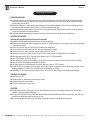
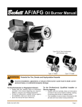
ELECTRODE SETTINGS
Inspection of all wires, spring contacts
and electrodes should be done periodically. Wayne Burner
�
WARNING
Beckett Burner
IF BLACK OR WHITE SMOKE VENTS FROM EXHAUST
PORT UPON STARTING EQUIPMENT, DISCONTINUE USE
AND ADJUST AIR BANDS BEFORE RESTARTING.
OIL BURNER AIR BAND ADJUSTMENT
RAMTEQ sets oil burners at sea level. Air bands may need adjustment at higher elevations to
offer eEHanced performance of the burner and extended life of the machine. ®
Adjustment of burner is done with pump motor and thermostat
set to maximum. Loosen locking screw on air band, then close
band until black smoke vents up exhaust vent. Take careful note
of air band position when black smoke is first noticed. Slowly
open air band until white smoke vents, then turn air band halfway
back to where black smoke was first noted. Tighten air band
locking screw. When properly set, the unit should NOT have either
"black" smoke or "white" smoke during operation.
PUMP MAINTENANCE
Fill crankcase to dot on oil gauge window per specifications with the specific oil created by the
pump manufacturer (i.e. General Pump Oil). Ensure the right oil for specific pump as it may vary.
Change oil after 25 Hour Break-in Period.
Change oil every Three Months or at 100 Hour Intervals thereafter.
UNLOADER ADJUSTMENT
All RAMTEQ machines have the unloader correctly set at the the factory. Setting an unloader
is a difficult job without the proper equipment and training. Should the need arise to change the unloader
settings, please contact your local distributor.
RAMTEQ
®
14275 northwest freeway
Houston, TX 77040
phone: 713.983.6000
fax: 713.983.6405 300-00003-02
7/07
Operator’s Manual
Page Operating Instructions
LOCATION GUIDELINES
Locate the machine on a solid and level surface so that engine and pump crankcase oil lubricate components properly.
Avoid areas where water can build up in the working area. Possible injury can occur caused by the surface becoming
slippery from water build up.
Locate the machine in a well-ventilated area and away from flammable materials or fumes. Be sure ventilation warnings
are observed. Keep pressure washer at least 18” away from flamable materials.
Locate the machine so the operator has easy access to the jetter/pressure washer and its controls. Locate the machine
so that it is protected from external damage.
To prevent damage and excessive hose wear, locate the unit so that the hose does not cross traffic areas.
STARTING THE MACHINE
Following the steps below will insure successful operation:
Read this manual completely before attempting to start the machine.
Check the fuel tank and fill with a good grade of gasoline (87 octane minimum) for gas engines and a high quality diesel
fuel for diesel engines.
Check the engine oil level and fill with SAE 30 weight high-detergent oil.
Check the pump oil level and fill with SAE 30w non-detergent oil if needed.
Check water tank to ensure adequate level of water required for the job.
Pull trigger on gun until a steady stream of water comes out the nozzle. This purges any air in the system.
Slide fuel switch to the RIGHT and slide choke switch to the LEFT (closed position).
Turn ON/OFF switch (on engine) to “ON”.
Open water flow to reduce back pressure in pump. Back pressure can overpower electric starter, preventing ignition.
Turn key to start gas engine and allow RPM to develop.
Let engine warm up for approximately 30 seconds and slide choke to “OPEN” position.
Check for leaks in the system and cycle trigger gun to insure bypass is adjusted correctly. Repair any leaks and correct unloader adjustment if needed. Turn off machine before attempting any repairs.
WARNING - Do not operate machine with less than 6" of water in the tank. Doing so may cause pump damage!
STOPPING THE MACHINE
Turn engine to “OFF”.
Pull gun trigger to release water pressure from system.
Disconnect wand & gun assembly.
Wind up pressure hose on hose reel.
CAUTION
Always wear protective safety gear, auch as, but not limited to, rain coat or coveralls, rubber boots, face shield or
goggles, gloves and hearing protection.
Do not run the machine for more than two minutes with the jetter water flow shut off (by-pass mode). This will over
heat the jetter pump and could cause injury to you.
Do not run hot water thru this pump. Hot water will damage the pump, and will void the warranty.
RAMTEQ
®
14275 northwest freeway
Houston, TX 77040
phone: 713.983.6000
fax: 713.983.6405 300-00003-02
7/07
Operator’s Manual
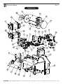
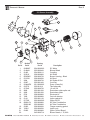
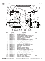
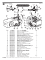
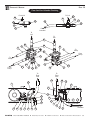
Page Exploded View
27
28
25
23
34
26
32
33
31
24
30
29
11
8
10
17
16
12
13
18
9
14
35
4
15 8
19
2
3
7
5
36
37
45
22
6
20
21
39
46
40
45
41
42
43
RAMTEQ
®
44
14275 northwest freeway
38
1
Houston, TX 77040
phone: 713.983.6000
fax: 713.983.6405 300-00003-02
7/07
Operator’s Manual
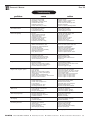
Page Parts List
Ref.#
Part #
Description
Qty.
1
180-00319-01
Frame, EH
1
2
180-00320-01
Plate, Power, EH
1
3
See Pg 12
Engines (Honda, Vangaurd, Kohler, Yanmar)
1
4
See Pg 12
Muffler Assys (Honda, Vangaurd, Kohler)
1
5
See Pg 13 Pumps (General, Comet)
1
6
584-00002-52
Pulley, SST#2BK90H /2MBL87
1
7
516-00002-21
Bushing, SP, split taper, SST#H-24MM /L-24
1
8
584-00003-21
Pulley, SST#2B34SH /2B34
1
9
516-00003-21
Bushing, SP, split taper, SST#SH-1"
1
10
586-00004-11
Belt, BX43
2
11
180-00321-01
Belt guard, EH 1
12
216-00002-01
Generator, Winco, 2FSM2PC-1
1
13
180-00246-01
Adapter, belt guard, Winco
1
14
584-00002-19
Pulley, Maska #MB35 X 5/8, SST #BK 34 X 5/8
1
15
584-00003-31
Pulley, SST#3B34SH / 3B34
1
16
586-00004-01
Belt, BX22
1
17
180-00172-01
Generator Belt Guard, CH/DV
1
18
180-00321-02
Belt guard, w/generator cut out, EH 1
19
180-00269-01
Generator plate, EH
1
20
590-00001-01
Box, Battery, vented, black, w/hdwe
1
21
190-00003-01
Tank, float, base
1
22
190-00003-02
Tank, float, lid
1
23
155-00009-01
Coil, large, diesel fired, horiz, EH
1
24
180-00255-01
Shell, SS, bottom, EH
1
25
180-00256-01
Shell, SS, top, EH
1
26
180-00253-01
End cap, CH Lite, round
1
27
180-00254-02
Burner cap, EH, flat, w/holes
1
28
See Pg 9 & 10
Burners (Beckett - 12V & 115V)
1
29
190-00001-02
Tank,fuel,10 gal,red,Ramteq
1
30
140-00002-01
Cap, fuel guage, gas, red, one way vent w/
1
31
190-00001-01
Tank, fuel, 10 gal, green, Ramteq
1
32
140-00001-01
Cap, fuel guage, diesel, black, one way vent
1
33
180-00135-01
Heat Reflector, CH, 1 tank
1
34
180-00261-01
Torsion rod, dual fuel tank
2
35
180-00175-01
Strap, Tank Torsion, 304SS, 3 ga. .244"
2
36
055-00070-01
Control Box (EH)
1
37
180-00141-01
Closeout panel, EH
1
38
180-00312-02
Panel, front closeout, skids, w/o pres gauge
1
39
180-00313-01
Bracket, for front closeout panel, skids
1
40
563-00001-01
Trim,black plastic
12.5 IN
41
055-00028-02
Control Box (CH upgrade)
1
42
180-00312-01
Panel, front closeout, skids, w/pres gauge
1
43
575-00003-01
Pressure gauge, Panel Mount
1
44
576-00002-01
Mounting Bracket, for U-Clamp
1
45
180-00360-01
Cord Holder, for EH Special
1 or 2
46
180-00395-01
Bracket, for EH Frame
2
RAMTEQ
®
14275 northwest freeway
Houston, TX 77040
phone: 713.983.6000
fax: 713.983.6405 300-00003-02
7/07
Operator’s Manual
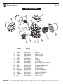
Page 12v Burner Assembly
20
19
18
21
17
22
15
14
16
13
10
11
12
1
2
3
4
5
6
9
8
7
Beckett
Ref.#
Part #
1
21699UF
2
2140401
3
21405
4
31231U
5
5874BKU
6
5151501
7
3494
8
21807
9
218440ZU
10 21877U
11 21754U
12 3666
13 3493
14 5700
15 7492
16 51411
17 51776U
18 58020174
58020198
19 31802
20 7435U
21 51663
22
RAMTEQ
®
14275 northwest freeway
Ramteq
Part #
254-00002-02
253-00004-01
254-00001-11
259-00006-01
259-00007-01
259-00005-01
259-00007-01
252-00014-01
251-00002-03
252-0010-01
252-00007-01
252-00013-01
252-00012-01
258-00006-01
252-00009-01
252-00011-01
252-00005-02
253-00008-01
253-00009-01
256-00002-01
252-00005-01
252-00006-01
245-00007-14
Houston, TX 77040
Description
DC Motor
Blower Wheel
Coupling
Air Guide
Burner Housing - Black
Air Band
Air Shutter 8 Slot
Cord Set
Pump (CleanCut)
Tube assembly
12 volt Coil
Escutcheon plate spline nut
Escutcheon plate
Electrode kit
Cad cell detector
Ignitor gasket kit
Ignitor w/ICB
Air Tube Combination
Air Tube Combination
Flange mounting gasket
Ignitor only
Ignitor Control Board
Burner Nozzle, 1.75, 90A
phone: 713.983.6000
fax: 713.983.6405 300-00003-02
7/07
Operator’s Manual
Page 10
115V Burner Assembly
12
13
14
5
16
10
15
11
4
7
8
6
2
9
Beckett
Ramteq
Ref.#
Part #
Part #
1
5348BK
259-00010-01
2
3215
259-00009-01
3
3819A
259-00005-02
4
3493
252-00012-01
5
323003
253-00005-01
6
2433
254-00001-12
7
2900U
254-00002-01
8
2383
253-00004-02
9
21844
251-00002-05
10 5394
252-00010-02
11 3666
252-00013-01
12 7441
252-00005-05
13 SM35VMDC 253-00007-01
14 5153508BK 253-00006-01
15 21807
252-00014-01
16 21566214
245-00007-16
Not Shown F22
260-00008-03
RAMTEQ
®
14275 northwest freeway
Houston, TX 77040
3
1
Description
Housing
Shutter 10 Slot
Air Band 10 Slot
Escutcheon Plate
Flange
Coupling
1/5 HP Motor
6-1/4 X 3-7/16 Blower Wheel
Pump w/ Coil
Connector Tube Assembly
3/8 Spline Nut
Ignitor Assembly
Air Tube Combination
Air Tube Double Flange
Cordset Non Delay 16"
Nozzle, 2.25, 90A
Air Cone, F22
phone: 713.983.6000
fax: 713.983.6405 300-00003-02
7/07
Operator’s Manual
Page 11
5
Control Box Assemblies
6
4
7
Base Control Box
3
Ref.#
Part #
1 2
3
4
5
6
7
180-00027-01
305-00038-01
571-00002-01
450-00004-01
457-00001-01
455-00002-01
455-00001-01
Description
Qty.
Control Box Label, Control Box Meter, Hour
Switch, Toggle, NKK#S301F
Boot, switch, water prrof, NKK#AT402
Relay,12V, VF441F11
Rectifier, GBPC2506
2
1
1
1
1
1
1
1
1
7
5
8
9
4
3
CH Upgrade Control Box
2
6
Ref.#
Part #
1 2
3
4 5
6
7
8
9
180-00027-01
180-00027-01
305-00040-02
571-00002-01
450-00001-01
573-00001-01
508-00002-01
513-00008-01
505-00001-01
RAMTEQ
®
Description
1
Qty.
Control Box, Universal
1
Control panel, small, 2 rocker, therm, hr 1
Label, burner only control, XV
1
Hourmeter
1
Switch, rocker, low-amp
1
Thermostat, 194 degree, 100438
1
Nut, SP, Cage, 1/4-20,.064-.105
2
Washer, SS, Plain, 1/4, narrow
2
Bolt, SS, Hex, 1/4-20, .5"
2
14275 northwest freeway
Houston, TX 77040
phone: 713.983.6000
fax: 713.983.6405 300-00003-02
7/07
Operator’s Manual
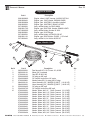
Page 12
Engines & Mufflers
Part #
206-00028-03
206-00004-01
206-00006-04
206-00023-01
207-00002-01
206-00017-02
207-00003-02
206-00029-01
207-00005-01
206-00011-01
207-00004-01
Description
Engine, diesel, 10HP, Yanmar, L100V6CA1T1AA
Engine, gas, 13HP, Honda, GX390U1QNR2
Engine, gas, 16HP, B&S, w/muffler installed
Engine, gas, 18HP, B&S, 350447-1075-E1
Assy, muffler/shield, for B&S 16&20
Engine, gas, 20HP 20A, Honda, GX620U1QAF1
Assy, muffler/shield, Honda 16 & 20
Engine, gas, 21HP, Briggs
Assy, muffler/shield, for B&S 21/23 HP
Engine, gas, 25HP, Kohler, CH25S, 1 1/8" shaft
Assy, muffler kit, for Kohler 20/25 HP
Hose, Wand & Gun
10
2
5
6
9
1
8
Ref.#
1
2
3
4
5
6
7
8
9
10
RAMTEQ
®
Part #
265-00002-01 265-00001-01
275-00001-01
552-00003-03
554-00006-02
270-00038-01
284-00001-01
284-00002-01
552-00004-03
554-00007-03
270-00002-01
270-00002-02
270-00002-03
270-00002-04
270-00005-01
270-00005-02
270-00005-03
270-00005-04
270-00004-01
270-00004-02
270-00004-03
270-00004-04
14275 northwest freeway
7
4
3
Description
Qty.
Dual lance,8107-1101,Comet 15*,43"SS 1
Wand, 36", insulated
1
Gun,BE, 85.202.108
1
QC plug,sp,3/8",nptf
1
QC coupler socket,brs,1/4",nptm
1
Nozzle,water,SS,1/4, soap,#40,15 degr
1
Hose Assembly, 50’, 3000PSI @ 250°F (10-16 HP)
Hose Assembly, 50’, 5000PSI @ 250°F (18-25 HP)
QC plug,sp,3/8",nptf
1
QC coupler socket,brs,3/8",nptf
1
Nozzle, Water, #4.0, 0° Quick Connect (10,13 HP)
Nozzle, Water, #4.0, 15° Quick Connect (10,13 HP)
Nozzle, Water, #4.0, 25° Quick Connect (10,13 HP)
Nozzle, Water, #4.0, 40° Quick Connect (10,13 HP)
Nozzle, Water, #5.5, 0° Quick Connect (16-21 HP)
Nozzle, Water, #5.5, 15° Quick Connect (16-21 HP)
Nozzle, Water, #5.5, 25° Quick Connect (16-21 HP)
Nozzle, Water, #5.5, 40° Quick Connect (16-21 HP)
Nozzle, Water, #5.0, 0° Quick Connect (20-25 HP)
Nozzle, Water, #5.0, 15° Quick Connect (20-25 HP)
Nozzle, Water, #5.0, 25° Quick Connect (20-25 HP)
Nozzle, Water, #5.0, 40° Quick Connect (20-25 HP)
Houston, TX 77040
phone: 713.983.6000
fax: 713.983.6405 300-00003-02
7/07
Operator’s Manual
Page 13
1
Belt Drive Pumps
2
General Pump TS2021-R Triplex Plunger Pump
Pump Repair Parts
Ref#
1.
2.
Part#
220-00009-01
221-00001-03
Pump Repair Kits (not shown)
221-00021-01
221-00020-01
221-00019-01
221-00023-01
221-00031-01
Description
Pump, Complete, General TS2021-R
Manifold, Brass Head TS2021
Qty
1
1
Check Valve Assembly Kit #1 (6 Each)
(3 Oil Seals)
Oil Seals, Kit #2 (6 Each)
Valve Cap and O-Ring, Kit #16
(3 Each)
V-Packing, Kit #69 Piston/Plunger, 20MM
1
1
1
1
3
General Pump TS1511 & T9211Triplex Plunger Pump
Pump Repair Parts
Ref#
1a.
1b.
2a.
2b.
Part#
220-00053-01
220-00103-01
contact ramteq
contact ramteq
Pump Repair Kits (not shown)
221-00002-01
221-00018-01
221-00072-01
221-00081-01
221-00029-01
221-00031-01
Description
Pump, Complete, General TS1511
Pump, Complete, General T9211
Manifold, Brass Head TS1511
Manifold, Brass Head T9211
Qty
1
1
1
1
Check Valve Assembly Kit #1 (6 Each)
(3 Oil Seals)
Oil Seals, Kit #2 O-Ring for Valve Cap Kit
(6 Each)
Brass Valve Cap Kit (6 Each)
(3 Each)
V-Packing, Kit #69 Piston/Plunger, 20MM
1
1
1
1
1
3
General Pump T9821 Triplex Plunger Pump
Pump Repair Parts
Ref#
1.
2.
Part#
220-00008-01
contact ramteq
Pump Repair Kits (not shown)
221-00002-01
221-00018-01
221-00025-01
221-00029-01
221-00044-01
Description
Pump, Complete, General T9821
Manifold, Brass Head T9821
Qty
1
1
Check Valve Assembly Kit #1 (6 Each)
(3 Oil Seals)
Oil Seals, Kit #2 (6 Each)
Valve Cap and O-Ring, Kit #6
(3 Each)
V-Packing, Kit #69 Piston/Plunger, 20MM
1
1
1
1
3
1
2
Comet SW5540 Triplex Plunger Pump
Pump Repair Parts
Ref#
1.
2.
Part#
220-00099-01
contact ramteq
Pump Repair Kits (not shown)
RAMTEQ
®
221-00021-01
221-00020-01
221-00023-01
14275 northwest freeway
Description
Pump, Complete, Comet SW5540
Manifold, Brass Head SW5540
Qty
1
1
Check Valve Kit (6 Each)
Complete Oil Seals, O-Ring Kit
Packing Kit
(3 Each)
1
1
1
Houston, TX 77040
phone: 713.983.6000
fax: 713.983.6405 300-00003-02
7/07
Operator’s Manual
Page 14
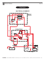
Wiring Diagram
ELECTRICAL SCHEMATIC
“Small” Blk
Wht
Red
Blower
“Big” Red
Ylw
- N.O.
+
Ylw
Burner
Module
Blk
Blk
Ignitor
Transformer
Org
Wht
Fuel
Solenoid
Dropout
Timer
Ylw
Photocell
“Small” Red
Red
Wht
Blk
Control Panel
Blk
Red
AC
BURNER SW
Wht
AC
+
Red
Blk
Red
Blk
Wht
Blk
87
Wht
86
85
1
P1
Red
30
THERMOSTAT
Red
Red
Brn
Red
Blk
Grn
Wht
FLOW SWITCH or
PRESSURE SWITCH
Battery
12 Volt
Starter
Solenoid
Blk
Alternator
Gas Engine
RAMTEQ
®
14275 northwest freeway
Houston, TX 77040
phone: 713.983.6000
fax: 713.983.6405 300-00003-02
7/07
Operator’s Manual
Page 15
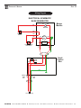
Wiring Diagram
ELECTRICAL SCHEMATIC
EH W/ GENERATOR
Pur
Blk
Burner
Module
Wht
Fuel
Solenoid
Wht
PRESSURE
SWITCH
Wht
Blk
Org
Burner
Mtr
Wht
Blk
Wht
HI-TEMPERATURE
LIMIT SWITCH
HOURMETER
Grn
BURNER
SWITCH
Blk
Grn
Blk Transformer Blk
for Ignitor
N.C.
Small
Control
Box
Wht
Grn
SMOOTH
WIRE
(Blk)
RIBBED
WIRE
(Wht)
115v Rt Angle Plug
RAMTEQ
®
14275 northwest freeway
Houston, TX 77040
phone: 713.983.6000
fax: 713.983.6405 300-00003-02
7/07
Operator’s Manual
Page 16
From Coil
18
22
Down Stream Injection Plumbing
14
19
To Coil
15
14
From
Pump
17
23
24
16
5
20
To Coil
13
21
16
8
7
5
1
1
7
9
12
11
6
Ref.#
1
2
3
4
5
6
7
8
9
10
11
12
13
14
15
16
17
18
19
20
21
22
23
24
Not Shown
Not Shown
RAMTEQ
®
5
Part #
See Page 13
538-00007-01
522-00010-01
522-00002-03
557-00001-01
280-00002-03
530-00003-04
230-00011-02
536-00003-02
528-00002-01
517-00002-01
574-00002-01
284-00010-06
524-00013-02
536-00006-05
517-00003-02
569-00003-10
536-00003-03
450-00014-01
543-00004-04
567-00010-01
528-00003-01
554-00006-03
579-00004-03
285-00002-01
570-00002-01
14275 northwest freeway
4
2
10
3
3
2
Description
Pumps (General, Comet)
Tee, branch, brs, 1/2npt
Conn, Gar. Hose, 3/4 swivel X 1/2 nptm, close
Conn, hose end, brs, 1/2nptm X 3/8 barb
Hose Clamp, ss, 0.25"-0.63" diameter
Hose, low pressure, 1/2"
Elbow, brs, 3/8nptm X 3/8 barb, 90 degrees
Unloader, Pulsar#3HP, without knob
Tee, Street, sp, 3/8nptf X 3/8nptm X 3/8nptf
Elbow, sp, 3/8nptf X 3/8nptm, 90 degrees
Bushing, SP, 3/8 nptm X 14/nptf
Pressure switch, GP#YPRESSWITCH
Hose Assy, 48"L, 3/8", 4000PSI@250F, High
Nipple, sch. 80, 1/2" X 3", galvanized
Tee, sp, 1/2"
Bushing, sp, 1/2 nptm X 3/8 nptf
Valve, pop-off, 5000 psi, #22533A
Tee, street, sp, 1/2 nptf X 1/2 nptm X 1/2 nptf
Switch, thermal hi-limit, 210 deg., 3/8 X 1/2
Coupling, PVC, 1/2 FPT X 1/2 FPT
Bushing, str wire, 230-.546, 1/2, Heyco #3200
Elbow, sp, 1/2 nptf X 3/8 nptf, 90 degrees
QC coupler socket, brs, 3/8" nptm
Injector, detergent, GP 100577 5-8 gpm
Tubing, clear, 1/4" ID, 3/8"OD Check valve, plastic, .25", w/screen
Houston, TX 77040
phone: 713.983.6000
Qty.
1
1
1
1
2
17 in
1
1
1
1
1
1
1
2
1
3
1
1
1
1
1
1
1
1
48 in
1
fax: 713.983.6405 300-00003-02
7/07
Operator’s Manual
Page 17
From Coil
To Coil
Up Stream Injection Plumbing
22
22
24
29
26
27
23
10
24
25
To Coil
28
10
From
Pump
9
14
1
To
Float
Tank
To Coil
13
To
Float
Tank
11
12
7
8
17
16
18
Ref.#
1
2
3
4
5
6
7
8
9
10
11
12
13
14
15
16
17
18
19
20
21
22
23
24
25
26
27
28
29
Not Shown
Not Shown
RAMTEQ
®
Part #
See Page 13
524-00009-01
550-00004-01
530-00004-01
281-00002-02
280-00002-02
557-00001-01
530-00003-04
230-00011-02
284-00010-06
536-00003-02
528-00002-01
517-00002-01
574-00002-01
582-00003-03
524-00003-01
579-00006-01
522-00001-01
530-00004-09
557-00001-03
280-00002-04
524-00013-02
536-00006-05
517-00003-02
569-00003-10
185-00001-01
518-00004-01
554-00006-03
573-00001-01
285-00002-01
570-00002-01
14275 northwest freeway
15
6
21
2
5
4
3
Description
Pumps (General, Comet)
Nipple, sp, 1/2 nptm hex, close
Cross, brs, 1/2" FPT
Elbow, brs, JIC male X 1/2 nptm, 90 degrees
Swivel, brs, JIC female X 3/8 barb
Hose, low pressure, 3/8"
Hose Clamp, ss, 0.25"-0.63" diameter
Elbow, brs, 3/8 nptm X 3/8 barb, 90 degrees
Unloader, Pulsar #3HP, without knob
Hose assy, 48"L, 3/8", 4000 psi @ 250 F
Tee, street, sp, 3/8 nptf X 3/8 nptm X 3/8 nptf
Elbow, sp, 3/8 nptf X 3/8 nptm, 90 degrees
Bushing, sp, 3/8 nptm X 1/4 nptf
Pressure switch, GP#YPRESSWITCH
Bushing, brs, 1/2 X 3/8
Nipple, hex, sp, 3/8 nptm X 1/4 nptm
Valve, metering
Conn, hose end, 1/4 nptm X 1/4 barb
Elbow, brs, 1/2 nptm X 5/8 barb, 90 degrees
Hose Clamp, ss, #12
Hose, low pressure, 5/8" ID
Nipple, sch. 80, 1/2" X 3", galvanized
Tee, sp, 1/2"
Bushing, sp, 1/2 nptm X 3/8 nptf
Valve, pop-off, 5000 psi, #22533A
Manifold, outlet
Plug, brs, 3/8
QC coupler socket, brs, 3/8" nptm
Thermostat, 194 degrees, 100438
Tubing, clear, 1/4" ID, 3/8"OD Check valve,plastic,.25",w/screen
Houston, TX 77040
phone: 713.983.6000
19
20
Qty.
1
1
1
1
1
17 in
1
1
1
1
1
1
1
1
1
1
1
1
1
1
42 in
2
1
2
1
1
1
1
1
48 in
1
fax: 713.983.6405 300-00003-02
7/07
Operator’s Manual
Page 18
Flow Sensitive Unloader Plumbing
From Coil
To Coil
33
33
31
38
35
32
26
31
34
36
37
From
Unloader
To
Coil
To
Coil
27
6
30
29
26
30
6
To
Pump
25
From
Pump
24
To
Pump
20
17
From
Pump
29
28
21 22 23
18
19
To
Float
Tank
To
Float
Tank
16
16
1
17
15
14
2
17
13
4
12
5
11
6
10
RAMTEQ
®
9
8
7
3
14275 northwest freeway
3
4
11 12
Houston, TX 77040
phone: 713.983.6000
From
Unloader
5
6
To
Unloader
fax: 713.983.6405 300-00003-02
7/07
Operator’s Manual
Page 19
Flow Sensitive Unloader Parts List
Ref.#
1
2
3
4
5
6
7
8
9
10
11
12
13
14
15
16
17
18
19
20
21
22
23
24
25
26
27
28
29
30
31
32
33
34
35
36
37
38
Not Shown
Not Shown
RAMTEQ
®
Part #
See Page 13
524-00009-01
550-00004-01
530-00004-04
557-00001-02
280-00002-03
582-00003-03
524-00003-01
579-00006-01
522-00001-01
530-00004-09
557-00001-03
280-00002-04
536-00003-02
517-00002-01
574-00002-01
284-00010-05
528-00002-02
185-00002-01
504-00001-07
513-00008-01
512-00003-01
508-00001-01
524-00003-02
230-00015-03
540-00003-01
284-00010-09
518-00001-01
530-00003-02
281-00002-02
517-00003-02
536-00006-05
524-00013-02
569-00003-10
185-00001-01
518-00004-01
554-00006-03
573-00001-01
285-00002-01
570-00002-01
14275 northwest freeway
Description
Qty.
Pumps (General, Comet)
1
Nipple, sp, 1/2 nptm hex, close
1
Cross, brs, 1/2" FPT
1
Elbow, brs, 1/2 nptm X 1/2 barb, 90 degrees
1
Hose Clamp, ss, 0.40"-0.90" dia.
1
Hose, low pressure, 1/2"
32 in
Bushing, brs, 1/2 X 3/8
1
Nipple, hex, sp, 3/8 nptm X 1/4 nptm
1
Valve, metering
1
Conn, hose end, 1/4 nptm X 1/4 barb
1
Elbow, brs, 1/2 nptm X 5/8 barb, 90 degrees
1
Hose Clamp, ss, #12
2
Hose, low pressure, 5/8" ID
43 in
Tee, street, sp, 3/8 nptf X 3/8 nptm X 3/8 nptf
1
Bushing, sp, 3/8 nptm X 1/4 nptf
1
Pressure switch, GP#YPRESSWITCH
1
Hose assy, 36"L, 3/8", 4000 psi @ 250F, high
1
Elbow, street, sp, 3/8 nptm X 3/8 nptf, 90 degrees 1
Manifold, unloader
1
Bolt, sp, hex, 1/4-20 X 2"L
2
Washer, sp, flat, 1/4 SAE
4
Washer, sp, Hel Sprg Lk, 5/16, SAE
2
Nut, SP, Hex, 1/4-20
2
Nipple, sp, 3/8 nptm X 1/2 nptm
1
Unloader, K7.2, 3.2-6.6 GPM
1
Coupler, sp, 3/8 nptf X 3/8 nptf
1
Hose assy, 23"L, 3/8", 4000 psi @ 250F, high
1
Plug, brs, 1/4 nptm, hex
1
Elbow, brs, 3/8 nptm X #8 JIC male, 90 degrees
1
Swivel, brs, #8jic fem x 3/8 barb
1
Bushing, sp, 1/2 nptm X 3/8 nptf
2
Tee, sp, 1/2"
1
Nipple, sch. 80, 1/2" X 3", galvanized
2
Valve, pop-off, 5000 psi, #22533A
1
Manifold, outlet
1
Plug, brs, 3/8
1
QC coupler socket, brs, 3/8" nptm
1
Thermostat, 194 degrees, 100438
1
Tubing, clear, 1/4" ID, 3/8"OD 48 in
Check valve,plastic,.25",w/screen
1
Houston, TX 77040
phone: 713.983.6000
fax: 713.983.6405 300-00003-02
7/07
Operator’s Manual
Page 20
troubleshooting
problem
Low Water Pressure
cause
action
Insufficient water source
Old or incorrect nozzle
Plumbing or hose leak
Obstruction in spray nozzle
Chemical valve open
Unloader valve worn
Pump valves dir ty or worn
Check hose size/water source
Replace nozzle
Tighten, repair or replace leak
Clean or replace nozzle
Close valve or submerge hose
Replace unloader
Clean or replace packing/valves
Detergent valve closed
Low detergent level
Chemical screen dir ty
Open detergent valve
Fill detergent container
Clean detergent screen
Fill fuel tank with proper fuel
Turn burner switch on
Reset thermostat
Replace fuel filter
Replace pressure switch
Replace burner nozzle
Replace fuel pump
Clean/reset to specifications
No Chemical Flow Burner Not Igniting
No fuel Burner switch turned off
Thermostat set too low
Clogged fuel filter Defective pressure switch
Clogged burner nozzle
Fuel pump malfunction
Improper electrode setting
Excessive Burner Smoke
Improper fuel being used
Water contamination in fuel Improper air band adjustment
Low fuel pressure Air leaks in fuel lines
Soot on coils/burner assembly
Misaligned electrodes
Dir ty burner nozzle
Use Diesel #1/#2 or Kerosene
Drain fuel and replace with new
Readjust air band/altitude
Adjust to specifications
Check for air leaks or bubbles
Clean coils/burner assembly
Realign to specifications
Clean or replace burner nozzle
Relief Valve Leaks Nozzle is dir ty
Defective relief valve
Unloader adjusted incorrectly
Restriction on discharge hose
Scale restricting flow in coil Clean or replace nozzle
Replace relief valve
Adjust unloader valve
Remove nozzle and flush line
Clean coil
Pressure
Engine Will Not Star t
Throttle lever off No fuel in engine Bad fuel or wrong fuel in engine
Worn, foul, or dir ty spark plug(s)
Pressure bulid up in pump Turn throttle lever to "on" position
Fill fuel tank if needed
Check to ensure correct fuel in tank
Check spark plugs
Squeeze trigger on gun
Engine runs rough/no power
Low oil level
Dir ty air filter
Bad fuel or wrong fuel in engine
Worn, foul, or dir ty spark plug(s)
Overchoking
Engine has lost compression
Intake valve stuck open or stuck closed
Incorrect fuel/air mixture
Check oil level, fill if needed
Check and replace air filter if needed
Check to ensure correct fuel in tank
Check spark plugs
Open choke fully and crank engine
Service engine at repair center
Service engine at repair center
Service engine at repair center
Pump Noisy
Air in suction line Pump valves dir ty Check valve springs worn
Low pump oil Pump bearings are worn
Incoming water too hot
Check inlet water fittings
Clean/replace pump valves
Replace check valves
Add SEA 30wt. non-detergent
Replace/rebuild pump
Reduce temperature/ambient
Water In Oil
High humidity environment Oil seal worn Plunger packing worn
Change oil frequently
Check and replace oil seal
Check and replace packing
Water Dripping/Pump
Plunger packing is worn
Plunger retainer oil ring worn Cracked ceramics Install new packing kit
Replace oil ring
Replace ceramics
Oil Dripping
Oil seal worn
Cracked manifold Check and replace oil seals
Replace manifold
Unloader not adjusted
Valves worn
Dir t or blockage in valves
Pump sucking air Worn plunger packing
Fluctuating Pressure
Pump Head Overheating RAMTEQ
®
14275 northwest freeway
Extended period in bypass Houston, TX 77040
Adjust to specifications
Replace with valve kit
Clean or replace valve
Check water/detergent supply
Replace packing kit
Pull trigger gun for water flow
phone: 713.983.6000
fax: 713.983.6405 300-00003-02
7/07
RAMTEQ
Limited One Year
WARRANTY
Ramteq Incorporated ("RAMTEQ") warrants that the Product you have purchased from RAMTEQ or from an
Authorized RAMTEQ Reseller is free from defects in materials or workmanship under normal use for a period of one
(1) year from the date of purchase. This warranty extends only to you, the original Purchaser. It is not transferable to anyone who subsequently purchases the Products from you. This warranty specifically excludes expendable
items, including but not limited to hoses, seals, nozzles and gunjets. RAMTEQ manufacturers warrant certain components of the Products for periods greater than one (1) year. MOTORS, GENERATORS, PUMPS, COILS, BURNERS
AND ENGINES ARE WARRANTED BY THEIR RESPECTIVE MANUFACTURERS, AND SERVICED THROUGH THESE
MANUFACTURERS' LOCAL AUTHORIZED SERVICE CENTERS. Specific warranty details can be found on the individual manufacturers website. RAMTEQ CANNOT PROVIDE WARRANTY ON THESE ITEMS.
During the warranty period, RAMTEQ will repair or replace defective parts, at the option of RAMTEQ.
This limited warranty does not extend to any Product not purchased from RAMTEQ or from an Authorized RAMTEQ
Reseller. This limited warranty also does not extend to any Product that has been damaged or rendered defective (a)
as a result of accident, misuse or abuse; (b) by operation outside the specifications in the intended applications; (c) by
the use of parts not sold or manufactured by RAMTEQ; (d) by the modification of the Product.
Warranty Disclaimer
EXCEPT AS EXPRESSLY SET FORTH IN THIS WARRANTY, RAMTEQ MAKES NO OTHER WARRANTIES, EXPRESS
OR IMPLIED, INCLUDING ANY IMPLIED WARRANTIES OF MERCHANTABILITY AND FITNESS FOR A PARTICULAR
PURPOSE. RAMTEQ EXPRESSLY DISCLAIMS ALL AND ANY WARRANTIES NOT STATED IN THIS LIMITED
WARRANTY. ANY IMPLIED WARRANTIES THAT MAY HAVE BEEN IMPOSED BY LAW ARE LIMITED TO THE TERMS
OF THIS EXPRESS LIMITED WARRANTY.
Limitation of Remedy
RAMTEQ IS NOT LIABLE FOR ANY DAMAGES CAUSED BY THE PRODUCT OR FAILURE OF THE PRODUCT TO
PERFORM, INCLUDING INCIDENTAL AND CONSEQUENTIAL DAMAGES. THIS LIMITATION APPLIES WHETHER
DAMAGES ARE SOUGHT, OR A CLAIM MADE, AS A CONTRACT CLAIM, AS A TORT CLAIM, OR ANY OTHER
CLAIM.
THIS LIMITATION OF LIABILITY, HOWEVER, WILL NOT APPLY FOR PERSONAL INJURY.
U.S.A. State Laws
Some states do not allow limitation on how long an implied warranty lasts. In such states, the limitations or
exclusions of this Limited Warranty may not apply to you.
Some states do not allow the exclusion or limitation in incidental or consequential damages for consumer products. In
such states, the exclusion may not apply to you. This limited warranty gives you specific legal rights. You may also
have other rights that may vary from state to state. You are advised to consult applicable state laws for a full
determination of your rights.
How to Obtain Warranty Service
TO OBTAIN WARRANTY SERVICE YOU MUST CONTACT RAMTEQ or an AUTHORIZED RAMTEQ RESELLER.
RAMTEQ
®
14275 NORTHWEST FREEWAY
HOUSTON, TX 77040
PHONE: 713.983.6000
FAX: 713.983.6405
300-00001-01
1/13
Ramteq
Manufacturers Warranty Period
Click on pictures to open manufacturers website.
5 years
5 years
3 years
3 years
3 years
3 years
18 months
18/36 months
Ramteq Pressure Washers
14275 NORTHWEST FREEWAY
HOUSTON, TX 77040
1 year
PHONE: 713.983.6000
FAX: 713.983.6405
1/13