1
Users Manual
Level 4
René Görlich, Michael Rudolph, and Dave Sandage
April 2006
Copyright © 2002-2006 by René Görlich
Table of Contents
1
2
3
Introduction............................................................................................................... 1
1.1
General Description ........................................................................................ 1
1.2
Features ........................................................................................................... 2
1.2.1
Physical Features .................................................................................... 2
1.2.2
Operational Features ............................................................................... 2
1.3
What’s New in Level 4? ................................................................................. 5
1.3.1
Gemini Supports Custom Mounts........................................................... 5
1.3.2
Supporting the Horizontal Coordinate System ....................................... 5
1.3.3
Selectable Serial Port Transmission Rates.............................................. 5
1.3.4
Selectable GPS transmission rate............................................................ 5
1.3.5
Reduced Main Menu selection available ................................................ 5
1.3.6
Redesigned Quick Menu selection.......................................................... 6
1.3.7
Parking the OTA ..................................................................................... 6
1.3.8
More Alignment Stars............................................................................. 6
1.3.9
Extended Serial Line Protocol ................................................................ 6
1.3.10
Extended Identify interface..................................................................... 6
1.3.11
Extended Safety Limits Handling........................................................... 6
1.3.12
Selectable PC Synchronization Behavior ............................................... 7
1.3.13
Precision Guiding Commands ................................................................ 7
Getting Started .......................................................................................................... 8
2.1
Quick Start Guide ........................................................................................... 8
2.2
Installation....................................................................................................... 9
2.2.1
Motor Installation.................................................................................... 9
2.2.2
Cable Installation .................................................................................... 9
2.2.3
Encoders................................................................................................ 10
2.2.4
Power Requirements ............................................................................. 11
2.3
Hand Controller Overview............................................................................ 11
2.3.1
Controls................................................................................................. 11
2.3.2
Menu Structure/Navigation................................................................... 12
2.3.3
QuickMenu ........................................................................................... 13
2.3.4
Moving the Mount Manually................................................................ 13
2.4
Basics of Operation....................................................................................... 14
2.4.1
Setting Up for Observing ...................................................................... 14
2.4.2
Power On and Setup.............................................................................. 15
2.4.3
Refining the Mount's Alignment Model ............................................... 19
2.4.4
Normal Operation ................................................................................. 22
2.5
Next Steps ..................................................................................................... 23
2.5.1
Gemini Users’ Group............................................................................ 23
Important Concepts about Your Mount............................................................... 24
3.1
Astronomical Coordinates ............................................................................ 24
3.1.1
Right Ascension and Declination.......................................................... 24
3.1.2
Precession ............................................................................................. 25
3.1.3
Azimuthal Coordinate System .............................................................. 25
3.2
How the Sky Moves...................................................................................... 26
Gemini Users Manual
i
4
5
3.3
Tracking ........................................................................................................ 26
3.3.1
Rates...................................................................................................... 26
3.3.2
Meridian Flip ........................................................................................ 32
3.3.3
RA Safety Limits .................................................................................. 32
3.3.4
GoTo Commands and Meridian Flips................................................... 33
3.4
Polar Alignment ............................................................................................ 34
3.4.1
Definition .............................................................................................. 34
3.4.2
Techniques ............................................................................................ 34
3.4.3
Accuracy Required................................................................................ 36
3.5
Mount Modeling ........................................................................................... 37
3.5.1
Definition .............................................................................................. 37
3.5.2
System Startup Modes .......................................................................... 37
3.5.3
Modeling Parameters ............................................................................ 39
Considerations for Imaging ................................................................................... 40
4.1
Accuracy of Polar Alignment ....................................................................... 40
4.2
Guiding ......................................................................................................... 40
4.2.1
The Autoguider Port ............................................................................. 40
4.2.2
Manual Guiding .................................................................................... 41
4.2.3
Connecting an Autoguider to an Older Gemini .................................... 41
4.2.4
Connecting an Autoguider to a Newer Gemini..................................... 42
4.2.5
Software Guiding .................................................................................. 42
4.3
Periodic Error Control (PEC)........................................................................ 43
4.3.1
What is Periodic Error?......................................................................... 43
4.3.2
The PEC Submenu................................................................................ 44
4.4
Other Functions............................................................................................. 48
Gemini Command Menu Reference...................................................................... 49
5.1
Startup Mode Menu ...................................................................................... 49
5.1.1
Cold Start .............................................................................................. 49
5.1.2
Warm Start & Warm Restart................................................................. 50
5.2
The Main Menu............................................................................................. 50
5.2.1
Full Main Menu .................................................................................... 50
5.2.2
Reduced Main Menu............................................................................. 50
5.3
Subordinate Menu System ............................................................................ 51
5.3.1
Align Telescope .................................................................................... 51
5.3.2
Object Database .................................................................................... 54
5.3.3
Show Information ................................................................................. 58
5.3.4
{GoTo <object>} .................................................................................. 58
5.3.5
{Guide <object>}............................................................................. 58
5.3.6
Coordinates ........................................................................................... 58
5.3.7
Identify.................................................................................................. 60
5.3.8
Object Search ........................................................................................ 61
5.3.9
Show Date/Time ................................................................................... 62
5.3.10
Setup ..................................................................................................... 63
5.4
QuickMenu ................................................................................................... 76
5.4.1
Focusing................................................................................................ 77
5.4.2
Set Photo/Visual Modes........................................................................ 77
Gemini Users Manual
ii
6
7
8
5.4.3
Reduced Menu / Full Menu .................................................................. 77
5.4.4
Centering............................................................................................... 77
5.4.5
Park Mount! .......................................................................................... 78
5.4.6
Meridian Flip ........................................................................................ 78
5.4.7
Exit w/o Change.................................................................................... 78
5.5
Cold Start Scrolling Menu ............................................................................ 78
Serial Communication ............................................................................................ 80
6.1
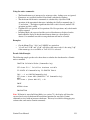
RS 232 Interface ........................................................................................... 80
6.1.1
Pinout and Wiring................................................................................. 80
6.1.2
Settings.................................................................................................. 82
6.1.3
Troubleshooting Serial Communications ............................................. 82
6.2
Hand Controller port ..................................................................................... 82
6.3
Serial Command Sets.................................................................................... 83
6.3.1
Meade LX200 Commands ................................................................. 83
6.3.2
Gemini Native Commands.................................................................... 84
6.4
Connecting a GPS Receiver.......................................................................... 84
6.5
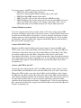
Using Planetarium Programs ........................................................................ 85
6.5.1
Telescope Driver................................................................................... 85
6.5.2
Communication Port Access................................................................. 85
6.5.3
Coordinate Epoch.................................................................................. 85
6.5.4
Coordinate Precision............................................................................. 86
6.6
Using Control Programs ............................................................................... 86
6.6.1
Gemini Control Center – GCC ............................................................. 86
Troubleshooting ...................................................................................................... 87
7.1
Common Error Cases.................................................................................... 87
7.1.1
Gemini Does Not Start.......................................................................... 87
7.1.2
Motor(s) Slew Uncontrollably on Startup............................................. 87
7.1.3
Mount Tracks in the Wrong Direction.................................................. 87
7.1.4
Stalls While Slewing or Tracking ......................................................... 87
7.1.5
UTC Date or Time Setting Wrong........................................................ 88
7.1.6
GoTo or Park Commands Are Rejected ............................................... 88
7.1.7
GoTo Position is Completely Wrong.................................................... 89
7.1.8
Poor Pointing Accuracy ........................................................................ 89
7.1.9
Strange or Garbled Characters in Deluxe Hand Controller Display..... 89
7.1.10
Mount Takes Too Long to Center Object ............................................. 89
7.1.11
Mount Continuously Beeps................................................................... 89
7.1.12
Autoguider Calibration Problems ......................................................... 90
7.1.13
Gemini Displays “Autoguider Error” ................................................... 90
7.1.14
Serial Communications Problems......................................................... 90
7.1.15
"CMOS reset" Message upon Startup or Incorrect Date/Time ............. 90
7.1.16
Gemini Displays “DEC/RA motor lags” .............................................. 91
7.2
Debug Mode.................................................................................................. 91
Appendices............................................................................................................... 92
8.1
Gemini Menus............................................................................................... 92
8.2
Catalogs......................................................................................................... 97
8.3
Alignment Star List....................................................................................... 98
Gemini Users Manual
iii
8.4
Serial Line Protocol .................................................................................... 100
8.5
Serial Communications............................................................................... 124
8.6
Autoguider Port........................................................................................... 125
8.6.1
Connecting Autoguiders with TTL Outputs to Older Gemini Systems
125
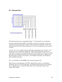
8.7
Encoder Port................................................................................................ 127
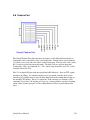
8.8
Feature Port................................................................................................. 129
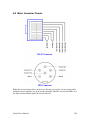
8.9
Motor Connector Pinouts............................................................................ 130
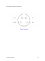
8.10 Power Connector Pinout ............................................................................. 131
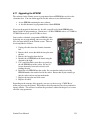
8.11 Upgrading the EPROM............................................................................... 132
Gemini Users Manual
iv
1 Introduction
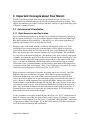
1.1 General Description
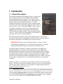
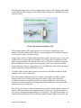
The Gemini Astronomical Positioning System is a professional
level computerized device for controlling small to medium
German equatorial telescope mounts. It was conceived and
designed by René Görlich (working in close collaboration with
Scott Losmandy, Norman Diehl and others)1 as a tool for
locating and tracking celestial objects, and for organizing both
visual observation and astronomical imaging sessions. Even at
its first release as Level 1 (November 2000), it could be used as
a completely standalone system, or be controlled from a PC
using planetarium software or the Gemini Control Program
(GCP) developed by Daniel Görlich. Each subsequent upgrade
(Levels 2, 3 and 4) added to its functionality, its convenience of
operation, and its remote control capabilities.
The Gemini has many features to help you be efficient and save time in your
astronomical observations. Although most should be intuitive, careful reading of
this manual will shorten your learning curve and ensure success.
IMPORTANT: Please read the “Quick Start Guide” (section 2.1 of this
manual) before attempting to use your Gemini for the first time. It contains
important information to help you start using your Gemini system.
One unique feature of Gemini is its ability to perform all of its functions by
navigating multiple menus using only five buttons and a single LED readout.
While the alternative would be a control panel with multiple specialized controls,
the simplicity of the Gemini system allows for almost unlimited upgrade without
rendering the basic hardware obsolete. Starting with the Level 4 software, it is
possible to add remote hand controller functionality using a PC or PDA. Since this
is done using a serial protocol, it is even possible to design a new custom hand
controller.
Gemini is available as a retrofit kit, or pre-installed on your telescope mount at the
factory. The most recent version of Gemini's software, Level 4, is provided with all
new telescope mounts. This level is also available as a simple plug-in upgrade to
anyone who already owns Level 1, 2 or 3.
1
René Görlich: Original concept, control electronics, and all software programming, except for the servo
subsystem. Scott Losmandy: Had developed a servo motor board at Aveox, Inc., developed all the mechanical parts,
named the combined/finished device "Gemini," and is the producer. Norman Diehl: Co-developed control electronics
for the stepper motors (including DSC capabilities), and assisted with development of Gemini's circuitry and board
layout. George Radda and David Palombo: Developed the servo control, final board layout, and software for the
servo processor's manufacture (at Aveox, Inc.). Wolfgang Steinicke: Revised NGC/IC catalogue. Peter Ward:
Southern hemisphere testing. Many ideas for features and improvements from all.
Gemini Users Manual
1
1.2 Features
1.2.1 Physical Features
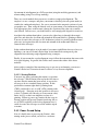
The Gemini Astronomical Positioning System is a professional level computer-to-servo
device for controlling a German Equatorial telescopic mount (GEM). It consists of four
components: (1) A computer board housed in a flat aluminum panel box to be attached by
screws to the pier of your GEM mount; (2) A right ascension servo motor connected
mechanically to the mount's RA shaft, and electrically to the Gemini computer via a
cable; (3) A declination servo motor (identical to the RA motor) connected mechanically
to the mount's Dec shaft, and electrically to the Gemini computer via a cable; and (4) a
Hand Controller with buttons, switches, and an 16 character LED display connected to
the Gemini computer via a serial cable. A fifth component, though essential, is not
provided as part of the Gemini package. It is a 12 to 18 volt D.C. power source that may
be either a storage battery or a well-regulated power supply.
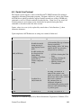
1.2.2 Operational Features
The following is a list and brief description of Gemini's operational features:
Setup Features
(a) Hand Controller Setup
The user chooses one of three movement control modes; they are (1) Visual Mode for
centering and slewing, (2) Photo Mode for centering and guiding, and (3) All Speeds
Mode for centering, slewing, and guiding.
(b) Mount Parameter Setup
The user selects the mount's tracking, slewing, centering, guiding and GoTo speeds, sets
a TVC value if any, trains and activates the Periodic Error Control (PEC) function,
selects the type of mount being used, sets safety limits for the mount's RA movement,
and sets the mount's home position for parking.
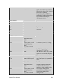
(c) Encoder Setup
If accessory RA and Dec axis encoders are installed, the user inputs their resolution, and
can test them or turn them on and off. Alternatively, end switches can be connected to
the encoder port and configured to physically limit the mounts motions.
(d) Alarm Timer Setup
The user can set a timer for an audible alarm to sound. The alarm can be turned on and
off. The buzzer can also be set to be silent.
(e) Date and Time Setup
The user inputs the current UTC date and time. Alternatively, the UTC date and time can
be automatically set by a GPS receiver in the Geographic Location Setup described
below.
Gemini Users Manual
2
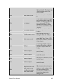
(f) Restore Default Function
The user can restore all setup items to their default Losmandy or Mountain Instruments
values.
(g) Brightness of Display Setup
The user can adjust the brightness of the Hand Controller's LED display.
(h) Geographic Location Setup
The user can either input the mount's longitude and latitude manually, or achieve the
same thing automatically, including setting the mount's UTC Date/Time and Time Zone
via a GPS receiver connected to Gemini's serial port. There are 4 sites available for
storing and reloading observing site data.
(i) Communication
The user can determine the equinox of any coordinates sent to Gemini. This selection
applies to coordinates transferred to and from planetarium and other telescope control
software as well as coordinates entered directly by the user. Either J2000.0 or the
Equinox of the Date can be selected. Also, the baud rate of the standard RS232 port, the
serial hand controller port and the GPS receiver can be set.
(j) Modeling
Once established, up to 10 telescope pointing models can be stored and reloaded. Also,
the last Additional Alignment operation can be undone.
Control Features
(a) Telescope Alignment
Gemini automatically initializes its celestial coordinate system when it is powered in the
standard startup position (counterweight shaft down and OTA pointing to the celestial
pole). This permits Gemini to GoTo (with reasonable accuracy) a first alignment star to
be synchronized. A list of Bright Stars that are currently above the horizon is provided;
selecting one of the stars triggers a GoTo operation. Additional star alignments can then
be performed in order to develop and refine a computerized pointing model for greater
GoTo accuracy. Under certain circumstances (e.g. changing eyepieces, rotating
diagonals, etc.), stars found and slewed to by the Gemini are no longer centered in the
eyepiece. To adjust for this occurrence, Gemini includes a synchronization feature that
allows an object to be re-centered without changing the pointing model. Finally, Gemini
includes a polar alignment assistance feature, and a Polar Axis Correction feature; the
latter requires that a pointing model first be established.
(b) Telescope Movement
Gemini allows tracking in 6 speeds: Sidereal, Lunar, Solar, Adaptive King Rate, Closed
Loop, Comet/User Defined, and Terrestrial (tracking turned off). In addition, the Hand
Controller permits the user to move the telescope in both RA and Dec in 3 speeds that are
established in the setup menu: Guiding, Centering, and Slewing. The user can also
perform GoTo movements of the telescope at a separate speed that is also established in
Gemini Users Manual
3
the setup menu. When a GoTo operation occurs, the telescope moves at GoTo Speed,
and then slows down to Centering Speed as it approaches its target. Telescope parking is
a separate command that disables tracking and moves the mount to a predetermined
Home position – by default, counterweight down with the telescope pointing to Celestial
North. Finally, all telescope movement stops and an alarm sounds when the mount slews
to either its Eastern or Western safety limit. A warning also sounds when the mount
approaches its Western limit while tracking.
(c) Databases
Databases of many well-known celestial objects are permanently stored in the Gemini.
These are arranged in eleven descriptive lists and/or astronomical catalogs. The RA and
Dec. coordinates in these databases are standardized to epoch J2000.0, and are precessed
to the equinox of the day; consequently, once the mount and Gemini are properly aligned,
the user can accurately slew to any of these objects. In addition to the permanent
databases, Gemini also contains a customizable (user-defined) database where the user
can conveniently input and store the names and coordinates of his or her most oftenobserved celestial objects. This list can be retained or erased at will. Finally, Gemini
allows the user to set and return the telescope to marked coordinates called Bookmarks.
(d) Displaying Date, Time, Pointing Coordinates, and Object
If the mount and Gemini are star-aligned, Gemini is able to provide the user with an
accurate RA/Dec and Az/El coordinate readout of any position to which the mount is
pointing, and is also able to identify (within a level of probability), the most likely
celestial object in the field of view, filtered by type of object and magnitude. It can also
show the current date and time in UTC, Civil Time, Julian Date, and Local Sidereal
Time.
(e) Object Search
Sometimes the user knows the approximate position of a celestial object, but the object is
not in the field of view. Gemini can search for the object in two ways: (1) by starting at a
known coordinate and scanning in an outward pattern limited to a 5 arc minute to 2
degree FOV, and (2) by moving in a "Z" shape, 5 arc minutes per axis, to help recognize
faint objects.
(f) PC Control
Gemini can be controlled by a remote computer via an RS232C serial cable. Such
control is most often accomplished with planetarium software using the LX200 protocol,
the ASCOM standard or with the Gemini Control Center program available online from
Daniel Görlich at http://www.DocGoerlich.com/GCC. The serial command set
description allows the development of custom software. In addition, Gemini's Feature and
Encoder Ports can be used to control user-designed hardware.
(g) QuickMenu
This menu duplicates functions found elsewhere in the menu tree, but is convenient to (1)
quickly change Gemini's Centering Speed incrementally from 2X to 128X, (2) quickly
change Hand Controller Mode to either Visual or Photo, (3) quickly park the mount in the
Gemini Users Manual
4
startup or pre-determined Home position, and (4) initiate a meridian flip if possible. A
focusing feature is also available on the QuickMenu, but is only usable when an auxiliary
adapter board is connected.
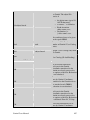
1.3 What’s New in Level 4?
1.3.1 Gemini Supports Custom Mounts
In addition to support for Losmandy and Mountain Instruments mounts, Gemini L4 now
supports custom mounts. The user can setup the main parameters of his mount: the gear
ratios and direction of spur gear and worm gear and the servo motor encoder resolution.
The step resolution can reach from 0.1 arcsec per step (servo motor encoder tick) up to
2.5 arcsec/step. Resolutions can be set independently for RA and Dec. axes.
With this new feature, Gemini can be retrofitted to many German Equatorial Mounts, for
example mounts with 359:1 Byers gears, Vixen or Astrophysics mounts. Existing servo
motor/encoder combinations can often be used, eliminating the need for mechanical
adapting the Gemini motor assembly, although custom cables will be necessary.
1.3.2 Supporting the Horizontal Coordinate System
The new Level 4 software supports the usage of Azimuth and Elevation coordinates.
These coordinates can be used for queries and GoTo operations over the serial line (see
Serial Command Set below) as well as by means of the hand controller.
The HC main menu item "RA/DEC Coord." is now called "Coordinates" and contains the
additional submenu items "Az/El Display" and "Enter Az/El".
1.3.3 Selectable Serial Port Transmission Rates
Gemini L4 allows you to set several transmission rate values for the serial (RS232) and
the serial hand controller ports, from 4800 up to 38400 bit/s, under the
Setup→Communication menu item. The default value is 9600 bit/s.
1.3.4 Selectable GPS transmission rate
The GPS speed can be set to 4800 or 9600 bit/s using Setup→Communication→GPS Rx
speed menu item. The default value after a reset is the standard NMEA 0183 speed of
4800 bit/s. By setting the GPS receiver transmission rate, Gemini's startup process is
accelerated, because the other rate doesn't have to be probed. Also, the query result
message display can by interrupted by pushing the menu button.
1.3.5 Reduced Main Menu selection available
After having set up Gemini and aligning the telescope or building a pointing model, some
of the menu items are rarely used. The new "Reduced Menu" mode only displays the
main menu items normally used while observing: Object Database, Show Information,
GoTo, RA/DEC Coordinates and Identify while scrolling downwards (with the DECbutton). Scrolling upwards with DEC+, Align Telescope is additionally included to allow
refinement of the pointing model. The other main menu items, Setup, Object Search,
Show Date/Time and GuideTo are suppressed. At any time it is possible to switch back to
Full Menu Mode using the Quickmenu feature.
Gemini Users Manual
5
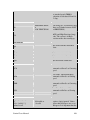
1.3.6 Redesigned Quick Menu selection
To accelerate the Quick Menu access and to offer more selections, the Quick Menu
feature was redesigned.
1.3.7 Parking the OTA
The telescope can be parked at any "Home Position" by either the hand controller or
serial control. The home position defaults to the CWD (Counterweight Down) position.
Additional commands have been added to the QuickMenu to provide additional parking
options and to stop tracking.
1.3.8 More Alignment Stars
The number of Alignment Stars has been extended to 49. Especially more southern
hemisphere objects are now included. The coordinates of these stars are stored with subarcsecond precision. Since some bright nearby stars have a significant proper motion
these motion values are also stored and included into the calculation to achieve highest
alignment accuracy.
1.3.9 Extended Serial Line Protocol
The Level 4 serial command set was extended not only to reflect the additions for new
and custom mounts, but also includes commands necessary for dome control and other
operations. :GA# and :GZ# commands are supported to query the azimuthal coordinates.
The hour angle the mount is pointing at can be obtained using the new :GH# command.
The side of the mount the OTA is can be asked for with :Gm while :GS# now delivers
the sidereal time. There are new precision guiding commands, observing sites can be
managed (stored, loaded, named), the firmware version information was extended and
more. Meridian flips can be initiated by the new :Mf# and :MM# commands.
1.3.10
Extended Identify interface
The interface to the Identify function within Gemini was extended to remember the
results of the latest Identify run. Now the user can decide to use
•
•
•
"New Selection" to do another Identify run,
"Previous objects" to observe one of the 10 objects found by the latest run,
"Continous Ident" to have the Identify routine running continously in the
background while the telescope is slewed manually or commanded over the serial
line, always displaying name and distance of the nearest object matching the
search criteria.
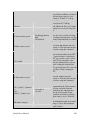
1.3.11
Extended Safety Limits Handling
The physical positions of the Safety Limits are automatically derived from the mount
settings. For Losmandy mounts, they default to 114 degrees when the telescope is on the
east side of the mount and to 123 degrees on the west side, with respect to the startup
(CWD) position. To avoid accidentally setting the safety limits, another submenu item
"Confirm to Set" was added as a submenu of "Setup→Mount Parameters→Set Safety
Limits".
Gemini Users Manual
6
Additionally, a second submenu item "Reset to Defaults" was introduced there to allow
you to reset only the Safety Limits to their default values (both east and west) without
having to reset all the other Setup values.
Another new submenu, “Set GoTo”, allows you to define a point past which Gemini will
always GoTo the object so that the telescope tube is on the east side of the mount.
Gemini will allow the mount to track past this point, but will not GoTo any object west of
this point without a meridian flip, if needed, to put the telescope tube on the east side of
the mount. The default value, displayed as 0 degrees, sets the GoTo limit to the western
safety limit minus 2.5 degrees, allowing for at least 10 minutes of tracking.
1.3.12
Selectable PC Synchronization Behavior
Gemini accepts two different kinds of Sync commands over the serial line. The LX200
protocol :CM# command shifts the internal coordinate system to reflect the latest position
correctly, "Synchronizing" it to an object. On the other hand, the additional ":Cm#
command uses the detected positional difference to enhance the internal pointing model.
The software running on a connected computer can choose between either.
Since there are still some software packages on the market not supporting the Additional
Align feature, Gemini's software now allows you to set the way :CM# and :Cm#
commands are interpreted. The Setup→Communication menu item now contains a "Sync
or Align" submenu. "Sync Only" selects Gemini's standard behavior as described above,
while "Sync→Add. Al." swaps the functionality of both commands, allowing
enhancement of the pointing model even with PC software not supporting this explicitly.
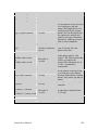
1.3.13
Precision Guiding Commands
The serial command protocol has been extended to allow precise movement commands to
be sent to Gemini. These commands include:
• Move at guide speed for a specific number of milliseconds
• Move at guide speed for a specific number of steps
• Move at guide speed for a specific number of arcseconds.
Gemini Users Manual
7
2 Getting Started
Now that you’ve unpacked your Gemini unit, you are no doubt eager to start using it.
Please take some time to read through this section of the manual before using your
Gemini for the first time. It will guide you through installation and first use of your
Gemini, and introduce you to some important concepts for using your German equatorial
mount.
2.1 Quick Start Guide
Although it is highly recommended that you read through this entire chapter before using
Gemini for the first time, this section is provided as a quick start guide to give you an
overview of the process, and to use as a reference after you have read the remainder of
the chapter.
•
•
•
•
•
•
•
•
Connect motor and power cables. Make sure they are oriented correctly and
inserted completely into the socket.
Position your mount with the polar axis pointing to the celestial pole.
Position RA and Dec. axes so that the counterweight shaft is pointing down, and
the Dec. axis is at 90° (OTA pointing at the celestial pole). This position will be
called “Startup Position” or “Counterweight Down” position, abbreviated
“CWD”.
Move power switch to the “on” position.
After seeing several system messages, select “Cold Start”. Note that Gemini may
automatically cold start if its internal memory does not contain valid data.
Enter date/time, geographic location, and mount type during the cold start
sequence. Alternatively, you can use the “Setup” menu to enter this data after the
cold start has completed. Note: this step assumes that you do not have a GPS
connected. Otherwise the date/time and location will be read from the GPS, and
Gemini will display “SRAM/RTC updated!”
Choose 3 to 5 alignment stars from the Alignment Star List (see Appendix 8.3)
which are on the same side of the meridian and are well separated in RA.
Align the mount on the first star using the following sequence:
o Select “Align Telescope→GoTo Bright Star.” Note: Do not confuse this
with the Bright Star Catalog. There is a separate menu item under “Align
Telescope” called “GoTo Bright Star.”
o Select your first alignment star from the submenu
o Mount will slew close to that star
o Use Hand Controller buttons to center the star in the eyepiece. Note:
Press and hold a direction button on the hand controller to move the
telescope. To move the telescope faster, momentarily press and release
the opposite button while continuing to depress the original button. Please
see section 2.3.4 below for a complete description of moving the mount
manually.
o Select “Align Telescope→Synchronize”
Gemini Users Manual
8
Display will confirm the object to which you are pointing
Press RA+ to complete the initial alignment
For each of your other alignment stars selected in step 7:
o Select “Align Telescope→GoTo Bright Star”
o Select the alignment star from the submenu
o Mount will slew to that star
o Use Hand Controller buttons to center the star in the eyepiece
o Select “Align Telescope→Additional Align” Note: Do NOT use the
“Additional Align” command until you have slewed to the next star using
steps a-d above. Doing so will result in the message “Sorry, rejected.”
o Display will confirm the object to which you are pointing
o Press RA+ to complete the alignment
o Gemini will display 2 numbers indicating the calculated offset in
arcseconds from the pole in Azimuth (A) and Elevation (E). (e.g. “A:+15
E:-10”)
Choose an alignment star on the opposite side of the meridian (see Appendix 8.3).
Perform the same operations as in step 9 to complete an “Additional Align” on
that star.
You should now be ready to observe.
o
o
•
•
•
•
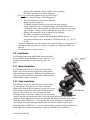
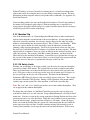
2.2 Installation
If you bought your mount with Gemini already installed,
you can skip the motor installation section. However, you
should review the other sections covering cables and
power.
2.2.1 Motor Installation
If you bought your Gemini as an add-on to an existing
mount, you will first need to replace the existing motors
with the Gemini servomotors. Follow the instructions that
came with your Gemini kit to remove the existing motors
and install the Gemini servomotors.
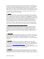
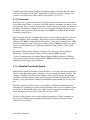
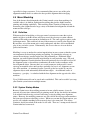
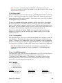
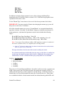
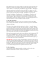
2.2.2 Cable Installation
You will have one of two different types of motor cables
for your Gemini. You may have two flat 8-connector
ribbon cables with an RJ-45 connector on each end, or you
may have two round cables with 6-pin DIN connectors at
each end. These cables are used to connect the drive
electronics to the servomotors. Both cables are electrically
identical, but one is longer than the other. Plug one end of the shorter cable into the
connector on the right ascension motor and the other end into the connector on the drive
electronics labeled “RA Servo.” Now take the other cable and plug one end into the
connector on the declination motor and the other end into the connector on the drive
electronics labeled “DEC Servo.” It is very important that you always plug the RA motor
into the RA Servo connector and the Dec. motor into the DEC Servo connector.
Gemini Users Manual
9
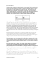
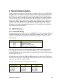
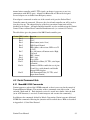
2.2.3 Encoders
Gemini can take advantage of optional encoders on your mount. Plug the encoder cable
into the 8-pin socket below the HC input. The layout is compatible with the Y-cable of
the usual DSCs, like the Losmandy DSC or the NGC Max. The encoder ratios and
directions can be set using the “Setup→Encoder” menu item. The default setting is
(minus) -4096 for both axes, as used for the G-11 mount. The sign indicates whether the
encoder is moved in the same or the opposite direction as the axis to which it is
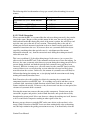
connected. Refer to the table below for other Losmandy mount encoder settings.
Mount
Encoder Tics
GM-8
-4096
G11
-4096
HGM200
+8192
Although Gemini does not require encoders to function, there are some advantages to
using them. Encoders allow the system to keep track of the telescope's position even
when you are moving the telescope manually with the clutches loosened. Unless you
have encoders, you should never loosen the clutches because to do so will cause the
system to lose information both about where it is pointing, and about how close the
mount is to the safety limits. The system must know where the eastern and western limits
are, and when it has to make a meridian flip. Using encoders, the system is informed
about manual movements and can take them into account, thereby avoiding exceeding the
limits.
The Gemini software is designed to give you the best of both worlds. As long as the
position signaled by the encoders is consistent with the motor position within two
encoder ticks, the far more accurate motor position is used. But if the encoders signal a
change, the system trusts them and corrects its internal address values.
When this happens, you see the characters R (for RA address correction) or D (for Dec.
address correction) displayed at the rightmost place of the system's display. This can be
an indication of manual movement, mechanical slippage, or a wrong encoder resolution
setup.
Even if the encoders are set "Online" (by selecting “Setup→Encoder→Use Encoder”)
you can use the system without the encoders being connected. Encoder values are
ignored until the first time a position change is signaled (the encoders are auto-detected).
On the other hand, you must not connect encoders while the system is running. If you
intend to use them only at certain times, you can enable or disable them using the
“Setup→Encoders” menu items.
Although Gemini supports encoders, the vast majority of Gemini users do not them.
Once you are familiar with slewing using the hand controller, the database, Identify and
GoTo functions there is little need to move the telescope manually. Even if you do move
it manually it can easily be synchronized again.
Gemini Users Manual
10
2.2.4 Power Requirements
The Gemini System requires 12–18 Volts DC, 3 Amps to operate. You will need to have
a battery or regulated DC power supply. Your choice of power supply is very important!
Many DC power units are not regulated, provide too little current, and too little or too
much voltage. This can cause problems with the Gemini. If you plan to run other
equipment from the power supply, make sure it has enough additional capacity. Choose
your power supply carefully to meet the requirements mentioned above, and avoid
potential problems such as long power cables. The Losmandy DC power supply
(available separately) meets all the above requirements.
2.3 Hand Controller Overview
The Gemini System comes with the Deluxe Hand Controller. All functions of the
Gemini System are accessible using just the four diamond shaped buttons, and the
MENU button. The built-in LED display provides information about all of the Gemini
System's features and menus. This simple arrangement gives you complete control with a
minimum of effort. Because the Gemini has such a large number of features and options,
navigating through the menus can be somewhat overwhelming at first, but after a little
practice, you'll find this arrangement quite intuitive and very easy to operate. All of the
settings in the Setup menu are stored in non-volatile memory, so you won't have to set
them each time. There are also shortcut keystrokes that will give you instant access to
some features.
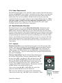
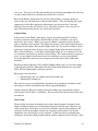
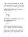
2.3.1 Controls
The Hand Controller has two main functions. It is used to move the telescope in RA
and Dec., and to access the Menu. Pressing the MENU button on the Hand Controller
toggles between Telescope Control Mode and Menu Mode. After completing the
startup sequence, the Gemini System goes into Menu Mode, offering the main menu
item “Align Telescope”. After 15 seconds without any user input it will fall back into
Telescope Control Mode.
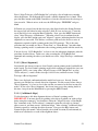
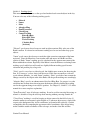
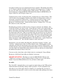
Telescope Control Mode: The four diamond shaped buttons move
the telescope in RA and Dec. The upper diamond button is DEC+,
the lower one is DEC–, the right one is RA+ and the left one is RA–.
At power-up, the RA and DEC buttons default to these functions.
The square RA REV and DEC REV buttons on the bottom can be
used to reverse (toggle between) the + and – functions on the
respective RA and DEC (diamond) buttons. The functions of the RA
and DEC buttons are not marked for this reason.
Unless reversed using RA REV or DEC REV, RA+ moves the
mount west in RA while RA- moves the mount east.
DEC+ moves the declination axis of the mount counterclockwise
(when viewed from the top), while DEC- moves it clockwise. When
Gemini Users Manual
11
moving in declination, the direction does NOT change as the mount crosses the celestial
pole.
Menu Mode: Press the MENU button and "MENU" is displayed. The DEC+/– buttons
scroll through the possible selections, the RA+ button selects items (like a computer's
'enter' key), and the RA– button usually goes back to the previous selection (like a
computer's 'back arrow'). Pressing the MENU button again returns Gemini to Telescope
Control Mode for guiding, centering, and slewing the telescope.
Note 1: There are some commands in the menu that will switch back to Telescope
Control Mode without pressing the MENU button.
Note 2: The RA REV and DEC REV buttons affect the Hand Controller in both
Telescope Control Mode and Menu Mode. For example, if you have pressed RA
REV, the left-hand RA button now selects items in the menu, and the right-hand RA
button is used as a back-arrow key.
Note 3: After about 15 seconds of inactivity at a top-level menu item, the Hand
Controller will automatically switch back to Telescope Control Mode.
Display: When in Menu Mode, the display shows the menu items and data for each item.
When you enter the Telescope Control Mode, the display will usually show a status
message (such as the current tracking rate) for a few seconds and then will go blank. For
example, after a GoTo operation, the display will show “FINISHED” for a few seconds,
and then go blank. However, selecting some menu items such as “Show Date/Time” and
“RA/DEC Display” will display the requested data (date/time or RA/Dec. coordinates),
then go into Telescope Control Mode, but will not blank the display.
2.3.2 Menu Structure/Navigation
The Gemini menu system is organized as a series of menu items, many of which have
sub-menus. A diagram of the full menu structure can be found in Appendix 8.1. You can
enter the Menu Mode at any time by pressing the MENU button on the Hand Controller.
Once you are in Menu Mode, you can scroll through the menu items using the DEC +/buttons. To select any displayed menu item, press the RA+ button. If the selected menu
item does not have any sub-menu items associated with it, this will immediately execute
the selected function. However, if the selected item does have sub-menu items, the Hand
Controller will display the first item in the sub-menu. Pressing the DEC +/- buttons will
now scroll through the items in the sub-menu. Pressing the RA- button will return you up
one sub-menu level.
For some menu items, you will need to enter numeric data. This is easily accomplished
using the direction buttons on the Hand Controller. When you come to such a menu item,
the far left digit (or sign, if any) of the number will be flashing to indicate that it can be
changed. To change the digit, use the DEC+ and DEC- buttons to scroll through the
digits 0-9. When the digit you want to enter is displayed, press RA+ to move to the next
digit to the right. RA- acts as a back arrow key to move back to the previous digit. When
you are finished entering the last digit, press the RA+ button again to enter the keyed-in
number.
Gemini Users Manual
12
2.3.3 QuickMenu
If you press and hold the MENU button for at least one second, a selection of useful
menu items such as Centering Speeds, Hand Controller Modes, and Telescope Park
commands scrolls through the display. The item that is displayed at the moment you
release the button is selected. Some QuickMenu items have submenus that will scroll
through the display. Pressing the MENU button again selects the current submenu item
being displayed. After a QuickMenu item is selected, Gemini returns to the Telescope
Control Mode.
2.3.4 Moving the Mount Manually
When you are in Telescope Control Mode, you can move the telescope with the buttons
on the Hand Controller. There are three basic movement speeds: Guiding Speed (0.2 to
0.8 of the tracking speed), Centering Speed (up to 255 times the tracking speed), and
Slewing Speed, which can be adjusted separately for manual slewing (with the Hand
Controller) and slews performed by a GoTo operation. Holding down a button causes the
telescope to move. Momentarily pushing down the opposite button while the telescope is
moving causes it to accelerate to the next higher movement speed.
The Hand Controller works in one of three modes: the Visual Mode, the Photo Mode and
the All Speeds Mode. You can move both axes simultaneously in all 3 modes. You select
the mode by means of the Setup→Hand Controller menu item. Like some other settings,
it is remembered permanently and will be in effect even after powering off and on again.
The Visual Mode
In visual mode, the Guiding Speed is not available. When you press a button, the
telescope moves at Centering Speed. Momentarily pushing the opposite button lets the
system accelerate to the manual slewing speed. If you are moving both axes, both will
speed up. Ramping up and down in speed occurs independently for both axes.
This mode is intended for visual observing and for looking up objects. The autoguider
port is not active in this mode.
The Photo Mode
In Photo Mode, Guiding Speed is the principal speed, so pressing a Hand Controller
directional button moves the telescope at the selected Guiding Speed; Slewing Speed is
not available. Acceleration to Centering Speed is available in four stages (to allow easy
centering of an object in the field of view or on a CCD chip) by pressing the opposite
button while Gemini is guiding:
Pressing the opposite button once changes to 1/8 of Centering Speed to allow fine
centering of the target. Then, after about 2 seconds, the speed will increase to ¼
Gemini Users Manual
13
Centering Speed, after another 2 seconds to ½ Centering Speed, and finally to full
Centering Speed.
Pressing the opposite button twice changes to full Centering Speed immediately.
If you want to guide a photograph manually, you may plug a Standard (not Deluxe) Hand
Controller into Gemini’s autoguider port. This way you are sure that you cannot
accidentally move the scope at centering speed while guiding. The LED on the standard
Hand Controller will not be illuminated when plugged into the autoguider port.
The All Speeds Mode
In this mode, all speeds are available, from Guiding Speed to Slewing Speed, by using
the opposite-button trick. You can use this mode, for example, while drift aligning, when
you need very fine centering of a star at the crosshairs and a fast move from the meridian
to the eastern or western horizon. However, for normal observing, you'll probably select
either the Visual or Photo Mode.
2.4 Basics of Operation
This section will walk you through getting your Gemini system set up and running for the
first time. The steps that we’ll follow are:
•
•
•
•
•
•
•
Setting up for observing
Rough Polar alignment
Putting the telescope in Startup Position (positioning scope with the
counterweight down and the OTA pointing north if in the northern hemisphere, or
south if in the southern hemisphere).
Powering on
Setting parameters (mount type, time/date/location, etc.)
Aligning mount using alignment stars
Using the mount
2.4.1 Setting Up for Observing
Once you’ve completed the Gemini installation and have connected all the cables, you
are ready to set up for observing. IMPORTANT: As with any telescope mount, make
sure your telescope is properly balanced in both RA and Dec. before continuing. Do this
with all eyepieces and accessories that you intend to use attached. Refer to the
instructions for your mount to help you with this.
2.4.1.1 Rough Polar Alignment
In order to function correctly, your mount must be approximately polar aligned. This
means lining up the mount’s polar axis with the Earth’s rotational axis. You do this by
pointing the mount’s polar axis toward the celestial pole (north celestial pole in the
northern hemisphere, and south celestial pole in the southern hemisphere). For visual
use, this alignment need only be within a few degrees since Gemini can compensate for a
Gemini Users Manual
14
fair amount of misalignment in a GoTo operation (using the modeling parameters) and
when tracking (using Closed Loop tracking).
There are several methods that you can use to achieve rough polar alignment. The
simplest is to use a compass and place your mount so that the polar axis points north (or
south in the southern hemisphere). Be sure to account for the magnetic variance of your
geographic area. Then, using the latitude scale on your mount (or an inclinometer placed
at an appropriate place on the mount), change the elevation of the polar axis to match
your latitude. In most cases, you should now be well enough polar aligned for visual use.
At night in the northern hemisphere, you can also sight along (or through) the mount’s
polar axis and adjust the elevation and azimuth of the mount until it is pointing at Polaris.
You can also move the telescope to 90° declination (so that it is parallel with the mount’s
polar axis) and again adjust the elevation and azimuth of the mount until Polaris is
centered in the telescope.
In the southern hemisphere or in the north if you cannot sight Polaris because of trees or
buildings, you can use Gemini's Polar Align Assist function for an improved polar
alignment after achieving rough alignment using a compass.
Finally, if your mount has a polar alignment scope, follow the instructions that came with
it for polar aligning. In general, this will be more accurate that either of the above
methods.
After you have completed the remaining steps to get you up and running, you can use
Gemini’s Polar Axis Correction feature to achieve a very accurate alignment.
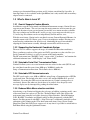
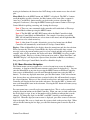
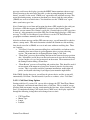
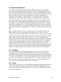
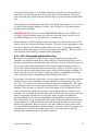
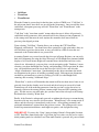
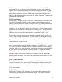
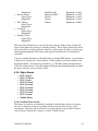
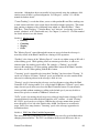
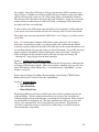
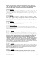
2.4.1.2 Startup Position
Your next step after positioning the mount is to position
the telescope. When Gemini starts up for the first time or
any time after the mount has been moved, it expects the
telescope to be in a standard Startup position. In this
position the counterweight shaft is pointing down
(CWD), and the Dec. axis is at 90° (OTA pointing at the
celestial pole). Powering on in this position is necessary
so that (1) Gemini will correctly set its movement safety
limits, and (2) so that it can initialize to where it is
pointing. Failure to power up Gemini with the scope in
Startup position will prevent Gemini from being able to
use its GoTo capability to find a first alignment star; it
could also cause the telescope to collide with the tripod
or mount.
2.4.2 Power On and Setup
Now it is finally time to power up the Gemini. After
turning on the power switch, you will see a welcome
Gemini Users Manual
15
message scroll across the display (pressing the MENU button terminates the message).
When powering up the unit for the first time, or after inserting/changing the internal
battery, you may see the words "CMOS reset" appended to the welcome message. This
means that during startup, an incorrect checksum was detected and the static memory
(SRAM) was reset to its initial values. You should not see this "CMOS reset" again,
unless your battery goes low.
Next, Gemini tries to read time and location data from a GPS attached to the serial port.
If you have a GPS that supports the NMEA0183 protocol or the Garmin Textout
Protocol, you can connect it to Gemini’s serial port. Gemini looks for a GPS every time
it starts up. After attempting to read the GPS data, Gemini briefly displays a GPS status
message. If a GPS is not connected, you will have to set the UTC Date/Time and
geographic coordinates manually at the first startup.
After the welcome message and the GPS status message, you will normally be asked to
choose a startup mode. This mode determines whether the Gemini uses the modeling
data already stored in its SRAM, or resets it and starts with new modeling data. There
are 3 options:
• “Cold Start” clears the current modeling data, and should be used whenever the
mount has been moved from its polar alignment after a previous observing
session. The mount must be in Startup Position during a Cold Start.
• “Warm Start” preserves the modeling data but not the current telescope position
data. It should be used if the mount has not been moved since the last observing
session, but the telescope has been moved on the mount. The mount must be in
the Startup Position during a Warm Start.
• “Warm Restart” preserves all modeling and position data. This should be used if
no movement of the mount or telescope has occurred since the last observing
session. This is especially useful for permanent installations, multi-night star
parties, and daytime observing if you aligned your mount the night before.
If the CMOS data has been reset, you will not be given a choice, and the system will
automatically Cold Start. For this tutorial, if you do see a choice, select “Cold Start.”
2.4.2.1 Cold Start Setup Options
Starting with Level 3 version 1.01, you are able to change the UTC Date/Time, Mount
type, Longitude, and Latitude immediately after a Cold Start. This is useful if you are
traveling with your mount, or using your mount for the first time. After selecting “Cold
Start” (or automatically being Cold started after a CMOS reset), the display sequences
through the following settings that can be changed one at a time:
•
•
•
•
UTC Date/Time
Mount Type
Longit.
Latitude
Gemini Users Manual
16
Each item will be displayed for a few seconds before going to the next one. If you want
to change the currently displayed item, press one of the four direction buttons on the
Hand Controller. To skip to the next item without waiting, press the MENU button. If
you miss setting an item at this time, you can always use the “Setup” menu to make the
change after startup is complete (see chapter 5 for details on using the “Setup” menu).
2.4.2.1.1 Setting the UTC Date and Time
The current UTC date and time must be entered into Gemini so that it can make correct
calculations for pointing the telescope. If you choose to set the UTC date and time
during startup, first note the display, which will show the current value. The format for
the date and time is “yymm.dd hh:mm:ss” and must be in Coordinated Universal Time
(UTC) – not your local time. Enter each digit of the date and time using the direction
buttons on the Hand Controller as described in section 2.2.2 above. The currently
selected digit will blink. After selecting the seconds digit, press RA+. Gemini will then
return to the startup process and allow you to change the next item.
Note: Remember that the UTC date at certain times of the day may be one day ahead
of or behind your local date.
2.4.2.1.2 Setting your Mount Type/Parameters
The Gemini system supports several different mounts, and needs to know which one you
are using. Gemini will display the currently selected Mount Type. If you choose to
change this item, use the DEC buttons to scroll through the mount types available. When
your mount is displayed, press the RA+ button to select it. Gemini will then return to the
startup process and allow you to change the next item.
2.4.2.1.3 Setting Your Location
In order to accurately position your mount, Gemini needs to know your position on the
Earth in addition to the current date and time. If you had a GPS connected during poweron, Gemini read this data and you can skip the next two steps. The GPS receiver can also
be read later using the menu item “Setup→Geogr. Location→Query GPS Rec.”
To set your geographic location manually during startup, press any direction button on
the Hand Controller when it displays either the Longitude or Latitude you wish to
change.
At the Longitude display, use the Hand Controller buttons to enter your Longitude as
previously noted. The longitude is counted from Greenwich, England; eastern longitudes
are designated by 'E', and western longitudes (including the American continent) by 'W'.
After you have entered the last digit, press the RA+ button again to set the longitude.
The display next shows “Latitude.” Press any direction button to initiate setting your
Latitude. Enter your Latitude using the RA and DEC buttons to change digits as you did
with Longitude. Northern latitudes are denoted by the “+” sign, while the “-” sign is used
for southern latitudes. After you have entered the last digit, press RA+ again to complete
the startup procedure.
Gemini Users Manual
17
2.4.2.2 Completing Startup
After the system has completed its startup tasks, it will display the UTC Date/Time,
Mount Type, and geographic location. It will then go into Menu Mode and display the
“Align Telescope” menu item.
Since the date and time you enter on the Gemini will be UTC, you need to set your time
zone for correct conversion to your local time. If the display has gone blank, you will
first need to get into Menu Mode by pressing the MENU button. Use the DEC buttons to
scroll through the menu choices until you get to "Setup" and then press the RA+ button.
You are now in the Setup submenu. Use the DEC buttons to scroll through the menu
choices until you come to “Geogr. Location” and press the RA+ button to select it.
Such navigation sequences will be abbreviated in this manual by using the names of the
submenu items separated by a right arrow “→” symbol. Thus, the menu item you just
chose would be depicted “Setup→Geogr. Location.” Finally, use the DEC buttons to
scroll through the menu choices until you come to “Timezone” and press the RA+ button
to select it.
The display will show the current time zone setting as some number of hours ahead of or
behind the time in Greenwich England. For example, the United States west coast is
UTC-8 hours or 8 hours behind Greenwich when daylight savings time is not in effect.
Press the DEC+ or DEC- buttons to scroll through the time zones. When your time zone
is displayed, press the RA+ button to select it.
Having set your location and time zone correctly, you can store them. Up to four different
locations can be stored and reloaded. These locations default to Hollywood CA, Colfax
CA, Berlin Germany and Sydney, NSW Australia, but can be overwritten by your own
settings. Use the “Setup→Geogr. Location→Store Site” command to store the site name,
coordinates and time zone. You can find more information about this command in
chapter 5.
2.4.2.3 Preferences
Finally, there are some preferences that you can set to tailor Gemini to your liking and to
your particular mount. Most of these are optional and can be changed any time. Such
items include:
• Hand Controller Mode (Visual, Photo, All Speeds)
• Moving Speeds (Slew, GoTo, Center, Guide). Changing the Slew and GoTo
speeds may be needed if a motor keeps stalling during a slew. Often slowing
these speeds down helps.
• Brightness of the HC display
Refer to chapter 5 for details about setting these and other options.
IMPORTANT: Changing your geographic location between northern and southern
hemispheres will reverse the tracking direction (and because of this, also the Safety
Limits). Gemini makes even more internal adjustments when you change the Mount
Gemini Users Manual
18
Type. If you alter either the Mount Type or hemisphere, restart the Gemini after
completing the Setup operation. Simply turn Gemini off and then on again to do this.
IMPORTANT: The default safety limits prevent the mount from hitting itself as it
moves. However, these safety limits may not be sufficient to prevent your OTA from
hitting either parts of the mount or the tripod. You should always check the safety limits
and reset them as appropriate for your specific equipment. Please see section 5.3.10.2.6
for information about setting the safety limits.
2.4.3 Refining the Mount's Alignment Model
Let’s review where you are at this point: You have assembled the mount and telescope,
and have carefully balanced them in both RA and Dec. You have leveled and roughly
polar aligned the mount by pointing the mount’s polar axis at the celestial pole. You
have positioned the mount in the Startup Position with the counterweight down and the
telescope pointing north (or south if in the southern hemisphere), and powered Gemini
on. Finally, you used Gemini’s menus to set the various parameters to make it work.
You are now ready to align Gemini’s internal modeling parameters.
In order to improve the accuracy pointing to objects in the sky, the Gemini software can
learn how the mount is oriented with respect to the celestial pole, what angle the
telescope is pointing to in both RA and Dec., the degree of non-orthogonality between the
telescope and the mount, etc. All of these parameters form Gemini’s “model” of the
mount and telescope. These parameters as well as others are built up automatically
through a series of alignment operations. Each alignment consists of pointing to a star
and telling Gemini when that star is centered. Accurate modeling allows accurate GoTo
operations, and the more alignments you perform (up to a point), the better the modeling
parameters can be determined. You can read more about the various modeling
parameters that Gemini uses in chapter 3.
As mentioned earlier, there are several modes in which Gemini can start up. For the
purposes of this section, we will assume that the mount was “Cold Started.” Subsequent
sections of the manual will explain the modeling and alignment process in greater detail
for each of the 3 startup modes.
2.4.3.1 Choosing Alignment Stars
Unless you are perfectly polar aligned and have no mechanical play or misalignment in
your mount and your telescope, you will need at least 3 star alignments in order to build
an accurate model. These must all be on the same side of the meridian – either east or
west. The first 3 alignment stars should be selected from Gemini's "Bright Stars" catalog
(database) and must differ in hour angle (distance in RA from the meridian) by at least
one or two hours. This means you either need to choose stars that differ in RA by at least
a couple hours, or wait a couple hours between alignments so that your next alignment
star will differ in hour angle from where your first alignment star was. For example,
doing an alignment on Capella and then on Rigel or Bellatrix is not a good idea; the same
is true for alignments on Procyon, followed by Castor or Pollux – there are only tiny
differences in RA between them.
Gemini Users Manual
19
Make sure that you are certain of the identification of all stars that you use for alignment.
If you misidentify a star that is far from the correct star, Gemini will reject the
“Additional Alignment.” However, if you align on the wrong star that is close to the
correct star, Gemini will accept the erroneous “Additional Alignment,” and errors will be
introduced into the pointing model causing inaccurate GoTo operation. You can use the
Setup→Mount Parameters→Pointing Model→Undo Last Align command to undo the
most recent alignment done.
2.4.3.2 Slewing to and Aligning on your First Star
After you have chosen 3 alignment stars, you are ready to start the alignment process.
When you cold started, Gemini assumed that the mount was perfectly polar aligned,
level, in the counterweight down position, and that the telescope was pointing north (or
south in the southern hemisphere). It then built an initial model based on these
assumptions.
Select and GoTo the first of the chosen alignment stars. The easiest way to do this is to
select the “Align Telescope→GoTo Bright Star” from the menu. You can then use the
DEC buttons to scroll through the list of Bright Stars that are currently above the horizon.
When you see the name of the star you want to use, press the RA+ button, and Gemini
will slew close to that star. Depending on how well you polar aligned your mount and
assuming that your location, date, and time are all accurate, the target star may even be in
the field of view of a low power eyepiece. The Hand Controller will now be in Telescope
Control Mode, and you should use its buttons (with the aid of a finder scope if necessary)
to locate and center the star in your eyepiece. Once the star is centered, press the “Menu”
button to enter Menu Mode, and select “Align Telescope→Synchronize.” It will confirm
the object you are pointing to. Finally, press RA+ to complete the first step of alignment.
To summarize:
• Choose 3 alignment stars that differ in RA by at least one or two hours
• Select “Align Telescope→GoTo Bright Star”
• Select your first alignment star from the submenu
• Mount will slew close to that star
• Use Hand Controller buttons to center the star in the eyepiece
• Select “Align Telescope→Synchronize”
• Display will confirm the object to which you are pointing
• Press RA+ to complete the alignment
2.4.3.3 Additional Alignments
If you are satisfied with the rough accuracy of a one star alignment, you may skip this
section. Otherwise, you should now repeat a similar process with at least 2 more stars on
the same side of the meridian. Select “Align Telescope→GoTo Bright Star” from the
menu and select your next alignment star from the list of Bright Stars. Press RA+ to
GoTo that star, and again use the Hand Controller buttons to center the star in your
eyepiece. Now select “Align Telescope→Additional Align.” As before, Gemini will
Gemini Users Manual
20
confirm the object to which you are pointing by displaying its name. Press RA+ to
complete this alignment. Repeat the process for the third alignment star on the same side
of the meridian. This will establish a basic pointing model. You may continue to refine
the model on this side of the meridian by repeating the process with several more stars if
desired.
IMPORTANT: When using the “Additional Align” command, you must already be
pointing to the star on which you want to align. The easiest way to do this is to use
the “Align Telescope→GoTo Bright Star” command as described above. The
“Additional Align” command does not move the telescope. Failure to do this will
result in a “Sorry, rejected” message from Gemini.
Next, pick one more alignment star on the side opposite the meridian from the first 3, and
repeat the Additional Align process just described. The reason for doing this is that after
a meridian flip, you'll experience an offset in RA caused by play in the RA gear (Now the
opposite side of the worm and teeth are in contact). Additionally, some parts of the
system (such as the main mirror of an SCT) will have flopped to the other side. Adding
one more alignment after a meridian flip allows Gemini to know how big the play in the
RA gear and the flop are, and take them into account. For best results, choose a star in
the middle of the hemisphere, ensuring that the RA gear is in good contact. Refocusing
also helps to move the mirror into a stable position after the meridian flip.
To summarize:
• For each of your other 2 alignment stars:
o Select “Align Telescope→GoTo Bright Star”
o Select an alignment star from the "Bright Stars" catalog
o Mount will slew to that star
o Use Hand Controller buttons to center the star in the eyepiece
o Select “Align Telescope→Additional Align”
o Display will confirm the object to which you are pointing
o Press RA+ to complete the alignment
o Gemini will display the calculated offset from the pole in arcseconds in
azimuth (A) and elevation (E). For example, it might display “A:+15 E:10” to indicate that your mount is 15 arcseconds from the pole in azimuth
and 10 arcseconds from the pole in elevation.
• Choose a star on the opposite side of the meridian
• Perform the above steps for an Additional Align on that star
You should now be ready for normal operation with your Gemini. You can perform
more Additional Aligns any time during your observing session to further refine the
model. Be sure to read chapter 3 for more information about starting up and aligning
Gemini in its different startup modes, and for more details about Gemini’s internal
modeling capabilities.
Gemini Users Manual
21
2.4.4 Normal Operation
By now, you are no doubt eager to put Gemini through its paces. You can control your
mount using Gemini either from the Hand Controller or via a computer connected
through Gemini’s serial port. Chapter 5 describes these operations in great detail. The
present chapter concludes with a quick guide on how to use the Hand Controller to select
and GoTo objects in Gemini’s database.
2.4.4.1 Entering an Object of Interest
There are 2 ways to tell Gemini where you want it to go. The most common is to simply
select one of the thousands of objects from Gemini’s catalogs. However, if you want to
GoTo an object that is not in a catalog such as a comet, you can enter its RA and Dec.
coordinates manually using the commands in the “Coordinates” menu item.
Catalogs
Gemini has 11 permanently stored catalogs (databases) containing over 40,000 entries.
To select an object from a catalog, simply select the “Object Database” menu item. You
can then scroll through the catalogs using the DEC buttons; selecting one of the catalogs
then allows you to choose an object from that catalog.
Some catalogs such as the "Messier" and "NGC" catalogs require numeric entries to
choose an object. Other catalogs such as "Bright Stars" or "Solar System" allow you to
scroll through objects and select the object you want. In the case of the "Bright Star"
catalog, it is conveniently organized and subdivided according to the first letter of the
stars’ names. In all cases, once the object you want is displayed, press the RA+ button to
select it. A message is displayed, containing the object's distance to the meridian
(negative in the east) in minutes of time and the elevation in degrees.
Another way to acquire a catalog or object list is to compose it yourself. Using the
optional Gemini Control Center software, you can use your PC to prepare and download
your own catalog that can contain up to 4000 objects. This has the advantage of
including in your list only objects that will be used for a particular night's observation.
Coordinates
Another method of selecting an object is to enter its RA and Dec. coordinates directly.
Select “Coordinates→Enter RA/DEC” from the menu. You will then be shown the
mount’s current RA/Dec. location and be prompted to change each digit to the desired
coordinates. As with all numeric entries in Gemini, use the DEC+ and DEC- buttons to
change the flashing digit, the RA+ button to advance to the next digit, and the RA- button
to go back to the previous digit. After you have entered the last digit, press the RA+
button again to finish entering the coordinates.
By default, Gemini assumes that any coordinates you enter are for the epoch of the
current date. However, you can change Gemini’s default epoch to J2000.0 using the
Gemini Users Manual
22
“Setup→Communication→Coordinate Epoch→Epoch J2000.0” menu item. You can
find more details on this in chapter 5.
Alternatively, you can enter coordinates of the azimuthal coordinate system using the
Coordinates->Enter Az/El submenu.
2.4.4.2 GoTo Operation
After an object has been selected (either from the internal catalogs or by entering its
coordinates) a new menu item appears: “GoTo <object>” (where <object> is the
currently selected object). Simply select this menu item to cause Gemini to slew to that
object. As the telescope approaches the object, it will ramp down from slew speed and
finish pointing at centering speed. When the GoTo is complete, the display will show
“FINISHED.” If you have correctly built a good pointing model, the object should be
within a few arc minutes of the center of the field of view. You can then center it using
the Hand Controller, and either Synchronize, or perform an Additional Align if you want
to continue to refine the pointing model.
2.4.4.3 Tracking
By default, Gemini will track at the sidereal rate. This should be sufficient for visually
observing nearly any object if you are roughly polar aligned, but the tracking can be
changed to other rates if desired. It is important to note that continuous tracking will
occur while in either the Menu Mode or the Telescope Control Mode.
2.5 Next Steps
The steps outlined above are sufficient to get you started and provide you with many
hours of observing pleasure. However, we have only scratched the surface of the
Gemini’s many capabilities. Please take some time to read through the rest of the manual
for information regarding such topics as:
• Using Gemini to achieve better polar alignment
• Imaging (tracking rates, Periodic Error Control, using an autoguider, etc.)
• Startup modes
• Mount modeling
2.5.1 Gemini Users’ Group
You can exchange information and ideas with other Gemini users on the Gemini Users’
Group forum on Yahoo. You can get more information or join the group at
http://groups.yahoo.com/group/Gemini_Users.
Gemini Users Manual
23
3 Important Concepts about Your Mount
In order to get the most from your mount and the Gemini system, you’ll need to
understand a few important concepts about both astronomy and telescope mounts. This
chapter will introduce you to these concepts and show you how to apply them using some
of Gemini’s advanced features.
3.1 Astronomical Coordinates
3.1.1 Right Ascension and Declination
Just as any location on Earth can be described by its latitude and longitude, positions in
the sky can be described by a set of coordinates known as Right Ascension (abbreviated
RA) and Declination (abbreviated Dec.). RA and Dec. are the celestial equivalents of
longitude and latitude, and are actually closely related.
Imagine a globe of the Earth with lines of latitude and longitude drawn on it. Now,
extend those lines out from the globe to the imaginary celestial sphere on which are
placed all the objects in the sky. Directly above the poles of the Earth are the celestial
poles, and directly above the terrestrial equator is the celestial equator. The star Polaris
lies very close to the north celestial pole. Declination is easy since it exactly corresponds
to latitude, measuring the angle between the celestial equator and the celestial poles. Just
as lines of latitude run parallel to the equator and go from 0° at the equator to 90° at the
poles, so do lines of declination. Declination values are measured in degrees, minutes
and seconds of arc (or decimal minutes) and are positive when north of the equator and
are negative when south of the equator. Thus, a star at 46 degrees 12 minutes 42 seconds
south of the celestial equator is said to have a Dec. of -46° 12' 42".
Right Ascension is analogous to longitude, measuring angles east and west. And, like
longitude, RA needs an arbitrary zero-point. While the zero-point of longitude is
Greenwich, England, the zero-point of RA is that location in the sky where the Sun
crosses the celestial equator on its way north in the spring (also called the first point of
Aries). However, unlike longitude, RA is measured in hours, minutes and seconds (or
decimal minutes) from 0h 0m 0s through 23h 59m 59s. RA values increase as you move
east of the first point of Aries. Note that because the Earth is rotating to the east on its
poles, lines of constant declination remain in constant positions on the sky, but lines of
constant RA move from east to west in the sky during the night. We’ll look at this in
more detail in the next section of this chapter.
So, the coordinates of an object might look like 16h 42.9m +38° 55' 12" which means 16
hours 42.9 minutes east of the first point of Aries and 38 degrees 55 minutes 12 seconds
north of the celestial equator. You can use the “Coordinates→Enter RA/DEC” menu item
to input the coordinates into Gemini. If you then tell Gemini to GoTo those coordinates,
you’ll find yourself looking at M13 in Hercules.
Gemini Users Manual
24
Gemini displays RA in hours, minutes, and decimal minutes so that the RA value above
would be represented as 16h 42m9. Declination is displayed as degrees, minutes, and
seconds, so the above Dec. value would be represented as +38° 55' 12".
3.1.2 Precession
While most stars, galaxies and other deep sky objects do not move relative to each other
in any kind of time frame we can notice, their RA and Dec. coordinates do change slowly
over the years. This is because the coordinate system is based on the poles and equator of
the Earth. In addition to rotating on its axis once a day and orbiting the Sun once a year,
the Earth’s axis is precessing like a top once every 26,000 years taking the RA and Dec.
coordinate system with it.
This is why RA and Dec. coordinates always have a date associated with them, called the
Epoch or Equinox of the coordinates. Most sources now use Epoch 2000 coordinates
(abbreviated J2000.0), meaning that the RA and Dec. values were correct on Jan 1, 2000.
In order to accurately point a telescope at an object whose J2000.0 coordinates are given,
a precession calculation must be applied to determine the RA and Dec. values for the
current date.
By default, Gemini assumes that any coordinates you enter are for the epoch of the
current date. You can change Gemini’s default epoch to J2000.0 using the
“Setup→Communication→Coordinate Epoch→Epoch J2000.0” menu item, allowing
you to enter (or transfer from a connected PC) J2000.0 coordinates and letting Gemini
perform the needed precession calculation.
3.1.3 Azimuthal Coordinate System
Although the equatorial coordinate system (RA/Dec.) is best suited for most astronomical
objects, some applications require pointing to a given azimuth and altitude (Alt/Az). One
example is pointing to satellites in geostationary orbits. Gemini supports the azimuthal
coordinate system by allowing you to display the current altitude and azimuth as well as
allowing you to enter Alt/Az coordinates from both the hand controller or over the serial
line.
While the altitude of an object can be easily defined as the distance from the horizon,
azimuth needs an arbitrary zero-point and an orientation. There are two common systems:
one starting in the north, the other in the south. Gemini's zero point in azimuth is in the
north, increasing to the east (90°), south (180°) and west (270°).
In order to fit the display, the precision of Alt/Az coordinates is limited to minutes in
Visual mode. In Photo mode, azimuth and altitude are alternately displayed with an
accuracy of (arc)seconds.
Gemini Users Manual
25
3.2 How the Sky Moves
If you have spent any length of time outdoors looking at the stars, you’ve probably
noticed that everything in the sky shifts position over time during the night. Of course
this is due to the fact that the Earth is rotating on its polar axis. Recall that the celestial
poles in the sky lie directly above the Earth’s poles, so just as the Earth rotates around its
poles, the entire sky appears to rotate around the celestial poles, completing one
revolution in about 24 hours. Objects that lie close to the poles make small circles
around the pole, while objects further from the pole make larger circles, taking them
below the horizon for periods of time during their revolution. So, although an object’s
RA and Dec. don’t change significantly during the course of a night, a fixed telescope
aimed directly at a point on the meridian (the imaginary line passing directly overhead
from north to south) would see stars drift through it from east to west as increasing RA
values cross the meridian. It is important to understand that a fixed telescope points to a
constant Dec. value, but a changing RA value. This also explains why RA is measured in
hours.
There is another coordinate system – one that does not move with the rotation of the
Earth. Because it does not move relative to the Earth, it can be used to describe a
telescope’s position relative to the Earth. It uses the same Dec. value as does the rotating
system to measure angles north and south of the poles. But instead of RA, the so-called
"Hour Angle" is used to measure angles east and west. It too is measured in hours,
minutes and seconds (or sometimes just minutes), but uses the meridian as its zero point.
An object in the east has a negative hour angle. This value is interpreted as the number
of hours it will take for the object to arrive at the meridian. If it is due east, its Hour
Angle (abbreviated HA) will be -6h, meaning it will need 6 hours to arrive at the
meridian. Objects in the west have a positive hour angle, indicating the number of hours
the object is past the meridian. Gemini displays the hour angle of an object (in minutes,
together with the current elevation) at the time you select it from one of the databases.
3.3 Tracking
One of the jobs of a telescope mount and control system is to move the telescope to
compensate for this constant change in RA of the sky. In order to stay pointing at a
constant RA value, the mount must move at the same rate that objects in the sky appear to
move. This is called tracking. If your mount is polar aligned, then its polar (or RA) axis
is parallel with the Earth’s axis, and tracking should involve simply driving the mount in
RA at the same rate the Earth is turning. While this is a very close approximation for
stars, there are a few complications that need to be addressed.
3.3.1 Rates
Gemini can drive the telescope at several different tracking rates depending on the object
you are observing and how close your mount is to being polar aligned. The currently
active tracking mode is displayed briefly whenever you press the MENU button to enter
Telescope Control Mode.
Gemini Users Manual
26
3.3.1.1 Predefined Rates
Two predefined tracking rates drive the RA axis at a constant speed to compensate for the
Earth’s rotation.
Sidereal
Sidereal rate is simply the rate that compensates for the Earth’s motion relative to the
celestial sphere. It keeps the mount pointed at a constant RA and Dec. coordinate in the
sky and will probably be the rate that you use the vast majority of the time. With sidereal
tracking selected, the telescope makes one revolution per sidereal day (86164.0905
seconds). Note: The sidereal rate assumes that your mount is accurately polar aligned.
None/Terrestrial
This rate turns tracking off completely and allows you to observe stationary objects such
as points on land, or geosynchronous satellites. It is also useful for keeping the telescope
from exceeding its safety limits when the Gemini must be left on for extended periods of
time between observations.
3.3.1.2 Computed Tracking Rates
In addition to the Earth’s rotation, the computed tracking rates take many additional
factors into account such as the Earth’s orbit around the Sun, the Moon’s orbit around the
Earth, and an object’s position relative to the horizon.
Lunar and Solar
Neither the lunar nor solar tracking rates is constant. Since the orbits of Earth and Moon
are slightly elliptical, the apparent speed of Moon and Sun will change. When you select
the lunar or solar tracking rates, the tracking speed will be calculated based on the actual
position and the position one hour later.
Because the Moon orbits the Earth, its RA and Dec. change during the course of the
night. The lunar tracking rate compensates for the RA component of that change; there is
no compensation for the changes in Dec. While sidereal rate can certainly be used for
visual lunar observing, the lunar rate will do a better job keeping the Moon centered in
the telescope’s field of view. Since the Moon is relatively near the Earth, even the
location on Earth where you are observing must be taken into account. The lunar
tracking rate therefore takes the parallax into account by calculating topocentric instead
of geocentric positions.
Gemini computes the tracking rates by calculating the current position of the Sun or
Moon and the position one hour later. While the tracking rate for the (distant) Sun will
not change much during an observing session, the tracking rate for the Moon might vary
significantly as its parallax changes moving from the horizon to higher elevations and
Gemini Users Manual
27
vice-versa. You can reselect the lunar tracking rate periodically throughout the observing
session to allow Gemini to recalculate the correct rate as needed.
Because the Earth is orbiting the Sun, the Sun’s RA and Dec. do change during the
course of the day, but much more slowly than the Moon's. The solar tracking rate again
compensates for the RA component of that change, but not for the Dec. Since the
difference between solar and sidereal rate is only about 4 minutes a day, you will see
little difference between the two over a short period of time.
Adaptive King
In the absence of the Earth’s atmosphere, sidereal rate tracking would be all that is
needed to accurately track objects with fixed RA and Dec. coordinates (any object
outside the solar system). However, because the Earth’s atmosphere refracts (bends)
light, it complicates the situation. The light from an object close to the horizon must pass
through more atmosphere than an object higher in the sky. It is therefore subject to more
refraction, causing the object to appear to be slightly higher in the sky than it actually is.
This is called refraction. As the object climbs higher in the sky, it is subject to less and
less refraction, and catches up with its refracted image. This means that objects appear to
move at a rate slightly slower than sidereal rate when they are close to the horizon.
Several methods have been devised to compensate for this effect called "differential
refraction.”
The King method (published 1931 by Edward Skinner King) helps to avoid star trailing
in photographs caused by differential refraction. Differential refraction may especially
affect wide field photographs with long exposures.
King proposed two measures:
• Offsetting the polar axis slightly towards the zenith, and
• Adjusting the tracking rate.
The values necessary to accomplish this depend on the geographical coordinates of the
observing site and the declination of the object being photographed.
Gemini's Adaptive King rate tracking varies the tracking speed to match the required
value for the selected object’s declination. The user must offset the elevation of the polar
axis himself.
Closed Loop
The preceding discussion of tracking rates assumes that the mount is accurately polar
aligned, allowing tracking to be accomplished using only the RA motor. However, for
visual observing sessions, there is no need for extremely accurate polar alignment. By
selecting Closed Loop tracking, Gemini can accurately track an object even if polar
alignment is off several degrees in any direction. Gemini does this by comparing the
coordinates of the object being tracked with the actual coordinates of the telescope. If the
Gemini Users Manual
28
coordinates do not match, Gemini makes slow corrections in both RA and Dec. axes to
point the telescope back at the object. This process of compare and correct is done about
22 times per second.
Although Closed Loop tracking will keep an object centered for a long time, it is not a
substitute for a good polar alignment – especially if you intend to photograph extended
objects. A misaligned polar axis will lead to field rotation, an effect where objects in the
field of view will rotate around the center. However, after having done a good polar
alignment, Closed Loop tracking can be used to photograph slow moving objects, such as
minor planets or comets. This can work even if the object moves at a varying speed, by
repeatedly sending actual coordinates to the Gemini using a computer.
Because Gemini uses modeling parameters to calculate coordinates, Closed Loop
tracking is only available after a pointing model has been established.
Comet/User Defined
The Comet tracking rate allows you to program Gemini to set independent RA and Dec.
tracking rates to follow comets and other solar system objects that follow unique
trajectories. There are several methods you can use to achieve this:
•
•
•
•
Training - Train the tracking by centering on the initial and the end position of an
object over an arbitrary interval of time
Coordinate Controlled - Enter the RA/Dec. positions at the start and at the end
of an interval of time
Timer Values – RA and Dec. timer divisors can be calculated and entered
directly.
PC Controlled - Calculate the necessary tracking rates at a PC and download
them to the Gemini.
For each of these methods, a new tracking value for Gemini’s internal timer that controls
the tracking speed will be calculated and loaded. The available timer range limits the
lowest possible speed. Faster tracking (moving towards smaller RA values) does not
have this limitation.
Positive Dec. rates mean that the Dec. values are getting higher with time. Upon
reaching the pole, the direction will not be changed. After crossing the pole, Dec. will
decrease.
The Comet/User Defined tracking values are preserved as long as the Gemini is not
powered down. The programmed rate can be activated again (after another tracking rate
was used) with the “Setup→Mount Parameter→Tracking Speed→Comet
Tracking→Activate” menu item. If the Gemini was powered down while in Comet/User
Defined tracking mode, it will start up in Sidereal mode.
Gemini Users Manual
29
Training Comet Tracking
When you select “Setup→Mount Parameter→Tracking Speed→Comet Tracking→Train
Tracking,” a training phase is started. Unlike training PEC, you don't have to follow the
motions exactly. Just keep the object in the eyepiece for a sufficient amount of time.
Finally, center it and press the MENU button to end the training phase. Gemini
calculates the necessary tracking rates in RA as well as in Dec. and the mount will follow
the object in both axes.
The amount of time needed for training will vary with the object and the type of
observation. For an object with a relatively slow and constant motion, a few minutes of
training should be sufficient for visual observing. For photography, you may want to
consider training for up to half of the intended exposure time. For an object that changes
speed fairly quickly (such as a Near Earth Asteroid), shorter training sessions just before
the observation will work best. In general however, for an object with relatively constant
speed, the longer the training (up to 45 minutes) and the more exactly the object is
centered at the beginning and end of training, the better the tracking will be.
After the training, “Show Information” displays the number of steps done and timer
values calculated. If the training reveals an RA motion too slow to follow within the RA
timer’s range, an RA timer value of 65535 (the maximum value) will be displayed and
used instead.
Coordinate Controlled Tracking
Calculating the tracking rate using coordinates is useful if you want to track an object for
which you have an ephemeris. Knowing 2 different positions of the object at different
times, Gemini can calculate the speed required to track the object. You can use the
“Setup→Mount Parameter→Tracking Speed→Comet Tracking→Calculate Rates” menu
item to enter coordinates from an ephemeris for the object you want to observe. Gemini
asks for three pieces of data: two sets of object coordinates, and the amount of elapsed
time (in hours) between them. The coordinate difference is used to calculate the
necessary tracking rates in both RA and Dec. Since only the difference is used, the
coordinates need not reflect the exact location of the object at the current time. If the RA
value is outside the possible range, the input will be rejected.
If the coordinates change very slowly, you can multiply all values (RA, Dec. differences
and the time interval) by a constant to input them with increased accuracy.
Timer Values
Comet Tracking allows you to manually enter rates for both RA and Dec. In both cases,
these are divisor values that are used to divide the timer frequency to calculate the rate at
which the motors are driven.
Gemini Users Manual
30
RA Rate
Gemini uses a 1.5 MHz timer to regulate the tracking rate in RA. The number that you
enter as the RA rate divisor will be divided into 1,500,000 to determine the number of
steps per second made by the RA motor. Increasing the RA timer value slows the
tracking down, while decreasing the timer value speeds up the tracking. Note that for
some mounts, such as the GM-8, CI-700, and Titan, the 1.5 MHz clock is pre-scaled by a
factor of 2.
To determine the correct divisor for sidereal tracking for your mount, use the following
equation:
RADivisor =
1,500,000 / prescaler
StepsPer Re v / WormPeriod
where prescaler is a mount-dependant scaling value, StepsPerRev is the number of motor
steps per revolution of the worm, and WormPeriod is the period of the worm in seconds.
The table below lists the values for prescaler, StepsPerRev, and WormPeriod for various
mounts:
Mount
G-11, HGM-200, MI-250
Losmandy Titan
GM-8, CI-700
Losmandy Titan 50:1
Prescaler
1
2
2
1
StepsPerRev
6400
6400
6400
12800
WormPeriod
239.344658 sec.
319.1262611 sec.
478.68939 sec.
319.1262611 sec.
For example, to find the correct RA rate divisor for sidereal rate on a G-11, we get:
1,500,000 / 1
= 56096
6400 / 239.344658
Dec Rate
The divisor for Dec. movement is calculated in a similar manner. For moving in Dec., an
internal timer of 22.8881835938 Hz frequency is used. As with the RA divisor, the Dec.
divisor value is divided into the timer frequency to determine the number of steps per
second that the Dec. motor will make. A value of zero disables tracking in Dec., while a
value of 1 would select the maximum speed of approx 22.9 steps per second. Higher
values will slow Dec. movement down. The direction of the Dec. movement depends on
the sign specified and the side of the meridian the telescope points to.
PC Controlled Tracking
In addition to programming to track visible objects, serial line command capability has
been provided to allow the user to set his or her own RA/Dec. tracking rates. This "User
Gemini Users Manual
31
Defined Tracking" (to be used instead of a training phase) is useful for tracking minor
planets and comets by setting the necessary rates using a computer program. For more
information on how computer software can produce these commands, see Appendix 8.4 Serial Line Protocol.
Comet tracking produces the same undesirable field rotation as Closed Loop tracking if
the mount is not adequately polar aligned. With the tracking rate set correctly for a
moving object, that object will be imaged as a point, but other objects that are moving at
a different speed will be trailed on the image.
3.3.2 Meridian Flip
One of the characteristics of a German Equatorial Mount is that it cannot continuously
track an object from the eastern horizon to the western horizon. At some point after the
object has crossed the meridian, the telescope must be flipped to the other side of the
mount to avoid tracking into the mount or tripod. This is called a “meridian flip.” While
this is not a great concern for visual observing, it must be taken into account when
planning a long exposure photograph. You’ll need to plan ahead so that you don’t face
the need to do a meridian flip after 15 minutes of a planned one-hour exposure. The hour
angle displayed (in minutes) when you select an object from the database can help you to
plan your exposure. For example, if the HA is minus 10 minutes, you know that the
object will cross the meridian in 10 minutes. It would be best to position the telescope on
the east side of the mount (if safety limits allow), or wait to begin your exposure until the
object has moved so that you can position the telescope on the east side.
3.3.3 RA Safety Limits
Whether you are imaging or observing visually, you do need to be concerned about the
east and west limits of the mount. The system will never make a complete turn in RA.
There are default limits set for how far the RA axis can be turned to the east and to the
west: 122 degrees to the west (telescope on the west side of mount) and 114 degrees to
the east (telescope on the east side of the mount). The limits for the Mountain
Instruments MI-250 are 92 degrees to the east, and 95 degrees to the west. These angles
are measured from the CWD position. During a GoTo operation, if the mount cannot
reach its target on the current side of the meridian, it will make a meridian flip.
Note: The “east” and “west” defaults given above are for the northern hemisphere. They
are swapped for the southern hemisphere.
To change the safety limits, use the Hand Controller to move the scope to where you
want the new limit to be set, and select the “Setup→Mount Parameter→Set Safety Limit”
menu item. You have to start up the system accurately in Startup Position and slew to the
position you want to set as the new limit. While this is no problem if you are narrowing
down the allowed range, going beyond the old limits is a bit tricky. About 10 degrees
before you reach the current limit, the system will softly ramp down the speed until the
motor stops near to the real limit. Carefully continue moving with centering speed or
slewing slowly until the system stops the motor and you hear the buzzer. You are now
Gemini Users Manual
32
outside the allowed range. Use the Hand Controller to carefully move beyond the old
limit to the new limit position, and select the Set Safety Limit command. The buzzer
won't stop until you go back inside the allowed range or set the new limit with this menu
item.
Alternatively, if you already know the values of the Safety Limit angles to be set, you can
use the Set Safety Limits submenus “Set East” and “Set West” to store them without
having to move the mount.
IMPORTANT: The limits are stored in CMOS SRAM. Whenever the "CMOS reset"
message is displayed during startup, all values are reset to the factory default. If you
need different limits to be set, you will have to set them again!
While tracking, an audible warning (a short beep about every 20 seconds) sounds some
minutes before the western safety limit is reached. This gives you an opportunity to close
the camera shutter or take whatever other action is necessary. If you want to continue
your observation of this object, you’ll need to perform a meridian flip. This can easily be
done using the “Meridian Flip” command in the QuickMenu.
3.3.4 GoTo Commands and Meridian Flips
By default, if you attempt to GoTo an object (using either the menus on the hand
controller or a command transmitted via the serial port), Gemini will attempt to point to
the object without doing a meridian flip if the safety limits allow it. If the telescope is on
the east side of the mount and the object can be reached without moving past the east
safety limit, Gemini will point without a meridian flip. Similarly, if the telescope is on
the west side of the mount and the object can be reached without getting closer than 2.5
degrees from the western safety limit, it will point without a meridian flip. In all other
cases, the mount will do a meridian flip before pointing to the object.
For example, if the western safety limit is set to the default value of 122 degrees from the
CWD position, a GoTo command to any object from the eastern horizon to 29.5 (122 –
90 – 2.5 = 29.5) degrees west of the meridian will not cause a meridian flip. This could
be a problem if you want to start imaging an object that is, say, 25 degrees west of the
meridian. If the telescope is on the west side of the mount, a GoTo command will not
cause a meridian flip since the object can be safely reached without it. However, you
probably want to perform the meridian flip before you GoTo this object to give you more
time to image before reaching the western safety limit. If you are controlling the
telescope manually, you can use the QuickMenu “Meridian Flip” command to force a
flip. Alternatively, if you are using telescope control software that understands Gemini’s
serial commands, it could check which side of the meridian the mount is on, and issue a
meridian flip command. However, this does not work with most control software that
uses only the Meade command set without Gemini’s extensions. For these programs, the
only solution is to GoTo an object that is past the western safety limit to force the
meridian flip, and then go back to the object of interest.
Gemini Users Manual
33
To solve this problem, Gemini now allows you to set a “GoTo Limit” to define a point
past which Gemini will always GoTo the object so that the telescope tube is on the east
side of the mount. Gemini will allow the mount to track past this point, but will not
GoTo any object west of this point without a meridian flip, if needed, to put the telescope
tube on the east side of the mount. Refer to section 5.3.10.2.6 for a description of the
“Set GoTo” limit command.
3.4 Polar Alignment
3.4.1 Definition
Polar alignment is the process of aligning the mount’s polar (RA) axis with the Earth’s
rotational axis. It involves physically adjusting the elevation and azimuth of the mount,
usually accomplished by turning adjustment knobs. Although the mount does not need
to be level to be polar aligned, a level mount can make the alignment process much easier
since adjusting the elevation knob on a level mount just moves the mount in elevation
(and the same for the azimuth adjustment). Moving the elevation knob on a mount that is
not level introduces some azimuth component as well. While leveling is an important
time saver for the Drift Alignment method, it is not necessary at all if you intend to use
Gemini's Polar Axis Correction feature. As mentioned earlier, an accurately polar aligned
mount can track the motions of the sky by driving just the RA motor.
3.4.2 Techniques
There are several techniques that you can use to polar align your mount. Each method
varies in the amount of time it takes and the accuracy it can achieve.
3.4.2.1 Polar Alignment Scope
Most of the German equatorial mounts supported by Gemini have the option of installing
a polar alignment scope (PAS). This is a small telescope that is attached to the mount
parallel to the mount’s polar axis. In most cases, it is actually installed inside the hollow
RA axis. Inside the alignment scope is a reticle with markings for certain alignment
stars. The idea is to adjust the mount in elevation and azimuth until the alignment stars
match up with the marks on the reticule. You should of course refer to the instructions
for your particular polar scope for complete details.
Using a polar alignment scope can be very fast. Its accuracy depends primarily on how
well calibrated the reticle is and the degree of mechanical play between the polar scope
and the mount. For a well-calibrated polar scope, you can expect to be within 2 or 3
minutes of the actual refracted pole. The accuracy is also limited because the stars around
the pole are lifted up somewhat by refraction (most noticeable at lower latitudes). The
PAS will therefore align your mount to the "refracted pole.”
3.4.2.2 Drift Method
The drift method of polar alignment is probably the most accurate and most time
consuming method. It involves centering a couple of well-chosen stars in an eyepiece
Gemini Users Manual
34
with some type of reticle, and watching for the star to drift north or south as the mount
tracks in RA. Depending on where the star is in the sky and whether it drifts north or
south, you can determine which way to move the mount in elevation or azimuth. You
then repeat the process until you see no drift for 5 to 15 minutes. The longer you can go
without any north/south drift, the better polar aligned you are.
Of course, stars used for drift aligning are also subject to refraction. Using a star near the
eastern or western horizon aligns the telescope to a pole that is shifted slightly toward the
zenith (as proposed in the King method.) Experienced astrophotographers recommend
that a star you choose for drift alignment be near the object that is to be photographed.
There are many good references on the web to give you detailed instructions on how to
do drift alignment.
3.4.2.3 Gemini Polar Alignment Tools
Gemini provides two tools to help you achieve fairly accurate polar alignment. They are
“Polar Align Assist” and “Polar Axis Correction.” Both are available as submenus of
“Align Telescope.”
You can use the Polar Align Assist to get close to polar alignment when you first start the
system, especially if you cannot use a polar alignment scope. You can then use Polar
Axis Correction to refine your polar alignment after you have built a good pointing model
using several “Additional Align” commands.
Polar Align Assist
After you have cold started and completed the first “Align Telescope→Synchronize,”
select the “Align Telescope→Polar Al. Assist” menu item. You will be in the menu of
stars you can use for polar alignment.
You will need to select 2 stars for this alignment process. The first one should be near
the celestial equator (Dec. near 0) and within about 20° of the eastern or western horizon.
The other star should be near the meridian (such as Polaris in the northern hemisphere).
Use the DEC buttons to scroll through the list of stars and select the first one by using the
RA+ button. Gemini will display “Calculating…” briefly and then once again display the
menu of stars. Scroll through the list and select the second star.
After you use the RA+ button to select the second star, the mount will slew to the first
star. Once it reaches the star, “center object” will appear on the display. If the star is the
one near the meridian, center the star only using the mount’s elevation adjustment knob
(ignore azimuth). If it is in the western or eastern part of the sky, center the star using
only the mount’s azimuth adjustment knob (ignore elevation). Having done this,
completely center the star in both RA and Dec. using the Hand Controller.
Press the MENU button and the telescope will slew to the other star. Center it using the
procedure described above. Repeat this about 3 times, each time pressing the MENU
Gemini Users Manual
35
button to slew back and forth between the two stars. When you are finished, press the
MENU button once more, and when the telescope starts to slew, press the RA+ button to
escape from the loop and finish the polar alignment routine. You can expect to get to
within one degree of the pole using this method.
IMPORTANT: Because this method depends on the mount pointing to where the stars
should be if the mount were polar aligned, you cannot use this function if modeling
parameters have already been calculated. You should only use it after a Cold Start before
you do any Additional Aligns, or immediately after selecting the “Reset Alignment”
menu item.
Polar Axis Correction
This feature assists you in accurately polar aligning your mount. Because Gemini's
modeling feature calculates the mount's deviation from perfect polar alignment, it can be
used to guide you to alignment as you adjust the mount's azimuth and elevation. It is
important to note that before you can use this function, you must build an accurate
pointing model by doing several Additional Aligns.
After you have done several alignments on different objects, select an object from the
Object Database that is near the intersection of the celestial equator and the meridian.
GoTo the object and center it in the eyepiece using the HC buttons. Now, select "Align
Telescope→Polar Axis Corr." from the menu. Gemini will move the mount to where the
object should be if the mount were accurately polar aligned. You should adjust the polar
alignment of the mount using the azimuth and elevation adjustment knobs until the object
is again centered in the eyepiece. Since the mount will approximate perfect polar
alignment, all subsequent GoTo operations should result in target objects being near the
center of the eyepiece. If not (for instance, because the mount's initial misalignment
exceeded several degrees), you may repeat the correction process. Note that after using
this function, the modeling parameters will be reset and you will need to rebuild the
model by performing several alignments on different objects. If you are within about 2
degrees of being polar aligned and have done at least 5 Additional Aligns, you can expect
this function to get you within 2 arc minutes of precise polar alignment.
3.4.3 Accuracy Required
How well must Gemini be polar aligned? The answer to this question really depends on
what you are doing. For visual observing, it does not need to be well aligned at all. You
can be as much as 6° off, and the modeling parameters will still allow accurate GoTo
performance. In addition, you can use Closed Loop tracking to keep objects centered
while observing.
Imaging requires more accurate polar alignment due to the possibility of image rotation.
While Gemini can GoTo and track objects when polar alignment is off, the field of view
in the telescope will slowly rotate as tracking takes place. The closer the mount is to
being polar aligned, the less field rotation will occur. Field rotation is a problem
Gemini Users Manual
36
especially for longer exposures. It is recommended that you use one of the polar
alignment methods above to achieve the best possible alignment before imaging.
3.5 Mount Modeling
One of the features that distinguishes the Gemini control system from anything else
available today is its built-in sophisticated modeling that provides highly accurate
pointing and tracking capabilities. This modeling allows Gemini to compensate for
inaccurate polar alignment and a large variety of mechanical misalignments in both the
mount and the telescope.
3.5.1 Definition
Without any kind of modeling, a telescope control system must assume that a given
number of pulses to the RA motor will always move the telescope a certain constant
distance in RA with no movement in declination at all. The same applies to pulses to the
declination motor. This would only be true if the mount were exactly polar aligned, the
RA and Dec. axes of the mount were exactly orthogonal, and there was no mechanical
play of any sort in the system. Unfortunately, this is never the case in even the best
professional mounts.
Modeling is a way to analyze the various imperfections in your system so that the system
can compensate for them when pointing and guiding. By pointing the telescope at
various known objects (usually bright stars) and performing an “Additional Align”
function, you teach Gemini about the imperfections in your particular setup. For each
additional alignment, Gemini calculates the model parameters based on the best fit of all
the alignment points so far and then synchronizes the model to the coordinates of the
latest alignment object. Because there are several parameters in the model, it won’t
converge on nominal values until you have performed at least 4 or 5 alignments on one
side of the meridian. As mentioned earlier, you will get the best results if you pick
alignment objects with substantially different hour angles. An additional source of
inaccuracy – gear play – is calculated with the first alignment on the opposite side of the
meridian.
Up to 10 different models can be stored and reestablished. This can be useful if you swap
your Gemini system between multiple mounts.
3.5.2 System Startup Modes
Because Gemini stores the modeling parameters in non-volatile memory, it may be
powered off at any time without losing its pointing model. In fact, the model can continue
to be refined from observing session to observing session by adding more alignment
points. However, the modeling parameters are only valid if the telescope and mount have
not been moved between observing sessions. Whenever you turn the Gemini unit on, you
need to tell it whether anything has been moved since it was turned off. This allows
Gemini to decide how much of the model is still valid. There are 3 startup modes that tell
Gemini what has been moved:
Gemini Users Manual
37
•
•
•
Cold Start
Warm Start
Warm Restart
When the Gemini is powered up for the first time or after a CMOS reset, "Cold Start" is
the only menu choice since there was no valid model in memory. Once a model has been
established, subsequent power-ups will add "Warm Start" and "Warm Restart" to the
startup menu.
"Cold Start" is the "start-from-scratch" startup choice because it deletes all previously
established model parameters of the current model derived from previous alignments. It
is the startup mode that must be used anytime the mount has been moved from its
previous polar-aligned position.
Upon selecting "Cold Start,” Gemini allows you to change the UTC Date/Time,
Longitude, and Latitude. You should enter these parameters at this point unless they are
still valid from a previous observation, or were provided by a GPS receiver that was
connected to the Gemini when it was powered on.
Assuming Gemini was powered on with the telescope in Startup Position, you can easily
find a first alignment star using the Align Telescope→GoTo Bright Star command which
displays a list of well-known bright stars currently above the horizon and slews to the
selected star. Alternatively, you can select a star by navigating to the "Databases" menu,
selecting a star from the Bright Star Catalog, and performing a GoTo operation. In either
case, you should then center the star in the telescope's field of view, and select the
“Align→Synchronize” menu item. Synchronizing on this object constitutes the initial
star alignment in the process of building a pointing model. Subsequent star alignments
can then be performed one at a time by slewing (via GoTo) to other Bright Stars,
centering, and executing "Additional Align."
“Warm Start” is used to tell Gemini that the mount itself has not been moved since it was
powered down, but the clutches were loosened and the telescope was moved by hand.
Gemini keeps all of the modeling parameters from the previous session, but resets its
assumed position to the startup position (counterweight down and OTA pointing to the
pole). For this reason, you must make sure you have moved the telescope to the Startup
Position before selecting “Warm Start.”
Finally, if the Gemini is subsequently powered on without the telescope or mount having
been moved in any way since the last observation, "Warm Restart" is the startup mode of
choice, and the telescope is immediately ready for use. All modeling parameters and
positional information is retained from the previous session. This startup mode is most
useful for permanent installations, multi-night star parties, and daylight observing.
IMPORTANT: If you use the “Setup” menu to change Gemini's Geographic Location
or UTC Date/Time immediately after a Cold Start, the new values are not used to set the
initial pointing model or calculate Local Time until Gemini is powered off, powered back
Gemini Users Manual
38
on, and Cold Started again. This does not apply to geographic coordinates or UTC
Date/Time that are changed when prompted during a Cold Start.
3.5.3 Modeling Parameters
Gemini models the following mount and telescope parameters:
• Azimuth misalignment from the pole
• Elevation misalignment from the pole
• Axis non-perpendicularity at the pole
• Axis non-perpendicularity at the equator
• Gear play
• Mirror flop
• Index error in hour angle
• Index error in declination
• Counterweight flexure
You can examine each of these parameters immediately after an additional alignment.
The azimuth and elevation misalignment (A and E) are displayed right after the
“Additional Align” is executed. You can also use the “Show Information” menu item to
display the other parameters: NP = non-perpendicularity at the pole, NE = nonperpendicularity at the equator, FR = gear play (in RA), FD = mirror flop (in Dec.), IH =
Hour Angle index error, ID = declination index error, and CF = counterweight flexure.
All values are given in minutes of arc. These values give you valuable information about
your alignment, your mount and your telescope.
Gemini Users Manual
39
4 Considerations for Imaging
The Gemini system has many features that make it especially suitable as an imaging
platform. These include polar alignment tools, multiple tracking rates, guiding modes, an
autoguider input, and a very sophisticated set of Periodic Error Control (PEC) functions.
This chapter describes how to take full advantage of your Gemini when imaging.
4.1 Accuracy of Polar Alignment
As mentioned previously, accurate polar alignment is extremely important when imaging.
Even though Gemini’s pointing model and closed loop tracking can compensate for
inaccurate polar alignment, photographs and CCD images can be ruined by field rotation.
Gemini’s Polar Axis Correction function helps you achieve sufficiently accurate polar
alignment quickly for all but the longest wide field images, for which only the technique
of drift alignment is likely to suffice.
4.2 Guiding
Theoretically, good polar alignment and the appropriate tracking rate (such as the
adaptive King rate) should be enough to keep the telescope pointing at an object
throughout a long exposure. In reality, however, mechanical imperfections, alignment
errors and other factors will cause the telescope to stray slightly from perfect tracking.
This can result in stars being trailed or bloated, or otherwise distorted in an image. To
overcome this, most astrophotographers guide their mounts for exposures over a minute
or two. This involves making occasional slight adjustments to the RA and Dec. so that a
star (or the object being photographed) stays in exactly the same spot in the telescope’s
field of view throughout the exposure. Guiding corrections can be made manually using
buttons on a Hand Controller, automatically using a CCD autoguider or by sending
guiding commands over the serial ports. In all cases, these corrections are fed into the
Gemini system, which actually moves the mount.
You can set the speed at which guiding corrections are made using the “Setup→Mount
Parameters→Moving Speeds→Guiding” menu item. You can select a guiding rate
between 0.2x sidereal and 0.8x sidereal. While the guiding occurs at a constant speed
north or south in Dec., it is added to or subtracted from the tracking speed (1x sidereal) in
RA. The RA drive always tracks the telescope to the west; it just speeds up or slows
down when it receives a guiding correction. The standard Guiding Speed is 0.5x, giving
0.5x and 1.5x sidereal speed in RA. The highest guiding speed is 0.8x, giving
approximately 0.8x tracking speed in Dec., and 0.2x and 1.8x in RA.
4.2.1 The Autoguider Port
IMPORTANT: There are two different versions of the Gemini Autoguider port
hardware. The versions can be distinguished by the type of connectors used for the motor
cables. The older Gemini version uses RJ-45 modular connectors, and the newer version
uses 6-pin DIN connectors. The primary difference between the versions is that the older
Gemini Users Manual
40
version does not directly support autoguiders with TTL output, but the newer version
does.
Gemini contains a separate Autoguider port – a 6-pin modular RJ-11 socket located
below the 15-pin connector to the left. It contains a common pin, four directional pins
and one pin that is controlled by the alarm signal that can be used for shutter control. The
common pin of the RJ-11 modular connector is connected to +5V on the older version of
Gemini, and GND on the newer version. The 4 directional inputs must be connected to
the common pin to be active (they are active at High potentials on the older version of
Gemini, and at Low potentials on the newer version). Simultaneously activating opposing
directional signals (DEC+ and DEC- or RA+ and RA-) will be ignored and displayed as
“Autoguider Error.”
Note: The autoguider port is only active in the Photographic Mode and AllSpeeds Mode of the Gemini system. Selecting the Visual Mode disables Guiding
and therefore the Autoguider Port.
4.2.2 Manual Guiding
Manual guiding is usually done using an eyepiece with an illuminated reticle attached to
an off-axis guider or separate guidescope. You center a star (or the object being
photographed) in the reticle and use the buttons on the Deluxe Hand Controller to apply
guiding corrections to keep the star on the reticle throughout the duration of the exposure.
Rather than using the Deluxe Hand Controller, you can instead guide with a Losmandy
Standard Hand Controller plugged into the autoguider port. The LED of the Standard
Hand Controller will not normally be lit, but will light up anytime the alarm sounds.
Using a Standard Hand Controller in the autoguider port has a big advantage for manual
guiding, in that accidentally pressing opposite directional buttons simultaneously will not
result in movement at centering speed, as happens with the Hand Controller in its normal
socket, or when using the Deluxe Hand Controller. This reduces the risk of spoiling a
long exposure photograph due to an accidental key press.
In either case, you will need to make sure that the Hand Controller is set to either the
Photographic or All-Speeds Mode.
4.2.3 Connecting an Autoguider to an Older Gemini
4.2.3.1 Connecting an Autoguider with Relay Output
Autoguiders with relay outputs (such as the SBIG ST-4) can be connected to the Gemini
system directly. Simply connect one side of each of the four relay contacts to the
Autoguider input common pin, and connect the other side of each relay to the appropriate
direction input pins of the autoguider port. Cables are available for most compatible
autoguiders to plug directly between the autoguider and Gemini.
Gemini Users Manual
41
4.2.3.2 Connecting an Autoguider with TTL Output
The typical "open collector" output stage (e.g. the ST-7/8/9/10, user-modified ST-4) has
high impedance while inactive and pulls down the direction signals to a common ground
when active. This is exactly the opposite of the way the Hand Controller and autoguider
ports of the older version Gemini system work.
A relay (or optocoupler) decouples the switching device (the Autoguider) from the
controlled device (the Gemini), thereby avoiding a direct connection between the two
systems and protecting both systems against high currents that could cause damage.
IMPORTANT NOTICE:
(1) Never connect TTL output stages directly to the Hand Controller or autoguider ports
of an older version Gemini! Severe damage may occur to the connected devices. Use a
Relay Box (as provided by SBIG) or the optional Losmandy Optocoupler unit instead.
By so doing, you get the additional advantage of providing electrical protection to these
sensitive units.
(2) The use of two separate power supplies without a coupler unit is strongly
discouraged. To do so would connect the ground of one system to the supply voltage of
the other system, causing the two grounds to be at different potentials. If the grounds of
the two systems are then connected, severe damage is likely to occur.
Detailed instructions for connecting an SBIG camera with TTL outputs to the older
version of Gemini can be found in Appendix 8.6 (Autoguider Port).
4.2.4 Connecting an Autoguider to a Newer Gemini
The Autoguider port on the newer versions of Gemini is plug compatible with a large
variety of autoguiders. You can use an autoguider with relay outputs such as the SBIG
ST-4 and STV or an autoguider with TTL outputs such as the SBIG ST-7/8/9/10 directly
using the appropriate cable. Use SBIG’s “TIC” cable for the ST-4 and STV, and SBIG’s
“TIC-78” cable for cameras with TTL output.
The SBIG relay box can be used, but is not necessary. The Losmandy Optocoupler is not
compatible with the newer Gemini.
4.2.5 Software Guiding
An alternative to using the autoguider port is to write your own software to send guiding
commands over the serial connection using the LX200 protocol. There are commands to
start and stop guiding movements, the serial transmission may cause a small delay and
jitter that nevertheless should be adequate for most purposes. There are also Precision
Guiding commands available allowing you to move the mount exactly for a precalculated
amount of steps, time or arc seconds.
Gemini Users Manual
42
4.3 Periodic Error Control (PEC)
4.3.1 What is Periodic Error?
The Gemini servomotor on the RA axis turns a worm that meshes with a worm gear that
moves the telescope. Ideally, the interaction between the worm and worm gear is such
that for a constant speed of the worm, the worm gear also turns at a constant speed.
However, in the real world, this is not the case. Slight imperfections in the shape of the
worm, manufacturing tolerances in the gears and bearings, dirt, and misalignment can all
cause slight variations in the speed of the worm gear while tracking. These variations
generally occur in a pattern that repeats itself every time the worm makes a complete
revolution, hence the term “periodic error.”
Periodic Error Control (or PEC) is meant to handle these imperfections of the worm and
worm gear combination of your mount. This involves “training” the PEC by making
appropriate corrections to keep a star centered during one or more revolutions of the
worm. The Gemini software records these corrections, and then automatically plays back
the corrections, offsetting the periodic error. When PEC is enabled, the LED on the hand
controller will briefly turn off whenever a correction is applied. Gemini also provides
sophisticated algorithms for manipulating this correction data to cancel the periodic error
more effectively than would just a simple record/playback.
Alternatively, it is possible to record the periodic error using a CCD camera and PC
software (e.g. PEMPro). It is then possible to analyze and manipulate the data and
download them into Gemini.
PEC can be especially useful when manually guiding a long exposure image by reducing
the amount of guiding correction needed. It is possible to train the PEC during the first
few minutes of the exposure, so that after the training is complete, PEC will reduce the
number of corrections required for the remainder of the exposure.
Using PEC together with an autoguider can also reduce the amount of correction done by
the autoguider. However, it is possible that these two independent control systems can
work against each other. You will want to experiment with some of the PEC options
described below to find the best settings for using PEC and an autoguider together.
All PEC data is stored permanently in the Gemini SRAM memory. Gemini also stores
the position of the worm whenever it is powered down, and as long as the motor is not
loosened or disconnected from the worm, all acquired and stored PEC data will remain
available and valid.
For users who are satisfied with the existing periodic error of their mount, Gemini's PEC
function need not be used. PEC is needed when the mount's periodic error causes
unacceptable tracking errors, especially noticeable when imaging. Users wanting to take
unguided CCD frames and stack them into the final image may find PEC very useful to
reduce tracking errors to an extent that allows several minutes of unguided exposures.
Gemini Users Manual
43
4.3.2 The PEC Submenu
The PEC submenu (“Setup → Mount Parameters → PEC”) has these options:
•
•
•
•
•
•
•
•
•
Train PEC
Clear Data
Turn PEC On/Off
Delay Correction
Drift Correction
Smooth Data
Average Data
Restore Data
Maximum Pulses
The Gemini PEC can store 2 separate sets of correction data. One set, called the “current
data set” is used to actually correct for periodic error. It is initially stored when the first
PEC training is completed. The other set, called the “backup data set” is used for
backing up and combining PEC data. These data sets will be described in more detail in
the following sections.
4.3.2.1 Train PEC
Until an initial (current) data set has been recorded, no PEC data is available to the
Gemini software. Also, a CMOS reset or the execution of “Restore Defaults” or “Clear
Data” clears all PEC data and, in all these cases, only two PEC menu items, “Train PEC”
and “Maximum Pulses” are visible and available for use.
Once you select “Train PEC,” you start a training session, where your task is to keep an
object (preferably a star near the meridian) centered in the crosshair of an eyepiece or at a
given CCD pixel location. You have about 10 seconds to center the object used for the
first training, while a countdown (“Training PEC –xx”) is displayed. A short beep marks
the start of a training session, and another beep marks the end of training after one
period. The length of a training session will vary according to the period, normally one
worm rotation on your mount. This is about 4 minutes on a G-11, HGM-200 and MI250, 5.33 minutes on an HGM Titan, and 8 minutes on a GM-8 and CI-700. You can
interrupt the training session by depressing the MENU button on the Hand Controller.
The countdown time for subsequent training runs will vary, since training is always
started at the same point on the worm. Thus, you may need to wait up to 8 minutes (on a
GM-8 or CI-700 mount) to do additional training runs. You may do as many training
runs as you desire.
After each training run, the PEC data just entered is stored in the current data set, and is
immediately available for use. Any previous data is moved into the backup data set
where it can be manipulated by several of the other PEC commands.
Gemini Users Manual
44
4.3.2.2 Clear Data
Selecting this menu item clears both PEC data sets and disables PEC correction. This is
useful if the PEC data becomes invalid because you have removed the RA servomotor.
This command also reduces the PEC menu to just “Train PEC” and “Maximum Pulses.”
4.3.2.3 Turn PEC On/Off
Selecting this menu item toggles the PEC function on and off. If PEC is currently off,
this menu item will turn it on (changing the menu item to “Turn PEC Off”), and vice
versa. Gemini’s PEC can be switched on or off without affecting any of the stored data.
PEC is turned off when the Gemini is first powered up, so you need to select this menu
item each time you start the Gemini if you want PEC to be active.
4.3.2.4 Delay Correction
One of the problems with PEC is that during playback, the corrections are applied a
certain amount of time after the error has occurred. This is caused either by the reaction
time of the human as he or she guides manually, or by the integration time of an
autoguider during the training run. In other words, during a training run, the correction
doesn’t get recorded until after the error has occurred and is noticed by either the person
guiding or the autoguider. Not only is the correction applied after the error occurs, but
with autoguiding CCD cameras, a problem might arise during playback as a result of two
control circuits working against each other because of the described time difference. The
autoguider would see the error and attempt to correct it at the same time that the PEC is
also attempting to correct it, resulting in over-correction.
To overcome this problem, Gemini allows advancing the replay of the corrections a
certain amount of time. This allows the PEC to anticipate the error rather than react to it.
The amount of shift needed to remove the time delay depends upon the setup used during
the training run. Manual guiding reaction delays depend on the telescope’s magnification
and partially on the seeing, while autoguiding delays depend on the integration time used.
The amount of shift specified in this command is the number of correction steps. Gemini
systems other than those on the Titan 50 are geared for 6400 steps per revolution of the
worm. So, the 3.99 minute worm period on a G-11, HGM-200 and MI-250 gives 0.5625
arcsec/step, the 5.32 minute worm on the HGM Titan gives 0.75 arcsec/step, and the 7.98
minute worm on the GM-8 and CI-700 gives 1.13 arcsec/step. The Titan 50 mount is
geared for 12800 steps per revolution, so its 5.32 minute worm period gives 0.375
arcsec/step. You can specify between 0 and 255 steps to shift the PEC playback. Setting
the shift to 0 disables the function. As an example, on a G-11 with a 239.34 second
worm period, there are about 6400/239.34 = 26.74 steps/second for sidereal tracking.
This means that shifting the PEC playback by 27 steps advances the corrections by about
one second.
Gemini Users Manual
45
The following table lists the number of steps per second (sidereal tracking) for several
mounts:
Worm Period
239.344658 sec. (G-11, HGM-200, MI250)
319.1262611 sec. (HGM Titan)
478.68939 sec. (GM-8, CI-700)
319.1262611 sec. (Titan 50)
Steps per second
26.73967759
20.05475819
13.3698388
40.10951639
4.3.2.5 Drift Correction
When you train the PEC, it is assumed that the only error being corrected is the periodic
error in the worm. Because of the periodic nature of this error, the star will appear to
drift back and forth in RA during the period of the worm's rotation, but will always end
up in the same spot at the end of every rotation. Theoretically then, at the end of a
training run, the total amount of correction to the west should exactly equal the total
amount of correction to the east. If, however, there was systematic drift of the object
caused by something other than periodic error (i.e. misalignment of the mount,
differential refraction, etc.), then the corrections made during the training run would
reflect this error also.
This is not a problem if (1) the object being imaged is the same as (or very near) the
object used to train the PEC and (2) the mount has not been moved since the training. In
that case, the same systematic errors that were present during the training run will also be
present during playback, and both the periodic and systematic errors will have been
corrected. However, in many cases, you will want to use the same PEC data for widely
scattered objects over several observing sessions when the telescope has likely been
moved between the sessions. In this case, the amount of systematic error will likely be
different than during the training run, so just playing back the corrections made during
training will actually introduce errors.
Drift Correction solves this problem by effectively removing the systematic drift
component from the recorded PEC data. If everything were perfect and there were no
systematic drift, corrections in both directions would cancel each other out, and this
feature would not be needed. If, however, they do not cancel out after a worm period, the
existence of systematic drift is assumed.
Selecting this menu item removes this non-periodic component. Gemini sums up the
corrections (negative and positive) made in both directions, and spreads them evenly
throughout the worm period. It does not, however, change the tracking rate itself, because
to do so would lead to imprecise tracking in other regions of the sky.
Because you may choose to train the PEC on the same object as the one that is to be
imaged, Drift Correction of the PEC data is not done automatically after each training
run; this helps minimize the guiding corrections necessary. You should only select the
Gemini Users Manual
46
“Drift Correction” function if you want to use the PEC in a region of the sky other than
the one where you trained it, or if you plan to use the PEC data across multiple sessions
where the mount will be moved between sessions. After you have selected this function,
the drift correction will remain active until a new training session overwrites the data.
Using this function multiple times is not necessary, but also is not harmful. The amount
of drift compensation is displayed, and should become zero after subsequent calls.
If you measure a constant drift component over several areas of the sky you can train and
use PEC together with Gemini's Comet Tracking feature. Comet Tracking allows you to
use calculated or trained tracking rates to eliminate any drift.
Note: Drift Correction applies only to the current data set. It does not alter data in
the backup data set.
4.3.2.6 Smooth Data
In addition to periodic error and systematic drift, the corrections recorded during PEC
training runs can also contain random errors caused by scintillations (“seeing”) and overcorrections. The Smooth Data function helps eliminate these random influences by
removing pairs of alternating corrections within an interval defined by the user. The
interval can be selected between 2 and 255 steps, the same units described for shifting the
PEC playback. (On a G-11, this corresponds to about 9.6 seconds maximum.) Any
alternating corrections made within this interval will be removed from the data. This
function can be used multiple times, with a smaller interval at the beginning and larger
intervals if needed.
Note: Smooth Data applies only to the current data set. It does not alter data in the
backup data set.
4.3.2.7 Average Data
Because of random fluctuations in the periodic error and random guiding errors during
the training run, you can often get more accurate PEC data by averaging the corrections
from more than one training session. After the second training run, two independent sets
of data are available. The latest data trained or calculated is stored in the current data set
that is used for guiding. Any data that was previously in the current data set is moved into
the backup set when you perform another training session. When you select “Average
Data,” the arithmetic means of the tracking runs is calculated and stored in the current
data set. The previously used data (the second training run) is saved into the backup set.
The “Average Data” function is not limited to two runs. During the third training run,
with the average function used on the previous two, the current data is backed up and
averaged with the new data. Once more, the newly averaged data is stored in the current
data set. The algorithm that is used to average the data correctly weights the previous
average so that all individual training runs are equally weighted. This process can be
repeated to average up to 255 training runs.
Gemini Users Manual
47
If the averaging function is not used, newly trained data simply replaces the previous
training run in the current data set. The previously averaged data remains available in the
backup data set, allowing you to ignore bad training runs (those with lower quality
guiding).
4.3.2.8 Restore Data
This function simply copies the data from the backup data set to the current data set. You
can use this to overwrite a flawed training run with the previous trained or calculated
data.
4.3.2.9 Maximum Pulses
Gemini divides the worm revolution into 6400 intervals, and periodic error corrections
are made by applying the guiding rate on top of normal sidereal motion. If guiding rate is
0.5x sidereal then during any of the 6400 worm intervals the rotational speed could be
1.5x sidereal (moving faster), 1.0x sidereal (no correction needed), or 0.5x sidereal
(moving slower).
Correction can be applied for more than one interval consecutively when larger
corrections are required. So, for example, on a mount with a 240 second worm period,
each worm interval will be 240 / 6400 = 37.5ms. If you press the hand controller RA key
for 1 second, this will apply guiding rate correction for 26.67 worm intervals.
The Maximum Pulses setting establishes a limit on the number of consecutive worm
intervals to which Gemini will apply correction in response to a correction command
from the hand controller, auto-guider, or control software. Thus, in the example above, if
Maximum Pulses had been set to 5, the guiding rate would have been applied for just 5
intervals instead of 26.7, even though the RA key was pressed for 1 second.
This feature allows very small time intervals to be generated reliably even when the
method used to train the periodic error correction is not capable of so doing. This might
be the case, for example, if the required corrections are small, but a slow PC is being used
or human reaction time is slow to release the guider button.
Set Maximum Pulses to zero (the default) if you don’t want to set a limit, and always
want to apply the full correction that is requested.
4.4 Other Functions
There are two other functions that are especially useful when imaging. They are:
• TVC – Helps compensate for the response delay when changing direction in Dec.
caused by gear backlash.
• Alarm Timer – Allows you to set alarms to alert you to the end of an exposure
time.
Refer to chapter 5 for a complete description of these functions.
Gemini Users Manual
48
5 Gemini Command Menu Reference
The Gemini Menu system consists of a tree of menus and submenus displayed on the
Hand Controller's 16-character LED display. There is a Main Menu (the first hierarchal
level) and several levels of submenus. As previously described, you can scroll through
menu choices using the up (DEC+) and down (DEC-) directional buttons on the Hand
Controller, and move from higher menu levels to submenus by pressing the right (RA+)
directional button (unless the RA REV button on the Hand Controller has been pressed).
Generally, pressing the RA+ button while at the lowest level of the menu tree causes
Gemini to select or execute the command or menu choice that is visible on the display.
When this occurs, the display either acknowledges the choice (e.g. "FINISHED"), returns
to a higher menu item (e.g. "Object Database"), or merely goes blank, requiring that the
MENU button be pressed again to return to the menu system. An exception is where the
menu item calls for multi-digit numeric input; in that case, pressing the RA+ button
moves the input cursor 1 digit to the right. Finally, pressing RA+ when the cursor is at
the digit on the far right enters the input data.
5.1 Startup Mode Menu
In addition to the menu system that is available during normal usage, there is a separate
menu that is displayed each time Gemini is powered on. This menu allows you to select
the startup mode of the system for that particular observing session. The choices are:
•
•
•
Cold Start
Warm Start
Warm Restart
5.1.1 Cold Start
When Gemini is powered on for the first time or after a CMOS reset, a "Cold Start” is the
only startup option available. Once Gemini has been cold started, "Cold Start," "Warm
Start," and "Warm Restart" are displayed as menu items the next time Gemini is powered
on. "Cold Start" is the "start-from-scratch" choice because it deletes all previously
established star alignments, as well as the current pointing model derived from previous
alignments. It is the startup mode that must be used after the mount has been moved
from its previous polar-aligned position.
You can change the UTC Date/Time, Mount Type, Longitude and Latitude immediately
after a Cold Start. Refer to section 2.4.2.1 Cold Start Setup Options for an explanation of
how this is done.
Assuming Gemini was polar aligned (sections 2.4.1.1 and 3.4) and powered on with the
telescope in Startup Position (section 2.4.1.2), you can easily GoTo a first alignment star
from the "GoTo Bright Star" menu item, or select a star from the "Bright Stars" catalog
and perform a GoTo operation. Using either method, the star to be used for alignment is
Gemini Users Manual
49
then centered in the telescope's field of view and "Synchronize" is executed. This
constitutes the initial star alignment, and is the first step in the process of building a
pointing model for improved GoTo accuracy. Subsequent star alignments can then be
performed one at a time by commanding Gemini to GoTo other Bright Stars, centering
them in the field of view, and executing "Additional Align.” The Gemini may be
powered off at any time without losing its pointing model.
5.1.2 Warm Start & Warm Restart
If the Gemini is subsequently powered on without the telescope having been moved in
any way, "Warm Restart" is the startup mode of choice and the telescope is immediately
ready for use. If the clutches were loosened, you should select "Warm Start." This mode
preserves the current pointing model but assumes that the telescope is in the Startup
Position. In this case, the telescope must first be centered and Synchronized on a known
star before it is used (as with a Cold Start).
5.2 The Main Menu
Because the Hand Controller has only a single display line, it is easy to lose track of the
menu level at which one is looking. For this reason, it is recommended that you
memorize the ten items of the Full Main (highest level) Menu, and become thoroughly
familiar with those submenus that you regularly use.
5.2.1 Full Main Menu
The Full Main Menu consists of the following:
•
•
•
•
•
•
•
•
•
•
Align Telescope
Object Database
Show Information
{GoTo <object>}
{Guide <object>}
Coordinates
Identify
Object Search
Show Date/Time
Setup
5.2.2 Reduced Main Menu
Using the QuickMenu (see section 5.4), Gemini’s Full Main Menu can be truncated into a
Reduced Main Menu that consists of the following:
•
•
•
Align Telescope (only displayed while scrolling upwards using the DEC+ button)
Object Database
Show Information
Gemini Users Manual
50
•
•
•
{GoTo <object>}
Coordinates
Identify
The Reduced Main Menu is restored to the Full Main Menu using the QuickMenu in like
manner. In all the menus in this chapter, curly brackets {…} surrounding a menu item
indicates that the item is not always available. For example, the Main Menu items "GoTo
<object>" and "Guide <object>" are only visible after you have selected or
downloaded a database object.
This chapter of the Gemini Manual lists and describes the function of each menu
command. For further information about the Hand Controller and menu structure, see
"Getting Started," section 2.3. In addition, for your convenience, a chart of the entire
menu system appears in section 8.1 of the Appendix.
5.3 Subordinate Menu System
This section presents an item-by-item list of the menus subordinate to the Main Menu,
along with a brief description of what each submenu item does and how to use it. While
some of the menu items can stand alone (such as “Dim Display”), others (such as
“Additional Align”) require a broader understanding of certain concepts. See Chapters 2
through 4 of this manual for further clarification.
5.3.1 Align Telescope
•
•
•
•
•
•
GoTo Bright Star
{Reset Alignment}
{Additional Align}
Synchronize
{Polar Al. Assist}
{Polar Axis Corr.}
Although "Align Telescope" is the first menu item encountered after a "Cold Start," it is
not necessarily the first that should be used. If Gemini has been powered on for the very
first time, has had its CMOS parameters reset, has been moved to a new geographic
location, "Setup" is the menu item that should be used first, and all needed parameters
should be entered therein. Of course this can also be done during the cold start phase
without the need to go into “Setup.”
After a "Cold Start," pressing the MENU button displays "Align Telescope" with a
limited submenu containing only "GoTo Bright Star" and "Synchronize." The remaining
items of the submenu become visible after one or more star alignments.
5.3.1.1 GoTo Bright Star
“GoTo Bright Star” is a convenient way to slew to a bright star for the purpose of doing
an alignment. It is essentially equivalent to selecting a bright star from the Object
Database and executing a GoTo command.
Gemini Users Manual
51
Select "Align Telescope→GoTo Bright Star" to display a list of bright stars currently
above the horizon. Scroll through the list until a suitable alignment star is found. Then
press the RA+ button on the Hand Controller to select the star and cause the telescope to
slew toward it. When it arrives at the star, the LED displays “FINISHED” and goes
blank.
If Gemini was powered on with the telescope polar aligned and in the Startup Position,
the targeted star will either be in the telescope's field of view or close to it. Center the
star in the field of view using the Hand Controller. Next, press the MENU button and
select "Align Telescope→Synchronize.” When the selected star is confirmed on the
display, press the RA+ button again, and "Aligned!" appears, indicating that this first star
alignment was successful. This defines a reference point and is the first in a series of
alignments required to build a pointing model for GoTo accuracy. This is the same
procedure that you would use after a “Warm Start” or “Warm Restart,” but rather than
starting a pointing model, it synchronizes the existing pointing model with the actual sky.
You can also use “GoTo Bright Star” to slew to stars for subsequent alignments after the
procedure described above. In this case, after executing the “GoTo Bright Star”
command and centering the object, you should next select “Align Telescope→Additional
Align.”
5.3.1.2 {Reset Alignment}
Occasionally, the observer wants to clear Gemini's current pointing model, and build the
model again. To clear Gemini's pointing model while retaining an original first (one) star
alignment, GoTo a star (using either "Align Telescope→GoTo Bright Star" or using
"GoTo <object>"), center it in the telescope's field of view, and then execute "Align
Telescope→Reset Alignment."
There is no displayed confirmation that the model has been reset. Instead, Gemini
presents you with the last selected object for alignment. For this reason, before doing a
"Reset Alignment," it is best to slew to the star that you want to be the first in your new
model. If you select “Reset Alignment” but do not want to reset the pointing model at
this time, escape from the Menu Mode by pressing the MENU button.
5.3.1.3 {Additional Align}
Use this function to add other alignment objects to Gemini’s pointing model.
IMPORTANT: You must already be pointing at the object on which you wish to align
before using this command. You should use either the "Align Telescope→Goto Bright
Star" command or the "GoTo <object>" command to point the telescope to a known
object, center it, and then execute “Additional Align.” After selecting “Additional Align,”
Gemini responds by verifying the object by name. Now press the RA+ button, and
Gemini displays the mount’s offset from the pole in both elevation (E) and azimuth (A),
which were calculated as a result of the alignment object.
Gemini Users Manual
52
The difference between the position Gemini pointed to when you did the "GoTo"
operation and the one you moved to when you centered the object, gives Gemini the
required data for refining the pointing model. Careful centering (for example, by using a
reticle eyepiece) will improve the accuracy of the calculated model parameters. The
number of these parameters increases with the number of alignments, and they can be
looked at in the Information Buffer by executing the "Show Information" menu item after
performing the additional align.
5.3.1.4 Synchronize
After any type of startup (Cold Start, Warm Start, Warm Restart), or in the course of an
observation, Gemini may be slightly off in its pointing orientation while retaining its
pointing model. In other words, Gemini’s concept of where it is pointing in RA and Dec.
may be slightly off from the actual sky by a constant amount. This can occur anytime the
telescope's clutches are loosened or certain components of the optical path are moved or
replaced (e.g. the star diagonal is rotated). It can also occur as a result of imprecise polar
alignment or non-orthogonality of the optical tube assembly (OTA). The phenomenon
may be noticed when, after performing several accurate GoTo operations, subsequent
GoTo slews leave the target object unexplainably uncentered in the field of view.
To correct this, center any known star (or other object) using the Hand Controller, and
execute "Align Telescope→Synchronize." Gemini responds by verifying the object by
name. Now press the RA+ button, and Gemini responds by displaying "Synchronized!"
The “Synchronize” function does not alter the modeling data, so it can be safely used
anytime during an observing session.
The "Synchronize" function is especially important after a "Warm Restart," because it
must be executed in order to enable the other submenus of "Align Telescope." It is also
very useful if you need to loosen the clutches to rebalance the telescope after changing
equipment. After you are done rebalancing, simply return the telescope to approximately
the same position it was in when you loosened the clutches. Re-tighten the clutches,
GoTo a bright star, center it with the hand controller and use the “Synchronize” function.
Note: In the above scenario, make sure that you carefully re-center the object in RA
before tightening the clutches. This ensures that Gemini will correctly enforce the safety
limits.
5.3.1.5 {Polar Al. Assist}
The "Polar Al. Assist" menu item does not appear after a "Cold Start" until you have
executed “Synchronize.” It is used to roughly polar align your mount by slewing back
and forth between 2 stars and adjusting the mount’s elevation and azimuth at each star. A
complete description of how to use this function can be found in Chapter 3, section
3.4.2.3 of this manual.
5.3.1.6 {Polar Axis Corr.}
Similarly, the "Polar Axis Corr." menu item does not appear until a pointing model is
established by performing at least one "Additional Align." This function (polar axis
Gemini Users Manual
53
correction) allows you to polar align your mount with fairly high accuracy by taking
advantage of the pointing model that Gemini is building. A detailed description of how
to use this function can be found in Chapter 3, section 3.4.2.3 of this manual.
5.3.2 Object Database
•
•
•
•
•
•
•
•
•
•
•
•
Messier M
NGC
IC
Sh2Solar System
Bright Stars
SAO
WDS
GPN
LDN
LBN
{User Defined}
5.3.2.1 Database Use
Gemini's "Object Database" contains 11 predefined catalogs and 1 user defined catalog.
Objects from these catalogs are accessed by executing "Object Database→<catalog>"
and then either scrolling to the desired object from the selected catalog, or "typing in"
(scrolling each digit to) the object's catalog number. When the object is then selected by
pressing the RA+ button, Gemini confirms the object's identifier (name) or catalog
designation, and displays the hour angle of the object in minutes, and its elevation in
degrees.
There is an important difference between the catalogs that enumerate their objects using a
catalog number (such as Messier or NGC) and those that identify their objects by
coordinates (such as GPN and WDS). In the case of the former, simply entering the
catalog number will select the object. In the latter case, after you enter a number of digits
and press the RA+ key to make your selection, Gemini displays the full designation of
the object in the catalog that is the closest match to the digits you entered. For example,
in the WDS catalog, if you entered the digits “00040” and pressed the RA+ button,
Gemini would display the catalog item closest to your entry: “WDS 00042+6217.” You
can then scroll through the catalog with the DEC buttons and must press the RA+ button
a second time to select the object and display the hour angle and elevation. This same
selection method is used for the SAO catalog, which is only a subset of the full SAO
catalog (i.e. some entry numbers are missing).
For convenience, pressing the RA+ button again causes Gemini to jump to the "GoTo
<object>" menu, so if you do not want to slew to the object at this time, press the DEC+
or DEC- buttons to scroll to other menu items, or press the MENU button to escape the
Menu Mode.
Gemini Users Manual
54
Once the position of the selected object is calculated, additional data related to the object
can be displayed using the "Show Information" menu item. The information shown there
depends upon the catalog and object type selected. Mutual cross references,
constellation, common name, type, magnitude and size are shown for the Messier, NGC
and IC catalogs. Type and size are provided for the Sharpless 2 catalog, and
constellation, sometimes Greek letter designation, type, magnitude and spectral class are
provided for the Bright Stars. Only magnitude information is stored for SAO stars, and
double stars are marked with a "D."
5.3.2.2 Accuracy and Epochs
With the exception of the Solar System objects and the Alignment Bright Star list, all
coordinates are stored rounded to 20 arcsec, giving 10 arcsec accuracy for the standard
epoch J2000.0. The coordinates are precessed to the equinox of the date when the object
is selected; nutation is neglected. The apparent position of objects is calculated (for
standard air pressure and temperature), taking refraction into account. For the Moon,
topocentric coordinates are calculated.
By default, Gemini assumes that any input coordinates are for the epoch of the current
date. This default can be changed to Epoch J2000.0 by executing
"Setup→Communication→Coordinate Epoch→Epoch J2000.0." If this change is made
and Epoch J2000.0 coordinates are entered, Gemini will precess the entered coordinates
to the epoch of the date so that GoTo slews will be accurate. The coordinates of the
resident catalogs will not, however, be affected regardless of which epoch is selected.
5.3.2.3 Credits
In general, the whole astronomical community has to be credited with contributing to
Gemini's databases by their collecting, checking, sorting, and providing this great amount
of data. Special credits are due to Wolfgang Steinicke for long years of work checking
the NGC and IC catalogs, and correcting many bugs and errors. If there are errors in
converting his data into the internal Gemini databases, they are caused by the system's
developer.
5.3.2.4 Messier M (Messier Objects Catalog)
There are 110 Messier objects stored in this catalog, among which are nebulae, galaxies
and clusters. To select one of them, type in its Messier number from M001 to M110 and
then press the RA+ button. The object's designation, hour angle and elevation will be
displayed, indicating that it has been selected.
5.3.2.5 NGC (New General Catalog)
There are 8290 objects stored in this catalog, among which are nebulae, galaxies and
clusters. To select one of them, type in its catalog number and press the RA+ button.
The object's designation, hour angle and elevation will be displayed, indicating that it has
been selected.
Gemini Users Manual
55
5.3.2.6 IC (Index Catalog)
There are 5437 objects stored in this catalog, among which are nebulae, galaxies and
clusters. To select one of them, type in its catalog number and press the RA+ button.
The object's designation, hour angle and elevation will be displayed, indicating that it has
been selected.
Note: Both NGC and IC catalogs include some objects identified by an extension letter
after the numeric identification. For example, NGC 6246 and 6246A are both in the NGC
catalog. To select such objects, use the keypad keys to enter the numeric designation as
with any other NGC or IC object. However, when you press the RA+ button after the
numeric designation, you will see a “→” symbol after the number. This symbol indicates
that you can either press the RA+ button again to select the object without an extension
letter, or you can press DEC+ or DEC- to scroll through the extension letters for that
object. For example, if you enter “NGC 6246” and press RA+, you will see “NCG
6246→” in the display. Pressing the RA+ key again selects NGC 6246. However, if
instead, you press the DEC+ or DEC- key, the “→” changes to “A” and the display reads
“NGC 6246A.” Press the RA+ key to select NGC 6246A.
5.3.2.7 Sh2- (Sharpless 2 Catalog)
There are 313 HII objects of the Sharpless 2 catalog stored in Gemini. To select one of
them, type in its catalog number and press the RA+ button. The object's designation,
hour angle and elevation will be displayed, indicating that it has been selected.
5.3.2.8 Solar System (Solar System Catalog)
There are 10 objects (8 planets, the Sun and the Moon) stored in this catalog. To select
one of them, scroll through the list until you see the one desired, and press the RA+
button. The object's designation, hour angle and elevation will be displayed, indicating
that it has been selected.
WARNING: Never point the telescope at the Sun without proper filtration! Doing so
can cause severe damage to your eyes and your equipment.
5.3.2.9 Bright Stars (Bright Star Catalog)
There are 169 Bright Stars with their common names stored in this catalog and arranged
alphabetically. To select one of them, scroll through the alphabet until you see the first
letter of the star’s common name. Press RA+ to display the list of all stars that begin
with that letter. Scroll through the list until you see the star desired, and press the RA+
button. The object's designation, hour angle and elevation will be displayed, indicating
that it has been selected.
5.3.2.10 SAO (Smithsonian Astrophysical Observatory Catalog)
This is a subset of the Hubble Guide Star Catalog (GSC) containing 17636 stars down to
the 7th magnitude. To select one of them, type in its catalog number and press the RA+
button. Gemini responds by confirming the object's catalog number and also its
magnitude (e.g. "6m4" means magnitude 6.4). If the desired object is not in Gemini's
Gemini Users Manual
56
catalog subset, the next available object with higher designation is displayed. You can
scroll through all of the available objects using the DEC buttons. Pressing the RA+
button again confirms the object's designation, and displays its hour angle and elevation,
indicating that it has been selected.
5.3.2.11 WDS (Washington Double Star Catalog)
This is an abridged catalog containing 3989 double stars selected from the full WDS,
with the primary star being brighter than 7m2, the secondary brighter than 14m5 and a
separation not below 0.4 arcsec. To select one of them, type in its catalog number and
press the RA+ button. If the selected double star is not in the database, the next available
object is displayed. You can scroll through all of the available objects using the DEC
buttons. After pressing RA+ again, the object's designation, hour angle and elevation will
be displayed, indicating that it has been selected.
5.3.2.12 GPN (Galactic and Planetary Nebulae Catalog)
This catalog contains 1143 planetary nebulae of the Strasbourg/ESO Galactic and
Planetary Objects Catalog (includes most objects of the Perek, Kohoutek Catalog). To
select one of them, type in its catalog number and press the RA+ button. The object's
designation, hour angle and elevation will be displayed, indicating that it has been
selected.
5.3.2.13 LDN (Lynd's Dark Nebulae Catalog)
This catalog contains the 1802 dark nebulae of Lynd’s Dark Nebulae Catalog. To select
one of them, type in its catalog number and press the RA+ button. The object's
designation, hour angle and elevation will be displayed, indicating that it has been
selected.
5.3.2.14 LBN (Lynd's Bright Nebulae Catalog)
This catalog contains the 1125 bright nebulae of Lynd’s Bright Nebula Catalog. To
select one of them, type in its catalog number and press the RA+ button. The object's
designation, hour angle and elevation will be displayed, indicating that it has been
selected.
5.3.2.15 {User Defined} (User Defined Catalog)
This catalog can be built to order by downloading (and uploading) via Gemini's serial
interface, the coordinates of the more than 4000 objects stored in Gemini’s resident
catalogs, as well as others that may be stored on your computer. This can best be
accomplished using the Gemini Control Center program designed by Daniel Görlich; it
can be downloaded from the Gemini website at http://www.docgoerlich.de/.
Creating a User Defined Catalog can be very useful because it allows you to compile a
catalog of objects not resident in Gemini's databases, or to limit a catalog to only those
objects needed for a particular night's observation. For your convenience, the objects
stored in Gemini’s permanent databases are available as “.guc” (Gemini User Catalog”)
files on the above-mentioned web site. These files can be used to build your own catalogs
for planned observing sessions.
Gemini Users Manual
57
5.3.3 Show Information
This menu item allows you to scroll through Gemini's information buffer. Pressing the
RA+ button speeds up the scrolling, and pressing RA- sets it back to the beginning if
pressed alone. Pressing first RA+, then RA- stops the scrolling and freezes the
information buffer display. If either of the DEC buttons is pressed, all scrolling stops and
Gemini proceeds to the adjacent menu item. Emulated hand controllers can display all of
the information at once without the need for scrolling.
Upon powering up, Gemini’s hand controller display scrolls a welcome message. The
information buffer also contains this startup message, and later on contains additional
status information. It will contain object data after you select an item from the database,
mount modeling parameters after you do an "Additional Align" or "Synchronize," and
debug information if Gemini is in Debug Mode (powered on while pressing a direction
button on the Hand Controller). In Debug Mode, the commands received from a
connected PC (without numeric parameters) are stored in the buffer.
5.3.4 {GoTo <object>}
This menu item only appears if you previously selected a "Database Object," entered RA
and Dec. coordinates or a Bookmark using the Hand Controller or a PC, or an object was
selected using the “Identify” function. This menu item remembers the last selected
object, coordinates, or Bookmark, and allows you to GoTo that object. Consequently, if
you want to GoTo a different object, the new object must first be selected from the
"Object Database" (or one of the other methods mentioned above). Slews to objects
below the horizon will be rejected. Pressing any Hand Controller button during the slew
will interrupt the GoTo function.
5.3.5 {Guide <object>}
This menu item only appears if you have selected a "Database Object," entered RA and
Dec. coordinates or a Bookmark using the Hand Controller or a PC, or an object was
selected using the “Identify” function. This menu item shows the difference between the
actual telescope position and the unmodeled location of the selected object, coordinate
pair or Bookmark. You can move the telescope manually (if you have encoders) and/or
using the Hand Controller until the display shows all zeros. Selecting this menu item
switches you back to Telescope Control Mode. The display saver is off so the display
will not go blank while you are using this feature. "Guide <object>" shows the
distance to the un-modeled position of an object, informing you of what deviations were
calculated by the model after a GoTo. It can be used to offset the polar axis when using
the King method for photography. Refer to chapter 4 for more details.
5.3.6 Coordinates
•
•
•
•
•
RA/DEC Display
Enter RA/DEC
Az/El Display
Enter Az/El
Set Bookmark
Gemini Users Manual
58
•
{GoTo Bookmark #n}
5.3.6.1 RA/DEC Display
Upon selecting "RA/DEC Display," Gemini switches to the Telescope Control Mode and
displays the telescope's current RA and Dec. coordinates (hms +/-dms). Then, while
observing the display, you can move the telescope to a new position via the RA and DEC
directional buttons. As the telescope moves, the display will continuously change to
show the new position.
Note: See section “2.3.4 Moving the Mount Manually” of this manual for how the
telescope’s movement speed depends upon the Mode of the Hand Controller and the way the
directional buttons are pressed.
5.3.6.2 Enter RA/DEC
This command allows you to enter the RA and Dec. coordinates for a point in the sky.
As in the previous menu item, selecting "Enter RA/DEC" displays the telescope's current
RA and Dec. coordinates. You can now enter a new set of coordinates by changing the
displayed numbers.
To enter new coordinates, navigate from digit to digit with the RA directional buttons on
the Hand Controller, and change their values with the DEC buttons. After you have
completed the entry, navigate to the far right digit and press the RA+ button. The new
coordinates will be stored as a selected object that you can slew to via Gemini's GoTo
function (provided the object is above the horizon). If
Setup→Communication→Coordinate Epoch→Epoch J2000.0 was selected, the input
coordinates are interpreted as referring to the IAU standard epoch J2000.0, and are
precessed to the equinox of the date. As when selecting catalog objects, entering RA and
Dec. coordinates with this function causes Gemini to display the object's hour angle (in
minutes) and elevation (in degrees).
5.3.6.3 Az/El Display
Upon selecting "Az/El Display," Gemini switches to the Telescope Control Mode and
displays the telescope's current Azimuth and Elevation coordinates. Then, while
observing the Az/El display, you can move the telescope to a new position via the RA
and DEC directional buttons. Note that although the directional buttons move the
telescope in RA and Dec. in the same manner as in the “RA/DEC Display” menu
described above, as the telescope moves, the display will continuously change in
Azimuth and Elevation to show the new position.
The format of the coordinates displayed depends on the hand controller mode currently
selected. In Visual Mode, azimuth is displayed with arcmin accuracy and elevation with
arcsec accuracy. In Photo Mode, both azimuth and elevation are displayed with arcsec
accuracy, alternating every few seconds.
Gemini Users Manual
59
Note: See section “2.3.4 Moving the Mount Manually” of this manual for how the
telescope’s movement speed depends upon the Mode of the Hand Controller and the way the
directional buttons are pressed.
5.3.6.4 Enter Az/El
This command allows you to enter the telescope’s Azimuth and Elevation for a point in
the sky. As in the previous menu item, selecting "Enter Az/El" displays the telescope's
current Azimuth and Elevation coordinates. You can now enter a new set of coordinates
by changing the displayed numbers.
To enter new Azimuth and Elevation coordinates, navigate from digit to digit with the
RA directional buttons of the Hand Controller, and change their values with the DEC
buttons. After you have completed the entry, navigate to the far right digit and press the
RA+ button. The new coordinates will be stored as a selected object that you can slew to
via Gemini's GoTo function (provided the object is above the horizon). If
Setup→Coordinate Epoch→Epoch J2000.0 was selected, the input coordinates are
interpreted as referring to the IAU standard epoch J2000.0, and are precessed to the
equinox of the date.
5.3.6.5 Set Bookmark
This menu item allows you to store as retrievable bookmarks, the coordinate position of
up to 10 objects. To mark the first object, center it in the telescope's field of view and
execute "Coordinates→Set Bookmark #0," where 0 is the number of the first Bookmark.
The process can be repeated 9 more times for Bookmarks #1 to #9. Any Bookmark can
be overwritten by scrolling to it with the DEC buttons before setting the new Bookmark.
Note: The bookmark does not replace the selected object, so slewing to the
bookmarked position can only be done by executing the "{GoTo Bookmark #n}"
menu item.
5.3.6.6 {GoTo Bookmark #n}
This menu item is only visible if at least one Bookmark is stored. To GoTo the object at
stored Bookmark #n (where n is an integer from 0 to 9), merely execute
"Coordinates→GoTo Bookmark #n." This function is exceedingly useful for doing
differential photometry, where one must slew back and forth between the star being
measured, and several comparison and check stars.
5.3.7 Identify
•
•
•
New Selection
Continuous Ident
{Previous Objects}
Catalogs
• M/NGC/IC/Sh2 Cat
Object Types
Gemini Users Manual
Object Types
Arbitrary Obj.
Stellar Objects
Magnitudes
All Magnitudes
Magnitudes <15m0
60
•
•
•
•
Magnitudes
Messier Objects
Object Types
Magnitudes
NGC Objects
Object Types
Magnitudes
IC Objects
Object Types
Magnitudes
Sharpless 2 Obj.
Object Types
Magnitudes
NonStellar Obj.
Planetaries/SNR
Galaxies
Clusters
Nebulae
Magnitudes <14m0
Magnitudes <13m0
Magnitudes <12m0
Magnitudes <11m0
Magnitudes <10m0
This menu item identifies up to ten celestial objects that lie within a range of about 10
degrees from where the telescope is currently pointing. Those objects nearest the central
axis are listed first, and the selection is refined as you designate the object’s catalog, type,
and maximum magnitude (These latter items appear in the menu tree as submenus of
each other).
You can scroll through the list of identified objects with the DEC buttons. As each object
is displayed, it becomes the "selected object," with coordinates and data available in the
information buffer. You now have two choices: (1) The RA+ button will immediately
GoTo the selected object; (2) the RA- button will display the information buffer and then
the object, ready for you to perform a GoTo.
5.3.8 Object Search
•
•
•
•
•
•
•
•
•
•
FOV 2 degrees
FOV 1.5 degrees
FOV 1 degree
FOV 50 arcmin
FOV 40 arcmin
FOV 30 arcmin
FOV 20 arcmin
FOV 10 arcmin
FOV 5 arcmin
Wobble Object
5.3.8.1 Field of View Search
This feature is useful for systematically searching for objects that you know or suspect
are close to where the telescope is pointing, but are not in the field of view. After
selecting the “Object Search” menu item, you will be asked to select an FOV (field of
view) between 5 arcmin and 2 degrees, or select "Wobble Object."
Gemini Users Manual
61
If one of the FOVs is selected, the telescope moves in alternating, increasing movements
around the starting position in both RA and Dec. The selection you make affects the
fineness or coarseness of the search; the distance between lines of search is determined
by the selected FOV divided by the square root of 2.
5.3.8.2 Wobble Object
"Wobble Object" is used when you are pointing in the right place for a dim object, but
you cannot see it. The telescope moves continuously in a "Z" shape pattern, 5 arcmin per
axis. This can help you detect a faint object in the field of view since the human eye is
more sensitive to faint objects when they are moving.
Pressing any directional button on the Hand Controller stops the search.
5.3.9 Show Date/Time
•
•
•
•
UTC Date/Time
Julian Date
Civil Time
Local Sidereal
Executing this menu item permits you to see the date and/or time stored in Gemini's Real
Time Clock (RTC) displayed according to one of four different date/time standards. The
"UTC Date/Time" and "Civil Time" displays read from left to right as follows:
"yymm.dd hh:mm:ss," where yy = year, mm = month, dd = day, hh = hour, mm =
minutes, and ss = seconds. In addition to just taking note of the time, this is a convenient
way to check on whether you entered the UTC date and time correctly in the "Setup"
menu. Remember that local Civil Time and UTC Time usually refer to different time
zones, so their respective dates are not necessarily the same.
This menu item anticipates that you may want to move the telescope while displaying the
time. It therefore returns you to Telescope Control Mode from where you can guide,
center or slew.
5.3.9.1 UTC Date/Time (Coordinated Universal Time)
A full discussion of UTC is beyond the scope of this manual. For most practical
purposes, it corresponds to Greenwich Mean Time (the date and time in Greenwich
England). UTC is the time provided by all GPS receivers, and is the time that must be
entered into Gemini's RTC.
5.3.9.2 Julian Date
A full discussion of “Julian Date" is likewise beyond the scope of this manual. It is
interesting to note, however, that "Julian Date" 0.0 was Greenwich Mean Time at noon
on January 1, 4713 BC. It is a time scale widely used by astronomers because it is
unambiguous, employs no leap-years, and because a single number represents both date
and time. For convenience, Gemini's display of "Julian Date" also includes the day of the
week for the longitude of Greenwich, England.
Gemini Users Manual
62
5.3.9.3 Civil Time (Local Civil Time)
Expressed in 24 hour format, local "Civil Time" is converted to GMT (or UTC) by
adding or subtracting the time zone (Daylight Saving Time must be accounted for when
determining the time zone). For example, New York City in Eastern Standard Time is 5
time zones behind the time in Greenwich England (expressed as GMT or UTC).
Consequently, at 03:05 UTC (GMT) on May 5 -- the local time in Greenwich England,
the local time in New York City (at UTC-5) is 22:05 (10:05 P.M.), on May 4.
If Gemini's RTC is set with the Hand Controller, UTC must be entered. In contrast, when
you set Gemini's time from a PC using a planetarium program, local "Civil Time" must
be transmitted. The time zone must therefore be set before setting the time, so that the
UTC stored in the RTC is correctly calculated.
5.3.9.4 Local Sidereal (Local Sidereal Time)
"Local Sidereal" time (LST) at a given location is the right ascension (RA) of the local
meridian of the celestial sphere, and is related to the hour angle (HA) of the telescope's
RA setting by the equation HA=LST-RA. It is useful for positioning the telescope, and
for planning an observation sequence at or near the meridian. For example, suppose you
had a list of objects and wanted to observe the objects within 2 hours of the meridian. If
the LST were 13:24, you would look for objects with RA coordinates between 11h 24m
and 15h 24m.
5.3.10
•
•
•
•
•
•
•
•
•
•
Setup
Hand Controller
Mount Parameters
Encoder
Alarm/Buzzer
UTC Date/Time
Credit Info
Restore Defaults
Dim Display
Geogr. Location
Communication
Although "Setup" appears as the last menu item, you will often want to begin with it. All
parameters entered here are stored in Gemini's battery-backed-up memory (SRAM)
together with a checksum. If the checksum is wrong at the time of powering on, all
stored values return to their default settings, and a "CMOS reset" message is displayed on
the Hand Controller. "Setup" is used often, and contains the greatest number of
submenus; it is therefore highly recommended that you commit the "Setup" menu to
memory, and be thoroughly familiar with the submenus you most frequently use.
Gemini Users Manual
63
5.3.10.1 Hand Controller
•
•
•
Visual Mode: C-S
Photo Mode: G-C
All Speeds: G-C-S
This menu item contains three modes for controlling the telescope with the Hand
Controller. The modes differ by the "Moving Speed"s each can access. These speeds are
"Centering" (C), "Slewing" (S), and "Guiding" (G).
In "Visual Mode: C-S," pressing one directional button of the Hand Controller moves the
telescope at centering speed. Pressing the opposite button while the first button remains
depressed accelerates the telescope to slewing speed. "Guiding" speed is not available in
this mode because, when doing visual observations, it is usually not necessary to guide
the telescope in order to keep objects sufficiently centered in the field of view.
In "Photo Mode: G-C," pressing one directional button of the Hand Controller moves the
telescope at guiding speed. Pressing the opposite button while the first button remains
depressed, will change to 1/8 of centering speed to allow fine centering of the target, then
after about 2 seconds speed will increase to ¼ centering speed, then after another 2
seconds ½ centering speed and finally to full centering speed. Pressing the opposite
button twice will change to full centering speed immediately. During a guiding
operation, accidentally accelerating to centering speed is undesirable. To avoid this, you
can guide via a Losmandy Standard Hand Controller plugged into Gemini's Autoguider
port. In this way, accidentally pressing an opposite button of the Hand Controller will
not cause the telescope to speed up.
In "All Speeds: G-C-S" mode, all three moving speeds are available. Pressing one
directional button of the Hand Controller moves the telescope at guiding speed. Pressing
the opposite button while the first button remains depressed accelerates the telescope to
centering speed. Pressing the opposite button again while the first button remains
depressed accelerates the telescope to slewing speed.
Executing any of the above choices returns Gemini to Telescope Control Mode.
5.3.10.2 Mount Parameters
•
•
•
•
•
•
•
•
Tracking Speed
Moving Speeds
TVC Value:
PEC
Mount Type
Set Safety Limit
Set Home Posit.
{Pointing Model}
Each of the above Mount Parameters is discussed in detail below:
Gemini Users Manual
64
5.3.10.2.1 Tracking Speed
This menu item allows you to set the speed and method used to track objects in the sky.
You can select any of the following tracking speeds:
•
•
•
•
•
•
•
Sidereal
Lunar
Solar
Adaptive King
None/Terrestrial
Closed Loop
Comet Tracking
Enter RA Rate
Enter DEC Rate
Train Tracking
Calculate Rates
{Activate}
"Sidereal" speed causes the telescope to track in right ascension (RA) at the rate of the
Earth's rotation. It is therefore an accurate tracking rate for stars and other deep space
objects.
"Lunar" speed causes the telescope to track the right ascension component of the lunar
trajectory. Since the Moon has a non-circular orbit and moves in both RA and Dec.
relative to Earth, "Lunar" tracking speed is calculated for the apparent movement of the
Moon within the next hour. Especially if the Moon is near the horizon, reselecting Lunar
tracking speed a while later will result in a slightly different tracking speed because
refraction and parallax play a large role.
"Solar" speed is very close to sidereal speed, but slightly more accurate for observing the
Sun. It is, however, so close, that visual observers of the Sun can usually use sidereal
speed without difficulty. As with “Lunar” tracking, “Solar” speed takes into account the
changes caused by the elliptic orbit of the Earth, and adapts the tracking rate accordingly.
"Adaptive King" speed is an enhancement of the fixed King Rate. Its purpose is to take
refraction into account when observing near the horizon, thereby adapting the tracking
rate for the apparent change in an object's position. See Chapter 3, section 3.3.1.2 of this
manual for a more complete explanation.
"None/Terrestrial" stops all telescope tracking. It can be used for terrestrial observing, or
when it is desirable to stop the telescope from moving without powering Gemini off.
"Closed Loop" tracking is a tool for keeping an object centered in the field of view (1)
when the mount is not accurately polar aligned or (2) when an object moves slowly with
respect to the background sky, and its coordinates are downloaded cyclically. Gemini
accomplishes this by comparing the apparent modeled coordinates of the object being
tracked with the actual coordinates of the telescope, and makes slow RA and Dec.
Gemini Users Manual
65
corrections. Although an object can usually be kept centered using this technique, field
rotation occurs if there is polar misalignment. See Chapter 3, section 3.3.1.4 of this
manual for further details.
"Comet Tracking" is a tool that allows you to set independent RA and Dec. tracking rates
to track comets and other solar system objects that follow unique trajectories. This menu
item contains a submenu of five additional items which are “Enter RA Rate,” “Enter
DEC Rate, "Train Tracking," "Calculate Rates" and "Activate" (reselecting a previously
trained, calculated, or PC-downloaded rate). See Chapter 3, section 3.3.1.2 of this manual
for details on how to use this feature.
5.3.10.2.2 Moving Speeds
•
•
•
•
Guiding
Centering
Slewing
GoTo
The "Moving Speeds" entered through this menu are accessed when the telescope is
moved by means of the Hand Controller or a during a GoTo operation.
"Guiding" is the slowest of the "Moving Speeds"; it can be set within a range of 0.2 to 0.8
of the tracking speed. While guiding occurs at constant speed in Dec., it adds to or
subtracts from, the tracking speed in RA. For example, a "Guiding" speed of 0.5
increases RA tracking to 1.5 when guiding with the RA+ button of the Hand Controller,
and reduces it to 0.5 when guiding with the RA- button.
"Centering" speed is intended to be faster than "Guiding," but slower than "Slewing." It
can be set as high as 255 times "Sidereal" speed, and should be set to the comfort of the
observer for centering objects in the telescope's field of view.
"Slewing" speed is for moving the telescope over long distances using either the Hand
Controller or PC slewing control. It is set by default to 800 times "Sidereal" speed, and it
ramps down in speed when you release the Hand Controller button. If your mount is
slewing reliably without straining or stalling at the default speed, you may be able to
increase the speed to as much as 1200 times sidereal rate.
"GoTo" speed is for moving the telescope over relatively long distances during a GoTo
operation initiated from either the hand controller or PC software. As with "Slewing,”
the "GoTo" speed can be set as high as 1200, but the telescope mount often operates
more effectively if it is left at the default value of 800. In order not to overshoot its
target, GoTo slews ramp down to "Centering" speed as the telescope approaches its
destination object.
5.3.10.2.3 TVC Value (Time Variable Compensation)
This menu item helps compensate for the response delay caused by gear backlash when
changing direction in Dec. The TVC can eliminate the hysteresis that causes this to
Gemini Users Manual
66
happen. You can select a value between 0 and 255, which is the number of steps made at
high speed whenever the Dec. direction is changed.
You should choose a "TVC Value" that results in a short or no delay when changing the
guiding direction in Dec. If you see a short jump, you have to decrease the value.
5.3.10.2.4 PEC (Periodic Error Control)
•
•
•
•
•
•
•
•
•
Train PEC
Maximum Pulses
{Clear Data}
{PEC Off (On)}
{Delay Correction}
{Drift Correction}
{Smooth Data}
{Average Data}
{Restore Data}
Periodic Error Control ("PEC") helps eliminate the periodic error caused by the very
slight helical path variation in the shape of the RA worm. You experience these as
changes in the tracking speed, causing a star to periodically move a few arc seconds
forward or backward while the worm gear turns. The "period" is defined as the time of
one worm revolution – about 4 minutes for the G-11, HGM-200 and MI-250, 5.33
minutes for the HGM Titan, and about 8 minutes for the GM-8 and CI-700.
As long as PEC isn't trained, the only submenu items that appear are “Train PEC” and
“Maximum Pulses.” You should only select the “Train PEC” item if you already have a
star centered in the eyepiece reticle and are ready to train. If you select "Train PEC,"
you’ll have about 10 seconds to precisely center your guide star before training starts.
During the training phase, a counter on the display begins counting down from 240 to 0
for the G-11/HGM-200/MI-250, from 320 to 0 for the HGM Titan, and from 480 to 0 for
the GM-8 or CI-700.
See Chapter 4, section 4.3 of this manual for a thorough explanation of PEC and for
detailed instructions on how to use each one of the submenus.
5.3.10.2.5 Mount Type
•
•
•
•
•
•
•
Losmandy GM-8
Losmandy G-11
HGM 200
M.I. MI-250
Losmandy Titan
L. Titan (50:1)
Custom Mount
RA Spur:
RA Worm:
Gemini Users Manual
67
DEC Spur:
DEC Worm:
RA M. Enc:
DEC M. Enc:
In addition to using the Setup command, you are able to change the Mount Type
immediately after a Cold Start. Refer to section 2.4.2.1 Cold Start Setup Options for an
explanation of how this is done.
Use the "Mount Type" menu item to select one of the telescope mounts listed above.
IMPORTANT: You must restart the Gemini after changing the mount type (power off,
then power on and select “Cold Start”).
All of the selectable mount types except “Custom Mount” are recognized immediately
upon their selection. Selecting “Custom Mount” brings up a submenu consisting of six
mount parameters; each numerical parameter must be entered within the following
ranges:
RA & DEC Spur (Spur Gear Ratio): 20 to 150
RA & DEC Worm (Worm Gear Ratio): -720 to +720, excluding -99 to +99
RA & DEC M. Enc (Motor Encoder Resolution) range: 100 to 2048
Note: For any given Custom Mount, the RA or DEC angular movement θ for each tick of
the mount’s synchronous motor is computed by the following formula:
θ = 1.296 x 10⁶ / (Worm Gear Ratio*Spur Gear Ratio*Nominal Motor Encoder Resolution)
where 0.1 ≤ |θ| ≤ 2.5 arcseconds / tick
The sign of θ indicates the direction of the mount’s tracking movement.
For custom mount designs, besides this given step range you also have to consider how
much torque the planned gearing is able to deliver. Additionally, the product of the
nominal motor encoder resolution and the spur gearing must not exceed 26,800.
5.3.10.2.6 Set Safety Limit
•
•
•
•
•
Confirm to Set
Reset to Defaults
Set East:
Set West:
Set GoTo:
The nature of a German Equatorial Mount is that while it will never make a complete turn
in RA, at the extreme ends of its RA movement, the optical tube assembly (OTA) can
collide with the tripod legs or other equipment, causing damage. Gemini has factory-set
default limits as to how far the mount can turn to the east and to the west. These limits
were established with the selected mount in mind, but without knowing which OTA will
Gemini Users Manual
68
be mounted, and the accessory equipment that may be attached. The default safety limits
are 114 degrees when the telescope is on the east side of the mount and to 122 degrees on
the west side, with respect to the RA startup (CWD) position. This applies to all the
listed mount types except the MI-250. The default safety limits for the MI-250 are 92
degrees in the east, and 95 degrees in the west.
Gemini provides a means, via this menu item, to change the pre-set Safety Limits. First
of all, in order to be protected by Gemini's safety limits or to change them, you have to
start up the system in the CWD position. To narrow the previously set limits, merely
slew to the position you want to set as the new limit and execute "Setup→Mount
Parameters→Set Safety Limit." Gemini will then display “Confirm to Set.” Press the
RA+ button to set the safety limit.
Extending the previously set limits involves a bit more work, but is not difficult. Slew
toward the old limit you wish to extend. About 10 degrees before you reach the limit, the
speed softly ramps down until the motor stops (You are not yet at the established limit).
Release the buttons on the hand controller and then press them again to continue moving
the mount toward the limit. When you reach the limit, the motor will stop and a buzzer
will sound (You are now outside the safety range and the buzzer won't stop until you go
back inside or set a new limit with this menu item). Now, by pressing the buttons again,
move (the motor will start up again) to the position you want to set as the new Safety
Limit, and execute "Setup→Mount Parameters→Set Safety Limit." Again, Gemini will
display “Confirm to Set.” Press the RA+ button to set the safety limit.
Alternatively, you can examine and change the safety limits using the “Set East:” and
“Set West:” submenu items of the “Set Safety Limits” menu. Selecting either of these
commands will show the current limit expressed in degrees from the CWD position. You
can then edit these values using the hand controller buttons if desired. Remember that the
east safety limit is the furthest the mount can move to the east, and the west safety limit is
the furthest the mount can move to the west.
You can reset the safety limits to the default values by executing the “Setup→Mount
Parameters→Set Safety Limit→Reset to Defaults” menu item.
IMPORTANT NOTICE: The limits are stored in CMOS SRAM. Whenever the
"CMOS reset" message is displayed during startup, all values are reset to the factory
default. If you need different limits to be set, you must set them again.
Set GoTo:
The “Set GoTo” command allows you to specify an angle relative to the CWD position
which will affect meridian flips during a GoTo operation. A GoTo command to any
object that is west of this angle will cause Gemini to do a meridian flip, if needed, to
ensure that the telescope tube is on the east side of the mount when pointing to the object.
Gemini Users Manual
69
For example, setting the GoTo limit to 95 degrees means that a GoTo command to any
object 5 degrees or further west of the meridian will cause Gemini to point to this object
with the telescope tube on the east side of the mount (doing a meridian flip if needed).
The telescope will still track an object past this point if the tube is on the west side of the
mount, but once an object has passed the GoTo limit, a subsequent GoTo command to
this object will force a meridian flip.
A value of 90 sets the GoTo limit to the meridian itself; meaning that a GoTo command
to any object west of the meridian will force the telescope to the east side of the mount.
The default value of zero means that the GoTo limit is set 2.5 degrees east of the western
safety limit.
Note: Use caution when setting the GoTo limit to values between 1 and 89 degrees.
Such values would indicate points east of the meridian, and would mean that Gemini
would try to point to objects between the GoTo limit (now in the eastern hemisphere) and
the meridian with the telescope tube on the east side of the mount. It is possible that such
objects would be unreachable without violating the eastern safety limit. Attempts to
GoTo such objects in this situation would result in the telescope not moving, and
“*Interrupted*” being displayed on the hand controller.
5.3.10.2.7 Set Home Posit. (Set Home Position)
This menu item allows you to set a Home Position for the telescope that is different from
its Startup (CWD) Position default. This is the position to which the telescope will slew
when "Park Mount!→Park @Home Pos!" is executed from the "QuickMenu" (see this
Chapter, section 5.4)
If not expressly changed, the Home Position defaults to the Startup (CWD) Position.
Either position can be slewed to from the “QuickMenu.”
5.3.10.2.8 {Pointing Model}
•
•
•
Undo Last Align
Store Model #<n>
Reload Model #<n>
The Pointing Model menu item is available only after you have performed at least one
Additional Align. The first submenu item allows you to remove the data of the last
Additional Align from the modeling data set, undoing the last alignment. This is useful if
you misidentified an alignment star. The other submenu items allow you to store and
reload, as the current model, one of 10 permanently stored models. This function is
especially useful while testing several models or while using several OTAs from the
same permanently setup mount.
Gemini Users Manual
70
5.3.10.3 Encoder
•
•
•
•
•
EncRes RA
EncRes DEC
Test Encoder
Use/Ignore Encoder
Use/Ign End Switches
Without optional encoders installed, all movements of the telescope must be done
electronically, with the RA and Dec. clutches tight so that no slippage of the OTA can
occur. Although not necessary for operating Gemini, optional encoders are useful
because, if they are installed, you can loosen the axis clutches of your mount, and move
the telescope to any position by hand without Gemini losing track of where the telescope
is pointing.
The first items of this menu, "EncRes RA" and "EncRes DEC," enable you to define the
axial encoder resolutions. The RA and Dec. encoders may have different resolutions, and
each may be up to 32,768 ticks/revolution. In general, the sign is "plus" if the encoders
are moved in the same direction as the axes, and "minus" if the direction is reversed by a
gear. Setting up the encoders incorrectly will result in unwanted behavior of your
system, in which case 'R' or 'D' will be displayed at the right side of the display,
indicating a correction to the internal position counters caused by and derived from the
encoder data.
The "Test Encoder" menu item displays the actual values of both encoders, and can be
used for testing if you are connecting your encoders for the first time. One revolution of
an axis should bring the counter back to the same value. This is easily tested for Dec. but
for RA, you can only move between the mechanical limits of your mount.
By default, encoder input is ignored. Select "Use Encoder to cause Gemini to accept
input from encoders. When encoder input is being accepted, this menu item will change
to “Ignore Encoders.” Selecting “Ignore Encoders” will cause Gemini to return to the
default state of ignoring any input from the encoders.
You can optionally connect physical limit switches to the encoder port instead of
encoders. This can provide a failsafe mechanism to prevent the mount from exceeding
the RA limits and damaging the mount or telescope. Use the “Use End Switches” menu
item to enable the use of end switches. Once “Use End Switches” has been selected, the
menu item changes to “Ign End Switches” which can be used to again ignore input from
limit switches. See Appendix section 8.7 for more information on connecting end
switches.
5.3.10.4 Alarm/Buzzer
•
•
•
Activate Alarm / Set Alarm Off
Set Alarm Time
Turn Buzzer Off / Turn Buzzer On
Gemini Users Manual
71
These functions allow you to use the Gemini as an alarm timer and to control the safety
limit buzzer. The time for sounding the alarm (useful for determining when to close a
camera's shutter) is set in UTC using “Alarm/Buzzer→Set Alarm Time.” Although the
alarm time remains stored in Gemini's real time clock (RTC), it is always set to "off"
after powering up. You can activate the alarm by executing "Alarm/Buzzer →Activate
Alarm" and can disable the alarm by executing "Alarm/Buzzer →Set Alarm Off."
Selecting "Alarm/Buzzer →Turn Buzzer Off" or "Alarm/Buzzer →Turn Buzzer On"
allows the user to disable or enable the buzzer sound while keeping the alarm in an
activated condition. These commands also control whether or not the buzzer sounds
when Gemini has reached one of the RA safety limits. Note that turning the buzzer off
only affects the buzzer; it does not disable the actual safety limit.
5.3.10.5 UTC Date/Time
The "UTC Date/Time" menu item is where you set Gemini's real time clock (RTC).
Upon executing "UTC Date/Time" the UTC date and time display freezes but the RTC
continues to keep time.
The display of date and time from left to right reads as follows: "yymm.dd hh:mm:ss"
(yy = year, mm = month, dd = day, hh = hour, mm = minutes, ss = seconds). You can
modify the displayed time and date in the usual way by using the Hand Controller's DEC
buttons to change the current digit, and using the RA buttons to move from digit to digit.
When you are at the far right digit of the display, pressing the RA+ button causes the new
UTC date and time, to the second, to be entered into the RTC.
Make sure that you properly consider the time zone difference while calculating the UTC
time. Western longitudes (e.g. the Americas) are behind, eastern longitudes (e.g. Asia,
Australia) ahead of UTC. This may also affect the date. You can use a GPS receiver to
set the correct values. You can also visit http://www:DocGoerlich.de/utcdate.php to get
the current UTC date and time in Gemini format.
IMPORTANT: If you use the “Setup→UTC Date/Time” menu item to change the date
and/or time of Gemini's RTC immediately after a Cold Start, the new values are not used
to set the initial pointing model until Gemini is powered off, powered back on, and Cold
Started again. This does not apply if you set the date and time when prompted during the
Cold Start, a feature first made available with Level 3 version 1.01. Refer to section
2.4.2.1 Cold Start Setup Options for an explanation of how this is done.
5.3.10.6 Credit Info
This menu item loads the information buffer and displays credits for those who
participated significantly in Gemini's design and development.
Gemini Users Manual
72
5.3.10.7 Restore Defaults
•
•
Losmandy
Mountain Instr.
Executing this menu item allows you to do a CMOS reset, restoring all of Gemini's
parameters to their default values. Since the defaults are different for the Losmandy and
Mountain Instruments GEM mounts, you must select one or the other. For example, to
restore Losmandy defaults, execute "Restore Defaults→Losmandy."
Note: Mountain Instruments and some Losmandy dealers set some mount parameters
such as latitude and longitude to the correct value for individual customers before
shipping the mounts. The “Restore Defaults” command resets all values, including
mount type, latitude and longitude to their default values, requiring the user to enter
the correct values for their location.
5.3.10.8 Dim Display
•
•
•
•
•
•
•
100% Brightness
53% Brightness
40% Brightness
27% Brightness
20% Brightness
13% Brightness
6.6% Brightness
This menu item allows you to set the brightness of the LED display on the Hand
Controller to a range from 6.6% to 100%. The display should be kept as dim as is
comfortable to prevent losing your dark adaptation. The brighter settings can be used
during the daytime.
5.3.10.9 Geogr. Location
•
•
•
•
•
•
•
Longitude
Latitude
Timezone
Query GPS Rec.
Store Site
Load Site
Name Site
The "Geogr. Location" menu item allows you to input the Longitude, Latitude and Time
Zone of the telescope's geographic location. Setting the geographic coordinates
accurately is important because they are used to calculate the initial pointing model
during a Cold Start, and are also used to calculate the position of the Moon. The
longitude is measured from Greenwich, England; eastern longitudes have the designation
'E', and western longitudes (including the American continent) have the designation 'W.'
Gemini Users Manual
73
From the sign of the latitude, Gemini knows the hemisphere; northern latitudes are
"plus," and southern latitudes are "minus.” You should set your longitude and latitude
first, because the tracking direction in RA depends on the sign of the latitude.
5.3.10.9.1 Longitude
The "Longitude" display is as follows: "E/Wddd°mm’" where E/W = either E or W, ddd
= degrees, and mm = minutes. Each digit of the "Longitude" is scrolled to the correct
value using the DEC buttons. Pressing the RA+ button from the right-most digit enters
the "Longitude."
5.3.10.9.2 Latitude
The "Latitude" display is as follows: "+/-ddd°mm’" where +/- = either plus or minus,
ddd = degrees, and mm = minutes. Each digit of the "Latitude" is scrolled to the correct
value using the DEC buttons. Pressing the RA+ button from the right-most digit enters
the "Latitude."
5.3.10.9.3 Timezone
The "Timezone" display contains a list of time zones that can be scrolled through with
the DEC buttons and selected with the RA+ button.
5.3.10.9.4 Query GPS Receiver
Use this menu to get Longitude, Latitude and UTC Date/Time by querying a GPS
receiver connected to the serial port. This is the same function that occurs automatically
when Gemini is powered on.
5.3.10.9.5 Store Site
Execute “Geogr. Location→ Store Site→ Site #” (where # = 1 to 4) in order to store
Gemini’s currently set Longitude, Latitude, and Time Zone as one of four numbered user
sites. Once saved, any of the four sites can be retrieved by executing “Geogr. Location→
Load Site→ Site #,” further described below. If the current latitude and longitude are
different from those currently stored for the specified site number, the “Store Site”
command will change the name of that site to “User Site.” This can be edited using the
“Name site” command described below. However, if the latitude and longitude are the
same as those currently stored for that site number, the site name remains unchanged.
This is useful if you only want to change the time zone (to specify daylight savings time,
for example) without changing any other parameters for the site.
5.3.10.9.6 Load Site
Execute “Geogr. Location→ Load Site→ Site #” (where # = 1 to 4) in order to load one
of four possible user sites that were stored as previously described in section “5.3.10.9.5
Store Site” above. By default, sites 1-4 are predefined to be certain cities worldwide.
These are overwritten as you store you own sites.
5.3.10.9.7
Name Site
Use this menu item to enter a name for any of the stored site locations. To enter or
change characters in the name, use the RA+ and RA- keys to select the desired character
Gemini Users Manual
74
to change. The selected character will blink. Use the DEC+ and DEC- keys to scroll
through the possible characters for that position in the name. Once the correct character
is displayed, use the RA+ key to scroll to the next character position. The character “→”
is used to indicate the end of the name that you are entering. Pressing the RA+ key when
the “→” is blinking finishes the “Name Site” operation. Any characters after the “→” are
not used in the name.
IMPORTANT: If you use the “Setup” menu to change Gemini's Geographic Location
or Timezone immediately after a Cold Start, the new values are not used to set the initial
pointing model or calculate Local Time until Gemini is powered off, powered back on,
and Cold Started again. This does not apply to geographic coordinates that are changed
when prompted during a Cold Start.
5.3.10.10 Communication
•
•
•
•
•
RS 232 Speed
GPS Rx Speed
Serial HC Speed
Synch or Align
Coordinate Epoch
5.3.10.10.1
Communication Speeds
The three Communication Speeds that can be customized are “RS 232 Speed,” “GPS Rx
Speed,” and “Serial HC Speed.” Selecting any of them by pressing the RA+ directional
button on the Hand Controller, results in a submenu of selectable Communication Speed
choices, ranging from 4800 to 38400 bits per second.
5.3.10.10.2
•
•
Sync or Align
Synch only
Sync ↔ Add. Al.
Gemini accepts two different kinds of Sync commands over the serial line. The LX200
protocol :CM# command shifts the internal coordinate system to reflect the latest position
correctly, "Synchronizing" it to an object. On the other hand, the additional ":Cm#
command uses the detected positional difference to enhance the internal pointing model,
performing an “Additional Align.” The software running on a connected computer can
choose between either.
Since there are still some software packages on the market not supporting the Additional
Align feature, you can use the “Sync or Align” commands to determine the way :CM#
and :Cm# commands are interpreted. "Sync only" selects Gemini's standard behavior as
described above, while "Sync ↔Add. Al." swaps the functionality of both commands,
allowing enhancement of the pointing model even with PC software that does not
explicitly support it.
Gemini Users Manual
75
Note: The “Sync or Align” commands are used only to modify the behavior of the serial
line commands and do not in any way affect the “Synchronize” or “Additional Align”
commands found in the Gemini menu tree.
5.3.10.10.3
•
•
Coordinate Epoch
Equinox of Date
Epoch J2000.0
This menu item allows you to tell Gemini whether celestial coordinates entered via the
Hand Controller or the PC are to be mathematically precessed to the equinox of the date
(i.e. they are Epoch J2000.0 coordinates), or whether they are already valid for the
current equinox and must not be precessed. By default, Gemini assumes that object
coordinates transferred by a planetarium program and any coordinates input through the
Hand Controller are for the epoch of the current date (current equinox). This default can
be changed to Epoch J2000.0 by executing "Setup→ Communication→ Coordinate
Epoch→Epoch J2000.0." Similarly, to change to the "Equinox of Date," execute
"Setup→ Communication→ Coordinate Epoch→Equinox of Date."
Note: These settings only apply to data sent from the PC to Gemini. Coordinates sent
from Gemini to the PC always refer to the Equinox of the current date. This avoids
confusion for the software that is controlling the Gemini system.
IMPORTANT: Epoch J2000.0 coordinates and Equinox of the Date coordinates cannot
be mixed since Gemini has to be set to recognize one or the other. Also, the coordinates
in the resident catalogs, the User Database, and Bookmarks, are not affected by how this
menu item is set.
5.4 QuickMenu
•
•
•
•
•
•
•
{Focusing}
Photo Mode / Visual Mode
Reduced Menu / Full Menu
Centering
Park Mount!
{Meridian Flip}
Exit w/o Change
The "QuickMenu" is a convenience that is accessed by holding down the MENU button
for at least a second. Useful menu items such as Centering Speeds, Hand Controller
Modes and a Park Mount command scroll through the display. The item that is displayed
at the moment you release the button is the one selected, and Gemini returns to the
Telescope Control Mode or to a submenu; an exception is described in section 5.4.1
{Focusing} below.
Gemini Users Manual
76
IMPORTANT: Once QuickMenu is accessed and begins to scroll, entering one of its
menu items is unavoidable. For this reason you should be very aware of which item is
displayed at the moment you release the MENU button. If you do not want to execute
any of its commands, release the MENU button when “Exit w/o Change” scrolls into
view.
5.4.1 Focusing
Gemini now supports focusing units having 9 to 12 volt DC motors (e.g. JMI's NGF
series). In order to focus using the Gemini, you must have an adapter board accessory
connected to the feature port.
The Gemini focusing function uses the Meade LX-200 serial line focusing commands.
You can also change focus using the hand controller by putting it into focus mode.
Selecting “Focusing” from the Quick Menu does this. This menu item is only available if
the adapter board was connected. When in Focus Mode, the RA buttons move in and out,
and the DEC buttons toggle between fast and slow focusing modes.
To disengage from the Focus Mode, press the MENU button.
5.4.2 Set Photo/Visual Modes
This is a shortcut alternative for changing from "Visual Mode" to "Photo Mode" and vice
versa. These can also be set using the "Setup→ Hand Controller" menu item. Note that
“All Speeds Mode” cannot be set from the QuickMenu.
5.4.3 Reduced Menu / Full Menu
This is a convenience for truncating and restoring the list of items that appears on
Gemini’s Full Main Menu. When “Reduced Menu” is executed, five items listed on the
Full Main Menu are hidden; when “Full Menu” is executed, the items are restored (see
this chapter, section 5.2.1 Full Main Menu, and section 5.2.2 Reduced Main Menu).
5.4.4
•
•
•
•
•
•
•
Centering
Exit w/o Change
2x Centering
8x Centering
16x Centering
32x Centering
64x Centering
128x Centering
This is a shortcut alternative for setting Gemini's "Centering Speed" in increments from 2
to 128 times "Sidereal Speed." "Centering Speed" can also be set using “Setup→ Mount
Parameters→ Moving Speeds.” To enter a Centering Speed from the QuickMenu, hold
down the MENU button for at least a second and release it when “Centering” scrolls into
view in the display. To escape from “Centering” without making an entry, release the
MENU button when “Exit w/o Change” scrolls into view.
Gemini Users Manual
77
5.4.5
•
•
•
•
Park Mount!
Exit w/o Change
Park @CWD pos!
Park @Home pos!
Stop Tracking!
The CWD (counterweight down) position is the standard Startup position of the RA and
Dec. shafts (see this manual, section 2.4.1.2 Startup Position). Releasing the MENU
button when “Park @CWD pos!” scrolls into view, causes the telescope to slew to its
Startup Position, and all tracking to stop (Tracking Speed is set to Terrestrial).
The Home position defaults to the CWD position at startup, but can be changed by
executing “Setup→ Mount Parameters→ Set Home Posit.” at any position of the
telescope (see this manual, section 5.3.10.2.7 Set Home Posit.). Thereafter, releasing the
MENU button when “Park @Home pos!” scrolls into view, causes the telescope to slew
to its Home Position, and all tracking to stop.
Releasing the MENU button when “Stop Tracking!” scrolls into view stops the mount
from tracking at its current position.
To escape from “Park Mount!” without making an entry, release the MENU button when
“Exit w/o Change” scrolls into view.
5.4.6 Meridian Flip
If the telescope is pointing to an object that can be safely reached from either side of the
meridian, this command causes Gemini to perform a meridian flip and point back to the
same object. This can be very useful if you are tracking an object as it approaches the
western safety limit, and you want to continue to observe it from the other side of the
mount. Please see sections 3.3.2 and 3.3.4 for more information about meridian flips.
Note: This menu item only appears in the QuickMenu if a meridian flip to the current
coordinates can be safely done without violating the safety limits or the western GoTo
limit.
5.4.7 Exit w/o Change
To escape from the “QuickMenu” without entering one of its menus, release the MENU
button when “Exit w/o Change” scrolls into view.
5.5 Cold Start Scrolling Menu
•
•
•
•
UTC Date/Time
Mount Type
Longit.
Latitude
Gemini Users Manual
78
This menu presents itself immediately after a "Cold Start" as a convenient alternative for
changing previously set "UTC Date/Time," "Mount Type," "Longit." (Longitude), and
"Latitude." Each item is displayed for a few seconds before going on to the next one. If
you want to change the currently displayed item, press one of the four direction buttons
on the Hand Controller. To skip to the next item without waiting, press the MENU
button. All of these items can also be set from submenus of the "Setup" menu item.
Consult the relevant sections of this chapter as well as chapter 2 for further instructions
regarding their entry.
Gemini Users Manual
79
6 Serial Communication
Gemini supports two serial ports. The first one is available to the user via the RJ22 RS232 socket, and is described in section 6.1. This port allows you to connect devices such
as GPS receivers, computers, and handheld devices to extend Gemini’s functionality.
The second serial port is normally used to drive the LED displays in the hand controller
(or in the electronics box in older Gemini units). By connecting a separately available
adapter to the DB15 hand controller port, Gemini level 4 allows you to use this second
serial port to connect another device to emulate the hand controller using a serial line
protocol. This is described in section 6.2. The new serial port supports the complete
command set and works independently from the first. It is up to the user to assure that
the commands sent do not conflict.
6.1 RS 232 Interface
6.1.1 Pinout and Wiring
Gemini connects to external devices via a serial RS232C port. To avoid any possibility of
accidentally plugging in a wrong cable, a smaller RJ22 modular socket, (4P4C - 4 pin, 4
connectors) is used for this port. The pinout of Gemini’s serial port is shown in the
following table:
Gemini RJ22 socket
Pin 1
Pin 2
Pin 3
Pin 4
Function
Not Connected
GND Signal Ground
RxD Received Data (Input)
TxD Transmitted Data (Output)
The serial port does not use any modem control signals. Gemini can be connected to a
computer using a null modem cable. While both GND pins are connected directly, the
receive (RxD) input of one connector has to be connected to the transmit (TxD) output of
the other (and vice versa).
Personal computers usually have DB9 or DB25 connectors for their serial (COM) ports.
If your PC does not have a serial port but a USB connector, there are several units on the
market to convert RS-232 signals to USB.
To build a null modem cable, connect the pins as follows:
Gemini RJ22
Pin 1
Pin 2 (GND)
Pin 3 (RxD)
Pin 4 (TxD)
Gemini Users Manual
DB9
Not Connected
Pin 5 (GND)
Pin 3 (TxD)
Pin 2 (RxD)
DB25
Not Connected
Pin 7 (GND)
Pin 2 (TxD)
Pin 3 (RxD)
80
The following picture shows a cable to connect the Gemini to a PC equipped with a DB9
serial COM port (The locking tab of the RJ22 and the four-pin row of the DB9 face away
from the viewer):
Serial cable to connect Gemini to a PC
The maximum usable cable length depends on several factors including the serial
interface of the PC connected, the cable used, electromagnetic fields at the location and
even the power supply’s ground resistance.
Longer cables must be of higher quality than shorter cables. A heavier gauge of wire will
result in lower resistance, and consequently a lower voltage drop. Straight (not coiled)
cables are recommended. Twisted pair cables can be used, but be careful not to twist the
RxD and TxD wires. Twist each of these signal wires with a wire connected to GND
instead. For long distances, using multiple wires for GND helps reduce the disadvantages
of the asymmetric (common GND wire) circuitry.
A shielded cable with the shield connected to the metal of the Sub-D connector on the
computer side is also recommended.
With good cabling, communication over distances of about 50 ft. should be possible.
Longer distances may be bridged by using relay modems. These units change the
asymmetric circuitry to symmetric circuitry (no common GND wire) that is relatively
insensitive to electromagnetic fields and ground potential differences, and can therefore
communicate up to several miles.
The serial ports provide an electrical connection between the Gemini and the computer. If
there are differences between the ground potentials of the devices, ground loop currents
may occur, potentially damaging both pieces of equipment. To avoid such currents, you
should ensure that both devices have the same ground potential. Whenever possible, the
Gemini Users Manual
81
negative power terminals should be connected with low resistance wire. Alternatively,
electrically isolated power supplies or batteries can be used.
6.1.2 Settings
Except when querying GPS units, Gemini’s serial port is set to communicate at 9600
baud (9600 bps), no parity, 8 data bits, 1 stop bit. You must configure the COM port of
the connected computer to match these settings. In addition, the handshake protocol
setting for the COM port should be set to “None” (neither hardware nor software
handshake). Most planetarium programs perform these settings automatically for you.
6.1.3 Troubleshooting Serial Communications
If you cannot communicate with the Gemini after checking the wiring, you can use
Gemini’s Debug Mode to find out if serial data is being received correctly. In this mode,
the commands received (without their numeric parameters) are stored in the Information
Buffer and can be displayed using the "Show Information" menu item.
At the PC side, any terminal emulation program such as HyperTerm under Windows, or
MiniCom under Linux can be used. Connect to the COM port after setting the
parameters as described above and type some commands from the serial command set
like :P#, :GR# or :GD# on the PC. Gemini should send characters in response.
If there is no response displayed, use Gemini’s “Show Information” command to check
whether or not Gemini received the commands sent. If not, try the following steps:
•
•
•
•
•
Connect PC and Gemini with a minimum of cabling and hardware. Use a short
cable.
Double-check the settings of the serial port.
Make sure Gemini started up correctly and the startup process is finished
(otherwise most commands will not be recognized).
Make sure no other program (planetarium program, ActiveSync,...) is accessing
the port.
Make sure the port is not redirected to IrDA.
If Gemini is still not receiving commands, try different settings of the “Send Buffer
FIFO” in the Extended Settings for the COM port of the PC.
Once the commands reach Gemini, the response should be seen quickly. If not, try the
other possible settings of the Receive Buffer FIFO.
See also section 7.1.14.
6.2 Hand Controller port
There are two sockets available to connect a hand controller to Gemini: the modular RJ11
socket for the classic Losmandy hand controller and the DB15 sub-D socket to connect
the Deluxe Hand Controller to the Gemini board. From level 4 up, the DB15 port can also
be used alternatively as a second serial port. Since the serial pins connect directly to the
Gemini Users Manual
82
internal micro controller with 5V TTL signals, an adapter is necessary to use it to
communicate with RS232 ports. Adapters for Bluetooth or USB can be designed.
Several adapters are available from third party sources.
If an adapter is connected to make use of the second serial port, the Deluxe Hand
Controller cannot be connected. However, the classic hand controller can still be used to
slew the telescope. The onboard display of the first generation Gemini units will be
disabled by the adapter. All hand controller functions are also available using the Gemini
Control Center software Hand Controller Emulation mode (see section 6.6.1 below).
The table below gives the pinouts of the DB15 hand controller port:
Gemini DB15 socket
Pin 1
Pin 2
Pin 4
Pin 5
Pin 6
Pin 7
Pin 8
Pin 9
Pin 10
Pin 11
Pin 14
Pin 15
Function
+5V
+5.4V
Menu button (active Low)
GND Signal Ground
LED (minus, with resistor, LED+ at +5V
or 5.4V)
RA- (left button, all buttons active High,
3.3k load)
DEC- (down)
DEC+ (up)
RA+ (right)
RxD Received Data (5V TTL, serial input
to Gemini)
Connect to GND to enable the use of pins
11 and 14 as serial channels and disable
onboard LED displays.
TxD Transmitted Data (5V TTL, serial
output from Gemini)
6.3 Serial Command Sets
6.3.1 Meade
LX200 Commands
Gemini supports a subset of the LX200 command set that is necessary for the control of
German Equatorial Mounts. The majority of these commands start with a colon “:” and
end with a hash mark“#”. Each character received is stored into a buffer. After the hash
(or an ACK character) is received, Gemini interprets and executes the command(s).
In addition to the commands defined by Meade Corporation, Gemini supports additional,
LX200-like commands following the syntactic rules described above. Both are described
in Appendix 8.4, Serial Line Protocol.
Gemini Users Manual
83
6.3.2 Gemini Native Commands
Access to the Setup data, modeling parameters, tracking rates and much more is possible
by means of Gemini’s Native Command set. These commands have a format that allows
for easier parsing and execution. The use of a checksum allows for safe transmission.
Command
<<id>:<checksum>#
><id>:<parameter
value><checksum>#
Return Value
<parameter
value><checksum>#
Description
#
Set Value (from L2 up)
Get Value (from L2 up)
Native Serial Command Syntax
Each command has a numeric identification, “id” that is interpreted as an integer; leading
zeros are ignored. To request a value from Gemini, the command begins with the “less
than” character “<”, and to set a value, the command begins with “>”. Some commands
are grouped (e.g. the tracking rates are group 130). If any one of the commands within
this group is used in a “Get Value” command, the actual setting (e.g. 131 for Sidereal
Tracking) is returned.
The checksum for the native commands is calculated by a bytewise XOR operation of the
transmitted characters, including the Get/Set command sign (“<”, “>”). The highest
significant bit of the result is cleared (modulo 128 operation) and 64 is added. For
sending, the checksum is separated by a colon. On receiving, there is no colon, but the
checksum can easily be recognized after the parameter value because it is never a number
(in the ASCII alphabet, number characters range from 48 (30H) to 57 (39H), so the
checksum will always be greater.)
Commands received with a wrong checksum are not executed. If Gemini is in Debug
mode, both the received and the expected internally calculated checksums are displayed
as hexadecimal characters instead.
6.4 Connecting a GPS Receiver
The serial ports of many GPS receiver units have a special, non-standardized design. To
connect these GPS units to a computer, you will have to obtain a cable from your GPS
manufacturer for that purpose. On the PC side, these cables have a DB9 connector like
the one shown in section 6.1. There are two options for connecting this cable to the
Gemini. The first is to buy a commercially available null modem adapter (male DB9
connectors on both sides). A simple “gender changer” will not work, since it would
connect the outputs of both ports (TxD to TxD) and inputs (RxD to RxD) to each other.
The null modem adapter will cross TxD to RxD.
Alternatively, a cable can be made with an RJ22 plug as described in section 6.1, but with
a male DB9 connector and the RxD and TxD wires swapped.
Gemini Users Manual
84
Once you have connected your GPS receiver to Gemini, you should configure your GPS
to output either Garmin Textout protocol, or NMEA 0183 protocol. Gemini requires only
the “Recommended Minimum” (RMC) NMEA 0183 sentence to be sent, which is
supported by all GPS receivers. In addition to the NMEA standard baud rate of 4800,
Gemini can be configured to use other baud rates when it checks for GPS data.
6.5 Using Planetarium Programs
You can use many popular planetarium programs to control your Gemini. Most will
allow you to select any object and command Gemini to go to that object. Many will also
show where on the sky Gemini is pointing.
6.5.1 Telescope Driver
Some popular planetarium programs come with a dedicated Gemini driver; if not, they
will have an LX200 driver that should work flawlessly. Examples of Windows PC
planetarium programs that are successfully being used with Gemini are TheSky, Guide,
SkyMap, and Starry Night. In addition, Voyager and Starry Night can be used on
Macintosh, XEphem under Linux, and TheSky PE on PDAs.
6.5.2 Communication Port Access
One disadvantage of a serial port is that it cannot be shared between programs. If you
plan to use a planetarium program such as TheSky and the Gemini Control Center (GCC)
together, you will have to toggle the serial link off in one program to activate it in the
other. If the program provides this capability, there will be no need to stop the programs
and restart.
6.5.3 Coordinate Epoch
Gemini expects the coordinates sent from a PC to be precessed to either the standard
epoch J2000.0 or to the equinox of the date. You can select the appropriate epoch using
the “Setup→Communication→Coordinate Epoch” menu item. If J2000.0 coordinates are
selected, Gemini precesses the coordinates once they are received. If “Equinox of the
Date” is selected, no precession calculation is done and the coordinates are expected to be
correct for the current date.
NOTE: These settings only apply to data sent from the PC to Gemini. Coordinates sent
from Gemini to the PC always refer to the Equinox of the current date. This avoids
confusion for the software that is controlling the Gemini system.
NOTE: A program can send J2000.0 coordinates (using :Sr, :Sd commands) followed by
a precess command :Sp#. Gemini checks its settings and if “Equinox of the date” is
active, the precession calculation will be done. If “J2000.0” is active, the coordinates
were already precessed after the :Sd command was received and the :Sp# command will
not precess them again.
Gemini Users Manual
85
6.5.4 Coordinate Precision
Both LX200 coordinate modes, low and high precision, are supported. After a CMOS
reset or the “Restore Defaults” command is executed, Gemini is in High Precision mode.
This is different from the LX-200 and may cause problems with programs expecting it to
be in Low Precision mode. For this reason, Gemini stores the coordinate mode it was set
to, and next time starts up in the same mode as when it was shut down. You can use one
of the supported software packages or a terminal emulation program to switch the mode
permanently (The command :U# toggles the mode, :P# returns the current setting).
6.6 Using Control Programs
There are several very good control programs available for Gemini which fill many gaps
between commercial planetarium programs that target telescope control, and many of the
setup options and additional functionality that Gemini offers.
6.6.1 Gemini Control Center – GCC
The Gemini Control Center has been designed as a tool for easy remote setup and for
remotely controlling the specific high-level functionality that the Gemini System
provides. It has been extensively enhanced recently to control virtually all functions that
Gemini Level 4 provides. Most functions are accessible via a comprehensive graphical
user interface (GUI), while a very few remaining Gemini functions can be accessed using
a Hand Controller Emulation mode that copies the original Hand Controller’s behavior
and thereby lets the user control his Gemini System from his living room or observatory
exactly the way he would when standing near-by his telescope.
The Gemini Control Center has primarily been designed as a remote setup tool to control
the specific, high-level functionality that the Gemini System provides. It has not been
developed, however, to function as a planetarium program such as TheSky or a PEC
trainer such as PEMPro. It does, however, provide several advanced functions such as
Catalog Management, Internet Time Synchronization, Observation Schedule set-up,
Precession calculation & conversion, huge databases, advanced activity logging,
parameter profiles, and much more. It thereby enhances Gemini’s native comprehensive
functionality with many add-on features, and can work in tandem with planetarium
software.
Finally, although the Gemini Control Center has been designed as a PC application for MS
Windows®, a downsized version featuring the aforementioned Hand Controller Emulation
has been designed for Pocket PCs (PDA’s) to completely replace the original Hand
Controller with a very functional Bluetooth-based, wireless remote control. More
information about this software and the GCC, as well as trial versions, can be found at
http://www.DocGoerlich.com.
Gemini Users Manual
86
7 Troubleshooting
7.1 Common Error Cases
7.1.1 Gemini Does Not Start
•
•
•
If the power LED is off, the display stays blank, and the buzzer does not sound,
check the power supply and the power cable to the Gemini. Also check the
polarity. Applying a voltage with the wrong polarity will not harm the Gemini,
but it will not work. If everything looks correct, turn off the power switch and
remove the cover plate from the Gemini. Slightly wiggle the power switch and
try again. If this works, there may be a problem with the switch. Contact your
dealer in this case.
If the power LED in on, the buzzer does not sound and the display displays one to
5 dots as the leftmost characters, Gemini has detected a problem at startup.
Contact your dealer in this case.
If the power supply is delivering 12 to 18 volts, the power LED is lit and the
buzzer continuously beeps, then the CPU will not start up. Check that the
EPROM is properly inserted (see Appendix 8.11). Ensure that the notch on the
end of the EPROM matches the side where the notch is printed on the board (at
the left side) and that it is completely plugged into its socket.
7.1.2 Motor(s) Slew Uncontrollably on Startup
•
There may be a poor connection between the main panel and the motor. Check
that the cables are firmly plugged into the motors and the electronics box. If this
fails, one of the cables, the motor encoder or the motor control circuitry of the
Gemini box may be defective.
7.1.3 Mount Tracks in the Wrong Direction
•
The tracking direction depends on the mount type and the hemisphere (specified
by your latitude setting). Use the “Setup” menu item to check that you have set
the correct mount type and the latitude sign (‘+’ for northern, ‘-’ for the southern
hemisphere). Set them correctly and restart the mount.
7.1.4 Stalls While Slewing or Tracking
•
•
The mechanics of your mount must be working smoothly to allow Gemini to
operate correctly. Check that both axes of your mount move freely when the
clutches are loose. Re-lubricate your mount if necessary.
Before attaching the servomotors to the mount, make sure the worms can be
turned easily using your fingers. If there are spots where you cannot turn the
worm by hand, then it may be too tight. Refer to your mount’s instructions and
adjust the worm against the worm gear until you can turn the worm by hand, but
there is only a minimum of play. The worm may have some tight spots that
require a looser mesh with the gear; this can result in some spots having more
Gemini Users Manual
87
•
•
•
•
•
play than others. The RA worm gear can have somewhat more play than the
Dec., but it should not be more than necessary.
Make sure that the correct mount type is set. Gemini is designed to drive different
mounts at different speeds because of their different worm gear ratios.
Ensure that the motor cables are correctly seated.
Check the power supply and the power cable. A weak supply or a long power
cable with too small a conductor diameter will cause the voltage to drop under
load. The power supply and cable must deliver at least 3 amperes of continuous
current at 12 to 18 volts. A higher voltage within the range will produce more
torque. A regulated power supply whose negative pole is at ground voltage or a
battery is recommended.
Make sure that the telescope is balanced correctly. Making the RA axis slightly
heavier to the east ensures that the worm is in good contact with the worm gear as
it drives forward.
Reduce both the manual and the GoTo slewing speed for heavy loads.
7.1.5 UTC Date or Time Setting Wrong
•
•
•
•
If you are located west of Greenwich England at positive longitudes (such as the
American continent), your local time is behind UTC (or GMT). In America, you
must set Gemini's timezone setting to GMT-x (x is between 5 and 9 hours
depending on the timezone). To calculate the UTC time, you will have to add
these hours. If you do this in the evening, you probably will have to advance the
date, too. There is a web page http://www.DocGoerlich.de/utcdate.php that will
show you the current UTC in the correct format for Gemini.
East of Greenwich at negative longitudes (such as Australia), you have to subtract
the timezone value from the local time to get the UTC time.
If you use a planetarium program like TheSky, be sure to set the timezone
correctly before you set date and time. This is very important, since these
programs send the civil time to Gemini, and the timezone value is needed to
calculate the UTC time that Gemini needs.
Note: Some programs and computer clocks may define their timezones with signs
(+/-) opposite to those required by Gemini.
7.1.6 GoTo or Park Commands Are Rejected
•
•
•
Level 4 software allows you to set important parameters of your mount such as.
the gearing ratios. Changing these settings while operating the mount using the
hand controller or serial commands invalidates the internal position data. The
mount state is changed to “Unaligned”. It is recommended that you slew the
mount manually into the Startup Position and to proceed with a Cold Start for the
settings to take effect.
The mount is positioned outside the Safety Limits in RA. Manually slew back
within the limits.
You have set the safety limits or GoTo limit such that the telescope cannot reach
the requested GoTo target. Try resetting the safety limits or GoTo limit to their
default values.
Gemini Users Manual
88
7.1.7 GoTo Position is Completely Wrong
•
•
UTC Date/Time, Mount Type and Geographic Location must be set correctly. Be
sure to Cold Start the mount after changing these settings, or set them during the
startup procedure of the Cold start.
Be sure to correctly identify the objects you use for alignments. Misidentification
of the first alignment star will result in a wrong GoTo position.
7.1.8 Poor Pointing Accuracy
•
•
•
•
•
•
•
•
Make sure your mount is polar aligned within a few degrees of the pole.
Accuracy is impossible if the mount is not accurately polar aligned and no
Additional Alignments have been done. Select some of the Bright Stars in the
Alignment menu, center them, and do an “Additional Align.” With the alignment
of each object, accuracy should improve.
Inaccuracy in GoTo operation can occur if you did a meridian flip and have not
yet done an Additional Align on this side of the meridian. Gear play and mirror
flop are taken into account after the first “Additional Align” on this side of the
meridian is done.
Check that you have not misidentified a star used for an alignment. This would
cause the pointing model to be inaccurate.
For the first few “Additional Align” operations, make sure that the stars used are
well spaced in RA, and are accurately centered prior to performing the
“Additional Align.”
Avoid systematic errors when building a pointing model. Many star diagonals will
de-center stars when they are rotated relative to the OTA. Rotate the diagonal
back to a consistent position before centering objects for alignment.
For highest accuracy, use the Bright stars of the “Align Telescope” menu for
alignments, since their positions are stored with the highest accuracy.
Alternatively, use objects transferred from a PC in High Precision mode.
If pointing at stars and deep sky objects is accurate, but solar system objects are
significantly off, the UTC date or time setting may be wrong.
7.1.9 Strange or Garbled Characters in Deluxe Hand Controller
Display
•
Try using the “Setup→Restore Defaults” menu item to reset the CMOS. Also
check to see you have the latest EPROM software.
7.1.10 Mount Takes Too Long to Center Object
•
The object may be close to the east or west limit, where it will move the last few
degrees in centering mode.
7.1.11 Mount Continuously Beeps
•
You have hit the east or west limit. Slew away from limit.
Gemini Users Manual
89
•
If this happens immediately after start-up, limits may be incorrectly set. Cold start
the mount, and check the limits. Slew to the places where the limits should be and
select “Setup→Mount Parameters→Set Safety Limit” for both the east and the
west limits.
7.1.12 Autoguider Calibration Problems
•
•
•
Be certain that you are in Photo Mode or All Speed Mode. The autoguider port
will only work in these two modes. Make sure you have not left Gemini in Menu
Mode, and that you are using a tracking rate that is appropriate for your
observation.
Make sure you have the correct cable to connect the autoguider to the Gemini. Be
sure to use an Optocoupler unit or Relay Box (with appropriate cable) if you have
an autoguider without relays and an older Gemini (motor cables use RJ-45
connector). If your Gemini unit uses DIN connectors for the motors, you can
connect TTL output autoguiders directly to Gemini. Refer to Appendix 8.6 for
more details.
If RA calibration works but Dec. does not, check the backlash in the Dec. gear.
Set the TVC or increase the autoguider’s hysteresis setting.
7.1.13 Gemini Displays “Autoguider Error”
•
This message indicates that Gemini received contradictory signals (RA+ and RAor DEC+ and DEC-) at the same time. If this happens occasionally, it can be
ignored. Otherwise check the cable from the autoguider to the Gemini and keep it
as short as possible. Do not use a twisted cable; it could induce spurious signals
from one wire to the other.
7.1.14 Serial Communications Problems
•
•
•
•
Ensure that you are using the correct cable between Gemini and the PC or GPS
receiver. Refer to Appendix 8.5 for details.
Start Gemini in Debug Mode and look at the information buffer to see if data is
actually being received from the PC. Refer to section 7.2 below.
If you are using a PC with a fast CPU and buffered serial I/O circuitry, the
microcontroller of the Gemini system may not be fast enough to receive and store
all characters sent to it. Check the setting of the communication port of your PC
and disable the 16550A serial controller’s FIFO. You can try to use a smaller
FIFO send buffer first.
See also section 6.1.3.
7.1.15 "CMOS reset" Message upon Startup or Incorrect Date/Time
•
The internal Li battery was exchanged or is low. Power off the Gemini and open
the Gemini electronics unit. Replace the internal battery with a fresh one. Older
Gemini units use a CR2032 Li battery, while newer units use a CR2354 Li
battery. Be sure to replace the battery with the same type that came with your
Gemini. After you power up the Gemini again, you will see this message. Use
Gemini Users Manual
90
the “Setup” menu to set all of the appropriate settings for your mount (see chapter
2). If the problem persists, contact your dealer.
Note: Mountain Instruments and some Losmandy dealers set some mount
parameters such as latitude and longitude to the correct value for individual
customers before shipping the mounts. Replacing the battery resets all values,
including mount type, latitude and longitude to their default values, requiring the
user to enter the correct values for their location.
7.1.16 Gemini Displays “DEC/RA motor lags”
•
This message indicates that one of the servo motors (either RA or Dec. depending
on the exact message) is not moving as smoothly as it should, typically at slow
speeds (guiding and/or tracking). It is detected when the motor is some number
of steps away from the expected position, and Gemini increases the amount of
current to the motor in order to get it to move. This may be caused by a tight spot
in the gear mesh or by a balance problem. If higher current continues to flow in
order to overcome whatever problem exists, the motor will heat up and may
eventually burn out. This message is an early warning that you should check the
motor temperature, and possibly adjust your worm mesh or the mount balance.
7.2 Debug Mode
If you have problems with the serial link to your computer or your planetarium software,
you can press one of the Hand Controller keys while powering up. Doing this will put
Gemini into "Debug Mode" and show all commands that are received from the PC in the
Information Buffer. You can scroll through this buffer with the "Show Information"
menu item. You should see the commands sent by the software (omitting numerical
values), that are ASCII characters (e.g. ":GR#:GD#"). If not, the serial link is not
operational.
The phrase "Debug Mode” is appended to the welcome message when Gemini is started
up in Debug Mode.
Gemini Users Manual
91
8 Appendices
8.1 Gemini Menus
Align Telescope
|GoTo Bright Star
|{Reset Alignment}
|{Additional Align}
|Synchronize
|{Polar Al. Assist}
|{Polar Axis Corr.}
(Available only if there was a pointing model established)
Object Database
|Messier
|NGC
|IC
|Sh2
|Solar System
|Bright Stars
|SAO
|WDS
|GPN
|LDN
|LBN
|{User Defined}
(available only if the user downloaded catalog objects)
Show Information
{GoTo <object>}
{Guide → <object>}
Coordinates
|RA/DEC Display
|Enter RA/DEC
|Az/El Display
|Enter Az/El
|Set Bookmark (0 <= n <=9, where n is number of bookmark)
|{GoTo Bookmark #n} (n = bookmark number)
Identify
|New Selection
|Continuous Ident
|{Previous Objects}
||M/NGC/IC/Sh2 Cat (submenu for both “New Selection” and “Continuous Ident”)
||Messier Objects
||NGC Objects
||IC Objects
||Sharpless 2 Obj.
Gemini Users Manual
92
|||Arbitrary Obj.
|||Stellar Objects
|||NonStellar Obj.
|||Planetaries/SNR
|||Galaxies
|||Clusters
|||Nebulae
(submenu for all kinds of objects)
||||All Magnitudes (submenu for all kinds of objects)
||||Magnitude < 15m0
||||Magnitude < 14m0
||||Magnitude < 13m0
||||Magnitude < 12m0
||||Magnitude < 11m0
||||Magnitude < 10m0
Object Search
|FOV 2 degrees
|FOV 1.5 degrees
|FOV 1 degree
|FOV 50 arcmin
|FOV 40 arcmin
|FOV 30 arcmin
|FOV 20 arcmin
|FOV 10 arcmin
|FOV 5 arcmin
|Wobble Object
Show Date/Time
|UTC Date/Time
|Julian Date
|Civil Time
|Local Sidereal
Setup
|Hand Controller
||Visual Mode: C-S
||Photo Mode: G-C
||All Speeds: G-C-S
|Mount Parameters
||Tracking Speed
|||Sidereal
|||Lunar
|||Solar
|||Adaptive King
|||None/Terrestrial
|||Closed Loop
Gemini Users Manual
93
|||Comet Tracking
||||Train Tracking
||||Calculate Rates
|||||1st RA/DEC pos., 2nd RA/DEC pos., Hours
||||Enter RA Rate
||||Enter DEC Rate
||||{Activate}
(available only if rate has been set)
||Moving Speeds
|||Guiding:
|||Centering:
|||Slewing:
|||GoTo:
||TVC Value:
||PEC
|||Train PEC
|||Maximum Pulses
|||{Clear Data}
|||{Turn PEC Off (if On)} OR Turn PEC On (if Off)
|||{Delay Correction}
|||{Drift Correction}
|||{Smooth Data}
|||{Average Data}
|||{Restore Data}
||Mount Type
|||Losmandy GM-8
|||Losmandy G-11
|||Losmandy HGM 200
|||M.I. MI-250
|||Losmandy Titan
|||L. Titan (50:1)
|||Custom Mount
||||RA Spur
||||RA Worm
||||DEC Spur
||||DEC Worm
||||RA M.Enc
||||DEC M.Enc
||Set Safety Limit
|||Confirm to Set
|||Reset to Defaults
|||Set East:
|||Set West:
|||Set GoTo:
||Set Home Posit.
||{Pointing Model}
|||Undo Last Align
Gemini Users Manual
94
|||Store Model #<n>
|||Reload Model #<n>
|Encoder
||EncRes RA
||EncRes DEC
||Test Encoder
||Use/Ignore Encoder
||Use/Ign End Switches
|Alarm/Buzzer
||Activate Alarm (if off) OR Set Alarm Off (if on)
|Set Alarm Time
||Turn Buzzer Off (if on) OR Turn Buzzer On (if off)
|UTC Date/Time
|Credit Info
|Restore Defaults
||> Losmandy
||>Mountain Instr.
|Dim Display
||100% Brightness
||53% Brightness
||40% Brightness
||27% Brightness
||20% Brightness
||13% Brightness
||6.6% Brightness
|Geogr. Location
||Longitude
||Latitude
||Timezone
||Query GPS Rec.
||Store Site
||Load Site
||Name Site
|Communication
||Coordinate Epoch
|||Equinox of Date
|||Epoch J2000.0
||RS232 Speed
||GPS Rx Speed
||Serial HC Speed
|||4800 bit/s (submenu for all Speed items)
|||9600 bit/s
|||14400 bit/s
|||19200 bit/s
|||28800 bit/s
|||38400 bit/s
Gemini Users Manual
95
||Sync or Align
|||Sync only
|||Sync ↔Add.Al.
QuickMenu
{Focusing}
(only available if focuser board connected)
Focus In, Focus Out with RA buttons, Focus Slow, Focus Fast with DEC buttons
→ Photo Mode / → Visual Mode
Reduced Menu/Full Menu*
Centering
|Exit w/o Change
|2x Centering
|8x Centering
|16x Centering
|32x Centering
|64x Centering
|128x Centering
Park Mount!
|Exit w/o Change
|Park at CWD pos!
|Park @HOME pos!
|Stop Tracking!
{Meridian Flip}
(if possible)
Exit w/o Change
Cold Start Setup Menu
UTC Date/Time
Mount Type
Longit.
Latitude
*Reduced Menu
Align Telescope
Object Database
Show Information
{GoTo <object>}
Coordinates
Gemini Users Manual
(only available while scrolling upwards with DEC+)
96
8.2 Catalogs
Level 4 software contains
•
•
•
•
•
•
•
•
•
•
•
8290 objects of the New General Catalog (NGC)
5437 objects of the Index Catalog (IC)
110 Messier objects
Credits for compiling the above data to goes Wolfgang Steinicke. For a
list of the objects, please visit the pages of Wolfgang Steinicke at the site
of the NGC/IC project (http://www.ngcic.org).
17636 SAO stars down to 7th magnitude
169 Bright Stars with common names
313 HII objects of the Sharpless 2 catalog
8 Planets, Sun and Moon.
3989 Double Stars selected from the Washington Double Star catalog,
1143 Planetary Nebulae of the Strasbourg/ESO Galactic Planetary Objects
catalog, including most objects of the PK (Perek, Kohoutek) catalog
1802 Dark Nebulae from Lynds' Catalog of Dark Nebulae
1125 Bright Nebulae from Lynds' Catalog of Bright Nebulae
... and 4000+ User Catalogs objects down- and uploadable via the serial interface.
You can prepare your observations by building user catalogs using your computer and
downloading them into the Gemini using the Gemini Control program. Well prepared
observing, together with the automatic logging of your actions, can be much more
effective.
For complete listings of the contents of each catalog, go to the Gemini website at
http://www.docgoerlich.de/Rene.html
Gemini Users Manual
97
8.3 Alignment Star List
Although Gemini can perform an alignment or sync operation on any object, it is often
most convenient to use the “GoTo Bright Star” function under the “Align Telescope”
menu. This function allows you to select from a list of bright stars currently above the
horizon. To aid in selecting appropriate stars, this table lists all of the 49 stars available
in the “GoTo Bright Star” function. It is sorted by Right Ascension.
Gemini Name
Alpheratz α And
Algenib γ Peg
Diphda β Cet
Mirach β And
Achernar α Eri
Hamal α Ari
Polaris α UMi
Mekab/Menkar α Cet
Mirfak α Per
Zaurak γ Eri
Aldebaran α Tau
Rigel β Ori
Capella α Aur
Betelgeuse α Ori
Canopus α Car
Sirius α CMa
Castor α Gem
Procyon α CMi
Pollux β Gem
Alphard α Hyd
Regulus α Leo
Dubhe α UMa
Zosma
Denebola β Leo
Gienah γ Cor
Acrux α Cru
Vindemiatrix ε Vir
Mizar ζ UMa
Spica α Vir
Hadar β Cen
Arcturus α Boo
Alpha Centauri, Rigel
Kentaur
Zuben Elgenubi
Unukalhai α Ser
Gemini Users Manual
Const
And
Peg
Cet
And
Eri
Ari
UMi
Cet
Per
Eri
Tau
Ori
Aur
Ori
Car
CMa
Gem
Cmi
Gem
Hyd
Leo
UMa
Leo
Leo
Cor
Cru
Vir
UMa
Vir
Cen
Boo
Cen
Bayer
Alpha
Gamma
Beta
Beta
Alpha
Alpha
Alpha
Alpha
Alpha
Gamma
Alpha
Beta
Alpha
Alpha
Alpha
Alpha
Alpha
Alpha
Beta
Alpha
Alpha
Alpha
Delta
Beta
Gamma
Alpha
Epsilon
Zeta
Alpha
Beta
Alpha
Alpha
Lib
Ser
Alpha
Alpha
Flamsteed
21
88
16
43
13
1
92
33
34
87
19
13
58
9
66
10
78
30
32
50
68
94
4
47
79
67
16
8
24
RA
00h08.4m
00h13.2m
00h43.6m
01h09.7m
01h37.7m
02h07.2m
02h31.8m
03h02.3m
03h24.3m
03h58.0m
04h35.9m
05h14.5m
05h16.7m
05h55.2m
06h24.0m
06h45.1m
07h34.6m
07h39.3m
07h45.3m
09h27.6m
10h08.4m
11h03.7m
11h14.1m
11h49.1m
12h15.8m
12h26.6m
13h02.2m
13h23.9m
13h25.2m
14h03.8m
14h15.7m
14h39.6m
Dec
+29°05'26”
+15°11'00”
-17°59'12”
+35°37'14”
-57°14'12”
+23°27'45”
+89°15'51”
+04°05'23”
+49°51'40”
-13°30'31”
+16°30'33”
-08°12'06”
+45°59'53”
+07°24'25”
-52°41'45”
-16°42'58”
+31°53'18”
+05°13'30”
+28°01'34”
-08°39'31”
+11°58'02”
+61°45'04”
+20°31'25”
+14°34'19”
-17°32'31”
-63°05'57”
+10°57'33”
+54°55'31”
-11°09'41”
-60°22'23”
+19°10'57”
-60°50'02”
Mag.
2.1
2.8
2.0
2.1
0.5
2.0
2.0
2.5
1.8
3.0
0.9
0.1
0.1
0.5
-0.7
-1.5
2.0
0.4
1.2
2.0
1.4
1.8
2.6
2.1
2.6
1.3
2.9
2.3
1.0
0.6
-0.0
-0.0
14h50.7m
15h44.3m
-15°59'50”
+06°25'32”
2.8
2.6
98
Antares α Sco
Kornephoros β Her
Shaula λ Sco
Ras Alhague α Oph
Kaus Australis ε Sge
Vega α Lyr
Nunki σ Sge
Albireo β Cyg
Altair α Aql
Deneb α Cyg
Sadalsuud β Aqu
Eniph ε Peg
Sadalmelik α Aqu
Fomalhaut α PsA
Markab α Peg
Gemini Users Manual
Sco
Her
Sco
Oph
Sge
Lyr
Sge
Cyg
Aql
Cyg
Aqu
Peg
Aqu
PsA
Peg
Alpha
Beta
Lambda
Alpha
Epsilon
Alpha
Sigma
Beta
Alpha
Alpha
Beta
Epsilon
Alpha
Alpha
Alpha
21
27
35
55
20
3
34
6
53
50
22
8
34
24
54
16h29.4m
16h30.2m
17h33.6m
17h34.9m
18h24.2m
18h36.9m
18h55.3m
19h30.7m
19h50.8m
20h41.4m
21h31.5m
21h44.2m
22h05.8m
22h57.7m
23h04.8m
-26°25'55”
+21°29'23”
-37°06'14”
+12°33'36”
-34°23'05”
+38°47'01”
-26°17'48”
+27°57'35”
+08°52'06”
+45°16'49”
-05°34'16”
+09°52'30”
-00°19'11”
-29°37'20”
+15°12'19”
99
1.0
2.8
1.6
2.1
1.8
0.0
2.0
3.1
0.8
1.2
2.9
2.4
3.0
1.2
2.5
8.4 Serial Line Protocol
The Gemini system supports a subset of the Meade®2 LX200 Command Set making it
compatible with many planetarium programs. Programs and drivers (such as the Gemini
ASCOM driver) which specifically support Gemini can make use of these LX200 style
commands as well as Gemini extensions described below. From Level 2 up, nearly all
Gemini parameters and settings can be downloaded or uploaded using the native
command set described at the end of the section.
Syntax: values in <> are (to be) replaced by actual values. Curled brackets {} show
alternative characters.
Upon completion, ASCII characters or strings are returned, if indicated.
Command
0x06 (ACK char)
Returns
B# while the initial
startup message is
being displayed (new
in L4),
b# while waiting for
the selection of the
Startup Mode,
S# during a Cold Start
(new in L4) or
G# after completed
startup.
Remarks
Usable for testing the serial link
and determining the type of mount
(German equatorial).
During Startup, with a "b#" being
returned, the PC can select the
startup mode by sending a
•
•
•
bC# for selecting the Cold
Start,
bW# for selecting the
Warm Start and
bR# for selecting the
Warm Restart.
Synchronize
:Cm#
No object!# or
<object name>#
The string "No object!#" is
returned if the mount is not
aligned or no object was selected,
otherwise the name of the selected
object used is returned.
This command does an
"Additional Alignment",
(re)calculating the pointing model
parameters and synchronizing to
the position given.
:CM#
No object!# or
The string "No object!#" is
2
Meade® is a trademark registered by Meade Instruments Corporation, California, USA.
Gemini Users Manual
100
<object name>#
returned if the mount is not
aligned or no object was selected,
otherwise the name of the selected
object used is returned.
The position (RA and DEC) is
synchronized to the position of the
object without affecting the
modeling parameters.
Focus Control
:F+#
Focus In
:F-#
Focus Out
:FQ#
Stop focusing
:FF#
Focus Fast
:FM#
Focus Medium
:FS#
Focus Slow
Get Information
In High Precision
mode:
{+}<dd>:<mm>:<ss>#
In Low Precision
mode:
{+-}<dd>°<mm>#
Get Altitude (from L1, V2.0 up)
:GB#
<n>#
Get LED Display Brightness
Value(from L1, V2.0 up)
n=0: 100% n=6: 6.6% n=7: blank
display n=8: test mode (all pixels
lit).
:GC#
<mm>/<dd>/<yy>#
Local Calendar Date, month mm,
days dd and years yy separated by
slashes.
:Gc#
12# or 24#
Clock Format
:GD#
In High Precision
mode:
{+}<dd>:<mm>:<ss>#
In Low Precision
mode:
{+-}<dd>°<mm>#
Apparent (refraction included)
Declination the telescope is
pointing to, to the equinox of the
date. Despite during GoTo
operations, the coordinates are
corrected according to the
pointing model.
:GA#
Gemini Users Manual
101
Signed degrees (-90 to +90),
minutes, seconds. The degree sign
in Low Precision mode is the
character 0xDF.
<hh>:<mm>:<ss>#
Get Alarm time (from L1, V2.0
up)
:GG#
{+-}<hh>#
Get the number of hours by which
your local time differs from UTC
(from L1, V2.0 up). If your local
time is earlier than UTC this
command will return a positive
value, if later than UTC the value
is negative.
:Gg#
{+-}<ddd>°<mm>#
Get Site Longitude (from L1,
V2.0 up)
:GH#
[-]<hh>:<mm>:<ss>#
Hour Angle the telescope is
pointing to. From L4, V1.0 up.
<hh>:<mm>:<ss>#
Civil Time (UTC time from the
internal Real Time Clock + UTC
offset), hours, minutes, seconds in
24-hour format.
:Gm#
{EW}#
Get Telescope Mount's Side of
Meridian. E# for East or W# for
West side is replied. From L4,
V1.0 up.
:GM#
<name string>#
Name (up to 15 characters) of the
first site stored.
:GN#
<name string>#
Name (up to 15 characters) of the
second site stored.
:GO#
<name string>#
Name (up to 15 characters) of the
third site stored.
:GP#
<name string>#
Name (up to 15 characters) of the
fourth site stored.
High Precision mode:
<hh>:<mm>:<ss>#
Low Precision mode:
<hh>:<mm>.<m>#
Apparent (refraction included)
Right Ascension the telescope is
pointing to, to the equinox of the
date. Except during GoTo
operations, the coordinates are
corrected according to the
pointing model.
:GE#
:GL#
:GR#
Gemini Users Manual
102
Hours (0 to 24), minutes, seconds
or tenth of minutes.
:GS#
<hh>:<mm>:<ss>#
Sidereal Time. From L4, V1.0 up.
:Gt#
{+-}<dd>°<mm>#
Get Site Latitude (from L1, V2.0
up)
:GV#
<l><vv>#
Get Software Level l (one digit)
and Version vv(two digits)
:GVD#
<mm> <dd> <yyyy>#
Get Software Built Date (from L4,
V1.0 up)
:GVN#
<l>.<vv>#
Get Software Level l(one digit)
and Version vv(two digits) (from
L4, V1.0 up)
:GVP#
Losmandy Gemini#
Product String (from L4, V1.0 up)
:GVT#
<hh> <mm> <ss>#
Get Software Built Time (from
L4, V1.0 up)
:Gv#
N (for "no tracking")
T (for Tracking)
G (for Guiding)
C (for Centering)
S (for Slewing)
Get Velocity (from L1, V2.0 up)
:GZ#
In High Precision
mode:
<ddd>:<mm>:<ss>#
In Low Precision
mode:
<ddd>°<mm>#
Get Azimuth. From North over
East. (From L4, V1.0 up)
Home Position
:hP#
Move to Home Position. The
Home Position defaults to the
celestial pole visible at the given
hemisphere (north or south) and
can be set by the user at the
Gemini.
Startup Position
:hC#
Gemini Users Manual
Move to the Startup Position. This
position is the position required
for a Cold or Warm Start, pointing
to the celestial pole of the given
hemisphere (north or south), with
103
the counterweight pointing
downwards (CWD position).
From L4, V1.0 up.
:hN#
Sleep Telescope: stop tracking,
blank displays.
:hW#
Wake Up Telescope, restart
tracking.
:h?#
2: Home/CWD move
in progress
1: Home/CWD move
done
0: Home/CWD move
failed or no
home/CWD move
command was
received.
Move to Home/CWD Position
Status Inquiry
Move Telescope
Note: the directions mentioned
depend upon the hemisphere of the
observing site and the side of the
mount the telescope actually is.
Directions do not change when
crossing one of the poles.
:MA#
0
1Object below
horizon.#
2No object selected.#
3Manual Control.#
Slew to an object. The object
selection had to be done by
sending the Sz and Sa commands
with the horizontal (Azimuth and
Altitude) object coordinates. This
command will be rejected while
the system is in Manual Mode, f.i.
identifying or selecting an object
from the internal databases. From
L4, V1.0 up.
#
Move Find: For n=0 the position
is changed ("wobbled") shaping
an X with 5 arcmin legs moving at
a quarter of the centering speed to
detect faint objects.
#
Move Lock: Slew commands
:MS# and :MA# will be
suppressed, error code 3 (Manual
Control) will be returned.
:MF<n>#
:ML#
Gemini Users Manual
104
:Ml#
#
Move Unlock: Slew commands
:MS# and :MA# will be executed
again.
:Mf#
0
1Object below
horizon.#
3Manual Control.#
4Position
unreachable.#
Do a meridian flip and slew to the
current coordinates.
:MM#
:MS#
0
1Object below
horizon.#
2No object selected.#
3Manual Control.#
4Position
unreachable.#
5Not aligned.#
6Outside Limits.#
0
1Object below
horizon.#
2No object selected.#
3Manual Control.#
4Position
unreachable.#
5Not aligned.#
6Outside Limits.#
Slew to an object, doing a
meridian flip if possible. Selection
has had to be done locally (from
Gemini's databases) or by sending
the Sr and Sd commands with the
equatorial object coordinates. This
command will be rejected while
the system is in Manual Mode, f.i.
identifying or selecting an object
from the internal databases.
Slew to the selected object.
Selection is done locally
(fromGemini’s databases) or by
sending the Sr and Sd commands.
This commands will be rejected if
the system is in Manual Mode, f.i.
Identifying or selecting an object
from the internal databases.
:Me#
Move eastwards at the selected
speed rate.
:Mw#
Move westwards at the selected
speed rate.
:Mn#
Move northwards at the selected
speed rate.
:Ms#
Move southwards at the selected
speed rate.
Precision Guiding
:Ma<direction><arcsecs>#
Gemini Users Manual
Moves into <direction> "e", "w",
"n", "s" for <arcsecs> arc seconds.
<arcsecs> are converted into
motor encoder ticks, the result
105
must not exceed 255 or will be cut
off modulo 256.
:Mi<direction><steps>#
Moves into <direction> "e", "w",
"n", "s" for <steps> (1 <= steps <=
255) motor encoder ticks.
:Mg<direction><time>#
Moves into <direction> "e", "w",
"n", "s" for <time> milliseconds.
<time> is converted into motor
encoder ticks, the result must not
exceed 255 or will be cut off
modulo 256.
Object/Observing
:OC#
Clears the Observing Log.
:OI<catalog-id><objectid>#
Select an object object-id from
Gemini's internal databases.
Catalog-id is a character selecting
one of the internal catalogues: '1':
Messier, '2': NGC, '3': IC, '4': Sh2,
'7': SAO, ':': LDN, ';': LBN.
Object-id is a numeric designation
of the object in the catalogue; it
can be followed by an extension
character for NGC and IC
catalogues.
:ON<name>#
Tells the Gemini system the name
or identification of the selected
object. If this command is not
used, the name defaults to "PC
Object". Using this command is
recommended between the :Sr and
:Sd commands for equatorial
coordinates or the :Sz and :Sa
commands for horizontal
coordinates respectively. From
L4, V1.0 up.
:OR#
<log entry>#
Reads the next line from the
Observing Log.
:OS#
Points to the beginning of the
Observing Log.
:Oc#
Delete all User Catalog entries.
Gemini Users Manual
106
Download a User Catalog entry to
the Gemini. The object line
consist of
•
•
•
:Od<object line>#
•
the object name (up to 10
ASCII characters),
a comma ‘,’ as delimiter,
Right Ascension
<hh>:<mm>:<ss>,
Declination {+}<dd>:<mm>:<ss>.
The coordinates have to be given
for the epoch 2000.0.
:On#
<n>#
0 <= n <= 4096: Read current
number of Gemini's User Catalog
entries.
:Or#
<object line>#
Upload a User Catalog entry from
the Gemini.
:Os#
Points to the beginning of the
User Catalog (for downloading).
Precession and Refraction
:p0#
No precession calculation
necessary in the Gemini.
Coordinates transferred to the
Gemini are already precessed to
the equinox of the date. Refraction
is not calculated.
:p1#
Precession calculation is to be
done by Gemini. Coordinates
transferred to the Gemini refer to
the standard epoch J2000.0.
Refraction is not calculated.
:p2#
No precession calculation
necessary in the Gemini.
Coordinates transferred to the
Gemini are already precessed to
the equinox of the date. Refraction
is calculated. From L4, V1.0 up.
:p3#
Precession calculation is to be
done by Gemini. Coordinates
Gemini Users Manual
107
transferred to the Gemini refer to
the standard epoch J2000.0.
Refraction is calculated. From L4,
V1.0 up.
Precision
:P#
HIGH PRECISION
or
LOW PRECISION
Both strings are 14 characters long
(there are 2 blanks between LOW
and PRECISION).
Toggle between Low Precision
(short) and High Precision (long)
mode. The system is in High
Precision mode after starting up.
:U#
Quit Moving
:Q#
Quit all movements mentioned
below.
:Qe#
Quit movement eastwards.
:Qw#
Quit movement westwards.
:Qn#
Quit movement northwards.
:Qs#
Quit movement southwards.
Rate
:RC#
Rate Center. Subsequent Move
commands will move at Centering
Speed.
:RG#
Rate Guide. Subsequent Move
commands will move at Guiding
Speed.
:RM#
Rate Move. Subsequent Move
commands will move at Centering
Speed.
:RS#
Rate Slew. Subsequent Move
commands will move at Slewing
Speed.
Set
:Sa{+-}<dd>{*°}<mm>#
or
:Sa{+-}<dd>{*°:}
<mm>:<ss>#
Gemini Users Manual
0 if invalid or
1 if valid
Sets the object's altitude. A
negative sign is ignored. Values
greater than 90 degrees are set to
90 degrees. It is important that the
108
:Sz# command has been sent
prior. If the coordinate selection is
valid the object status is set to
"Selected". From L4, V1.0 up.
Set LED Display Brightness
Value(from L1, V2.0 up)
n=0: 100% n=6: 6.6% n=7: blank
display n=8: test mode (all pixels
lit).
:SB<n>#
:SC<mm>/<dd>/<yy>#
:SE<hh>:<mm>:<ss>#
:SG{+-}hh#
:SL<hh>:<mm>:<ss>#
:Sd{+-}<dd>{*°}<mm>#
or
:Sd{+}<dd>{*°:}<mm>:<ss>
:SM<name string>#
Gemini Users Manual
0 if invalid or
1Updating planetary
data#
<24 blanks>#
Set Calendar Date: months mm,
days dd, year yy of the civil time
according to the timezone set. The
internal calendar/clock uses GMT.
1
Set Alarm Time from the civil
time hours hh, minutes mm and
seconds ss. The timezone must be
set before using this command.
1
Set the number of hours by which
your local time differs from UTC.
If your local time is earlier than
UTC set a positive value, if later
than UTC set a negative value.
The time difference has to be set
before setting the calendar date
(SC) and local time (SL), since the
Real Time Clock is running at
UTC.
1
Set RTC Time from the civil time
hours hh, minutes mm and
seconds ss. The timezone must be
set before using this command.
0 if invalid or
1 if valid
Sets the object's declination. It is
important that the :Sr# command
has been send prior. Internal
calculations are done that may
take up to 0.5 seconds. If the
coordinate selection is valid the
object status is set to "Selected".
1
Set name of the first site stored.
The minimum length of site name
strings is 1 byte, the maximum
length 15 bytes.
109
:SN<name string>#
1
Set name of the second site stored.
:SO<name string>#
1
Set name of the third site stored.
:SP<name string>#
1
Set name of the fourth site stored.
:Sg{+-}<ddd>*<mm>#
1 if valid
Sets the longitude of the observing
site to ddd degrees and mm
minutes. The longitude has to be
specified positively for western
latitudes (west of Greenwich, the
plus sign may be omitted) and
negatively for eastern longitudes.
Alternatively, 360 degrees may be
added to eastern longitudes.
:Sp#
No object!#
1 if object coordinates
were set.
Precess coordinate transmitted by
means of :Sr and :Sd to the
equinox of the date.
0 if invalid or
1 if valid
Sets the object's Right Ascension
and the object status to "Not
Selected". The :Sd# command has
to follow to complete the
selection. The subsequent use of
the :ON…# command is
recommended.
:St{+-}<dd>*<mm>#
1 if valid
Sets the latitude of the observing
site to dd degrees, mm minutes.
The minus sign indicates southern
latitudes, the positive sign may be
omitted.
:Sw<n>#
1 if valid
Sets the Slewing rate for the Move
commands
:Sr<hh>:<mm>.<m>#
or
:Sr<hh>:<mm>:<ss>#
:Sz<ddd>{*°}<mm>#
0 if invalid or
or
1 if valid
:Sz<ddd>{*°:}<mm>:<ss>#
Sets the object's azimuth. From
L4, V1.0 up.
Site Selection
:W<n>#
Gemini Users Manual
Select stored site n (0-3)
110
Gemini Native Commands
Many of Gemini’s system settings that cannot be accessed using the LX200-like
command set can be read or modified using the native command set implemented in
Gemini. The native commands follow a simple syntax:
Gemini Native Commands
Return Value
Description
<<id>:<checksum>#
<parameter
value><checksum>#
Get Value(from L2
up)
><id>:<parameter
value><checksum>#
Set Value(from L2
up)
Id's and possible values in Level 4, Version 1.0:
Id
Get
Parameters
Set Parameters
Get Return Values
Description and
Remarks
0..6
0: Custom Mount
1: GM8
2: G-11
3: HGM-200
4: MI-250
5: Titan
6: Titan50
Mount Type.
Custom mount
support (Id 0 and
also commands
21..28) is new in L4.
Attention: The CI700 entry was
replaced by the MI250. CI-700 can be
supported as a
custom mount.
10,
11..15
10: Neither use
encoder nor end
switches
11: Use Encoder
12: Test Encoder
13: Ignore Encoder
14: Use end switches
15: Don't use end
switches
Axis Encoder port
status. 10 can be
used for requesting.
{+-}80..720
RA worm gear ratio.
The sign indicates
the direction.
Note: The 1,296,00
arcsec of a circle
divided by the
21
Gemini Users Manual
{+-}80..720
111
Id
Get
Parameters
Set Parameters
Get Return Values
Description and
Remarks
product of worm
gear ratio, spur gear
ratio and motor
encoder resolution
define the step size
per encoder tick.
Gemini L4 supports
step sizes from 0.1
arcsec/tick to 2.5
arcsec/tick.
Combinations
exceeding this range
are not allowed.
22
{+-}80..720
{+-}80..720
DEC worm gear
ratio. The sign
indicates the
direction. See note
for command 21.
23
20..150
20..150
RA spur gear ratio.
See notes for
commands 21 and
27.
24
20..150
20..150
DEC spur gear ratio.
See note for
command 21.
25
100..2048
100..2048
RA motor encoder
resolution. See
notes for commands
21 and 27.
26
100..2048
100..2048
DEC motor encoder
resolution. See note
for command 21.
2000..25600
Number of RA steps
for one worm
revolution (since is a
product of spur ratio
and motor encoder
ratio, this command
can only be used for
reading out the
27
Gemini Users Manual
112
Id
Get
Parameters
Set Parameters
Get Return Values
Description and
Remarks
maximum step
count, not for setting
it).
Note: This product
must not exceed
25600. If higher
values are reported
the combination of
RA spur gear ratio
and motor encoder is
invalid.
Number of Dec.
steps for one worm
revolution (since is a
product of spur ratio
and motor encoder
ratio, this command
can only be used for
reading out the
maximum step
count, not for setting
it).
28
2000..25600
99
Decimal sum of
1: Telescope is
Aligned,
2: Modeling in use,
4: Object is selected,
8: GoTo operation is
Status Inquiry.
performed,
16: RA limit reached,
32: Precess coordinates
from J2000.0
to the equinox of the
date.
100
{+-}2048..32768
{+-}2048..32768
Encoder Resolution
in RA.
110
{+-}2048..32768
{+-}2048..32768
Encoder Resolution
in DEC.
120
20..2000
20..2000
Manual Slewing
Speed.
Gemini Users Manual
113
Id
Get
Parameters
Set Parameters
130,
131..137
Get Return Values
Description and
Remarks
131: Sidereal
132: King Rate
133: Lunar
134: Solar
135: Terrestrial Mode
136: Closed Loop
137:Comet/User
Defined
Tracking Rate. 130
can be used for
requesting.
140
20..2000
20..2000
GoTo Slewing
Speed.
150
0.2..0.8
0.2..0.8
Guiding Speed.
161: Visual Mode
162: Photo Mode
163: All Speeds
Hand Controller
Mode. 160 can be
used for requesting.
1..255
Centering Speed.
181: Alarm Off
182: Alarm On
Alarm Mode. 180
can be used for
requesting.
191: RA Motor
stopped.
192: RA Motor
moving.
RA Motor
Movement.
Command 190 can
be used to obtain the
current status, 191
for stopping and 192
for restarting the
tracking.
0..255
TVC Step Count.
{+-}0..65535
Modeling Parameter
A (Polar Axis
Misalignment in
Azimuth), in seconds
of arc.
160,
161..163
170
1..255
180,
181..182
190,
191..192
200
201
0..255
{+-}0..65535
202
{+-}0..65535
{+-}0..65535
Modeling Parameter
E (Polar Axis
Misalignment in
Elevation), in
seconds of arc.
203
{+-}0..65535
{+-}0..65535
Modeling Parameter
Gemini Users Manual
114
Id
Get
Parameters
Set Parameters
Get Return Values
Description and
Remarks
NP (Axes NonPerpendicularity at
the Pole), in seconds
of arc.
204
205
206
207
208
209
211
220
Gemini Users Manual
{+-}0..65535
{+-}0..65535
{+-}0..65535
{+-}0..65535
{+-}0..65535
{+-}0..65535
{+-}0..65535
{+-}0..65535
Modeling Parameter
NE (Axes NonPerpendicularity at
the Equator), in
seconds of arc.
{+-}0..65535
Modeling Parameter
IH (Index Error in
Hour Angle), in
seconds of arc.
{+-}0..65535
Modeling Parameter
ID (Index Error in
Declination), in
seconds of arc.
{+-}0..65535
Modeling Parameter
FR (Mirror
Flop/Gear Play in
RA), in seconds of
arc.
{+-}0..65535
Modeling Parameter
FD (Mirror
Flop/Gear Play in
Declination), in
seconds of arc.
{+-}0..65535
Modeling Parameter
CF (Counterweight
& RA axis Flexure),
in seconds of arc.
{+-}0..65535
Modeling Parameter
TF (Tube Flexure),
in seconds of arc.
<ddd>d<mm>;
<ddd>d<mm>
Set the respective
Safety Limit to the
current position. The
Get function returns
the eastern and
115
Id
Get
Parameters
Set Parameters
Get Return Values
Description and
Remarks
western safety limits
currently set. NOTE:
Gemini will
automatically
compensate if you
change hemispheres
by swapping the
eastern and western
limits. This is
because the mount is
oriented northwards
in the northern
hemisphere and
southwards in the
southern hemisphere
and so the side of the
mount that faces east
in the northern
hemisphere will face
west in the southern
hemisphere and vice
versa.
221
<ddd>d<mm>
222
223
Gemini Users Manual
<ddd>d<mm>
<ddd>d<mm>
Get/Set eastern
Safety Limit with
respect to the
meridian in degrees
ddd and minutes
mm. See note at
command 220.
<ddd>d<mm>
Get/Set western
Safety Limit with
respect to the
meridian in degrees
ddd and minutes
mm. See note at
command 220.
<ddd>d<mm>
Get/Set Western
GoTo limit (with
respect to the
meridian) in degrees
ddd and minutes mm
from the CWD
116
Id
Get
Parameters
Set Parameters
Get Return Values
Description and
Remarks
position. GoTo
operations will
include a meridian
flip if necessary to
stay outside this
limit. Note: If the
RA angles usable for
GoTo operations
(East Safety Limit to
Western GoTo limit)
are not sufficient to
point to any location,
GoTo operations to
unreachable
locations will be
refused and the hand
controller will
display
"Interrupted". A zero
value (000d00)
indicates that the
GoTo Limit wasn't
set yet and the
default (002d30
from the western
safety limit) is to be
used.
Get physical Safety
Limits in clusters of
256 motor encoder
ticks. See note at
command 220.
230
<east>;<west>
235
Get current physical
RA and DEC axes
<ra_clusters>;<dec_clu
position in clusters
sters>
of 256 motor
encoder ticks.
237
Get the size of an
half circle of
<ra_clusters>;<dec_clu
RA;DEC in clusters
sters>
of 256 motor
encoder ticks.
Gemini Users Manual
117
Id
Get
Parameters
311
Set Parameters
0..15
312
411
412
Gemini Users Manual
256..65535
{+-}0..65535
Get Return Values
Description and
Remarks
0..63
Feature Port Status.
4 bits (0..15) can be
used for setting
input/output bits, 6
bits (including two
additional input only
bits 16 and 32,
extending the range
to 0..63) are
available for input.
0..15
Encoder Port Status.
4 bits (0..15) can be
used for reading or
setting input/output
bits if it is not
intended to connect
mount axis encoders
but to use these
channels
alternatively.
256..65535
RA comet tracking
rate divisor. The RA
timer runs at 1.5
MHz, using this
divisor the tracking
rate can be adapted
to the (mount
dependent) speed of
an object to be
tracked. Attention:
several internal
prescalers may be
used for further
dividing down the
frequency.
{+-}0..65535
Dec. comet tracking
rate divisor.
Attention: Changed
Meaning! In L3,
there was no timer
for Dec. comet
tracking available,
118
Id
Get
Parameters
Set Parameters
Get Return Values
Description and
Remarks
the DEC divisor
referred to the
number of RA steps
to be done for one
step in Dec.
New in L4, the
divisor value counts
the number of
internal timer ticks
(at 22.888 18359
Hz) per one step in
Dec., independently
from RA. This
corresponds to
0.657154312
arcsec/tick.
A zero value
disables comet
tracking Dec.
movements.
413
0..65535
0..65535
RA- (slow,
eastwards) guiding
rate divisor. While
guiding eastwards,
an additional 4x
prescaler is active. A
value of zero
returned means a
prescaler set to
65536.
414
0..65535
0..65535
RA+ (fast,
westwards) guiding
rate divisor.
415
0..65535
0..65535
DEC guiding rate
divisor.
0..PECmax
Current RA PEC
counter in steps,
from 0 to the
maximum step count
per worm revolution
PECmax. This
501
Gemini Users Manual
0..PECmax
119
Id
Get
Parameters
Set Parameters
Get Return Values
Description and
Remarks
maximum is the
product of RA motor
encoder resolution
and spur gear ratio.
It can be calculated
multiplying the
return values of the
<23 and <25
commands or can be
obtained directly by
<27.
502
503
Gemini Users Manual
0..25600
0.2 .. 0.8
Guiding Speed used
for training PEC.
Only valid if PEC
was trained or PEC
data were
downloaded, see
command 509. The
set command can be
used without
parameters and sets
the guiding speed
back to the value
used for training.
0..25600
Maximum RA PEC
counter in steps,
from 0 to the
maximum step count
per worm revolution
PECmax. This
maximum is
calculated as the
product of RA motor
encoder resolution
and spur gear ratio at
startup and
whenever mount
type or mount
parameter are
changed.
Using this command,
PECmax can be set
120
Id
Get
Parameters
Set Parameters
Get Return Values
Description and
Remarks
to user defined
values, f.i. to allow
multiple worm
cycles to be
recorded.
504
0..255
509
511
0..63
offset
Gemini Users Manual
0..255
Maximum
consecutive RA PEC
steps. 0 disables step
supervision. Higher
values define the
maximum count of
PEC steps in a row
to enforce tiny
corrections. After
this maximum count
is reached, normal
tracking speed is
reestablished.
0..63
PEC status. Decimal
sum of:
1: PEC active,
2: freshly trained
(not yet altered) PEC
data are available as
current PEC data,
4: PEC training in
progress,
8: PEC training was
just completed,
16: PEC training will
start soon,
32: PEC data are
available.
value;offset;repeat
value;repeat count
count
Currently used PEC
data. [value] can be
0 (=normal
tracking),
1 (RA-, guiding
eastwards) or
8 (RA+, guiding
westwards).
[offset] ranges from
121
Id
Get
Parameters
Set Parameters
Get Return Values
Description and
Remarks
0 to PECmax-1.
[repeat count]
indicates the number
of equal values
starting at the given
offset.
512
offset
521
value;offset;repeat
value;repeat count
count
RA-/slow step count;
normal step count;
RA+/fast step count
Saved PEC data.
[value] can be
0 (=normal
tracking),
1 (RA-, guiding
eastwards) or
8 (RA+, guiding
westwards).
[offset] ranges from
0 to PECmax-1;
[repeat count]
indicates the number
of equal values
starting at the given
offset.
PEC statistics. Three
decimal values,
summing up the
steps at the three
speeds.
43690
Reset to Losmandy
HGM default values.
43691
Reset to Mountain
Instruments default
values.
65533
Reboot the Gemini
controller software,
forcing a Cold Start.
65534
Reboot the Gemini
controller software.
65535
Reboot the Gemini
controller software.
Gemini Users Manual
122
Using the native commands:
•
•
•
•
•
The Identification tag is interpreted as an integer value, leading zeros are ignored.
Parameters are separated from the Id and from each other by hyphens.
The checksum for the native commands is calculated by a bytewise XOR
operation of the transmitted characters, including the Get/Set command sign ('<',
'>') and colon ':'. The highest significant bit of the result is cleared (modulo 128
operation) and 64 is added.
Undefined Id's are ignored in Set operations. For Get operations, only a hash mark
will be returned.
In Debug Mode, the expected and the received checksum are displayed on the
hand controller display in hexadecimal format whenever a discrepancy is
detected. A command sent with a wrong checksum will not be executed.
Examples:
•
•
Get the Mount Type: "<0:v" and "<00:F#" are equivalent.
"<1:w#" and "<2:t#" and "<3:u#" will deliver the same result, f.i. the string "1q#"
if the mount type is set to GM-8 or "2r#" if G-11 is selected.
Pseudo Code Example:
The following sample pseudo code shows how to calculate the checksum for a Gemini
native command.
FUNCTION CalcGeminiCkSum (CommandString)
SET cksum TO 0 ' Initialise checksum variable
IF LENGTH OF CommandString IS GREATER THAN 0
FOR i = 1 to LENGTH(CommandString)
SET cksum = cksum XOR (CHARCTER i OF CommandString)
NEXT
SET cksum = (cksum AND 127) + 64
ENDIF
RETURN cksum
ENDFUNCTION
Note: If Gemini is started in Debug Mode (see section 7.2), the display will show the
expected and received checksum in hexadecimal notation for any native Gemini
command received with an incorrect checksum. This may be useful for debugging any
software that sends native Gemini commands.
Gemini Users Manual
123
8.5 Serial Communications
A graphical representation of the Gemini Serial socket is pictured left (i.e. Pin D is
closest to the top of the Gemini main Panel)
Either a DB9 or DB25 connector can be used for serial communications to a PC.
9Pin
1
2
3
4
5
6
25pin
8
3
2
20
7
6
7
8
9
Name In/Out Connected to
DCD
RD
TD
DTR
GND
DSR
In
In
Out
Out
In
4
RTS
Out
5
22
CTS
RI
In
In
NC (or bridged to RTS)*
Gemini A
Gemini B
bridged to DSR*
Gemini C
bridged to DTR*
bridged to CTS (and
DCD)*
bridged to RTS*
NC*
NC= Not connected
* = Optional connection, e.g. serial pins 2,3 & 5 are often all that are required to be
connected on a 9 pin port.
Gemini Users Manual
124
8.6 Autoguider Port
IMPORTANT: There are two different versions of the Gemini Autoguider port
hardware. The versions can be distinguished by the type of connectors used for the motor
cables. The older Gemini version uses RJ-45 modular connectors, and the newer version
uses 6-pin DIN connectors. The primary difference between the versions is that the older
version does not directly support autoguiders with TTL output, but the newer version
does.
Both versions of the Gemini Autoguider port are plug compatible with SBIG model ST-4
and STV autoguiders.
8.6.1 Connecting Autoguiders with TTL Outputs to Older Gemini
Systems
SBIG ST-237/ST-7/ST-8/ST-9/ST-10/ST-2000 series cameras with TTL outputs must be
connected using the SBIG Relay Box, the optional Losmandy Optocoupler or equivalent
when using an older version of Gemini.
IMPORTANT NOTICE (Older Gemini only):
(1) Never connect TTL output stages to the hand controller or autoguider ports
directly! Severe damage may occur to the connected devices! Use a Relay Box
(as provided by SBIG) or the optional Losmandy Optocoupler unit instead. By so
doing, you get the additional advantage of providing electrical protection to these
sensitive units.
(2) The use of two separate power supplies without a coupler unit is strongly
discouraged. To do so would connect the ground of one system to the supply
voltage of the other system, causing the two grounds to be at different potentials.
If the grounds of the two systems are then connected, severe damage is likely to
occur.
Gemini Users Manual
125
To connect cameras with TTL output, you will need the following:
• SBIG Relay Adapter Box cable (diagram at
http://www.sbig.com/pdffiles/Relay_Adapter_Box_Cable3.pdf)
• SBIG Relay Box OR Losmandy Optocoupler
• SBIG 15 pin TIC cable (needed only if using the SBIG Relay Box)
• SBIG Dual Relay cable (needed only if you are using optional SBIG accessories
such as the CFW-8 filter wheel or AO7 adaptive optics unit). This is a 9 pin
ribbon cable with one male DB9 connector and 2 female DB9 connectors.
Camera Without Accessories
If you are using the camera alone (no filter wheel or AO7 unit), simply plug the DB9
connector of the Relay Adapter Box cable into the camera, and the modular connector on
the cable into the Relay Box or Optocoupler. If you are using the Optocoupler, plug the
modular connector on the Optocoupler into Gemini’s Autoguider port. If you are using
the Relay Box, plug the modular cable supplied with the Relay Box between the Relay
Box and Gemini’s Autoguider port.
Camera With CFW-8 Only
Plug the male DB9 of the Dual Relay cable into the camera. Connect the DB9 on the
CFW-8 cable to one of the female DB9s on the Dual Relay cable. Connect the DB9 end
of the Relay Adapter Box cable to the other female DB9 on the Dual Relay cable. Plug
the modular connector end of the Relay Adapter Box cable into the socket on the
Optocoupler or Relay Box. If you are using the Optocoupler, plug the modular connector
on the Optocoupler into Gemini’s Autoguider port. If you are using the Relay Box, plug
the modular cable supplied with the Relay Box between the Relay Box and Gemini’s
Autoguider port.
Camera with CFW-8 and AO7
Connect the cable coming from the AO7 to the DB9 connector on the camera. Connect
the male DB9 on the Dual Relay cable to the other DB9 on the AO7 cable. Connect the
DB9 on the CFW-8 cable to one of the female DB9s on the Dual Relay cable. Connect
the DB9 end of the Relay Adapter Box cable to the other female DB9 on the Dual Relay
cable. Plug the modular connector end of the Relay Adapter Box cable into the socket on
the Optocoupler or Relay Box. If you are using the Optocoupler, plug the modular
connector on the Optocoupler into Gemini’s Autoguider port. If you are using the Relay
Box, connect the modular cable supplied with the Relay Box between the Relay Box and
Gemini’s Autoguider port.
Gemini Users Manual
126
8.7 Encoder Port
The Gemini encoder port is compatible with the “Y” cable typically used with many
encoders such the Losmandy DSCs or NGC Max. If you are using such a system, you
should just be able to plug your encoders in and enable them via Gemini’s menu. The
pinout information above will be useful however, if you are building your own encoders
or cables.
Over the years, only a small percentage of Gemini users connected axis encoders. Axis
encoders are now set offline by default. The 4 digital (TTL) inputs bits can be used
alternatively to connect to custom hardware such as limit switches or other devices. Their
state can be read using the extended serial line protocol (Gemini native command 312).
By utilizing these 4 bits for end switches, you can further customize your Gemini for
fully unattended operation.
Line 1 is the LSB, line 4 the MSB for the serial line command 312.
The four lines connect directly to the CPU's digital I/O pins and have weak pullups.
Electrically, they are 5V TTL compatible. If you attach a custom device to the encoder
port, it should actively drive the lines high when needed rather than relying on the
internal CPU pullups.
Gemini Users Manual
127
Connecting End Switches
As mentioned above, the 4 lines of the encoder port can be used to implement physical
end switches to limit your mount’s motion. You can use micro switches or Hall sensors
wired to provide +5v to each of the 4 encoder port lines under normal operation. As the
mount moves out of normal operating range, the switch should pull one of the lines to
ground.
If you have enabled the use of end switches using the “Setup→Mount
Parameters→Encoder→Use End Switches” menu item or using the Gemini serial
command, Gemini will stop all motor motion when any of the 4 encoder port lines are
pulled to ground. You can further provide custom software can then query the state of
the encoder port over the serial line using Gemini native command 312 to see which
switch was activated. The software can then disable the use of end switches over the
serial line, move the appropriate axis away from the limit, then re-enable the end
switches.
Gemini Users Manual
128
8.8 Feature Port
The Gemini Feature Port allows hardware designers to add additional functionality to
Gemini that can be controlled via the serial connection. Gemini native serial command
311 allows you to read and write values on the Feature port. The low order 4 bits (values
0-15) can be used for both input and output. The high 2 bits are used for input into
Gemini only. Thus, for command 311, “Get” values range from 0-63, and “Set” values
should be limited to 0-15.
Pins 2-5 are digital I/O pins with the typical Intel 8051 behavior – they are TTL signals
having weak pullups. As with the encoder port, if you attach a custom device to the
encoder port, it should actively drive the lines high when needed rather than relying on
the internal CPU pullups. For use as output bits, if the software uses Gemini's serial
command 311 to write a '0' into the port, it acts as a strong pulldown, capable of sinking
about 1.6mA. Feature port pins 2-5 have 10k pulldown resistors to protect them from
noise.
Gemini Users Manual
129
8.9 Motor Connector Pinouts
RJ-45 Connector
DIN Connector
Either flat or twisted pair cables can be used. If using twisted pairs, the two motor cables
should be twisted together, one of the encoder channels should be twisted with GND, and
the other encoder channel should be twisted with +5v.
Gemini Users Manual
130
8.10 Power Connector Pinout
Power Connector
Gemini Users Manual
131
8.11 Upgrading the EPROM
The software for the Gemini system is programmed into an EPROM that resides in the
electronics box. You can obtain upgrades for this software in two different forms:
•
•
A new EPROM containing the new software
A .hex file that must be programmed into a blank EPROM
If you get the upgrade in the form of a .hex file, you will need a blank EPROM and a
burner capable of programming it. Gemini uses a 512Kx8 EPROM such as a 27C4001 or
27C040 with an access speed of 120ns or faster.
Once you have obtained a programmed EPROM (either
by buying one or programming your own using the .hex
file) you must install it in the Gemini system. This can
be accomplished as follows:
1. Unplug all cables from the Gemini electronics
box
2. Remove the 6 screws that hold the faceplate onto
the box
3. Remove the faceplate from the box
4. Identify the old EPROM on the board using the
diagram to the right
5. Use a small flat-blade screwdriver to gently pry
the old EPROM out of the socket. Be sure to
loosen alternately from each end and avoid
bending the pins.
6. Install the new EPROM into the socket. Be sure that the notched end of the
EPROM matches the notched end of the socket. Ensure that all pins actually go
into the socket and are not bent underneath.
7. Replace the faceplate and all 6 screws
8. Replace all cables
Depending on the contents of the upgrade, you may see the message “CMOS Reset”
when you power up the Gemini. This indicates that all parameters have been returned to
factory defaults. You will need to follow the procedures outlined in chapter 2 to re-enter
all of the setup parameters.
Gemini Users Manual
132