1
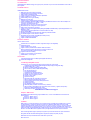
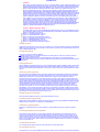
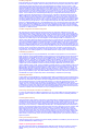
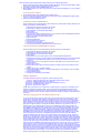
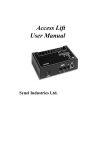
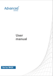
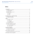
GO Software Pty Limited
Map: 27 Tacoma Blvd, Pasadena SA 5042
Phn: 0403-063-991
Fax: (08) 8219-0105
ABN: 54-008-044-906
ACN: 008-044-906
Eml: [email protected] Web: www.gosoftware.com.au
Intel Embedded Server RAID Technology: USER'S GUIDE - December 2005
Chapter 1, Overview, provides an overview of features and benefits of the Embedded Server RAID Technology.
Chapter 2, RAID Levels, describes the RAID levels supported.
Chapter 3, BIOS Configuration Utility, explains how to configure SATA and arrays, assign RAID levels, plan the array
configuration, optimize storage, and use the IDE Setup Utility.
Chapter 4, Operating System Installation, contains the procedures for installing the Windows* 2000, 2003, and XP, Red
Hat* Linux, SuSE* Linux, and Novell NetWare* operating systems when using the Embedded SATA Software RAID
Technology.
Chapter 5, Spy Service, describes the Spy Service program, which looks for errors, failed drives, and status changes in
the hard drives.
Chapter 6, Troubleshooting, describes the problems you might encounter and suggests solutions.
1.1 RAID Benefits
1.1.1 Improved I/O
1.1.2 Increased Reliability
1.2 Product Features
1.2.1 SATA Ports
1.2.2 BIOS Features
1.2.3 Driver Features
1.2.4 Manageability/Disk Console
2.1 RAID 0
2.2 RAID 1
2.3 RAID 10
3.1 Configuring Arrays
3.2 Configuration Strategies
3.3 Assigning RAID Levels
3.4 Performing a Quick Configuration
3.5 Configuring Arrays and Logical Drives
3.5.1 Starting the BIOS Configuration Utility
3.5.2 Selecting a Configuration Method
3.5.3 Configuring Physical Arrays and Logical Drives
Physical Drive Parameters
Logical Drive Parameters
Easy Configuration
New Configuration and View/Add Configuration
3.5.4 Initializing Logical Drives
3.6 Rebuilding Failed Disks
3.6.1 Inserting a Previously Removed Drive from a RAID 1 Array
3.7 Checking Data Consistency
3.8 Using a Pre-loaded System Drive
4.1 Windows 2000/2003/XP Driver Installation
4.1.1 Updating the Windows 2000/2003/XP Driver
4.1.2 Confirming the Windows 2000/2003/XP Driver Installation
5.1 Starting or Stopping Spy Service under Windows 2000, XP, or 2003
5.2 Installing Spy Service under Linux
5.3 Installing and Running Spy Service under Novell NetWare
5.4 Uninstalling Spy Service
5.5 Spy Service Icon
6.1 Problems and Suggested Solutions
3.1 Physical Drives Required per RAID Level
3.2 Physical Drives Required per RAID Level
3.3 Logical Drive Parameters and Descriptions
6.1 Problems and Suggested Solutions
3.1 Configuration Menu Screen
3.2 Logical Drive Configuration Screen
3.3 Logical Drive Submenu
5.1 Control Panel Screen
Chapter 1: Overview
This manual describes the Intel Embedded Server RAID Technology. This chapter provides an overview of this product and
contains the following sections:
Section 1.1, "RAID Benefits," page 1-1
Section 1.2, "Product Features," page 1-2
The Embedded Server RAID Technology supports four Serial ATA ports, providing a cost-effective way to achieve higher transfer
rates and reliability. Embedded Server RAID Technology supports
RAID level 0 data striping for improved performance
RAID level 1 data mirroring for improved data reliability
RAID level 10 data striping and mirroring for high data transfer rates and data redundancy
1.1 RAID Benefits
RAID has gained popularity because it can improve I/O performance or increases storage subsystem reliability. RAID 0 provides
better performance, while RAID 1 provides better reliability through fault tolerance and redundant data storage. RAID 10 combines
both striping and mirroring to provide high data transfer rates and data redundancy.
1.1.1 Improved I/O
Although hard drive capabilities have improved drastically, actual performance has improved only three to four times in the last
decade. Computing performance has improved over 50 times during the same time period. RAID 0 and RAID 10 allow you to
access several disks simultaneously.
1.1.2 Increased Reliability
The electromechanical components of a disk subsystem operate more slowly, require more power, and generate more noise and
vibration than electronic devices. These factors reduce the reliability of data stored on disks. RAID 1 and RAID 10 systems improve
data storage reliability and fault tolerance compared to single-drive computers. The additional drive in each RAID 1 array makes it
possible to prevent data loss from a hard drive failure. You can reconstruct missing data from the remaining data drive to a
replacement drive.
1.2 Product Features
1.2.1 SATA Ports
The Embedded Server RAID Technology can support up to six ports. Refer to your server board documentation for the number of
ports supported.
1.2.2 BIOS Features
The BIOS features include
RAID support before the operating system loads
automatic detection and configuration of disk drives
ability to handle configuration changes
support for Interrupt 13 and Enhanced Disk Drive Specification
support for RAID levels 0, 1, and 10
special handling of error log and rebuilding
ROM option size of 64 Kbyte
automatic resume of rebuilding and check consistency
support for BIOS Boot Specification (BBS) (If available in system BIOS, this allows the user to select the adapter from
which to boot. Specification v1.01, January 11, 1996)
co-existence with SCSI and CD devices
48-bit LBA support for read, write, and cache flush functions
independent stripe size configuration on each logical drive
ability to select a logical drive as boot device
support for power-on self test (POST) Memory Management (PMM) for the BIOS memory requirement (Specification v1.01,
November 21, 1997)
enhanced disk drive support (Specification 2.9, revision 08, March 12, 1998)
Industry-standard EBDA
Self-monitoring analysis and reporting technology (S.M.A.R.T.) notification at POST
run-time BIOS support for device insertion or removal
independent support for WC, RC, and UDMA (direct memory access)
support for Stop On Error during bootup
support to disable/enable BIOS state
1.2.3 Driver Features
The driver features include
special interface for configuration information, configuration changes, and manageability
optimized disk access
support for RAID levels 0, 1, and 10
support for Stand-by and Hibernation in Windows 2000, XP, and 2003
Note: The following items require Spy Service to be running in order to work.
error logging in the operating system event log and on disks
support for online mirror rebuilding
support for check consistency for mirrored disks
bootable RAID 0, 1, and 10 support
1-4 Overview
customized messages specific for OEM (original equipment manufacturer)
soft bad block management
1.2.4 Manageability/Disk Console
The features you can use to manage the logical and physical disks in the system include
configuration information display (in BIOS Configuration Utility and Hyper Configuration Utility)
support for RAID levels 0, 1, and 10
online mirror rebuilding (in BIOS Configuration Utility)
online consistency checks (in BIOS Configuration Utility)
array management software
error logging and notification
support for power management features
support for hot device insertion and removal
automatic resume of rebuilding on restart
support for manual rebuild
physical drive roaming
independent stripe size configuration per logical drive
ability to create up to eight logical drives per array
auto-configuration support of newly added physical drive
support for hotspares
support for disk coercion
array initialization support (fast and normal)
offline data (RAID 1) verfication with auto-recovery mechanism
ability to prioritize configurable tasks (for online rebuild, check consistency, migration, and expansion)
logical drive availability immediately after creation
variable stripe size options from 8 Kbyte to 128 Kbyte
Embedded Server RAID Technology 2-1
Chapter 2: RAID Levels
Intel Embedded Server RAID Technology supports RAID levels 0, 1, and 10. These RAID levels are discussed in the
following sections:
Section 2.1, "RAID 0," page 2-1
Section 2.2, "RAID 1," page 2-2
Section 2.3, "RAID 10," page 2-3
2.1 RAID 0
RAID 0 (Figure 2.1) provides disk striping across all configured drives in the RAID subsystem. RAID 0 does not provide
any data redundancy, but does offer the best performance of any RAID level. RAID 0 breaks up data into smaller
segments, then stripes the data segments across each drive in the array as shown in Figure 2.1. The size of each data
segment is determined by the stripe size parameter, which is set during the creation of the RAID set. By breaking up a
large file into smaller segments, Embedded Server RAID Technology can use both IDE ports and drives to read or write the
file faster. This makes RAID 0 ideal for applications that require high bandwidth but do not require fault tolerance.
Uses: Provides high data throughput, especially for large files. Any environment that does not require fault tolerance.
Strong Points: Provides increased data throughput for large files. No capacity loss penalty for parity.
Weak Points: Does not provide fault tolerance. All data lost if any drive fails.
Drives: One to two
2-2 RAID Levels
2.2 RAID 1
RAID 1 (Figure 2.2) duplicates all data from one drive to a second drive. RAID 1 provides complete data redundancy, but at
the cost of doubling the required data storage capacity. Figure 2.2RAID 1 Array Segment 1Segment 3Segment 5Segment
2Segment 4Segment 6Segment 7Segment 8 Uses Databases or any other mission critical environment that requires fault
tolerance. Strong Points Provides complete data redundancy. RAID 1 is ideal for any application that requires fault
tolerance. Weak Points Requires twice as many hard drives. Performance is impaired during drive rebuilds. Drives Two
Segment 1Segment 2Segment 3Segment 1 DuplicatedSegment 2 DuplicatedSegment 3 DuplicatedSegment 4Segment 4
Duplicated RAID 10 2-3 2.3RAID 10 RAID 10 is a combination of RAID 1 and RAID 0. RAID 10 has mirrored drives. It breaks
up data into smaller blocks, then stripes the blocks of data to each RAID 1 RAID set. Each RAID 1 RAID set then duplicates
its data to its other drive. The size of each block is determined by the stripe size parameter, which is set during the
creation of the RAID set. RAID 10 can sustain one drive failure in each array while maintaining data integrity. Figure 2.3
shows a RAID 10 array with four disk drives. Figure 2.3RAID 10 Array Uses Works best for data storage that must have
100% redundancy of RAID 1 (mirrored arrays) and that also needs the enhanced I/O performance of RAID 0 (striped
arrays). RAID 10 works well for medium-sized databases or any environment that requires a higher degree of fault
tolerance and moderate to medium capacity. Strong Points Provides both high data transfer rates and complete data
redundancy. Weak Points Requires twice as many drives.. Drives 4 RAID 1Disk 2Disk 1Disk 4Disk 3RAID 1RAID 0Segment
1Segment 3Segment 5Segment 1Segment 3Segment 5Segment 2Segment 4Segment 6Segment 6Segment 2Segment
4Segment 6 2-4 RAID Levels Embedded Server RAID Technology 3-1
Chapter 3: BIOS Configuration Utility
This chapter explains how to configure Intel Embedded Server RAID Technology and arrays, assign RAID levels, plan the
array configuration, optimize storage, and use the IDE Setup Utility. This information is presented in the following sections:
Section 3.1, "Configuring Arrays," page 3-1
Section 3.2, "Configuration Strategies," page 3-2
Section 3.3, "Assigning RAID Levels," page 3-2
Section 3.4, "Performing a Quick Configuration," page 3-3
Section 3.5, "Configuring Arrays and Logical Drives," page 3-4
Section 3.6, "Rebuilding Failed Disks," page 3-10
Section 3.7, "Checking Data Consistency," page 3-11
Section 3.8, "Using a Pre-loaded System Drive," page 3-12
3.1Configuring Arrays
Configure the physical disk drives in arrays. An array can consist of one to four physical disk drives, depending on the RAID level.
A RAID 0 array can consist of one to four physical drives, while a RAID 1 array consists of two. A RAID 10 array consists of four
drives. 3-2 BIOS Configuration Utility
3.2Configuration Strategies
You have two choices when creating a RAID array.
Maximizing Fault Tolerance You can maximize fault tolerance to protect against loss of data by using mirroring. Use mirror
configuration (RAID 1) to attain this objective.
Maximizing Logical Drive Performance You can maximize logical drive performance by using striping. Select striping
configuration (RAID 0) to attain this objective. RAID 10 combines both striping and mirroring to provide high data transfer rates and
data redundancy.
3.3Assigning RAID Levels
Only one RAID level can be assigned to each array. Table 3.1 displays the drives required per RAID level. Table 3.1Physical Drives
Required per RAID Level RAID Level Minimum Number of Physical Drives Maximum Number of Physical Drives 0 One Four 1 Two
Two 10 Four Four Performing a Quick Configuration 3-3 The factors you need to consider when selecting a RAID level are listed in
Table 3.2.
3.4Performing a Quick Configuration
This section provides quick installation steps for users that are familiar with configuration utilities and tools. Refer to Section 3.5,
"Configuring Arrays and Logical Drives," for detailed configuration instructions. To ensure best performance, select the optimal
RAID level for the logical drive you create. Perform the following steps to configure arrays and logical drives using the
Configuration Utility (CU): Step 1.Boot the system. Step 2.Start the CU by pressing . Step 3.Select a configuration method. Step
4.Create arrays using the available physical drives. Table 3.2Physical Drives Required per RAID Level Level Description and Use
Pros Cons Number of Drives Fault Tolerant 0 Data divided in blocks and distributed sequentially (pure striping). Use for non-critical
data that requires high performance. High data throughput for large files No fault tolerance. Data is lost if a drive fails. One to four
No 1 Data duplicated on another disk (mirroring). Use for read-intensive, fault-tolerant systems. 100 percent data redundancy,
providing fault tolerance. More disk space required. Reduces usable disk space to the size of the smallest drive. Reduced
performance during rebuilds. Two Yes 10 A combination of RAID 1 (data mirroring) and RAID 0 (data striping). Use for mediumsized databases or any environment that requires a higher degree of fault tolerance and moderate to medium capacity. Provides
both high data transfer rates and complete data redundancy. More disk space required. Reduces usable disk space to the size of
the smallest drive. Reduced performance during rebuilds. Four Yes 3-4 BIOS Configuration Utility Step 5.Define the logical drive(s)
using the space in the arrays. Step 6.Initialize the new logical drive(s).
3.5Configuring Arrays and Logical Drives
This section provides detailed instructions for configuring the logical disks and arrays.
3.5.1Starting the BIOS Configuration Utility
During bootup, the following BIOS banner displays the following: Press Ctrl-E to run LSI Logic Embedded SATA RAID Setup Utility
Hold down the key while you press . The main menu for the utility displays.
3.5.2Selecting a Configuration Method
Section 3.5.3, "Configuring Physical Arrays and Logical Drives," provides detailed instructions for using each configuration
method.
3.5.3Configuring Physical Arrays and Logical Drives
This subsection provides instructions for using the Easy Configuration, New Configuration, and View/Add Configuration to
configure arrays and logical drives. LSI Logic recommends using drives with the same capacity in a specific array. If you use
drives with different capacities in an array, the CU treats all these drives as if they have the capacity of the smallest drive. The
number of physical drives in a specific array determines the possible RAID levels that you can implement with the array. RAID 0
requires one to four physical drives, RAID 1 requires two physical drives, and RAID 10 requires four physical drives. Configuring
Arrays and Logical Drives 3-5
3.5.3.1Physical Drive Parameters
You can change the write policy and read policy in the physical drives, but not the logical drives.
3.5.3.2Logical Drive Parameters
For the logical drive you can change the RAID level and stripe size. Table 3.3 contains descriptions of the logical drive parameters.
3.5.3.3Easy Configuration
In Easy Configuration, the CU associates each hard drive with a single logical drive. If logical drives have already been configured,
the CU does not change their configuration. Perform the following steps to create arrays using Easy Configuration: Step 1.Select
Configuration? Easy Configuration at the main menu. The Configuration Menu screen displays, as shown in Figure 3.1. Table
3.3Logical Drive Parameters and Descriptions Parameter Description RAID Level The number of physical drives in a specific array
determines the RAID levels that can be implemented with the array. RAID 0 requires one or two physical drives. RAID 1 requires
exactly two physical drives. RAID 10 requires exactly four physical drives. Stripe Size The stripe size parameter specifies the size
of the segment written to each disk in a RAID configuration. You can set the stripe size to 4, 8, 16, 32, 64, or 128 Kbytes. The
default is 64 Kbytes. A larger stripe size produces higher read performance. If your computer regularly performs random read
requests, choose a smaller stripe size. 3-6 BIOS Configuration Utility Figure 3.1Configuration Menu Screen Step 2.Press the
spacebar to associate the selected physical drives with the current array. The indicator for the selected drives changes from
READY to ONLIN A[array number]-[drive number]. For example, ONLIN A1-3 means array 1 with disk drive 3. Step 3.Press after
you finish creating the current array. Step 4.Press to select configurable arrays. Step 5.Press the spacebar to select the array.
The logical drive configuration screen displays, as shown in Figure 3-2. The logical drive configuration screen displays the logical
drive number, RAID level, logical drive size, the number of stripes in the physical array, the stripe size, and the state of the logical
drive. Configuring Arrays and Logical Drives 3-7 Figure 3.2Logical Drive Configuration Screen Step 6.Set the RAID level for the
logical drive by highlighting RAID and pressing . The available RAID levels for the current logical drive display. Step 7.Select a RAID
level and press . Step 8.Set the RAID logical drive size and stripe size. Step 9.When you have defined the current logical drive,
select Accept and press . Step 10.Repeat step 7 to step 10 to configure additional logical drives. Step 11.Save the configuration
when prompted and press to return to the Management Menu. Step 12.Initialize the logical drives. Refer to Section 3.5.4, "Initializing
Logical Drives," for detailed instructions.
3.5.3.4New Configuration and View/Add Configuration
New Configuration and View/Add Configuration associate logical drives with partial and/or multiple physical arrays. New
Configuration deletes the existing configuration and replaces it with the configuration that you specify. View/Add Configuration
lets you display or modify an existing configuration. Caution: The New Configuration option erases the existing configuration data
when you save the new array 3-8 BIOS Configuration Utility configuration. If you do not want to delete the existing configuration
data, use View/Add Configuration. Perform the following steps to configure a disk array using New Configuration or View/Add
Configuration: Step 1.Select Configure? View/Add Configuration from the CU Management Menu. The CU displays an array
selection window. Step 2.Select the physical drives to include in the array by pressing the arrow keys to select specific physical
drives. Step 3.Press the spacebar to associate the selected physical drive with the current array. The indicator for the selected
drive changes from READY to ONLIN A[array number]-[drive number]. For example, ONLIN A1-3 means array 1 with disk drive 3.
Step 4.Press after you finish creating the current array. Step 5.Press to configure logical drives. Step 6.Set the RAID level for the
logical drive by highlighting RAID and pressing . A list of the available RAID levels for the current logical drive appears. Step 7.Set
the logical drive size by moving the cursor to Size and pressing . By default, the logical drive size associates the available space in
the array(s) with the current logical drive. Step 8.Set the stripe size. Step 9.After you define the current logical drive, select
Accept and press . Step 10.Save the configuration when the CU prompts you to do so. Step 11.Initialize the logical drives you
configured. Section 3.5.4, "Initializing Logical Drives," provides detailed instructions. Configuring Arrays and Logical Drives 3-9
3.5.4Initializing Logical Drives
You can initialize the logical drives using individual initialization, which initializes a single logical disk. There are two methods to
initialize a logical drive using the individual initialization procedure using the CU. For the first method, perform the following steps to
initialize a logical drive using the Initialize menu. Step 1.On the Management Menu, select Initialize. Step 2.Use the space bar to
highlight the logical drive to initialize. The logical drive name is highlighted in yellow. To de-select the logical drive, press the space
bar again. Step 3.Press . Step 4.Select Yes at the prompt and press to begin the initialization. A graph shows the progress of the
initialization until it is complete. Step 5.After the initialization is complete, press to return to previous menus. If you press while
initialization is in progress, the following options display: ?Stop: The CU stores the percentage of the initialization already
completed. When you restart initialization, it continues from the last percentage completed rather than from zero percent. ?
Continue: initialization continues normally. ?Abort: The initialization is completely aborted. If you restart initialization, it begins at zero
percent. For the second method, perform the following steps to initialize a logical drive using the Objects menu. Step 1.From the
Management Menu, select Objects? Logical Drive submenu, as shown in Figure 3.3. The configured logical drives display. 3-10
BIOS Configuration Utility Figure 3.3Logical Drive Submenu Step 2.Select a logical drive, if there is more than one configured. and
press . Step 3.Select Initialize from the submenu and press . Step 4.Select Yes at the prompt and press . The CU displays a bar
graph showing the initialization progress. Step 5.When initialization completes, press to return to the previous menu. If you press
while initialization is in progress, the options Stop, Continue, and Abort display, as explained on the previous page.
3.6Rebuilding Failed Disks
A manual rebuild is used to rebuild failed drives. The CU allows manual rebuild for an individual drive. Perform the following steps
to rebuild a drive: Step 1.Select Rebuild from the CU Management Menu. The CU displays a device selection window that marks the
failed drives with FAIL indicators. Step 2.Press the arrow keys to highlight the drive to be rebuilt. Step 3.Press the spacebar to
select the highlighted physical drive for rebuild. Checking Data Consistency 3-11 Step 4.After selecting the physical drive, press
and select Yes at the confirmation prompt. The indicators for the selected drive changes to REBLD. Step 5.When rebuild is
complete, press any key to continue. Step 6.Press to display the Management Menu. A second way to perform a manual rebuild on
an individual drive is as follows: Step 1.Select the option from the CU? Objects? Physical Drive submenu. Step 2.Press the arrow
keys to select the physical drive to be rebuilt and press . Step 3.Select the Rebuild option from the action menu and respond to the
confirmation prompt. Step 4.When rebuild completes, press any key to display the previous menu.
3.6.1Inserting a Previously Removed Drive from a RAID 1 Array
If you have auto-rebuild selected in the BIOS, the rebuild begins as soon as you enter the BIOS CU. If auto-rebuild is disabled, you
can choose whether to rebuild. If you decide to rebuild the drive, follow the procedure in Section 3.6, "Rebuilding Failed Disks,"
page 3-10.
3.7Checking Data Consistency
The Check Consistency feature verifies the correctness of the redundancy data in the selected logical drive and causes the CU to
automatically correct any differences found in the data. This feature can be used only on a RAID 1 logical drive, to verify the data
consistency between the mirrored physical drives. When a data inconsistency is found, the CU can either only report the
inconsistency or report and fix the inconsistency, depending upon the option selected in Adapter settings. In the CU, perform the
following steps to check consistency: 3-12 BIOS Configuration Utility Step 1.On the Management Menu select Check Consistency
and press . The configured logical drives display. Step 2.Use the space bar to select a logical drive to check for consistency. Note
that the logical drive should be at a RAID 1 level to start check consistency. If you select a RAID 0 logical drive, a message
displays stating that a check consistency cannot be performed. To de-select a logical drive, press the space bar again. Step
3.Press . Step 4.At the prompt, select Yes to start check consistency and press . If you press while the check consistency is in
progress, the following options display: ?Stop: The CU stores the percentage of the check consistency already completed. When
you restart the check consistency, it continues from the last percentage completed rather than from zero percent. ?Continue:
Check consistency continues normally. ?Abort: The check consistency is completely aborted. If you restart check consistency, it
begins at zero percent.
3.8 Using a Pre-loaded System Drive
Loading an operating system on a stand-alone drive and then attempting to add that drive to a RAID array will cause a blue screen
upon reboot. Embedded Server RAID Technology 4-1
Chapter 4: Operating System Installation
This chapter contains the procedures for installing the Windows* 2000, 2003, and XP, Red Hat* Linux, SuSE* Linux, and Novell
NetWare* operating systems when using the Intel Embedded Server RAID Technology. The chapter contains the following
sections:
4.1Windows 2000/2003/XP Driver Installation
Perform the following steps to install the Windows 2000 or 2003 driver onto the RAID-configured drives.
1. Boot the system with the Windows 2000 or 2003 Boot Installation CD or diskette. The following message displays: Setup is
inspecting your computers hardware configuration. Next, a prompt displays.
2. At the prompt, press [F6] to install the RAID/SCSI adapter driver.
3. When installation prompts for a key after copying some files, press [S] to add the SATA RAID driver. You are prompted for
the driver diskette.
4-2 Operating System Installation
4. Insert the Embedded SATA Software RAID driver floppy diskette and press .
5. Scroll down the list until the appropriate selection for your system which contains the Embedded SATA Software RAID
and for your operating system displays, then click .
6. Continue with the normal installation procedure.
4.1.1Updating the Windows 2000/2003/XP Driver
Perform the following steps to update the Windows 2000 or 2003 driver or install the Windows 2000 or 2003 driver into an
existing system booted from a standard IDE drive.
1.
2.
3.
4.
5.
6.
7.
8.
9.
10.
11.
12.
13.
Click the Windows Start button. The Windows menu displays.
Select Settings. The Settings menu displays to the right.
Click Control Panel. The Control Panel window displays.
Select Adapters.
Select the Drivers tab.
Scroll down the list until the appropriate selection for your system which contains the Embedded SATA Software
RAID and for your operating system displays, then click .
Select it, then remove it by clicking the Remove button.
Click the Add button.
Select the Have Disk button.
Insert the diskette into the floppy drive.
Select drive letter A: and click on .
Select LSI Logic Embedded SATA Controller and click OK.
After Windows NT or Windows 2000 copies the driver, reset the system.
4.1.2Confirming the Windows 2000/2003/XP Driver Installation
Perform the following steps to confirm that the Windows 2000, 2003, or XP driver is installed properly.
1.
2.
3.
4.
5.
6.
7.
8.
9.
10.
11.
12.
13.
14.
Click the Windows Start button. The Windows menu displays.
Select Settings. The Settings menu displays to the right.
Click Control Panel. The Control Panel window displays.
Select Adapters.
Select the Drivers tab. The controller appears in the list as LSI Logic Embedded SATAController.
Select the Devices tab. One or more entries display as LSI Logic Embedded SATA #xx under LSI Logic Embedded
SATA Controller. The Intel RAID controller displays. There is one driver per controller to remove or add.
Press twice.
Select Continue and press . The storage devices and driver names display so you can match the drivers to the
hardware devices.
Select Continue and press .
Select Continue and press again. The message "Loading driver" displays, then the screen Create Sys Volume
displays.
Select Create and press . The Main Menu displays.
Select Continue Installation and press . The File Copy Status displays to confirm that the driver files are installed,
then a GUI prompt displays.
Select Customized and press .
Continue the normal operating system installation.
Chapter 5: Spy Service
This chapter describes the Spy Service program and contains the following sections
Section 5.1, "Starting or Stopping Spy Service under Windows 2000, XP, or 2003," page 5-1
Section 5.2, "Installing Spy Service under Linux," page 5-3
Section 5.3, "Installing and Running Spy Service under Novell NetWare," page 5-3
Section 5.4, "Uninstalling Spy Service," page 5-4
Section 5.5, "Spy Service Icon," page 5-4
The Spy Service program looks for errors, failed drives, and status changes. It can mark drives as failed after the error
threshold is reached and start automatic rebuilds. It runs in the background of the Embedded SATA Console. When
operating under Windows, Spy enables the self-monitoring analysis and reporting technology (S.M.A.R.T.) on all of the
hard drives at startup and polls for any status changes in the drives every 60 minutes. S.M.A.R.T. monitors hard drives for
drive failures.
5.1Starting or Stopping Spy Service under Windows 2000, XP, or 2003
You can use the Control Panel to access the option to start or stop Spy Service. Perform the following steps to start or
stop Spy Service. Step 1.Click on Start > Settings > Control Panel. The screen shown in Figure 5.1 displays. 5-2 Spy
Service Figure 5.1Control Panel Screen Step 2.Click on Administrative Tools? Services icon? Spy Ser. A dialog window
displays with the start and stop options. Step 3.Click on the Start or Stop button. This starts or stops the Spy Service
program, depending on your selection. Note: You can right-click on the Spy Service icon and select "Stop Spy" to stop the
Spy program. The Spy icon displays on the right side of the taskbar. See Section 5.5, "Spy Service Icon" for more
information about the icon. Installing Spy Service under Linux 5-3 5.2Installing Spy Service under Linux Perform the
following steps to install Spy Service under Linux. Spy Service runs in the background after installation. Note: You must
have "GNOME" libraries installed before you install Spy Service. Step 1.Log in to GUI mode. Step 2.At the Linux prompt,
type: $ rpm -ivh spy.x.x.x.i386.rpm Step 3.Press . The rpm is extracted and the necessary files installed and started,
5.3Installing and Running Spy Service under Novell NetWare Perform the following steps to install Spy Service under
Novell NetWare. Step 1.Unzip the file Spy-x.x Novell.zip from the installation CD to a floppy diskette in the A:/ drive. Step
2.Go to the Novell server prompt and type: :a:install Messages display when the files are copied. Step 3.Reboot to
complete the installation. Step 4.After reboot, you can type the following to see whether Spy is running: :modules spy
Step 5.Press . The information shows whether Spy is running. 5-4 Spy Service 5.4Uninstalling Spy Service Perform the
following steps to uninstall Spy Service. Step 1.Stop the Spy Service program. See "Section 5.1, "Starting or Stopping Spy
Service under Windows 2000, XP, or 2003" for instructions on stopping Spy Service. Step 2.Click on Start? Control Panel.
The Control Panel displays. Step 3.Click on Add/Remove Programs. The list of currently installed programs displays. Step
4.Click on the Spy Service program and select Remove. 5.5Spy Service Icon The icon for the Spy Service displays in the
bottom right corner of the Embedded Server RAID Technology Console screen (in the tray bar). The icon is a round figure
wearing sunglasses. The icon is color-coded. Green means that there are no problems. Yellow means that there is a
rebuild in progress or there are media errors and a possible drive failure. Red warns of a critical problem that could cause
the system to fail. Hold the cursor over the icon ("mouseover") and a short text displays that describes the system status.
Right click on the icon and the following options display: Stop monitor media error The program stops searching for media
errors. Erase error log The program deletes the errors that were recorded on the error log. Stop Spy This stops the
program and deletes the icon from the taskbar. You can start the program again using the instructions in "Section 5.1,
"Starting or Stopping Spy Service under Windows 2000, XP, or 2003" Spy Service Icon 5-5 Do the following to place the
Spy icon on the Taskbar when operating under Windows 2000: Click on Start? Programs? MegaRAID IDE? MegaRAID IDE
Spy. This places the Spy icon on the Taskbar. Note: The Spy icon displays on the Taskbar automatically under the
Windows Server 2003 operating system. 5-6 Spy Service Embedded Server RAID Technology 6-1
Chapter 6: Troubleshooting
6.1Problems and Suggested Solutions
Table 6.1 describes possible problems you might encounter, along with suggested solutions. Table 6.1Problems and
Suggested Solutions Problem Suggested Solution Drives are not detected OR The system hangs when the adapter ROM
for Embedded SATA Software RAID scans the SATA ports.
Make sure that the cable ends are connected properly.
Make sure that the power cables to the drives are connected properly.
Change cables.
If everything fails, change the drive(s).
Operating system does not boot.
Check the system BIOS configuration for PCI interrupt assignments. Make sure some Interrupts are assigned for PCI. Make
sure that you have properly selected the Boot Device in the system BIOS setup (CMOS Setup). An error occurs while
reading the configuration data on a drive. The drive is bad and needs to be replaced. There is no existing RAID
configuration on any of the drives connected to the system and the message "Intel Embedded Server RAID Technology
Not Configured" displays. Press any key to enter the BIOS Configuration Utility (Ctrl-E), then select a configuration method
and configure the drive(s). BIOS reports that a mirrored array is in degraded mode. Make sure all physical drives are
properly connected and are powered on. Reconnect, replace, or rebuild any drive that has failed.
6-2 Troubleshooting
One of the hard drives in a mirrored (RAID 1) array has failed. Replace the failed drive with another drive that has the
same or greater capacity. You insert a new drive with no configuration into the slot which is already part of a mirrored
(RAID 1) array. Press any key to enter the BIOS Configuration Utility (Ctrl-E) to configure the new drive. Mark the drive as
one of the following:
Failed - If the AutoRebuild option is disabled in the configuration utility
Rebuilding - If the AutoRebuild option is enabled in the configuration utility
You insert a new drive with no configuration into the slot which is already part of a striped (RAID 0) array or there is a
striped (RAID 0) array by itself in the system. Press any key to enter the BIOS Configuration Utility (Ctrl-E) to configure the
new drive.
© Copyright 2014 by GO Software Pty Limited