1
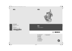
OBJ_DOKU-19995-001.fm Page 1 Thursday, November 24, 2011 11:32 AM Robert Bosch GmbH Power Tools Division 70745 Leinfelden-Echterdingen Germany GKF 600 Professional www.bosch-pt.com 2 610 007 835 (2011.11) O / 179 UNI de en fr es pt it nl Originalbetriebsanleitung Original instructions Notice originale Manual original Manual original Istruzioni originali Oorspronkelijke gebruiksaanwijzing da Original brugsanvisning sv Bruksanvisning i original no Original driftsinstruks fi Alkuperäiset ohjeet el tr pl cs sk hu ru Ðñùôüôõðï ïäçãéþí ÷ñÞóçò Orijinal işletme talimat Instrukcja oryginalna Původní návod k používání Pôvodný návod na použitie Eredeti használati utasítás Îðèãèíàëüíîå ðóêîâîäñòâî ïî ýêñïëóàòàöèè uk Îðèã³íàëüíà ³íñòðóêö³ÿ ç åêñïëóàòàö³¿ ro Instrucţiuni originale bg Îðèãèíàëíà èíñòðóêöèÿ sr sl hr et lv lt ar fa Originalno uputstvo za rad Izvirna navodila Originalne upute za rad Algupärane kasutusjuhend Instrukcijas oriģinālvalodā Originali instrukcija ΔϴϠλϷ ϞϴϐθΘϟ ΕΎϤϴϠόΗ ̶Ϡλ έΎ̯ ίήσ ̵ΎϤϨϫέ OBJ_BUCH-1137-001.book Page 3 Thursday, November 24, 2011 11:34 AM 3| 1 11 10 2 9 8 7 6 5 3 4 12 GKF 600 Professional 2 610 007 835 | (24.11.11) Bosch Power Tools OBJ_BUCH-1137-001.book Page 4 Thursday, November 24, 2011 11:34 AM 4| A B 1 5 2 10 13 14 C D 9 9 5 5 4 15 E 1 2 F 10 3 10 8 2 610 007 835 | (24.11.11) Bosch Power Tools OBJ_BUCH-1137-001.book Page 5 Thursday, November 24, 2011 11:34 AM 5| G H 16 17 18 I J 23 16 2 19 20 22 21 K 10 L 1 24 24 10 2 610 007 835 | (24.11.11) Bosch Power Tools OBJ_BUCH-1137-001.book Page 6 Thursday, November 24, 2011 11:34 AM 6| M N 24 25 26 25 27 28 29 30 O 31 10 2 610 007 835 | (24.11.11) Bosch Power Tools OBJ_BUCH-1137-001.book Page 14 Thursday, November 24, 2011 11:34 AM 14 | English f Use the power tool, accessories and tool bits etc. in accordance with these instructions, taking into account the working conditions and the work to be performed. Use of the power tool for operations different from those intended could result in a hazardous situation. Service f Have your power tool serviced by a qualified repair person using only identical replacement parts. This will ensure that the safety of the power tool is maintained. Safety Warnings for Routers f Hold power tool by insulated gripping surfaces, because the cutter may contact its own cord. Cutting a “live” wire may make exposed metal parts of the power tool “live” and shock the operator. f Use clamps or another practical way to secure and support the workpiece to a stable platform. Holding the work by your hand or against the body leaves it unstable and may lead to loss of control. f The allowable speed of the router bit must be at least as high as the maximum speed listed on the power tool. Accessories that rotate faster than permitted can be destroyed. f Router bits or other accessories must fit exactly in the tool holder (collet) of your machine. Routing bits that do not fit precisely in the tool holder of the machine rotate irregularly, vibrate heavily and can lead to loss of control. f Apply the machine to the workpiece only when switched on. Otherwise there is danger of kickback when the cutting tool jams in the workpiece. f Never cut over metal objects, nails or screws. The router bit can become damaged and lead to increased vibrations. f Use suitable detectors to determine if utility lines are hidden in the work area or call the local utility company for assistance. Contact with electric lines can lead to fire and electric shock. Damaging a gas line can lead to explosion. Penetrating a water line causes property damage or may cause an electric shock. f Do not use blunt or damaged router bits. Blunt or damaged router bits cause increased friction, can become jammed and lead to imbalance. f Always wait until the machine has come to a complete stop before placing it down. The tool insert can jam and lead to loss of control over the power tool. Products sold in GB only: Your product is fitted with an BS 1363/A approved electric plug with internal fuse (ASTA approved to BS 1362). If the plug is not suitable for your socket outlets, it should be cut off and an appropriate plug fitted in its place by an authorised customer service agent. The replacement plug should have the same fuse rating as the original plug. The severed plug must be disposed of to avoid a possible shock hazard and should never be inserted into a mains socket elsewhere. Products sold in AUS and NZ only: Use a residual current device (RCD) with a rated residual current of 30 mA or less. 2 610 007 835 | (24.11.11) Product Description and Specifications Read all safety warnings and all instructions. Failure to follow the warnings and instructions may result in electric shock, fire and/or serious injury. While reading the operating instructions, unfold the graphics page for the machine and leave it open. Intended Use The machine is intended for routing grooves, edges, profiles and elongated holes as well as for copy routing in wood, plastic and light building materials, while resting firmly on the workpiece. Product Features The numbering of the components shown refers to the representation of the power tool on the graphic pages. 1 Motor unit 2 Routing base 3 Thumbwheel for depth-of-cut fine adjustment 4 Router bit* 5 Tightening nut with collet 6 Guide plate 7 Base plate 8 Scale for depth-of-cut 9 Spindle lock button 10 Clamping lever 11 On/Off switch 12 Handle (insulated gripping surface) 13 Collet 14 Tool holder 15 Open-end spanner (17 mm) 16 Knurled screw for attachment of side stop 17 Parallel guide 18 Wing bolt for parallel guide 19 Roller guide 20 Wing bolt for locking of the horizontal alignment 21 Wing bolt for horizontal alignment of the roller guide 22 Roller 23 Base cover sleeve* 24 Tilt base* 25 Wing bolt for angle adjustment 26 Scale for routing angle adjustment 27 Handle of the guide plate* 28 Extraction hood* 29 Extraction adapter* 30 Side-handle subbase* 31 Nut for adjustment of the tensioning force *Accessories shown or described are not part of the standard delivery scope of the product. A complete overview of accessories can be found in our accessories program. Bosch Power Tools OBJ_BUCH-1137-001.book Page 15 Thursday, November 24, 2011 11:34 AM English | 15 Technical Data Laminate trimmer GKF 600 Professional 3 601 F0A 1.. Article number Rated power input No-load speed Tool holder Weight according to EPTA-Procedure 01/2003 Protection class W min-1 mm inch kg GKF 600 Professional 3 601 F0A 16. 3 601 F0A 17. 600 33000 – ¼ 1.5 /II 600 33000 6/8 – 1.5 /II The values given are valid for a nominal voltage [U] of 230 V. For different voltages and models for specific countries, these values can vary. Please observe the article number on the type plate of your machine. The trade names of the individual machines may vary. Noise/Vibration Information Measured sound values determined according to EN 60745. Typically the A-weighted noise levels of the product are: Sound pressure level 84 dB(A); Sound power level 95 dB(A). Uncertainty K =3 dB. Wear hearing protection! Vibration total values ah (triax vector sum) and uncertainty K determined according to EN 60745: ah =4.5 m/s2, K=1.5 m/s2. The vibration emission level given in this information sheet has been measured in accordance with a standardised test given in EN 60745 and may be used to compare one tool with another. It may be used for a preliminary assessment of exposure. The declared vibration emission level represents the main applications of the tool. However if the tool is used for different applications, with different accessories or poorly maintained, the vibration emission may differ. This may significantly increase the exposure level over the total working period. An estimation of the level of exposure to vibration should also take into account the times when the tool is switched off or when it is running but not actually doing the job. This may significantly reduce the exposure level over the total working period. Identify additional safety measures to protect the operator from the effects of vibration such as: maintain the tool and the accessories, keep hands warm, organise work patterns. Declaration of Conformity We declare under our sole responsibility that the product described under “Technical Data” is in conformity with the following standards or standardization documents: EN 60745 according to the provisions of the directives 2011/65/EU, 2004/108/EC, 2006/42/EC. Technical file (2006/42/EC) at: Robert Bosch GmbH, PT/ETM9, D-70745 Leinfelden-Echterdingen – Unscrew the tightening nut 5 with open-end spanner 15 Bosch Power Tools Dr. Egbert Schneider Senior Vice President Engineering Dr. Eckerhard Strötgen Engineering Director PT/ESI Robert Bosch GmbH, Power Tools Division D-70745 Leinfelden-Echterdingen 26.10.2011 Assembly Changing the Tool f Before any work on the machine itself, pull the mains plug. f It is recommended to wear protective gloves when inserting or replacing router bits. Disassembling the Routing Base (see figure A) Before a router bit can be inserted, the routing base 2 must first be removed from the motor unit 1. – Open the clamping lever 10 and turn the routing base 2 so that the mark is in line with the symbol on the motor unit 1. – Pull the motor unit upward to the stop. – Turn the motor unit in anticlockwise direction to the stop and pull it out of the routing base. Replacing the Collet (see figure B) Depending on the routing tool being used, the tightening nut with the collet 5 may need to be replaced before inserting the router bit. When the right collet for your router bit is already mounted, follow the work steps as described under “Inserting a Router Bit”. The collet 13 must have somewhat play when seated in the tightening nut. The tightening nut 5 must assemble easily. Should the tightening nut or collet be damaged, replace immediately. – Push the spindle lock button 9 and keep it pressed. If required, rotate the motor spindle by hand until it locks. turning in anticlockwise direction. 2 610 007 835 | (24.11.11) OBJ_BUCH-1137-001.book Page 16 Thursday, November 24, 2011 11:34 AM 16 | English – Release the spindle lock button. – If required, clean all parts to be mounted prior to assembling, using a soft brush or by blowing out with compressed air. – Start the new tightening nut on tool holder 14. – Hand-tighten the tightening nut. f Do not tighten the tightening nut of the collet without a router bit inserted. Otherwise the collet can be damaged. Inserting a Router Bit (see figures C–D) Depending on the application, router bits are available in the most different designs and qualities. Router bits made of high speed steel (HSS) are suitable for the machining of soft materials, e. g. softwood and plastic. Carbide tipped router bits (HM) are particularly suitable for hard and abrasive materials, e. g. hardwood and aluminium. Original router bits from the extensive Bosch accessories program are available at your specialist shop. Only use clean router bits that are in perfect condition. – Push the spindle lock button 9 and keep it pressed. If required, rotate the motor spindle by hand until it locks. – Loosen the tightening nut 5 with the open-end spanner by turning in anticlockwise direction 15. – Insert the router bit into the collet. The shank of the router bit must be immersed at least 20 mm into the collet. – Retighten the tightening nut by turning in clockwise direction. – Release the spindle lock button. f Do not tighten the tightening nut of the collet without a router bit inserted. Otherwise the collet can be damaged. Mounting the Routing Base (see figure E) For routing, the routing base 2 must be mounted on the motor unit 1 again. – Release clamping lever 10, if tightened. – Bring the two double arrows on the motor unit and the routing base 2 into alignment. – Push the motor unit into the routing base and turn the motor unit in clockwise direction until the mark points against the symbol. – Push the motor unit further into the routing base. – After mounting is completed, turn the mark on the routing base to the symbol on the motor unit. – Lock the clamping lever. f After mounting, always check if the motor unit is seated tightly in the routing base. If required, change the pre-tension of the clamping lever 10 (see “Readjusting the Clamping Lever”, page 17). Dust/Chip Extraction f Dusts from materials such as lead-containing coatings, some wood types, minerals and metal can be harmful to one’s health. Touching or breathing-in the dusts can cause allergic reactions and/or lead to respiratory infections of the user or bystanders. Certain dusts, such as oak or beech dust, are considered as carcinogenic, especially in connection with wood-treatment additives (chromate, wood preservative). Materials containing asbestos may only be worked by specialists. 2 610 007 835 | (24.11.11) – As far as possible, use a dust extraction system suitable for the material. – Provide for good ventilation of the working place. – It is recommended to wear a P2 filter-class respirator. Observe the relevant regulations in your country for the materials to be worked. Operation Adjusting the Depth-of-cut (see figure F) f The adjustment of the depth-of-cut may only be carried out when the router is switched off. For coarse adjustment of the depth-of-cut, proceed as follows: – Place the machine with the router bit mounted on the workpiece to be machined. – Release clamping lever 10, if tightened. – Turn the routing base 2 so that the mark points against the symbol and slowly lower the motor unit until the router bit touches the workpiece. – Lock the clamping lever. – Read the measuring value off the scale 8 and note it down (zeroing). Add the desired depth-of-cut to this value. – Open the clamping lever and adjust the motor unit to the calculated scale value. – Turn the routing base so that the mark points against the symbol and lock the clamping lever again. – Check the carried out depth-of-cut adjustment with a trial cut and correct it, if necessary. For fine adjustment of the depth-of-cut, proceed as follows: – With the clamping lever 10 open, turn the routing base so that the mark points against the symbol. – Adjust the desired depth-of-cut with thumbwheel 3. – Lock the clamping lever. Starting Operation f Observe correct mains voltage! The voltage of the power source must agree with the voltage specified on the nameplate of the machine. Power tools marked with 230 V can also be operated with 220 V. Switching On and Off To start the machine, set the On/Off switch 11 to I. To switch off the machine, set the On/Off switch 11 to 0. Working Advice f Protect router bits against shock and impact. Shaping or Molding Applications (see figure G) For shaping or molding applications without the use of a parallel guide, the router bit must be equipped with a pilot or a ball bearing. – Guide the switched on power tool from the side toward the workpiece until the pilot or the ball bearing of the router bit faces against the workpiece edge to be machined. – Guide the machine alongside the workpiece edge. Ensure rectangular support. Excessive pressure can damage the edge of the workpiece. Bosch Power Tools OBJ_BUCH-1137-001.book Page 17 Thursday, November 24, 2011 11:34 AM English | 17 Routing with Parallel Guide (see figure H) For edge-parallel cuts, mount the parallel guide 17. – Fasten the parallel guide 17 to the routing base 2 with the knurled screw 16. – Adjust the desired depth setting with wing bolt 18 on the parallel guide. – Guide the switched on power tool with uniform feed and lateral pressure on the parallel guide alongside the workpiece edge. Routing with Roller Guide (see figure I) The roller guide 19 is used for routing edges with router bits without pilot or ball bearing. – Fasten the roller guide to the routing base 2 with knurled screw 16. – Guide the machine with uniform feed alongside the workpiece edge. Lateral Clearance: In order to change the amount of material removal, the lateral clearance between workpiece and the guide roller 22 of the roller guide 19 can be adjusted. – Loosen wing bolt 20, adjust the desired lateral clearance by turning wing bolt 21 and tighten wing bolt 20 again. Height: Adjust the vertical alignment of the roller guide depending on the router bit in use and the thickness of the material to be worked. – Loosen knurled screw 16 on the roller guide, move the roller guide to the desired position and tighten the knurled screw again. Mounting the Base Cover Sleeve (see figure J) Intensive use of the power tool will cause the routing base to become hot. In this case, a base cover sleeve (accessory) can be mounted for protection of the hands. – Remove the clamping lever 10. – Place the base cover sleeve 23 on the routing base 2 from above. – Reassemble the clamping lever again in such a manner that the motor unit 1 is held securely in the routing base when the clamping lever is locked. Routing with Tilt Base (see figures K–M) The tilt base 24 is particularly suitable for flush routing of laminated edges at hard to reach locations, for routing special angles as well as for beveling edges. When beveling edges using the tilt base, the router bit must be equipped with a pilot or a ball bearing. For mounting of the tilt base, follow the work steps in section “Mounting the Routing Base” (page 16) accordingly. To achieve precise angles, the tilt base 24 is equipped with adjustment notches in steps of 7.5°. The complete adjustment range is 75° (45° toward the front and 30° toward the rear). – Loosen both wing bolts 25. – Adjust the requested value using the scale 26 and tighten the wing bolts 25 again. Bosch Power Tools Changing the Guide Plate (see figure N) The side-handle subbase 30 can be mounted in place of the guide plate 6. It offers an additional handle 12 as well as a connection possibility for dust extraction. – Unscrew the four pan head screws on the bottom side of the guide plate 6 and remove the guide plate. – Screw the side-handle subbase 30 to the base plate with the fastening screws provided. In order to connect dust extraction, an extraction adapter 29 must be mounted to the side-handle subbase 30. – Screw the extraction adapter to the guide plate with the two screws provided. – Connect an extraction hose (Ø 35 mm) to the mounted extraction adapter. – To ensure optimum dust extraction, the extraction adapter should be cleaned regularly. When working edges, additionally use the extraction hood 28. – Mount the extraction hood between the side-handle subbase 30 and the extraction adapter 29. – Remove the extraction hood again for working smooth face surfaces. The machine can be plugged directly into the receptacle of a Bosch all-purpose vacuum cleaner with remote starting control. The vacuum cleaner starts automatically when the machine is switched on. The vacuum cleaner must be suitable for the material being worked. When vacuuming dry dust that is especially detrimental to health or carcinogenic, use a special vacuum cleaner. Readjusting the Clamping Lever (see figure O) When the motor unit 1 is no longer tightly seated in the routing base, the tensioning force of the clamping lever 10 must be readjusted. – Open the clamping lever. – Turn nut 31 approx. 45° in clockwise direction with an open-end spanner (size 8 mm). – Tighten the clamping lever again. – Check if the motor unit is clamped securely. Do not overtighten the nut. Maintenance and Service Maintenance and Cleaning f Before any work on the machine itself, pull the mains plug. f For safe and proper working, always keep the machine and ventilation slots clean. If the replacement of the supply cord is necessary, this has to be done by Bosch or an authorized Bosch service agent in order to avoid a safety hazard. If the machine should fail despite the care taken in manufacturing and testing procedures, repair should be carried out by an after-sales service centre for Bosch power tools. In all correspondence and spare parts order, please always include the 10-digit article number given on the type plate of the machine. 2 610 007 835 | (24.11.11)