1
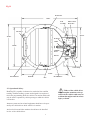
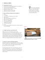
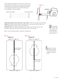
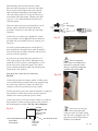
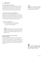
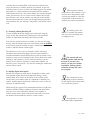
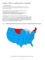
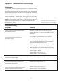
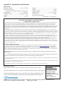
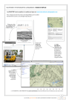
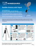
INSTALLATION/OPERATION MANUAL
SATELLITE SYSTEM
MODEL LP-1000
Made in U.S.A.
U.S. Patent Pending
Winegard Company • 3000 Kirkwood St. • Burlington, IA 52601-2000 • 319/754-0600 • FAX 319/754-0787 • www.winegard.com
Printed in U.S.A. © Winegard Company 2004, 2005
2452040
Rev. 12/19/05
1
Congratulations!
You have selected one of the most advanced and lowest profile satellite antennas available today. The Winegard
RoadTrip™ LP antenna is a technologically advanced satellite tracking system. The RoadTrip LP is designed for use
with DIRECTV® and DISH Network® satellite television providers. This manual provides important information
on the installation and operation of your RoadTrip LP antenna. Please take time to read the manual before installing
or operating your antenna.
Icons appearing in the manual are used for important information and helpful tips.
Alert indicates important information regarding
product use, product specifications or procedures.
Important tip offers helpful suggestions or
refers you to a related topic in the manual.
RoadTrip LP Model Number
LP-1000 is a satellite antenna unit designed for open road tracking and stationary use.
It is equipped with a single LNB for use with one satellite receiver.
Place RoadTrip LP serial number here
The serial number provided above, also located on the antenna under the
radome, will be required for all troubleshooting or service calls.
Disclaimer
Although every effort has been made to insure the
information in this manual is correct and complete, no
company shall be held liable for any errors or
omissions in this manual. All information contained in
this manual is subject to change without notice. No
warranty of any kind is made with regard to the
information included in this manual. The RoadTrip LP
antenna is designed specifically for use with
motorized recreational vehicles and information
contained herein is provided for that purpose only.
Trademarks
Winegard and RoadTrip are trademarks of Winegard
Company. DISH Network is a registered trademark of
EchoStar Communications Corp. DIRECTV is a
registered trademark of Hughes Electronics Corp. All
trademarks contained in this manual are property of their
respective owners. Reference made to products or
services provided by companies, other than Winegard
Company, does not represent any endorsement of those
products or services.
2
1. Introduction ........................................................................................................................... 4
1.1 System Overview ............................................................................................................ 4
1.2 Parts Provided with RoadTrip LP .................................................................................. 4
1.3 Additional Equipment and Materials Required for Operation of RoadTrip LP ............ 4
2. Safety .................................................................................................................................... 4
2.1 Installation Safety ........................................................................................................... 4
2.2 Operational Safety .......................................................................................................... 5
3. Installation ........................................................................................................................... 6
3.1 Installation Overview ..................................................................................................... 6
3.2 Tools and Material Required for Installation ................................................................. 6
3.3 Unpack and Inspect Your Unit ....................................................................................... 6
3.4 Select a Location to Mount the Antenna ..................................................................... 6-7
3.5 Mounting the Antenna .................................................................................................... 8
3.6 Adjusting Antenna Switch Settings ................................................................................ 9
3.7 Install and Connect Cables and Wiring ................................................................... 10-11
4. Operation ............................................................................................................................ 12
4.1 Initial Satellite Receiver Setup ..................................................................................... 12
4.2 Stationary Operation of RoadTrip LP .......................................................................... 12
4.3 Tracking with RoadTrip LP .......................................................................................... 13
4.4 Satellite Signal Interruption ......................................................................................... 13
Appendix A
Satellite Coverage Maps and Receiver Compatability
A.1 DISH Network ........................................................................................................... 14
A.2 DIRECTV .................................................................................................................. 15
Appendix B
Setup and Operation of Satellite Receivers
B.1 DISH Network ...................................................................................................... 16-17
B.2 DIRECTV .................................................................................................................. 18
Appendix C Maintenance and Troubleshooting ..................................................................... 19
Appendix D Specifications and Warranty ............................................................................... 20
3
1. INTRODUCTION
1.1 System Overview
The Winegard RoadTrip LP is a low profile, in-motion satellite system.
RoadTrip LP utilizes GPS (global positioning system) and DVB (digital
video broadcasting) technology. GPS is used to determine the present
location of your antenna, and DVB is used to verify the antenna has
located the correct satellite.
Roadtrip is a Ku-band satellite television reception antenna that
is gyro stabilized and has a continuous 360° rotation to keep it
locked on the selected satellite. RoadTrip is designed for both
open-road tracking and stationary operation.
The RoadTrip system has certain operational limits with
respect to use in the United States. Although designed for use with
DISH Network and DIRECTV, the system may not work in all
geographical locations or with all satellite receivers. See coverage
maps, pages 14 and 15.
Please refer to
appendix A for satellite
coverage maps and information on receiver
compatability.
1.2 Parts Provided with RoadTrip LP
1. Antenna System (includes antenna, LNB, baseplate and control electronics) Fig 1.1
2. Radome
3. Mounting Bracket (4)
4. 35 ft. RG-6 coax with weather-protected male F-connector
5. 35 ft 2-conduct 16 AWG power wire with weather-protected connector
6. Hardware Kit (See Section 3.5 for contents)
7. Installation/Operation Manual
See page five for diagram of interior and parts
1.3 Additional Equipment and Materials Required for Operation of
RoadTrip LP
1. Television or Video Monitor
2. Satellite Receiver with authorized programming
3. Approved sealant for roof
2. SAFETY
2.1 Installation Safety:
Winegard highly recommends the RoadTrip LP antenna system be
installed by a professional installer who is familiar with satellite antenna
technology and recreational vehicle wiring.
Do not attempt to install this system in the rain. Sensitive electronics
may be exposed and water may also enter vehicle. Before drilling any holes for
installation, make sure thre are no obstructions, such as wiring, etc.
Read the entire manual before attempting to install the antenna
system. Follow the instructions carefully when you begin.
Use all appropriate safety equipment, including eye protection, when
installing this system.
4
Do not attempt to
install the antenna system
by yourself. Two or more
people are required to lift
the antenna onto the roof.
Winegard is not
liable for damage,
expenses, or injury caused
by improper installation.
Fig 1.1
Rotate Base
40.00”
PCB
Assembly
Main Control
Electronics
Sub-base
28.625”
33.500”
EL Motor
LNBF
28.625”
Azimuth
Motor
Pill Box
GPS
Cable Clamp
33.250”
Knee Reflector
Reflector
Base
2.2 Operational Safety:
RoadTrip LP is capable of advanced on-road television satellite
tracking. Satellite tracking systems are designed for reception of
television programming while the vehicle is in motion and should
only be used or operated by vehicle passengers while the vehicle
is in motion.
Antenna systems and associated equipment should never be operated by the vehicle driver while vehicle is in motion.
Active television and video monitors should never be installed
in view of the vehicle driver.
5
Back Reflector
Foot
Failure of the vehicle driver
to pay complete attention to the operation of the vehicle could cause an
accident that might result in serious
injury or death.
3. INSTALLATION
3.1
1.
2.
3.
4.
5.
6.
Installation Overview:
Gather the tools and materials required for installation
Unpack and inspect RoadTrip LP
Select a location to mount the antenna.
Mount the antenna system
Adjust the antenna switch settings
Route and connect coax and wires.
Plan your entire installation
before you start. Determine the
location of all of your equipment and make sure cable and
wires are long enough to reach
their termination points.
.
3.2 Tools and Material Required for Installation:
1. Drill
2. ½” drill bit
3. 1¼” hole saw (if mounting switch in wall)
2. Tape measure
3. Wire cutter/stripper for 16 AWG wire
4. RG-6 connector crimp tool
5. RG-6 coax stripping tool
6. 7/16” open-end wrenches
7. Phillips #2 Screwdriver
8. 1/2” open-end wrench
9. Level
10. Sealant (check with RV manufacturer for proper type for
your roof material)
3.3 Unpack and Inspect the RoadTrip LP
When you receive your antenna, inspect for any
damage that may have occurred during shipping. To safely
remove the unit from the box, use two people. Open box
and carefully remove the unit. The unit will be shipped with
radome attached to protect the unit. RoadTrip LP will also be
shipped with the mounting brackets preattached to the base.
There are no shipping restraints on the antenna to remove.
3.4 Select a Location to Mount the Antenna
Select level location on your roof that has a clear view of the
horizon in all directions. Although the unit can be mounted up
to +/- 3 degrees off level, for fastest acquisition mount
the unit as close to level as possible.
The unit should be kept clear of all obstructions on the roof
(air conditioning units, etc.). If you have an obstruction on
the roof that may interfere with reception, use the following
guidelines for determining the distance from obstruction to
mount antenna.
6
Fig 3.1
If using a knife to open carton, be careful
not to damage the radome or cables.
If the height of the obstruction on the roof is 6 inches, the
antenna should be mounted no closer than 18 inches from
the obstruction. If the obstruction is higher than 6 inches,
you should add an additional 10 inches in distance for
every additional 3 inches in height.
Obstruction Height
Clearance distance
6"……………………………………….18"
9"……………………………………….28"
12"……………………………………….38"
15"……………………………………….48"
UNIT BASE
OBSTRUC
TION
Fig 3.2
.
Mount the antenna on the center line of the vehicle. There are two options for mounting.
Option A: Point the antenna directly toward the front of the vehicle with the cables and
wiring exiting the rear, driver’s side, of the antenna.
Option B: Mount the antenna pointing directly towards the back of the vehicle with
the cables and wiring exiting the front, passenger’s side, of the antenna.
Refer to the following drawings of Option A and Option B.
Fig 3.3
The mounting
option will be one
of the factors used
to determine the
correct switch setting in Section 3.6
Fig 3.3.1
Option A
Option B
FRONT OF VEHICLE
FRONT OF VEHICLE
Failure to mount
the antenna correctly
may result in inferior
tracking or failure to
track.
Mount on center
line of vehicle.
Mount on center
line of vehicle.
BACK OF VEHICLE
BACK OF VEHICLE
7
Rev. 9/30/05
3.5 Mounting the Antenna
Hardware Kit:
1. Cable ties ..............................................................2
2. Rocker switch .......................................................1
3. Surface mount box screw, #6 x 1/2 ......................2
4. Wallplate, surface mount screw #6-32x1, white ..2
5. Surface mount screw, #6 x 3/4, white ..................2
6. RG-6 connector O-ring/gel ..................................2
7. Small red flag connector ......................................2
8. Large red flag connector ......................................1
9. Cable clamps ........................................................2
10. Surface mount box ...............................................1
11. Cable entry plate ..................................................1
12. Wallplate, white ...................................................1
13. Packaged screws ............................................... 30
14. Protective radome wipe........................................1
1.
11.
10.
14.
3.
13.
5.
4.
12.
6.
7.
Hardware Kit Contents
Level the vehicle before mounting antenna.
Clean the roof area that was selected in Section 3.4. Move the
antenna unit to the roof and place in permanent location.
8.
9.
2.
When moving the antenna,
always leave radome on to avoid
damaging the antenna. Never
handle the antenna unit by the
cable or wiring.
Fig 3.4
Locknut
Using a level, adjust the leveling screws by
tightening or loosening the flange nut under the
baseplate mounting foot, Fig 3.4.
Baseplate
Flange Nut
Remove locknut from foot, Fig. 3.4. Lift up baseplate,
slide foot out and apply sealant to bottom of foot.
Slide back into place and tighten locknut.
Foot
Screw down brackets attached to antenna using (4) # 10 screws for
each bracket. After all mounting brackets are secured, add sealant
on top of bracket and screws.
.
Be careful not get any
sealant on cable or wire
connectors.
8
Rev. 12/05
3.6 Adjusting the Antenna Switch Settings
Depending on the satellite receiver and the mounting option
selected, it may be necessary to remove the antenna radome
and adjust the switch setting. The antenna switch comes preset at the
factory for mounting Option A (see Section 3.4 Fig 3.3) and for use with
DirecTV receivers (see Fig 3.5). If you have selected mounting
Option B, or if you are using a DISH network receiver, remove the antenna radome
and adjust the switch setting on top of the main control board (see Fig 3.6).
Fig 3.5
Switches set for DirecTV
mount Option A.
To adjust your antenna switch setting, remove the screws (16) that
attach the radome to the base. Carefully remove the radome and
set it down beside the unit. Find the Antenna Switch located on
top of the main control board and adjust the switch to the
appropriate setting for the mounting option and satellite receiver
(See Fig 3.6).
Antenna switches may
need to be adjusted prior to
operating the system.
Some Coach manufacturers may have changed these
settings during installation.
Verify mounting option and
receiver setting as shown.
Refer to Section 1,
Fig. 1.1, for Main Control
Board location.
The position switches are numbered 1 through 8, left to right.
Each switch position has a value of 1 or 0.
To select the 1 value, flip the switch to the down position.
To select the 0 value, flip the switch to the up position.
Example
Switches set for DISH Network,
mount option A.
Fig 3.6
Sat. Rcvr.
Mount Option
1
2
Switch Set Position
3 4 5 6 7 8
DISH NETWORK ................. A...................... 0 ... 0 ..... 0 .... 1 .... 0 .. 0 .. 1 .. 1
DISH NETWORK ................. B...................... 1 .... 0 .... 0 .... 1 .... 0 .. 0 ... 1 .. 1
DIRECTV ............................. A...................... 0 .... 0 ..... 0 .... 0 .... 0 .. 0 ... 0 .. 1 (FACTORY PRESET)
DIRECTV ............................. B...................... 1 .... 0 ..... 0 .... 0 .... 0 .. 0 ... 0 .. 1
The antenna switch setting is very important for proper installation
for your antenna. If the unit does not find the correct satellite while
stationary, make sure you have the switch set for the correct satellite
television provider. If the unit is operational while the vehicle is
stationary, but does not track properly when in motion, make sure you
have selected the appropriate switch setting for satellite television
provider and proper mounting option.
9
Rev. 9/30/05
3.7 Route and connect the coax and wires
Determine the best location for the RG-6 coax and 16 gauge
power wires to enter the vehicle, and the location of the satellite
receiver and rocker switch. Drill ½“ hole in the roof for the coax
and power wires to enter the vehicle. Insert the ends of the 35’
section of RG-6 and 35’ section of 16 gauge power wire into the
hole. Be sure to insert the ends that do not have connectors on
them. Push coax and power wires into the vehicle.
Using a 7/16" wrench, attach the weather-protected F-connector to the feed-through coming from the dome. First,
hand-tighten the connector onto the feed-through until it seats
into the rubber seal. Using one 7/16" wrench to hold the center
of the feed-through, lightly tighten the F-connector to the
feed-through using the other 7/16" wrench. Repeat the above
step to attach F-connector on the 35’ cable to feed-through.
All coax connections
must be finger tightened, then
given 1/4” turn with a 7/16”
wrench.
Fig 3.7
Attach the weather-protected power connector from the
antenna to the weather-protected power connector on the
35’section of wire. The power connector is directional. Align
wire colors and firmly push connector together until latch
snaps and secures.
Fig 3.8
10
Rev. 9/30/05
Pull remaining cable and wire into the vehicle.
Place the cable entry plate over the hole and cables.
Screw in place and seal plate and screws with the
approved sealant. Depending on the length of the
coax and wiring on the roof, it may be necessary to
secure them with cable clamps. Clamping the cable
every 12" to 16" should eliminate any unecessary
cable movement.
Trim coax cable if necessary and strip RG-6 coax inside the vehicle, illustration at right. Attach the
provided F-connector to end of the coax and crimp
connector.
Connect the coax cable to the “Satellite In” connection on satellite receiver, Fig 3.9. Follow instructions
provided with your satellite receiver to connect your
television.
Fig 3.9
Use wall or panel mounted power switch; drill 1¼”
hole and pull wires through wall or panel. If using the
surface mount box provided, mount box and feed wire
into one of the box openings.
It is necessary to connect the power switch to a 12
VDC power source in the vehicle. Winegard recommends the 12 VDC source be wired directly to a 12 V
fused source in the vehicle fuse panel. The vehicle
power connection should be made last with the power
switch in the “Off ”position.
Do not connect the
power wires to an unknown or
unfused 12 volt power source.
Doing so could cause improper
operation and a fire hazard.
Snap the power switch into the switch plate,
Fig 3.10.
Fig 3.10
Connect the ground wire from the vehicle 12 VDC power
source and the antenna ground (black) wire together using
the yellow flag connector. Connect the yellow flag
connector to the silver spade on the power switch.
Connect the positive (red) wire from the antenna to a small red
flag connector. Connect the red flag connector from the
antenna to the center spade on the power switch.
Connect the positive 12V wire from the vehicle to a small red
flag connector. Connect red flag connector from vehicle to
the isolated spade on switch. (See Fig 3.11 for diagram)
Fig 3.11
Two( black) GROUND wires
1 from vehicle
1 from antenna
ON/OFF
ROCKER WITH
LIGHT
(Shown in OFF
position.)
+12 VDC from vehicle
Power wire
(red) from
antenna
11
If necessary you may disconnect the weather-protected
connector on the roof while wiring
unit. The unit is equipped with a 7.5
amp fuse located on the bottom of
the Main Control Board.
Rev. 12/05
4. OPERATION
4.1 Initial Satellite Receiver Setup
It is very important to set up the satellite receiver for proper
antenna operation. Receiver hardware and software varies,
depending on manufacturer. If you have a new receiver or
you have removed your satellite receiver from the vehicle,
it may be necessary to repeat the satellite receiver setup.
Refer to Appendix B for satellite
receiver setups for initial and multidish
operation. Follow the instructions for
your satellite television provider.
4.2 Stationary Operation of the RoadTrip LP
After antenna has been installed and satellite receiver
properly set up, operation of RoadTrip LP is easy and entirely
automatic. Winegard recommends when parking your vehicle,
the antenna has a clear view of the southern sky. The antenna
only needs to see the required satellite(s); however, a clear view
of the southern sky should improve satellite acquisition.
To Operate the RoadTrip LP:
1. Power on satellite receiver and television.
2. Power the antenna using the power switch
and wait for satellite acquisition.
On intial setups, it may be necessary to set up your
receiver for multidish operation (if required) after the unit
has acquired the satellite and entered sleep mode. Refer to
Appendix B for information on multidish setups for your
satellite provider.
How the RoadTrip Works During Stationary
Satellite Acquisition:
The reflector on the antenna will rotate clockwise until the reflector is positioned directly over the front of the vehicle.
The antenna reflector will then move to the maximum elevation
to set the noise baseline for the RF detector. This is the home
position for the antenna. After it is in the home position and the
baseline is determined, the antenna will wait to acquire GPS
information.
It is normal for your television to
display the message, “Satellite Signal
Lost Searching for Signal” while the
antenna is acquiring the satellite.
12
Rev. 9/30/05
After the unit has acquired GPS, it will lower the reflector to the
proper elevation for a satellite search in your location. As the unit
scans the proper elevation, it will locate satellite signals. The antenna
will return to a scanned satellite location and verify the satellite’s
DVB identification. If it is the correct satellite, the antenna will peak
on the signal and stop. If it is not the correct satellite, the unit will
move directly to the correct satellite, stop and peak on the satellite.
The unit will continue the conical scan for approximately 6 minutes.
After 6 minutes, the unit will enter “sleep mode” and end the conical
scan.
4.3 Tracking with the RoadTrip LP
To track with the RoadTrip, simply power on the unit using the
power switch. The antenna will go through the same acquisition
routines as it did while searching in the stationary mode.
GPS acquisition will normally take less than a minute. If you
have traveled a long distance without using the antenna or if the dish
is being used for the first time, acquisition may take several minutes.
If searching for the 101
DIRECTV satellite, the antenna
will verify the 110 satellite prior
to stopping on 101.
If the unit was already locked on a satellite, you only need to begin
moving. After the antenna unit senses forward movement at 10 MPH,
it will actively track the satellite or begin a satellite tracking search
routine to find the desired satellite signal.
The antenna uses active gyros to determine vehicle movement
and adjusts the antenna accordingly. Once the desired satellite is
located and identified, the RoadTrip will stay actively locked on the
satellite by using a conical tracking routine. If the vehicle stops while
tracking, it will continue to actively track the satellite for up to 6
minutes. If the vehicle is stationary for more than 6 minutes, the
unit will go into “sleep mode”, stop actively tracking the satellite and
end the conical search.
4.4 Satellite Signal Interruption
Satellite TV reception systems may be disrupted by weather conditions. Satellite signals may be lost temporarily during a steady
rainfall. Rain, snow or dew on the surface of the radome can adversely affect your satellite signal. It is important to maintain your
radome with the approved protectant, and remove water or snow by
wiping it off when necessary.
The antenna will only
track the satellite while moving
forward. If you back your
vehicle, you may lose satellite
acquisition. Turning quickly
when first moving may cause
loss of signal.
The antenna has an automatic peaking routine to maintain
the best signal while in sleep mode
or in a stationary position.
While moving, the signal can be interrupted when line-of-sight to the
satellite is blocked. Tunnels, highway overpasses and dense urban
areas are a few of the obstructions that may cause signal loss
while in motion. If the signal is blocked for more than 15 seconds,
the antenna will automatically return to a search routine.
See Appendix C for periodic maintainance requirements.
13
Rev. 9/30/05
Appendix A Satellite Coverage Maps and Receiver Compatability
A.1 DISH NETWORK
The RoadTrip LP will operate with most standard DISH Network receivers.
The antenna will continually track satellite 119 and will function while stationary
with satellites 119 and 110.
The RoadTrip LP will not operate with DISH Network HDTV receivers or
with any DISH Network satellites other than 119.
Winegard does not recommend using receivers with hard drives not
recommended by the manufactuer for mobile applications.
The RoadTrip will not operate in areas where satellite 119 is not avaliable.
Refer to Fig A.1.1 for an operational coverage map for satellite 119. Satellite coverage
maps are based on level, stationary operation. When tracking with the RoadTrip, road
grades, hills, on and off ramps and other inclines, may effect the operation when
slope is severe, or when approaching fringe areas of operation. Reception interruption may also occur during adverse weather conditions.
Fig A.1.1 DISH Network satellites 119 and 110 coverage area (Area shaded in blue indicates coverage).*
*Coverage maps are for reference only and do not guarantee coverage.
14
14
A.2 DIRECTV
RoadTrip LP will operate with most standard DIRECTV receivers. The antenna will continually track satellite 101 and
will function while stationary with satellites 101 and 119.
RoadTrip LP will not operate with DIRECTV HDTV receivers or on any other DIRECTV satellites other than 101 and
119. Winegard does not recommend using satellite receivers with hard drives not recommended by the manufacturer for mobile applications.
RoadTrip will not operate in all areas satellites 101 and 119 are available. Refer to Fig A.2.1 for an operational coverage map of satellite 101 and to Fig A.2.2 for an operational coverage map of 119. Satellite coverage maps are based on
level, stationary operation. When tracking with the RoadTrip antenna, road grades, hills, on and off ramps and
other inclines may effect the operation when slope is severe, or when approaching fringe areas of operation. Reception interruption may also occur during adverse weather conditions.
Fig A.2.1 DIRECTV satellite 101 RoadTrip coverage map (Area shaded in blue indicates coverage).*
Fig A.2.2 DIRECTV satellite 119 RoadTrip coverage map (Area shaded in blue indicates coverage).*
*Coverage maps are for reference only and do not guarantee coverage.
15
Appendix B Setup and Operation of Satellite Receivers
B.1 DISH Network (To activate your DISH Network receiver, call 1-888-ADD-DISH).
Using your DISH Network Point Dish/Signal Screen
There are several applications where it is necessary and helpful to use the DISH Network
Point Dish/Signal Screen. See Fig B.1.1. The following instructions will help you
acquire this screen on most DISH Network receivers. You will use this screen
to determine if you are locked on the correct satellite, and for Check Switch setups.
Press the “Menu” button on the remote control.
Select “System Setup” option “6”.
Select “Installation” option “1”.
Select “Point Dish/Signal” option “1”.
If you do not see a signal on your meter, be sure satellite 119 is
selected and try a different transponder. All transponders may not be active.
Fig B.1.1
DISH Network Point Dish/Signal Screen
Downloading New DISH Network Receivers
If you own or use an activated receiver that has been previously downloaded,
you will not have to download the receiver.
New DISH Network receivers require downloading and program activation.
To download your receiver, follow the instructions included with your
specific receiver. If you do not have a manual for your receiver, contact
DISH Network or visit their website at www.echostar.com. Winegard suggests
downloading a new receiver on a fixed dish (such as a residential dish) whenever
possible. If this not possible, you may download on the RoadTrip antenna. Connect
the new receiver to the RoadTrip and turn on the system. In your “Point Dish/Signal”
screen, check the box next to 119 and wait for the system to acquire the satellite. After
the system has acquired the satellite and stopped the conical search, turn off the antenna.
Be sure the signal strength meter indicates a strong signal on satellite 119, then continue
following download instructions.
16
Using your DISH Network Receiver for Multidish Operation
To set your receiver to automatically switch from satellite 119 to
satellite 110 in stationary mode, use the following instructions:
In stationary position, be sure you have a clear view of satellites
119 and 110.
Go to “Point Dish/Signal” screen and select the 119 satellite.
Turn on the RoadTrip antenna to begin search for the
desired satellite.
Wait for RoadTrip to search and acquire satellite 119, end the conical
search and enter “Sleep” mode (this will take approximately 6
minutes after 119 is found).
Using the arrow buttons on your remote, highlight the “Check Switch”
box. Select “Check Switch”, then select “Test”.
The “Check Switch” will take a few minutes to complete. When complete,
Installation Summary screen should show an Installed Switch of SW42
and should display information for 119 and 110, including odd and even
transponders. See Fig B.1.2.
Make sure all options
are unchecked on checkswitch
screen. (i.e “Superdish” should
not be checked).
Fig B.1.2
DISH Network Installation Summary Screen
If the screen does not show the correct switch, repeat procedure until
it is correct. After the SW42 switch is installed, you do not need to
repeat this procedure unless the “Check Switch” is changed to a
switch other than SW42.
You may receive an Error Message when the dish is
automatically moving between satellites as you change
channels. If you are prompted to run “Check Switch”, ignore
this message if the switch is already set up to SW42 with 119
and 110 odd and even transponder information.
17
Rev. 9/30/05
B.2 DIRECTV (To activate your DIRECTV receiver, call 1-888-238-7177)
There are many manufacturers of DIRECTV Receivers. These instructions are for use with common menus found
in most DIRECTV Receivers. If they differ from your receiver, follow instructions provided with your receiver.
Set up your DIRECTV Receiver Dish
Select “Menu” on the remote control to access Main Menu.
Select ‘7’ for “Dish Pointing” and press OK.
Use arrow buttons and highlight “Select Dish” and
press “OK”.
Specify the oval dish two satellite option by selecting in the “Select Dish Antenna” screen, (Fig B.2.1). If you
have an older DIRECTV receiver that does not have this option, skip this step.
Fig B.2.1
Back
Help
Select Satellite Dish Antenna
Select Dish
Enter ZIP Code
Select Dish
Select by City
Enter Lat/Long
Signal Meter
Select Dish
Next
Using the Oval Satellite Dish allows you to receive primary DIRECTV
programming and local programming if available.
Select Dish Antenna Screen, (RCA Receiver Shown)
Using the DIRECTV Dish Pointing Screen
The DIRECTV Dish Pointing Screen (Fig B.2.2) can be useful in determining satellite position and acquisition. The
following instructions will help you access the “Dish Pointing Screen” on most DIRECTV receivers.
Fig B.2.2
Select “Menu” on your remote control to access the “Main Menu”.
Select ‘7’ for Dish Pointing, then press “OK”.
Use the arrow buttons to highlight
“Signal Meter” and press “OK”.
Select satellite “101”.
If you do not receive a signal on your meter,
try another transponder. All transponders may not
be active.
Downloading New DIRECTV Receivers (If your
receiver has been previously downloaded, you
do not have to follow this procedure.)
Back
Help
Select Dish
Enter ZIP Code
Select by City
Enter Lat/Long
Signal Meter
Signal Meter
101W Sat
Transponder + Current:
Peak
110/119W Sat
Transponder
Current:
Peak
Alternate for fine tuning
The signal strength meter indicates the strength of the satellite signal.
Press OK to continue.
DIRECTV Dish Pointing Screen, (RCA Receiver Shown)
Some new DIRECTV Receivers may require downloading prior to use. If you need to download your receiver,
Winegard recommends downloading your receiver on a fixed dish (such as a residential dish) when possible. If
you cannot download your receiver on a fixed dish, connect the receiver to RoadTrip. In the “Dish Pointing”
screen select “Satellite 101. Turn on antenna and wait for satellite 101 to be acquired. After satellite has been
acquired, wait for the unit to stop the conical search and enter “Sleep” mode. Turn off the antenna. Be sure you
have a signal on your signal meter. Follow the instructions provided with your receiver to complete the download.
Using your DirecTV Receiver for MultiDish Operation
If the DIRECTV receiver is capable of MultiDish operation, there are no additional procedures to follow. The receiver will toggle between satellites automatically as long as the dish type has been properly configured to oval.
18
Rev. 9/30/05
Appendix C. Maintenance and Troubleshooting
Maintenance
It is advisable to perform monthly maintenance on your antenna. Clean
off bugs and dirt on the outside of radome using mild soap and water;
treat radome with ProtectAll*. Check fasteners on radome, antenna and
antenna mounting brackets and tighten if necessary. Be sure cables and
wiring are properly connected and secured.
Annual maintenance — remove radome from antenna and clean off dirt
and debris from antenna base using a clean rag. Do not use cleaners or
liquids to clean the inside of the antenna; electronics may be damaged.
Before replacing the radome, be sure all drain holes in the base are
clear and free of debris.
*ProtectAll is distributed by Protect All, Inc.,
Anaheim, CA 92806-1215; www.protectall.com
Troubleshooting
Symptom
Remedy
Turn on power switch and nothing happens.
Antenna does not move.
Check for 12 VDC power at power plug on roof.
Remove and check 7.5 amp fuse under Main Control
Electronics.
Unit searches but does not lock onto
any satellite signal.
Be sure there is an unobstructed view of desired
satellite(s).
Check for 12 VDC to 18 VDC voltage on coax cable
on roof connected to Satellite In receiver connection.
Check all coax cable and connections.
Tighten coax connectors with wrench, Section 3.7.
Be sure DirecTV receiver is set to oval dish.
Make sure DISH receiver Check Switch has the information for desired satellite — or is set to No Switch
detected (factory default).
Check switch settings, Section 3.6.
Remove water or snow from radome.
Unit locks on wrong satellite.
Check switch settings, Section 3.6.
Unit works when stationary, but does not
track satellite when moving.
Check switch settings, Section 3.6.
Unit is receiving low satellite signal strength
that causes picture to digitize or freeze.
Check coverage maps. Pages 14-15.
Remove water or snow from radome.
19
Appendix D. Specifications and Warranty
Specifications
Frequency Band ........................... 12.2 to 12.7 GHz
Elevation Scan Range
...... 17 degrees to 63 degrees relative to the horizon
Azimuth Scan .......................................... Continous
Tracking Velocity ....................... 45 degrees/second
Length ................................................................. 40”
Width ............................................................ 33-1/2”
Height ....................................................................6”
Weight ............................................................. 62 lbs
Shipping Weight ............................................. 78 lbs
Supply Voltage............................. 11.5 to 14.5 VDC
Peak Current ................................................. 5 Amps
Operational Temperature
................................ –25 degrees C to 70 degrees C
WINEGARD MOBILE PRODUCTS LIMITED WARRANTY
(2 YEARS PARTS; 1 YEAR LABOR)
Winegard Company warrants this product against defects in materials or workmanship for a period of two (2) years from the date of original purchase.
During year one (1) of such warranty, Winegard Company will also pay authorized labor costs to an authorized Winegard dealer to repair or replace
defective products. No warranty claim will be honored unless at the time the claim is made, Customer presents proof of purchase to an authorized
Winegard dealer (to locate the nearest authorized Winegard dealer, contact Winegard Company, 3000 Kirkwood Street, Burlington, Iowa 52601, Telephone
319-754-0600 or visit www.winegard.com). Customer must provide proof of purchase with a dated sales receipt for the Winegard product to verify the
product is under warranty. If the date of purchase cannot be verified, the warranty period shall be considered to begin thirty (30) days after the date of
manufacture.
If a defect in material or workmanship is discovered, Customer may take the product to an authorized Winegard dealer for service. Customer must
provide proof of purchase to verify the product is under warranty. If the product is brought to an authorized Winegard dealer for service prior to expiration
of year one (1) of the warranty period and a defect in material or workmanship is verified by Winegard Technical Services, Winegard Company will cover
the Winegard dealer’s labor charges for warranty service. The Winegard dealer must contact Winegard Technical Services in advance for pre-approval of
the service. Approval of the service is at the sole discretion of Winegard Company.
Alternatively, Customer may ship the product prepaid to Winegard Technical Services (located at 3000 Kirkwood Street, Burlington, Iowa 52601,
Telephone 319-754-0600). Customer must return the product along with a brief description of the problem and provide Winegard Technical Services with
Customer’s name, address, and phone number. Customer must also provide proof of purchase to verify the product is under warranty. If the product is
returned before the expiration of the warranty period, Winegard Company will (at its option) either repair or replace the product.
This Limited Warranty does not apply if the product has been damaged, deteriorates, malfunctions or fails from: improper installation, misuse, abuse,
neglect, accident, tampering, modification of the product as originally manufactured by Winegard in any manner whatsoever, removing or defacing any
serial number, usage not in accordance with product instructions or acts of nature such as damage caused by wind, lightning, ice or corrosive environments
such as salt spray and acid rain.
RETURN AUTHORIZATION POLICY
A Return Material Authorization (RMA) is required prior to returning any product to Winegard Company or Winegard Warranty Services under this
warranty policy. Please call our Technical Services Department at (800) 788-4417 or send an e-mail to [email protected] to obtain the RMA
number. Please furnish the date of purchase when requesting an RMA number. Enclose the product in a prepaid package and write the RMA number in
large, clear letters on the outside of the package. To avoid confusion or misunderstanding, a shipment(s) without an RMA number(s) or an unauthorized
return(s) will be refused and returned to Customer freight collect.
WINEGARD COMPANY DOES NOT ASSUME ANY LIABILITIES FOR ANY OTHER WARRANTIES, EXPRESS OR IMPLIED, MADE BY ANY
OTHER PERSON.
ALL OTHER WARRANTIES WHETHER EXPRESS, IMPLIED OR STATUTORY INCLUDING WARRANTIES OF FITNESS FOR A PARTICULAR
PURPOSE AND MERCHANTABILITY ARE LIMITED TO THE TWO YEAR PERIOD OF THIS WARRANTY.
In states that do not allow limitations on implied warranties, or the exclusion of limitation of incidental or consequential damages, the above limitations
or exclusions do not apply.
Some states do not allow limitations on how long an implied warranty lasts, or the exclusion of limitation of incidental or consequential damages, so the
above limitations or exclusions may not apply to you.
This warranty gives Customer specific legal rights. Customer may also have other rights that may vary from state to state.
Warranty Procedure
Please contact your local dealer or installer if you have a problem with your unit.
For Winegard
warranty information:
Any parts or products that are to be returned to Winegard Company must have prior approval.
Att: Technical Services
Winegard Company
3000 Kirkwood St.
Burlington, IA 52601-2000
800-788-4417
Fax: 1-319-754-0787
Contact Winegard Technical Services at 1-800-788-4417 for a Return Authorization. Be sure
to have your unit serial number available when contacting Winegard Technical Services.
Winegard Company • 3000 Kirkwood St. • Burlington, IA 52601-2000 • 319/754-0600 • FAX 319/754-0787 • www.winegard.com
Printed in U.S.A. © Winegard Company 2004, 2005
2452040
Rev. 12/19/05
20