1
98648-004-03
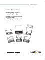
Sartorius Master Series
Electronic Weighing Instruments
Accuracy Class k or K
Analytical and Precision Balances
Installation and Operating Instructions
for Standard Models
and EC-Approved Models Acceptable
for Legal Metrological Verification
Contents
Page
Page
General Views of the Balances 1– 1
Warranty
1– 6
Storage and Shipping Condtions 1– 6
Balance Operating Menu
2– 1
Changing a Menu Code Setting 2– 2
Undoing All Menu Code
Changes: Reset Function
2– 4
Installation Instructions
1– 7
Getting Started
1– 9
Connecting the Balance
to AC Power
1–10
Voltage Selection
1–11
Connecting Electronic Devices
(Peripherals)
1–11
Safety Precautions
1–11
Information on Radio Frequency
Interference
1–12
Adjusting the Display Unit
1–12
Information on Weighing Electrostatically Charged Samples
1–12
Leveling the Balance Using
the Level Indicator
1–13
Operating the Balance
Warmup Time
Turning the Display On and Off
Self-Test
Taring
Weighing
Weighing Range Structure
1–14
1–14
1–14
1–14
1–16
1–16
1–17
Weighing in the IQ-Mode
(Load-Dependent Readability)
1–18
Calibration
Sensitivity Test
1–19
1–23
Data Interface
Below-Balance Weighing
Fastening an
Antitheft Locking Device
Troubleshooting Guide
Care and Maintenance
Manufacturer’s Declaration
1–25
1–27
1–27
1–28
1–30
1–32
Balance Operating Parameters
Adapting the Balance
to Ambient Conditions
Standard Weighing Mode –
Manual Filling Mode
Stability Range
Stability Symbol Delay
Tare Parameter
Auto Zero Function
Weighing in Three Ranges
on Standard Balances
Selecting the Number
of Ranges
Weight Units
Weighing in Two Ranges
on Verified Balances
Selecting the Number
of Ranges
Weight Units
2– 5
2– 5
2–
2–
2–
2–
2–
5
5
6
6
6
2– 7
2– 7
2– 7
2– 9
2– 9
2– 9
Display Modes on
Standard Balances
Final Readout Mode
Last Numeral Blanked When
the Load Changes
Round-Off Function
IQ-Mode
PolyRange Function
2–10
2–10
2–10
2–11
Display Modes on
Verified Balances
2–12
Calibration Functions on
Standard Balances
2–13
2–10
2–10
0 –1
Page
Calibration Functions on
Verified Balances
2–14
Utilities for Printouts
or Data Transfer
2–15
Data Output Parameter
2–15
Automatic Data Output
2–15
Data Output at Defined Intervals 2–16
Automatic Taring after
Data Output
2–16
Data ID Codes
2–17
Additional Functions
2–18
Menu Access Function on
Standard Balances
2–18
Function of the Menu Access
Switch on Verified Balances
2–18
Beep Tone (Acoustic Signal)
2–18
Blocking the Keys
2–18
Universal Switch for
Remote Control
2–19
Analog Display:
Bar Graph/Marker
2–19
Power-On Mode
2–19
Automatic Shutoff (Battery Saver) 2–20
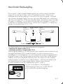
Display Backlighting
2–20
Page
“isoCAL” Self-Calibrating
Function on AC/LC…-00MS/
-0CEMS Models
3–
Range of Performance Features 3–
“isoCAL” Self-Calibrating Function 3–
Flashing W Symbol
3–
Activating Internal
Calibration Manually
3–
Automated Processes
3–
Printout or Record
of Calibration Processes
3–
Calibrating Balances when Using
YDK 01, YWP 01, YWP 01 U
or YWP 02 Accessories
3–
Calibration with the MC1-MP8
Interface (Binary Converter)
3–
1
1
2
2
3
4
4
4
4
Application Programs for Balances
of the
Product Line
4– 1
Functions Common to All Programs 4– 2
Tare Memory
Display/Print Tare –
Net – Gross Weights
Net Total
4– 4
Weighing in Percent
Determination of the Residual
Weight in Percent
Sieve Analysis
4– 6
4– 4
4– 5
4– 6
4– 7
Over/Under Checkweighing
4– 9
Checking Net Weights
4–10
Checking Variations in Weight 4–11
Counting
0 –2
4–13
Page
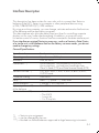
Interface Description
General Specifications
Data Output Formats
Data Input Formats
Table of ASCII Characters
5–
5–
5–
5–
5–
Synchronization and
Data Output Parameters
5–10
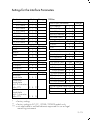
Settings for the
Interface Parameters
5–13
Control Lines
Pin Assignment Chart
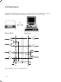
Cabling Diagram
5–14
5–15
5–16
1
1
2
6
9
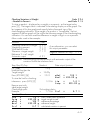
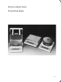
Product Data Sheets
6– 1
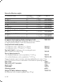
Specifications
6– 2
EC Pattern Approval Certificates 6–20
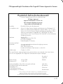
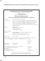
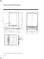
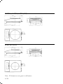
Dimensions (Scale Drawings)
6–24
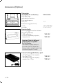
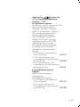
Accessories (Options)
6–28
Page
Declarations of Conformity
7– 1
The CE Mark of Conformity
on Sartorius Equipment
7– 1
“EC Verification” – A Service
Offered by Sartorius for Balances
Acceptable for Verification
7–
“New Installation” – A Service
Offered by Sartorius
7–
Subsequent Verifications within
the European Union
7–
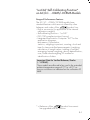
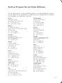
Sartorius European Service
Center Addresses
7–
4
4
4
5
Declaration of Conformity
to Directive No. 90/384/EEC 7– 6
Certification for the Sartorius
Quality System for the Weighing
Technology Division (in German) 7– 7
Declaration of Conformity
to Directive 89/336/EEC
7– 8
Supplement:
Brief Instructions
0 –3
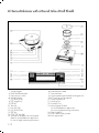
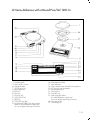
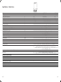
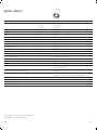
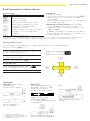
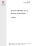
AC Series Balances with an Analytical Draft Shield Chamber
1
2
3
4
5
6
7
8
9
10
11
12
13
14
Weighing pan
Protective ring
Shield plate
Draft shield base plate
Menu access switch
Weight display
f function key
w toggle key
Info key
Tare key
Print key p
F function key
c key
ON/OFF key e
15 Verification ID label with metrological
data for verified balances approved
for use as legal measuring instruments
16 Manufacturer’s label
17 Level indicator
18 Lug for attaching an antitheft locking device
19 AC jack/power receptacle
20 Data interface port
21 Leveling foot
22 Auxiliary foot
23 Metrological ID label
for verified balances approved
for use as legal measuring instruments
1–1
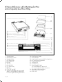
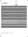
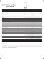
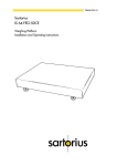
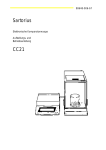
LC Series Balances with a Round Glass Draft Shield
1
4
5
6
7
8
9
10
11
12
13
14
15
Weighing pan
Draft shield base plate
Menu access switch
Weight display
f function key
w toggle key
Info key
Tare key
Print key p
F function key
c key
ON/OFF key e
Verification ID label with metrological
data for verified balances approved
for use as legal measuring instruments
1–2
16
17
18
19
20
21
22
23
Manufacturer’s label
Level indicator
Lug for attaching an antitheft locking device
AC jack/power receptacle
Data interface port
Leveling foot
Auxiliary foot
Metrological ID label
for verified balances approved
for use as legal measuring instruments
24 Draft shield lid
25 Glass draft shield cylinder
26 Pan support disk
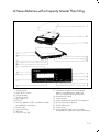
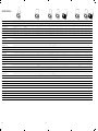
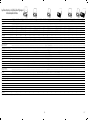
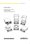
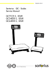
LC Series Balances with a Round Pan/GC 1201-G
1
5
6
7
8
9
10
11
12
13
14
15
Weighing pan
Menu access switch
Weight display
f function key
w toggle key
Info key
Tare key
Print key p
F function key
c key
ON/OFF key e
Verification ID label with metrological
data for verified balances approved
for use as legal measuring instruments
16
17
18
19
20
21
22
23
Manufacturer’s label
Level indicator
Lug for attaching an antitheft locking device
AC jack/power receptacle
Data interface port
Leveling foot
Auxiliary foot
Metrological ID label
for verified balances approved
for use as legal measuring instruments
26 Pan support disk
27 Centering disk
1–3
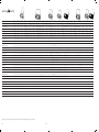
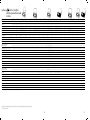
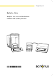
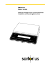
LC Series Balances with a Rectangular Pan
and a Capacity Less Than12 kg
1
5
6
7
8
9
10
11
12
13
14
15
Weighing pan
Menu access switch
Weight display
f function key
w toggle key
Info key
Tare key
Print key p
F function key
c key
ON/OFF key e
Verification ID label with metrological
data for verified balances approved
for use as legal measuring instruments
1–4
16
17
18
19
20
21
22
23
Manufacturer’s label
Level indicator
Lug for attaching an antitheft locking device
AC jack/power receptacle
Data interface port
Leveling foot
Auxiliary foot
Metrological ID label
for verified balances approved
for use as legal measuring instruments
28 Pan draft shield (metal frame,
depending on the model)
29 Dust cover
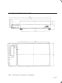
LC Series Balances with a Capacity Greater Than12 kg
1
5
6
7
8
9
10
11
12
13
14
Weighing pan
Menu access switch
Weight display
f function key
w toggle key
Info key
Tare key (labeled “TARE” on balance models
acceptable for verification)
Print key p
F function key
c key
ON/OFF key e
15 Verification ID label with metrological
data for verified balances approved
for use as legal measuring instruments
16 Manufacturer’s label
17 Level indicator
18 Lug for attaching an antitheft locking device
19 AC jack/power receptacle
20 Data interface port
21 Leveling foot
23 Metrological ID label (only for models
acceptable for legal metrological verification)
1–5
With this Sartorius balance, you have acquired
a high-quality electronic weighing instrument that will
ease your daily workload.
Please read through these installation and
operating instructions carefully before operating
your new balance.
In the first part of these installation and operating
instructions, it is assumed that you are using the factoryset menu codes.
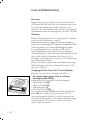
Warranty
Do not miss out on the benefits of our full warranty.
Please complete the warranty registration card,
indicating the date of installation, and return the card
to your Sartorius office or dealer.
Storage and Shipping Conditions
Allowable storage temperature:
+5 °C ... +40 °C
+41°F ...+104 °F
The packaging has been designed to ensure that
the balance will not get damaged even if it is dropped
from a height of 80 cm max. (about 32 inches).
Carefully unpack the balance and check the
equipment immediately for any visible damage
as a result of rough handling during shipment.
If this is the case, proceed as directed in the section
entitled “Safety Inspection.”
Save the box and all parts of the packaging in case
you need to ship your balance. For shipping your
balance, disconnect all cables before packing. Use
only the complete original standard packaging to
prevent damage to the equipment during shipment.
Do not expose the balance unnecessarily to extreme
temperatures, moisture, shocks, blows or vibrations.
1–6
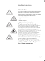
Installation Instructions
Ambient Conditions
Your Sartorius balance will provide accurate readouts
even when it is exposed to unfavorable conditions.
Please choose a suitable place to set up your balance.
It should not be exposed to the following:
– extreme heat radiation
– drafts
– extreme vibrations
– aggressive chemical atmospheres
The balance may not be used in hazardous
areas/locations where there is danger of explosion.
Do not expose the balance to extreme moisture
over long periods. Moisture in the air can condense
on the surfaces of a cold balance whenever it is
brought to a substantially warmer place. If you transfer
the balance to a warmer area, make sure to
condition it for about 2 hours at room temperature,
leaving it unplugged. Afterwards, if you keep
the balance connected to AC power, the continuous
positive difference in temperature between the
inside of the balance and the outside will practically
rule out the effects of moisture condensation.
You can adapt the balance to your requirements
simply by changing the code settings in the balance
operating menu. For more information, please see
Part 2, “Balance Operating Menu.”
1–7
Using Verified Balances as Legal Measuring
Instruments in the EU*
You must calibrate the balance at the place
of installation before using it as a legal measuring
instrument (see the section entitled “Adjustment/
Calibration” starting on page 1–19).
This balance is not allowed to be used for weighing
goods intended for direct sale to the public. The
type-approval certificate for verification applies only
to non-automatic weighing instruments; for
automatic operation with or without auxiliary
measuring devices, you must comply with the
regulations of your country applicable to the place
of installation of your balance. A suitable
thermometer and barometer are recommended for
monitoring ambient conditions.
For balances of accuracy class k, a thermometer
and barometer are recommended for monitoring
ambient conditions. The temperature range
indicated on the verification ID label must not be
exceeded during operation.
The balance must warm up for at least 24 hours
after initial connection to AC power or after
a relatively long power outage.
Sartorius complies with EC Directive No. 90/384/
EEC for non-automatic weighing instruments,
which has been in effect since January 1, 1993,
within the Single European Market, as well as
the accreditation of the Quality Management
System of Sartorius AG by Lower Saxony’s
Regional Administrative Department of Legal
Metrology (Niedersächsische Landesverwaltungsamt – Eichwesen) from February 15, 1993.
* including the signatories of the Agreement on the
European Economic Area
1–8
Getting Started
Important Note Concerning All Verified Balances
Approved for Use as Legal Measuring Instruments
in the EU
Provided that an official seal is required for
the verified balance, a control seal is affixed to
the balance. Unauthorized attempts to remove this
seal will irreversibly damage it. If you break
the seal, the validity of the verification will become
void, and you must have your balance re-verified.
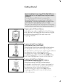
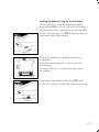
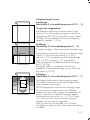
Preparing the AC Series Balance
In the following order, install the draft shield base
plate (4), the shield plate (3), the protective ring (2)
and the weighing pan (1) one at a time in the
weighing chamber.
Preparing the LC Series Balance
with a Round Glass Draft Shield
Place the draft shield base plate (4) on the balance.
Turn the plate clockwise until it snaps into place
(this procedure is necessary for preparing the balance
for operation with or without a dust cover).
Mount the pan support disk (26), the weighing
pan (1), the glass draft shield cylinder (25) and the
draft shield lid (24) one at a time on the balance.
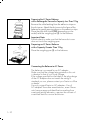
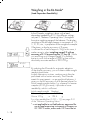
Preparing the LC Series Balance
with a Round Weighing Pan/GC 1201-G
Place the centering disk (27) on the balance.
Turn the disk clockwise until it snaps into place (this
procedure is necessary for preparing the balance
for operation with or without a dust cover).
Then mount the pan support disk (26) and the
weighing pan (1) one at a time on the balance
in the order given.
1–9
Preparing the LC Series Balance
with a Rectangular Pan and a Capacity Less Than 12 kg
Remove the white backing from the adhesive strips on
the dust cover. Attach the dust cover to the base of the
balance by gently pressing down on the adhesive strips.
Place the pan draft shield (28) (depending on the
model) and the weighing pan (1) on the balance.
Important Note:
Double check to make sure that the base dust cover
does not touch the weighing pan.
Preparing an LC Series Balance
with a Capacity Greater Than 12 kg
Place the weighing pan (1) on the balance.
Connecting the Balance to AC Power
The balance is powered by an AC adapter.
Make sure that the voltage rating printed on this unit
is identical to that of your local voltage.
If the voltage specified on the label or the plug design
of the AC adapter does not match the rating or
standard you use, please contact your Sartorius office
or dealer.
Use only original Sartorius AC adapters. Use of
AC adapters from other manufacturers, even if these
units have an approval identification marking from
a national testing laboratory, requires the consent of
a certified Sartorius service technician.
1–10
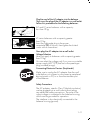
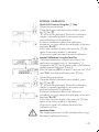
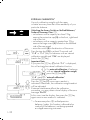
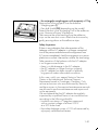
Plug the cord of the AC adapter into the balance.
Then insert the plug of the AC adapter in a wall outlet.
Follow this procedure for the following balances:
AC and LC series balances with a capacity
less than 12 kg
LC series balances with a capacity greater
than 12 kg:
Insert the right-angle plug in the power
receptacle (19) as shown, then tighten the slotted
screw with a screwdriver.
Now plug the AC adapter into a wall outlet.
230 V~
115 V~
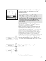
Voltage Selection
(does not apply to balances with a capacity greater
than 12 kg)
You can select the voltage only if you use our portable
power supply (6971172) that has a European-type
plug (rounded prongs).
Connecting Electronic Devices (Peripherals)
Make sure to unplug the AC adapter from the wall
outlet before you connect or disconnect a peripheral
device (printer or PC) to or from the interface port
of the balance.
Safety Precautions
The AC adapter, rated to Class 2 (double insulation),
can be plugged into a wall outlet without taking
any additional safety precautions. The pole of the
output voltage is connected to the balance housing,
which can be grounded for operation.
The interface is also electrically connected to the
balance housing (ground).
1–11
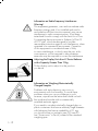
Information on Radio Frequency Interference
!
Warning!
This equipment generates, uses and can radiate radio
frequency energy and, if not installed and used in
accordance with the instruction manual, may cause
interference to radio communications. It has been
tested and found to comply with the limits for a Class
A computing device pursuant to Subpart J of Part 15
of FCC rules, which are designed to provide
reasonable protection against such interference, when
operated in a commercial environment. Operation
of this equipment in a residential area is likely
to cause interference, in which case the user, at his
own expense, will be required to take whatever
measures may be required to correct the interference.
Adjusting the Display Unit of an LC Series Balance
with a Capacity Greater Than 12 kg
Tilt the display unit to adjust it to the position
you desire.
Information on Weighing Electrostatically
Charged Samples
Problems with static electricity can occur in
environments with low humidity. To avoid these
problems when you use your balance in such
an area, wipe down the entire draft shield on both
the inside and outside with a commercially
available antistatic agent.
If you need to use electrostatically charged glass or
plastic containers that have a relatively large diameter
with balances that have a readability of 0.1 mg,
you should utilize our antistatic pan (155 mm Ø –
see “Accessories” in Part 6) instead of the standard
weighing pan.
1–12
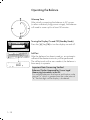
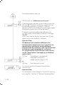
Leveling the Balance Using the Level Indicator
At the point of use, level the balance using the
leveling feet (21) as follows so that the air bubble is
centered within the circle of the level indicator (17):
Screw in the auxiliary foot (22) located on the front
right-hand side of the balance.
To level the balance using the level indicator
as a guide:
Extend the leveling feet (turn clockwise) to lift
the balance.
Retract the feet (turn counterclockwise) to lower
the balance.
Afterwards, extend the auxiliary foot (22) until it
touches the surface on which the balance is resting.
1–13
Operating the Balance
Warmup Time
After initially connecting the balance to AC power
(or after a relatively long power outage), the balance
will need to warm up for at least 30 minutes.
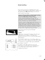
Turning the Display On and Off (Standby Mode)
Press the e key (14) to turn the display on and off.
Self-Test
After the balance has been turned on, an automatic
self-test of the electronic circuitry will be performed.
The self-test ends with a zero readout; the balance is
then ready to operate.
Important Note Concerning Verified
Balances/Scales Approved for Use as Legal
Measuring Instruments in the EU:
For verified balances that have a verification scale
interval “e” which is greater than the scale interval
“d,” the last digit on the display is bordered.
1–14
The weight display shows the following special codes
for your information:
OFF
The balance was disconnected from AC power
(i.e., power failure or outage; the balance
was disconntected, then reconnected to AC power).
O (STANDBY)
The display has been turned off using the e key (14),
and the balance is now in the ready-to-operate mode
and does not require warmup.
b (BUSY)
Once you have turned on the balance, the b symbol
will remain displayed until you press a key. During
operation, this symbol indicates that the balance
processor is still busy processing a given function and
will not accept another command to perform any
other function at this time.
R1 or R2
The number in the R code identifies the particular
weighing range you have selected.
W
Symbol for the selected application (in this case, the
weighing mode).
CAL I
The balance has an internal calibration weight.
1–15
Taring
A weight can be accurately measured only from
a defined zero point. Press one of the two t keys (10)
to zero the display. You can tare the display within
the entire weighing range.
Important Note Concerning Verified
Balances/Scales Approved for Use as Legal
Measuring Instruments in the EU:
The small circle on the left in the weight display
shows that the balance/scale has been exactly
tared to “0” (±0.25 of a scale interval).
Weighing
Place your sample on the weighing pan (1) to
determine the weight. Read off the weight indicated
in the display (6) only once the weight unit/stability
symbol (“g”, “kg” or a different unit as selected – see
Part 2, “Balance Operating Menu”) is indicated.
Important Note Concerning Verified
Balances/Scales of Accuracy Class k
To avoid measuring errors, the respective air density
must be allowed for. The following formula is used to
calculate the mass of the sample:
m = nw
1– ρL/8000 kg m–3
1– ρL/ρ
m = mass of the sample
nw = weight readout
ρL = air density during weighing
ρ = density of the sample
1–16
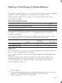
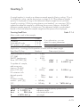
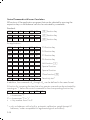
Weighing Range Structure
6200g
0.01g
SuperRange
(identified by S in the model designation AC/LC.....S)
“Single wide-range balance”
SuperRange models have an extraordinarily high
resolution; i.e., the weighing range has a resolution
ranging from 100,000 to a few million digits. There is
one level of fine readability for the entire weighing
range (for example: 0.01 g).
3200g
0.1g
DualRange
(identified by D in the model designation LC.....D)
2 weighing ranges: a fine range and a standard range
1000g
0.01g
4800g
0.1 g
3000g
0.05 g
0.00 g
1600g
0.02 g
800g
0.01 g
The balance automatically switches from the fine range
which is 10 times more accurate (e.g.1,000 g
capacity – 0.01 g readability) to the standard range
(e.g., a 3,200 g capacity – 0.1 g readability)
when the balance is loaded beyond the fine range
limit (>1,000 g).
The weight readout is displayed with the lower
readability of the standard range until you tare in the
fine range (<1,000 g).
PolyRange
(identified by P in the model designation AC/LC.....P)
PolyRange models have a wide weighing range
with multiple levels of accuracy that change as the
load increases or decreases.
The PolyRange function divides the weighing range
into as many as 4 ranges, each with a different
readability. In the various ranges, the readability will
adjust so that the last numeral of a weight readout
is displayed with a resolution of 1, 2, 5 or 10 digits
(10 = only the next to the last numeral displayed
changes; the last numeral is blanked).
After you press the tare key (10), you will obtain
the highest possible resolution, even when the balance
is loaded.
1–17
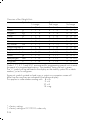
Weighing in the IQ-Mode*
(Load-Dependent Readability)
In the IQ-mode, weighing is done with a loaddependent readability of 0.1% (for different settings,
see part 2, “Balance Operating Menu”) throughout
the entire weighing range of the balance. The display
resolution of the last digit changes in increments of 1, 2,
5, 10, 20, etc., in proportion to the weight of a sample.
Oftentimes, a display accuracy of 2 grams
is sufficient for a load of approx. 2 kg. In this case, it
makes sense to select weighing range R 2 with an
accuracy of 0.1% by pressing the w key (8). While
you are filling up to a target weight, it is certainly
easier to work with a target of 2220 g than with an
absolutely accurate readout of 2219.92 g.
By selecting the IQ-mode for automatic adaption
of the display accuracy, you will obtain stable weight
readouts even faster.
In daily laboratory routines, analyses must often be
performed with a certain accuracy. The IQ-mode
meets this requirement – on an analytical balance, it
gives you the full accuracy of all 4 decimal places for
initial sample weights below 1 g, whereas for heavier
samples (of 100 g or more), it provides a lower
readability, which is sufficient:
Initial sample weight Readout
Below
1g
→
0.9876 g
Above 100 g
→ 123.4
g
For other readabilities (0.01% – 1%) see page 2–11
of the “Balance Operating Menu.”
* = not applicable to verified balances approved for
use as legal measuring instruments in Europe; on
GC 1201 G scales, menu code 3 2 9 must be set
1–18
Adjustment/Calibration
During calibration1), the balance is adapted to
changes in ambient conditions.
You should recalibrate your balance each time you
set it up in a different area or when the ambient
conditions (such as the temperature or the barometric
pressure) have changed.
Independent of such changes, you should calibrate
balances acceptable for legal metrological
verification at least once a day (i.e., even when
the ambient conditions remain constant). To meet the
highest requirements for accurate weighing, we
recommend that you calibrate the balance before
each weighing series.
The balance offers you various calibration functions.
The function you select is indicated in the display
by one of the following codes:
“CAL” : calibration function is activated
“C– I” : internal calibration
“C– E” : external calibration
“C– t” : sensitivity test
“CAL I”: the balance has an internal
calibration weight
You can use the c key (13) to interrupt any
calibration process.
1
) “Calibration” technically means to determine
the difference between the balance readout and
the actual weight on the pan to determine the
accuracy. Adjustment means to bring a balance
into the state of accuracy required for its use.
Therefore, “calibration,” as used in this manual,
actually means “adjustment.”
1–19
The balance may or may not have an internal
calibration weight:
– On standard balances, it depends on the model
(see Part 6, “Specifications”)
– Verified balances generally have an internal
calibration weight
Using Verified Balances/Scales as Legal
Measuring Instruments in the EU:
Before using your balance as a legal measuring
instrument, you must carry out an “Internal
Calibration” operation at the place of installation
after the warmup period.
1–20
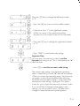
INTERNAL CALIBRATION
Quick-CAL Function Using the f Key:
Unload the pan and tare.
Once the display indicates a zero readout, press
the f key (7).
“C” will now be displayed. The built-in calibration
weight is internally applied by servomotor and
removed at the end of calibration.
If external interference affects the calibration
procedure, you may obtain a brief display of the error
message “Err 02.”
In this case, tare the display; then press the f key
again once a zero readout is indicated.
An acoustic signal indicates the end of calibration.
2 sec.
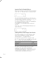
Internal Calibration Using the Tare Key:
Calibrate the balance using the tare control if an
application program (such as “tare memory”) is
assigned to the f key by menu code in the balance
operating menu (see parts 2 and 4).
Press the tare key (10) for at least 2 seconds until “C– I”
and “CAL” are displayed (next to the f key).
Unload the pan and tare.
Once the display indicates a zero readout, press
the f key (7).
“C” will now be displayed. The built-in calibration
weight is internally applied by servomotor and
removed at the end of calibration.
If external interference affects the calibration
procedure, you may obtain a brief display of the error
message “Err 02.”
In this case, tare the display; then press the f key
again once a zero readout is indicated.
An acoustic signal will indicate the end of the
calibration process.
!
Important Note:
The weighing pan must be left unloaded when using
the internal calibration function.
1–21
EXTERNAL CALIBRATION*
Use only calibration weights with the same
or better accuracy than that of the readability of your
particular balance.
Unlocking the Access Switch on Verified Balances/
Scales of Accuracy Class k:
– on balances with a capacity less than 12 kg,
remove the protective cap (5) on the front, right-hand
side of the unit
– on balances with a capacity greater than 12 kg,
remove the large screw (5) located on the left-hand
side of the rear panel
– move the switch (5) in the direction of the arrow
2 sec.
Press the tare key (10) for at least 2 seconds until
“C– E” or “C– I” (only for balances with an internal
calibration weight) and “CAL” are displayed
(next to the f key).
Important Note:
If you press the f key (7) while “C– I” is displayed,
this will activate the internal calibration function.
For external calibration of balances
with an internal calibration weight,
press the F key (12).
“C– E” stands for “external calibration.”
Unload the balance and tare.
Press the f key (7) once a zero readout is
indicated. Afterwards, the calibration weight readout
will be indicated.
If external interference affects the calibration
procedure, you may obtain a brief display of the error
message “Err 02.”
In this case, tare the display; then press the f key
again once a zero readout is indicated.
* = For accuracy class K verified precision
balances/scales, this function is allowed to be
used only if the balance is not being operated
as a legal measuring instrument.
1–22
Center the calibration weight on the weighing pan.
An acoustic signal will indicate the end of the
calibration process.
Important Note for Accuracy Class K
Verified Balances/Scales Approved for Use
as Legal Measuring Instruments in the EU:
After verification, the “external calibration” function
is blocked by the access switch (5) (adjusted
to the left and secured against alteration of the
switch setting).
SENSITIVITY TEST (special function for balances
with a built-in calibration weight)*
Rather substantial changes in barometric pressure
and temperature may affect the display response
of these highly accurate balances. To ensure that you
obtain the full accuracy of these balances, even
when you use the entire weighing range, we have
implemented a sensitivity test function. It will help
you decide quickly whether or not you need to
recalibrate your balance (for example, to maintain the
same accuracy during long-term weighing series).
2 sec.
Press the tare key (10) for at least 2 seconds until
“C– I” and “CAL” are displayed (next to the f key).
Select the sensitivity test by pressing the
F key (12) twice.
* = Not on verified LC balances
1–23
Unload the balance and tare.
“C– t” stands for “calibration sensitivity test.”
Once the display indicates a zero readout, press the
f key (7). The built-in calibration weight will now
be internally applied by servomotor. Then the
deviation of the current readout from the target weight
(displayed in grams only) will be indicated.
If external interference affects the calibration test,
you may obtain a brief display of the error message
“Err 02.”
In this case, tare the display; then press the f key
again once a zero readout is indicated.
Important Note:
The balance/scale should be calibrated if the
deviation of the readout from zero is more than the
reproducibility specified for standard balances
and more than the verification scale interval specified
for balances/scales acceptable for verification.
For reproducibilities and verification scale intervals,
see the “Specifications” that apply to your balance/
scale in Part 6.
f key:
or
F key:
The balance is automatically
calibrated by the built-in
weight (see also page 1–21).
Quits the sensitivity test
An acoustic signal will indicate the end of the
sensitivity test.
Important Note:
For information on the setting for “Quick-CAL sensitivity
test using f,”see Part 2, “Balance Operating Menu.”
1–24
Data Interface
If you wish to record your weighing results using
a Sartorius Data Printer, plug the printer connector into
the interface port (20) of the balance. You do not
need to adjust any settings.
Important Note for Balance/Scale Models Verified
for Use as Legal Measuring Instruments:
When using the balance/scale as a legal
measuring instrument (legal for trade), you are
allowed to connect to it only peripherals authorized
by law. However, if you are not using the
balance/scale as a legal measuring instrument, you
may connect to it any peripherals you wish, e.g.,
additional displays, personal computer, etc. Such
peripherals must be marked to indicate that they are
not allowed to be used when the balance/scale is
being used as a legal measuring instrument.
Remove the protective cap from the data
interface port.
Caution:
Make sure to unplug the AC adapter from the wall
outlet before you connect or disconnect any
peripherals (printer or PC) to or from the interface port
of the balance.
To print data on hard copy or have them output onscreen on an on-line computer, press the p key (11).
For information on special data output parameters,
see “Utilities” in Part 2.
For details on the data interface (such as the
data output or input formats, pin assignment, etc.)
or on interfacing a remote display, see Part 5,
“Interface Description.”
1–25
Interfacing Devices with the Balance
Please note that the interface port is electrically
connected to the protective grounding conductor
of the balance housing. The interface cables supplied
as standard equipment are shielded, and both ends
of each cable are electrically connected to the
connector cases. This connection may result in interference caused by ground loops or by transient
currents if you have grounded the housing or
connected the protective grounding conductor
for line power. If necessary, connect an equipotential
bonding conductor to the balance.
1–26
Below-Balance Weighing
A port for a below-balance weighing hanger is
located on the bottom of the balance (for LC balances
with a capacity greater than 12 kg, see “Accessories”
in Part 6).
To fasten the hanger, open the below-balance port by
turning the cover plate.
Now you can attach a sample to the hook using a
suspension wire, for example. Common applications
for below-balance weighing include density
determination or immersing a sample in a special
atmosphere (medium for reaction).
When you use such below-balance weighing
hangers, you must install a draft shield (especially
on analytical balances).
Important Note for Verified Balances/Scales
Approved for Use as Legal Measuring Instruments
in the EU:
When a verified balance/scale is being used
as a legal measuring instrument, the below-balance
weighing port may not be opened.
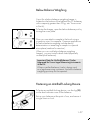
Fastening an Antitheft Locking Device
To fasten an antitheft locking device, use the lug (18)
on the level indicator case of the balance.
Set up your balance at the point of use, and secure it
using a chain or lock.
1–27
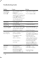
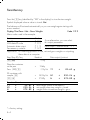
Troubleshooting Guide
Problem ...
No segments
are indicated
in the weight
display (6)
The display
indicates “L”
The display
indicates “H”
The display briefly
indicates “Err 02”
The special code
“C” displayed
does not go out
Causes ...
– No AC power is available
– The AC adapter is not
plugged in
– The balance was disconnected from AC power while
in the standby mode “o” or
turned “off” (display
backlighting turned off) and
was reconnected to AC
power <2 minutes later
– The weighing pan (1)
is not in place
– The load exceeds
the capacity of the balance
– A zero readout was not indicated when the f key (7)
was pressed to calibrate
– The balance is loaded
– The balance is not
ready to calibrate or is in
the warmup phase
– The weighing system
is affected by
drafts or vibrations
– The draft shield is
not closed
The weight
readout is
obviously
wrong
1–28
– The balance has not
been calibrated
– The balance was not
tared before weighing
– The air bubble of the
level indicator (17) is not
centered within the circle
Solution
– Check the AC power supply
– Plug in the AC adapter
– Press the e key (14)
– Position the pan
– Unload the balance
– Press the tare key (10);
then press the f key again
– Unload the balance
– After connecting the balance
to AC power via the
AC adapter, let the balance
warm up for at least 30 min.
– Access the menu to
select the appropriate
code to adapt the balance
to the particular weighing
environment (see Part 2)
– Check the draft shield
(place the lid (24) on the
shield or close the doors of
the draft shield chamber)
– Calibrate
(see pages 1–19ff.)
– Tare before weighing
– Level the balance
(see page 1–13)
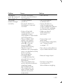
Problem ...
The special
code “b“ displayed
does not go out
The weight
readout changes
constantly
Causes ...
– No keys have been
pressed since the balance
was turned on
– Unstable ambient
conditions
– Too much vibration or
the balance is exposed
to a draft
– A door of the draft
shield chamber is not
completely closed
(only applies to draft shields
with sliding doors)
– The round glass draft
shield is not in place
– The draft shield base
plate (4) or the centering disk (27) is
not mounted correctly
– The dust cover for
balances with a rectangular
pan is not attached correctly
and is touching
the weighing pan
– A foreign object
is caught between the
pan and the housing of
the balance
– The cover plate for the
port for the below-balance
weighing hanger
has not been closed
– The sample does not
have a stable weight
(absorbs moisture or
evaporates)
Solution
– Press any key
– Set up the balance
in another area
– Access the menu to
select the appropriate
code to adapte the balance
to the particular weighing
environment (see Part 2)
– Make sure that all
draft shield doors
are closed
– Position the round
draft shield
– To mount these components,
see “Getting Started”
on page 1–9
– Press down on the adhesive
strips to attach the dust cover
– Remove foreign object
– Turn the cover plate to
close the port for
below-balance weighing
1–29
Care and Maintenance
Servicing
Regular servicing by a Sartorius service technician
will extend the service life of your balance and insure
its continued weighing accuracy. Sartorius can
offer you service contracts with your choice of regular
maintenance intervals ranging from 1 month to 2 years.
Cleaning
Before cleaning the balance, unplug the AC adapter
from the wall outlet (mains supply).
Please do not use any aggressive cleaning agents
(solvents or similar agents). Instead, use a piece of cloth
which has been wet with a mild detergent (soap).
If your balance has a round glass draft shield,
avoid generating static electricity by wiping and
rubbing the glass. After cleaning, decharge the round
glass draft shield to eliminate static electricity, for
example, by wiping off all surfaces with a damp and
grounded piece of cloth.
Make sure that no liquid enters the balance housing.
After cleaning, wipe down the balance with a soft,
dry piece of cloth.
Changing the Dust Cover for LC Series Balances
If the dust cover is dirty, change it as follows:
– for round weighing pans (with or without a
round glass draft shield)
Remove the following parts from the balance:
– Draft shield lid (24)
– Glass cylinder (25)
– Weighing pan (1)
– Pan support disk (26)
Turn the centering disk (27) or the draft shield base
plate (4) until it snaps out of place and lift it off.
Then exchange the old dust cover for the new one.
Place the centering disk or the draft shield base plate
on the balance. Turn the disk or plate clockwise
until it snaps into place.
1–30
– for rectangular weighing pans with a capacity <12 kg
Remove the following parts from the balance:
– Weighing pan (1)
– Pan draft shield (28) (depending on the model)
Detach the dust cover by peeling it off at the adhesive
strips. Remove all traces of adhesive.
Then remove the white backing from the adhesive
strips on the new dust cover. Attach the dust cover by
gently pressing down on the adhesive strips.
Safety Inspection
If there is any indication that safe operation of the
balance with the AC adapter is no longer warranted,
turn off the power and disconnect the equipment from
AC power immediately. Lock the equipment in a secure
place to ensure that it cannot be used for the time being.
Safe operation of the balance with the AC adapter
is no longer ensured when
– there is visible damage to the AC adapter
– the AC adapter no longer functions properly
– the AC adapter has been stored for relatively
long periods under unfavorable conditions.
In this case, notify your nearest Sartorius Service
Center or the International Technical Support
Department based in Goettingen, Germany. Only
service technicians who are authorized by Sartorius
and have access to the required maintenance manuals
are allowed to perform maintenance and repairwork
on the equipment.
We recommend that the AC adapter be regularly
inspected by a qualified Sartorius service technician
according to the following checklist:
– Insulation resistance >7 megohms measured
with a constant voltage of at least 500 V
at a 500 kohm load
– Equivalent leakage current < 0.05 mA measured by
a properly calibrated multimeter
1–31
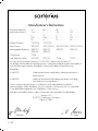
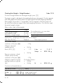
Manufacturer’s Declaration
Electronic Balances
and Scales (Series):
AC.....-....
CM.....-.....
I.....-.....
MC.....-.....
RC.....-.....
BA.....-.....
F.....-....
IC.....-.....
PMA.....-.....
S.....-.....
Remote Displays:
737101A
737102A
Data Printers:
YDP01PT
YDP02-0DV1 YDP02-0CEV2 YDP02-0CEV3
Rechargeable Batteries: YRB01PT
YRB04Z
T-Connector:
7258
Foot, Hand Switches:
YPE01RC
BP.....-.....
GA.....-.....
L.....-.....
PT.....-....
TS.....-.....
C.....-.....
GC.....-.....
LC.....-....
QS.....-....
XX.....-.....
YRB01Z
YRB05Z
YRB02Z
YRB03Z
YPE01Z
7226
7252
Pursuant to the European Directive 73/23/EEC, particularly to Article 10,
we declare that the above listed equipment is manufactured and tested in accordance
with the following European Standards in force at the date of manufacturing.
Standards:
EN 60742
Isolating transformers and safety isolating transformers;
Requirements
EN 60950
Safety of information technology equipment including
electrical business equipment
If you use electrical equipment in installations and under ambient conditions
requiring higher safety standards, you must comply with the provisions as specified
in the applicable regulations for installation in your country.
Warranty and liability claims under civil law are not covered by this declaration.
Sartorius AG
D-37070 Goettingen, Germany
March 3, 1994
Oldendorf
OA-113-8/12.93
1–32
Dr. Maaz
Balance Operating Menu
This Sartorius balance can do much more than “just weigh.”
It can “think” in various units of measure, adapt to unfavorable conditions and
process weight data for a variety of applications.
In the operating menu, you can define how your balance will adapt to ambient
conditions, and also how it will work to meet your special requirements.
For your convenience, the menu codes have been factory-set so that you normally
do not have to make any changes. If you have special operating conditions,
adjust the balance to your individual requirements by setting the menu codes of
your choice.
The factory-set menu codes are identified by an “*.” You can select the functions not
identified by an “*” by setting the respective menu code.
Don’t worry!
Even if you’ve selected the “wildest” codes and totally thrown off all the code
settings you need, all you have to do is press a key to set things straight again.
Your balance will work just like it did when it left the factory – with the original
factory-set menu codes.
Important Note for Verified Balances/Scales Approved for Use as Legal
Measuring Instruments in the EU:
The balance/scale operating menu can also be changed when the balance/
scale is being used as a legal measuring instrument (legal for trade). As a rule,
codes that are not permitted for operation of the balance/scale as a legal
measuring instrument are blocked or not displayed. The operating menu on
verified balances/scales cannot be locked with the menu access switch
(“–” not displayed).
2–1
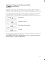
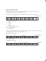
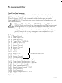
Changing a Menu Code Setting
To select specific functions, you will need to set the
respective menu code.
There are three steps to changing a code setting:
– Accessing the menu
– Setting a code
– Confirming and storing the code
The keys have special functions for setting a menu
code. To set a code, use the four keys which are
defined on the display as arrow points to indicate
the direction:
< w and > p = to move to the left and right
^ f and v F = to increase and decrease
a number by one with each press
t*
= to confirm a code setting
c
= to store a code setting and exit
the menu
Now try changing the weight unit in the second
weighing range from grams to “kg,” code 3 1 3.
Accessing the menu
– Turn the balance off
– Turn it back on again
– While all segments are displayed, briefly press the
tare key* (10)
– If -L- is displayed, unlock the menu as follows:
– on balances with a weighing range less than 12 kg,
remove the protective cap on the front, right-hand
side of the unit
– on balances with a weighing range greater than
12 kg, remove the large screw located on the
left-hand side of the rear panel to expose the menu
access switch (5)
– Move the switch (5) in the direction of the arrow.
* = Labeled “T” on standard LC series balances with
a capacity greater than 12 kg
2–2
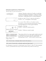
Press the f key to change the left-hand number
to “3”
– Press the p key to move to the middle number
– Now move from “1” to the right-hand number
(When you move to the right-hand number,
the previously set numeric code will be indicated).
– Press the f key to change the right-hand number
to “3”
– Press “TARE” to confirm the code setting
Important Note:
You must press the tare key in order to confirm
the code you have just set. This is indicated by the “o”
after the code.
– Press c to store the new menu code setting
The current code setting in the balance operating
menu is identified by a small “o” after the last number.
When you access the operating menu, the previously
set numeric code will be displayed after selecting
the left-hand and middle numbers, which means the
entire menu code setting is displayed. This makes
it easy for you to check the previously set menu codes.
If you would like to change several menu code
settings, you do not have to press c after each
change to leave the balance operating menu.
2–3
Important Note for Standard Balances:
Please do not forget to relock the balance operating
menu. The “-L-” indicates that it is currently locked:
You can lock the menu anytime you wish once you
have accessed it. However, it is best if you wait until
you have changed the last code setting.
To use the locking function, make sure code 8 1 2 is
set in the balance operating menu.
If code 8 1 1 is set, the menu access switch will
not lock.
In this case, “-C-“ will be displayed whenever you
access the menu:
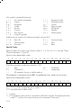
Undoing All Menu Code Changes: Reset Function
This function enables you to reset all menu codes
back to the original factory settings, which are
indicated by an “*” throughout part 2.
To activate this special function, set menu code
9 – – 1° and confirm by pressing t; press the c
key to store the code and leave the menu.
Reset function
Activated
Off
Code
9––1
9––2
The charts on the next pages give just a small
sampling of the code options available for
the balance operating menu. These options involve
standard balance operation, utilities for printouts
or data transfer, and additional functions.
2–4
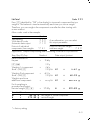
Balance Operating Parameters
Adapting the Balance to Ambient Conditions
To adapt your balance to ambient conditions, you may need to change the
response time (see “Product Data Sheets”).
Very stable conditions
Stable conditions
Unstable conditions
Very unstable conditions
Code
* 1 1
* 1 1
1 1
1 1
1
2
3
4
Standard Weighing Mode – Manual Filling Mode
You can optimally adapt your balance to meet either of these requirements.
In the manual filling mode, the display compensates for fluctuations of the load
on the balance so that you obtain a steadier readout.
Standard weighing mode
Manual filling mode
Code
* 1 2
1 2
1
2
Stability Range
The stability range in digits works together with the readout of the stability symbol
(unit symbol) when the load changes. When the stability symbol is displayed,
the weight readout is stable within the defined range.
Readout is stable within +/–
0.25 digit
0.5 digit
1
digit 2)
2
digits 2)
4
digits 2)
8
digits 1)
Code
1 3
* 1 3
1 3
* 1 3
1 3
1 3
1
2
3
4
5
6
* = factory setting; depends on the balance model in some cases
) = not applicable to verified balances approved for use as legal
measuring instruments
2
) = not applicable to the verified AC models only
1
2–5
Stability Symbol Delay
This setting allows your balance to compensate for individual interfering factors
which slowly subside, such as turbulent air currents generated within the weighing
chamber of an analytical balance. You can therefore choose to have the stability
symbol displayed later.
No delay
Short delay
Long delay
Extremely long delay
Code
1 4
* 1 4
1 4
1 4
1
2
3
4
Tare Parameter
You can define when the balance will perform the taring operation:
At any time
Not until the readout is stable
Only at stability
Code
** 1 5
* 1 5
1 5
1
2
3
Auto Zero Function
When this zero tracking function is activated, any changes off the zero readout
that are equal to a defined fraction of digits per second are automatically tared.
In other words, it ensures a stable zero.
Auto Zero on
Auto Zero off
Code
* 1 6
1 6
* = factory setting
** = not applicable to verified balances approved for use as legal
measuring instruments
2–6
1
2
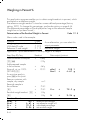
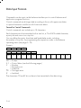
Weighing in Three Ranges on Standard Balances
The toggle key, labeled w, lets you switch back and forth between two weighing
ranges, R1 and R2, provided you are using the factory-set menu code.
When the menu code for “three ranges” is set, press the w key each time to
select a different range.
Selecting the Number of Ranges
Code
2 1
* 2 1
2 1
Block the w key/one weighing range
Two weighing ranges
Three weighing ranges1)
1
2
3
For codes 2 1 4 “counting” and 2 1 5 “weighing in percent,” see part 4,
“Application Programs.”
Any range that you select by pressing the toggle key will always be indicated by
an ID code in the display. This ID depends on the menu code setting.
Two weighing ranges
Three weighing ranges
1st range
R1
– – – **
ID code
2nd range
R2
R1
3rd range
R2
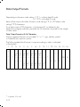
Weight Units
The “initial weight unit” is the unit in which your balance will weigh the moment you
turn it on. This unit is defined in the 1st range.
You can select a different unit for each weighing range by setting the appropriate
menu code.
Choose any weight unit you’d like, well almost any that’s reasonable for the
balance model you are using. For example, if you set the menu code for “kg”
on a 0.1 mg balance, you’ll obtain a readout sure enough, but the display
resolution might be slightly off.
* = factory setting
** = The standard weighing range automatically displayed when you turn on the
balance is identified by the scale pictogram in the display only.
1
) = factory setting on GC 1201-G scales only
2–7
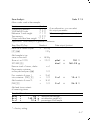
Overview of the Weight Units
Symbol
Grams
Grams*
Kilograms*
Carats
Pounds
Ounces
Troy ounces
Hong Kong taels
Singapore taels
Taiwanese taels
Grains
Pennyweights
Milligrams
o
g
kg
ct
lb
oz
ozt
tl
tl
tl
gr
dwt
o
1st range
1 7 1
1 7 2
1 7 3
1 7 4
1 7 5
1 7 6
1 7 7
1 7 8
1 7 9
1 7 10
1 7 11
1 7 12
1 7 13
Code
2nd range
3 1 1
3 1 2
3 1 3
3 1 4
3 1 5
3 1 6
3 1 71)
3 1 8
3 1 9
3 1 10
3 1 11
3 1 12
3 1 13
3rd range
3 3 1
3 3 2
3 3 3
3 3 4
3 3 5
3 3 6
3 3 7
3 3 8
3 3 9
3 3 10
3 3 11
3 3 121)
3 3 13
Codes 1 7 1, 3 1 1 and 3 3 1 are reserved for programming special units to meet
the needs of customized applications. The standard, factory-set unit is grams.
The “o” symbol will be indicated in the display as the stability symbol for a stable
readout, just as for milligrams.
Some unit symbols printed on hard copy or output on a computer screen will
differ from the way they are indicated in the balance display:
This applies to code numbers ending with 8 = tlh
9 = tls
10 = tlt
13 = mg
* = factory setting
1
) = factory setting on GC 1201-G scales only
2–8
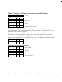
Weighing in Two Ranges on Verified Balances/Scales
Approved as Legal Measuring Instruments
The toggle key, labeled w, lets you switch back and forth between two weighing
ranges, R1 and R2, provided you are using the factory-set menu code.
Selecting the Number of Ranges
Code
2 1
* 2 1
Block the w key/one weighing range
Two weighing ranges
1
2
For codes 2 1 4 “Counting” and 2 1 5 “weighing in percent,” see part 4,
“Application Programs.”
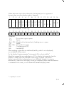
Weight Units
The “initial weight unit” is the unit in which your balance will weigh the moment
you turn it on. This unit is defined in the 1st range. You can select a different unit for
each weighing range by setting the appropriate menu code.
Choose any weight unit you’d like, well almost any that’s reasonable for the
balance model you are using. For example, if you set the menu code for “kg”
on a 0.1 mg balance, you’ll obtain a readout sure enough, but the display
resolution might be slightly off.
Overview of the Weight Units
Symbol
Grams
Kilograms**
g
kg
Code
1st range
1 7 2*
1 7 3*
2nd range
3 1 2*
3 1 3
** = factory setting; depends on the balance model in some cases
** = on LC balances only
2–9
Display Modes on Standard Balances
You can select the display mode that best meets your individual requirements.
The factory-set menu code is defined for the highest possible accuracy in the
1st weighing range. The menu code settings for all weighing ranges are listed
on the next page.
Final Readout Mode
If you are interested in the final readout only, you can select this mode by setting
code 2 5 1. A special symbol, “– –,” will be displayed in any weighing range until
the final stable readout is indicated. For the standard readout mode, set code
2 5 2 (all readouts).
Special readout mode “– –”
Special symbol “– –” for unstable readings when load changes
Standard digital readout mode
Code
2 5
* 2 5
1
2
Last Numeral Blanked When the Load Changes
As the load on your balance changes, the display resolution is reduced by a factor
of 10 so that you will obtain a faster and more stable readout.
In the process, the last numeral is blanked until the load stabilizes. Once the load
has stabilized, the readout is indicated again with the full display accuracy, which
means the last numeral is displayed.
Round-Off Function
You can define the level of accuracy by changing the display increments, also
called “scale intervals” (of the last numeral). The display increments possible are
as follows: 1, 2, 5, 10, 20, 50, etc.
Starting with the basic increments of a weight unit, the display accuracy can
be reduced by as many as three levels so that you will obtain a faster readout with
a reduced display accuracy. Display accuracy is reduced in relation to the
selected basic increment of the weight unit. Example: weight unit “ct” for carats
(5 increments) with code setting 1 8 3 → 10 increments.
To make this concept easier to understand, the three levels are designated as
“rounding factors” in the tables summarizing the various menu code settings.
IQ-Mode
(Load-Dependent Readability)
In the IQ-mode, weighing is done with a menu-definable, load-dependent
readability throughout the entire weighing range of your balance. In the process,
the display resolution of the last digit of the weight value changes in increments
of 1, 2, 5, 10, 20, etc., in proportion to the weight of the sample.
* = factory setting
2–10
This mode for adapting the display accuracy enables you to weigh with a constant
relative accuracy between 1% and 0.01% over the entire weighing range
of your balance. Select the load-dependent display accuracy independently for
each of the three weighing ranges. The accuracy selected is shown in the top
right-hand corner of the application display field.
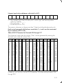
PolyRange Function (application for single-range balances)
The PolyRange function divides a single weighing range into as many as
4 ranges, each with a different readability. In the various ranges, the readability
will adjust so that the last numeral of a weight readout is displayed with
a resolution of 1, 2, 5 or 10 digits (10 digits = only the next to the last numeral
of the readout will change; the last numeral is blanked).
The PolyRange function makes filling easier because the readability becomes
slightly coarser as the load increases and you will not immediately lose an entire
place of readability.
Press the tare control at any range level to restore the full resolution of the first range,
even when the balance is loaded.
Display mode
Highest possible accuracy
Last numeral blanked when
load changes
Rounding factor 2
Rounding factor 5
Rounding factor 10
1%
accuracy
0.5% accuracy
0.2% accuracy
0.1% accuracy
0.05% accuracy
0.02% accuracy
0.01% accuracy
PolyRange function
1st range
*1 8 1
1
1
1
1
1
1
1
1
1
1
1
1
8
8
8
8
8
8
8
8
8
8
8
8
2
3
4
5
6
7
8
9
10
11
12
13
Code
2nd range
3 2 11)
3
3
3
3
3
3
3
*3
3
3
3
3
2
2
2
2
2
2
2
2
2
2
2
2
2
3
4
5
6
7
8
9
10
11
12
13
3rd range
3 4 11)
3
3
3
3
*3
3
3
3
3
3
3
3
4
4
4
4
4
4
4
4
4
4
4
4
2
3
4
5
6
7
8
9
10
11
12
13
* = factory setting
) = factory setting on GC 1201-G scales only
1
2–11
Display Modes on Verified Balances
You can select the display mode that best meets your individual requirements.
Final Readout Mode
If you are interested in the final readout only, you can select this mode by setting
code 2 5 1. A special symbol, “– –”, will be displayed in any weighing range
until the final stable readout is indicated. For the standard readout mode, set
code 2 5 2 (all readouts).
Special readout mode “– –”
Special symbol “– –” for unstable readings when load changes
Standard digital readout mode
Code
2 5
* 2 5
1
2
Last Numeral Blanked When the Load Changes
As the load on your balance changes, the display resolution is reduced by
a factor of 10 so you will obtain a faster and more stable readout.
In the process, the last numeral is blanked until the load stabilizes. Once the load
has stabilized, the readout is shown again with the full display accuracy, which
means the last numeral is displayed.
Code
Display mode
Highest possible accuracy
Last numeral blanked when load changes
1st range
*1 8 1
1 8 2
2nd range
*3 2 1
3 2 2
IQ-Mode
(Load-Dependent Readability)
The IQ-Mode does not apply to verified balances approved for use as legal
measuring instrument.
* = factory setting
2–12
Calibration Functions on Standard Balances
Select the appropriate menu code to define the access status for each of
the following calibration functions, which are activated by holding down the tare
key for a few seconds:
– External calibration
– Internal calibration
– Sensitivity test
C-E
C-I
C-t
If the menu access switch is unlocked (“accessible” status indicated by -C- after
you have accessed the balance operating menu), the “external calibration”
function will be accessible even though you have set the menu code 1 9 2 for
“access denied.”
External calibration
Accessible
Access denied
Code
* 1 9
1 9
1
2
Internal calibration
Accessible
Access denied
Code
* 1 10
1 10
1
2
Sensitivity test
Accessible
Access denied
Code
* 1 11
1 11
1
2
Quick CAL Using f
If your balance has a built-in calibration weight, you can select the “internal
calibration” function at any time by a touch of the f key (factory setting:
accessible). That’s why we call it “Quick CAL” for short.
You can also set a different menu code to change the function of the f key from
“internal calibration” to “sensitivity test.”
Both functions are accessible even if you select code 1 10 2 or 1 11 2, respectively.
Function of the f key
No function
Internal calibration (“CAL I”)
Sensitivity test (“CAL T”)
Code
* 2 2
* 2 2
2 2
1
5
6
For codes 2 2 2 to 2 2 4, see Part 4, “Application Programs.”
* = factory setting; depends on the balance model in some cases
2–13
Calibration Functions on Verified Balances/Scales
Select the appropriate menu code to define the access status for each of
the following calibration functions, which are activated by holding down the tare
control for a few seconds:
– External calibration
– Internal calibration
– Sensitivity test
C-E
C-I
C-t
External Calibration
Use the access switch to block or release the external calibration function.
External calibration
Accessible
Access denied
Switch set to
right
* left
On verified precision balances of accuracy class K, the “external calibration”
function is blocked by the access switch (adjusted to the left and secured against
alteration of the switch setting) after verification.
Quick CAL Using f
You can select the “internal calibration” function at any time by a touch of the f
key (factory setting: accessible). That’s why we call it “Quick CAL” for short.
On AC balances, you can also set a different menu code to change the function
of the f key from “internal calibration” to “sensitivity test.”
Function of the f key
No function
Internal calibration
Sensitivity test on AC balances
Code
* 2 2
* 2 2
2 2
For codes 2 2 2 to 2 2 4, see Part 4, “Application Programs.”
* = factory setting
2–14
1
5
6
Utilities for Printouts or Data Transfer
Sartorius balances come standard with an interface. You can plug a Sartorius
printer or a computer into this interface port to print data on hard copy or have
them transferred to your computer. Moreover, you can choose to output data from
your balance to this on-line device either automatically or by pressing the print
key on the balance.
The balance operating menu lets you define the various parameters for data output.
For information on the data formats and for interfacing a computer or other
peripherals, see Part 5, “Interface Description.”
Data Output Parameter
This parameter is coupled with the stability parameter =
stable readout or
no motion is detected
Print on request = data is output only when the print key is pressed or a software
command is received
Auto print = continuous, automatic data output
Print on request regardless of stability
Print on request after stability with storage of the function
Print on request at stability without storage of the function
Auto print regardless of stability
Auto print at stability
Code
6 1
* 6 1
6 1
6 1
6 1
1
2
3
4
5
Automatic Data Output
You can stop and start automatic data output by pressing the print key.
To avoid operating errors or to ensure that data will be output continuously in the
automatic mode, you can block this function.
Start/stop auto print using the p key
Auto print not stoppable
Code
6 2
* 6 2
1
2
* = factory setting
2–15
Data Output at Defined Intervals
You can reduce the volume of data in the “auto print” mode by defining the interval
at which data will be output automatically. This auto print interval is based on the
number of display updates.
Auto print interval
1 display update
2 display updates
5 display updates
10 display updates
20 display updates
50 display updates
100 display updates
Code
* 6 3
6 3
6 3
6 3
6 3
6 3
6 3
1
2
3
4
5
6
7
Automatic Taring after Data Output
This convenient setting lets you checkweigh a series of samples or products
without having to unload the balance after each weighing procedure. This means
less work for you:
– the sample remains on the pan after the weight readout has been printed or
transferred to an on-line computer
– the balance is tared automatically after the weight readout has been printed or
transferred to an on-line computer
– you simply load the next sample or part
Data output without automatic taring
Data output with automatic taring
* = factory setting
2–16
Code
* 6 4
6 4
1
2
Data ID Codes
To help you identify weights, piece counts, percentages, etc., a code letter is
printed or displayed in front of these values. For example, an “N” printed or
displayed in front of a weight value identifies it as a net weight. If you set the code
for “without data ID code,” only net weights, results in percent and counting
results will be output. You will find the data ID codes of a particular application
program listed in the corresponding description. The ID code increases the data
output format for each weight readout from 16 to 22 characters.
ID code for data output
Without
With
Code
* 7 2
** 7 2
1
2
** = factory setting
** = factory setting for the IAC version
2–17
Additional Functions
A number of additional menu codes enable you to assign or deny access to various
functions.
Menu Access Function on Standard Balances
You can define the function of the menu access switch on standard balances
by setting the code for the balance operating menu to “accessible.”
Access to the balance operating menu with standard balances
Accessible
Depends on the setting of the menu access switch
Code
8 1
* 8 1
1
2
Menu Access Switch Function on Verified Balances of Accuracy Class K
The balance operating menu can also be changed when the balance is being
used as a legal measuring instrument. Codes that are not permitted for operation
of the balance as a legal measuring instrument are blocked and cannot be
selected. The balance operating menu on verified balances approved for use as
legal measuring instruments cannot be locked with the menu access switch (“–”
not displayed). For balances of accuracy class K, the menu access switch is
adjusted to lock the “External Calibration” function after verification. To do this, the
switch must be moved to the left. A control seal is affixed to the balance to lock
the menu access switch. Unauthorized attempts to remove this seal will irreversibly
damage it. If you break the seal, the validity of the verification will become void,
and you must have your balance re-verified.
Beep Tone (Acoustic Signal)
If you wish, you can turn off the beep tone (i.e., acoustic signal)
Acoustic signal
On
Off
Code
* 8 2
8 2
1
2
Blocking the Keys
You can block all keys on the balance (except for e) by setting the respective code.
Key functions
Accessible
Blocked
* = factory setting
2–18
Code
* 8 3
8 3
1
2
Universal Switch for Remote Control
You can connect an external universal switch to the interface of your balance for
remote control of certain functions (listed below). Set the appropriate menu code to
define the function of this switch.
Functions
Print
Tare
f key
F key
Code
* 8 4
8 4
8 4
8 4
1
2
3
4
Analog Display: Bar Graph/Marker
In the factory setting, the analog display works as a bar graph. By changing
the menu code, you can turn the analog display completely off or have it appear
as a marker. When the marker is selected, two individual segments will move
within the display scale range to indicate the loading status of your balance.
Analog display
Off
Bar graph
Marker
Code
8 5
* 8 5
8 5
1
2
3
Power-On Mode
Depending on the operating mode, line current, battery operation or continuous
operation, you can change the power-on mode of your balance.
The factory setting is: (power) off –> on <–> standby.
In the setting “toggle between on and (power) off,” the balance remains off after
a power failure has occurred or after the balance has been disconnected from
AC power. After the balance has been turned off, power for the “standby” mode
is not available. In this setting, the balance can be turned on and off using
the e key.
* = factory setting
2–19
In the setting “toggle between on and standby,” the balance power will turn back
on automatically after a power failure has occurred or after you have disconnected
your balance temporarily from AC power.
In the setting “automatic power-on,” the balance will turn back on automatically
after a power failure has occurred; after the balance has been disconnected, then
reconnected to AC power; or after the e key has been pressed. In this setting,
the balance can no longer be turned off using the e key.
Power-on mode
(Power) off –> on <–> standby
On <–> (power) off
On <–> standby
Automatic power-on
Code
* 8 6
8 6
8 6
8 6
1
2
3
4
Automatic Shutoff (Battery Saver) for Use with Code 8 6 2 or the
Rechargeable Battery Option**
If you are using the rechargeable battery option, turn the automatic shutoff function
on to increase the hours of battery operation so that you do not need to recharge
the batteries that often. Here is how the battery saver function works: If there has
not been a change in a weight readout for at least 2 minutes or you have not
pressed any keys during this time, “b” will be displayed. After another 2 minutes,
the balance will shut off if it has not been used in the meantime.
Automatic shutoff
On
Off
Code
8 7
* 8 7
1
2
Display Backlighting
Depending on your individual workplace requirements, you can turn the display
backlighting on or off accordingly.
Display backlighting
On
Off
Code
* 8 8
8 8
** = factory setting
** = not applicable to verified balances approved for use as legal
measuring instruments
2–20
1
2
“isoCAL” Self-Calibrating Function*
on AC/LC…-00MS/-0CEMS Models
Range of Performance Features
The AC/LC…-00MS/-0CEMS models have
standard features which are not offered by other
balances and scales of the
product line:
– Built-in servomotor for application of the internal
calibration weight(s)
– Self-calibrating function – “isoCAL”
– ISO/GLP-compliant printout/record
– Integrated Applications Computer “IAC” for the
application programs:
tare memory; formulation;
statistics; weighing in percent; counting; clock and
timer for time-controlled measurements/weighing;
calculation of weight values; totalling of weights;
averaging/animal weighing; density determination;
over/under checkweighing; ID number for
identification of data
Important Note for Verified Balances/Scales
(…-0CEMS):
These models are allowed to be used in the extended
ambient temperature range of 0°C to +40°C as
long as not otherwise indicated on the verification ID
label.
* = Balances of the
product line cannot
be upgraded with this function
3–1
“isoCAL” Self-Calibrating Function
A balance of the Master Series can self-calibrate.
The self-calibrating function is activated based on the following parameters:
Model
AC 211 S-00MS, AC 211 P-00MS,
AC 121 S-00MS
LC 3201 D-00MS, LC 1201 S-00MS
LC 621 S-00MS, LC 621 P-00MS,
LC 6201 S-00MS, LC 4201 S-00MS,
LC 4801 P-00MS
LC 221 S-00MS, LC 2201 S-00MS,
LC 2201 P-00MS, LC 34000 P-00MS
LC 821-00MS, LC 421-00MS,
LC 16000 S-00MS, LC 12001 S-00MS,
LC 6201-00MS, LC 4201-00MS,
LC 34-00MS
When the temperature changes
After a calibration
interval of
1.5 kelvin
1.5 kelvin
4h
4h
2 kelvin
6h
4 kelvin
12 h
4 kelvin
24 h
These parameters are the same for the corresponding balance/scale models
that have been verified or are acceptable for legal metrological verification (models
AC/LC…-0CEMS).
In addition, the self-calibrating function is activated after an hour has passed
since the balance was connected to AC power (power on) and after an hour has
passed since the time was set.
If the balance self-calibrates due to a change in temperature, the timer for the
calibration interval is set back to zero. The timer for the calibration interval is also
active when the balance is in the standby mode. After the balance has been
turned on, a check is run to see if a calibration time was exceeded while the
balance was in the standby mode.
Flashing W Symbol
If the “W” symbol flashes, the balance wants to self-calibrate. You do not need to
interrupt your weighing series, because the balance will wait until you have
unloaded the weighing pan (at least to approx. 2% of maximum capacity) and
have not used the balance for two minutes. Then the balance will self-calibrate.
The W symbol flashes until the balance begins self-calibration or until you activate
the calibration function manually (see also “Calibration” in Part 1).
You can interrupt the calibration process at any time by pressing the c key.
If any external disturbance affects self-calibration, the error code “Err 03”
will be displayed, and the procedure will be interrupted by two beep tones.
After two minutes, the self-calibrating function will restart.
3–2
Important Note for Verified Balances/Scales Approved as Legal Measuring
Instruments (…-0CEMS):
If “C” is indicated in the display or “STAT C”
is output via the interface, the balance/scale must not
be loaded.
The balance/scale initiates self-calibration 15 seconds after “C” is indicated
in the display. Changing loads during these 15 seconds will interrupt the internal
preparation cycle for calibration.
You can select the following menu codes:
Self-calibrating function – “isoCAL”
OFF1)
Calibration symbol “W” in the display only1) 2)
ON – “isoCAL” with clearing of values determined
for application programs3)
ON – “isoCAL” without clearing of values determined
for application programs
Code
1 15 1
1 15 2
1 15 3
*1 15 5
1
) Not applicable for verified balances/scales approved as legal measuring
instruments (…-0CEMS)
2
) When code 1 15 2 is set, the “W” symbol will flash in the display until you
activate the calibration function manually.
3
) Reference values for the application programs have to be stored once again
after self-calibration has been performed (e.g., for counting or weighing in
percent). Measured values calculated for statistics or totalling will be deleted
after the calibration process has been performed.
Activating Internal Calibration Manually
The “Quick-CAL” key functions and “Internal Calibration Using the Tare Key”
are described Part 1.
*= factory setting
3–3
Automated Processes
Delays in production may occur when the “isoCAL” function is used in automated
processes. You can avoid such delays by setting menu code 1 15 2 “Calibration
symbol “W” in the display only.” In this case, you have to press the key to
activate calibration.
Printout or Record of Calibration Processes
The balance, interfaced with a data printer or a computer, creates a document
that records the date, time, serial number and model number which makes it
possible to clearly trace data to the balance that generated it. For more information,
see the section entitled “ISO/GLP-compliant Printout or Record” in the IAC
instruction manual.
Calibrating Balances When Using YDK 01, YWP 01, YWP 01 U
or YWP 02 Accessories
When you use the YDK 01 density determination kit or one of the special weighing
pans, YWP 01, YWP 01 U or YWP 02, the balance cannot self-calibrate.
If the “W” symbol flashes, place the standard weighing pan on the balance and
activate the calibration function manually.
Self-Calibration with the MC1-MP8 Interface (Binary Converter)
EC-approved balance/scale models (…-0CEMS) can self-calibrate also when
menu code 9 2 3 for the MC1-MP8 interface (binary converter) has been set.
On all other models, if you select the MC1-MP8 interface, the balance cannot selfcalibrate. If this is the case, activate the calibration functions manually.
3–4
Application Programs for Balances of the
Product Line
In addition to the functions implemented strictly for weighing, Sartorius balances
of the MC1 product line offer you a variety of application programs to handle
tough daily routine work in the laboratory as well as in industrial plants. If you have
not yet experienced how fast and accurately a Sartorius balance can count parts
or convert weights into percentages, now is a good opportunity to try it out.
In this description, you’ll find a few simple examples for the following applications:
Tare memory
Weighing in percent
Over/under checkweighing
Counting
You can also use “tare memory” and “over/under checkweighing” in combination
with “weighing in percent” or “counting.”
If your balance has a numeric keypad, please use the instructions entitled “IAC”
or “Backweigher” supplied with the balance.
4–1
To select an application program or a specific function, set the appropriate code
in the menu. Part 2 describes in detail how to set menu codes.
Additional settings for running the particular program and displaying or printing the
data on hard copy are listed in a table of codes.
One thing you should do when you want to set the code for a different program,
or when someone else has already operated the balance is:
Select the reset function – code 9 – – 1o – to change all menu codes back to the
original factory settings.
Using Verified Balances/Scales as Legal Measuring Instruments in the EU:
All application programs can be selected on balances used as legal measuring
instruments. Non-metric values are indicated as follows:
Percent
=%
Piece count (counting) = pcs
Computed value
=o
Functions Common to All Programs
The f, F and w keys are assigned different functions by the individual
programs. In each case, the functions currently assigned to the f and F keys
are always identified in the display next to each key.
c Key
c clears the program function and resets the program.
Clear function
Global – clears functions of all keys
Selective clearing in the order of f → F
Code
* 2 4
2 4
1
2
Use the selective code if you intend to run two different programs at the same time.
Select code 2 4 2 if you would like to clear the program assigned to the f key
before you clear the program assigned to the F key.
* = factory setting
4–2
Information and Printouts or Data Transfer
The info key (i) has two functions:
– one brief press:
– one long press:
displays information and prints/transfers stored data
recalls the reference percentage or reference sample
quantity for weighing in percent or counting (for more
information, see the descriptions of these programs)
Briefly press the i key to select the information
function: an “i” will appear in the display.
If you press f or F now, the data stored in
the memory will be retrieved and displayed. What is
displayed depends on the program selected.
Example: Counting
Readout: Reference sample quantity
Readout: Reference sample weight
nRef
+ xxxxxxx pcs
wRef
+ xxxxxxx g
Data output only for
Code 7 2 2
These data will also be output via the interface (printed
or transferred) if you press the p key after pressing
the info key. In this case, the print symbol will be
displayed next to the “i” until you press a function key.
Info + function key → displays data stored in the memory
Info + print + function key → displays and prints data stored
For information on printouts or data transfer, see “Utilities” in Part 2. In the examples
in Part 4, the data that are output via the interface are printed on hard copy.
4–3
Tare Memory
Press the f key (identified by “TAR” in the display) to store the tare weight.
Symbol displayed when a value is stored: Net
The balance will be tared automatically so you can weigh again starting with
a zero readout.
Display/Print Tare – Net – Gross Weights
Code 2 2 2
Menu codes used in the example:
Function
Tare Memory
With data ID code
Automatic data output
Tare memory contents
Code
2 2 2
7 2 2
7 1 2
7 3 2
As an alternative, you can select
this output parameter:
Data output – manual mode *7 1 1
Application: for obtaining printouts of tare, net and gross weights or outputting
these data to a computer
Step/(key ID)/key
Readout
0.00 g
c, t
Place the container
on the pan
Data output/printout
+
Tare: (TAR) f
22.65 g
0.00 g Net
T1
+
22.65 g
Fill container with
sample; p
+
250.24 g Net
N1
+
250.24 g
c, p
+
272.89 g
N
+
272.89 g
The data ID codes
T1
+
22.65 g
N1
+
250.24 g
N
+
272.89 g
* = factory setting
4–4
mean:
tare weight stored in the memory
net weight when tare weight is stored
weight without stored tare weight = gross
Net Total
Code 2 2 2
Press f (identified by “TAR” in the display) to store each component that you
weigh-in. The balance is tared automatically each time you store a weight.
Therefore, you can weigh-in the components one after the other starting with
a zero readout.
Menu codes used in the example:
Function
Tare memory
With data ID code
Automatic data output
Printout of individual
components/tare weights
Code
2 2 2
7 2 2
7 1 2
*7 3 1
As an alternative, you can select
this output parameter:
Printout of net total weight/
total tare weight
7 3 2
Application: simple compounding and formulating in the lab or in production
Step/(key ID)/key
Readout
Place container on
the pan
+
22.65 g
0.00 g
c, t
Weigh-in 1st component
Store: (TAR) f
+
Weigh-in 2nd component
Store: (TAR) f
+
Weigh-in and store
additional components
+
Finish weighing-in
procedure and output
the total weight c, p
+
The data ID codes
N1
+
60.33 g
N
+
272.89 g
Data output/printout
4.61 g
0.00 g Net
N1
+
4.61 g
60.33 g
0.00 g Net
N1
+
60.33 g
xxx.xx g Net
N1
+
xxx.xx g
N
+
272.89 g
272.89 g
mean:
net weight of stored component
net total weight
* = factory setting
4–5
Weighing in Percent %
This application program enables you to obtain weight readouts in percent, which
are based on a reference weight.
The reference weight readout is stored as a menu-defined percentage (factory
setting: 100%). To change this percentage, see the description on page 4–8.
(The reference percentage will be displayed as long as the reference sample
weight has not yet been stored.)
Determination of the Residual Weight in Percent
Code 2 1 5
Menu codes used in the example:
Function
Weighing in percent
With data ID code
Reference % and weight
Code
2 1 5
7 2 2
7 1 2
As an alternative, you can select this
output parameter:
Reference weight
7 1 3
Application: quick determination of the dry weight of a sample
Step/(key ID)/key
Readout
Place container on the pan
c, t
Add prepared sample
to the container
Store ref. wt. as 100%:
(STO REF) F
For moisture analysis,
press t at this point
Remove container with
sample; dry sample
Reweigh sample in
the container
p
Residual weight readout: w
p
+
22.65 g
0.00 g
+
+
4.61 g
100.0 %
The data ID codes
pRef +
Wxx% +
Prc
+
N
+
4–6
100
4.61
72.5
3.34
Data output/printout
pRef
Wxx%
+
+
100 %
4.61 g
Prc
+
72.5 g
N
+
3.34 g
xx.x %
+
+
+
+
%
g
g
g
72.5 %
72.5 %
3.34 g
3.34 g
mean:
reference percentage
net reference weight xx%
calculated percentage
net residual weight
Sieve Analysis
Code 2 1 5
Menu codes used in the example:
Function
Code
Weighing in percent
2 1 5
With data ID code
7 2 2
Reference % and weight
7 1 2
Tare memory
2 2 2
Output individual tare weight *7 3 1
As an alternative, you can select
this output parameter:
Reference weight
7 1 3
Application: sieve analysis of granular substances
Step/(key ID)/key
Readout
Place set of sieves on pan
+
Store wt. as 100%:
STO REF F
505.18 g
0.00 g
c, t
Add sample to top
sieve on the stack
Data output/printout
+
160.58 g
+
100.0 %
Remove stack of sieves; shake
xx.x %
Place empty container
on the pan and press t
0.0 %
pRef
Wxx%
+
+
100 %
160.58 g
Pour contents of sieve 1
into container: (TAR) f
+
+
12.6 %
0.0 %
Prc1
+
12.6 %
Add contents of sieve 2:
(TAR) f
+
+
34.8 %
0.0 %
Prc1
+
34.8 %
Add and store contents
of remaining sieves
The data ID codes
pRef +
100 %
Wxx% +
160.58 g
Prc1 +
12.6 %
mean:
reference percentage
net reference weight xx%
percentage of the sample
* = factory setting
4–7
Weighing in Percent with Additional Requirements
Changing the Reference Percentage
You can change the reference percentage to meet your individual requirements.
The reference percentage setting will be displayed above the unit symbol after you
press c.
To select the change function: Hold down i for more than 2 seconds
To change the setting:
Use f identified by – ^ –
If you enter a wrong number, press c to clear it.
To store the percentage:
– temporarily until you turn off the power: briefly
press F
– permanently after you turn off the power (in the nonvolatile memory): press F for more than 2 seconds
Note: This setting is not canceled by the reset code 9 – –1o.
Changing the reference percentage
No change
In cycles: 5, 10, 20, 50, 100, 5, 10, …
In increments of one
Code
2 3
* 2 3
2 3
1
2
3
Code
3 5
* 3 5
1
2
Code
3 6
* 3 6
3 6
3 6
1
2
3
4
Code
2 2
2 2
2 2
2
3
4
Storage Parameter for the Reference Weight
The reference weight is stored
with full accuracy according to the internal resolution
according to the display accuracy
Display Parameter for Readouts in Percent
The readout in percent is displayed
without a decimal place
with one decimal place
with two decimal places
with three decimal places
Use in Combination with Other Programs
Program
Tare memory
Over/under checkweighing (net weight)
Over/under checkweighing (difference in weight)
* = factory setting
4–8
Over/Under Checkweighing
This program is used to check whether products are within a specific tolerance
range, to sort and classify items, and to fill and batch products. Symbols are
displayed above the bar graph as visual aids for this type of program: the equal
sign indicates the target weight; the minus sign, the underweight limit; and the plus
sign, the overweight limit. Within the tolerance range, the response sensitivity of the
bar graph is increased. You can define the tolerance limits between 0.1% and 10%
as required. To find these setting options, see the chart on page 4–12. The factory
setting is for tolerance limits of +/– 1.0%.
Target weight Upper
Lower
tolerance
tolerance (100%)
limit
limit
Under
Over
For checkweighing, you can choose between two programs:
– checking net weights (code 2 2 3)
– checking variations in weight (code 2 2 4)
These programs enable you to checkweigh in any range that can be selected using
the toggle key labeled w. Instead of weights, you can use piece counts or
percentages for checkweighing if you have selected the corresponding application
program by menu code. Both programs provide four control lines via the balance
interface, which are called data output port lines. This means you can interface
a remote display unit that has color-coded indicators, which are activated by the
lines depending on the target weight and the tolerance limits selected.
For more information, see the “Interface Description” in Part 5.
You can use the Sartorius Three-Segment
Checkweighing Display Unit, model YRD10Z,
as a visual aid during checkweighing.
4–9
Checking Net Weights – Weight Readout –
Code 2 2 3
To store a weight readout as the target weight, press f.
The target weight is indicated in the analog display as a bar graph. The last segment
of this bar graph ends exactly below the equal sign of the checkweighing indication.
If the weight of a product is “acceptable,” the last segment of the bar graph will
be within the tolerance range of the checkweighing indication. You can also read
the actual weight in digits.
Menu codes used in the example:
Function
Checking net weights
With data ID code
Tolerance + target weight
Code
2 2 3
7 2 2
7 1 2
As an alternative, you can select
this output parameter:
Target weight only
7 1 3
Application: weighing in the same amounts of sample
Step/(key ID)/key
Readout
c; place sample
container on the pan; t
Data output/printout
0.00 g
Weigh-in required
sample amount
+
235.18 g
Store: (STO) f
+
1.0 %
+
235.18 g
Lim
Setp
Remove container + ideal
sample; place another
container on the pan; t
0.00 g
Weigh-in sample using the
analog display as a guide
Checkweighing indication
+ 235.55 g
p
+
235.55 g
N
+
+
1.0 %
235.18 g
+
235.55 g
Continue as directed above
The data ID codes
Lim
+
1.0 %
Setp +
235.18 g
N
+
235.55 g
4–10
mean:
over/under limits in percent
target weight stored
net sample weight
Checking Variations in Weight
– Readout in Percent –
Code 2 2 4
and Code 2 1 5
To store a readout – displayed as a weight or a percent – as the target value,
press f. The target value is indicated in the analog display as a bar graph. The
last segment of this bar graph ends exactly below the equal sign of the
checkweighing indication. If the weight of a product is “acceptable,” the last
segment of the bar graph will be within the tolerance range of the checkweighing
indication. You can also read the difference in weight in digits or as a percent.
Menu codes used in the example:
Function
Checking variations in weight
Weighing in percent
With data ID code
Tolerance + target weight
Reference % + ref. weight
Automatic output
Code
2 2 4
2 1 5
7 2 2
7 1 2
As an alternative, you can select
this output parameter:
Target wt. and ref. wt. only
7 1 3
4 2 1
Application: checkweighing finished products with automatic output of the
variations within the tolerance limits
Step/(key ID)/key
c, t
Load part that has the
“target weight”
Press (STO REF) F
To store the limit for checking
tolerances: press (STO) f
Remove part with
ideal target weight
Checkweigh parts
Example:
The data ID codes
Lim
+
1.0 %
Setp +
235.09 g
pRef +
100 %
Wxx% +
235.09 g
Prc1 +
0.7 %
Readout
Data output/printout
0.00 g
+
+
235.09 g
100.0 %
pRef
Wxx%
+
100 %
+ 235.09 g
Lim
Setp
+
+
1.0 %
235.09 g
Checkweighing indication
+
0.7 % Net Prc1
+
0.7 %
0.0 % Net
mean:
over/under limits in percent
target weight stored
reference percentage
reference weight
calculated variation in percent
4–11
Over/Under Checkweighing with Additional Requirements
Changing the Tolerance Limits
You can change the over/under tolerances between 0.1% and 10%.
Tolerance limits
0.1% over/under deviation from the target
0.2% over/under deviation from the target
0.5% over/under deviation from the target
1.0% over/under deviation from the target
1.5% over/under deviation from the target
2.0% over/under deviation from the target
2.5% over/under deviation from the target
3.0% over/under deviation from the target
5.0% over/under deviation from the target
10.0% over/under deviation from the target
Code
4 1 1
4 1 2
4 1 3
* 4 1 4
4 1 5
4 1 6
4 1 7
4 1 8
4 1 9
4 1 10
Analog Display
You can use an analog marker (two segments) instead of the bar graph located
below the checkweighing indication.
Analog display
Off
Bar graph
Analog marker
Code
8 5
* 8 5
8 5
1
2
3
Automatic Data Output
“Acceptable” values can be printed out or transferred automatically. Data are
output once the readout has stabilized within the tolerance limits selected.
Following data output, this function will be blocked until the balance has been
completely unloaded.
Automatic data output
On
Off
* = factory setting
4–12
Code
4 2
* 4 2
1
2
...
Counting ...
A weight readout is stored as a reference sample quantity (factory setting: 10 pcs).
To change this value, see the description on page 4–14. (The reference sample
quantity is displayed as long as the reference sample weight has not yet been
stored for counting.) While counting (piece count readout), you can press F to
update the reference sample for optimizing the accuracy (approx. double the
reference sample quantity). In the process, the reference weight is recalculated
based on the total reference sample weight and the piece count displayed.
Counting Small Parts
Code 2 1 4
Menu codes used in the example:
Function
Counting
With data ID code
Ref. quantity + ref. weight
Code
2 1 4
7 2 2
7 1 2
As an alternative, you can
select this output parameter:
Reference weight
7 1 3
Application: counting of bulk quantities of items with the same weight
Step/(key ID)/key
Readout
Place container on the pan
c, t
Add 10 sample parts
Store: (STO REF) F
+
To update ref. sample,
add more parts
(approx. 2x nRef)
press (OPT) F
Fill container with
desired quantity
p
To obtain weight
readout: press w
p
The data ID codes
nRef +
10
wRef + 5.8550
Qnt
+
286
N
+1676.66
+
+
22.65 g
0.00 g
58.55 g
10 pcs
+
+
20 pcs
5.8544 g
+
+
286 pcs
286 pcs
+ 1676.66 g
+ 1676.66 g
pcs
g
pcs
g
Data output/printout
nRef
wRef
+
+
10 pcs
5.8550 g
wRef
+
5.8544 g
Qnt
+
N
+
286 pcs
1676.66 g
mean:
reference sample quantity (piece count)
reference weight
calculated piece count
net weight
4–13
Counting with Additional Requirements
Changing the Reference Sample Quantity
You can change the reference sample quantity as required. The reference sample
quantity will be displayed above the unit symbol after you press c.
To select the change function: Hold down i for more than 2 seconds
To change the setting:
Use f identified by – ^ –
If you enter a wrong number, press c to clear it.
To store the ref. quantity:
– temporarily until you turn off the power: briefly
press F
– permanently after you turn off the power (in the nonvolatile memory): press F for more than 2 seconds
Note: This setting is not canceled by the reset code 9 – –1o.
Changing the reference sample quantity
No change
In cycles: 5, 10, 20, 50, 100, 5, 10, …
In increments of one
Code
2 3
* 2 3
2 3
1
2
3
Code
3 5
* 3 5
1
2
Storage Parameter for the Reference Sample Weight
The weight is stored
with full accuracy according to the internal resolution
according to the display accuracy
Reference Sample Updating
While counting (piece count readout), you can press F to update the reference
sample for optimizing the accuracy (identified by – OPT – in the display next to the
key). In the process, the reference weight is recalculated based on the total
reference sample weight and the piece count displayed. It makes sense to use the
reference sample updating function when the weight of a reference sample quantity
is lighter than 100 digits. In this case, you should about double the reference
sample quantity. You can repeat reference sample updating several times.
* = factory setting
4–14
Interface Description
This description has been written for users who wish to connect their Sartorius
balance of the MC1 Series to a computer or other peripheral device using
a V24/V28-RS-232C(-S)*)/423 interface.
By using an on-line computer, you can change, activate and monitor the functions
of the balance and the application programs.
This data interface also provides data output port lines for controlling a remote
display unit for over/under checkweighing. In addition, a universal switch
for remote control of various functions can be connected to the data interface port.
If you interface an original Sartorius accessory, such as a Sartorius Data Printer
or a similar unit, with a balance that has the factory-set menu codes, you do not
need to change any settings.
General Specifications
Type of interface
Operating mode
Standard
Handshake**)
Transmission rate**)
Character coding
Parity**)
Synchronization
Data output format**)
of the balance
Character format**)
Serial point-to-point connector
Asynchronous, full duplex
V28, RS-232C
2-wire interface: via software (XON/XOFF)
4-wire interface: via hardware handshake lines
Clear To Send (CTS) and Data Terminal Ready (DTR)
150; 300; 600; 1,200; 2,400; 4,800; 9,600;
19,200 baud
7-bit ASCII
Mark***), space***), odd, even
1 start bit; 1 or 2 stop bits**)
16 or 22 characters
– 1 start bit
– 7-bit ASCII
– 1 parity bit
– 1 or 2 stop bits
*) = Sartorius pin assignment
**) = can be changed by the user
***) = blocked on verified balances approved as legal measuring instruments
5–1
Data Output Formats
Depending on the menu code setting: 7 2 1 = without data ID code
or 7 2 2 = with data ID code
data will be output with either 16 (menu code setting 7 2 1) or 22 (menu code
setting 7 2 2) characters.
For a data output of 22 characters, a 6-character ID, as defined in the
application program selected, precedes the 16 characters reserved for the weight
or other value.
Data Output Format with 16 Characters
Display segments that are not activated (“+” or “–” sign, stability symbol
or numerals) are output as spaces.
The following data block format is output according to what is indicated
in the display:
1
+
*
–
2
3
4
6
7
8
9
10 11 12 13 14 15 16
* * * * * *
––––––––––––––––––––––––
106 105 104 103 102 101 100
0 0 0 0 0 0 0
–
––––––––––––––––––––––– *
*
.
.
.
.
.
.
.
––––––––––––––––––––––––
105 104 103 102 101 100
0 0 0 0 0 0
* * * * * *
* = space, U = unit
5–2
5
*
*
*
CR
U
U
U
LF
When data are output without decimals, the decimal point is suppressed
(except when a certain display mode is selected).
1
+
2
3
*
*
* * * * * *
–––––––––––––––––––––
6
5
4
3
2
1
0
* 10 10 10 10 10 10 10 *
–––––––––––––––––––––
0 0 0 0 0 0
–
4
5
6
7
8
9
10 11 12 13 14 15 16
*
*
*
U
U
U
CR
LF
Data output example: +1255.7 g
1
2
3
4
5
6
7
8
9
+
*
*
*
1
2
5
5
.
10 11 12 13 14 15 16
7
*
g
*
*
CR
LF
Characters:
1st
2nd
3rd –10th
11th
12th –14th
15th
16th
Plus or minus sign or space
Space
Weight with a decimal point; leading zeros = space
Space
Unit symbol or space
Carriage return (CR)
Line feed (LF)
If the weighing system has not stabilized (stability symbol is not displayed),
no unit symbol will be output.
For the display format parameter “last numeral off or only at stability”
(blank last numeral by a rounding factor of 10 or display last numeral when the
readout is stable), the 10th character in the string is a space. The reason:
the last numeral without a decimal point is not blanked. Instead, it is given a
definite zero; otherwise, the display would go completely blank when the balance
is unloaded. In this case, you will obtain the standard display format.
* = space, U = unit
5–3
Unit symbols (standard balance):
*
g
k
c
l
o
o
t
*
*
g
t
b
z
z
l
No stability parameter
Grams
Kilograms
Carats
Pounds
Ounces
Troy ounces
Hong Kong taels
*
*
*
*
*
*
t
h
t l s
t l t
g r *
d wt
mg *
%**
p c s
Singapore taels
Taiwanese taels
Grains
Pennyweights
Milligrams
Percent
Pieces (parts)
Additional unit symbols (for balance models with an IAC):
/l b
t l c
mo m
Parts/lb
Chinese taels
Mommes
K **
t o l
b a t
Austrian karats
Tola
Baht
Special Codes
Special codes are output only if menu code 6 11, 6 1 4 or 6 1 5 is set (see “Data
Output Parameters” in part 2).
Special status-dependent codes
1
*
2
*
3
*
4
*
5
*
6
7
8
9
*
A
B
*
10 11 12 13 14 15 16
*
*
*
*
*
CR
LF
The following status codes are output for “A B”:
**:
C* :
– – :
Tare
H* :
Calibrate*)
L *:
All numerals shown in stable readout
Overload
Underload
If the balance is equipped with an IAC, the additional status codes can be output.
Special error-dependent codes
1
*
2
*
3
4
5
6
*
E
R
R
7
8
9
*
X
Y
10 11 12 13 14 15 16
Z
*
*
*
*
CR
LF
X = *, 0, 1, 2 as a one-place error code
Y Z = two-place error index code
* = space
*) = On balances with a built-in, automatic calibration weight, the displayed status
code “C” will also be output when a print command is received.
5–4
Data Output with ID Code
When data with an ID code is output, the ID code consisting of 6 characters
precedes the data with a 16-character format.
During data output, all characters are shifted to the right by 6 characters.
1st
7th
22nd character
K K K K K K V x x x x x x x x x * U U U CR
* * * * * * * * . . . . . .
* * *
V
*
x
U
.
K
CR
LF
LF
= Plus or minus sign
= Space
= Digit
= Unit
= Decimal point
= Letter for an ID comment
= Carriage return
= Line feed
When special codes are output, the letters “Stat” for status code are assigned to the
1st through the 4th characters of the data string.
Status-dependent string:
1st
7th
13th14th
S t a t * * * * * * * * A B * * * * * * CR
22nd character
LF
A, B = status codes
Error-dependent string:
1st
7th
10th – 12th
14th – 16th
S t a t * * * * * E R R * X Y Z * * * * CR
22nd character
LF
5–5
Data Input Formats
Commands can be input via the balance interface port to control balance and
application program functions.
Control commands are distinguished according to those with upper-case letters
or special characters and those with lower-case letters.
Format for Control Commands
Control commands can include up to 13 characters.
Each character must be transmitted with a start bit, a 7-bit ASCII-coded character,
a parity bit and one or two stop bits.
You can define the parity, baud rate and handshake mode, including
the number of stop bits, by programming the respective codes in the balance
operating menu (see page 5–13).
Formats:
ESC
K
CR
LF
ESC
f
X
_
CR
LF
ESC
K
X
.
X
.
X
.
X
.
X
.
X
.
X
.
X
_
CR
ESC = Escape
K, f = Control letters (see the following pages)
X
= Number
.
= Decimal point
_
= Underline
CR = Carriage return
LF = Line feed
The characters CR and LF do not have to be transmitted in the data string.
5–6
LF
Control Commands with Upper-Case Letters or Special Characters
ESC
P
CR
LF
Print
ESC
Q
CR
LF
Acoustic signal
ESC
S
CR
LF
Self-test
ESC
T
CR
LF
Tare
ESC
Z
CR
LF
Internal calibration*
The P, Q, T and Z commands do not affect the code settings of the balance
operating menu. The S command causes the processor to reinitialize (turns the
balance off and back on again).
The balance will operate according to the commands available up until the
processor is reinitialized. Once the balance has been turned on, the processor will
always recognize the codes entered by the user in the balance operating menu.
ESC
O
CR
LF
Block keypad
ESC
R
CR
LF
Release keypad
Adaptation to Ambient Conditions
ESC
K
CR
LF
Very stable
ESC
L
CR
LF
Stable
ESC
M
CR
LF
Unstable
ESC
N
CR
LF
Very unstable
* = only on balances with a built-in, automatic calibration weight
5–7
Control Commands with Lower-Case Letters
All functions of the application programs that can be selected by pressing the
respective keys on the balance can also be activated by commands.
Standard:
ESC
f
0
_
CR
LF
w function key
ESC
f
1
_
CR
LF
f function key
ESC
f
2
_
CR
LF
F function key
For applications:
ESC
f
3
_
CR
LF
F3 function key
ESC
f
4
_
CR
LF
F4 function key
ESC
f
5
_
CR
LF
F5 function key
ESC
f
6
_
CR
LF
F6 function key
ESC
s
0
_
CR
LF
Info function i
ESC
s
1
_
CR
LF
Special function
ESC
s
2
_
CR
LF
Special function
ESC
s
3
_
CR
LF
Clear function c
ESC
x
0
_
CR
LF
Sensitivity test*
In addition, the commands s4_ through s9_ can be defined in the same format.
A function for increasing the time that a key remains pressed can be activated by
inserting an “l” before the control command for the corresponding function key.
_
ESC
l
f/s
x
CR
LF
l = Lower-case “I”
f/s = Lower-case “f” or “s”
x = Any number from 0 to 9
* = only on balances with a built-in, automatic calibration weight (except LC
balances/scales acceptable for legal metrological verification)
5–8
Numeric Input (only on balances with a built-in IAC):
ESC
t
x
x
.
x
.
x
.
x
.
x
.
x
.
x
_
CR
LF
x = Any number which may include a plus or minus sign; can have anywhere
from 1 to 7 places
. = Decimal point: “.” or “,”
_ = Underline (ASCII = 95)
The numeric value may not have more than 7 digits (excluding the decimal point).
Each control command with the lower-case letters f, s, t and x must be terminated
by an underline (ASCII = 95).
Table of ASCII Characters for Decimals 000 through 127
The characters listed under the column “Char” can be generated by entering the
decimals input under the column “Dec.”
Char Dec Char Dec Char Dec Char Dec Char Dec Char Dec
NULL 000 DC3 019 °
038 9
057 L
076 _
095
SOH 001 DC4 020 ‘
039 :
058 M 077 `
096
STX 002 NAK 021 (
040 ;
059 N 078 a
097
ETX 003 SYNC 022 )
041 <
060 O 079 b
098
EOT 004 ETB 023 *
042 =
061 P
080 c
099
ENQ 005 CAN 024 +
043 >
062 Q 081 d
100
ACK 006 EM 025 ,
044 ?
063 R
082 e
101
BELL 007 SUB 026 –
045 @ 064 S
083 f
102
BS
008 ESC 027 .
046 A
065 T
084 g
103
HT
009 FS
028 /
047 B
066 U
085 h
104
LF
010 GS 029 0
048 C
067 V
086 i
105
VT
011 RS
030 1
049 D
068 W 087 j
106
FF
012 OS 031 2
050 E
069 X
088 k
107
CR
013
032 3
051 F
070 Y
089 l
108
SO 014 !
033 4
052 G 071 Z
090 m
109
SI
015 ”
034 5
053 H
072 [
091 n
110
DLE 016 #
035 6
054 I
073 \
092 o
111
DC1 017 $
036 7
055 J
074 ]
093 p
112
DC2 018 %
037 8
056 K
075 ^
094 q
113
Char Dec
r
s
t
u
v
w
x
y
z
{
|
}
~
∆
114
115
116
117
118
119
120
121
122
123
124
125
126
127
In addition, you can also use the ASCII characters of the decimal equivalents 128
through 255.
5–9
Synchronization and Data Output Parameters
Definition
During data communication between the balance and an on-line device
(computer), “telegram-style” information consisting of ASCII characters is transmitted
by the interface.
For error-free data communication, the interface parameters including
the baud rate, parity and handshake mode, as well as the character format,
must be the same for both units.
You can change these parameters in the balance operating menu so that they
match those of the on-line device.
In addition to these parameter settings, you can define the data output
parameter of the balance so that data are transmitted depending on various
conditions – for more information, see “Utilities” in Part 2.
If you do not plug a peripheral into the interface port on the balance, this will not
generate an error message. In this case, data will be output but not received.
Handshake
The balance interface (Sartorius Balance Interface = SBI) has a 23-byte transmit
buffer and a 40-byte receive buffer.
You can access the balance operating menu to define various handshake
parameters:
Software handshake: controlled by “XOFF” and “XON”
Hardware handshake: – send 2 characters after “CTS”
– send 1 character after “CTS”
What happens when you define a software handshake?
Receiving device:
“XOFF” will not be transmitted until the receive buffer has stored the 26th character.
The enable command “XON” is given after the buffer has transmitted all characters
up to the 14th character.
5–10
If the device addressed does not understand the control command, the SBI
receiving device continues to operate additionally with a hardware handshake
after it has received another 6 characters.
For data communication with a software handshake, “XON” must be sent
by a device when it is turned on in order to enable another on-line device to
exchange data.
Sequence:
Transmitting device
Receiving device
– – – – – byte – – – – →
– – – – – byte – – – – →
– – – – – byte – – – – →
– – ← – – – <XOFF> – – – – –
– – – – – byte – – – – →
(Once <XOFF> has been transmitted, a maximum of
– – – – – byte – – – – →
14 bytes can still be received.)
:
:
:
Pause
:
:
:
:
:
– – ← – – – <XON> – – – – – –
– – – – – byte – – – – →
– – – – – byte – – – – →
Transmitting device:
The importance of such handshake control for data transmission becomes
especially apparent
– when the continuous automatic data output parameter is defined
– when data output is controlled by application programs.
Once <XOFF> has been received, it prevents further transmission of characters.
When <XON> is received, it re-enables the transmitting device to send data.
The transmitting device is always enabled for sending data after it has been
switched on.
If data transmission is interrupted by the control line (CTS) or the command
<XOFF> while a data block is being output from an application program (only for
printing a section of text with several lines of data), the readout will be locked
into the display at the same time.
Data output will be blocked until the interface receives an enabling signal.
5–11
Activating a Data Output Process
You can define the data output parameter so that output is activated when
a print command is received, or is activated automatically. You have two options
for the automatic mode: data output can be either synchronous with the
balance display update or activated at defined intervals (to select the parameter,
see “Utilities” in Part 2).
Data Output by Print Command
The print command can be transmitted by a software command or by pressing
the print key.
You can connect an external universal switch for remote control to the balance
interface port (for the print function, see Part 2) in addition to an interface cable for
a different device. For the switch, use pins 8 and 15 of this port and a cable up
to 1.5 m or 5 ft long.
If data output is requested by a software command (see the section on
“Data Input Formats”), you can install a 15 m (50 ft) cable for the RS-232C or
a 300 m (984 ft) cable for the RS-423.
Automatic Data Output
In the “auto print” operating mode, the data are output to the interface port
without requiring a print command. You can choose to have data output
automatically at defined print intervals with or without the stability parameter.
Whichever parameter you choose, the data will be output as the readouts
are indicated in the balance display.
If you select the auto print setting, data will be transmitted immediately the moment
you turn on the balance. Automatic data output can be stopped and restarted
either when you press the print key, or when an external print command is received,
if you have set menu code 6 2 1.
These data output functions are described in Part 2, “Utilities.”
5–12
Settings for the Interface Parameters
Baud rate
150 baud
300 baud
600 baud
1,200 baud
2,400 baud
4,800 baud
9,600 baud
19,200 baud
Code Changes
5 1 1
5 1 2
5 1 3
5 1 4 *
5 1 5
5 1 6
5 1 7
5 1 8
Parity
Mark
Space
Odd
Even
Code
5 2 1
5 2 2
5 2 3
5 2 4
No. of stop bits
1 stop bit
2 stop bits
Code Changes
5 3 1 *
5 3 2
Changes
***
***
*
Handshake mode Code Changes
Software
handshake
5 4 1
Hardware
handshake
with 2 characters
after CTS
5 4 2 *
Hardware
handshake
with 1 character
after CTS
5 4 3
Utilities
Data output parameter
W/o stability
6 1
After stability
6 1
At stability
6 1
Auto w/o stability 6 1
Auto after stabil. 6 1
Data ID codes
Without
With
Changes
1
2 *
3
4
5
Code Changes
7 2 1 *
7 2 2 **
Automatic data output
Changes
Press key to stop 6 2 1 *
Not stoppable
6 2 2
Print interval after:
1 disp.update
2 disp.updates
5 disp.updates
10 disp.updates
20 disp.updates
50 disp.updates
100 disp.updates
Code Changes
3 1 *
3 2
3 3
3 4
3 5
3 6
3 7
6
6
6
6
6
6
6
Auto taring after data output Changes
Off
6 4 1 *
On
6 4 2
*** = factory setting
*** = factory setting to AC/LC...00MS/-0CEMS models only
*** = not applicable to verified balances approved for use as legal
measuring instruments
5–13
Control Lines
For classification or filling in the “over/under checkweighing” application
program, you can use the voltage levels of four data output port lines to control an
external on-line display or control instrument.
The voltage levels of the data output ports will change according to various patterns,
depending on the reference weight and on the lower and upper weight limits.
Lower limit
Reference weight
Upper limit
Control output
Pin
1
Voltage
level
Voltage
level
Low
High
High
High
High
Low
High
High
16
2
17
3
18
4
19
Control output 1:
Control output 2:
Control output 3:
Control output 4:
5–14
lighter
equal
heavier
“set”
Pin Assignment Chart
Female Interface Connector:
25-position D-submini, DB25S with screw lock hardware for cable gland
Male Connector Used: (please use connectors with the same specifications)
25-pin D-submini, DB25S, with integrated shielded cable clamp assembly
(Amp type 826 985-1C) and fastening screws (mate screws for female screw lock,
Amp type 164 868-1)
Warning When Using Pre-wired RS-232 Connecting Cables!
RS-232 cables purchased from other manufacturers often have incorrect
pin assignments for use with Sartorius balances. Be sure to check the
pin assignment against the chart below before connecting the
cable, and disconnect any lines marked “Internally Connected” (e.g.,
pin 6). Failure to do so may damage or even completely ruin your
balance and/or peripheral device.
Pin Assignment:
Pin 1: Signal Ground
Pin 2: Data Output (TxD)
Pin 3: Data Input (RxD)
Pin 4: “Signal Return” (TxD/RxD)
Pin 5: Clear to Send (CTS)
Pin 6: Internally Connected
Pin 7: Internal Ground
Pin 8: Internal Ground
Pin 9: Reset _ In*)
Pin 10: –12 V
Pin 11: +12 V
Pin 12: Reset _ Out*)
Connection for a switch
Pin 13: +5 V
Pin 14: Internal Ground
Pin 15: Universal Switch
Pin 16: Over/Under Checkweighing: Lighter
Pin 17: Over/Under Checkweighing: Equal
Pin 18: Over/Under Checkweighing: Heavier
Pin 19: Over/Under Checkweighing: “Set”
Pin 20: Data Terminal Ready (DTR)
Pin 21: Supply Voltage Ground “COM”
Pin 22: Not Connected
Pin 23: Not Connected
Pin 24: Supply Voltage Input +15..25 V
Pin 25: +5 V
*) = hardware restart
!
5–15
Cabling Diagram
Diagram for interfacing a computer or other peripheral to the balance using the
RS-232C/V24 standard and interface cables up to 15 m (50 ft) long
V24
Balance/Scale
Peripheral
Type of cable: AWG 24 specification
5–16
Sartorius Master Series
Product Data Sheets
6–1
Specifications: Master Series
▲
▲
▲
▲
▲
g
g
g
g
g
s
s
AC 211 S-00MS
AC 211 P-00MS
AC 121 S-00MS
SuperRange
PolyRange
SuperRange
210
60/120/210
120
0.0001
0.0001/0.0002/0.0005
0.0001
–210
–210
–120
≤ ± 0.0001
≤ ± 0.0001/0.0002/0.0005
≤ ± 0.0001
≤ ± 0.0002
≤ ± 0.0002/0.0004/0.0005
≤ ± 0.0002
––––––––––––––––––––––––––––––––––––––––– ≤ 2.5 ––––––––––––––––––––––––––––––––––––––––
–––––––––––––––––––––––––––––––––––––––––– 1.5 –––––––––––––––––––––––––––––––––––––––––
–––––––––––––––––––––––––– by selection of 1 of 4 optimized filter levels –––––––––––––––––––––––––
––––––––––––––––––––––––––––––––––––––– 0.1– 0.4 –––––––––––––––––––––––––––––––––––––––
––––––––––––––––––––––––––––––––––––––– ≤ ± 2 · 10 –6 –––––––––––––––––––––––––––––––––––––––
–––––––––––––––––––––––– 283 –303 (+10 °C…+30° C; +50° F…+86° F) –––––––––––––––––––––––
––––––––––––––––––––––––––––––––––––– 90 Ø/3.5 Ø –––––––––––––––––––––––––––––––––––––
–––––––––––––––––––––––––––––– 200 x180 x 260/8x7.1x10.2 ––––––––––––––––––––––––––––––
–––––––––––––––––––––––––––––––––––––––– 254/10––––––––––––––––––––––––––––––––––––––––
––––––––––––––––––––––––––––––––––––––– 7.5/16.5 ––––––––––––––––––––––––––––––––––––––
––––––––––––––––––––––––– via AC adapter, 230 or 115, +15% …–20% ––––––––––––––––––––––––
–––––––––––––––––––––––––––––––––––––––– 48 – 60 ––––––––––––––––––––––––––––––––––––––––
–––––––––––––––––––––––––––––––––– max.: 16; average: 8 ––––––––––––––––––––––––––––––––––
––––––––––––– g, kg, ct, lb, oz, ozt, tlh, tls, tlt, gr, dwt, mg, /lb, tlc, mom, K, tol and bat ––––––––––––
formulation; statistics; averaging; real-time clock with timer function for time-controlled measurements/
weighing; calculation of weights; totalling of weights; density determination; ID no. for
–––
–––
identification of data; mass unit conversion by toggling; tare memory; net total; weighing in percent;
over/under checkweighing; counting
–––––––––––––––––––––––––––––––––––– standard feature ––––––––––––––––––––––––––––––––––––
–––––––––––––––––– RS-232C-S/V24-V28; 7-bit; parity: even, mark, odd, space;
––––––––
––––––––
transmission rate: 150…19,200 baud; 1 or 2 stop bits; software/hardware handshake
▲
▲
▲
▲
▲
▲
▲
▲
▲
▲
▲
▲
▲
▲
▲
▲
▲
▲
▲
▲
▲
▲
▲
x
x
x
x
x
x
x
▲
6–2
▲
Standard features/equipment supplied
Dust cover
Analytical draft shield chamber
AC adapter
Hanger for below-balance weighing
“isoCAL” self-calibration function
ISO/GLP-compliant record/printout
Numeric keypad
▲
Automatic zero tracking function (can be turned off by menu code)
Built-in interface
▲
▲
s
/K
K
mm/in
mm/in
mm/in
kg/lb
V~
Hz
VA
▲
Model
Weighing range structure
Capacity/weighing range levels
Readability
Tare range (by subtraction)
Reproducibility (standard deviation)
Linearity
Response time (average)
Shortest response time in the IQ-mode
Adaptation to ambient conditions and application requirements
Display update (depends on the filter level selected)
Sensitivity drift within 283–303 K
Ambient temperature range
Pan size
Weighing chamber (WxDxH)
Clearance above the weighing pan
Net weight, approx.
AC power source/power requirements
Frequency
Power consumption
Selectable weight units
Application programs
x
x
x
x
x
x
x
x
x
x
x
x
x
x
6–3
Product Line1)
▲
▲
▲
▲
▲
g
g
g
g
g
s
s
AC 211 S
AC 211 P
AC 121 S
SuperRange
PolyRange
SuperRange
210
60/120/210
120
0.0001
0.0001/0.0002/0.0005
0.0001
–210
–210
–120
≤ ± 0.0001
≤ ± 0.0001/0.0002/0.0005
≤ ± 0.0001
≤ ± 0.0002
≤ ± 0.0002/0.0004/0.0005
≤ ± 0.0002
––––––––––––––––––––––––––––––––––––––––– ≤ 2.5 ––––––––––––––––––––––––––––––––––––––––
–––––––––––––––––––––––––––––––––––––––––– 1.5 –––––––––––––––––––––––––––––––––––––––––
–––––––––––––––––––––––––– by selection of 1 of 4 optimized filter levels –––––––––––––––––––––––––
––––––––––––––––––––––––––––––––––––––– 0.1– 0.4 –––––––––––––––––––––––––––––––––––––––
––––––––––––––––––––––––––––––––––––––– ≤ ± 2 · 10 –6 –––––––––––––––––––––––––––––––––––––––
–––––––––––––––––––––––– 283 –303 (+10 °C…+30° C; +50° F…+86° F) –––––––––––––––––––––––
––––––––––––––––––––––––––––––––––––– 90 Ø/3.5 Ø –––––––––––––––––––––––––––––––––––––
–––––––––––––––––––––––––––––– 200 x180 x 260/8x7.1x10.2 ––––––––––––––––––––––––––––––
–––––––––––––––––––––––––––––––––––––––– 254/10––––––––––––––––––––––––––––––––––––––––
––––––––––––––––––––––––––––––––––––––– 7.5/16.5 ––––––––––––––––––––––––––––––––––––––
––––––––––––––––––––––––– via AC adapter, 230 or 115, +15% …–20% ––––––––––––––––––––––––
–––––––––––––––––––––––––––––––––––––––– 48 – 60 ––––––––––––––––––––––––––––––––––––––––
–––––––––––––––––––––––––––––––––– max.: 16; average: 8 ––––––––––––––––––––––––––––––––––
––––––––––––––––––––––– g, kg, ct, lb, oz, ozt, tlh, tls, tlt, gr, dwt and mg ––––––––––––––––––––––
mass unit conversion by toggling; tare memory; net total; weighing in percent;
–––––––––––
––––––––––––
over/under checkweighing (classification and filling); counting
–––––––––––––––––––––––––––––––––––– standard feature ––––––––––––––––––––––––––––––––––––
–––––––––––––––––– RS-232C-S/V24-V28; 7-bit; parity: even, mark, odd, space;
––––––––
––––––––
transmission rate: 150…19,200 baud; 1 or 2 stop bits; software/hardware handshake
▲
▲
▲
▲
▲
▲
▲
▲
▲
▲
▲
▲
▲
▲
▲
▲
▲
▲
▲
▲
▲
▲
▲
x
x
x
x
x
▲
Standard features/equipment supplied
Dust cover
Analytical draft shield chamber
AC adapter
Hanger for below-balance weighing
Built-in, motorized calibration weight
▲
Automatic zero tracking function (can be turned off by menu code)
Built-in interface
▲
s
/K
K
mm/in
mm/in
mm/in
kg/lb
V~
Hz
VA
▲
Model
Weighing range structure
Capacity/weighing range levels
Readability
Tare range (by subtraction)
Reproducibility (standard deviation)
Linearity
Response time (average)
Shortest response time in the IQ-mode
Adaptation to ambient conditions and application requirements
Display update (depends on the filter level selected)
Sensitivity drift within 283–303 K
Ambient temperature range
Pan size
Weighing chamber (WxDxH)
Clearance above the weighing pan
Net weight, approx.
AC power source/power requirements
Frequency
Power consumption
Selectable weight units
Application programs
▲
Specifications:
▲
x
x
x
x
x
x
x
x
x
x
1
) Balances of the MC1 Product Line cannot be upgraded to Master series balances but can be retrofitted with an IAC
(Integrated Applications Computer) for complex applications.
6–4
6–5
Specifications: Master Series
▲
▲
▲
▲
▲
▲
▲
▲
▲
▲
▲
▲
▲
▲
▲
▲
▲
▲
▲
▲
▲
▲
▲
▲
▲
▲
▲
▲
▲
▲
▲
▲
▲
▲
▲
▲
▲
▲
▲
▲
▲
▲
▲
▲
▲
▲
▲
▲
▲
▲
▲
▲
▲
▲
▲
▲
▲
▲
▲
▲
▲
▲
▲
▲
▲
▲
––––––––––––––––––––––––––––––––––––––––––––––––––––––––––––––––––––––––––––––––––––––––––––––––––––––––––––––––––––––––––––––––––––––––––––––––––––––––––––––––––––––– standard feature –––––––––––––––––––––––––––––––––––––––––––––––––––––––––––––––––––––––––––––––––––––––––––––––––––––––––––––––––––––––––––––––––––––––––––––––––––––––––––––––––––––––
––––––––––––––––––––––––––––––––––––––––––––––––––––––––––––––––––––––––––––––––––––––––––––––––––––––––––––––––– RS-232C-S/V24-V28; 7-bit; parity: even, mark, odd, space; transmission rate: 150…19,200 baud; 1 or 2 stop bits; software/hardware handshake ––––––––––––––––––––––––––––––––––––––––––––––––––––––––––––––––––––––––––––––––––––––––––––––––––––––––––––––––
▲
▲
▲
▲
6–6
–––––––––––––––––––––––––––––––––––––––––––––––––––––––––––––––––––––––––––––––––––––––––––––––––––––––––––––––––––––––––––––––––––––––––––––––––––––––––––– by selection of 1 of 4 optimized filter levels ––––––––––––––––––––––––––––––––––––––––––––––––––––––––––––––––––––––––––––––––––––––––––––––––––––––––––––––––––––––––––––––––––––––––––––––––––––––––––––
–––––––––––––––––––––––––––––––––––––––––––––––––––––––––––––––––––––––––––––––––––––––––––––––––––––––––––––––––––––––––––––––––––––––––––––––––––––––––––––––––––––––––– 0.1– 0.4 ––––––––––––––––––––––––––––––––––––––––––––––––––––––––––––––––––––––––––––––––––––––––––––––––––––––––––––––––––––––––––––––––––––––––––––––––––––––––––––––––––––––––––
–––––––––––––––––––––––––––––––––––––––––––––––––––––––––––––––––––––––––––––––––– ≤ ± 2 · 10 –6 ––––––––––––––––––––––––––––––––––––––––––––––––––––––––––––––––––––––––––––––––– ––––––––––––––––––––– ≤ ± 4 · 10 –6 ––––––––––––––––––––– –– ≤ ± 2.5 ·10 –6 –– ––––––––––––––––––––––––––––––––––––––– ≤ ± 4 ·10 –6 –––––––––––––––––––––––––––––––––––––– –– ≤ ± 10 ·10 –6 ––
–––––––––––––––––––––––––––––––––––––––––––––––––––––––––––––––––––––––––––––––––––––––––––––––––––––––––––––––––––––––––––––––––––––––––––––––––––––––––––– 273…313 (0…+40°C, +32°F – +104°F) –––––––––––––––––––––––––––––––––––––––––––––––––––––––––––––––––––––––––––––––––––––––––––––––––––––––––––––––––––––––––––––––––––––––––––––––––––––––––––
––––––––––––––––––––––––––––––––––– 130 Ø /5.1 Ø –––––––––––––––––––––––––––––––––– ––––––––––––––––––– 235 x180/9.3 x 7.1 ––––––––––––––––––––––––––––––––––––– 170 Ø /6.7 Ø ––––––––––––––––– –130 Ø/5.1 Ø – –––––––––– 417x 307/16.5 x12.1 –––––––––– –––––––––––––––––––––––––– 235 x180/9.3 x 7.1 –––––––––––––––––––––––––– ––170 Ø/6.7 Ø –– – 417x307/16.5x12.1–
–––––––––––––––––––––––––––––––––––––––––––––––––––––––––––––––––––– 6.5 ––––––––––––––––––––––––––––––––––––––––––––––––––––––––––––––––––– –––––––––––––––––––––––––––––– 4,5 –––––––––––––––––––––––––––––– –––––––––––––––––– 15 ––––––––––––––––– –––––––––––––––––––––––––––––––––––––––––– 4.5 ––––––––––––––––––––––––––––––––––––––––– –––––– 15 ––––––
–––––––––––––––––––––––––––––––––––––––––––––––––––––––––––––––––––––––––––––––––––––––––––––––––––––––––––––––––––––––––––––––––––––––––––––––––––––––––––––– via AC adapter, 230 or 115, –20%...+15% –––––––––––––––––––––––––––––––––––––––––––––––––––––––––––––––––––––––––––––––––––––––––––––––––––––––––––––––––––––––––––––––––––––––––––––––––––––––––
–––––––––––––––––––––––––––––––––––––––––––––––––––––––––––––––––––––––––––––––––––––––––––––––––––––––––––––––––––––––––––––––––––––––––––––––––––––––––––––––––––––––––– 48 – 60 ––––––––––––––––––––––––––––––––––––––––––––––––––––––––––––––––––––––––––––––––––––––––––––––––––––––––––––––––––––––––––––––––––––––––––––––––––––––––––––––––––––––––––
–––––––––––––––––––––––––––––––––––––––––––––––––––––––––––––––––––––––––––––––––––––––––––––––––––– max.: 16; average: 8 ––––––––––––––––––––––––––––––––––––––––––––––––––––––––––––––––––––––––––––––––––––– –––––––––– max.: 18; average: 10–––––––––– –––––––––––––––––––––––––––––––––– max.: 16; average: 8 –––––––––––––––––––––––––––––––––– –– m:18; avg: 10 ––
–––––––––––––––––––––––––––––––––––––––––––––––––––––––––––––––––––––––––––––––––––––––––––––––––––––––––––––––––––––––––––––––––––––––––––––––– g, kg, ct, lb, oz, ozt, tlh, tls, tlt, gr, dwt, mg, /lb, tlc, mom, K, tol and bat ––––––––––––––––––––––––––––––––––––––––––––––––––––––––––––––––––––––––––––––––––––––––––––––––––––––––––––––––––––––––––––––––––––––––––––––––
––––––––––––––––––––––––––––––––––––––– formulation; statistics; real-time clock with timer function for time-controlled measurements/weighing; calculation of weights; totalling of weights; ID no. for identification of data; density determination; animal weighing; mass unit conversion by toggling; tare memory; net total; weighing in percent; over/under checkweighing; counting ––––––––––––––––––––––––––––––––––––––
▲
Standard features/equipment supplied
Dust cover
Draft shield
AC adapter
Hanger for below-balance weighing
“isoCAL” self-calibration function
ISO/GLP-compliant record/printout
Numeric keypad
LC 34-00MS
LC 2201-00MS
LC 4201-00MS
LC 6201-00MS
LC 16000 S-00MS LC 12001 S-00MS LC 12001 P-00MS
LC 34000 P-00MS
LC 421-00MS
LC 821-00MS
LC 4201 S-00MS LC 2201 S-00MS LC 2201 P-00MS
LC 221 S-00MS LC 6201 S-00MS LC 4801 P-00MS
LC 3201 D-00MS LC 1201 S-00MS LC 621 S-00MS LC 621 P-00MS
PolyRange
SuperRange
SuperRange
PolyRange
PolyRange
SuperRange
SuperRange
PolyRange
SuperRange
SuperRange
PolyRange
SuperRange
DualRange
SuperRange
34,000
2,200
4,200
3,000/6,000/12,000 6,200
12,000
8,000/16,000/34,000 16,000
420
820
400/800/2,200
2,200
800/1,600/3,000/4,800 4,200
6,200
220
120/240/620
620
1,000/3,200
1,200
1
0.1
0.1
0.1
0.1/0.2/0.5
0.1
0.1
0.1/0.2/0.5
0.01
0.01
0.01/0.02/0.05
0.01
0.01
0.01/0.02/0.05/0.1
0.01
0.001
0.001/0.002/0.005
0.001
0.001/0.01
0.001
–34,000
–2,200
–4,200
–6,200
–12,000
–12,000
–16,000
–34,000
–420
–820
–2,200
–2,200
–4,200
–4,800
–6,200
–220
–620
–620
–3,200
–1,200
≤±0.5
≤±0.05
≤±0.1
≤±0.1
≤±0.1/0.1/0.2
≤±0.1
≤±0.1
≤±0.1/0.2/0.5
≤±0.005
≤±0.01/0.01/0.03 ≤±0.005
≤±0.005
≤±0.01
≤±0.01/0.02/0.05/0.1
≤±0.01
≤±0.001/0.001/0.003 ≤±0.001
≤±0.001
≤±0.001/0.01 ≤±0.001
≤±1
≤±0.1
≤±0.1
≤±0.1
≤±0.1/0.2/0.5
≤±0.1
≤±0.2
≤±0.2/0.2/0.5
≤±0.01
≤±0.02/0.02/0.05 ≤±0.01
≤±0.02
≤±0.02/0.02/0.03/0.05 ≤±0.02
≤±0.02
≤±0.002/0.002/0.005 ≤±0.002
≤±0.002
≤±0.002/0.01 ≤±0.002
––––––––––––––––––––––––––––––––––––––––––––––––––––––––––––––––––––––––––––––––––––––––––––––––––––––––––––––––––––––– ≤ 1.5 ––––––––––––––––––––––––––––––––––––––––––––––––––––––––––––––––––––––––––––––––––––––––––––––––––––––––––––––––––––––– –––––––––––––––––––––––––––––––––––––––––––––––––– ≤ 1 -----------------------------------------------------------------------------------------------------------------------------------–––––––––––––––––––––––––––––––––––––––– 1 –––––––––––––––––––––––––––––––––––––––– –––––––––––––––––––––––––––––––––––––––––––––––––––––––––––––––––––––––––––––– 0.8 ––––––––––––––––––––––––––––––––––––––––––––––––––––––––––––––––––––––––––––– –––––––––––––––––––––––––––––––––––––––––––––––––– 0.7 ––––––––––––––––––––––––––––––––––––––––––––––––––
▲
Model
Weighing range structure
Capacity/weighing range levels
g
Readability
g
Tare range (by subtraction)
g
Reproducibility (standard deviation)
g
Linearity
g
Response time (average)
s
Shortest response time in the IQ-Mode
s
Adaptation to ambient conditions
and application requirements
Display update (depends on the filter level selected) s
Sensitivity drift within 283–303 K
/K
Ambient temperature range
K
Pan size
mm/in
Net weight, approx.
kg/lb
AC power source/power requirements
V~
Frequency
Hz
Power consumption
VA
Selectable weight units
Application programs
Automatic zero tracking function
(can be turned off by menu code)
Built-in interface
x
x
x
x
x
x
x
x
x
x
x
x
x
x
x
x
x
x
x
x
x
x
x
x
x
x
x
x
x
x
x
x
x
x
x
x
x
x
x
x
x
x
x
x
x
x
x
x
x
x
x
x
x
x
x
x
x
x
x
x
x
x
x
x
x
x
x
x
x
x
x
x
x
x
x
x
x
x
x
x
6–7
x
x
x
x
x
x
x
x
x
x
x
x
x
x
x
x
x
x
x
x
x
x
x
x
x
x
x
x
x
x
x
x
x
x
x
x
x
x
x
x
x
x
Product Line1)
▲
▲
▲
▲
▲
▲
▲
▲
▲
–––––––––––––––––––––––––––––––––––––––––––––––––––––––––––––––––––––––––––––––––––––––––––––––––––––––––––––––––––––––––––––––––––––––––––––––––––––––––––– by selection of 1 of 4 optimized filter levels ––––––––––––––––––––––––––––––––––––––––––––––––––––––––––––––––––––––––––––––––––––––––––––––––––––––––––––––––––––––––––––––––––––––––––––––––––––––––––––
–––––––––––––––––––––––––––––––––––––––––––––––––––––––––––––––––––––––––––––––––––––––––––––––––––––––––––––––––––––––––––––––––––––––––––––––––––––––––––––––––––––––––– 0.1– 0.4 ––––––––––––––––––––––––––––––––––––––––––––––––––––––––––––––––––––––––––––––––––––––––––––––––––––––––––––––––––––––––––––––––––––––––––––––––––––––––––––––––––––––––––
––––––––––––––––––––––––––––––––––––––––––––––––––––––––––––––––––––––––––––––––––– ≤ ± 2 · 10 –6 ––––––––––––––––––––––––––––––––––––––––––––––––––––––––––––––––––––––––––––––––––––––––––––––––––––––––– ≤ ± 4 · 10 –6 ––––––––––––––––––––– –– ≤ ± 2.5 ·10 –6 –– ––––––––––––––––––––––––––––––––––––– ≤ ± 4 ·10 –6 ––––––––––––––––––––––––––––––––––––– –– ≤ ± 10 ·10 –6 ––
––––––––––––––––––––––––––––––––––––––––––––––––––––––––––––––––––––––––––––––––––––––––––––––––––––––––––––––––––––––––––––––––––––––––––––––––––––––––––– 273–313 (0°C…+40°C; +32 °F – +104 °F) –––––––––––––––––––––––––––––––––––––––––––––––––––––––––––––––––––––––––––––––––––––––––––––––––––––––––––––––––––––––––––––––––––––––––––––––––––––––––––
––––––––––––––––––––––––––––––––––– 130 Ø /5.1 Ø ––––––––––––––––––––––––––––––––––– ––––––––––––––––––– 235 x180 /9.3 x 7.1––––––––––––––––––– ––––––––––––––––––– 170 Ø /6.7 Ø –––––––––––––––––– – 130 Ø /5.1 Ø – –––––––––– 417x 307/16.5 x12.1–––––––– –––––––––––––––––––––––––– 235 x180 /9.3 x 7.1 –––––––––––––––––––––––––– – 170 Ø/6.7 Ø – – 417x307/16.5x12.1–
––––––––––––– 6.5 ––––––––––––– ––––––––––––––––––––––––– 5.5 –––––––––––––––––––––––– ––––– 6.5 ––––– ––––––––––––––––––– 5.5 –––––––––––––––––– ––––––––––––––––––––––––––––––– 3.6 ––––––––––––––––––––––––––––––––––––––––––––––––– 15 –––––––––––––––– –––––––––––––––––––––––––––––––––– 4 ––––––––––––––––––––––––––––––––– ––––– 3.6 ––––– –––––– 15 ––––––
––––––––––––––––––––––––––––––––––––––––––––––––––––––––––––––––––––––––––––––––––––––––––––––––––––––––––––––––––––––––––––––––––––––––––––––––––––––––––––––– via AC adapter 230 or 115, –20%...+15% –––––––––––––––––––––––––––––––––––––––––––––––––––––––––––––––––––––––––––––––––––––––––––––––––––––––––––––––––––––––––––––––––––––––––––––––––––––––––
–––––––––––––––––––––––––––––––––––––––––––––––––––––––––––––––––––––––––––––––––––––––––––––––––––––––––––––––––––––––––––––––––––––––––––––––––––––––––––––––––––––––––– 48 – 60 ––––––––––––––––––––––––––––––––––––––––––––––––––––––––––––––––––––––––––––––––––––––––––––––––––––––––––––––––––––––––––––––––––––––––––––––––––––––––––––––––––––––––––
––––––––––––––––––––––––––––––––––––––––––––––––––––––––––––––––––––––––––––––––––––––––––––––– max.: 16; average: 8––––––––––––––––––––––––––––––––––––––––––––––––––––––––––––––––––––––––––––––––––––––––––––––– ––––––––– max.: 18; average: 10 ––––––––– ––––––––––––––––––––––––––––––––– max.: 16; average: 8 ––––––––––––––––––––––––––––––––– –– m:18; avg:10 ––
––––––––––––––––––––––––––––––––––––––––––––––––––––––––––––––––––––––––––––––––––––––––––––––––––––––––––––––––––––––––––––––––––––––––––––––––––––––––––– g, kg, ct, lb, oz, ozt, tlh, tls, tlt, gr, dwt and mg ––––––––––––––––––––––––––––––––––––––––––––––––––––––––––––––––––––––––––––––––––––––––––––––––––––––––––––––––––––––––––––––––––––––––––––––––––––––––––
–––––––––––––––––––––––––––––––––––––––––––––––––––––––––––––––––––––––––––––––––––––––––––––––––––––––––––––––––––– mass unit conversion by toggling; tare memory; net total; weighing in percent; over/under checkweighing (classification and filling); counting ––––––––––––––––––––––––––––––––––––––––––––––––––––––––––––––––––––––––––––––––––––––––––––––––––––––––––––––––––––
▲
▲
▲
▲
▲
▲
▲
▲
▲
▲
▲
▲
▲
▲
▲
▲
▲
▲
▲
▲
▲
▲
▲
▲
▲
▲
▲
▲
▲
▲
▲
▲
▲
▲
▲
▲
▲
▲
▲
▲
▲
▲
▲
▲
▲
▲
▲
▲
▲
▲
▲
▲
▲
▲
▲
▲
▲
▲
▲
▲
▲
▲
▲
▲
▲
––––––––––––––––––––––––––––––––––––––––––––––––––––––––––––––––––––––––––––––––––––––––––––––––––––––––––––––––––––––––––––––––––––––––––––––––––––––––––––––––––––––– standard feature –––––––––––––––––––––––––––––––––––––––––––––––––––––––––––––––––––––––––––––––––––––––––––––––––––––––––––––––––––––––––––––––––––––––––––––––––––––––––––––––––––––––
––––––––––––––––––––––––––––––––––––––––––––––––––––––––––––––––––––––––––––––––––––––––––––––––––––––––––––––––– RS-232C-S/V24-V28; 7-bit; parity: even, mark, odd, space; transmission rate: 150…19,200 baud; 1 or 2 stop bits; software/hardware handshake ––––––––––––––––––––––––––––––––––––––––––––––––––––––––––––––––––––––––––––––––––––––––––––––––––––––––––––––––
▲
x
x
x
x
x
x
x
x
x
x
x
x
x
x
x
x
x
x
x
x
x
x
x
x
x
x
x
x
x
x
x
x
x
x
x
x
x
x
x
x
x
x
x
x
x
1
) Balances of the MC1 Product Line cannot be upgraded to Master series balances but can be retrofitted with an IAC (Integrated Applications Computer) for complex applications.
6–8
▲
▲
▲
Standard features/equipment supplied
Dust cover
Draft shield
AC adapter
Hanger for below-balance weighing
Built-in, motorized calibration weight
LC 3201 D
LC 1201 S
LC 621 S
LC 621 P
LC 34
LC 221 S
LC 6201 S
LC 2201
LC 34000 P
LC 4801 P
LC 16000 S
LC 4201 S
LC 4201
LC 12001 S
LC 421
LC 2201 S
LC 12001 P
LC 2201 P
LC 6201
LC 821
DualRange
SuperRange
SuperRange
PolyRange
SuperRange
SuperRange
PolyRange
PolyRange
SuperRange
SuperRange
SuperRange
SuperRange
PolyRange
PolyRange
1,000/3,200
1,200
620
34,000
120/240/620
220
2,200
6,200
8,000/16,000/34,000 16,000
800/1,600/3,000/4,800 4,200
4,200
420
12,000
2,200
3,000/6,000/12,000 6,200
400/800/2,200
820
0.001/0.01
0.001
1
0.001
0.001/0.002/0.005
0.1
0.001
0.01
0.1
0.01
0.1/0.2/0.5
0.01/0.02/0.05/0.1
0.1
0.01
0.1
0.1
0.01
0.01
0.1/0.2/0.5
0.01/0.02/0.05
–3,200
–34,000
–1,200
–620
–2,200
–620
–220
–4,200
–420
–6,200
–34,000
–4,800
–6,200
–16,000
–820
–4,200
–12,000
–2,200
–12,000
–2,200
≤±0.001/0.01 ≤±0.001
≤±0.5
≤±0.001
≤±0.05
≤±0.001/0.001/0.003 ≤±0.001
≤±0.1
≤±0.005
≤±0.01
≤±0.1/0.2/0.5
≤±0.01/0.02/0.05/0.1
≤±0.1
≤±0.1
≤±0.01
≤±0.005
≤±0.1
≤±0.005
≤±0.1/0.1/0.2
≤±0.01/0.01/0.03
≤±0.002/0.01 ≤±0.002
≤±1
≤±0.002
≤±0.1
≤±0.002/0.002/0.005 ≤±0.002
≤±0.1
≤±0.01
≤±0.02
≤±0.2/0.2/0.5
≤±0.02/0.02/0.03/0.05 ≤±0.02
≤±0.2
≤±0.1
≤±0.01
≤±0.1
≤±0.02
≤±0.1/0.2/0.5
≤±0.02/0.02/0.05
–––––––––––––––––––––––––––––––––––––––––––––––––––––––––––––––––––––––––––––––––––––––––––––––––––––––––––––––––––––––– ≤ 1.5 –––––––––––––––––––––––––––––––––––––––––––––––––––––––––––––––––––––––––––––––––––––––––––––––––––––––––––––––––––––––– ––––––––––––––––––––––––––––––––––––––––––––––––– ≤ 1 –––––––––––––––––––––––––––––––––––––––––––––––––
––––––––––––––––––––––––––––––––––––––––– 1 –––––––––––––––––––––––––––––––––––––––– ––––––––––––––––––––––––––––––––––––––––––––––––––––––––––––––––––––––––––––––– 0.8 –––––––––––––––––––––––––––––––––––––––––––––––––––––––––––––––––––––––––––––– –––––––––––––––––––––––––––––––––––––––––––––––– 0.7 ––––––––––––––––––––––––––––––––––––––––––––––––
▲
Model
Weighing range structure
Capacity/weighing range levels
g
Readability
g
Tare range (by subtraction)
g
Reproducibility (standard deviation)
g
Linearity
g
Response time (average)
s
Shortest response time in the IQ-Mode
s
Adaptation to ambient conditions
and application requirements
Display update (depends on the filter level selected) s
Sensitivity drift within 283–303 K
/K
Ambient temperature range
K
Pan size
mm/in
Net weight, approx.
kg/lb
AC power source/power requirements
V~
Frequency
Hz
Power consumption
VA
Selectable weight units
Application programs
Automatic zero tracking function
(can be turned off by menu code)
Built-in interface
▲
Specifications:
6–9
x
x
x
x
x
x
x
x
x
x
x
x
x
x
x
x
x
x
Specifications – Gold Series1)
Model
Capacity/readability
Tare range (by subtraction)
Reproducibility (Standard deviation)
Linearity
Response time (average)
Shortest response time in the IQ-Mode
Adaptation to ambient conditions and application requirements
Display update (depends on the filter level selected)
Sensitivity drift within 283…303 K
Ambient temperature range
Pan size
Net weight, approx.
AC power source/power requirements
Frequency
Power consumption
Selectable weight units
Application programs
Automatic zero tracking function (can be turned off by menu code)
Built-in interface
Standard features/equipment supplied
Dust cover
AC adapter
Hanger for below-scale weighing
Grams
Troy ounces
Pennyweights
g
g
g
s
s
s
/K
K
mm/in
kg
V~
Hz
VA
GC 1201-G
1,200 g/0.01 g
38.5 ozt/0.0005 ozt
771 dwt/0.005 dwt
–1,200
≤ ± 0.005
≤ ± 0.02
≤1.5
0.8
by selection of 1 of 4 optimized filter levels
0.1– 0.4
≤ ± 2 · 10 –6
273…313 (0°C…+40°C; 32°F…104°F)
130/5.1 Ø
3.6
via AC adapter, 230 or 115, +15% …–20%
48 – 60
max.: 16; average: 8
g, kg, ct, lb, oz, ozt, tlh, tls, tlt, gr, dwt and mg
mass unit conversion by toggling; weighing in percent; tare memory; net total, over/under checkweighing
(classification and filling); counting
standard feature
RS-232C-S/V24-V28; 7-bit; parity: even, mark, odd, space;
transmission rate: 150…19,200 baud, 1 or 2 stop bits, software/hardware handshake
x
x
x
1
) Cannot be upgraded to Master series balances but can be retrofitted with an IAC
(Integrated Applications Computer) for complex applications.
6–10
6–11
Specifications: Master Series – Verified Balances
with An EC Type-Approval
AC 211 S-0CEMS
AC 211 P-0CEMS
AC 121 S-0CEMS
–––––––––––––––––––––––––––––––––––––– MC BA 100 ––––––––––––––––––––––––––––––––––––––
––––––––––––––––––––––––––––––––––––––––– k –––––––––––––––––––––––––––––––––––––––––
SuperRange
PolyRange
SuperRange
210
60/120/210
120
0.0001
0.0001/0.0002/0.0005
0.0001
–––––––––––––––––––––––––––––––––––––––– 0.001 ––––––––––––––––––––––––––––––––––––––––
––––––––––––––––––––––––––––––––––––––––– 0.01 –––––––––––––––––––––––––––––––––––––––––
–––––––––––––––––––––––––––––– up to 105 of maximum capacity ––––––––––––––––––––––––––––––
0.01–210
0.01–210
0.01–120
––––––––––––––––––––––––––––––––––––––––– ≤ 2.5 ––––––––––––––––––––––––––––––––––––––––
–––––––––––––––––––––––––– by selection of 1 of 4 optimized filter levels –––––––––––––––––––––––––
––––––––––––––––––––––––––––––––––––––– 0.1– 0.4 –––––––––––––––––––––––––––––––––––––––
–––––––––––––––––––––––––––––– 0°C to +40°C/+32 – +104°F ––––––––––––––––––––––––––––––
––––––––––––––––––––––––––––––––––––– 90 Ø/3.5 Ø –––––––––––––––––––––––––––––––––––––
–––––––––––––––––––––––––––––– 200 x180 x 260/8x 7.1x10.2 ––––––––––––––––––––––––––––––
––––––––––––––––––––––––––––––––––––––– 254/10 –––––––––––––––––––––––––––––––––––––––
––––––––––––––––––––––––––––––––––––––– 7.5/16.5–––––––––––––––––––––––––––––––––––––––
––––––––––––––––––––––––– via AC adapter, 230 or 115, +15% …–20% –––––––––––––––––––––––––
–––––––––––––––––––––––––––––––––––––––– 48 – 60 ––––––––––––––––––––––––––––––––––––––––
–––––––––––––––––––––––––––––––––– max.: 16; average: 8 ––––––––––––––––––––––––––––––––––
–––––––––––––––––––––––––––––––––––––––––– g ––––––––––––––––––––––––––––––––––––––––––
formulation; statistics; real-time clock with timer function for time-controlled measurements/weighing;
––––––––––––– tare memory; animal weighing/averaging; ID no. for identification of data; ––––––––––––
mass unit conversion by toggling; net total; weighing in percent; over/under checkweighing; counting
–––––––––––––––––––––––––––––––––––– standard feature ––––––––––––––––––––––––––––––––––––
–––––––––––––––––––––––– RS-232C-S/V24-V28; 7-bit; parity: even, odd;
––––––––
––––––––
transmission rate: 150…19,200 baud; 1 or 2 stop bits; software/hardware handshake
▲
▲
▲
▲
▲
▲
▲
▲
▲
▲
▲
▲
▲
g
g
g
g
%
g
s
▲
▲
▲
▲
▲
▲
▲
▲
▲
▲
▲
▲
▲
▲
▲
▲
▲
▲
▲
▲
▲
▲
s
°C/°F
mm/in
mm/in
mm/in
kg/lb
V~
Hz
VA
▲
Model
Pattern
Accuracy class*
Weighing range structure
Max. capacity*
Scale interval d*
Verification scale interval e*
Minimum capacity*
Tare range (by subtraction)
Range of use acc. to Directive No. 90/384/EEC*
Response time (average)
Adaptation to ambient conditions and application requirements
Display update (depends on the filter level selected)
Range of use (temperature)
Pan size
Weighing chamber (WxDxH)
Clearance above the weighing pan
Net weight, approx.
AC power source/power requirements
Frequency
Power consumption
Selectable weight units
Application programs
6–12
▲
▲
▲
Standard features/equipment supplied
Dust cover
Analytical draft shield chamber
AC adapter
“isoCAL” self-calibration function
ISO/GLP-compliant record/printout
Numeric keypad
** EC Directive No. 90/384/EEC for Non-Automatic Weighing Instruments applicable
in the EC/EU member states
▲
Automatic zero tracking function (can be turned off by menu code)
Built-in interface
x
x
x
x
x
x
x
x
x
x
x
x
x
x
x
x
x
x
6–13
Product Line1) – Verified Balances/Scales
with An EC Type-Approval
AC 211 S-0CE
AC 211 P-0CE
AC 121 S-0CE
–––––––––––––––––––––––––––––––––––––– MC BA 100 ––––––––––––––––––––––––––––––––––––––
––––––––––––––––––––––––––––––––––––––––– k –––––––––––––––––––––––––––––––––––––––––
SuperRange
PolyRange
SuperRange
210
60/120/210
120
0.0001
0.0001/0.0002/0.0005
0.0001
–––––––––––––––––––––––––––––––––––––––– 0.001 ––––––––––––––––––––––––––––––––––––––––
––––––––––––––––––––––––––––––––––––––––– 0.01 –––––––––––––––––––––––––––––––––––––––––
–––––––––––––––––––––––––––––– up to 105 of maximum capacity ––––––––––––––––––––––––––––––
0.01–210
0.01–210
0.01–120
––––––––––––––––––––––––––––––––––––––––– ≤ 2.5 ––––––––––––––––––––––––––––––––––––––––
–––––––––––––––––––––––––– by selection of 1 of 4 optimized filter levels –––––––––––––––––––––––––
––––––––––––––––––––––––––––––––––––––– 0.1– 0.4 –––––––––––––––––––––––––––––––––––––––
––––––––––––––––––––––––––––––––––––– 15°C to +25°C–––––––––––––––––––––––––––––––––––––
––––––––––––––––––––––––––––––––––––– 90 Ø/3.5 Ø –––––––––––––––––––––––––––––––––––––
–––––––––––––––––––––––––––––– 200 x180 x 260/8x 7.1x10.2 ––––––––––––––––––––––––––––––
––––––––––––––––––––––––––––––––––––––– 254/10 –––––––––––––––––––––––––––––––––––––––
––––––––––––––––––––––––––––––––––––––– 7.5/16.5–––––––––––––––––––––––––––––––––––––––
––––––––––––––––––––––––– via AC adapter, 230 or 115, +15% …–20% –––––––––––––––––––––––––
–––––––––––––––––––––––––––––––––––––––– 48 – 60 ––––––––––––––––––––––––––––––––––––––––
–––––––––––––––––––––––––––––––––– max.: 16; average: 8 ––––––––––––––––––––––––––––––––––
–––––––––––––––––––––––––––––––––––––––––– g ––––––––––––––––––––––––––––––––––––––––––
mass unit conversion by toggling; tare memory; net total; weighing in percent;
–––––––––––
––––––––––––
over/under checkweighing (classification and filling); counting
–––––––––––––––––––––––––––––––––––– standard feature ––––––––––––––––––––––––––––––––––––
–––––––––––––––––––––––– RS-232C-S/V24-V28; 7-bit; parity: even, odd;
––––––––
––––––––
transmission rate: 150…19,200 baud; 1 or 2 stop bits; software/hardware handshake
▲
▲
▲
▲
▲
▲
▲
▲
▲
▲
▲
▲
▲
g
g
g
g
%
g
s
▲
▲
▲
▲
s
▲
▲
▲
▲
▲
▲
▲
▲
▲
▲
▲
▲
▲
▲
▲
▲
▲
▲
▲
Standard features/equipment supplied
Dust cover
Analytical draft shield chamber
AC adapter
Built-in, motorized calibration weight
** EC Directive No. 90/384/EEC for Non-Automatic Weighing Instruments applicable
in the EC/EU member states
▲
Automatic zero tracking function (can be turned off by menu code)
Built-in interface
▲
mm/in
mm/in
mm/in
kg/lb
V~
Hz
VA
▲
Model
Pattern/type designation
Accuracy class*
Weighing range structure
Max. capacity*
Scale interval d*
Verification scale interval e*
Minimum capacity*
Tare range (by subtraction)
Range of use acc. to Directive No. 90/384/EEC*
Response time (average)
Adaptation to ambient conditions and application requirements
Display update (depends on the filter level selected)
Range of use (temperature)
Pan size
Weighing chamber (WxDxH)
Clearance above the weighing pan
Net weight, approx.
AC power source/power requirements
Frequency
Power consumption
Selectable weight units
Application programs
▲
Specifications:
x
x
x
x
x
x
x
x
x
x
x
x
1
) Balances of the MC1 Product Line cannot be upgraded to Master series balances but can be retrofitted with an IAC
(Integrated Applications Computer) for complex applications.
6–14
6–15
Specifications: Master Series – Verified Models with an EC Type-Approval
And Models Acceptable for Verification
▲
▲
▲
▲
▲
▲
▲
▲
▲
▲
▲
▲
▲
▲
▲
LC 221 S-0CEMS
LC 12001 S-0CEMS LC 12001 P-0CEMS
LC 34000 P-0CEMS
LC 16000 S-0CEMS
LC 4801 P-0CEMS
LC 821-0CEMS
LC 6201 S-0CEMS
LC 2201 P-0CEMS
LC 34-0CEMS
LC 621 P-0CEMS
LC 2201 S-0CEMS
LC 2201-0CEMS
LC 621 S-0CEMS
LC 4201 S-0CEMS
LC 6201-0CEMS
LC 1201 S-0CEMS
––––– MD BA 100 –––– –––––––––––––––––––––––––– MD BA 200 –––––––––––––––––––––––––– –––––––––––––––––––––––––– MA BA 200 –––––––––––––––––––––––––– –––––––––––––––––––––––– BA BA 200 –––––––––––––––––––––––– –––––––––––––––– BB BA 200 ––––––––––––––– ––––––––––––––––––––––––––––––––– BA BA 200 ––––––––––––––––––––––––––––––––– ––––– BB BA 200 –––––
––––––––– k ––––––– ––––––––––––––––––––––––––––––––––––––––––––––––––––––––––––––––––––––––––––––––––––––––––––––––––––––––––––––––––––––––––––––––––––––––––––––––––––––––––––––––––– K–––––––––––––––––––––––––––––––––––––––––––––––––––––––––––––––––––––––––––––––––––––––––––––––––––––––––––––––––––––––––––––––––––––––––––––––––––––––––––––––––––
SuperRange
PolyRange
SuperRange
SuperRange
PolyRange
PolyRange
SuperRange
PolyRange
PolyRange
SuperRange
SuperRange
SuperRange
SuperRange
220
12,000
8,000/16,000/34,000 16,000
820
6,200
400/800/2,200
34,000
120/240/620
2,200
2,200
620
1,200
800/1,600/3,000/4,800 4,200
3,000/6,000/12,000 6,200
0.1
0.1
0.01
0.1/0.2/0.5
0.01
0.01/0.02/0.05
1
0.001/0.002/0.005 0.001
0.01
0.1
0.001
0.01
0.1
0.001
0.01/0.02/0.05/0.1
0.1/0.2/0.5
0.01
1
1
0.1
1
0.1
0.1
1
0.01
0.1
0.1
0.01
0.1
1
0.01
0.1
1
0.02
5
5
0.5
5
0.5
0.5
50
0.02
0.5
5
0.02
0.5
5
0.1
0.5
5
–––––––––––––––––––––––––––––––––––––––––––––––––––––––––––––––––––––––––––––––––––––––––––––––––––––––––––––––––––––––––––––––––––––––––––––––––––––––––––––––––– up to 105 of maximum capacity –––––––––––––––––––––––––––––––––––––––––––––––––––––––––––––––––––––––––––––––––––––––––––––––––––––––––––––––––––––––––––––––––––––––––––––––––––––––––––––––––
0.02 – 220
5 – 12,000
5 – 16,000
0.5 – 820
5 – 34,000
0.5 – 620
0.5 – 2,200
50 – 34,000
0.02 – 620
0.5 – 2,200
5 – 2,200
0.02 – 620
0.5 – 4,200
5 – 6,200
0.1–1,200
0.5 – 4,800
5 – 12,000
––––––––––––––––––––––––––––––––––––––––––––––––––––––––––––––––––––––––––––––––––––––––––––––––––––– ≤ 1.5 ––––––––––––––––––––––––––––––––––––––––––––––––––––––––––––––––––––––––––––––––––––––––––––––––––––– ––––––––––––––––––––––––––––––––––––––––––––––––––––––––––––––––––––– ≤ 1–––––––––––––––––––––––––––––––––––––––––––––––––––––––––––––––––––––
▲
▲
▲
▲
▲
▲
▲
▲
▲
▲
▲
––––––––––––––––––––––––––––––––––––––––––––––––––––––––––––––––––––––––––––––––––––––––––––––––––––––––––––––––––––––––––––––––––––––––––––––––––––––––––––– by selection of 1 of 4 optimized filter levels –––––––––––––––––––––––––––––––––––––––––––––––––––––––––––––––––––––––––––––––––––––––––––––––––––––––––––––––––––––––––––––––––––––––––––––––––––––––––––––
––––––––––––––––––––––––––––––––––––––––––––––––––––––––––––––––––––––––––––––––––––––––––––––––––––––––––––––––––––––––––––––––––––––––––––––––––––––––––––––––––––––––––– 0.1– 0.4 ––––––––––––––––––––––––––––––––––––––––––––––––––––––––––––––––––––––––––––––––––––––––––––––––––––––––––––––––––––––––––––––––––––––––––––––––––––––––––––––––––––––––––
––––––––––––––––––––––––––––––––––––––––––––––––––––––––––––––––––––––––––––––––––––––––––––––––––––––––––––––––––––––––––––––––––––––––––––––––––––––––––––––––––––– 0 – +40/+32 – +104 ––––––––––––––––––––––––––––––––––––––––––––––––––––––––––––––––––––––––––––––––––––––––––––––––––––––––––––––––––––––––––––––––––––––––––––––––––––––––––––––––––––
–––––––––––––––––––––––––––––––––––– 130 Ø/5.1 Ø ––––––––––––––––––––––––––––––––––– ––––––––––––––––––––––– 235 x180/9.3 x 7.1––––––––––––––––––––––– ––––––––––––––––––––––– Ø 170/6.7 Ø ––––––––––––––––––––––– –––––––––– 417 x 307/16.5 x12.1 –––––––––––––––––––––––––––––– 235 x180/9.3 x 7.1 ––––––––––––––––––– ––– 170 Ø/6.7 Ø ––– – 417x 307/16.5 x12.1 –
––––––––––––––––––––––––––––––––––––––––––––––––––––––––––––––––––––––––– 6.5 –––––––––––––––––––––––––––––––––––––––––––––––––––––––––––––––––––––––––––––––––––––––––––––––––––– 4.5 ––––––––––––––––––––––––––– ––––––––––––––––––––15 ––––––––––––––––––– –––––––––––––––––––––––––––––––––––– 4.5 –––––––––––––––––––––––––––––––––––– ––––––––– 15 –––––––––
––––––––––––––––––––––––––––––––––––––––––––––––––––––––––––––––––––––––––––––––––––––––––––––––––––––––––––––––––––––––––––––––––––––––––––––––––––––––––––– via AC adapter, 230 or 115, +15%...20% –––––––––––––––––––––––––––––––––––––––––––––––––––––––––––––––––––––––––––––––––––––––––––––––––––––––––––––––––––––––––––––––––––––––––––––––––––––––––––––
––––––––––––––––––––––––––––––––––––––––––––––––––––––––––––––––––––––––––––––––––––––––––––––––––––––––––––––––––––––––––––––––––––––––––––––––––––––––––––––––––––––––––– 48 – 60 –––––––––––––––––––––––––––––––––––––––––––––––––––––––––––––––––––––––––––––––––––––––––––––––––––––––––––––––––––––––––––––––––––––––––––––––––––––––––––––––––––––––––––
––––––––––––––––––––––––––––––––––––––––––––––––––––––––––––––––––––––––––––––––––––––––––––––– max.: 16; average: 8 –––––––––––––––––––––––––––––––––––––––––––––––––––––––––––––––––––––––––––––––––––––––––––––– ––––––––––– max.: 18; average: 10 ––––––––––– ––––––––––––––––––––––––––––– max.: 16; average: 8 ––––––––––––––––––––––––––––– – max.: 18; average: 10 –
–––––––––––––––––––––––––––––––––––––––––––––––––––––––––––––––––––––––––––––––––––––––––––––––––––––––––––––––––––––––––––––––––––––––––––––––––––––––––––––––––––––––––––– g, kg ––––––––––––––––––––––––––––––––––––––––––––––––––––––––––––––––––––––––––––––––––––––––––––––––––––––––––––––––––––––––––––––––––––––––––––––––––––––––––––––––––––––––––––
–––––––––––––––––––––––––––––––––––––––––––––––––––––––– formulation; statistics; weighing in percent; real-time clock with timer function for time-controlled measurements/weighing; tare memory; animal weighing/averaging; ID no. for identification of data; mass unit conversion by toggling; tare memory; net total; over/under checkweighing; counting –––––––––––––––––––––––––––––––––––––––––––––––––––––––
▲
▲
▲
▲
▲
▲
▲
▲
▲
▲
▲
▲
▲
▲
▲
▲
▲
▲
▲
▲
▲
▲
▲
▲
▲
▲
▲
▲
▲
▲
▲
▲
▲
▲
▲
▲
▲
▲
▲
▲
▲
▲
▲
▲
▲
▲
–––––––––––––––––––––––––––––––––––––––––––––––––––––––––––––––––––––––––––––––––––––––––––––––––––––––––––––––––––––––––––––––––––––––––––––––––––––––––––––––––––––––– standard feature –––––––––––––––––––––––––––––––––––––––––––––––––––––––––––––––––––––––––––––––––––––––––––––––––––––––––––––––––––––––––––––––––––––––––––––––––––––––––––––––––––––––
––––––––––––––––––––––––––––––––––––––––––––––––––––––––––––––––––––––––––––––––––––––––––––––––––––––––––––––––––––––– RS-232C-S/V24-V28; 7-bit; parity: even, odd; transmission rate: 150...19,200 baud; 1 or 2 stop bits; software/hardware handshake ––––––––––––––––––––––––––––––––––––––––––––––––––––––––––––––––––––––––––––––––––––––––––––––––––––––––––––––––––––––
––––––––––––––––––––––––––––––––––––––––––––––––––––––––––––––––––––––––––––––––––––– verified for use as legal measuring instrument ––––––––––––––––––––––––––––––––––––––––––––––––––––––––––––––––––––––––––––––––––––– –––––––––– acceptable for verification ––––––––– –––––––––––––––––––– verified for use as legal measuring instrument ––––––––––––––––––––– acceptable for verification––
▲
▲
x
x
x
x
x
x
x
x
x
x
x
x
x
x
x
x
x
x
x
x
x
x
x
x
x
x
x
6–16
x
x
x
x
▲
▲
▲
▲
x
x
x
x
x
x
x
x
x
x
x
x
x
x
x
x
x
x
x
x
x
x
x
x
x
x
x
x
x
x
▲
x
x
x
x
x
x
▲
Standard features/equipment supplied
x
x
x
Dust cover
x
x
x
Draft shield
x
x
x
AC adapter
x
x
x
“isoCAL” self-calibration function
x
x
x
ISO/GLP-compliant record/printout
x
x
x
Numeric keypad
* EC Directive No. 90/384/EEC for Non-Automatic Weighing Instruments applicable in the EC/EU member states
▲
▲
Model
Pattern/type designation
Accuracy class*
Weighing range structure
Max. capacity*
g
Scale interval d*
g
Verification scale interval e*
g
Minimum capacity*
g
Tare range (by subtraction)
%
Range of use acc. to Directive No. 90/384/EEC* g
Response time (average)
s
Adaptation to ambient conditions
and application requirements
Display update (depends on the filter level selected) s
Range of use (temperature)
°C/°F
Pan size
mm
Net weight, approx.
kg/lb
AC power source/power requirements
V~
Frequency
Hz
Power consumption
VA
Selectable weight units
Application programs
Automatic zero tracking function
(can be turned off by menu code)
Built-in interface
Factory set state of delivery
x
x
x
x
6–17
Product Line1) – Verified Models
with an EC Type-Approval And Models Acceptable
for Verification
▲
▲
▲
▲
▲
▲
▲
▲
▲
▲
▲
▲
▲
▲
▲
▲
▲
▲
▲
▲
▲
▲
▲
▲
▲
▲
▲
▲
▲
▲
▲
▲
▲
▲
▲
▲
▲
▲
▲
▲
▲
▲
▲
▲
▲
▲
▲
▲
▲
▲
▲
▲
▲
▲
▲
▲
▲
▲
▲
▲
▲
▲
▲
▲
▲
▲
▲
▲
▲
▲
–––––––––––––––––––––––––––––––––––––––––––––––––––––––––––––––––––––––––––––––––––––––––––––––––––––––––––––––––––––––––––––––––––––––––––––––––––––––––––––––––––––––– standard feature –––––––––––––––––––––––––––––––––––––––––––––––––––––––––––––––––––––––––––––––––––––––––––––––––––––––––––––––––––––––––––––––––––––––––––––––––––––––––––––––––––––––
––––––––––––––––––––––––––––––––––––––––––––––––––––––––––––––––––––––––––––––––––––––––––––––––––––––––––––––––––––––– RS-232C-S/V24-V28; 7-bit; parity: even, odd; transmission rate: 150...19,200 baud, 1 or 2 stop bits; software/hardware handshake ––––––––––––––––––––––––––––––––––––––––––––––––––––––––––––––––––––––––––––––––––––––––––––––––––––––––––––––––––––––
–––––––––––––––––––––––––––––––––––––––––––––––––––––––––––––––––––––––––––––––––––––– verified for use as legal measuring instrument ––––––––––––––––––––––––––––––––––––––––––––––––––––––––––––––––––––––––––––––––––––– –––––––––– acceptable for verification ––––––––– –––––––––––––––––––– verified for use as legal measuring instrument –––––––––––––––––––––– acceptable for verification––
▲
▲
x
x
x
x
x
x
x
x
x
x
x
x
x
x
x
x
x
x
x
▲
▲
▲
x
x
x
x
x
x
x
x
x
x
x
x
x
x
x
x
x
x
▲
x
x
x
x
▲
▲
▲
2
▲
––––––––––––––––––––––––––––––––––––––––––––––––––––––––––––––––––––––––––––––––––––––––––––––––––––––––––––––––––––––––––––––––––––––––––––––––––––––––––––– by selection of 1 of 4 optimized filter levels –––––––––––––––––––––––––––––––––––––––––––––––––––––––––––––––––––––––––––––––––––––––––––––––––––––––––––––––––––––––––––––––––––––––––––––––––––––––––––––
––––––––––––––––––––––––––––––––––––––––––––––––––––––––––––––––––––––––––––––––––––––––––––––––––––––––––––––––––––––––––––––––––––––––––––––––––––––––––––––––––––––––––– 0.1– 0.4 ––––––––––––––––––––––––––––––––––––––––––––––––––––––––––––––––––––––––––––––––––––––––––––––––––––––––––––––––––––––––––––––––––––––––––––––––––––––––––––––––––––––––––
––––+18 to +252) –––– ––––––––––––––––––––––––––––––––––––––––––––––––––––––––––––––––––––––––––––––––––––––––––––––––––––––––––––––––––––––––––––––––––––––––––––––––––––––––– +10 – +30 (+50°F...+86°F) –––––––––––––––––––––––––––––––––––––––––––––––––––––––––––––––––––––––––––––––––––––––––––––––––––––––––––––––––––––––––––––––––––––––––––––––––––––––
–––––––––––––––––––––––––––––––––––– 130 Ø/5.1 Ø ––––––––––––––––––––––––––––––––––– ––––––––––––––––––––––– 235 x180/9.3 x 7.1––––––––––––––––––––––– ––––––––––––––––––––––– 170 Ø/6.7 Ø ––––––––––––––––––––––– –––––––––– 417 x 307/16.5 x12.1 –––––––––– ––––––––––––––––––– 235 x180/9.3 x 7.1 ––––––––––––––––––– ––– 170 Ø/6.7 Ø ––– – 417x 307/16.5x12.1 –
––––––––––––––––––––––––––––––––––––––––––––––––––––––––––––––––––––––––– 6.5 –––––––––––––––––––––––––––––––––––––––––––––––––––––––––––––––––––––––––––––––––––––––––––––––––––– 4.5 ––––––––––––––––––––––––––– ––––––––––––––––––––15 ––––––––––––––––––– ––––––––––––––––––––––––––––––––––––– 4.5 –––––––––––––––––––––––––––––––––––– ––––––––– 15 –––––––––
––––––––––––––––––––––––––––––––––––––––––––––––––––––––––––––––––––––––––––––––––––––––––––––––––––––––––––––––––––––––––––––––––––––––––––––––––––––––––––– via AC adapter, 230 or 115, +15%...20% –––––––––––––––––––––––––––––––––––––––––––––––––––––––––––––––––––––––––––––––––––––––––––––––––––––––––––––––––––––––––––––––––––––––––––––––––––––––––––––
––––––––––––––––––––––––––––––––––––––––––––––––––––––––––––––––––––––––––––––––––––––––––––––––––––––––––––––––––––––––––––––––––––––––––––––––––––––––––––––––––––––––––– 48 – 60 –––––––––––––––––––––––––––––––––––––––––––––––––––––––––––––––––––––––––––––––––––––––––––––––––––––––––––––––––––––––––––––––––––––––––––––––––––––––––––––––––––––––––––
––––––––––––––––––––––––––––––––––––––––––––––––––––––––––––––––––––––––––––––––––––––––––––––– max.: 16; average: 8 –––––––––––––––––––––––––––––––––––––––––––––––––––––––––––––––––––––––––––––––––––––––––––––– ––––––––––– max.: 18; average: 10 ––––––––––– ––––––––––––––––––––––––––––– max.: 16; average: 8 ––––––––––––––––––––––––––––– –– max.: 18; avg.: 10 ––
–––––––––––––––––––––––––––––––––––––––––––––––––––––––––––––––––––––––––––––––––––––––––––––––––––––––––––––––––––––––––––––––––––––––––––––––––––––––––––––––––––––––––––– g, kg ––––––––––––––––––––––––––––––––––––––––––––––––––––––––––––––––––––––––––––––––––––––––––––––––––––––––––––––––––––––––––––––––––––––––––––––––––––––––––––––––––––––––––––
––––––––––––––––––––––––––––––––––––––––––––––––––––––––––––––––––––––––––––––––––––––––––––––––––––––––––––––––––––– mass unit conversion by toggling; tare memory; net total; weighing in percent; over/under checkweighing (classification and filling); counting –––––––––––––––––––––––––––––––––––––––––––––––––––––––––––––––––––––––––––––––––––––––––––––––––––––––––––––––––––––
Standard features/equipment supplied
x
x
x
Dust cover
x
x
x
Draft shield
x
x
x
AC adapter
x
x
x
Built-in, motorized calibration weight
* EC Directive No. 90/384/EEC for Non-Automatic Weighing Instruments applicable in the EC/EU member states
1
▲
▲
LC 12001 P-0CE
LC 221 S-0CE
LC 12001 S-0CE
LC 34000 P-0CE
LC 16000 S-0CE
LC 4801 P-0CE
LC 821-0CE
LC 6201 S-0CE
LC 2201 P-0CE
LC 34-0CE
LC 621 P-0CE
LC 2201 S-0CE
LC 2201-0CE
LC 621 S-0CE
LC 4201 S-0CE
LC 6201-0CE
LC 1201 S-0CE
–––– MD BA 100 –––– –––––––––––––––––––––––––– MD BA 200 –––––––––––––––––––––––––– –––––––––––––––––––––––––– MA BA 200 –––––––––––––––––––––––––– –––––––––––––––––––––––– BA BA 200 –––––––––––––––––––––––– –––––––––––––––– BB BA 200 ––––––––––––––– ––––––––––––––––––––––––––––––––– BA BA 200 ––––––––––––––––––––––––––––––––– ––––– BB BA 200 –––––
–––––––– k –––––––– ––––––––––––––––––––––––––––––––––––––––––––––––––––––––––––––––––––––––––––––––––––––––––––––––––––––––––––––––––––––––––––––––––––––––––––––––––––––––––––––––––– K–––––––––––––––––––––––––––––––––––––––––––––––––––––––––––––––––––––––––––––––––––––––––––––––––––––––––––––––––––––––––––––––––––––––––––––––––––––––––––––––––––
SuperRange
PolyRange
SuperRange
SuperRange
PolyRange
PolyRange
SuperRange
PolyRange
PolyRange
SuperRange
SuperRange
SuperRange
SuperRange
220
12,000
8,000/16,000/34,000 16,000
820
6,200
400/800/2,200
34,000
120/240/620
2,200
2,200
620
1,200
800/1,600/3,000/4,800 4,200
3,000/6,000/12,000 6,200
0.1
0.1
0.01
0.1/0.2/0.5
0.01
0.01/0.02/0.05
1
0.001/0.002/0.005 0.001
0.01
0.1
0.001
0.01
0.1
0.001
0.01/0.02/0.05/0.1
0.1/0.2/0.5
0.01
1
1
0.1
1
0.1
0.1
1
0.01
0.1
0.1
0.01
0.1
1
0.01
0.1
1
0.02
5
5
0.5
5
0.5
0.5
50
0.02
0.5
5
0.02
0.5
5
0.1
0.5
5
–––––––––––––––––––––––––––––––––––––––––––––––––––––––––––––––––––––––––––––––––––––––––––––––––––––––––––––––––––––––––––––––––––––––––––––––––––––––––––––––––– up to 105 of maximum capacity –––––––––––––––––––––––––––––––––––––––––––––––––––––––––––––––––––––––––––––––––––––––––––––––––––––––––––––––––––––––––––––––––––––––––––––––––––––––––––––––––
0.02 – 220
5 – 12,000
5 – 16,000
0.5 – 820
5 – 34,000
0.5 – 6,200
0.5 – 2,200
50 – 34,000
0.02 – 620
0.5 – 2,200
5 – 2,200
0.02 – 620
0.5 – 4,200
5 – 6,200
0.1–1,200
0.5 – 4,800
5 – 12,000
––––––––––––––––––––––––––––––––––––––––––––––––––––––––––––––––––––––––––––––––––––––––––––––––––––– ≤ 1.5 ––––––––––––––––––––––––––––––––––––––––––––––––––––––––––––––––––––––––––––––––––––––––––––––––––––– ––––––––––––––––––––––––––––––––––––––––––––––––––––––––––––––––––––– ≤ 1–––––––––––––––––––––––––––––––––––––––––––––––––––––––––––––––––––––
▲
Model
Pattern/type designation
Accuracy class*
Weighing range structure
Max. capacity*
g
Scale interval d*
g
Verification scale interval e*
g
Minimum capacity*
g
Tare range (by subtraction)
%
Range of use acc. to Directive No. 90/384/EEC* g
Response time (average)
s
Adaptation to ambient conditions
and application requirements
Display update (depends on the filter level selected) s
Range of use (temperature)
°C
Pan size
mm
Net weight, approx.
kg/lb
AC power source/power requirements
V~
Frequency
Hz
Power consumption
VA
Selectable weight units
Application programs
Automatic zero tracking function
(can be turned off by menu code)
Built-in interface
Factory set state of delivery
▲
Specifications:
x
x
) Balances of the MC1 Product Line cannot be upgraded to Master series balances but can be retrofitted with an IAC (Integrated Applications Computer) for complex applications.
) 5°C within the range of +18 to +25° C
6–18
6–19
PTB Approved English Translation of the Original EC Pattern Approval in German
Physikalisch-Technische Bundesanstalt
(German Federal Institute of Physics and Metrology)
EC Pattern Approval
Approval Certificate No. D93-09-148
Non-Automatic Weighing Instruments
Types KB BA 100, KC BA 100, MC BA 100, MC BB 100 and MD BA 100
Issued by
Physikalisch-Technische Bundesanstalt
in compliance with
Section 13 of the German Weights and Measures Act (“Eichgesetz”) of
March 23, 1992 (German Federal Law Gazette “BGBl.” I p. 711), and
Section 7c (2) of the German Weights and Measures Regulations (“Eichordnung”) as amended on September 24, 1992 (BGBl. I p. 1653),
which conform to the Council Directive 90/384/EEC on Non-Automatic
Weighing Instruments.
Applicant
Sartorius AG
Weender Landstrasse 94 –108
D-37075 Goettingen
Federal Republic of Germany
Instrument certified
hereunder
Valid through
A non-automatic electromechanical weighing instrument,
Accuracy class k
Max: 1 g to 1,210 g
Number of verification scale intervals: n ≤ 250,000
October 18, 2003
The major features, approval requirements and conditions are contained in the Annex hereto,
which is an integral part of this Approval Certificate and comprises 6 pages.
By order of
(signature)
Braunschweig,
Reference No.
19 Oct. 1993
1.13-92.131
Brandes
Name and address of the office issuing the certificate:
Seal of the
Physikalisch-Technische Bundesanstalt
Bundesallee 100
D-38116 Braunschweig
Federal Republic of Germany
PhysikalischTechnische
Bundesanstalt
– See the next page for information and directions on available legal remedies. –
Approval certificates without a signature and official stamp are not valid.
Only unchanged approval certificates may be reproduced and distributed.
Excerpts and changes must be approved by the Physikalisch-Technische Bundesanstalt.
6–20
PTB Approved English Translation of the Original EC Pattern Approval in German
Physikalisch-Technische Bundesanstalt
(German Federal Institute of Physics and Metrology)
EC Pattern Approval
Approval Certificate No. D93-09-149
Non-Automatic Weighing Instruments
Types MA BA 200 and MA BB 200
Issued by
Physikalisch-Technische Bundesanstalt
in compliance with
Section 13 of the German Weights and Measures Act (“Eichgesetz”) of
March 23, 1992 (German Federal Law Gazette “BGBl.” I p. 711), and
Section 7c (2) of the German Weights and Measures Regulations (“Eichordnung”) as amended on September 24, 1992 (BGBl. I p. 1653),
which conform to the Council Directive 90/384/EEC on Non-Automatic
Weighing Instruments.
Applicant
Sartorius AG
Weender Landstrasse 94 –108
D-37075 Goettingen
Federal Republic of Germany
Instrument certified
hereunder
Valid through
A non-automatic electromechanical weighing instrument,
Accuracy class K
Max: 500 g to 6,200 g
Number of verification scale intervals: n ≤ 62,000
October 13, 2003
The major features, approval requirements and conditions are contained in the Annex hereto,
which is an integral part of this Approval Certificate and comprises 6 pages.
By order of
(signature)
Braunschweig,
Reference No.
14 Oct. 1993
1.13-92.135
Brandes
Name and address of the office issuing the certificate:
Seal of the
Physikalisch-Technische Bundesanstalt
Bundesallee 100
D-38116 Braunschweig
Federal Republic of Germany
PhysikalischTechnische
Bundesanstalt
– See the next page for information and directions on available legal remedies. –
Approval certificates without a signature and official stamp are not valid.
Only unchanged approval certificates may be reproduced and distributed.
Excerpts and changes must be approved by the Physikalisch-Technische Bundesanstalt.
6–21
PTB Approved English Translation of the Original EC Pattern Approval in German
Physikalisch-Technische Bundesanstalt
(German Federal Institute of Physics and Metrology)
EC Pattern Approval
Approval Certificate No. D93-09-122
Non-Automatic Weighing Instruments
Types BA BA 200, BA BB 200, MD BA 200, MD BB 200, and MB BB 200
Issued by
Physikalisch-Technische Bundesanstalt
in compliance with
Section 13 of the German Weights and Measures Act (“Eichgesetz”) of
March 23, 1992 (German Federal Law Gazette “BGBl.” I p. 711), and
Section 7c (2) of the German Weights and Measures Regulations (“Eichordnung”) as amended on September 24, 1992 (BGBl. I p. 1653),
which conform to the Council Directive 90/384/EEC on Non-Automatic
Weighing Instruments.
Applicant
Sartorius AG
Weender Landstrasse 94 –108
D-37075 Goettingen
Federal Republic of Germany
Instrument certified
hereunder
Valid through
A non-automatic electromechanical weighing instrument,
Accuracy class K
Max: 10 g to 12.2 kg or 50 Kt to 61,000 Kt
Number of verification scale intervals: n ≤ 62,000
May 23, 2003
The major features, approval requirements and conditions are contained in the Annex hereto,
which is an integral part of this Approval Certificate and comprises 7 pages.
By order of
(signature)
Braunschweig,
Reference No.
24 May, 1993
1.13-92.129
Brandes
Name and address of the office issuing the certificate:
Seal of the
Physikalisch-Technische Bundesanstalt
Bundesallee 100
D-38116 Braunschweig
Federal Republic of Germany
PhysikalischTechnische
Bundesanstalt
– See the next page for information and directions on available legal remedies. –
Approval certificates without a signature and official stamp are not valid.
Only unchanged approval certificates may be reproduced and distributed.
Excerpts and changes must be approved by the Physikalisch-Technische Bundesanstalt.
6–22
PTB Approved English Translation of the Original EC Pattern Approval in German
Physikalisch-Technische Bundesanstalt
(German Federal Institute of Physics and Metrology)
EC Pattern Approval
Approval Certificate No. D93-09-114
Non-Automatic Weighing Instruments
Types BB BA 200 and BB BB 200
Issued by
Physikalisch-Technische Bundesanstalt
in compliance with
Section 13 of the German Weights and Measures Act (“Eichgesetz”) of
March 23, 1992 (German Federal Law Gazette “BGBl.” I p. 711), and
Section 7c (2) of the German Weights and Measures Regulations (“Eichordnung”) as amended on September 24, 1992 (BGBl. I p. 1653),
which conform to the Council Directive 90/384/EEC on Non-Automatic
Weighing Instruments.
Applicant
Sartorius AG
Weender Landstrasse 94 –108
D-37075 Goettingen
Federal Republic of Germany
Instrument certified
hereunder
Valid through
A non-automatic electromechanical weighing instrument,
Accuracy class K
Max: 5 kg to 68 kg or 25,000 Kt to 340,000 Kt
Number of verification scale intervals: n ≤ 34,000
April 28, 2003
The major features, approval requirements and conditions are contained in the Annex hereto,
which is an integral part of this Approval Certificate and comprises 7 pages.
By order of
(signature)
Braunschweig,
Reference No.
29 April, 1993
1.13-92.388
Brandes
Name and address of the office issuing the certificate:
Seal of the
Physikalisch-Technische Bundesanstalt
Bundesallee 100
D-38116 Braunschweig
Federal Republic of Germany
PhysikalischTechnische
Bundesanstalt
– See the next page for information and directions on available legal remedies. –
Approval certificates without a signature and official stamp are not valid.
Only unchanged approval certificates may be reproduced and distributed.
Excerpts and changes must be approved by the Physikalisch-Technische Bundesanstalt.
6–23
Dimensions (Scale Drawings)
AC 211 S, AC 211 P, AC 121 S (-0CE)
Note: All dimensions are given in millimeters.
6–24
LC 3201 D, LC 1201 S, LC 621 S, LC 621 P, LC 221 S (-0CE)
LC 6201 S, LC 4801 P, LC 4201 S, LC 12001 S, LC 12001 P,
LC 6201, LC 4201 (-0CE)
Note: All dimensions are given in millimeters.
6–25
LC 2201 S, LC 2201 P, LC 821 (-0CE)
LC 421, GC 1201-G
Note: All dimensions are given in millimeters.
6–26
LC 16000 S, LC 34000 P, LC 34 (-0CE)
Note: All dimensions are given in millimeters.
6–27
Accessories (Options)
Data printer
(acceptable for verification)
with date/time
and statistics functions
YDP 03-0CE
Print speed approx.
lines/sec.
1.5
Printer housing (Wx D x H)
in mm
in inches
150 x138 x 43
5.9 x 5.4 x1.7
Remote display
(can be plugged into the interface
port of the balance)
– LCD, reflective
– LCD for overhead projectors,
transmissive
YRD 12 Z
YRD 13 Z
Important Note for Balance/
Scale Models Acceptable
for Verification:
The remote display may not
be used when the balance is
being used as a legal measuring
instrument (legal for trade).
External rechargeable battery pack
– for balances with a capacity
less than 12 kg
– for balances with a capacity
greater than 12 kg
6–28
YRB 05 Z
YRB 06 Z
Models of the
Product Line
with an Integratable Applications
Computer – “IAC” –
for Application Programs:
Formulation; statistics; timer function for
time-controlled measurements/
weighing; calculation of weights
(addition, multiplication, subtraction,
division); density determination;
animal weighing/averaging;
checkweighing; ID number for
identification of data; counting;
weighing in percent; ISO/GLPcompliant printouts/records.
All programs can be configured
according to your individual
requirements using the numeric
keypad.
– for AC and LC series balances
with a round pan
YAC 011
– for LC series balances with
a rectangular pan and a capacity
less than 12 kg
YAC 021
– for LC series balances with
a rectangular pan and a capacity
greater than 12 kg
YAC 03
Integratable Backweighing
Program:
Ideal for moisture analysis,
backweighing
and differential weighing
– for AC and LC series balances
with a round pan
YDC 011
– for LC series balances with
a rectangular pan and a capacity
less than 12 kg
YDC 021
6–29
External calibration weights:
For balance model
Accuracy
class (OIML)
E2
F1
E2
F2
F1
E2
LC 221 S
LC 421
LC 621 S, LC 621 P
LC 821
GC 1201-G
LC 4201 S
LC 4801 P, LC 2201 S, LC 2201 P,
LC 4201
F1
LC 12001 S, LC 12001 P,
LC 6201
F1
LC 34000 P, LC 16000 S, LC 34 F1
Weight
in g
1x200
1x200
1x500
1x500
1x1,000
1x2,000
Order no.
1x2,000
YCW 6238
YCW 5228
YCW 5238
YCW 5528
YCW 5548
YCW 6138
YCW 6228
1x5,000
YCW 6538
1x10,000 YCW 7138
3-segment checkweighing display (red/green/red)
The checkweighing display conveniently shows you whether
a sample (amount filled) is within the tolerance limits
YRD 10 Z
Analytical draft shield chamber
– for balances with a 130 mm/5.1” Ø pan
– for balances with a 170 mm/6.7” Ø pan
YDS 011
YDS 041
Pan draft shield for balances with a rectangular pan
and a capacity less than 12 kg
YDS 02
Density determination kit
– for standard balances with a readability ≤0.001 g
– for verified balances with a readability ≤0.001 g
YDK 01
YDK 01-0D
Universal remote control switches with menu-definable print, tare, F1 key
or F2 key functions (function selectable in the balance operating menu):
Foot switch
7223
Foot switch with T-connector
YPE 01 Z
Hand switch
7226
T-connector
YTC 01
Vibrating spatula
6025
Hanger for below-balance weighing
(for balances with a capacity greater than 12 kg)
YSH 01 IB
6–30
Data interface
(overvoltage protection from ±60 V max.)
YDO05
“SartoWedge” data transfer software program
enables you to have data, recorded by your balance, input
directly into any application program you are running on your
PC (e.g., Excel). Memory-resident software (5 KB) for all
IBM-compatible computers and balances that are equipped
with a serial interface. This applications kit includes the
following software and equipment:
– 31⁄2“ or 51⁄4“ program diskette
– interface cable
– manual
YSW 01
“BalanceReader” software
for collecting data that are transmitted by your Sartorius
balance to a commercially available personal computer.
These data are read into spreadsheets and stored. The stored
spreadsheets can be further processed using commercially
available standard software (Excel, Lotus 1-2-3, etc.).
This applications kit includes the following software
and equipment:
– 31⁄2“ and 51⁄4“ program diskettes
– program description
– interface cable
– adapter (25-pin to 9-pin)
YAK 10 PC-0002
Antistatic pan
YWP 01
Special weighing pan for AC balances;
device for magnetic samples
YWP 02
Dust covers
– for AC balances
– for LC balances with a round pan
– for LC balances with a rectangular pan
and a capacity less than 12 kg
– for LC balances with a capacity greater than 12 kg
Carrying cases
– for AC balances
– for LC balances with a round pan
– for LC balances with a rectangular pan
and a capacity less than 12 kg
69 60AC01
69 60LC01
69 60LC02
YDC 01 IC
YDB 01 AC
YDB 01 LC
YDB 02 LC
6–31
Declarations of Conformity
The CE Mark on Sartorius Equipment
In 1985, the Council of the European Community
approved a resolution concerning a new approach to
technical harmonization and standardization of
national regulations. The organization for monitoring
compliance with the directives and standards
concerning the C marking is governed in the
individual EU member states through the
implementation of the EC Directives adopted by the
respective national laws. As of December 1993,
the scope of validity for all EC Directives has been
extended to the Member States of the European Union
and the Signatories of the Agreement on the
European Economic Area.
Sartorius complies with the EC Directives and European
Standards in order to supply its international customers
with weighing instruments that feature the latest
advanced technology and provide long years of
trouble-free service.
The C mark may be affixed only to weighing
instruments and associated equipment that comply
with one of the applicable directives:
Council Directive 89/336/EEC “Electromagnetic
Compatibility (EMC)”
This Directive regulates the use of equipment that can
cause electromagnetic interference or whose
functioning can be influenced by such interference.
The safety requirements are:
– limitation of emissions
– defined immunity to interference
7–1
Important Note
Although this equipment meets the requirements
of the Council Directive 89/336/EEC, you may
encounter problems with electromagnetic frequency
interference in individual cases (strong sources of
interference). On request, Sartorius will provide
information on the minimum operating specifications
(levels of interference, frequencies and variations in the
weighing results caused by this interference) to help
electricians and technicians to locate the source
of any interference.
Any modifications of Sartorius equipment or
any connections of cables or equipment that is not
authorized by Sartorius can adversely affect the
electromagnetic compatibility of this Sartorius
equipment (even if you use equipment that has been
individually tested and labeled using the C mark).
The operator shall be responsible for any
modifications to Sartorius equipment and must check
and, if necessary, correct these modifications.
The respective Declaration of Conformity is enclosed.
7–2
Additional Directive for Weighing Instruments Used
in Legal Metrology:
Council Directive 90/384/EEC “Non-Automatic
Weighing Instruments”
This directive regulates mass determination in legal
metrological applications, e.g., in
– the manufacture of pharmaceuticals
– medicine and health care
– calculation of fees
– price calculation
For the respective Declaration of Type Conformity
for weighing instruments that have been verified
by Sartorius for use as legal measuring instruments
and that have an EC Type-Approval Certificate, see
page 7–5.
This directive also regulates the performance of the
EC verification by the manufacturer, provided that an
EC Type-Approval Certificate has been issued and
the manufacturer has been accredited by an officer of
a Notified Body registered at the Commission of the
European Community for performing such verification.
On February 15, 1993, Sartorius AG received
accreditation for performing verification.
For the respective accreditation documents in
German, please see page 7–6.
For information on the C mark on Sartorius equipment
and legal regulations currently applicable in your
country, and to obtain the names of the persons to
contact, please ask your local Sartorius office, dealer
or service center.
7–3
“EC Verification” –
A Service Offered by Sartorius
Our service technicians authorized to perform
the verification* of your balances/scales which are
acceptable for legal metrological verification can
inspect and verify the metrological specifications onsite within the member states of the European Union.
“New Installation” Service
Initial verification is covered in our “New Installation”
service package. In addition to initial verification, this
package provides you with a series of important
services which will guarantee you optimal results in
working with your balance/scale:
– Installation
– Training
– Startup
– Initial verification
– Inspection
If you would like Sartorius to perform initial
verification of your balance/scale, please contact
your local Sartorius office, dealer or service center.
Please refer to the Sartorius Service Center
Addresses on page 7–4.
Preparing the Balance/Scale for Initial Verification
– Unpack the balance/scale.
– Plug the cord of the AC adapter into the power
receptacle on the balance/scale, and plug the AC
adapter into a wall outlet.
– Let the balance/scale warm up for at least 24 hours
after initially connecting it to AC power (or after
a relatively long power failure or outage).
Subsequent Verifications within the European Union
The validity of the verification will become void in
accordance with the national regulations of the country
in which the balance/scale is used.
For information on verification and legal regulations
currently applicable in your country, and to obtain the
names of the persons to contact, please contact your
local Sartorius office, dealer or service center as
indicated on the following page.
* = pursuant to accreditation for Sartorius AG
7–4
Sartorius European Service Center Addresses
Part of supplying you with an excellent product is providing qualified customer
service. Sartorius has an effective, worldwide service organization on hand for
you whenever you need help or advice:
Austria
SARTORIUS GmbH
Leberstraße 108, A-1110 Vienne
Tel.: (02 22) 74 37 07
Fax.: (02 22) 74 43 82 24
Belgium
Ets. van der Heyden S.A.
Sartorius Division, Rue du Marais 49-55
1000 Bruxelles
Tel.: (02) 2120 611
Fax.: (02) 218 69 79
Denmark
Bie & Berntsen A/S
Sandbaikvej 7, 2610 Rodovre
Tel.: (44) 94 88 22
Fax.: (44) 94 27 09
Finland
Oriola Oy Prolab
Orionintie 5, P.O. Box 8
02101 Espoo 10
Tel.: (0) 42 91
Fax.: (0) 4 29 3117
France
Sartorius S.A.
11 Avenue du 1er Mai
91127 Palaiseau-Cedex
Tel.: (1) 69 19 2100
Fax.: (1) 69 32 07 58
Greece
Alfalab Scientific Instr.
1 Kalfati Street
17671 Athens
Tel.: (01) 9 37 3172
Fax.: (01) 9 5162 81
Italy
Carl Zeiss S.p.A.
Centro Tecnico, Viale delle Industrie 18
20020 Arese Milan
Tel.: (0 03 92) 93 77 31
Fax.: (0 03 92) 93 77 32 24
The Netherlands
Sartorius Instrumenten B.V.
Postbus 1265
3430 BG Nieuwegein
Tel.: (34 02) 5 30 01
Fax.: (34 02) 5 29 17
Norway
Kebo Lab AS
Postboks 45 Kalbakken
0901 Oslo
Tel.: (22) 90 00 00
Fax.: (22) 90 00 40
Portugal
Sartorius Portugal Balanças LDA.
Avenida Ventura Terra No.15-1
1600 Lisboa
Tel.: (1) 7 59 95 05
Fax.: (1) 7 59 95 29
Spain
Sartorius S.A.
Isabel Colbrand 10–12
Planta 4, Nave 121
28050 Madrid
Tel.: (1) 3 58 85 66
Fax.: (1) 3 58 88 04
Sweden
Tillquist Analys AB
Box 1100, Skalholtsgatan 6
16422 Kista (Stockholm)
Tel.: (46) 8-632-32 00
Fax.: (46) 8-752-70 91
United Kingdom
Sartorius Ltd.
Longmead Business Centre
Blenheim Road
Epsom, Surrey KT19 9QN
Tel.: (372) 74 5811
Fax.: (372) 72 07 99
7–5
DECLARATION OF TYPE CONFORMITY
to Directive No. 90/384/EEC
This declaration is valid for non-automatic electromechanical weighing instruments for use in legal metrology.
These weighing instruments accepted for legal metrological verification have an EC Type-Approval
Certificate. The model(s) concerned is(are) listed below along with the respective type, accuracy class, and
number of the EC Type-Approval Certificate:
Model
Type
Accuracy Class
EC Type-Approval Certificate No.
AC ... -0CE
MC BA 100
k
D93-09-148
LC ... -0CE
MD BA 100
k
D93-09-148
LC ... -0CE
MA BA 200
K
D93-09-149
LC ... -0CE
MD BA 200
K
D93-09-122
IC ... -0CE, LC ... -0CE
BB BA 200
K
D93-09-114
LC ... -0CE
BA BA 200
K
D93-09-122
SARTORIUS AG declares, at its sole responsibility, that its weighing instrument types comply with the regulations
of the Council Directive for Non-Automatic Weighing Instruments, No. 90/384/EEC of 20 June 1990; the
associated European Standard “Metrological aspects of non-automatic weighing instruments,” No. EN 45501;
the amended, currently valid versions of the national laws and decrees concerning legal metrology and
verification in the Member States of the European Union, the E.U., and the Signatories of the Agreement on the
European Economic Area, which have adopted this Council Directive into their national laws; and with the
requirements stipulated on the Type-Approval Certificate for verification. This Declaration of Type Conformity
is valid only if the ID label on the weighing instrument has the CE mark of conformity and the green metrology
sticker with the stamped letter “M” (the two-digit number in large print stands for the year in which the mark
has been affixed):
C
If these marks are not on the ID label, this Declaration of Type Conformity is not valid. Validity can be
obtained by submitting the weighing instrument for final action to be taken by an authorized representative
of SARTORIUS AG.
The period of validity of this Declaration of Type Conformity is governed by the national regulations in effect
in the respective countries. Following any modifications or repairs to the weighing instrument, the said
conformity thereof must be redeclared by the authorized persons who performed such modifications/repairs.
Provided that the validity of the verification is limited pursuant to the national regulations of the individual
countries concerned, the operator of the weighing instrument shall be personally responsible for obtaining an
authorized renewal of the verification of the weighing instrument for use as a legal measuring instrument.
Signed in Goettingen on this day of 7 August 1995
SARTORIUS AG
37070 Goettingen
Germany
Board of Management
(Dr. Laleike)
OA-113-2/08.95
7–6
Board of Management
(Dr. Schmeißer)
Niedersächsisches Landesverwaltungsamt
– Eichwesen –
Anerkennung des
Qualitätssicherungssystems
Das Niedersächsische Landesverwaltungsamt
– Eichwesen – anerkennt mit dieser Urkunde das
Qualitätssicherungssystem der Firma
Sartorius AG Göttingen
Sparte Wägetechnik
Die Übereinstimmung mit den Anforderungen der
EG-Richtlinie 90/384/EWG, umgesetzt in der Anlage 9 der
Eichordnung, wurde durch ein Audit festgestellt.
Die Firma ist damit berechtigt, an ihren
nichtselbsttätigen Waagen EG-Eichungen
gemäß der Eichordnung vorzunehmen.
Das Qualitätssicherungssystem der Firma unterliegt der
ständigen EG-Überwachung durch das Niedersächsische
Landesverwaltungsamt – Eichwesen.
Bestandteil dieser Anerkennung (Reg.-Nr.S4-3363-01/ 92)
ist die Anlage.
Niedersächsisches
Landesverwaltungsamt
–Eichwesen–
Goethestraße 44
3000 Hannover 1
Benannte Stelle der
Kommission
der Europäischen
Gemeinschaften
Nr.0111
Hannover, den15.Februar1993
Leiter des Eichwesens
Auditleitung
7– 7
Sartorius AG, Goettingen, Federal Republic of Germany
Declaration of Conformity
to Directive 89/336/EEC
Sartorius AG declares, at its sole responsibility, that its balances and scales of the series
AC, GC, IC, LC, MC, RC
including the associated power supplies, conform to the requirements of the EC Council Directive
on Electromagnetic Compatibility (EMC) 89/336/EEC, provided that the balances/scales have
the C mark of conformity as shown below.
For accessories and equipment to be connected, see the respective Declaration of Conformity.
The mark of conformity consists of the C symbol (see below) and the year in which the mark
of conformity was affixed to the equipment.
C
Test standards
1. Source: EC Official Bulletin Nos. C90/2 and C44/12
2. Generic standards:
2.1 Generic Emission Standard:
EN 50081-1
EN 50081-2
Residential, commercial, and light industry
Industrial environment
2.2 Generic Immunity Standard:
EN 50082-1
Residential, commercial, and light industry
pr EN 50082-2 Industrial environment
Signed in Goettingen on this day of January 4, 1994
SARTORIUS AG
37070 Goettingen
Germany
Board of Management
(Dr. Laleike)
OA-113-4/07.93
7–8
Board of Management
(Dr. Schmeißer)
WAC6043-e95092
Brief Instructions Master Series
Key Functions
Key
Function
Turns the balance on and off
e
Clears a function
c
1
t ) Zeros the display
Quick-CAL2)/Depends on the
f
application program selected
Depends on the application
F
program selected
Toggles between weighing ranges
w
Displays
info in an application
i
program
p
Data output (print)
Weighing
– Zero the display
– Place tare container on pan, then press t1)
– Place sample or item on pan/or add
to container
– Wait until the stability symbol “g” is displayed,
then read off weight
Weighing in the IQ-ModeTM 3): w key
– 0.1% readability of sample weights
– Reduces response time & provides a more
stable readout
To adapt your balance to ambient conditions
and to your special requirements, please set
the appropriate menu codes.
) = labeled “T”on standard LC balances with a weighing range of ≥12 kg; 2) = only for balances with an internal
calibration weight; 3) = does not apply to balance models that are verifiable or verified for legal metrology
1
Setting a Menu Code
Turn the balance off and back on again. While all segments are displayed,
briefly press the t key.
If “–L–” is displayed, change to “–C–” using
the menu access switch.
Use the 4 “direction” keys
to select a menu code.
Confirm your selection:
f
t
As the last step:
Change display back to “–L–”:
Set the standard weighing mode:
w
p
To store a menu code change: press c
F
Calibration
Internal2) when “CAL I”
is displayed:
Clear weighing pan
External1):
On verified balances of
accuracy class k, slide
the access switch in
the direction of the arrow:
Clear weighing pan
Hold down t for
2 seconds until the following
is displayed:
End of calibration:
acoustic signal
2 sec.
1
) = Not for verified precision
balances of accuracy class K
2
) = for balances with a built-in
calibration weight
Select “C–E” if you wish to
perform external calibration
Tare
Place requested weight
on pan
The Most Important Menu Code Settings
These charts summarizing the menu parameters for standard weighing have been compiled to provide you with
a quick-reference guide.
The most important menu codes
for the weighing mode:
Amb. conditions
Code
Very stable
1 1 1*
Stable
1 1 2*
Unstable
1 1 3
Very unstable
1 1 4
Weighing/filling
Std. weighing
Filling
Code
1 2 1*
1 2 2
Stability Range
When the stability symbol/wt. unit
is displayed, the weight readout
is stable within the defined range.
Code
0.25 digit
1 3 1
0.5 digit
1 3 2*
1 digit***
1 3 3
2 digits***
1 3 4*
4 digits***
1 3 5
8 digits**
1 3 6
Tare parameter
At any time**
After stability
At stability
Code
1 5 1
1 5 2*
1 5 3
Auto Zero
On
Off
Code
1 6 1*
1 6 2
Data Output
Automatic output
of parameters
Off
Ref. %/qty. + ref. wt.
Ref. weight only
Code
7 1 1*
7 1 2
7 1 3
Data ID code
Without
With
Code
7 2 1*
7 2 2
Auto tare output/print
Indiv. tare weight
Tare weight total
Code
7 3 1*
7 3 2
Weighing in Three Ranges Max.
One range
Two ranges
Three ranges
Weight units
Grams (o)**
Grams
Kilograms***
Carats**
Pounds**
Ounces**
Troy ounces**
Hong Kong taels**
Singapore taels**
Taiwanese taels**
Grains**
Pennyweights**
Milligrams**
Code
Code
Code
1st range
1 7 1
1 7 2*
1 7 3
1 7 4
1 7 5
1 7 6
1 7 7
1 7 8
1 7 8
1 7 10
1 7 11
1 7 12
1 7 13
2 1 1
2 1 2*
2 1 3**
2nd range 3rd range**
3 1 1
3 3 1
3 1 2* 3 3 2*
3 1 3
3 3 3
3 1 4
3 3 4
3 1 5
3 3 5
3 1 6
3 3 6
3 1 7
3 3 7
3 1 8
3 3 8
3 1 9
3 3 9
3 1 10 3 3 10
3 1 11 3 3 11
3 1 12 3 3 12
3 1 13 3 3 13
Application Programs
Key Code
Program
Counting
F2 2 1 4
Weighing in percent
F2 2 1 5
Tare memory/net total
F1 2 2 2
Over/under checkweighing (net wt.) F1 2 2 3
Over/under checkweighing (diff. in wt.) F1 2 2 4
Calibration/Adjustment and
Linearization Functions
External cal.
Code**
Accessible
1 9 1*
Access denied
1 9 2
Internal cal.
Accessible
Access denied
Code**
1 10 1*
1 10 2
Sensitivity test***
Accessible
Access denied
Code
1 11 1*
1 11 2
Quick CAL using f
Code
Quick CAL (“CAL I”)
2 2 5*
Quick sensitivity test*** 2 2 6
Application Program Functions
Ref. for % + counting
Code
No change
2 3 1
5, 10, 20, ...
2 3 2*
In increments of 1
2 3 3
Readout in percent
Without decimal
1 decimal
2 decimals
3 decimals
Code
3 6 1
3 6 2*
3 6 3
3 6 4
Output parameter
Without stability
After stability
At stability
Auto w/o stability
Auto after stability
Code
6 1 1
6 1 2*
6 1 3
6 1 4
6 1 5
Auto tare after output
Off
On
Code
6 4 1*
6 4 2
Additional Functions
Access to menu
Code
Accessible
8 1 1
Dep. on switch setting** 8 1 2*
Beep tone
On
Off
Code
8 2 1*
8 2 2
*** = factory setting; depends on the
balance model in some cases
*** = does not apply to balance
models verified
for legal metrology
*** = only does not apply to verified
AC balances
IQ-Mode for Standard Balances
In the IQ-Mode,** weighing is done with a
load-dependent readability. Select the load-dependent
display accuracy independently for each of the three
weighing ranges.
Code
Code
Code
1st range 2nd range 3rd range
1 % accuracy
1 8 6
3 2 6
3 4 6*
0.5 % accuracy
1 8 7
3 2 7
3 4 7
0.2 % accuracy
1 8 8
3 2 8
3 4 8
0.1 % accuracy
1 8 9
3 2 9* 3 4 9
0.05% accuracy
1 8 10 3 2 10 3 4 10
0.02% accuracy
1 8 11 3 2 11 3 4 11
0.01% accuracy
1 8 12 3 2 12 3 4 12
Display Modes
Code
Code
Code
1st range 2nd range 3rd range
1 8 1* 3 2 1* 3 4 1
Highest accuracy
Last num. blanked
when load changes 1
Rounding factor 2**1
Rounding factor 5**1
Rounding factor 10**1
PolyRange**
1
8 2
8 3
8 4
8 5
8 13
3
3
3
3
3
2 2
2 3
2 4
2 5
2 13
3
3
3
3
3
4 2
4 3
4 4
4 5
4 13
*** = factory setting; depends on the balance model
in some cases
*** = does not apply to balance models verified
for legal metrology
*** = blocked on verified AC balances
Over/under
tolerance limits
+/– 0.1% deviation
+/– 0.2% deviation
+/– 0.5% deviation
+/– 1.0% deviation
+/– 1.5% deviation
+/– 2.0% deviation
+/– 2.5% deviation
+/– 3.0% deviation
+/– 5.0% deviation
+/– 10.0% deviation
Code
4 1 1
4 1 2
4 1 3
4 1 4*
4 1 5
4 1 6
4 1 7
4 1 8
4 1 9
4 1 10
Auto output of
acceptable values
On
Off
Code
4 2 1
4 2 2*
Interface
Baud rate
150 baud
300 baud
600 baud
1,200 baud
2,400 baud
4,800 baud
9,600 baud
19,200 baud
Code
5 1 1
5 1 2
5 1 3
5 1 4*
5 1 5
5 1 6
5 1 7
5 1 8
Parity
Mark parity**
Space parity**
Odd parity
Even partiy
Code
5 2 1
5 2 2
5 2 3*
5 2 4
Number of stop bits
1 stop bit
2 stop bits
Code
5 3 1*
5 3 2
Handshake mode
Software
Hardware w/2
characters after CTS
Hardware w/1
character after CTS
Code
5 4 1
5 4 2*
5 4 3
Reset Function
The reset function enables you to
reset all codes back to the factory
settings identified by an “*” in the
o
charts. Select code 9 – – 1 , confirm
by pressing t, then press c.
*** = factory setting
*** = does not apply to balance
models verifiable/verified for
legal metrology
*** = does not apply to verified/
verifiable LC balances