1
VIDEO CASSETTE RECORDER
WITH BUILT-IN TV TUNER
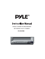
PLTVCP85
CAUTIONS AND WARNINGS
To obtain the best results and to avoid malfunctions, PLEASE READ CAREFULLY
THE DESCRIPTIONS AND OPERATING PROCEDURES CONTAINED IN THIS
OWNER'S MANUAL PRIOR TO OPERATING
THE VIDEO CASSETTE RECORDER.
CAUTION
RISK OF ELECTRIC SHOCKS
DO NOT OPEN
CAUTION TO REDUCE THE RISK OF ELECTRIC SHOCK,
DO NOT REMOVE THE COVER.
NO USER-SERVICEABLE PARTS INSIDE. REFER
SERVICING TO QUALIFIED SERVICE PERSONNEL.
This user manual employs the following symbols to indicate different types of warning
messages.
Indicates the presence of uninsulated dangerous
voltage within the unit enclosure.
Indicates a warning or notice regarding product operation.
Indicates the presence of important operating and
maintenance (servicing) instructions.
WARNING TO PREVENT FIRE OR ELECTRIC SHOCK, DO NOT EXPOSE THIS APPLIANCE
TO RAIN OR MOISTURE.
'
'
AVERTISSEMENT POUR PREVENIR
LES RISQUES D'INCENDIE ET D'ELECTROCUTION,
NE PAS
'
EXPOSER
CET' APPAREIL A' LA PLUIE NI A L'HUMIDITE.
1
SAFETY INSTRUCTIONS
1. Read Instructions-All the safety and operating instructions should be read before the Video
Cassette Recorder is operated.
2. Retain Instructions- The safety and operating instructions should be retained for future reference.
3. Heed Cautions and Warnings-All cautions and warnings regarding the Video Cassette Recorder
should be adhered to.
4. Follow Instructions-All operating instructions should be followed.
5. Cleaning-Unplug or turn off vehicle power to the Video Cassette Recorder before cleaning.
Do not use liquid cleaners or aerosol cleaners. Use only a damp cloth for cleaning.
6. Attachments-Do not use attachments not recommended as they may cause hazards.
7. Water and Moisture-Do not use this video product near water, for example, near a bath tub,
kitchen sink, near a swimming pool or other wet locations.
8. Accessories-Do not place the Video Cassette Recorder on an unstable cart, stand, tripod, bracket,
or table. The Video Cassette Recorder may fall, causing serious injury to a child or adult,
and serious damage to the Video Cassette Recorder. Use only with a cart,stand, tripod, bracket,
or table recommended . When used in vehicles, the Video Cassette Recorder must be securely fastened.
9. Ventilation-Slots and openings in the cabinet are provided for ventilation to ensure reliable operation
of the Video Cassette Recorder and to protect it from overheating. These openings must not be
blocked or covered. The openings should never be blocked by placing the Video Cassette Recorder
on a bed, sofa, rug, or other similar surface. The Video Cassette Recorder should never be placed
near or over a radiator or heat register. This video product should not be placed in a built-in installation
such as a book case or rack unless proper ventilation is provided.
10. Power Sources-The Video Cassette Recorder should be operated only from the type of power
source indicated on the marking label. If you are not sure of the type of power supply ,
consult your appliance dealer or local power company. For video products intended to operate from
battery power or other sources, refer to the operating instructions.
11. Do not attempt to service the set yourself as opening or removing covers may expose you to
dangerous voltage or other hazards.
Refer all servicing to qualified service personnel.
2
INFORMATION TO THE USER
This equipment has been tested and found to comply with the limits for a Class B digital device,
pursuant to part 15 of the FCC Rules. These limits are designed to provide reasonable
protection against harmful interference in a residential installation. This equipment generates,
uses and can radiate radio frequency energy and, if not installed and used in accordance with
the instructions, may cause harmful interference to radio communications. However, there is no
guarantee that interference will not occur in a particular installation. If this equipment does
cause harmful interfere nice to radio or television reception, which can be determined by
turning the equipment off and on, the user is encouraged to try to correct the interference by
one more of the following measures:
- Reorient or relocate the receiving antenna.
- Increase the separation between the equipment and receiver.
- Connect the equipment into an outlet on a circuit different from that to which
the receiver is connected.
- Consult the dealer or an experienced radio/TV technician for help.
WARNING
Changes or modifications not expressly approved by the manufacturer could void the user’s
authority to operate the equipment.
TABLE OF CONTENTS
CAUTIONS AND WARNINGS
SAFETY INSTRUCTIONS
TABLE OF CONTENTS
FEATURES
ACCESSORIES
INSTALLATION WITH MOUNTING BRACKETS
FRONT PANEL-CONTROLS AND INDICATORS
REAR PANEL-CONNECTIONS AND POWER
REMOTE CONTROLLER
SETTING THE MENU
OPERATING TV TUNER
VIDEO HEAD CLEANING
ERASURE PROTECTION
TROUBLE SHOOTING
SPECIFICATIONS
1
2
3
4
4
5
6
8
10
11
13
14
14
15
17
3
FEATURES
BUILT-IN TV TUNER (TV/CATV)
HI-FI STEREO SYSTEM
BACK LIGHTING OF FUNCTION BUTTONS
ON SCREEN DISPLAY (English)
EXTERNAL IR REMOTE CONTROLLER WITH RECEIVER
DEW & HEAT SENSORS FOR TAPE PROTECTION
NTSC COLOR SYSTEM
TWO AUDIO/VIDEO INPUTS
ENCORE FUNCTION
- Press ENCORE key on the remote controller to watch the desired picture once during playback.
AUTO REPEAT PLAY
- This function can be turned on/off from "menu".
DIGITAL AUTO TRACKING
- This VCR plays clear pictures without special operations.
AUTO START FUNCTION
- This VCR will automatically power on and into PLAYBACK mode when a cassette is inserted.
DC POWER SUPPLY (2 KINDS OF DC 12V INPUTS)
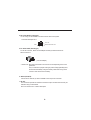
ACCESSORIES
VCR UNIT
INSTRUCTION MANUAL
POWER CABLE
REMOTE CONTROLLER AND BATTERY
REMOTE IR SENSOR CABLE (5M)
CONVERT-ADAPTER
MOUNTING BRACKET AND SCREW
4
INSTALLATION WITH MOUNTING BRACKETS
Use the short screw for the joint of the VCR and bracket.
Use the long screw for installation of this VCR to your vehicle or any
other place.
The VCR can be mounted vertically , horizontally or at any angle in between with the
supplied mounting brackets. The VCR cannot be mounted upside down or on its side.
VCR is sensitive to dirt and other contaminants. Do not mount the unit in direct sunlight
or where fluids are likely to spill on or in the unit.
The VCR is for 12Volt negative ground vehicles only.
5
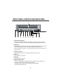
FRONT PANEL-CONTROLS AND INDICATORS
1
REC
DEW
/HEAT
Hi-Fi
13
2
3
4
5
6 7 8 9 10
11
12
1. Cassette Compartment
The power is on automatically when the cassette is inserted even if the power was
off. When the cassette is inserted, Auto Tracking Adjustment operates automatically.
2. Power Key
When power is supplied to the set, the power indicator lamp will always light up in red.
The Power ON and Power OFF mode will be toggled by pressing this key.
When the POWER is switched on, the power lamp will light up in red the other keys will
light up in green.
3. Cassette-In Lamp
When the cassette is inserted, the CST-IN lamp will light up in green.
4. Eject Key
Press this button to eject tape.
5. Stop Key
Press this button to stop tape.
6. Rewind / Review Key
If this key is pressed in the PLAYBACK mode, the VCR enters the reverse picture
search mode, and "REW" indicator lamp will be blinked.
If pressed in STOP mode, then the tape will rewind at high speed,
the indicator lamp will up in red.
6
7. Play / Re-AutoTracking
Press this key to playback a recorded tape, or to release special operation such as the
search mode.
In the playback mode the playback indicator lamp will be light in red, and Auto
Tracking mode, this indicator lamp will blink.
When the playback picture is noisy, press this key to operates Re-Auto Tracking.
8. Fast Forward / Cue Key
If this key is pressed in the PLAYBACK mode, the VCR enters the forward picture search
mode, and "FF" indicator lamp will be blinked.
If pressed in STOP mode, then the tape will fast forward at high speed,
the indicator lamp will up in red.
9. REC Key
Press the REC key for at least one second to start recording.
10. DEW/HEAT Lamp
When power is on, this indicator flashes red to indicate excessive moisture buildup inside
the VCR.
The unit will not operate unit it dries out sufficiently ( the tape can be ejected from the unit).
When DEW mode has been activated, leave the unit on the allow it to dry out completely.
11. Hi-Fi Lamp
In the Hi-Fi out mode, the lamp will light up in red.
12. Auto Repeat Lamp
During Auto repeat operation, Auto Repeat lamp will light up in red.
13. Audio/Video In Jacks (AV2)
Connect these jacks to the audio/video out jacks terminal of your game machine or
camcorder using the RCA cord.
For displaying this Front A/V lnput connected, Input Signal should be set to " AV2" in
Menu setting mode.
7
REAR PANEL-CONNECTIONS AND POWER
6
1 2
7
34 5
1. AUDIO/VIDEO IN (AV1)
Connector this terminal to VIDEO/AUDIO OUT terminal of your Game machine,
Camcorder, Portable DVD Player, using the RCA cord
For displaying this Rear A/V input connected, Input Signal should be set to "AV1"
in Menu setting mode.
2. AUDIO/VIDEO OUT
Connect this terminal to VIDEO/ AUDIO IN terminal of your TV (or Amplifier/Monitor),
using the RCA cord provided.
3. IR INPUT
Connect this terminal to Remote IR Sensor cable provided.
8
4. DC 12V IN JACK (Locking type)
For car using, we recommend to use this connecter with 3-wire system.
* Connector description for 4
ACC 12V
GND
VEHICLE BATTERY 12V
5. DC 12V IN JACK ( Round type)
To use this connector, below Convert-Adapter accessory should be locked into
above connector 4.
( Convert-Adapter)
* Please note : We highly recommend to connect the unit corresponding to the 3-wire
system of 4.
Thus, to make sure a proper working of power-off tape guide. Beyond it,
the unit will automatically change to standby mode after turning off the
vehicle in order to save the car battery.
6. ANT IN (TV/CATV)
Connect the TV antenna (or cable if available- home use) to this connector.
7. RF OUT
This connectors provides an interface to the antenna input connectors terminal of your
television using a coaxial cable.
Set TV to channel 3 or 4 to watch video tapes.
9
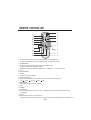
REMOTE CONTROLLER
1. To watch the desired picture once more during playback, press "ENCORE" key .
The VCR unit rewinds the tape for 5 seconds and will play the picture watch again.
2. POWER ON/OFF
3. To watch the picture from start position of tape, press "REPLAY" key .
The VCR unit rewinds the start position of tape.
4. TRACKING -,+ (Manually Tracking in playback mode) / CHANNEL -,+ ( in TV or CATV mode)
5. PLAY
6. FAST FORWARD
7. SELECT
8. Tape speed in recording (SP,EP)
9. SHIFT (Cursor Move)
10. During the Hi-Fi STEREO tape playback mode, you can select the audio out channel.
"Hi-Fi
Hi-Fi "L"
Hi-Fi "R"
Mono
Hi-Fi
"
11. RECORDING
12. MENU (setting OSD, System and TV Tuner)
13. STOP
14. REWIND
15. PAUSE/STILL
16. When the playback picture is noisy, this "RE - TRACKING" key will control the playback picture quality
automatically.
17. EJECT
18. Press to switch between TV and VCR source.
This switch is functioned only when RF OUT connects to TV antenna Input with setting of the TV channel 3 or 4.
10
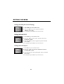
SETTING THE MENU
Setting the OSD (On Screen Display)
MENU
OSD
AUTO PLAY
AUTO REPEAT
RECORD SPEED
VCR OUTPUT CH
INPUT SIGNAL
SHIFT:
SEL:
ON
ON
ON
EP
CH3
TV
END:MENU
1. Press MENU key on the remote control.
2. Press select
key until the appropriate system is
selected. ( "on" or "off" )
3. On completion, press MENU key to exit the menu.
Setting the Auto PLAY
MENU
OSD
AUTO PLAY
AUTO REPEAT
RECORD SPEED
VCR OUTPUT CH
INPUT SIGNAL
SHIFT:
SEL:
ON
ON
ON
EP
CH3
CATV
END:MENU
1. Press MENU key on the remote control.
2. Press shift
key, until the cursor is placed in front of the
"AUTO PLAY " option.
3. Press select
key until the appropriate system is selected.
( "on" or "off" )
4. On completion, press MENU key to exit the menu.
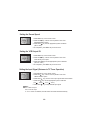
Setting the Auto Repeat
MENU
OSD
AUTO PLAY
AUTO REPEAT
RECORD SPEED
VCR OUTPUT CH
INPUT SIGNAL
SHIFT:
SEL:
ON
ON
ON
EP
CH3
CATV
END:MENU
1. Press MENU key on the remote control.
2. Press shift
key, until the cursor is placed in front of the
"AUTO REPEAT " option.
3. Press select
key until the appropriate system is selected.
("on" or "off ")
4. On completion, press MENU key to exit the menu.
11
Setting the Record Speed
MENU
OSD
AUTO PLAY
AUTO REPEAT
RECORD SPEED
VCR OUTPUT CH
INPUT SIGNAL
SHIFT:
SEL:
ON
ON
ON
EP
CH3
TV
END:MENU
1. Press MENU key on the remote control.
2. Press shift
key, until the cursor is placed in front of the
"RECORD SPEED" option.
3. Press select key until the appropriate system is selected.
("EP" or "SP")
3. On completion, press MENU key to exit the menu.
Setting the VCR Output CH
MENU
OSD
AUTO PLAY
AUTO REPEAT
RECORD SPEED
VCR OUTPUT CH
INPUT SIGNAL
SHIFT:
SEL:
ON
ON
ON
EP
CH3
TV
END:MENU
1. Press MENU key on the remote control.
2. Press shift
key, until the cursor is placed in front of the
"VCR OUTPUT CH" option.
3. Press select
key until the appropriate system is selected.
("CH3" or "CH4")
3. On completion, press MENU key to exit the menu.
Setting the Input Signal (Entrance to TV Tuner Operation)
MENU
OSD
AUTO PLAY
AUTO REPEAT
RECORD SPEED
VCR OUTPUT CH
INPUT SIGNAL
SHIFT:
SEL:
ON
ON
ON
EP
CH3
TV
END:MENU
1. Press MENU key on the remote control.
2. Press shift
key, until the cursor is placed in front of the
"INPUT SIGNAL" option.
3. Press select
key, then the current input signal mode will be blinked.
4. Press shift
key until the appropriate system is selected.
("TV"
"CATV"
"AV1"
"AV2" )
5. Press select key, to keep selected input signal.
Note :
AV1 - Rear A/V Input
AV2 - Front A/V Input
If " TV" or "CATV" is selected, channels will be found and stored automatically.
12
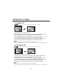
OPERATING TV TUNER
TV CHANNEL SET
If RF-Signal is not input searching channel will be displayed blue-back picture.
MENU
OSD
AUTO PLAY
AUTO REPEAT
RECORD SPEED
VCR OUTPUT CH
INPUT SIGNAL
SHIFT:
SEL:
ON
ON
ON
EP
CH3
TV
CH***
AUTO
SEARCHING..........
END:MENU
1. Press MENU key on the remote control.
2. Press shift
key, until the cursor is placed in front of the "INPUT SIGNAL" option.
3. Press select
key, then the current input signal mode will be blinked.
4. Press shift
key, until "TV" is selected.("TV"
"CATV"
"AV1"
"AV2)
5. Press select key, then channels will be found and stored automatically.
While the "AUTO SEARCHING " is progressing, channels will be changed up to 69.
6. When searching and storing is completed, the TV mode will be displayed.
NOTE :
While searching and storing channels, no button will be operated.
When "AUTO REPAT" function is "OFF" and VCR is "STOP" mode, this function will be operated.
CATV CHANNEL SET
If RF-Signal is not input searching channel will be displayed blue-back picture.
MENU
OSD
AUTO PLAY
AUTO REPEAT
RECORD SPEED
VCR OUTPUT CH
INPUT SIGNAL
SHIFT:
SEL:
ON
ON
ON
EP
CH3
CATV
CH***
AUTO
SEARCHING..........
END:MENU
1. Press MENU key on the remote control.
2. Press shift key, until the cursor is placed in front of the "INPUT SIGNAL" option.
3. Press select
key, then the current input signal mode will be blinked.
4. Press shift key, until "CATV" is selected.("TV"
"CATV"
"AV1"
"AV2)
5. Press select key, then channels will be found and stored automatically.
While the "AUTO SEARCHING " is progressing, channels will be changed up to 125.
6. When searching and storing is completed, the CATV mode will be displayed.
NOTE :
While searching and storing channels, no button will be operated.
When "AUTO REPAT" function is "OFF" and VCR is "STOP" mode, this function will be operated.
13
VIDEO HEAD CLEANING
The video heads enable the VCR to read video information pictures from the tape during playback.
In the unlikely event that the heads become clogged with dirt video playback will be impossible.
This can easily be determined during playback of a known good tape, there is good sound, but the
picture is extremely snowy.
If this is the case, have the video cassette recorder checked by qualified service personnel.
NOTES
During normal operation of the VCR, the video and audio heads can accumulate dirt over a period
of time, especially when using an old or poor quality tape. When the heads are dirty, the picture
can get snowy and the tracking control will have little or no effect.
If this condition occurs, head cleaning cartridges may take care of the problem and restore normal
picture.
We recommend that head cleaning cartridges be used sparingly since they are very abrasive and
can damage the video heads during prolonged use.
If the problem is not resolved with the head cleaning cartridge then the unit needs to be checked
by a qualified service personnel.
ERASURE PROTECTION
Video cassettes are equipped with a safety tab to prevent accidental erasure. When the tab is
removed, recording can not be performed.
TO PREVENT ACCIDENTAL ERASURE
- After recording, break off the safety tab with a screwdriver
if you don't want to record over the tape.
TO RECORD AGAIN
- Cover the hold with cellophane tape.
14
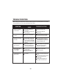
TROUBLE SHOOTING
Before calling service personnel, check the following points for a possible cause of the trouble.
A minor adjustment on your part may eliminate the trouble.
SYMPTOMS
CAUSE
POSSIBLE SOLUTIONS
The power cord is not
connected.
The polarity of power cord
is not correct.
Check the power cord.
Noise bars on
screen.
Tracking is not adjusted.
Adjust the picture to be clear
by pressing the Re-tracking.
Operation key does
not work.
If the cassette or the VCR
is not in normal condition,
every indicator LED/LAMP
lights up and the VCR does
not work.
Turn off the power and turn on
the power again by pressing
the POWER cord. Unplug and
replug the power cord.
Cassette is ejected
upon inserting
Safety device works to
protect the cassette when
it is inserted incorrectly.
Pull the cassette out (unloading)
and insert it firmly into the
cassette compartment.
Audio output does
not change to
Hi-Fi mode.
The cassette is recorded
in mono VCR.
The first auto tracking is
executing unit now.
The cassette can not be
playback in Hi-Fi mode.
Wait for a second.
No backlighting at
power button.
No 12V DC.
Check circuit fuse at source of
power
(see vehicle/converter manual).
In-line fuse of power cord
(in light plug).
Power cord unplugged from
12V outlet or at rear of unit.
There is no power
to the VCR?
15
Change the polarity of
power cord.
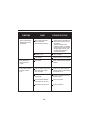
SYMPTOMS
CAUSE
POSSIBLE SOLUTIONS
(Unit in dew mode) Dew
feature activated
(see instruction manual)
Retain power to recorder and
allow unit for a time to get rid
of moisture.
(After 30 minutes if dew
indicator is still on, completely
switch power off from unit and
resupply after a minute. This
can reset dew indicator if
moisture eliminated.)
No tape in unit.
Insert the tape.
Low voltage.
Start the vehicle, if not running.
Poor video/snow
picture or line on
screen.
Dirty heads.
Clean head using tape cartride
cleaner.
PLAY mode indicated
no audio or video
to TV.
VCR connected to A/V Input
jack, RCA patch cables
set in TV mode.
Switch TV to video mode with
remote control or switch behind
control door of TV.
VCR connected to A/V
output jacks.
Change connections from A/V
out to A/V input.
Poor connection between
VCR output and TV input.
Check connection.
Reversed A/V inputs to TV.
Check connection.
Power indicated with
backlighting-unit will
not operate.
16
SPECIFICATIONS
MODEL
PLTVCP85
POWER SUPPLY
DC 12V
POWER CONSUMPTION
13W
DIMENSION
265 X 91 X 275 (W xH x D)mm
WEIGHT APPROX
2.9Kg
VIDEO SIGNAL SYSTEM
NTSC color
TAPE TYPE
VHS Type
TAPE SPEED
SP: 33.35 mm/sec,
LP: 22.23mm/sec, SLP: 11.12 mm/sec
Antenna In/Output terminnals
UHF/VHF 75
F type connector.
FF/REW TIME(T-120)
Approx. 5min
VIDEO SIGNAL INPUT
Video In terminal (RCA) 1.0 Vp - p
AUDIO SIGNAL INTPUT
Audio In terminal (RCA),47K ohm
VIDEO SIGNAL OUTPUT (LINE)
1.0Vp-p, 75 ohm unbalanced, NEGATIVE SYNC
AUDIO SIGNAL OUTPUT(LINE)
-6dBm
OPERATING CONDITION HUMIDITY
80 RH (MAX).
Temperature : 5
OPERATING POWER VOLTAGE
~ 35
12 ~ 14V
Desing and specifications are subjected to change without notice.
17
(41
~ 95
)