1
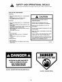
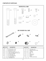
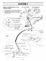
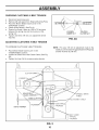
Agri-Fab ®
OWNERS
MANUAL
Model No.
45-03051
63" FINISH CUT
TRAILMOWER
CAUTION"
Read Rules for
Safe Operation
and Instructions
Carefully
•7_l_UM_rdri
PRINTED
_N
U.S.A.
NOTE: Your mower deck will require a 12 volt battery to operate. This
battery is NOT included with the deck but must be purchased separately.
Any 12 volt tractor battery with about 230 cold cranking amps. will
operate the machine.
•
•
•
•
Assembly
Operation
Maintenance
Parts
the fastest way topurchase parts
www.speedepart.corn
FORM
NO.
48799/2/04/
TABLE OF CONTENTS
SAFETY RULES ............................................
3-4
SAFETY AND OPERATION DECALS .......... 5-6
PARTS BAG CONTENTS ................................. 7
ASSEMBLY .................................................
8-11
OPERATION ..............................................
12-17
CUSTOMER RESPONSIBILITIES ............ 18-21
STORAGE .......................................................
22
WIRING DIAGRAM .......................................... 23
REPAIR PARTS ........................................
24-30
PARTS ORDERING ....................... BACK PAGE
2
SAFETY
RULES
Safe Operation Practices for Tow Behind Mowers
IMPORTANT: THIS CUTTING MACHINE IS CAPABLE OF AMPUTATING HANDS AND FEET AND THROWING
OBJECTS. FAILURE TO OBSERVE THE FOLLOWING SAFETY INSTRUCTIONS COULD RESULT IN SERIOUS
INJURY OR DEATH.
|,
•
•
o
•
•
•
•
•
•
•
•
e
•
•
•
•
•
GENERAL OPERATION
II.
Read, understand, and follow all instructions in the manual and on
the machine before starting.
Reed this operator's manual carefully. Become familiar with the
controls and know how to operate your mower properly.
Only allow responsible adults, who are familiar with the instructions,
to operate the machine.
Clear the area of objects such as rocks, toys, wire, etc., which
could be picked up and thrown by the blade.
Be sure the area is clear of other people before mowing. Stop
machine if anyone enters the area.
Never carry passengers.
Do not mow in reverse unless absolutely necessary. Always lock
down and behind before and while becking.
Be aware of the mower discharge direction and do not point it at
anyone. Do not operate the mower without the guard in place.
Slow down before turning.
Never leave a running machine unattended. Always turn off blades,
and stop engine.
Turn off blades when not mowing.
Mow only in daylight or good artificial light.
Do not operate the machine while under the influence of alcohol or
drugs.
Watch for traffic when operating near or crossing roadways.
Usa extra care when loading or unloading the machine into a trailer
or truck.
SLOPE OPERATION
Slopes are a major factor related to loss-of-control and tipover accidents,
which can result in severe injury or death. All slopes require extra
caution. If you feel uneasy on it, do not mow it.
DO:
•
Remove obstacles such as rocks, tree limbs, etc.
•
Watch for holes, ruts, or bumps. Uneven terrain could overturn the
machine. Tall grass can hide obstacles.
•
Use slow speed. Choose a low gear so that you will not have to
stop or shift while on the slope.
Follow the manufacturer's recommendations for wheel weights or
counterweights to improve stability.
•
•
Keep all movement on the slopes slow and gradual. Do not make
sudden changes in speed or dirsction,
•
Avoid starting or stopping on a slope. If tires lose traction,
disengage the blades and proceed slowly straight down the slope.
DO
NOT:
•
Do not turn on slopes unless necessary, and then, turn slowly and
gradually downhill, if possible.
•
Do not mow near drop-offs, ditches, or embankments. The mower
could suddenly turn over if a wheel is over the edge of a cliff or
ditch, or if an edge caves in.
•
Do not mow on wet grass. Reduced traction could cause sliding.
Do not attempt to operate your tractor or mower when not in drivers
seat.
Disengage power to mower, stop engine when transporting or not in
Mow up and down slopes, not across.
•
Use.
•
•
•
•
.
•
•
•
•
•
•
Exercise special cars when mowing around fixed objects in order to
prevent the blades from striking them. Never deliberately run
tractor or mower onto or over any foreign object.
Use mower only as the manufacturer intended and as described in
this manual.
III.
CHILDREN
Tragic accidents can occur if the operator is not alert to the presence of
children. Children are often attracted to the machine and the mowing
activity. Never assume that children will remain where you last saw
them.
Do not operate mower if it has been dropped or damaged in any
manner. Always have damage repaired before using your mower.
Always wear safety glasses or eye shields when starting and while
using your mower.
Dress properly. Do not operate mower when barsfcot or wearing
open sandals. Wear only solid shoes with good traction when
mowing.
Always make cutting height adjustments before starting your
mower. Never attempt to do this while the engine is running.
Keep your eyes and mind on your mower and the area being cut.
Do not let other interests distract you.
Do not put hands or feet near or under rotating parts. Keep clear of
the discharge opening at all times.
Before cleaning, inspecting, or repairing your mower, stop the
engine and make absolutely sure the blade and all moving parts
have stopped. Then disconnect the spark plug wire and keep it
away from the spark plug to prevent accidental starting..
Do not operate your mower if it vibrates abnormally. Excessive
vibration is an indication of damage; stop the engine, safely check
for the cause of vibration and repair as required.
Never operate your mower without proper guards, plates, or other
safety devices in place.
•
3
•
Keep children out of the mowing area and under the watchful care
of another responsible adult.
Be alert and turn machine off if children enter the area.
•
Before and when backing, look behind and down for small children.
•
Never carry children. They may fall off and be seriously injuredor
interfere with safe machine operation,
•
Never allow children to operate the machine.
•
Use extra care when approaching blind corners, shrubs, trees, or
other objects that may obscure vision.
IV.
•
•
SERVICE
Use extra care in handling gasoline and other fuels. They are
flammable and vapors are explosive.
Use only an approved container.
-Never remove gas cap or add fuel with the engine running,
Allow engine to cool before refueling. Do not smoke.
-Never refuel the machine indoors.
-Never store the machine or fuel container inside where there
is an open flame, such as a water heater.
Never run a machine inside a closed area.
•
Keep nuts and belts, especially blade attachment nuts, tight and
keep equipment in good condition.
•
Never tamper with safety devices. Check their proper operation
regulady.
•
Keep machine free of grass, leaves, or other debris build-up. Clean
oil or fuel spillage. Allow machine to cool before storing.
•
Stop and inspect the equipment if you strike an object. Repair, if
necessary, before restarting.
•
Never make adjustments or repairs with the engine running.
•
Mower blades are sharp and can cut. Wrap the blade(s) or wear
gloves, and usa extra caution when servicing thom.
•
Check brake operation frequently. Adjust and service as required.
Look for this symbol to point out
important safety precautions. It
means CAUTIONI!!
BECOME
ALERTII! YOUR SAFETY IS
INVOLVED.
CAUTION: Always disconnect spark
plug wire and place wire where it
cannot contact spark plug in order
to prevent accidental starting when
setting up, transporting, adjusting
or making repairs.
4
SAFETY AND OPERATIONAL
Replace
decal immediately
if damaged.
Order
DECALS
by part number.
See back cover.
HOW TO USE YOUR MOWER
STOPPING
• Move mower blade clutchlever to "DISENGAGED"
position.
• Move throttle control to "SLOW" position.
• Turn ignition key to "OFF" position.
CAUTION
• READ AND FOLLOW DIRECTIONS IN
OWNERS MANUAL
STARTING
• Move mower blade clutch lever to "DISENGAGED"
position.
• Move throttle control to the choke position for cold
engine starts.
• Turn ignition key clockwise to "START' position and
release key as soon as engine starts.
• When engine starts, slowly move throttle control to
"FAST" position.
• Allow engine to warm up.
• KNOW HOW TO OPERATE BOTH THE
VEHICLE AND THE MOWER ATTACHMENT
• NEVER ALLOW
EQUIPMENT
CHILDREN
• DO NOT LEAVE
UNATTENDED
MOWER
TO USE THE
RUNNING
WITH
UNIT
• KEEP ALL SAFETY FEATURES IN PLACE AND
OPERATING
USE
• Sit on tractor seat.
• Move mower blade clutch lever to "ENGAGED"
position.
• Operate tractor at medium ground speed.
(3-4 MPH)
• AVOID CONTACT WITH MOVING PART. KEEP
HANDS AND FEET AWAY FROM BLADES
STOP ENGINE BEFORE FUELING,ADJUSTING
OR INSPECTING. DO NOT ADD FUEL TO AN
ENGINE THAT IS RUNNING OR HOT
TRANSPORTING
• Shut off engine.
• Place mower deck in the highest position directly
behind tractor.
HA24431
DANGER
ROTATING
BLADES AND
BELTS.
KEEP ALL SHIELDS IN PLACE.
KEEP HANDS AND FEET
FROM UNDER MOWER.
HA12314
DANGER ROTATING BLADES DECAL
HA12315
5
DANGER DECAL
SAFETY AND OPERATIONAL
DECALS
Replace decal immediately if damaged. Order by part number. See back cover.
S
BLADES
ENGAGED
BLADES
DISENGAGED
BLADE CLUTCH LEVER
HA23265
CLUTCH
LEVER
OPERATION
DECAL
THRO_LE
_
CHOKE
SLOW
HA23820
J
CUTTING
TOW
HITCH
OFFSET
•
ADJUSTMENTS
TO
TO obtain
the best
measure
from the bottm edge of the deck
ground at both front and rear of the deck.
to the
TO
BACK
•
•
•
Remove the locating
adjustment
strap.
•
We recommend
when cutting
with a tow
vehicle
all ready equipped
with a 46", or 50"
mower that the 49" offset be used, When
Move height adjustment
align it with the desired
adjustment
strap
•
cutting
with a tow vehicle all ready equipped
with a 36", 38", 40" or 42" mower, the 36" offset
•
Reassembte
tocating pin to the height of
adjustment strap and secure with hair cotter
pin.
Make sure that both side height adjustment
STRAIGHT
The adjustable
tow hitch of this mower can be
set in four positions,
straight,
approximately
20" offset,
36" offset,
and 49" offset to either
side.
straps
be used, When cuffing heavier grass or when
conditions
warrant the mower can be adjusted
to the 20" offset position.
If tow vehicle is not equipped
with a mid
20" OFFSET
are adiusted
pin from
the height
strap up or down to
hole in the height
to the same
height,
BACK
RAKE
cutting
ADJUSTMENT
results
and
reduce
engine _oad, the mower
housing
sbou_d be adjusted
so that the front is approximately
1/2 to 1" lower
than the rear, To check front to back adjustment,
•
•
•
•
ADJUST
MOWER
FROM
FRONT
TO
Remove
two hair cotter pins from two clevis
pins in the tow bar a_djustment
Remove
two clevis pins from tow bar adjustment
Raise or lower the tow bar to obtain the proper
front to back adjustment.
Reassemble
two clevis pins to tow bar
adjustment
and secure
with two hair
cotter
pir_s.
mount mower
the hitch can be adjusted
to a
straight position,
but we recommend
using the
offset position
to eliminate
grass being
LATCH
LATCH
HEIGHT
This tow behind mower
has been designed
to run
offset from the center of the tow vehicle to give
additional
cutting width,
•
49" OFFSET
FRONT
To adjust the mower cutting height remove
hair cotter pin from IDeating pin
Apply lift pressure to height adiustment
lift lever,
ADJUSTMENT
49" OFFSET
crushed
down
by the tow vehicle,
FRONTQUADRANT
TO
ADJUST
THE
•
Pull back
the pivot
OFFSET
latch
front quadrant.
Adlust the
desired offset and release
the notch of the quadrant.
•
REAR QUADRANT
HITCH
from
the notch
TOW BAR
ADJUSTMENT
of the
hitch tube to the
the pivot latch into
Pull back the pivot latch from the notch of the
rear quadrant.
Adjust the hitch tube to the
corresponding
notch of the front quadrant
and
release
the
pivot
latch
IMPORTANT:
The hgch tube
assembled
to the same offset
into the
LOCATING
notch,
must be
notch }n both
TOWBAR
the
T_
front and
rear quadrants.
LIFT
LEVER
HEIGHT
STRAP
HA23812
6
CUTTtNG
MOWER
HEIGHT
BLADE
ADJUSTMENT
\
GROUND
LEVEL
CONTENTS
OF PARTS BAG
SHOWN
FULL SIZE
jF
_jH
NOT SHOWN
FULL SIZE
jS
-_
KEY
QTY.
A
B
C
D
E
F
G
H
I
J
1
1
3
2
3
2
1
2
2
2
DESCRIPTION
Bolt, Hex 3/8" x 2-3/4"
Bolt, Hex 3/8" x 2-1/2"
Bolt, Hex 1/4" x 3/4"
Screw, Pan Head #10-24 x 1/2"
Screw, Self Tapping #10-16 x 1/2"
Nut, Hex Lock 3/8"
Nut, Hex Lock 1/4"
Nut, Hex with Washer
Nut, Hex #10-24
Lock Washer, #10
7
KEY
QTY.
K
L
M
N
0
P
Q
R
S
2
1
2
6
1
1
1
1
1
j
DESCRIPTION
Flat Washer, 3/8"
Battery Hold Down Strap
"S" Hook
Cable Clip
Key
Switch Cover
Switch Nut
Switch
Throttle Control Knob
ASSEMBLY
REMOVING
UNIT FROM CRATE
•
•
Remove top boards.
Cut wire tie&
•
•
Remove Hitch Assembly.
Remove front of crate.
•
Roll mower forward out of crate.
INSTALL WIRE HARNESS, THROTTLE
CABLE AND CLUTCH CABLE TO TOW BAR
•
•
•
CAUTION
Before starting to assemble mower,
remove spark plug wire from plug of
mower engine.
OPERATOR
•
•
ORIENTATION
•
When right and left are mentioned in this manual, it
means when you are in the operating position (seated
behind the steering wheel).
•
•
CONTENTS
OF CRATE
•
Mower Deck
•
Tow Bar Hitch
•
Owner's Manual
•
Parts Bag (Found inside Battery Box.)
•
Your Mower Deck will require a 12 volt battery to
operate. This battery is NOT included with the deck
but must be purchased separately. Any 12 volt
tractor battery with about 230 cold cranking amps
will operate the machine.
•
•
OIL
•
•
Very Important:
Engine must be filled with oil before operation. See Oil
& Fuel Recommendations in Engine Owner's Manual for
correct filling instructions and oil fill capacity.
•
INSTALL TOW BAR HITCH TO REAR
QUADRANT
•
Lay the Throttle Cable along the left side of the Tow
Bar Tube.
Assemble three 1/2 inch Cable Clips on to Throttle
Cable
Lay the Clutch Cable along the left side of the Tow
Bar Tube.
Insert the Clutch Cable into the two 1/2 inch Cable
Clips toward the hitch with the Throttle Cable.
Place 1/2 inch Cable Clips of one side on top of 1/2
inch Cable Clips on other side.
Align holes of Cable Clips with three holes in Tow
Bar Tube and secure with three #10 Self-Tapping
Screws.
Keep all three cables on top of Tow Bar Tube and
tuck Clutch Cable through slot at bottom of Control
Panel.
INSTALL
LEVER
•
ENGINE
Cut plastic tie then remove Wire Harness, Throttle
Cable and Clutch Cable from bag and from around
engine. (See Fig. 1)
Lay Wire Harness along the right side of the Tow
Bar Tube.
Assemble three 1/2 inch Cable Clips onto wire
Harness.
•
CLUTCH
CABLE
TO CLUTCH
Remove outer 5/16 Nut from end of Clutch Cable
Housing. (See Fig. 1)
Turn inner 5!16 Nut to bottom of thread.
insert Cable and outer 5/16 Nut through slotted hole
in Cable Guide of Hitch Assembly. The outer 5/16
Nut must be cocked sideways to insert through
slotted hole of Cable Guide.
Reinstall outer 5/16 Nut to the cable housing to
secure Cable Harness to Cable Guide.
Install Mounting Anchor of Clutch Cable to Clutch
Lever using 1/4-20 x 3/4 Hex Bolt and 1/4-20 Lock
Nut. Tighten 1/4-20 Lock Nut securely and then
loosen approximately two turns to allow Mounting
Anchor to pivot freely on bolt.
Slide tube of Tow Bar Hitch into rear quadrant and
align holes. (See Fig. !)
Insert a 3/8 x 2 3/4 Hex Bolt through rear hole of
quadrant and tube.
Secure Bolt, hand tighten only with a 3/8 Lock Nut.
Assemble 3/8 Flat Washer onto 3/8 x 2 3/4 Bolt.
INSTALL THROTTLE CONTROL
TO THE CONTROL PANEL.
•
Insert the Bolt through quadrant slot, through Tow
Bar Tube and slot in Lower Plate.
•
•
Secure Bolt, hand tighten only with one 3/8 Flat
Washer and 3/8 Lock Nut.
Tighten Lock Nuts down tight on both Bolts.
Back Nut off 1/4 turn to allow Tube to pivot freely.
Tow Bar Tube must pivot freely when latch is pulled
from notch in rear quadrant.
•
•
•
•
•
•
•
•
8
HANDLE
Place Throttle Control Handle inside Control Panel
with the handle through the slot on the left side.
Secure the Throttle Control Handle with two #10 x
1/2 Pan Head Screws, two #10 Lock Washers and
two #10 Nuts.
Assemble Throttle Control Knob onto top of Handle
and push down on it to secure
ASSEMBLY
INSTALL STARTER
CONTROL PANEL
•
•
•
SWITCH
3/8 X 2-1/2 HEX BOLT
TO THE
3/8 X 2-3/4 HEX BOLT
Install Connector of Wire Harness to Starter Switch.
Insert Starter Switch into hole of Control Panel.
Secure Starter Switch with Switch Nut (plastic)
and Rubber Cover.
#10
_I"
1/2 INCH CABLE CLIPS
HARNESS
3/8 LOCK
CABLE
CABLE
(TWO FRONT
CLIPS ONLY)
t
' 114 X 3/4
HITCH
MOUNTING
ANCHOF
/
CLUTCH
FIG. 1
CABLE GUIDE
/
INNER 5116 NL
/
OUTER
MOWER
CONTROL
PAN
UT(PLASTIC)
/
RUBBER COVER
LOCK NUT
X
STARTER
SWITCH
"" _
"_'_#10
_ _
_
\
#10 LOCK WASHER .-.
PAN HEAD SCREW
_ I-
-IROTTLE
HANDLE
THROTTLE
CONTROL_
9
NUT
/
CONTROL
,
ASSEMBLY
CHECKING
•
•
•
•
•
•
CLUTCHING
Disconnect spark plug wire.
Remove left side panel from Engine Mounting Plate.
Place the Mower Blade Clutch Lever in the
"ENGAGED" position.
Check spring tension. (See Fig. 2)
Tension is correct if there is a 5/8 to 7/8 inch gap
between the spring clip and the trunnion of the
spring rod.
If gap is not 5/8 to 7/8 inch, an adjustment will be
required.
ADJUSTING
CLUTCHING
TO INCREASE CLUTCHING
•
•
•
V-BELT TENSION
V-BELT
==..__
____-_
...._ _:p___-.-.%
_._---
_
--
i _IK,=---_
LOOSEN
INNER NUT
!
,
t
'
TIGHTEN
OUTER NUT
FIG. 2A
TENSION
V-BELT TENStON:
NOTE: For every 1/8 inch of adjustment made to the
Cable you will increase the gap between the Ring Clip
and the Trunnion by 1/8 inch.
Place Mower Blade Clutch Lever in the
"DISENGAGED"
position.
Loosen the Outer Nut of the Clutch Cable. (See Fig.
2A)
Tighten the Inner Nut to increase spring tension.
CLUTCH
/
INDLE DRIVE
V-BELT
V-BELT
1/16" TYPICAL
4 PLACES
BELT GUIDE
TYPICAL
4 PLACES
FIG. 2
10
ASSEMBLY
ASSEMBLE
•
•
•
•
•
•
•
BATTERY
TO THE MOWER
Remove Battery Box Cover by removing four SelfTapping Screws. (See Fig. 3)
Remove paper backing from Battery Pad and install
to Engine Mounting Plate centered between "S"
hook slots.
Assemble two "S" Hooks to the rubber Battery Hold
Down Strap.
Assemble"S" Hook of Battery Hold Down Strap into
far side slot of Engine Mounting Plate
Place Battery onto Battery Pad.
Loop Battery Hold Down Strap over the top of the
Battery and secure into slot and hole on the outside
of the Battery.
Assemble red Battery Cable to the positive side of
the Battery and secure with one 1/4 x 3/4 Hex Bolt
and one 1/4 Nut with Washer
•
Assemble Black Battery Cable to the negative side
of the Battery and secure with one 1/4 x 3/4 Hex
Bolt and one 1/4 Nut with Washer
•
Reassemble Battery Box Cover and secure with four
Self-Tapping Screws.
/
BLACK BATTERY CABLE
NEGATIVE SIDE (-)
BATTERY BOX COVER
RED BATTERY CABLE
POSITIVE SIDE (+)
1/4 X 3/4 HEX BOLT
NUT
1/4 X 3/4
1/4 NUT
SELF-TAPPING
RY
BATTERY HOLD
DOWN STRAP
ENGINE MOUNTING
PLATE
FIG. 3
11
BATTERY PAD
SCREW
OPERATION
KNOW YOUR MOWER
READ THIS OWNER'S MANUAL AND SAFETY RULES BEFORE OPERATING YOUR MOWER.
Compare the illustrations with your mower to familiarize yourself with the location of various controls and adjustments.
Save the manual for future reference.
HEIGHT ADJUSTMENT
LIFT LEVER
HEIGHT ADJUSTMENT
STRAP
\
\
\
TOW HITCH OFFSET
ADJUSTMENT
HEIGHT ADJUSTMENT
STRAP
HEIGHT ADJUSTMENT
LIFT LEVER
IGNITION
SWITCH
MOWER BLADE
CLUTCH LEVER
'THROTTLE CONT_ROL
TOW BAR HEIGHT ADJUSTMENT
FIG. 4
HEIGHT ADJUSTMENT STRAP - Controls cutting
height.
TOW BAR HEIGHT ADJUSTMENT - To level mower
front to rear.
TOW HITCH OFFSET ADJUSTMENT - To adjust
mower deck offset from tractor center.
MOWER BLADE CLUTCH LEVER - Starts and stops
mower blade rotation.
THROTTLE CONTROL - Controls engine speed, engine
shut-off and engine choke.
IGNITION KEY SWITCH - Used to start and stop
engine.
HEIGHT ADJUSTMENT LIFT LEVER - Raise and lower
mower to different cutting heights.
12
OPERATION
The operation of any mower can result in foreign objects being thrown into the eyes,
which can result in severe eye damage. Always wear safety glasses or eye shields
before starting your mower and while mowing. We recommend wide vision safety mask
for over the spectacles or standard safety glasses.
CHILDREN
,_
Tragic accidents can occur if the operator is not alert to the presence of children.
Children are often attracted to the machine and the mowing activity. Never
assume that children will remain where you last saw them.
HOW TO USE YOUR
ATTACHING
MOWER
STOPPING
•
MOWER BLADES-
•
•
Move mower blade clutch switch to "DISENGAGED"
position.
•
ENGINE•
•
MOWER
TO TRACTOR
Place mower behind tractor and back tractor up to it
for attaching. (See Fig. 5)
Slide tow bar of mower over tractor draw bar so that
the hitch pin holes line up.
Insert hitch pin until it extends through the bottom of
the tow bar.
Insert hair cotter pin through hitch pin.
Move throttle control to "SLOW" position.
NOTE: Failure to move throttle control to "SLOW"
position or allowing engine to idle before stopping may
cause engine to "backfire".
•
Turn ignition key to "OFF" position and remove key.
Always remove key when leaving tractor to prevent
unauthorized use.
•
Never use choke to stop engine.
TO USE CHOKE
CONTROL
TRACTOR"
HITCH PIN
OR MOWER
CLEVIS PIN
Use choke control whenever you are starting a cold
engine. Do not use to start a warm engine.
•
•
•
To engage choke control, move throttle control to
choke position.
After engine has started move throttle control to full
throttle position.
TO USE THROTTLE
HAIR COTTER PIN
FIG. 5
CONTROL
Always operate engine at full throttle,
•
•
Operating engine at less than full throttle reduces
the battery charging rate.
Full throttle offers the best mower performance.
TRANSPORTING
•
•
TRACTOR
DRAWBAR
Shut off engine.
Place mower deck in the highest position directly
behind tractor.
13
OPERATION
ADD GASOLINE
TO START
Fill fuel tank. Use fresh, clean, regular unleaded
gasoline. (Use of leaded gasoline will increase
carbon and lead oxide deposits and reduce
valve life.
IMPORTANT:
WHEN OPERATING
When starting engine for the first time or if engine has
run out of fuel, it will take extra cranking time to move
fuel from the tank to the engine.
•
IN
•
TEMPERATURES BELOW 32°F(0°C), USE FRESH,,
CLEAN WINTER GRADE GASOLINE TO HELP
INSURE GOOD COLD WEATHER STARTING.
•
WARNING: Experience indicates that alcohol blended
fuels (called gasohol or using ethanol or methanol) can
attract moisture which leads to separation and formation
of acids during storage. Acidic gas can damage the fuel
system of an engine while in storage. To avoid engine
problems, the fuel system should be emptied before
storage of 30 days or longer. Drain the gas tank, start
the engine and let it run until the fuel lines and
carburetor are empty. Use fresh fuel next season. See
Storage Instructions for additional information. Never
use engine or carburetor cleaner products in the fuel
tank or permanent damage a may occur.
BEFORE
STARTING
•
•
Fill engine with oil. (See engine manual for proper
procedure and requirements.
•
Add gasoline. Fill fuel tank using fresh clean
unleaded gasoline. (See tractor manual for safe
filling procedure and storage instructions)
Move mower blade clutch lever to"DISENGAGED"
position.
Move throttle control to the choke position for cold
engine starts. For warm engine starts move throttle
control to midway between "FAST" and "SLOW"
positions.
Turn ignition key clockwise to "START" position and
release key as soon as engine starts. Do not run
starter continuously for more than fifteen seconds
per minute. If engine does not start after several
attempts, move throttle control to "FAST" position,
wait a few minutes and try again.
When engine starts, slowly move throttle control to
"FAST" position.
Allow engine to warm up for a few minutes before
engaging mower blade clutch lever.
NOTE: If at a high altitude (above 3000 feet) or in cold
temperatures (below 32°F), the carburetor fuel mixture
may need to be adjusted for best engine performance.
See "TO ADJUST CARBURETOR"
in your Engine
Owner's Manual
ENGINE
•
ENGINE
CAUTION:
CHECK AREA UNDER AND
AROUND MOWER FOR ANY OBJECTS
THAT COULD BE THROWN FROM
UNDER MOWER. MAKE SURE THAT
MOWER DISCHARGE AREA IS CLEAR.
CAUTION:
FILL TO BOTTOM OF FUEL TANK FILLER
NECK. DO NOT OVERFILL. WIPE OFF
ANY SPILLED OIL OR FUEL. DO NOT
STORE, SPILL OR USE GASOLINE NEAR
OPEN FLAME.
STARTING
•
•
•
•
14
THE MOWER
Adjust mower cutting height.
Start mower engine.
Move throttle to fast position.
Move mower blade lever to"ENGAGED"
position.
OPERATION
MOWER
HEIGHT
ADJUSTMENT
FRONT TO BACK RAKE ADJUSTMENT
To obtain the best cutting results and to reduce engine
load, the mower housing should be adjusted so that the
front is approximately 1/2" to 1" lower than the rear. To
check front to back adjustment, measure from the
bottom edge of the deck to the ground at both front and
rear of the deck.
CAUTION: SHUT OFF MOWER ENGINE
AND REMOVE SPARK PLUG WIRE FROM
SPARK PLUG BEFORE MAKING ANY
ADJUSTMENTS TO THE MOWER.
The cutting height range is approximately 1-1/2 to 4-1/2
inches. The heights are measured from the ground to the
blade tip with the engine shut off. The average lawn
should be cut to approximately 2-1/2 inches during the
cool season and to over 3 inches during hot months. The
particular height may vary depending on soil conditions,
type of grass and height of grass being mowed. For
healthier and better looking lawns, mow often and after
moderate growth. For best cutting performance, grass
over 6 inches in height should be mowed twice. Make the
first cut relatively high, the second to the desired height.
TO ADJUST MOWER FROM FRONT TO BACK
Remove two hair cotter pins from two clevis pins in the
tow bar adjustment. (See Fig. 6)
Remove two clevis pins from tow bar adjustment.
Raise or lower the tow bar to obtain the proper front to
back adjustment.
Reassemble two clevis pins to tow bar adjustment and
secure with two hair cotter pins.
FRONT GAUGE
WHEEL
ADJUSTMENT
The height of the front gauge wheels is adjustable to
help prevent the front corners of the mower from gouging
into the soil when mowing on uneven terrain. The factory
setting of the wheels (highest of three positions) is
adequate for most lawn conditions. If the wheels are
lowered, they must clear the ground when the mower is
set at the desired cutting height with front to back rake.
TO ADJUST MOWER CUTTING HEIGHT
Remove hair cotter pin from locating pin. (See Fig. 6)
Apply lift pressure to height adjustment lift lever.
Remove the locating pin from the height adjustment
strap.
Move height adjustment Lift Lever up or down to align it
with the desired hole in the height adjustment strap.
Reassemble locating pin into the height adjustment
strap and secure with hair cotter pin.
Make sure that both side height adjustment straps are
adjusted to the same height.
TO ADJUST FRONT GAUGE WHEELS
Remove lock nut and washer from bolt.
Move gauge wheel with bolt to desired height setting.
Reassemble lock nut and washer onto bolt.
Adjust jam nut if wheel is too tight or has end play.
CUTTING
HEIGHTS
HEX BOLT
HEX LOCK
LOCATING
PII'
WASHER
JAM NUT
HAIR
COTTER
PIN
HAIR COTTER PIN
it
TOW BAR
ADJUSTMENT
_
CLEVIS
fPIN
/
J
/
TOW BAR
HEIGHT ADJUSTMEN3"
LIFT LEVER
t
HEIGHT ADJUSTMENT
STRAP
_
FIG. 6
15
CUTTING
HEIGHT
MOWER
BLADE
\
GROUND LEVEL
OPERATION
TOW HITCH OFFSET
ADJUSTMENT
CAUTION:
This tow behind mower has been designed to run offset
from the center of the tow vehicle to give additional
cutting width
•
The adjustable tow hitch of this mower can be set in
four positions, straight, approximately 20" offset, 36"
offset and 49" offset to either side. (See Fig. 7)
•
We recommend when cutting with a tow vehicle
already equipped with a 46" or 50" mower that the
49" offset position be used. When cutting with a tow
vehicle already equipped with 36", 38" 4O"or 42"
mower the 36" offset position be used. When
cutting heavier grass or when conditions warrant the
mower can be adjusted to the 20" offset position.
•
If tow vehicle is not equipped with a mid-mount
mower the hitch can be adjusted to a straight
position, but we recommend using the offset
position to eliminate grass being crushed down by
the tow vehicle.
SHUT OFF MOWER ENGINE AND
REMOVE SPARK PLUG WIRE FROM
SPARK PLUG BEFORE MAKING ANY
ADJUSTMENTS TO THE MOWER.
TO ADJUST
THE OFFSET
HITCH
•
Pull back the pivot latch from the notch of the front
quadrant. Adjust the hitch tube to the desired offset
and release the pivot latch into the notch of the
quadrant. (See Fig. 8)
•
Pull back the pivot latch from the notch of the rear
quadrant. Adjust the hitch tube to the corresponding
notch of the front quadrant and release the pivot
latch into the notch.
IMPORTANT:
The hitch tube must be assembled to
the same offset notch in both the front and rear
quadrants.
©
STRAIGHT
OFFSET
49" OFFSET
LATCH
LATCH
49" OFFSET
p
FRONT QUADRANT
36" OFFSET
20" OFFSE
J)"
)
STRAIGHT
49" OFFSET--
,%
REAR QUADRANT
FIG. 8
FIG. 7
16
OPERATION
HOW TO START
MOWER
•
Start mower
•
•
Move throttle to full position.
Sit on tractor seat.
•
Engage mower blades.
•
Note when engaging mower blades. Always move
mower to a flat surface were the grass has already
been cut.
•
Operate the tractor at medium ground speed 3-4
MPH.
MOWING
Mowing conditions will vary from place to place,
including the types of grass which are being mowed,
such as fine stalk, coarse stalk, dense or sparse
grasses. When mowing tal! grass you may find that the
pressure of wheel tracks may cause certain grasses to
be pushed downward and will not be mowed properly. If
this condition exists you may have to mow the area
twice, the first mowing with the mower raised and the
second mowing at the normal height that you have
chosen. If it is practical, better results will be found if
the second mowing is at right angle in travel to the
previous mowing.
Do not mow grass when it is wet. Wet grass will plug
mower and leave undesirable clumps, allow grass to
dry before mowing.
Always operate mower engine at full throttle when
mowing to assure better mowing performance and
proper discharge of material. Regulate ground speed by
selecting a low enough gear to give the mower cutting
performance as well as the quality of cut desired.
When operating any attachment select a ground
speed that wills suit the terrain and give best
performance of the attachment being used.
engine.
PROCEDURES
CAUTION:
TRAGIC ACCIDENTS CAN OCCUR IF THE
OPERATOR IS NOT ALERT TO THE
PRESENCE OF CHILDREN. CHILDREN
ARE OFTEN ATTRACTED TO THE
MACHINE AND THE MOWING ACTIVITY.
NEVER ASSUME THAT CHILDREN WILL
REMAIN WHERE YOU LAST SAW THEM.
CAUTION:
NEVER CARRY CHILDREN.
THEY MAY FALL
OFF AND
BE
SERIOUSLY
INJURED
OR INTERFERE
WITH SAFE OPERATION.
Mowing should be started with tractor in low gear and
speed increased only as mowing conditions will safely
permit.
Mower will perform at its best when engine throttle is
set for full throttle.
Better mowing results will be obtained in grassy areas
if they are mowed when the grass is approximately 4" to
5" maximum height. While your mower will cut grass
taller than 5", you will experience a substantial
increasing in horsepower required and some change in
the finished appearance of the area mowed.
17
CUSTOMER
GENERAL
RESPONSIBILITIES
RECOMMENDATIONS
•
Once a year you should replace the spark plug,
clean or replace air filter, replace fuel filter and
check blades and belts for wear. A new spark plug
and clean air filter assure proper air-fuel mixture
and help your engine run better and last Ionge_.
The warranty on this Vehicle does not cover items that
have been subjected to operator abuse or negligence. To
receive full value from the warranty, operator must
maintain unit as instructed in this manual,
BEFORE EACH USE
•
•
•
Check engine oil level.
Check blade operation
Check for loose fasteners.
LUBRICATION
Keep unit well lubricated (See "LUBRICATION CHART").
MAINTENANCE
SCHEDULE
FILL IN DATES
AS YOU COMPLETE
REGULAR SERVICE
Check Engine Oil Level
SERVICE
€"
DATES
€'1
Change Engine Oil
Inspect Spark Arrester Muffler
Inspect Air Screen
¢"
Check and Clean Air Cleaner
Reptace Air Cleaner Cartridge
¢"
Clean Engine Cylinder Fins
Replace Spark Plug
€"
Lubricate Spindles
1 - Change more often wnen operating unoer a heavy load or in high ambient
2 - Service more often when operating
temperatures.
in dirty or dusty conditions.
LUBRICATION
®
Q
CHART
ENGINE
REFER TO ENGINE MANUAL
Q
GENERAL PURPOSE GREASE
IMPORTANT: DO NOT OIL OR GREASE PIVOT POINTS.
VISCOUS LUBRICANTS WILL ATTRACT DUST AND DIRT
THAT CAN CAUSE WEAR ON PIVOT POINTS. IF YOU
FEEL THEY MUST BE LUBRICATED, USE ONLY A DRY
POWERED GRAPHITE TYPE LUBRICANTS.
Q
THREE
SPINDLES
WHEEL (_
18
CUSTOMER
RESPONSIBILITIES
BLADE CARE AND SERVICE
-CENTER
_-ON
BLADE CARE
THE
NAIL.
BLADE'S
DO
NOT
LET
CENTER
HOLE
BLADE
TOUCH
-BENCH.
ABALANCEDBLADEWILL
_REMAIN
LEVEL.
For best results mower blades must be kept sharp. The
blades casn be sharpened with a few strokes of a file or
on a grinding wheel. Do not attempt to sharpen while
on mower.
•
To remove blade for sharpening, use wooden block
to hold blade while removing the blade mounting
nut. The nuts have right hand threads. (See Fig. 9)
WORKBENCH
THIN
NAIL
WITH
FINISHING
LUBRICATED
DROP OF OIL
FIG. 10
CAUTION:
_lllL
BARE HANDS. CARELESS OR IMPROPER
O NOT HANDLE
MOWER INBLADES
WITH
HANDLING
MAY RESULT
SERIOUS
INJURY.
To insure satisfactory operation, it is recommended that
before the start of each mowing season the old blades
be discarded and replaced with nev_ blades.
NOTE: Check nuts and blades occasionally to make
sure nuts are tight.
WARNING
,_
SPARK PLUG WIRE FROM SPARK PLUG
SHUT OFF MOWER ENGINE AND REMOVE
BEFORE MAKING ANY ADJUSTMENTS OR
REPAIRS TO THE MOWER
CLEANING
WOOD BLOCK
THE MOWER
Water pressure from a garden hose will remove fresh
clippings from the underside of the mower. Clean
mower after each mowing.
BLADE
FIG. 9
DAILY MAINTENANCE
Make sure all nuts and bolts are tight, cotter pins and
retainer springs are secure. Keep blades sharp.
Observe all Safety Precautions. Keep mower well
lubricated.
When grinding, care should be taken to maintain blade
balance and the blade should be checked for proper
balance before reinstalling to mower.
Check and balance blade. Use a balancing
machine or fixture as shown in illustration. File
material off heavier end of blade until it is
REPAIR
balanced. (See Fig. 10)
PARTS
Your rotary mower has been produced with components
designed for your unit. Although standard V-belts,
bearings, blades, pulleys, etc. may look like parts used
on your rotary mower, and while similar in appearance,
many are of a different construction and could in some
cases cause a malfunction in the operation of the
machine.
For continued satisfactory performance use only repair
parts supplied by the manufacturer. See the dealer where
mower was purchased for factory replacement parts.
19
CUSTOMER
RESPONSIBILITIES
CLUTCH CABLE
BRAKE
NDLE
V=BELT
;RANK ASSEMBLY
RING (
5/8
O
718INCH
,LUTCHING
DRIVE
V-BELT
"1/16" TYPICAL
4 PLACES
N%_ TRUNNION
" BELT GUIDE
TYPICAL
4 PLACES
FIG. 11
CLUTCHING
V-BELT
REMOVAL
SPINDLE
DRIVE V-BELT
REMOVAL
•
•
Disconnect spark plug wire.
Remove two Belt Covers from the mower deck.
•
•
Disconnect spark plug wire.
Remove two belt covers from the mower deck,
•
Remove two side panels from Engine Mounting
Plate.
Loosen and move four Belt Guides from out of the
way of the V-belt removal. (See Fig. 11)
Remove Clutching V-Belt from around Engine
Pulley, from around Double Pulley and from around
Idler Pulley.
•
Remove two side panels from Engine Mounting
Plate.
Remove clutching V-belt. (See CLUTCHING
V-BELT REMOVAL)
Remove Eyebolt holding Brake Bell Crank Assembly
to deck and move Brake Belt Crank Assembly out
from under Engine Mounting Plate. (See Fig. 11)
Disconnect Clutch Cable from Bell Crank Assembly.
Remove Spindle Drive V-Belt from around three
pulleys and idler pulley.
•
•
REINSTALLING
•
•
•
•
CLUTCHING
•
•
•
•
DRIVE V-BELT
Install Clutching V-Belt around Engine Pulley,
around Double Pulley and around Idler Pulley.
Move Clutch Lever to'ENGAGED"
position.
Move Belt Guides to within 1/16" from V-belt and
secure in place with bolt.
Follow CLUTCHING V-BELT REMOVAL in reverse
to complete reinstalling V-belt.
REINSTALLING
•
20
SPINDLE
DRIVE V-BELT
Reinstall Spindle Drive V-Belt following the above
procedure in reverse,
CUSTOMER
CHECKING
•
•
•
•
•
•
CLUTCHING
RESPONSIBILITIES
V-BELT TENSION
ADJUSTING
Disconnect spark plug wire.
Remove left side panel from Engine Mounting Plate.
Place the Mower Blade Clutch Lever in the
"ENGAGED" position.
Check spring tension. (Refer to Fig. 11, page 20.)
Tension is correct if there is a 5/8 to 7/8 inch gap
between the spring clip and the trunnion of the
spring rod.
If gap is not 5/8 to 7/8 inch, and adjustment will be
required.
CLUTCHING
TO INCREASE CLUTCHING
•
•
•
V-BELT TENSION
V-BELT TENSION:
Place Mower Blade Clutch Lever in the
"DISENGAGED"
position.
Loosen the Outer Nut of the Clutch Cable. (See
Fig. 12)
Tighten the Inner Nut to increase spring tension.
(See Fig. 12)
LOOSEN
INNER NUT
TIGHTEN
OUTER NUT
FIG. 12
NOTE: For every 1/8 inch of adjustment made to the
Cable you will increase the gap between the Ring Clip
and the Trunnion by 1/8 inch.
21
STORAGE
ENGINE OIL
Immediately prepare your mower for storage at the end
of the season or if the unit will not be used for 30 days
or more.
Drain oil (with engine warm) and replace with clean
engine oil. (See engine manual)
MOWER
CYLINDER
When the mower is to be stored for a pedod of time,
clean it thoroughly, remove all dirt, grease, leaves, etc.
Store in a clean dry area.
•
Clean entire mower (See "CLEANING')
•
Lubdcate as shown in the Customer Responsibilities
section of this manual.
•
Be sure that all nuts, bolts, screws, and pins are
securely fastened. Inspect moving parts for
damage, breakage an wear. Replace if necessary.
•
Touch up all rusted or chipped paint surfaces; sand
lightly before painting.
•
•
•
•
OTHER
•
•
Do not store gasoline from one season to another.
Replace your gasoline can if your can starts to rust.
Rust and/or dirt in your gasoline will cause
problems.
•
If possible, sore your unit indoors and cover it to
give protection from dust and dirt.
•
Cover your unit with a suitable protective cover that
does not retain moisture. Do not use plastic.
Plastic cannot breathe which allows condensation to
form and will cause your unit to rust.
IMPORTANT: NEVER COVER MOWER WHILE
ENGINE AND EXHAUST ARE STILL WARM.
CLEANING
IMPORTANT: FOR BEST PERFORMANCE, KEEP
MOWER HOUSING FREE OF BUILT-UP GRASS AND
TRASH. CLEAN THE UNDERSIDE OF YOUR
MOWER AFTER EACH USE.
CAUTION: Disconnect spark plug wire
from spark plug and place wire where it
cannot come in contact with the spark
plug.
•
•
•
Remove spark plug.
Pour one ounce (29 ml) of oil through spark plug
hole into cylinder.
Pull starter handle slowly a few times to distribute
oil.
Replace with new spark plug.
CAUTION:
Clean the underside of your mower by scraping to
remove build-up of grass and trash.
Keep finished surfaces and wheels free of all
gasoline, oil, etc.
We do not recommend using a garden hose to
clean mower unless the electrical system, muffler,
air filter, and carburetor are covered to keep water
out. Water in engine can result in shortening engine
life.
Never store the mower with
where fumes may reach an open flame or
gasoline in the tank inside a building
spark. Allow the engine to cool before
storing in any enclosure.
ENGINE
•
Never use engine or carburetor cleaner products in
the fuel tank or permanent damage may occur.
•
Use fresh fuel next season.
NOTE: Fuel stabilizer is an acceptable altemative in
minimizing the formation of fuel gum deposits during
storage. Add stabilizer to gasoline in fuel tank or
storage container. Always follow the mix ratio found on
stabilizer container. Run engine at least 10 minutes
after adding stabilizer to allow the stabilizer to reach the
carburetor. Do not drain the gas tank and carburetor if
using fuel stabilizer.
22
RED WIRE
BATTERY CHARGE
_-RED WIRE
BATTERY
\
+
BLUE WIRE
WIRE TO AFTERFIRE
INTERLOCK
SWITCH
SOLENOID
TO ENGINE GROUND
SOLENOIC
....i_
WHITE
._--48097
RED WIRE
HA24447
BLACK WIRE
WIRE
63" FINISH CUT TRAILMOWER
- MODEL 45-03051
21----.__
10
71
18
43
]22
10
64
I
I
I
I
40
52
54_
10
.44
45
32
52
62
63
39
64
48"
42
1'
43
52
I
I
34
36
1
37
47
24
I
63" FINISH CUT TRAILMOWER
1.
2.
3.
4.
5.
6.
7.
8.
9.
10.
12.
13.
14.
15.
16.
17.
18.
19.
20.
21.
22.
23.
24.
25.
26.
27.
28.
29.
30.
31.
32.
33.
34.
35.
36.
37.
38.
39.
40.
41.
42.
43.
44.
45.
46.
47.
48.
49.
50.
51.
52.
54.
55.
56.
57.
- MODEL 45-03051
59.
60.
61.
62.
63.
64.
NP
HA24390
Mower Deck Assembly AW
Interlock Switch
HA23199
HA24448
Interlock Wire
48298
Cord Clip
HA9411666"
Self Tapping Screw #10-16 x 1/2
HA18985
V-Belt, Pulley Drive
HA24394
Engine Mounting Plate
280H070130E1 Engine, 14.5 H.R Briggs & Stratton
HA4352
V-Belt, Engine Drive
HA23193
Thread Forming Screw 3/8-16 x 1-1/4
48094
Engine Drive Pulley
43352
Flat Washer
43555
Med. Lock Washer 7/16
HA181668"
Hex Head Bolt 7/16-20 x 1-1/4
HA23754
Solenoid
48840
Self Tapping Screw 1/4 x 1/2
24785
Gas Tank Mounting Housing
HA16124
Rubber Grommet
HA23732
Gasoline Tank
HA23733
Gasoline Tank Cap
HA163318"
Self Tapping Screw 1/4 x 7/8
HA23790
Fuel Line
HA23791
Fuel Filter
HA23792
Fuel Line Clamp
HA24370
Battery Pad
24784
Battery Cover
HA12596
Spring Clip Nut
HA24397
Rear Bumper
48095
Pipe, 3/8" x 2-1/2"
48096
Cap, 3/8"
HA24426
Left Hand Deck Drive Cover
HA24427
Right Hand Deck Drive Cover
HA12138
Mower Roller
HA126145
Hex Head Bolt 1/2-13 x 7
43262
Hex Lock Nut 1/2-13
HA23802
Left Hand Wheel Mtg. Assembly
HA23803
Right Hand Wheel Mtg. Assembly
HA24350
Wheel
HA456151"
Flat Washer 13/16 x 1-1/2 x .134
HA23263
Flat Washer
HA24431
Operation Decal
714-0121
Cotter Pin 5/32 x 1"
HA23811
Height Adjustment Strap
HA6979
Flat Washer
HA120396*
Flat Washer 17/32 x 1-1/16 x .095
43020*
Hex Head Bolt 1/2-13 x 1-1/2
43019*
Hex Jam Nut 1/2-13
HA23220
Locating Pin
47134
Hair Cotter Pin
43352
Washer
HA12315
Danger Decal
HA23812
Operation/Adjustment Decal
HA23760
Hose/Cable Clip 1/2"
HA9411666"
Pan Head Screw #10-16 x 1/2
HA19484
Rubber Grommet
HA22981
HA24413
HA24425
47024
48098
44488
48799
V-Belt Guide
Belt Guide
Side Plate
Hex Head Bolt 1/2-13 x 4-1/2
Wheel Anti Scalp
Wheel Bearing
Owner's Manual
*Standard Hardware - Purchase Locally
SpeedEPart the
r=.,te.,,to
25
partswww.speedepart.com
63" FINISH CUT TRAILMOWER
- MODEL 45-03051
17,,
39
©
22..
30
/
f
/
!
28
!
13
19
6
27
1
26 25
11
9
21
12
1.
2.
3.
4.
5.
6.
7.
8.
9.
10.
11.
12.
13.
14.
15.
16.
17.
18.
19.
20.
21.
714-0117
47134
HA15200
HA19445
HA20186
HA20988
HA23265
HA23636
64191
HA23819
HA23820
HA24437
HA24441
HA24442
44180*
43062*
43509*
43064*
43082*
HA24619
45040*
22.
23.
24.
25.
26.
27.
28.
29.
30.
31.
32.
33.
34.
35.
Hair Cotter Pin (large)
Hair Cotter Pin (medium)
Flat Washer 13/32 x 1-3/16 x 3/16
Compression Spring
Extension Spring
Clevis Pin
Clutch Lever Decal
Clevis Pin
Drawbar Assembly
Drawbar Tube
Throttle/Choke Control Decal
Hitch Assembly
Latch Strap
Clutch Lever
Hex Head Bolt 5/16-18 x 2
Hex Head Bolt 3/8-16 x 1-1/2
Hex Head Bolt 3/8-16 X 2-3/4
Hex Lock Nut 5/16-18
Hex Lock Nut 3/8-16
Clutch Cable
Pan Head Screw #10-24 x 1/2
36.
37.
38.
39.
40.
41.
42.
736-0722*
712-0121 *
HA23749
HA23750
HA23751
HA23752
HA23760
HA24618
HA9411666*
HA23795
HA23796
HA23787
HA23788
46978*
43012
48097
48798
43070*
43432*
HA24447
43013*
Med. Lock Washer #10
Hex Nut #10-24
Starter Switch
Switch Mounting Nut
Switch Cover
Switch Key
Hose/Cable Clip 1/2
Throttle Cable
Self Tapping Screw #10-16 x 1/2
Battery Hold Down Strap
"S" Hook
Black Battery Cable (Neg.)
Red Battery Cable (Pos.)
Hex Nut & Lockwasher Assy 1/4-20
Hex Head Bolt 1/4-20 x 3/4
Engine/Charging Wire
Wire Harness
Flat Washer 3/8
Hex Head Bolt 3/8-16 X 2-1/2
Switch Wire
Hex Lock Nut 1/4-20
*Standard Hardware - Purchase Locally
26
63" FINISH CUT TRAILMOWER
- MODEL 45-03051
1.
HA124634"
Hex Nut 9/16-18 (Center Spindle)
Hex Nut 9/16-18 Special (Outer Spindles)
49110
Lock Washer 9/16
2. HA120898"
3. 49112
Blade Spindle Pulley (Outer Spindles)
Jackshatt (Center Spindle)
4. HA23243
49109
Jackshaft (Outer Spindles)
5. HA23244
Spacer (Center Spindle)
49111
Spacer (Outer Spindles)
6. HA23242
Housing and Bearing Assembly
7. HA23245
Blade Adapter
Mower Blade
8. HA23516
Belteville Washer
9. HA23246
Thrust Washer
10. HA20129
11. HA24406
Blade Spindle Double Pulley (Center Spindle)
12. HA23193
Self Tapping Screw 3/8-16 x 1-1/4
13. 48166*
Self Tapping Screw 3/8-16 x 2
Idler Tension Rod
17. HA24412
18. HA5714
Spring Clip
Clutch Rod Anchor
19. HA11424
20. HA3027
Spacer
Flat Washer 3/8 x 7/8 x .083
21. 43081*
22. 47777
Compression Spring
Clutch Rod Anchor
23. HA9492
Hair Cotter Pin
24. 47134
25. 43035
Spring
*Standard Hardware - Purchase Locally
14
15
24
23
17
21,
22
25
21
SpeedEPart ra..es,to
27
parts
www.speedepart.com
63" FINISH CUT TRAILMOWER
- MODEL 45-03051
_8
6
I
I
HA180183
HA23783
HA120389*
43262*
HA24414
HA15015
43081 *
43082*
HA4798
43087*
41576*
Hex Head Bolt 1/2-13 x 2-1/4
Spacer
Flat Washer 1/2 x 1-1/4
Hex Lock Nut 1/2-13
Idler Arm Bracket
Idler Pulley
Flat Washer 3/8 x 7/8 x ,083
Hex Lock Nut 3/8-16
Idler Arm Spring
Hex Head Bolt 3/8-16 x t-1/4
Hex Head Bolt 3/8-16 x 1-3/4
*Standard Hardware - Purchase Locally
SpeedEPart the
1,,,e,,
wa_
top.,'_h_e,.a.'_
www.speedepart.com
28
63" FINISH CUT TRAILMOWER
1.
2.
3.
4.
5.
6.
7.
8.
9.
10.
11.
12.
13.
14.
15.
HA15015
HA23668
HA24408
HA24409
HA24410
HA120389"
43054*
43020*
43081 *
43082*
43262*
HA23193
43000
1509-90
43013
- MODEL 45-03051
Idler Pulley
Belt Guide Strap
Idler Arm Plate
Idler Mounting Bracket
Interlock Bracket
Flat Washer 1/2 x 1-1/4
Hex Head Bolt 3/8-16 x 2
Hex Head Bolt 1/2-13 x 1-1/2
Flat Washer 3/8 x 7/8 x .083
Hex Lock Nut 3/8-16
Hex Lock Nut 1/2-13
Self Tapping Screw 3/8-16 x 1-1/4
Tension Spring
Hex Head Bolt 1/4-20 x 1-1/4
Hex Lock Nut 1/4-20
*Standard Hardware - Purchase Locally
13
L
4
\
12
I
J
I
I
I
SpeedEPartthe
to.ur h se
29
www.speedepart.com
63" FINISH CUT TRAILMOWER
- MODEL 45-03051
10
10
9
10
1.
2.
3.
4.
5.
6.
7.
8.
9.
10.
11.
HA24419
HA23193
HA120388"
HA24451
HA5770
HA24444
HA24422
HA24423
HA446188"
HA3090
HA24424
f
Brake Assembly
Serf Tapping Screw 3/8-16 x 1-1/4
Flat Washer 3/8
Bell Crank Rod
Self Tapping Screw 5/16-18 x 1"
Bellcrank Assembly
Short Brake Rod
Long Brake Rod
Flat Washer 17/64 x 5/8 x .049
Hair Cotter Pin
Clevis Pin
*Standard Hardware - Purchase Locally
SpeedEPartthe
r..,e., to
30
partswww.speedepart.com
31
SpeedEPart_ _
_ to._._ _
REPAIR PARTS
Agri-Fab, Inc.
303 West Raymond
Sullivan, IL. 61951
217-728-8388
www.agri-fab.com
www.speedepart.com