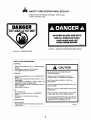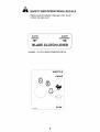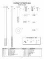
1
Agri-Fab ®
OWNERS
MANUAL
Model No.
45-0362
42" ROUGH CUT
TRAILMOWER
CAUTION:
Read Rules for
Safe Operation
and Instructions
Carefully
_/,/_'_'u_'rdr/
PRINTED IN U.S.A.
NOTE: Your mower deck will require a 12 volt battery to operate.
This battery is NOT included with the deck but must be purchased
separately. Any 12 volt tractor battery with about 230 cold cranking
amps. will operate the machine.
• Safety
• Assembly
• Operation
• Maintenance
• Parts
the fastest way to purchase parts
www.speedepart.corn
FORM NO. 49202 (3/04)
TABLE OF CONTENTS
SAFETY RULES ......................................................
SAFETY AND OPERATIONAL
HARDWARE
ASSEMBLY
DECALS ................ 5,6
CHART ..................................................
............................................................
OPERATION .........................................................
CUSTOMER
RESPONSIBILITIES
REPAIR PARTS ...................................................
DIAGRAM ...................................................
2
7
8-11
12-16
...................... 17-20
STORAGE .................................................................
WIRING
3,4
21
22-26
27
SAFETY RULES
Safe Operation Practices for Tow Behind Mowers
IMPORTANT: THIS CUTTING MACHINE IS CAPABLE OF AMPUTATING HANDS AND FEET AND THROWING
OBJECTS. FAILURE TO OBSERVE THE FOLLOWING SAFETY INSTRUCTIONS COULD RESULT IN SERIOUS
INJURY OR DEATH.
Im
•
•
•
•
•
•
•
•
•
•
•
•
•
•
GENERAL OPERATION
II.
Read, understand, and follow all instructions in the manual and on
the machine before starting.
Read this operator's manual carefully. Become familiar with the
controls and know how to operate your mower properly.
Only allow responsible adults, who are familiar with the instructions,
to operate the machine,
Clear the area of objects such as rocks, toys, wire, etc., which
could he picked up and thrown by the blade.
Be sure the ares is clear of other people before mowing. Stop
machine if anyone enters the ares.
Never carry passengers.
Do not mow in reverse unless absolutely necessary. Always look
down and behind before and while backing.
Slow down before tuming.
Never leave • running machine unattended. Always turn off blades_
and stop engine.
Turn off blades when not mowing.
Mow only in daylight or good artificial light.
Do not operate the machine while under the influence of alcohol or
drugs.
Watch for traffic when operating near or crossing roadways.
Usa extra care when loading or unloading the machine into a trailer
or truck.
Slopes are a major factor related to bes-of-control and tipover accidents,
which can result in severe injury or death. All slopes require extra
caution. If you feel uneasy on it, do not mow if.
DO:
•
Remove obstacles such as rocks, tree limbs, etc.
•
Watch for holes, ruts, or bumps. Uneven terrain could overturn the
machine. Tall grass can hide obatacles.
•
Use slow speed. Choose a low gear so that you wil! not have to
stop or shift while on the slops.
Follow the tractor manufacturer's
recommendations
for
•
wheel weights or counterweights
Keep all movement on the slopes slow and gradual. Do not make
sudden changes in speed or direction.
•
Avoid starting or stopping on a slope. If tires lose traction,
disengage the blades and proceed slowly straight down the slope.
DO NOT:
•
Do not mow near drep-offs, ditches, or embankments. The mower
could suddenly turn over if a wheel is over the edge of a cliff or
ditch, or if an edge caves in.
Exercise special care when mowing around fixed objects in order to
prevent the blades from striking them. Never deliberately run
tractor or mower onto or over any foreign object.
Usa mower only as the manufacturer intended and as described in
this manual.
•
Do not mow on wet grass. Reduced traction could cause sliding.
Do not operate mower if it has been dropped or damaged in any
manner. Always have damage repaired before using your mower.
Always wear safety glasses or eye shields when starting and while
using your mower.
Dress properly. Do not operate mower when barefoot or wearing
open sandals. Wear only solid shoes with good traction when
mowing.
Always make cutting height adjustments before starting your
mower. Never attempt to do this while the engine is running.
Keep your eyes and mind on your mower and the area being cut.
Do not let other interests distract you.
Do not put hands or feet near or under rotating parts. Keep clear of
the discharge opening at all times.
Before cleaning, inspecting, or repairing your mower, stop the
engine and make absolutely sure the blade and all moving parts
have stopped. Then disconnect the spark plug wire and keep it
away from the spark plug to prevent accidental starting.
Do not operate your mower if it vibrates abnormally. Excessive
vibrationis an indicationof damage or unbalanced blades. Stop the
engine,safety check for the cause of the vibrationand repair as
required.
Tragic accidents can occur if the operator is not alert to the presence of
children. Children are often attracted to the machine and the mowing
activity. Never assume that children will remain where you last saw
them.
•
Disengage power to mower, stop engine when transporting or not in
USa,
•
•
•
•
•
•
•
•
•
to improve stability.
•
Do not turn on slopes unless necessary, and then, turn slowly and
gradually downhill, if possible.
Do not attempt to operate your tractor or mower when not in drivers
seat.
•
Mow up and down slopes, not across.
•
•
•
•
SLOPE OPERATION
III.
Never operate your mower withoot proper guards, plates, or other s_ety
devices in place.
3
CHILDREN
•
Keep children out of the mowing area and under the watchful care
of another responsible adult.
•
Be alert and turn machine off if children enter the area.
•
Before and when becking, look behind and down for small children.
•
Never carry children. They may fall off and be sanously injured or
interfere with safe machine operation.
•
Never allow children to operate the machine.
•
Use extra care when approaching blind corners, shrubs, trees, or
other objects that may obscure vision.
IV.
SERVICE
Look for this symbol to point out
important safety precautions. It
means CAUTIONlll BECOME
ALERTlll YOUR SAFETY IS
INVOLVED.
Use extra care in handling gasoline and other fuels. They are
flammable and vapors are explosive,
Use only an approved container.
-Never remove gas cap or add fuel with the engine running.
Allow engine to cool before refueling. Do not smoke.
Never refuel the machine indoors.
Never store the machine or fuel container inside where there
•
is an open flame, such as a water heater.
Never run a machine inside a closed area.
•
Keep nuts and belts, especially blade attachment nuts, tight and
keep equipment in good condition.
•
Never tamper with safety devices. Check their proper operation
regularly.
•
Keep machine free of grass, leaves, or other debris build-up, Clean
oil or fuel spillage. Allow machine to cool before storing.
•
Stop and inspect the equipment if you strike an object. Repair, if
necessary, before restarting.
•
Never make adjustments or repairs with the engine running.
•
Mower blades are sharp and can cut. Wrap the blade(s) or wear
gloves, and use extra caution when servicing them.
•
Check brake operation frequently.
CAUTION: Always disconnect spark
plug wire and place wire where it
cannot contact spark plug in order
to prevent accidental starting when
setting up, transporting, adjusting
or making repairs.
Adjust and service as required.
4
SAFETY
Replace
number.
II
AND OPERATIONAL
decal immediately
See back cover.
KEEPHANDSandFEETAWAY
if damaged.
DECALS
Order
by part
11
ROTATING
BLADES AND
BELTS.
KEEP ALL SHIELDS IN PLACE.
KEEP HANDS AND FEET
FROM UNDER MOWER.
HA12314
HA12315
DANGER ROTATING BLADES DECAL
DANGER DECAL
F
HOW TO USE YOUR MOWER
STOPPING
• Move mower blade clutch lever to "DISENGAGED"
position.
• Move throttle control to "SLOW" position.
• Turn ignition key to "OFF" position.
CAUTION
STARTING
OWNERS MANUAL
I READ AND FOLLOW DIRECTIONS IN
KNOW HOW TO OPERATE BOTH THE
VEHICLE AND THE MOWER ATTACHMENT
• Move mower blade clutch lever to "DISENGAGED"
position.
• Move throttle control to the choke position for cold
engine starts.
• Turn ignition key clockwise to "START' position and
release key as soon as engine starts.
• When engine starts, slowly move throttle control to
"FAST" position.
• Allow engine to warm up.
NEVER ALLOW CHILDREN TO USE THE
EQUIPMENT
DO NOT LEAVE MOWER RUNNING WITH UNIT
UNATTENDED
KEEP ALL SAFETY FEATURES IN PLACE AND
OPERATING
USE
• Sit on tractor seat.
• Move mower blade clutch lever to "ENGAGED"
position.
• Operate tractor at medium ground speed.
(3-4 MPH)
AVOID CONTACT WITH MOVING PART. KEEP
HANDS AND FEET AWAY FROM BLADES
STOP ENGINE BEFORE FUELING,ADJUSTING
OR INSPECTING. DO NOT ADD FUEL TO AN
ENGINE THAT IS RUNNING OR HOT
TRANSPORTING
• Shut off engine.
• Place mower deck in the highest position directly
behind tractor.
HA24431
5
SAFETY AND OPERATIONAL
DECALS
Replace decal immediately if damaged. Order by part
number. See back cover.
BLADES
ENGAGED
\
BLADES
DISENGAGED
BLADE CLUTCH LEVER
HA23265
CLUTCH LEVER OPERATION
DECAL
THROTTLE _
CHOKE
®
©
SLOW
HA23820
....................
6
J
CONTENTS
SHOWN
OF PARTS BAG
FULL SIZE
f
B
j
NOT SHOWN
K
FULL SIZE
I
f
I
I
I
M
N
J
I
f
J
I
I
J
I
J
J
REF.
A
B
C
D
E
F
G
QTY.
1
2
2
2
3
2
1
DESCRIPTION
Hex Bolt, 1/2" x 7"
Hex Bolt, 1/4" x 7-1/2"
Hex Bolt, 3/8" x 2-3/4"
Hex Bolt, 5/16" x 3/4"
Hex Bolt, 1/4" x 3/4"
Screw, Self Tapping #10 x 1/2"
Hex Lock Nut, 1/2"
REF.
H
I
J
K
L
M
N
0
7
QTY.
2
2
1
2
2
2
2
1
DESCRIPTION
Hex Lock Nut, 3/8"
Hex Lock Nut, 5/16"
Hex Lock Nut, 1/4"
Hex Nut (SEMS), 1/4"
Flat Washer, 3/8"
Clip, 3/8"
Plastic Nut
Key
O
ASSEMBLY
TOOLS
(1)
(2)
(2)
(2)
(2)
REQUIRED
FOR ASSEMBLY
INSTALL
5/16" Wrench
7/16" Wrenches
1/2" Wrenches
9/16" Wrenches
3/4" Wrenches or Adjustable Wrenches
•
•
•
•
CLUTCH
TO TOWBAR
TUBE
Place Clutch Cable forward along Towbar Tube.
Spread ends of two Cable Clips and place around
Clutch Cable.
Place Clutch Cable on top of Towbar Tube and align
Cable Clips with bolt holes in Towbar Tube.
Secure with two #10 Screws.
UNPACKING
INSTALL
Enclosed in packing crate are (3) items:
1. Mower Deck
2. Tow Bar Hitch Assembly
3. Box of Parts consisting of:
•
Rear Roller
•
Rear Roller Bracket
•
Your Trail Mower requires a 12 volt battery to operate.
The battery is NOT included with the unit. It must be
purchased separately.
• Remove four screws and the Battery Cover from
the Mower and set them aside.
Bag of Parts (See page 7)
•
•
ENGINE
OIL
VERY IMPORTANT:
Engine must be filled with oil before operation. See OIL
& FUEL RECOMMENDATIONS
in engine Owner's
Manual for correct filling instructions and oil fill capacity.
INSTALL TOWBAR
QUADRANT
•
•
•
•
•
•
•
•
TUBE
BATTERY
TO REAR
•
•
Place the Battery Hold Down on top of the Battery.
Secure the Battery to the Mower Deck with two
1/4 x 7-1/2 hex bolts.
•
Open the terminal
Hold Down.
•
Connect the Red Wire to the positive (+) battery
terminal using a 1/4 x 3/4 hex bolt and 1/4 SEMS
nut. Tighten securely.
Connect the Black Wire to the negative (-) battery
terminal using a 1/4 x 3/4 hex bolt and 1/4 SEMS
nut. Tighten securely.
Close the terminal access doors.
•
•
Remove Hex Bolts and lift Front Drive Cover from
mower housing.
Rest end of Tow Bar Tube on front edge of mower.
Feed Wire Harness in end of Tow Bar Tube through
large hole in back wall of Rear Quadrant.
Place Towbar Tube into Rear Quadrant, align holes
and insert 3/8 x 2-3/4 Hex Bolt through quadrant
and rear hole of Tube.
Install two Plastic Nuts into the square holes in the
Mower Deck under the Battery Cover.
Place the Battery on the Mower Deck between the
two Plastic Nuts.
•
Replace
screws.
INSTALL
LEVER
•
Secure tightly with 3/8 Hex Lock Nut and then
loosen 1/4 turn to allow Tube to pivot freely inside
Rear Quadrant.
Assemble a 3/8 Flat Washer onto a 3/8 x 2-3/4 Hex
Bolt.
Insert Bolt and Washer into slot in Rear Quadrant
and into hole in Towbar Tube.
•
•
•
Secure Tightly with 3/8 Flat Washer and 3/8 Hex
Lock Nut, then loosen 1/4 turn to allow Tube to
pivot freely inside Rear Quadrant.
•
NOTE: Towbar Tube must pivot freely inside Rear
Quadrant when Latch is pulled from notch.
8
access doors on the Battery
Battery Cover and secure it with the four
CLUTCH
CABLE
TO CLUTCH
Remove outer 5/16 Nut from end of Clutch Cable
Housing. (See Fig. 1)
Turn inner 5/16 Nut to bottom of thread.
Insert Cable and outer 5/16 Nut through slotted hole
in Cable Guide of Hitch Assembly. The outer 5/16
Nut must be cocked sideways to insert through
slotted hole of Cable Guide.
Reinstall outer 5/16 Nut to the cable housing to
secure Cable Harness to Cable Guide.
Install Mounting Anchor of Clutch Cable to Clutch
Lever using 1/4 x 3/4 Hex Bolt and 1/4 Lock Nut.
Tighten 1/4 Lock Nut securely and then loosen
approximately two turns to allow Mounting Anchor
to pivot freely on bolt.
ASSEMBLY
TERMINAL ACCESS DOORS
1/4 X 3/4 HEX BOLT &
BATTERY
COVER
1/4 HEX NUT (SEMS)
N
BLACK WIRE
SCREW (4)
BATTERY HOLD DOWN
1/4 X 7-1/2 HEX BOLT
PLASTIC NUT
RED WIRE
1/4 X 7-1/2
HEX BOLT
3/8 X 2-3/4 HEX BOLT
CLUTCH LEVER
3/8 FLAT WASHER
#10 SCREW (2)
CABLE CLIP (2)
.3/8 FLAT WASHER
V
3/8 HEX LOCK NUT
1/4 X 3/4 HEX BOLT
CLUTCH CABLE
5/16 HEX NUT (2)
FIG. 1
MOUNTING ANCHOR
9
1/4" HEX LOCK NUT
ASSEMBLY
INNER NUT
CLUTCH
CABLE ADJUSTMENT
/
/
•
•
•
/
/
Remove four screws from Rear Drive Cover. Lay aside
cover and screws.
/
/
/
OUTER NUT
Place Clutch Lever in "DISENGAGED" position
The Cable should be under slight tension but should
not pull the Clutch Lever more than 1/8" away from
the Switch Body.
NOTE: If the Plunger extends more than 1/8" out from
the switch body, the cable tension is too tight and the
Engine will not start.
TO INCREASE CABLE TENSION
• Place Blade Clutch Lever in the "DISENGAGED"
position.
• Loosen the inner nut on the Clutch Cable.
• Tighten the outer nut on the Clutch Cable.
TO DECREASE CABLE TENSION
• Place Blade Clutch Lever in the "DISENGAGED"
•
•
•
SWITCHE]
BODY
position.
Loosen the outer nut on the Clutch Cable.
Tighten the inner nut on the Clutch Cable.
Repeat the above procedure until you have the
correct tension.
o
©
\
\
\
\\
IDLERE]
PULLEY
ENC
PULLEY
PLUNGER
BLADEE]
ILLEY
CLUTCH LEVER
FOURE]
SCREWS
CLUTCH LEVER
FIG. 2
10
ASSEMBLY
INSTALL
•
•
•
REAR ROLLER
TO DECK
Install Rear Roller Mounting Bracket to rear of deck
using two 5/16 x 3/4 Hex Bolts and two 5/16 Hex
Lock Nuts. (See Fig. 3.)
Install Roller to Rear Roller Bracket using 1/2 x 7
Hex Bolt and 1/2 Hex Lock Nut.
Make sure Roller turns freely on Bolt.
5/16 X 3/4 HEX BOLTSB
AND 5/16 HEX LOCK NUTS
"h
ROLLER
1/2 X 7 HEX BOLT
REAR ROLLERB
MOUNTING BRACKET
1/2 HEX LOCK NUT
FIG. 3
11
OPERATION
KNOW YOUR MOWER
READ THIS OWNER'S MANUAL AND SAFETY RULES BEFORE OPERATING
YOUR MOWER.
Compare the illustrations with your mower to familiarize yourself with the location of various controls and adjustments.
Save the manual for future reference.
HEIGHT ADJUSTMENT
MOWER BLADE
CLUTCH LEVER
STRAP
IGNITION
KEY SWITCH
HEIGHT ADJUSTMENT
LIFT LEVER
TOW HITCH OFFSET
ADJUSTMENT
3HT
ADJUSTMENT
STRAP
TOW BAR HEIGHT
ADJUSTMENT
THROTTLE CONTROL
FIG. 4
MOWER BLADE CLUTCH LEVER - Starts and stops
mower blade rotation.
THROTTLE CONTROL - Controls engine speed, engine
shut-off and engine choke.
IGNITION KEY SWITCH - Used to start and stop
engine.
HEIGHT ADJUSTMENT LIFT LEVER - Raise and lower
mower to different cutting heights.
HEIGHT ADJUSTMENT STRAP - Controls cutting
height,
TOW BAR HEIGHT ADJUSTMENT - To level mower
front to rear.
TOW HITCH OFFSET ADJUSTMENT - To adjust
mower deck offset from tractor center.
12
OPERATION
The operation of any mower can result in foreign objects being thrown into the eyes,
which can result in severe eye damage. Always wear safety glasses or eye shields
before starting your mower and while mowing. We recommend wide vision safety mask
for over the spectacles or standard safety glasses.
CHILDREN
,_
Tragic
occur if
not the
alert
to the presence
of children.
Childrenaccidents
are often can
attracted
to the
the operator
machine isand
mowing
activity. Never
assume that children will remain where you last saw them.
HOW TO USE YOUR
ATTACHING
MOWER
STOPPING
•
MOWER BLADES-
•
•
Move mower blade clutch switch to "DISENGAGED"
position.
•
ENGINE•
•
MOWER
TO TRACTOR
Place mower behind tractor and back tractor up to it
for attaching. (See Fig. 5)
Slide tow bar of mower over tractor draw bar so that
the hitch pin holes line up.
Insert hitch pin until it extends through the bottom of
the tow bar.
Insert hair cotter pin through hitch pin.
Move throttle control to "SLOW" position.
NOTE:
Failure to move throttle control to "SLOW"
position or allowing engine to idle before stopping may
cause engine to "backfire".
•
•
Turn ignition key to "OFF" position and remove key.
Always remove key when leaving tractor to prevent
unauthorized use.
Never use choke to stop engine.
TO USE CHOKE
CONTROL
TRACTOF
HITCH PIN
OR MOWER
CLEVIS PIN
Use choke control whenever you are starting a cold
engine. Do not use to start a warm engine.
•
•
•
To engage choke control, move throttle control to
choke position.
After engine has started move throttle control to full
throttle position.
TO USE THROTTLE
HAIR COTTER PIN
FIG. 5
CONTROL
Always operate engine at full throttle.
•
•
Operating engine at less than full throttle reduces
the battery charging rate.
Full throttle offers the best mower performance.
TRANSPORTING
•
•
TRACTOR
DRAWBAR
Shut off engine.
Place mower deck in the highest position directly
behind tractor.
13
OPERATION
BEFORE
STARTING
ENGINE
•
Fill engine with oil. (See engine manual for proper
procedure and requirements.
•
Add gasoline. Fill fuel tank using fresh clean
unleaded gasoline. (See tractor manual for safe
filling procedure and storage instructions)
STARTING
•
•
•
•
TO START
Adjust mower cutting height.
Start mower engine.
Move throttle to fast position.
Move mower blade lever to"ENGAGED"
BREAKING
CAUTION:
FILL TO BOTTOM OF FUEL TANK FILLER
NECK. DO NOT OVERFILL. WIPE OFF
ANY SPILLED OIL OR FUEL. DO NOT
STORE, SPILL OR USE GASOLINE NEAR
OPEN FLAME.
ENGINE
MOWING
•
•
•
,_
PROCEDURES
NEVER CARRY CHILDREN. THEY MAY
FALL OFF AND BE SERIOUSLY INJURED
CAUTION:
OR INTERFERE WITH SAFE OPERATION
Mowing should be started with tow vehicle in low
gear and speed increased only as mowing conditions will
safely permit.
Mower will perform at its best when engine throttle
is set for full throttle.
NOTE: If at a high altitude (above 3000 feet) or in cold
temperatures (below 32°F), the carburetor fuel mixture
may need to be adjusted for best engine performance.
See "TO ADJUST CARBURETOR"
in your Engine
Owner's Manual
Always operate mower engine at full throttle when
mowing to assure better mowing performance and
proper discharge of matedal. Regulate ground speed by
selecting a low enough gear to give the mower cutting
performance as well as the quality of cut desired.
When operating any attachment select a ground
speed that will suit the terrain and give best
performance of the attachment being used.
CAUTION:
,_
MOWER
CAUTION:
TRAGIC ACCIDENTS CAN OCCUR IF
THE OPERATOR IS NOT ALERT TO
THE PRESENCE OF CHILDREN.
CHILDREN ARE OFTEN ATTRACTED
TO THE MACHINE AND THE MOWING
ACTIVITY. NEVER ASSUME THAT
CHILDREN WILL REMAIN WHERE YOU
LAST SAW THEM.
Move mower blade clutch lever to"DISENGAGED"
position.
Move throttle control to the choke position for cold
engine starts. For warm engine starts move throttle
control to midway between "FAST" and "SLOW"
positions.
Turn ignition key clockwise to "START" position and
release key as soon as engine starts. Do not run
starter continuously for more than fifteen seconds
per minute. If engine does not start after several
attempts, move throttle control to "FAST" position,
wait a few minutes and try again.
When engine starts, slowly move throttle control to
"FAST" position.
Allow engine to warm up for a few minutes before
engaging mower blade clutch lever.
•
IN YOUR
position.
Break in your belts, pulleys, and engine before you
actually begin mowing.
•
Start engine, engage blade control to start blades
rotating and allow blades to rotate for approximately
five minutes to break in mower and engine.
When starting engine for the first time or if engine has
run out of fuel, it will take extra cranking time to move
fuel from the tank to the engine.
•
THE MOWER
MOWER FOR ANY OBJECTS THAT COULD
CHECK
AREA FROM
UNDERUNDER
AND AROUND
BE THROWN
MOWER.
MAKE SURE THAT MOWER DISCHARGE
AREA IS CLEAR.
IMPORTANT:
Avoid prolonged mowing of ditches
with slopes greater than 15 degrees. Small engines
become starved for oil at angles greater than 15
degrees and should only be used for brief periods
on such slopes. Be sure the engine is filled to the
maximum oil level when mowing on slopes.
14
OPERATION
MOWER
HEIGHT
ADJUSTMENT
FRONT
CAUTION:
SHUT OFF MOWER ENGINE AND REMOVE
_
To obtain the best cutting results, the mower housing
should be adjusted so that the front is approximately
1/4" to 3/4" lower than the rear. To check front to back
adjustment measure from the bottom edge of the deck
to the ground at both front and rear of the deck.
PARK PLUG
WIREANY
FROM
SPARK PLUGTO
BEFORE
MAKING
ADJUSTMENTS
THE MOWER
TO ADJUST MOWER FROM FRONT TO BACK
The cutting height range is approximately 1-1/2 to 5
inches. The heights are measured form the ground to
the blade tip with the engine not running. These heights
are approximate and may vary depending upon soil
conditions, height of brush and types of brush being
mowed.
CUTTING
•
•
•
•
•
•
HEIGHT
TO BACK RAKE ADJUSTMENT
•
•
•
•
ADJUSTMENTS
Remove two hair cotter pins from two clevis pins in
the tow bar adjustment. (See Fig. 6)
Remove two clevis pins from tow bar adjustment.
Raise or lower the tow bar to obtain the proper front
to back adjustment.
Reassemble two clevis pins to tow bar adjustment
and secure with two hair cotter pins.
To adjust the mower cutting height remove hair
cotter pin from locating pin. (See Fig. 6)
Apply down pressure to height adjustment lift lever.
Remove the locating pin from the height adjustment
strap.
Move height adjustment strap up or down to align it
with the desired hole in the height adjustment strap.
Reassemble locating pin to the height adjustment
strap and secure with hair cotter pin.
Make sure that both side height adjustment straps
are adjusted to the same height.
HAIR COTTER PIN
LOCATING
PIN
HEIGHT ADJUSTMENT
_'_
STRAP
HEIGHT ADJUSTMENT
CUTTING
HEIGHTS
GROUND LEVEL
/
CUTTING HEIGHT --1_-
FIG. 6
15
OPERATION
TOW HITCH OFFSET
ADJUSTMENT
CAUTION:
SHUT OFF MOWER ENGINE AND REMOVE
This mower has been designed to run offset from the
center of the tow vehicle. This allows the operator to
drive along side high brush with the tow vehicle while
cutting down the brush beside him. The adjustable
hitch gives you three offset cutting positions plus
straight behind for narrow paths.
_lb
PARK PLUG
WIREANY
FROM
SPARK PLUGTO
BEFORE
MAKING
ADJUSTMENTS
THE MOWER
TO ADJUST
THE OFFSET
HITCH
•
Pull back the pivot latch from the notch of the front
quadrant. Adjust the hitch tube to the desired
offset and release the pivot latch into the notch of
the quadrant. (See Fig. 8)
•
Pull back the pivot latch from the notch of the rear
quadrant. Adjust the hitch tube to the
corresponding notch of the front quadrant and
release the pivot latch into the notch.
IMPORTANT: The hitch tube must be assembled to
the same offset notch in both the front and rear
MODEL 45-0362
The adjustable hitch of this mower can be set in seven
positions including straight and offsets of 9", 17" and
23" on both sides. (See Fig. 7)
quadrants.
9" OFFSET
ON MODEL
45-0362
OFFSET
_17,, OFFSET
ON MODEL
45-0362
I
_)
OFFSET
_/
ATCH
23"OFFSET
LATCH
17" OFFSE'I
, II- JO;_
9 _
STRAIGH1
_
23" OFFSET ON MODEL 45-0362
/°
REARQUADRANT
FIG. 7
FIG. 8
16
CUSTOMER
GENERAL
RESPONSIBILITIES
RECOMMENDATIONS
Once a year you should replace the spark plug,
clean or replace air filter, and check blades and
belts for wear. A new spark plug and clean air filter
assure proper air-fuel mixture and help your engine
run better and last longer.
The warranty on this Vehicle does not cover items that
have been subjected to operator abuse or negligence. To
receive full value from the warranty, operator must
maintain unit as instructed in this manual.
BEFORE EACH USE
Some adjustments will need to be made periodically to
properly maintain your unit.
All adjustments in the Service and Adjustments section of
this manual should be checked at least once each season.
•
•
•
Check engine oil level.
Check blade operation
Check for loose fasteners.
LUBRICATION
Keep unit well lubricated (See "LUBRICATION CHART").
MAINTENANCE
SCHEDULE
FILL IN DATES
AS YOU COMPLETE
REGULAR SERVICE
SERVICE
Change Engine Oil
DATES
I1_
Inspect Spark Arrester Muffler
Inspect Air Screen
V/
Check and Clean Air Cleaner
II_
Replace Air Cleaner Cartridge
Clean Engine Cylinder Fins
Replace Spark Plug
[
Lubricate Spindle
1 - Change
I1_
more often when operating unaer a heavy load or in high ambient temperatures,
LUBRICATION CHART
2- Service more often when operating in dirty or dusty conditions.
WHEEL PIVOT _3_
SPINDLE _2_
O
REFER TO ENGINE MANUAL
Q
GENERAL PURPOSE GREASE
@
DRY LUBRICANT
WHEEL_2),_
IMPORTANT: DO NOT OIL OR GREASE PIVOT POINTS.
VISCOUS LUBRICANTS WILL A'R'RACT DUST AND DIRT
THAT CAN CAUSE WEAR ON PIVOT POINTS. IF YOU
FEEL THEY MUST BE LUBRICATED, USE ONLY A DRY
POWERED GRAPHITE TYPE LUBRICANTS.
SWIVEL_2_'
QUADRANT _3)
17
WHEEL PIVOT _3_
CUSTOMER
BLADE
RESPONSIBILITIES
CARE AND SERVICE
BLADE ASSEMBLY
CAUTION:
BARE HANDS. CARELESS OR IMPROPER
DO NOT HANDLE MOWER BLADES WITH
HANDLING MAY RESULT IN SERIOUS
INJURY.
BLADE CARE
For best results mower blades must be kept sharp. The
blades can be sharpened with a file or on a grinding
wheel. Do not attempt to sharpen blades while they are
still on the mower.
BLADE SERVICE
(Refer to fig. 9)
TO
•
•
•
REMOVE BLADE ASSEMBLY FROM DECK
Remove cotter pin from the spindle shaft.
Remove nut and washer from the spindle shaft.
Pull blade assembly off the spindle shaft. (Watch for
a key in the spindle shaft.)
TO
•
•
•
REMOVE BLADES FROM BLADE ASSEMBLY.
Remove cotter pin from the blade bolt.
Remove nut from the blade bolt.
Remove blade from the blade assembly.
FIG. 9
WARNING:
SHUT OFF MOWER ENGINE AND REMOVE
SPARK PLUG WIRE FROM SPARK PLUG
BEFORE MAKING ANY ADJUSTMENTS OR
REPAIRS TO THE MOWER.
BLADE SHARPENING
•
Blades can be sharpened with a file or grinding wheel.
NOTE: When sharpening blades take care to maintain
blade balance. Sharpen both blades equally even if one
blade does not need to be sharpened. Check balance by
weighing each blade to make sure they are equal in weight.
CLEANING
Water pressure from a garden hose will remove fresh
clippings from the underside of the mower. Clean mower
after each mowing.
CAUTION:
,_
DALLY MAINTENANCE
IFYOUR BLADE
SHOWWEAR,
REPLACE
THEM BOLTS
WITH FACTORY
REPLACEMENTS ONLY.
Make sure all nuts and bolts are tight, cotter pins and
retainer springs are secure. Keep blades sharp. Observe
all Safety Precautions. Keep mower well lubricated.
TO REINSTALL BLADES
•
Assemble a blade bolt through a flat washer, a blade
and then another flat washer.
•
Assemble the bolt through the hole in the stump
plate and the blade hub assembly.
•
Assemble a flat washer and nut onto the blade bolt.
•
Tighten nut, then loosen just until blade can pivot.
•
Install a cotter pin to secure the nut.
TO
•
•
•
•
THE MOWER
REPAIR PARTS
Your rotary mower has been produced with components
designed for your unit. Although standard V-belts,
bearings, blades, pulleys, etc. may look like parts used
on your rotary mower, while similar in appearance many
are of a different construction and could in some cases
cause a malfunction in the operation of the machine.
REINSTALL BLADE ASSEMBLY TO MOWER
Reinstall key in spindle shaft, if necessary.
Install the blade assembly onto the spindle shaft.
Secure with flat washer and nut.
Torque the spindle shaft and nut to 15 FT. LBS. and
secure with a hair cotter pin.
For continued satisfactory performance use only repair
parts supplied by the manufacturer. See the dealer
where the mower was purchased for factory replacement
parts.
18
CUSTOMER
RESPONSIBILITIES
INNER NUT
CLUTCH
CABLE ADJUSTMENT
/
•
\
\
,
\
OUTER NUT
Remove four screws from Rear Drive Cover. Lay aside
cover and screws.
• Place Clutch Lever in "DISENGAGED" position
• The Cable should be under slight tension but should
not pull the Clutch Lever more than 1/8" away from
the Switch Body.
NOTE: If the Plunger extends more than 1/8" out from
the switch body, the cable tension is too tight and the
Engine will not start.
TO INCREASE CABLE TENSION
• Place Blade Clutch Lever in the "DISENGAGED"
position.
• Loosen the inner nut on the Clutch Cable.
• Tighten the outer nut on the Clutch Cable.
TO DECREASE
CABLE TENSION
• Place Blade Clutch Lever in the "DISENGAGED"
SWITCHD
BODY
position.
• Loosen the outer nut on the Clutch Cable.
• Tighten the inner nut on the Clutch Cable.
• Repeat the above procedure until you have the
correct tension.
©
1/8""
©
IDLERD
PULLEY
ENC
PULLEY
PLUNGER
BLADED
PULLEY
CLUTCH LEVER
19
o
CUSTOMER
RESPONSIBILITIES
INSTALLING NEW V-BELT
V-BELT REPLACEMENT
•
•
V-belt must be replaced if it becomes stretched to
the point that it can no longer be adjusted, or if it
becomes frayed or otherwise can not function
properly.
Move Blade Clutch Lever to the "DISENGAGED"
position.
•
•
•
•
I,_
DISCONNECT
CAUTION:
SPARK PLUG WIRE
•
•
REMOVING OLD V-BELT
• Remove Rear Drive Cover.
• Remove Front Drive Cover.
• Remove Hair Pin and Clevis Pin from Clutch Cable.
• Loosen two Rear Belt Guides and pivot them away
from Blade Pulley.
• Remove V-belt from around Blade Pulley.
• Remove one small Hair Pin from Belt Keeper Rod
and slide Belt Keeper Rod to the side.
• Pull V-belt down from around Engine Pulley and
remove V-belt from Mower.
•
•
Feed new V-belt between the two belt guides at the
Engine Pulley.
Place V-belt up and around the Engine Pulley. Check
to make sure the V-belt is seated properly in the
groove of the Engine Pulley.
Place V-belt along inside of Idler Pulley.
Wrap V-belt down around Blade Pulley, placing Belt
inside of Rear Belt Guides.
Reinstall V-belt Keeper Rod and secure with Small
Hair Pin. Check to make sure V-belt is over top of
Keeper Rod.
Reposition and retighten two Rear Belt Guides at the
rear of the Blade Pulley. Leave approximately 1/16"
between Guides and Pulley.
Reinstall Clevis Pin and Hair Pin into Clutch Cable.
Reinstall Front Drive Cover and Rear Drive Cover.
BELT GUIDES
HAIRPIN AND CLEVIS PIN
BLADE PULLEY
REAR BELT GUIDES
ENGINE PULLEY
BELT KEEPER ROD
V-BELT
20
STORAGE
Immediately prepare your mower for storage at the end
of the season or if the unit will not be used for 30 days
or more.
ENGINE OIL
Drain oil (with engine warm) and replace with clean
engine oil. (See engine manual)
MOWER
CYLINDER
When the mower is to be stored for a period of time,
clean it thoroughly, remove all dirt, grease, leaves, etc.
Store in a clean dry area.
•
Clean entire mower (See =CLEANING")
•
Lubricate as shown in the Customer Responsibilities
section of this manual.
•
Be sure that all nuts, bolts, screws, and pins are
securely fastened. Inspect moving parts for
damage, breakage and wear. Replace if necessary.
•
Touch up all rusted or chipped paint surfaces; sand
lightly before painting.
•
•
•
•
OTHER
•
•
Do not store gasoline from one season to another.
Replace your gasoline can if your can starts to rust.
Rust and/or dirt in your gasoline will cause
problems.
•
If possible, store your unit indoors and cover it to
give protection from dust and dirt.
•
Cover your unit with a suitable protective cover that
does not retain moisture. Do not use plastic.
Plastic cannot breathe which allows condensation to
form and will cause your unit to rust.
IMPORTANT:
NEVER COVER MOWER WHILE
ENGINE AND EXHAUST ARE STILL WARM.
CLEANING
IMPORTANT:
FOR BEST PERFORMANCE, KEEP
MOWER HOUSING FREE OF BUILT-UP BRUSH AND
TRASH. CLEAN THE UNDERSIDE OF YOUR
MOWER AFTER EACH USE.
CAUTION: Disconnect spark plug wire
from spark plug and place wire where it
cannot come in contact with the spark
plug.
•
•
•
Remove spark plug.
Pour one ounce (29 ml) of oil through spark plug
hole into cylinder.
Pull starter handle slowly a few times to distribute
oil.
Replace with new spark plug.
CAUTION:
Clean the underside of your mower by scraping to
remove build-up of brush and trash.
Keep finished surfaces and wheels free of all
gasoline, oil, etc.
We do not recommend using a garden hose to
clean mower unless the electrical system, muffler,
air filter, and carburetor are covered to keep water
out. Water in engine can result in shortening engine
life.
Never store the mower with
where
fumes
may
an aopen
flame or
gasoline
in the
tankreach
inside
building
spark. Allow the engine to cool before
storing in any enclosure.
ENGINE
•
Never use engine or carburetor cleaner products in
the fuel tank or Permanent damage may occur.
•
Use fresh fuel every season.
NOTE: Fuel stabilizer is an acceptable alternative in
minimizing the formation of fuel gum deposits during
storage. Add stabilizer to gasoline in fuel tank or
storage container. Always follow the mix ratio found on
stabilizer container. Run engine at least 10 minutes
after adding stabilizer to allow the stabilizer to reach the
carburetor. Do not drain the gas tank and carburetor if
using fuel stabilizer.
21
42" ROUGH
CUT TRAILMOWER
- MODEL
45-0362
o
©
22
42" ROUGH
CUT TRAILMOWER
- MODEL
45-0362
ITEM
PART NO.
DESCRIPTION
ITEM
PART NO.
DESCRIPTION
1.
HA24255
MOWER DECK
48.
HAl15321
SCREW 5/16-18 X 5/16 SOC. SET
2.
3.
HA24378
HA23193
GUARD WHEEL
50.
43555
WASHER 7/16" LOCK
SCREW 3/8-16 X 1-1/4 THD. FORMING
51.
HA181668
BOLT 7/16-20 X 1-1/4 HEX HEAD
4.
HA24292
BRACKET
52.
25051
COVER, GAS TANK
5.
HA24293
ROD BELT GUIDE
53.
25265
6.
HA3090
PIN HAIR COTTER
55.
43182
COVER, FRONT DRIVE
BOLT 5/16-18 X 3/4 HEX HEAD
7.
HA24294
8.
HA24295
V-BELT (B SEC. 60" O.C.)
CHANNEL CLUTCH LEVER
56.
57.
43064
25264
9.
45100
BOLT 1/2-13 X 4" HEX HEAD
58.
HA23732
COVER, REAR DRIVE
TANK GASOLINE
10.
HA120396
WASHER 1/2 FLAT
59.
HA24317
PLATE FUEL TANK
11.
43262
NUT 1/2-13 HEX LOCK
60.
HA163318
SCREW 1/4-14 X 7/8 TAPPING PAN HEAD
12.
HA14232
WASHER FLAT
61.
HA23733
CAP GASOLINE
13.
HA24296
ROD CLUTCH LINK
62.
48837
HOSE FUEL TANK LONG
14.
44101
43081
63.
64.
HA24455
HA23792
HOSE FUEL TANK SHORT
15.
PIN, COTTER 3/32" X 3/4"
WASHER FLAT 5/16" STD. WRT.
CLAMP FUEL LINE
16.
HA24297
SPRING CLUTCH
65.
HA23791
FILTER FUEL LINE
17.
49165
CLUTCH CABLE ASSY
66.
48095
PIPE
BELT GUIDE
NUT 5/16-18 HEX LOCK
TANK
STRAP, CLUTCH ADJUSTING
67.
48096
CAP
68.
69.
HA24310
HA12138
BRACKET
43016
BOLT, 1/4-20 X 1" HEX HEAD
NUT 1/4-20 HEX LOCK
21.
25262
BRACKET
70.
HA12315
22.
HA23199
SWITCH INTERLOCK
71.
HA12314
DECAL DANGER (HAND)
DECAL DANGER
24.
712-0121
NUT #10-24 HEX
72.
HA24431
DECAL OPERATION/CAUTION
25.
47078
SCREW #10-24 X 3/4"
74.
HA126145
BOLT 1/2-13 X 7" HEX HEAD
26.
27.
48840
48298
SCREW 1/4-20 WASHER HEAD
75.
43982
28.
HA24300
CLIP, CORD
WHEEL MOUNTING
BRACKET L.H.
76.
77.
HA22981
HA24298
PIN, CLEVIS 1/4" X 5/8"
BELT GUIDE
29.
HA24301
WHEEL MOUNTING
BRACKET
78.
49156
30.
HA4143
WASHER FLAT
79
43013
ROD, CABLE GUIDE
NUT 1/4-20 HEX
31.
HA137258
PIN COTTER 3/16" X 1-3/4"
80.
44488
WHEEL BEARING
32.
HA24308
TIRE
81.
HA23754
SOLENOID
33.
HA23229
CAP HUB
82.
HA23749
STARTER SWITCH
34.
HA24309
STRAP ADJUSTING
83.
HA23750
SWITCH MOUNTING
35.
HA6979
WASHER FLAT
84.
HA23757
SWITCH COVER
36.
43020
BOLT 1/2-13 X 1-1/2 HEX HEAD
85.
HA23752
KEY
37.
43019
NUT 1/2-13 HEX JAM
86.
25286
38.
HA23220
PIN LOCATING
87.
49201
PLATE, SWITCH MOUNTING
THROTTLE
39.
40.
47134
HA24311
PIN HAIR COTTER
88.
45040
SCREW, #10-24 X 1/2
CHAIN DEFLECTOR
89.
736-0722
41.
HA24312
ROD CHAIN
90.
49198
LOCK WASHER, #10
BATTERY HOLD DOWN
42.
HA24313
BRACKET CHANNEL
91.
49199
BOLT, BATTERY
43.
HA9131
SCREW SELF THREADING
92.
49200
44.
25263
PLATE ENGINE MOUNTING
93.
25287
NUT, PLASTIC
BATTERY COVER
45.
280H070130E1* ENGINE, 14.5 HP
HA24457
PULLEY
94.
48840
SCREW, 1/4-20 X 1/2 HEX HEAD
46.
47.
HA3073
* Order engine repair parts from your nearest Briggs & Stratton
dealer.
18.
19.
25291
43661
20.
INTERLOCK
KEY 1/4" SQ. X 1"
MOUNTING
.08" X 1.58"
R.H.
ROLLER
ROLLER MOWER
SPRING RETURN
SpeedEPartthe
ra..e., to,urchparts
.e www.speedepart.com
23
NUT
42" ROUGH
CUT TRAILMOWER
- MODEL
45-0362
24
42" ROUGH
CUT TRAILMOWER
- MODEL
45-0362
ITEM
PART NO.
DESCRIPTION
1.
64906
IDLER MOUNTING
2.
43070
WASHER FLAT
3.
4.
64899
24472
IDLER ARM
5.
6.
43003
43062
WASHER 3/8" LOCK
7.
49148
SPACER
8.
HA21341
9.
43054
IDLER PULLEY (FLAT)
BOLT 3/8-16 X 2" HEX HEAD
10.
43082
NUT 3/8-16 HEX LOCK
11.
HA22981
GUIDE BELT
12.
HA22224
SCREW 3/8-16 X 3/4 SELF TAPPING
13.
14.
43087
HA15200
BOLT 3/8-16 X 1-1/4" HEX HEAD
15.
HA21362
NUT 3/8-16 NYLOCK
16.
HA24367
GREASE FITTING
17.
HA24278
18.
HA24280
HUB (WITH STUDS)
BEARING
19.
64913
HUB BLADE
20.
21.
49148
HA24282
SHAFT SPINDLE
22.
HA3073
KEY 1/4" SQ X 1"
23.
HA456151
WASHER 13/16 X 1-1/2 X .134 FLAT
24.
HA427639
NUT 3/4-16 SLOTTED HEX
25.
26.
43010
HA24624
PIN 1/8" X 1" COTTER
27.
HA24288
BLADE
28.
HA24625
WASHER - FLAT
29.
HA24592
BOLT - 7/8-9 X 2-1/4 HEX BOLT
30.
HA137258
PIN 3/16 X 1-3/4 COTTER
31.
HA24593
NUT 7/8-9 SLOTTED
32.
43353
WASHER 1/2 MED. LOCK
33.
HA120371
NUT 1/2-20 HEX
34.
HA24290
PULLEY SPINDLE
35.
64902
BRAKE
36.
49155
TRUNNION
37.
49160
BRAKE ROD
38.
HA20186
SPRING
BRACKET
BUSHING
BOLT 3/8-16 X 1-1/2" HEX HEAD
WASHER FLAT
SEAL O-RING
DISC BLADE MOUNTING
OIi##u ;rd/'i
HEX
thefastestwaytopurchaseparts
www.speedepart.com
25
42" ROUGH
CUT TRAILMOWER
- MODEL
45-0362
ITEM
PART NO.
DESCRIPTION
16.
17.
43012
43013
BOLT 1/4-20 X 3/4 HEX HEAD
HA20186
SPRING EXTENSION
19.
HA23265
DECAL CLUTCH LEVER
4.
44180
BOLT 5/16-18 X 2' HEX HEAD
20.
64910
BRACKET DRAWBAR ADJUSTMENT
5.
43064
NUT 5/16-18 HEX LOCK
21.
HA24326
DRAWBAR SWIVEL
6.
64909
HITCH ASSEMBLY
22.
HA5074
FITTING GREASE
7.
HA180132
43509
23.
24.
HA15200
43003
WASHER
8.
BOLT 3/8-16 X 2-1/4 HEX HEAD
BOLT 3/8-16 X 2-3/4 HEX HEAD
9.
43070
WASHER 3/8 FLAT
25.
43087
BOLT 3/8-16 X 1-1/4 HEX HEAD
10.
43082
NUT 3/8-16 HEX LOCK
26.
HA24330
PIN CLEVIS
11.
HA23636
PIN CLEVIS
27.
HA3341
12.
47134
PIN HAIR COTTER .08 X 1.58
29.
HA23761
PIN HAIR COTTER, 5/32"
CLIP HOSE 3/8"
13.
49157
LEVER CLUTCH
30.
HA9411666
SCREW #10-16 X 1/2 SELF TAPPING
14.
43062
BOLT 3/8-16 X 1-1/2 HEX HEAD
31.
49193
WIRE HARNESS
15.
HA19445
SPRING COMPRESSION
ITEM
PART NO.
DESCRIPTION
1.
25273
2.
HA24441
TUBE DRAWBAR
STRAP HITCH
3.
O/l##uA;rdrl
(MODEL 45-0361)
thelastest
NUT 1/4-20 LOCK
WASHER 3/8 LOCK
(See page 27)
topurchase
parts www.speedepart.com
26
RED WIRE
BATTERY CHARGE
STARTER
SWITCH
BATTERY
WIRE
RED WIRE
+
BLUE WIRE-_
GRAY
WIRE
BLACK WIRE
WIRE TO AFTERFIRE
SOLENOID
BLACK WIRE TO ENGINE GROUND
"wuwlnmnn,,
n
SOLENOID
n
WHITE WIRE
INTERLOCK
SWITCH
_4
n
ITEM
PART NO.
DESCRIPTION
1.
49193
WIRE HARNESS
2.
49194
WIRE
RED CHARGE
3.
49195
WIRE
BLACK
4.
49192
WIRE
INTERLOCK
5.
49244
WIRE GROUND
6.
49196
WIRE
BLACK BATTERY
7.
49197
WIRE
RED BATTERY
8.
HA237888
WIRE
RED STARTER
9.
HA237544
SOLENOID
10.
HA231999
SWITCH, INTERLOCK
11.
HA237494
SWITCH, STARTER
12
2491545
CONDUIT, FLEXIBLE
SpeedEPart_ _, _ __
_
REPAIR PARTS
© 2004 Agri-Fab, Inc.
Agri-Fab, Inc.
303 West Raymond
Sullivan, IL. 61951
217-728-8388
www.agri-fab.com
www.speedepart.com