1
9250/9350/9352
SELF-PROPELLED
WINDROWER
OPERATOR’S MANUAL
Form 46584 Issue 11/06 Web Rev_01
Sugg. Retail: $25.00
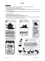
CALIFORNIA
Proposition 65 Warning
Diesel engine exhaust and some of its constituents are known
to the State of California to cause cancer, birth defects, and
other reproductive harm.
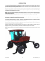
INTRODUCTION
Your new Self-Propelled Windrower is designed to cut and lay in windrows, a wide variety of grain, hay and
specialty crops. Windrowing allows starting the harvest earlier, protects the crop from wind damage, and gives
you more flexibility in scheduling combine time.
The power unit (referred to in this manual as the "tractor"), when coupled with one of the specially designed
draper or auger headers, provides a package which incorporates many features and improvements in design
requested by Owner/Operators like yourself.
NOTE: This manual contains information on the windrower tractor only. It is to be used in conjunction with the
Header Operator's Manual.
CAREFULLY READ BOTH MANUALS TO BECOME FAMILIAR WITH ALL RECOMMENDED
PROCEDURES BEFORE ATTEMPTING TO UNLOAD, ASSEMBLE OR USE THE WINDROWER.
Use the manual as your first source of information about the machine. If you follow the instructions given in
this manual, your Windrower will work well for many years.
The manual contains instructions for "Safety", "Operation", and "Maintenance/Service". In addition "Unloading
and Assembly" information is given towards the back of this book.
Use the Table of Contents and the Index to guide you to specific areas. Study the Table of Contents to
familiarize yourself with how the material is organized.
Keep this manual handy for frequent reference and to pass on to new operators or owners. Call your
Windrower dealer if you need assistance, information, or additional copies of the manuals.
NOTE: Right hand (R/H) and left hand (L/H) designations are determined from the operator's position, facing
forward.
Form # 46584
1
Issue 11/06 Web Rev_01
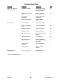
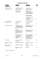
TABLE OF CONTENTS
PAGE
INTRODUCTION...........................................................................................................................................1
SERIAL NUMBER LOCATIONS ...................................................................................................................5
SAFETY
Safety Alert Symbol ................................................................................................................................6
Signal Words ..........................................................................................................................................6
Safety Signs ........................................................................................................................................7,8
General Farm Safety .........................................................................................................................9,10
SPECIFICATIONS
Tractor ..................................................................................................................................................11
Engines.................................................................................................................................................12
Hardware Torque Specifications ..........................................................................................................13
Hydraulic Fitting Torque Specifications ................................................................................................14
OPERATOR'S STATION
Symbol Definitions..........................................................................................................................15, 16
Mac Monitor ....................................................................................................................................17, 18
Operator Presence System ..................................................................................................................19
Gauges .................................................................................................................................................19
Speedometer ........................................................................................................................................19
Ignition Switch ......................................................................................................................................20
Lights ....................................................................................................................................................20
Cab Temperature Controls ...................................................................................................................21
Windshield Wiper Control .....................................................................................................................21
Windrower Controls ..............................................................................................................................22
Header Controls ............................................................................................................................23 - 25
Seat Belts .............................................................................................................................................25
Seat Adjustments .................................................................................................................................26
Operator Amenities...............................................................................................................................27
OPERATION
Your Responsibilities as an Owner/Operator .......................................................................................28
To the New Operator ............................................................................................................................28
Break-In Period.....................................................................................................................................29
Pre-Starting Checks: Annual ................................................................................................................30
Pre-Starting Checks: Daily ...................................................................................................................31
Start-Up Procedure.........................................................................................................................32, 33
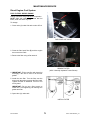
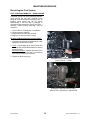
Driving the Windrower
Safety.............................................................................................................................................34
To Drive Forward ...........................................................................................................................35
To Drive Rearward.........................................................................................................................36
Making a Spin Turn........................................................................................................................37
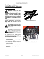
Stopping Procedure
To Stop Windrower ........................................................................................................................38
To Stop Engine ..............................................................................................................................38
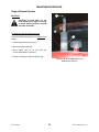
Leaving the Windrower.........................................................................................................................39
Emergency Exit..............................................................................................................................39
Attaching the Header.....................................................................................................................40 - 42
Adding Rear Weight .......................................................................................................................43, 44
Detaching the Header.....................................................................................................................45, 46
Operating the Header ...........................................................................................................................47
Header Lift Cylinder Stops....................................................................................................................47
Header Angle........................................................................................................................................48
Header Levelling...................................................................................................................................49
Header Flotation ...................................................................................................................................50
Transporting the Windrower
Driving on Roads ...........................................................................................................................51
Form # 46584
2
Issue 11/06 Web Rev_01
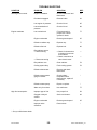
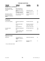
TABLE OF CONTENTS
OPERATION
PAGE
Transporting the Windrower (continued)
Towing With a Trailer ...............................................................................................................52, 53
Towing without a Trailer...........................................................................................................54, 55
Storage Procedure ......................................................................................................................................56
MAINTENANCE/SERVICE
Service Procedures ............................................................................................................................57
Seat Belt Inspection and Maintenance .............................................................................................58
Operator Presence System................................................................................................................58
R/H Step Ladder Use & Storage ........................................................................................................58
Fuels, Fluids and Lubricants
Diesel Fuel .....................................................................................................................................59
Engine Coolant ..............................................................................................................................59
Grease ...........................................................................................................................................59
Hydraulic Oil...................................................................................................................................59
Engine Oil ......................................................................................................................................60
Bevel Gear Box Lubricant ..............................................................................................................60
Power Wheel Gear Lubricant.........................................................................................................60
Storing Lubricants ..........................................................................................................................60
System Capacities .........................................................................................................................60
Greasing the Windrower Tractor ..................................................................................................61 - 63
Diesel Engine
Cummins Barring Tool ...................................................................................................................64
Opening and Closing Hood............................................................................................................64
Lubricating Oil ..........................................................................................................................65, 66
Belts ...............................................................................................................................................66
Engine Speed: Throttle Rod Adjustment (Naturally Aspirated)......................................................67
Engine Speed: Throttle Rod Adjustment (Turbo)...........................................................................68
Valve Tappet Clearance ................................................................................................................68
General Engine Inspection.............................................................................................................68
Diesel Engine Air Intake System: Air Cleaner.............................................................................69, 70
Diesel Engine Fuel System
Storing Fuel....................................................................................................................................71
Refuelling Windrower.....................................................................................................................71
Fuel Tank Venting..........................................................................................................................71
Fuel Sediment Bowl .......................................................................................................................72
Fuel Water Separator.....................................................................................................................72
Fuel Filters .....................................................................................................................................73
Fuel System Air Removal ........................................................................................................74, 75
Engine Exhaust System: Muffler ........................................................................................................76
Engine Cooling System
Coolant Level .................................................................................................................................77
Radiator Cap..................................................................................................................................77
Anti-Freeze Concentration .............................................................................................................77
Changing Coolant ..........................................................................................................................78
Screens and Coolers .....................................................................................................................79
Electrical System
Battery.....................................................................................................................................80 - 82
Preventing Alternator and Regulator Damage ...............................................................................83
Lights and Bulbs .....................................................................................................................84 - 87
Circuit Breakers .............................................................................................................................88
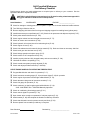
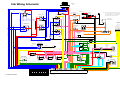
Electrical Schematics.................................................................................................... back of book
Hydraulic System
Safety.............................................................................................................................................89
Hydraulic Oil Cooler .......................................................................................................................89
Hydraulic Oil & Filters ..............................................................................................................89, 90
Form # 46584
3
Issue 11/06 Web Rev_01
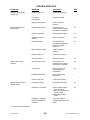
TABLE OF CONTENTS
PAGE
MAINTENANCE/SERVICE (continued)
Hydraulic System: Header & Reel Lift
Cylinder Control Valve Relief Pressure .........................................................................................91
Header & Reel Lift Hydraulic Schematic....................................................................... back of book
Header Drive: Hydraulics
Flow Control Block .........................................................................................................................92
Header Drive Relief Pressure ........................................................................................................92
Header Drive Hydraulic Schematic ............................................................................... back of book
Header Drive
Bevel Gear Box Lubricant ..............................................................................................................93
Header Drive Belt...........................................................................................................................93
Header Drive Belt Pulley Alignment.........................................................................................94, 95
Header Drive Belt Guides & Pulley Shield...............................................................................95, 96
Traction Drive: Hydraulics
Transmission Oil Pressure.............................................................................................................97
Charge Pump Pressure .................................................................................................................97
Traction Drive Hydraulic Schematic.............................................................................. back of book
Traction Drive: Neutral Lock and Steering
Checks ..................................................................................................................................98 - 100
Troubleshooting ...........................................................................................................................101
Neutral Set-Up Procedure....................................................................................................102, 103
Traction Drive:
Ground Speed Lever Friction Device...........................................................................................104
Wheels and Tires ................................................................................................................105 - 107
Park Brake (models 9250/9350, 4940/4950, 2940/2950, 8140/8150) .........................................108
Park Brake (models 9352, 4952, 2952, 8152) .............................................................................109
Cab Air System..........................................................................................................................110 - 112
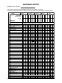
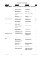
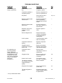
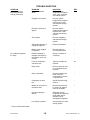
MAINTENANCE SCHEDULE ...........................................................................................................113, 114
MAINTENANCE RECORD ...............................................................................................................115, 116
TROUBLE SHOOTING
Cab Air System..........................................................................................................................117 - 120
Engine .......................................................................................................................................120 - 125
Electrical .....................................................................................................................................125, 126
Traction Drive System ...............................................................................................................126 - 128
Steering and Ground Speed Controls ................................................................................................128
Header Hydraulics ..............................................................................................................................129
Header Drive .............................................................................................................................129 - 131
Park Brake..........................................................................................................................................131
Operator's Seat...................................................................................................................................131
OPTIONS AND ATTACHMENTS .............................................................................................................132
UNLOADING .....................................................................................................................................133, 134
ASSEMBLY
Tires...........................................................................................................................................135 - 137
Battery ........................................................................................................................................138, 139
Adjustments & Checks .......................................................................................................................139
Preparing for Harvest Headers..................................................................................................140 - 143
Radio & Two-Way Radio Installation ..........................................................................................144, 145
Tool Box .............................................................................................................................................145
Swath Roller Installation .....................................................................................................................146
INDEX ...........................................................................................................................................147 – 149
ELECTRICAL & HYDRAULIC SCHEMATICS ..........................................................................................150
Form # 46584
4
Issue 11/06 Web Rev_01
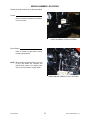
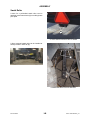
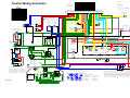
SERIAL NUMBER LOCATIONS
Record the serial numbers in the space provided.
Tractor:
Plate is located on left side of main frame,
near rear corner.
TRACTOR SERIAL PLATE LOCATION
Diesel Engine:
Plate is located on right side of block,
beside injection pump.
NOTE: When ordering parts and service, be sure
to give your dealer the complete and
proper serial number. For engine parts,
see your local Cummins engine dealer.
DIESEL ENGINE SERIAL PLATE LOCATION
Form # 46584
5
Issue 11/06 Web Rev_01
SAFETY
SAFETY ALERT SYMBOL
This safety alert symbol indicates important safety messages in this
manual and on safety signs on the header.
This symbol means:
ATTENTION !
BECOME ALERT !
YOUR SAFETY IS INVOLVED !
Carefully read and follow the safety message accompanying this symbol.
Why is SAFETY important to you?
3 BIG REASONS
· ACCIDENTS DISABLE AND KILL
· ACCIDENTS COST
· ACCIDENTS CAN BE AVOIDED
SIGNAL WORDS
Note the use of the signal words DANGER, WARNING, and CAUTION with safety messages. The appropriate
signal word for each message has been selected using the following guidelines:
DANGER – Indicates an imminently hazardous situation that, if not avoided, will result in death or
serious injury.
WARNING – Indicates a potentially hazardous situation that, if not avoided, could result in death or
serious injury. It is also used to alert against unsafe practices.
CAUTION – Indicates a potentially hazardous situation that, if not avoided, may result in minor or
moderate injury. It is also used as a reminder of good safety practices.
Form # 46584
6
Issue 11/06 Web Rev_01
SAFETY
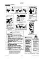
SAFETY SIGNS
•
•
•
•
•
The safety signs reproduced below appear on the windrower at the locations listed.
Keep safety signs clear and legible at all times.
Replace safety signs that are missing or become illegible.
If original parts on which a safety sign was installed are replaced, be sure the repair part also bears the
current safety sign.
Safety signs are available from your Dealer Parts Department. The part number is printed in the lower R/H
corner of each safety sign.
To install safety signs:
1. Be sure the installation area is clean and dry.
2. Decide on the exact position before you remove the backing paper.
3. Remove the smaller portion of the split backing paper.
4. Place the sign in position and slowly peel back the remaining paper, smoothing the sign as it is applied.
5. Small air pockets can be smoothed out or pricked with a pin.
Form # 46584
7
Issue 11/06 Web Rev_01
SAFETY
SAFETY SIGNS (continued)
Form # 46584
8
Issue 11/06 Web Rev_01
SAFETY
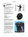
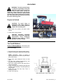
GENERAL SAFETY
The following are general farm safety
precautions that should be part of
your operating procedure for all types
of machinery.
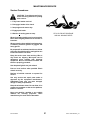
1. Protect yourself.
When assembling, operating and servicing
machinery, wear all the protective clothing
and personal safety devices that COULD be
necessary for the job at hand. Don't take
chances.
·
·
·
·
·
·
·
You may need:
a hard hat.
protective shoes with slip resistant soles.
protective glasses or goggles.
heavy gloves.
wet weather gear.
respirator or filter mask.
hearing protection. Be aware that prolonged
exposure to loud noise can cause
impairment or loss of hearing. Wearing a
suitable hearing protective device such as
ear muffs (A) or ear plugs (B) protects
against objectionable or loud noises.
PROTECT YOURSELF
PROTECT AGAINST NOISE
2. Provide a first-aid kit for use in case of
emergencies.
3. Keep a fire extinguisher on the machine. Be
sure the extinguisher is properly maintained
and be familiar with its proper use.
4. Keep young children away from machinery
at all times.
5. Be aware that accidents often happen when
the operator is tired or in a hurry to get
finished. Take the time to consider the
safest way. Never ignore warning signs of
fatigue.
Form # 46584
BE PREPARED FOR EMERGENCIES
9
Issue 11/06 Web Rev_01
SAFETY
GENERAL SAFETY (continued)
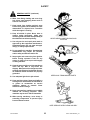
6. Wear close-fitting clothing and cover long
hair. Never wear dangling items such as
scarves or bracelets.
7. Keep hands, feet, clothing and hair away
from moving parts. Never attempt to clear
obstructions or objects from a machine
while the engine is running.
8. Keep all shields in place. Never alter or
remove safety equipment. Make sure
driveline guards can rotate independently of
the shaft and can telescope freely.
NEVER WEAR LOOSE OR DANGLING
CLOTHES
9. Use only service and repair parts made or
approved by the equipment manufacturer.
Substituted parts may not meet strength,
design, or safety requirements.
10. Do not modify the machine. Unauthorized
modifications may impair the function
and/or safety and affect machine life.
11. Stop engine and remove key from ignition
before leaving operator's seat for any
reason. A child or even a pet could engage
an idling machine.
12. Keep the area used for servicing machinery
clean and dry. Wet or oily floors are
slippery. Wet spots can be dangerous when
working with electrical equipment. Be sure
all electrical outlets and tools are properly
grounded.
KEEP AWAY FROM MOVING PARTS
13. Use adequate light for the job at hand.
14. Keep machinery clean. Straw and chaff on a
hot engine are a fire hazard. Do not allow oil
or grease to accumulate on service
platforms, ladders or controls. Clean
machines before storage.
15. Never use gasoline, naphtha or any volatile
material for cleaning purposes. These
materials may be toxic and/or flammable.
16. When storing machinery, cover sharp or
extending components to prevent injury
from accidental contact.
KEEP SERVICE AREA CLEAN AND DRY
Form # 46584
10
Issue 11/06 Web Rev_01
SPECIFICATIONS
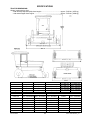
TRACTOR DIMENSIONS:
Weight (varies with tire size):
- with naturally-aspirated (N/A) diesel engine ...............................................approx. 7225 lbs. (3275 kg)
- with turbocharged diesel engine .................................................................approx. 7250 lbs. (3290 kg)
Drive Tire
21.5L - 16.1
14.9 - 24
500-70R24
Tread Width A
118.1" (3000 mm)
118.5" (3010 mm)
117" (2972 mm)
Front Width B
139.5” (3543 mm)
133.5” (3390 mm)
Clearance C
Height D
38.3” (972 mm)
122.5” (3112 mm)
42.1” (1070 mm)
126.3” (3210 mm)
Drive Tire
21.5L – 16.1
Caster Tire
9.5L – 14 Form/Fork 16.5L - 16.1 Forked
540 - 65R24
117" (2972 mm)
560 - 65D24
117" (2972 mm)
136” (3455 mm)
137” (3480 mm)
139.3” (3538 mm)
43.4” (1102 mm)
42.1” (1070 mm)
43.0” (1092 mm)
127.6” (3240 mm)
126.3” (3210 mm)
127.2” (3230 mm)
Wheel Base E
112.8" (2864 mm)
119.8" (3040 mm)
14.9 – 24, 500 – 70R24, 540 – 65R24, OR 560 – 65D24
16.5L - 16.1
11.0 – 16 Forked
7.5L – 16 Formed
Forked
118.3" (3005 mm)
118.3" (3005 mm)
114.4" (2906 mm)
Wheel Base F
127.7" (3244 mm)
134.7" (3420 mm)
133.3" (3385 mm)
133.3" (3385 mm)
129.4” (3287 mm)
Rear Width G
135.2" (3435 mm)
142.3" (3615 mm)
142.3" (3615 mm)
142.3" (3615 mm)
–
Dim. H (Formed)
8.9” (225 mm)
–
–
–
–
Rear Width J
133.7” (3396 mm)
–
–
–
–
Rear Width K
–
–
–
–
143” (3632 mm)
Rear Width L
–
–
–
–
130.1” (3304 mm)
Form # 46584
11
Issue 11/06 Web Rev_01
SPECIFICATIONS
TRANSMISSION:
Type ............................................................................................................................................ Hydrostatic
Displacement..................................................................................................................3.0 cu.in. (49.16 cc)
Fluid......................................................See "Fuels, Fluids and Lubricants" in Maintenance/Service section
FINAL DRIVE:
Type .............................................................................................................................Planetary Gear Drive
Ratio: Models 9250/9350, 4940/4950, 2940/2950, 8140/8150................................................... 28.37 to 1
Models 9352, 4952, 2952, 8152....................................................................................... 37.89 to 1
Lubricant...............................................See "Fuels, Fluids and Lubricants" in Maintenance/Service section
SPEED RANGE:
Single Speed Forward: Models 9250/4940/2940/8140 ..................................................... 0 - 12 mph (19 km/h)
Dual Speed Fwd.: Models 9350/4950/2950/8150 ..... Field: 0 - 10 mph (16 km/h) Road: 0 – 16 mph (26 km/h)
Dual Speed Fwd.: Models 9352/4952/2952/8152 . Field: 0 - 9 mph (14.5 km/h) Road: 0 – 15.5 mph (25 km/h)
Reverse .......................................................................................................................... 0 - 6 mph (10 km/h)
HEADER DRIVE:
Mechanical ............................................................................ 4-A section belt, electric over hydraulic clutch
Hydraulic ............................. 2 circuits, clutch activated, w/ independent flow controls (3 - 9 US gpm each)
CYLINDER CONTROL VALVE: Type .....................................................Cartridge valves in manifold block
ELECTRICAL:
Battery Requirement .................................................................. 12 Volt, minimum 640 CCA @ 0°F (-18°C)
Alternator......................................................................................................................................... 105 Amp
Breakers:
Lights (manual re-set)....................................................................................................... 50 Amp
Main (all functions except lights, manual re-set) .............................................................. 50 Amp
Air Conditioning and Seat Suspension Switch ................................................................. 25 Amp
Header Controls, Operator Presence System .................................................................. 10 Amp
Instruments, Radio and Screen Motors .............................................................................. 6 Amp
Wiper, Interior Light, Radio Memory and Auxiliary Power Points ....................................... 6 Amp
Fuse:
Cigar Lighter ..................................................................................................................... 20 Amp
AIR CONDITIONING:
Cooling Capacity ............................................................................................................. 24,000 B.T.U./hour
Compressor..................................................................................................................9.5 cu. in./rev., rotary
PARK BRAKE: ....................................................................................................Drum type, lever activated
DRIVE TIRES:
Models 9250/9350, 4940/4950, 2940/2950,
8140/8150
21.5L - 16.1 I3 Bar Tread
21.5L - 16.1 R3 Turf & Field or Softrac II
Models 9352, 4952, 2952, 8152
14.9 – 24 R4 Bar Tread – Sprayer Application Only
560 – 65D24 Softrac II Turf Tread
500 – 70R24 Radial - Bar Tread
540 – 65R24 Radial – Deep Bar Tread
NOTE: Pressures below are for a fully loaded header. If hay conditioner is removed, or a bat reel replaces a
pick-up reel, reduce pressures by 2 psi (14 kPa).
Drive Tire Inflation Pressures
Header Model
Header Size
21.5L - 16.1
14.9 - 24
500 - 70R24
540- 65R24 or 560-65D24
912, 922, 933
All
19 psi (132 kPa)
33 psi (228 kPa)
19 psi (132kPa)
18 psi (125 kPa)
962
All
21 psi (145 kPa)
36 psi (248 kPa)
21 psi (145 kPa)
20 psi (138 kPa)
972
12 - 21
19 psi (132 kPa)
33 psi (228 kPa)
19 psi (132kPa)
18 psi (125 kPa)
972/Sprayer
25 - 36
25 psi (172 kPa)
42 psi (289 kPa)
24 psi (165 kPa)
22 psi (151 kPa)
TAIL WHEEL TIRES: Inflation Pressure
9.5L - 14 I1 Rib Implement10 psi (70 kPa)
16.5L - 16.1 I1 8 ply Rib Implement10 psi (70 kPa)
11 – 16 F-2M 8 Ply Rib Implement10 psi (70 kPa)
7.5 – 16 6 ply Single Rib TT, F-119 psi (132 kPa)
CAPACITIES: See "System Capacities" in Maintenance/Service section.
Form # 46584
12
Issue 11/06 Web Rev_01
SPECIFICATIONS
DIESEL ENGINES:
Type ...................................................................................................... Cummins B 4.5NA, 4 Cylinder, 4-stroke cycle - Turbocharged
Displacement ..............................................................................................................................................................275 cu. in. (4.5 L)
Power: ........................................................................................................................................................ 110 hp (82kW) @ 2500 rpm
Bore ........................................................................................................................................................................... 4.02 in. (102 mm)
Stroke......................................................................................................................................................................... 5.42 in. (138 mm)
Compression Ratio ...................................................................................................................................................................18.0 to 1
Oil Type.........................................................................................See "Fuels, Fluids and Lubricants" in Maintenance/Service section
Oil Pressure: @ 2300 rpm ....................................................................................................................... 30 to 60 psi (210 to 415 kPa)
@ minimum (idle rpm) ........................................................................................................................... 13 psi (90 kPa)
Firing Order (No.1 cylinder at fan end).................................................................................................................................. 1 - 3 - 4 - 2
Engine Speed: Turbocharged version ......................................................................................................................... 2395 - 2495 rpm
Engine Idle Speed................................................................................................................................................................... 1100 rpm
Rocker Arm-to-Valve Clearance: Exhaust ............................................................................................................0.020 inch (0.50 mm)
Intake................................................................................................................0.010 inch (0.25 mm)
IMPORTANT: Rocker arm-to-valve clearance adjustments must be made with the engine not running.
Thermostat ......................................................................................................................................................................... 180˚F (82˚C)
Fuel ...............................................................................................See "Fuels, Fluids and Lubricants" in Maintenance/Service section
Engine Coolant .............................................................................See "Fuels, Fluids and Lubricants" in Maintenance/Service section
NOTE: Specifications and design are subject to change without notice or obligation to revise units previously sold.
TORQUE SPECIFICATIONS
CHECKING BOLT TORQUE
The tables shown below give correct torque values for various bolts and capscrews. Tighten all bolts to the torques
specified in chart unless otherwise noted throughout this manual. Check tightness of bolts periodically, using bolt torque
chart as a guide. Replace hardware with the same strength bolt.
their head markings.
ENGLISH TORQUE SPECIFICATION
METRIC TORQUE SPECIFICATIONS
NC Bolt Torque*
Bolt
Dia.
"A"
N·m
[lb-ft]
N·m
[lb-ft]
1/4"
12
[9]
15
[11]
SAE 5
Bolt
Dia.
"A"
SAE 8
Bolt Torque*
8.8
10.9
N·m
[lb-ft]
N·m
[lb-ft]
M3
0.5
[.4]
1.8
[1.3]
M4
3
[2.2]
4.5
[3.3]
M5
6
[4]
9
[7]
M6
10
[7]
15
[11]
5/16"
24
[18]
34
[25]
3/8"
43
[32]
56
[41]
7/16"
68
[50]
95
[70]
1/2"
102
[75]
142
[105]
M8
25
[18]
35
[26]
9/16"
149
[110]
202
[149]
M10
50
[37]
70
[52]
5/8"
203
[150]
271
[200]
M12
90
[66]
125
[92]
3/4"
359
[265]
495
[365]
M14
140
[103]
200
[148]
7/8"
569
[420]
813
[600]
M16
225
[166]
310
[229]
1"
867
[640]
1205
[890]
M20
435
[321]
610
[450]
M24
750
[553]
1050
[774]
M30
1495
[1103]
2100
[1550]
M36
2600
[1917]
3675
[2710]
Torque figures indicated above are valid for non-greased or
non-oiled threads and heads unless otherwise specified. Do
not grease or oil bolts or capscrews unless specified in this
manual. When using locking elements, increase torque
values by 5%.
* Torque value for bolts and capscrews are identified by
Form # 46584
13
Issue 11/06 Web Rev_01
TORQUE SPECIFICATIONS
TIGHTENING HYDRAULIC O-RING FITTINGS*
1. Inspect O-ring and seat for dirt or obvious
defects.
2. On angle fittings, back the lock nut off until
washer bottoms out at top of groove.
Thread
Size
(in.)
3. Hand tighten fitting until back-up washer or
washer face (if straight fitting) bottoms on face
and O-ring is seated.
4. Position angle fittings by unscrewing no more
than one turn.
5. Tighten straight fittings to torque shown.
6. Tighten angle fittings to torque shown while
holding body of fitting with a wrench.
*
The torque values shown are based on
lubricated connections as in reassembly.
Nut Size
Across
Flats
(in.)
Torque Value*
Recommended
Turns to Tighten
(after finger
tightening)
N·m
[lb-ft]
Flats
Turns
3/8
1/2
8
[6]
2
1/3
7/16
9/16
12
[9]
2
1/3
1/2
5/8
16
[12]
2
1/3
9/16
11/16
24
[18]
2
1/3
3/4
7/8
46
[34]
2
1/3
7/8
1
62
[46]
1-1/2
1/4
1-1/16
1-1/4
102
[75]
1
1/6
1-3/16
1-3/8
122
[90]
1
1/6
1-5/16
1-1/2
142
[105]
3/4
1/8
1-5/8
1-7/8
190
[140]
3/4
1/8
1-7/8
2-1/8
217
[160]
1/2
1/12
TIGHTENING HYDRAULIC FLARE-TYPE
TUBE FITTINGS*
1. Check flare and flare seat for defects that
might cause leakage.
2. Align tube with fitting before tightening.
Tube
Size
O.D.
(in.)
3. Lubricate connection and hand tighten swivel
nut until snug.
4. To prevent twisting the tube(s), use two
wrenches. Place one wrench on the connector
body and with the second tighten the swivel
nut to the torque shown.
*
The torque values shown are based on
lubricated connections as in reassembly.
Form # 46584
14
Nut Size
Across
Flats
(in.)
Torque Value*
Recommended
Turns to Tighten
(after finger
tightening)
N·m
[lb-ft]
Flats
Turns
3/16
7/16
8
[6]
1
1/6
1/4
9/16
12
[9]
1
1/6
5/16
5/8
16
[12]
1
1/6
3/8
11/16
24
[18]
1
1/6
1/2
7/8
46
[34]
1
1/6
5/8
1
62
[46]
1
1/6
3/4
1-1/4
102
[75]
3/4
1/8
7/8
1-3/8
122
[90]
3/4
1/8
Issue 11/06 Web Rev_01
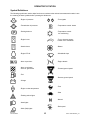
OPERATOR'S STATION
Symbol Definitions
The following symbols are used to depict functions or reactions at the various instruments and controls. Learn
the meaning of these symbols before operating the Windrower.
- Engine oil pressure
- Turn signals
- Transmission oil pressure
- Temperature control: heater
- Parking brake on
- Temperature control:
Air conditioning
- Engine hours
- Turn to increase output:
Heater or air conditioner
- Header hours
- Blower
- Engine R.P.M.
- Windshield wiper
- Area cut per hour
- Engine throttle
- Area cut: subtotal
Area cut: grand total
- Forward ground speed
- Fuel
- Reverse ground speed
- Voltage
- Fast
- Engine coolant temperature
- Slow
- Flashing amber lights
- Neutral
- Head lights
- Reel speed
- Work (field) lights
Form # 46584
15
Issue 11/06 Web Rev_01
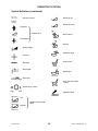
OPERATOR'S STATION
Symbol Definitions (continued)
- Header tilt up
- Conveyor speed
- Header tilt down
- Engaged
- Header drive
- Reel forward
- Disengaged
- Reel aft
- Header height
- Seatback angle
- Increase
- Seat fore-aft
- Decrease
- Reel height
- Seat height
- Deck shift
- Seat fore-aft isolator
lockout
- Speed range control
High
Low
- Cigarette lighter
- On
- Header express down
option
- Bypass
Form # 46584
16
Issue 11/06 Web Rev_01
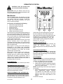
OPERATOR'S STATION
CAUTION: Learn and practice safe
use of controls before operating.
IMPORTANT: See your Dealer if there are any
instrument malfunctions. Operate windrower only if
all instruments work properly.
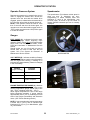
B
Mac-Monitor
D
C
The LCD display allows the operator to monitor
various machine systems, while the warning lights
and audible tones are provided to alert the
operator that continued operation will cause
serious machine damage.
Six Function LCD displays the following:
• tachometer (engine speed) (B)
• cutting rate (area per hour) (C)
• subtotal area (D)
• grand total area (D)
• engine accumulated hours (E)
• header accumulated hours (F)
Select function by momentarily pressing switch (A)
once for each mode change. The function light for
the current selection will flash for 10 seconds. The
other function lights burn steadily during scrolling
to indicate which functions are currently available
at the present engine speed.
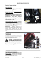
When engine is not running, and key is in the ON
position, subtotal area is the default and
momentarily pressing switch (A) scrolls through
grand total area, engine hours, header hours and
back to subtotal area.
When engine is running at less than 2000 rpm,
tachometer is the default and momentarily
pressing switch (A) scrolls through all six functions.
After 10 seconds in any mode, the monitor
switches back to tachometer.
When engine speed is greater than 2000 rpm,
tachometer is the default and momentarily
pressing switch (A) scrolls through cutting rate,
subtotal area and back to tachometer. Tach or
cutting rate will remain displayed until switch is
pressed, while subtotal area will revert back to
tachometer after 10 seconds
E
F
Grand total cut area shows total area cut over
life of the windrower. After 9999, display will
flash back and forth between thousand units and
hundred units. For example, 53286 would be
displayed by flashing between 53_ and _286,
while 573902 would be displayed by flashing
between 573_ and _902.
ENGINE HOUR METER (E):
Accumulates time that the engine is running. The
display will alternate between 4 digits
(representing hours accumulated) and tenths of an
hour.
HEADER HOUR METER (F):
Accumulates time that the header is engaged with
the engine running. The display will alternate
between 4 digits (representing hours accumulated)
and tenths of an hour.
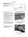
PROGRAMMING
To ensure cutting rate, cut area and speedometer
display correctly, program the monitor for units of
measure, cut width and tire size as follows:
1. Turn the ignition key to the off position
2. Depress and hold switch (A) while turning the
key to the on position to enter programming
mode, then release switch.
NOTE: Programming mode works only if engine is
not running.
3. Momentarily press switch (A) to scroll through
these programming modes: “ENG/SI”,
“CUT WIDTH” and “TIRE SIZE”. Do not hold
switch for more than 5 seconds. The active
selection within each mode flashes on the
display.
Continued next page.
TACHOMETER (B):
Indicates engine speed in revolutions per minute.
CUTTING RATE (Area per hour) (C):
Displays in either acres or hectares. Calculates
rate of crop cut when header is engaged and
engine rpm exceeds 2000 rpm based on ground
speed and programmed cut width.
SUBTOTAL/GRAND TOTAL CUT AREA (D):
Displays in either acres or hectares. Subtotal cut
area will display first. This shows area cut since
last reset. When in this mode hold the button for
5 seconds to reset the subtotal to zero.
Form # 46584
A
17
Issue 11/06 Web Rev_01
OPERATOR'S STATION
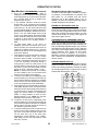
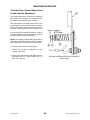
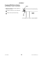
Mac-Monitor Machine Warning System:
Consists of individual lights to indicate low engine
oil pressure, low transmission oil pressure and
park brake on. An audible tone will sound
whenever one of the indicator lights is on. In
addition, the tone will sound when a high engine
coolant temperature is indicated.
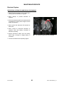
Mac-Monitor: PROGRAMMING (continued)
4.
Once the desired programming mode is
displayed, enter the selection mode by pressing
and holding switch (A) for more than 5 seconds.
(At 5 seconds there will be an audible tone.
Release switch at tone.)
5. In the “ENG/SI” selection mode the monitor
shows “ENG” or “SI”, whichever unit of measure
is active. To scroll between the two, momentarily
push switch (A). “SI” will cause cutting rate and
cut area totals to display in hectares. As well, the
speedometer will display in kilometers per hour.
When in “SI”, the small triangle at the top left
corner of the digital display will be illuminated.
“ENG” will cause cutting rate and cut area totals
to display in acres and the speedometer to
display in miles per hour. Shipping Position =
ENG.
6. To select either “ENG” or “SI” once it is
displayed, press and hold switch (A) for more
than 5 seconds. (At 5 seconds there will be an
audible tone. Release switch at tone.) This also
advances the monitor to the next programming
mode (CUT WIDTH).
7. Press switch (A) for 5 seconds again to enter the
“CUT WIDTH” selection mode. The monitor
shows the active cut width. To scroll through the
cut widths, momentarily press switch (A) to scroll
in 0.5 foot increasing increments through a
cutting range of 10.0 to 37.0 feet (3.05 to 11.28
meters). Display in feet will have an “F” following
the width, e.g. 24.5 feet cutting width would be
shown as “24.5F”. Shipping Position = 10.0F
NOTE: To advance the cut width in increments
of 5 feet instead of 0.5, turn the header drive
switch on and off again (see page 23).
8. To select a cut width once it is displayed, press
and hold switch (A) for more than 5 seconds. (At
5 seconds there will be an audible tone. Release
switch at tone.) This also advances the monitor
to the next programming mode (TIRE SIZE).
9. Press switch (A) for 5 seconds again to enter the
“TIRE SIZE” selection mode. The monitor shows
the active tire size. Momentarily press switch (A)
to scroll through tire options. This selection will
trigger the correct readout for speedometer,
based on rolling diameter of each tire size.
Shipping Position = 21.5. NOTE: For units with
500 series tires, select the “500” option.
10. To select a tire size once it is displayed, press
and hold switch (A) for more than 5 seconds. (At
5 seconds there will be an audible tone. Release
switch at tone.) This also returns the monitor to
the “ENG/SI” programming mode.
11. To save the settings into memory and return the
monitor into the normal working mode, turn the
key to the “off” position and back on again. This
can be done from any of the three main
programming modes (ENG/SI, CUT WIDTH,
TIRE SIZE), but not from the selection mode
within any of these.
Form # 46584
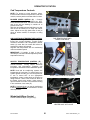
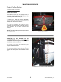
ENGINE OIL PRESSURE LIGHT (G):
Both light and tone will be activated when ignition
switch is turned ON if engine oil pressure is below
11 psi (75 kPa). If light and tone stay on for more
than a few seconds after engine starts, or if they
activate while engine is running, shut engine off
and check engine oil level.
TRANSMISSION OIL PRESSURE LIGHT (H):
Both light and tone will be activated when ignition
switch is turned ON if transmission oil pressure is
below 150 psi (1035 kPa) for Turbo or 40 psi (275
kPa) for Naturally Aspirated engine. Do not drive
the windrower until light and tone go off. If light and
tone stay on after engine starts, or if they activate
during operation, shut engine off and check
hydraulic oil level at reservoir. If oil level is
adequate, measure supercharge relief pressure.
See "Traction Drive: Hydraulics" in Maintenance/
Service section.
PARKING BRAKE LIGHT (J):
Both light and tone will be activated when ignition
switch is turned to ON as a reminder to release
brake before driving windrower. Release of brake
de-activates light and tone. Light and tone will not
activate with transmission in neutral.
G
H
J
SI
INDICATOR
A
18
Issue 11/06 Web Rev_01
OPERATOR'S STATION
Operator Presence System
Speedometer
Requires the operator to be seated in the seat in
order to engage the header drive. Should the
operator leave the seat with the header drive
engaged, power is maintained to the header drive
for 5 seconds, after which the header is shut off.
NOTE: If the operator leaves the seat for more
than 5 seconds and then sits down again, the
operator must move the header engage switch to
“OFF” position and back to the “ON” position again
to restart the header.
The speedometer (D) indicates vehicle speed in
miles per hour or kilometres per hour.
Programming to switch between miles and
kilometres is done at the Mac-Monitor (see
previous page). An arrow in top left corner of
display indicates kilometres per hour is currently
displayed.
D
Gauges
FUEL GAUGE (A) - Indicates fuel level in tank.
Check fuel gauge before beginning day's
operation. Stop to refuel before fuel gauge reaches
empty mark. Use fuel specified under "Fuels,
Fluids and Lubricants" in Maintenance/ Service
section.
Should engine run out of fuel and not start in
several tries, air must be bled from the fuel
system. See "Fuel System Air Removal" in
Maintenance /Service section.
SPEEDOMETER
VOLT METER (B) - Indicates condition of battery
and alternator. With key switch in the ON position
and the engine NOT running, a reading of 12
indicates fully charged battery. Watch for changes
in the volt reading:
Indicated
Condition
Reading
(engine running)
14
over 16
under 12
A
normal
B
regulator misadjusted
alternator not working or
regulator misadjusted
C
ENGINE TEMPERATURE GAUGE (C) - Monitors
the temperature of engine coolant. With engine
running, temperature gauge should read in the
180° - 225°F operating range (82° - 107°C).
Allow engine temperature to rise to this range
before beginning operation. If gauge reaches
approximately 225°F (107°C) a warning tone will
sound. Stop engine immediately and determine
cause. (See Trouble Shooting section.)
GAUGES
NOTE: If a tone sounds when engine temperature
is below 225°F (107°C) and no indicator light
illuminates [(G), (H) or (J) on Mac-Monitor, page
18], check bulbs.
Form # 46584
19
Issue 11/06 Web Rev_01
OPERATOR'S STATION
Ignition Switch
A
The ignition switch (A) has three positions; OFF,
RUN and START.
The furthest counter-clockwise position of the key
is OFF. Turn key fully clockwise to START.
Holding key in this position will cause engine to
crank.
Release of key will return to the vertical RUN
position.
C
B
Lights
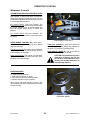
LIGHT SWITCH (B) - The light switch has four
positions:
IGNITION SWITCH AND LIGHTS
1. OFF - Furthest counter-clockwise position. To
turn off all lamps.
2. FLASHER - To turn on flashing amber lamps
and red tail lamps. (For use when windrower is
being hauled by a towing vehicle.)
D
3. ROAD - To turn on head lamps, flashing amber
lamps and red tail lamp. (For driving on
roadways.)
4. FIELD - To turn on head lamps and field lamps.
For field use ONLY.
CAUTION: When operating on a
roadway, switch to the ROAD
position. Never use field lamps or
any lights which might confuse other
drivers. Always use flashing amber lamps
when driving or hauling on roadways, unless
prohibited by law.
TURN INDICATORS
TURN SIGNAL SWITCH (C) - When operating
windrower on a roadway, use turn signals as you
would in a car or truck.
Turn signals will work with flashers on or off.
Moving switch to left or right will flash turning side
lamps with other side steady. An audible signal
(beeper) will sound when turn signal switch is
activated.
Turn indicators (D) are located on headliner.
E
DOME LIGHT - RIGHT REAR CORNER
NOTE: Be sure to return switch (C) to center
position after turning.
F
DOME LIGHT (E) - Pushing button on dome light
turns light ON and OFF
REAR VIEW MIRRORS (F) - Adjust mirrors for
best view.
REAR VIEW MIRRORS
Form # 46584
20
Issue 11/06 Web Rev_01
OPERATOR'S STATION
Cab Temperature Controls
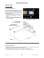
NOTE: For access to circuit breakers, relays,
fuses and other electrical components in cab side
console, remove panel on window side of console.
F
BLOWER SPEED SWITCH (A) - Controls
operation of blower. Four positions are: OFF,
LOW, MEDIUM and HIGH. The blower recirculates
cab air as well as drawing in outside air to
pressurize the cab.
With door and window closed and blower on, dust
and dirt will be filtered out to keep cab interior
clean. Adjust louvers (B) (both sides of cab) to
direct air where needed, for example, to defog
window.
D
AIR CONDITIONING TEMPERATURE CONTROL
(D) - Air conditioning is OFF when control (D) is
turned fully counter-clockwise. Turning control
clockwise decreases cab temperature. Blower
switch (A) must also be turned ON before air
conditioning system will operate.
Regulate cab temperature with air conditioning
control and blower speed.
A
E
CAB TEMPERATURE AND
WIPER CONTROLS
IMPORTANT: If humidity is high it may be
necessary to run blower at HIGH speed to prevent
evaporator freeze up.
B
HEATER TEMPERATURE CONTROL (E) Heater is off when control (E) is turned fully
counter-clockwise. Turning control clockwise
increases cab temperature. Regulate cab
temperature with heater control and blower speed.
B
NOTE: Heat and air conditioning systems are
independent of each other. To avoid working one
system against the other, be sure the system not
in use is turned OFF at the appropriate
temperature control, unless both are required to
defog windows. There is also a shut-off valve for
the heater circuit at the engine. Valve must be
open for heater to function. For maximum cooling
in hot conditions, close valve (G).
DIRECT AIR FLOW WITH LOUVERS
G
NOTE: If windows fog up, run the air conditioning
to dehumidify the cab air, plus the heater to control
cab temperature.
Windshield Wiper Control
Control windshield wiper using knob (F).
HEATER SHUT-OFF VALVE
Form # 46584
21
Issue 11/06 Web Rev_01
OPERATOR'S STATION
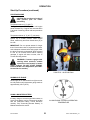
Windrower Controls
VARIABLE GROUND SPEED CONTROL LEVER
(A) Controls windrower direction of movement and
rate of speed. A neutral start switch prevents the
starter from engaging unless this lever is in the
neutral detent as shown and the steering is locked
in the straight-ahead position.
B
C
For forward motion: Push lever forward. The
further the lever is moved from neutral the faster
the speed. Release lever at desired speed and
lever will engage friction device to secure the
position.
For reverse motion: Pull lever rearward. The
further the lever is moved from neutral the faster
the speed.
A
D
WINDROWER CONTROLS
SPEED-RANGE CONTROL (B) (Turbo units) Shifts the transmission to FIELD (Low) or ROAD
(High) speed range.
THROTTLE LEVER (C) - Push lever forward to
increase engine speed (RPM) and rearward to
decrease. Full forward is operating RPM.
Field Speed Range: This setting is for windrower
operating speeds (0 - 10 mph [16 km/h]). Steering
is less sensitive in this range.
PARK BRAKE LEVER (D) - Pull up on lever to
engage brake. Push down to release.
Road Speed Range: This setting is for transport
speeds (0 to 16 mph [26 km/h]). Steering is more
sensitive in this speed range.
CAUTION: Use park brake only when
windrower is stopped. Do not use
park brake to slow windrower when
moving. Use variable speed lever to
slow and stop machine.
STEERING WHEEL
To adjust steering wheel tilt:
1. Push and hold handle (F) down.
2. Move steering wheel to desired position.
3. Release handle to lock the position.
When exiting cab, push handle (F) down. This
returns steering wheel to upright position for easier
exit and re-entry.
F
STEERING WHEEL
Form # 46584
22
Issue 11/06 Web Rev_01
OPERATOR'S STATION
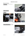
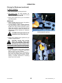
Header Controls
NOTE: Some of these controls are not used
for all types of headers. Some are optional
equipment and may not be present in your unit.
For others, while the switch may be installed, it
will be non-functional for certain headers.
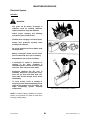
HEADER DRIVE SWITCH (A) - Lift the guard to
expose toggle switch. Push toggle switch forward
to engage all header mechanical and hydraulic
drives. Push guard down to disengage drives.
Starter will not engage if switch is in the engaged
position.
NOTE: Always move throttle lever back to idle
before engaging header drives. Do not engage
with engine at full RPM.
CONVEYOR SPEED CONTROL (B) - Turn knob
clockwise to increase conveyor speed and
counter-clockwise to decrease. Speed range is:
940 Series Headers, Auger speed: 175 - 500 RPM
960/970 Series Headers, Draper speed:
170 to 500 ft/min (50 - 155 m/min)
D
A
B
C
HEADER DRIVE / CONVEYOR SPEED /
REEL SPEED / DECK SHIFT CONTROLS
REEL SPEED CONTROL (C) - Turn knob
clockwise to increase reel speed and counterclockwise to decrease. Speed range is:
920 Series Headers: 30 to 75 RPM
930 Series Headers: 30 to 69 RPM
940/960/970 Series Headers: 20 to 60 RPM
NOTE: 920/930 Series Headers – For these
headers, both controls (B) and (C) affect reel
speed. Set conveyor speed knob (B) to "10" and
adjust reel speed knob (C) to obtain desired reel
speed.
DECK SHIFT SWITCH (D) – Press left side of
rocker switch to shift decks to the left and reverse
draper travel. Press right side of switch to shift
decks to the right and reverse draper travel. For
center delivery, move rocker to center position.
Form # 46584
23
Issue 11/06 Web Rev_01
OPERATOR'S STATION
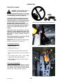
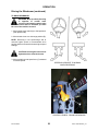
Header Controls (continued)
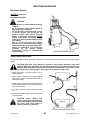
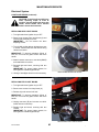
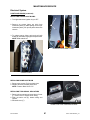
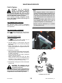
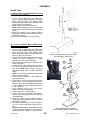
REEL HEIGHT SWITCH (E) - Press top of switch
to raise reel and bottom to lower. Hold switch until
reel reaches desired position.
NOTE: For Auger Headers with Hay Conditioners
equipped with Hydraulic Roll Opener cylinders,
switch (E) controls the operation of these
cylinders.
E
H
K
HEADER HEIGHT SWITCH (F) - Press top of
switch to raise header and bottom to lower. Hold
switch until header reaches desired position. (See
"Cut Height Indicator").
J
F
NOTE: Handle may be rotated on lever to allow
the operator to position switches (E) and (F) for
maximum comfort. To adjust, loosen setscrews on
back of handle.
L
REEL & HEADER HEIGHT SWITCHES
REEL FORE-AFT & HEADER TILT CONTROLS
IMPORTANT: Do not continue pressing
switches (E) or (F) after header or reel travel is
complete. If switch is held for a long period of
time, damage may occur due to overheating
electrical solenoids and/or over-heating
hydraulic oil, which is pumped through relief
valve.
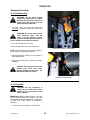
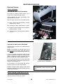
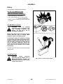
HEADER EXPRESS DOWN
(Optional) – This dealer installed option is operated
from switch (G). To activate the express down
function, set switch (G) to “front down” position as
shown. In this mode, it is not necessary to hold
header height switch (F) to lower header fully. A
momentary touch and release of the “down” side of
switch (F) will fully retract header lift cylinders. To
stop express down function in mid-travel, touch and
release the “up” side of switch (F).
To bypass the express down function, set switch
(G) to “rear down” position. Header height switch
(F) will then operate as described at top of page.
G
HEADER EXPRESS DOWN SWITCH
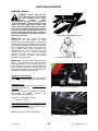
REEL FORE-AFT CONTROLS (H) & (J)
(Optional) – For headers with hydraulic reel foreaft option. Press button at (H) to move reel
forward. Press button at (J) to move reel rearward.
HEADER TILT CONTROLS (K) & (L)
(Optional) – Press button at (K) to tilt header back
for a flatter guard angle. Press button at (L) to tilt
header forward for a steeper guard angle.
Form # 46584
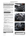
24
Issue 11/06 Web Rev_01
OPERATOR'S STATION
Header Controls (continued)
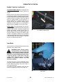
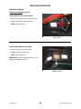
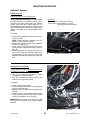
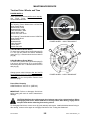
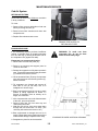
CUT HEIGHT INDICATOR (G) - The gauge on the
lift linkage can be used to identify desired cut
heights.
G
With the center link (between tractor and header)
in a mid-range position, the numbers on the gauge
indicate approximate cut (stubble) height in inches.
Adjusting center link length will affect the starting
point; eg. gauge reading 4 may indicate a 3"
(longer center link) or 5" (shorter center link) cut
height. However, the difference between gauge
readings of 4 and 8, 8 and 12, etc. will always be
about 4 inches, regardless of center link length.
Header Angle: Cut height indicator (G) can also
be used to identify header angle when cutting with
header on the ground. The gauge indicator will
decline until header contacts ground, then as
header height switch is held in down position, the
indicator reading will increase as header angle
steepens. The gauge numbers will not correspond
to actual header angle, but can be used to identify
a desired setting. See "Header Angle" in Operation
section for adjustment procedure.
CUT HEIGHT INDICATOR
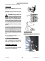
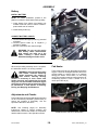
Seat Belts
The windrower is equipped with a seat belt on the
Operator’s and Trainer’s seats.
WARNING: Before starting engine,
securely fasten your seat belt and
ensure trainer’s seat belt is fastened
if occupied. The seat belt can help insure your
safety if it is used and maintained. Never wear
a seat belt loosely or with slack in the belt
system. Never wear the belt in a twisted
condition or pinched between the seat
structural members.
To fasten seat belt, pull belt completely across
your body. Push the metal eye into the buckle until
it locks. Adjust the position of the belt as low on
your body as possible.
To release, push the red button in the end of the
buckle and separate the buckle and metal eye.
SEAT BELT
Form # 46584
25
Issue 11/06 Web Rev_01
OPERATOR'S STATION
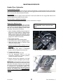
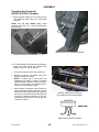
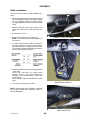
Seat Adjustments
OPERATOR WEIGHT & SEAT HEIGHT
ADJUSTMENT - Press knob (A) in to increase
suspension stiffness and seat height. Pull knob out
to decrease.
SEAT-BACK ANGLE - Pull up on lever (B),
position seat back as desired, and release lever.
A
LUMBAR SUPPORT - Rotate knob (C) to position
lumbar support as desired.
SEAT FORE-AFT POSITION - To adjust, pull out
on lever (D), move seat forward or rearward to
desired position and release lever.
SEAT FORE-AFT ISOLATOR LOCKOUT - To
lock out fore-aft isolator, push down on lever (E).
C
ARM RESTS – Left arm rest has two positions,
vertical and horizontal. Raise left hand arm rest
when leaving seat for easier exit and re-entry.
Right arm rest is mounted on side console and is
adjustable vertically at nuts (F) to operator
preference.
B
D
E
AIR SUSPENSION SEAT
F
RIGHT ARM REST
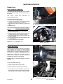
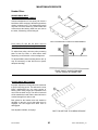
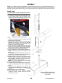
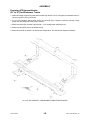
TRAINING SEAT – Retractable training seat
complete with seat belt is provided for use
as described below. To extend, raise seat
cushion and pivot front support down as
shown. For storage, collapse front support
and lower seat cushion.
WARNING: The training seat is
provided for an experienced
operator of the machine when a
new operator is being trained.
The training seat is NOT intended as a
PASSENGER SEAT or FOR USE BY
CHILDREN.
USE THE SEAT BELT whenever operating
the machine or riding as a trainer.
KEEP ALL OTHER RIDERS OFF THE
MACHINE.
TRAINING SEAT
Form # 46584
26
Issue 11/06 Web Rev_01
OPERATOR'S STATION
Operator Amenities
CUP HOLDER (A) – Provided at side console.
A
CIGARETTE LIGHTER (B)
CUP HOLDER
ASHTRAY (C)
B
C
LIGHTER & ASHTRAY
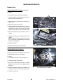
AUXILIARY POWER POINTS (D) - Two 12 volt
power outlets are provided on backside of console.
D
POWER POINTS
Form # 46584
27
Issue 11/06 Web Rev_01
OPERATION
Your Responsibilities as an Owner/Operator
CAUTION:
1. It is your responsibility to read and
understand this manual and the Header
Operator's Manual completely before
operating the windrower. Contact your
dealer if an instruction is not clear to you.
2. Follow all safety messages in the manuals
and on safety signs on the windrower.
3. Remember that YOU are the key to safety.
Good safety practices protect you and the
people around you.
4. Before allowing others to operate the
windrower, for however short a time or
distance, make sure they have been
instructed in its safe and proper use.
5. Review the manuals, safety signs and all
safety related items with all operators
annually.
6. Be alert for other operators not using
recommended procedures or not following
safety precautions. Correct these mistakes
immediately, before an accident occurs.
7. Maintain the windrower correctly. Be sure
all controls are functioning properly before
use.
8. Do not modify windrower or remove
shields. Unauthorized modifications may
impair the function and/or safety and affect
machine life.
9. Install a fire extinguisher and keep it
properly charged.
10. The safety information given in this manual
does not replace safety codes, insurance
needs or laws governing your area. Be
sure your windrower meets the standards
set by these regulations.
To the New Operator
It's natural for an operator to be anxious to get started with a new machine. Please take the time to familiarize
yourself with the windrower by reading the Operator's Manuals and safety signs before attempting operation.
Study the Starting, Driving and Stopping procedures so you will know what to expect.
Form # 46584
28
Issue 11/06 Web Rev_01
OPERATION
Break-in Period
The windrower is ready for normal operation. However there are several items to check and watch out for
during the first 100 hours, as follows:
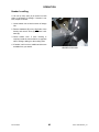
ENGINE BREAK-IN:
1. Operate engine at moderate load, avoid extremely heavy or light loading for longer than 5 minutes.
2. Avoid unnecessary idling. If engine will be idling for longer than 5 minutes after reaching operating
temperature, turn key OFF to stop engine.
3. Check engine oil level frequently. Watch for any signs of leakage. If oil must be added, use oil specified
under "Fuels, Fluids and Lubricants" in Maintenance/Service section.
NOTE: During the break-in period, a higher than usual oil consumption should be considered normal.
If windrower must be driven in cold weather (below freezing), let engine idle for 3 minutes, then operate at
moderate speed until oil has warmed up.
4. Watch coolant gauge in cab for temperature rising beyond normal operating range. Check that coolant
level at reserve tank (mounted next to radiator) stays between HOT and COLD marks on tank. If overheating problems occur, check for coolant leaks. See "Cooling System" in Maintenance/Service section.
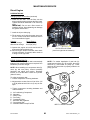
5. Change engine oil and filter after the first 25 hours and every (200 hours – 2004 & older units), (500 hours
– 2005 units) or at least once per season thereafter. See "Engine" in Maintenance/Service section.
WINDROWER BREAK-IN:
1. Until you become familiar with the sound and feel of your new windrower, be extra alert and attentive.
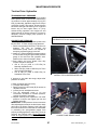
2. Check A/C compressor belt after 5 hours operation for initial stretch. Tighten as necessary. (See
Maintenance/Service section). Continue to check the belt periodically for the first 50 hours.
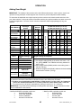
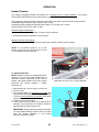
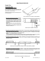
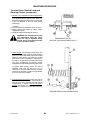
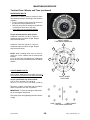
3. Check drive wheel bolt torque according to the following schedule:
• Every 15 minutes on the road or 60 minutes in the field until torque stabilizes, then
• Daily (10 hours) until no change is recorded for 3 consecutive days (30 hours), then
• Every 200 hours or annually thereafter.
Torque specification for drive wheels:
9 Bolt Rim: 130 ft.lbs. (175 N⋅m).
8 Bolt Rim: 180 ft.lbs. (245 N.m).
Torque in numbered sequence shown and repeat sequence three
times.
Check caster wheel bolt torque after the first 5 hours and every 200 hours or annually thereafter.
Torque specification for caster wheels: 9.5L-14: 50 to 60 ft.lbs. (70 to 80 N⋅m)
16.5L-16.1, 11-16 or 7.5-16: 100 ft. lbs. (135 N⋅m)
NOTE: To avoid damage to wheel disks, do not over-tighten wheel nuts.
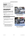
4. Replace both hydraulic oil filters after the first 10 hours and every 300 hours thereafter. See "Hydraulic
System" in Maintenance/Service section.
5. Adjust park brake after the first 10 hours and every 100 hours thereafter. See Park Brake in
Maintenance/Service section.
6. Change power wheel oil after the first 50 hours and every 1000 hours (or 3 years) thereafter. See
Maintenance/Service section.
7. Change bevel gearbox oil after the first 50 hours and every 200 hours (or annually) thereafter. See
Maintenance/Service section.
Continued next page…
Form # 46584
29
Issue 11/06 Web Rev_01
OPERATION
Break-in Period
WINDROWER BREAK-IN (Continued):
8. Re-torque four walking beam pivot bolts (B)
after the first 50 hours. Tighten to 265 ft. lbs.
(360 N·m.)
NOTE: For units with optional “behind-frame”
weight package as shown, tighten hardware to
350 ft. lbs. (470 N·m.)
B
Pre-Starting Checks: Annual
Do the following at the start of each operating
season:
CAUTION:
RE-TORQUE WALKING BEAM BOLTS
AFTER 50 HOURS
1. Review the Operator's Manual to refresh
your memory on safety and operating
recommendations.
2. Review all safety signs and other decals on
the windrower and note hazard areas.
3. Be sure all shields and guards are properly
installed and secured. Never alter or
remove safety equipment.
4. Re-acquaint yourself with the controls
before beginning operation.
5. Store a properly stocked first aid kit and
charged fire extinguisher on the
windrower.
Also:
6. Drain off excess hydraulic oil added for storage. See "Hydraulic System" in Maintenance/
Service section.
7. Remove plastic bags and/or tape from all
sealed openings (air cleaner intake, exhaust
pipe, fuel tank).
8. Charge battery and install. Be sure terminals
are clean and cables are connected securely.
9. Adjust tension on A/C compressor belt. See
Maintenance/Service section.
10. Cycle blower switch to distribute A/C
refrigerant oil. See Maintenance/Service
section.
11. Perform all Annual maintenance. See Maintenance/Service section.
Form # 46584
30
Issue 11/06 Web Rev_01
OPERATION
Pre-Starting Checks: Daily
Do the following each day before starting the engine:
CAUTION:
1. Clear the area of other persons, pets, etc.
Keep children away form machinery. Walk
around the windrower to be sure no one is
under, on or close to it.
2. Remove foreign objects from
windrower and surrounding area.
the
3. Wear close-fitting clothing and protective
shoes with slip resistant soles.
PROTECT YOURSELF
As well, carry with you any protective
clothing and personal safety devices that
COULD be necessary through the day.
Don't take chances.
You may need:
- a hard hat
- protective glasses or goggles
- heavy gloves
- respirator or filter mask
- wet weather gear
4. Protect against noise. Wear a suitable
hearing protective device such as ear
muffs or ear plugs to protect against
objectionable or uncomfortable loud
noises.
PROTECT AGAINST NOISE
5. Check the machine for leaks or any parts
that are loose, missing, broken, or not
working correctly. Use proper procedure
when searching for pressurized fluid leaks.
See "Fuel System" and "Hydraulic System"
in Maintenance/Service section.
6. Clean the windows and mirrors to be sure
of good visibility in all directions. To wash
front window, stand on side platforms and
use grab handle on cab side posts or on
front of roof. Some headers are equipped
with a traction surface across the back
tube. If not, DO NOT stand on back tube of
header.
7. Clean all lights and reflective surfaces to
be sure you are visible to others.
8. Perform all Daily Maintenance. See Maintenance/Service section.
Form # 46584
WASHING FRONT WINDOW
31
Issue 11/06 Web Rev_01
OPERATION
Start-Up Procedure
DANGER: Avoid possible injury or
death from a runaway machine.
Do not start engine by shorting across starter
terminals. Machine will start in gear and move
if normal starting circuitry is bypassed.
This machine has two safety devices which
prevent the engine from starting unless the
variable speed lever is in neutral, the steering
wheel is locked in the neutral position, and
the header drive switch is in the OFF
position. Under no circumstances are these
circuits to be deliberately rewired so that the
engine can be started with controls out of
neutral.
NEVER SHORT ACROSS STARTER TERMINALS
Start engine only from operator's seat with
controls in neutral. NEVER start engine while
standing on ground. Machine will start in gear
and move if normal starting circuitry is
bypassed.
A
Before starting engine, be sure there is plenty
of ventilation to avoid asphyxiation.
IMPORTANT: Do not tow machine to start engine.
Damage to hydrostatic drives will result.
ADJUSTING CONTROLS
ENGAGE PARK BRAKE
1. Fasten seat belt.
2. Engage park brake (A).
D
3. Move header drive switch (B) to off position.
4. Move variable speed lever to neutral position
(C).
5. Turn steering wheel until it locks. Adjust
steering wheel tilt to desired position.
B
6. Move throttle lever (D) to start-up position Lever fully back.
CHECKING INSTRUMENTS
The machine gauges and instruments provide
important information about machine operation
and condition. Familiarize yourself with the gauges
and monitor them carefully during start-up
operation. See "Instruments and Controls".
C
ADJUST CONTROLS FOR START-UP
Form # 46584
32
Issue 11/06 Web Rev_01
OPERATION
Start-Up Procedure (continued)
STARTING ENGINE
CAUTION: Be sure the area is clear of
other persons, pets etc. before
proceeding.
Temperature above 16° C (60° F):
Turn ignition key to START position until engine
starts. Release key. If engine does not start within
5 seconds of cranking, follow cold start procedure
below.
Temperature below 16° C (60° F) (cold start):
Move throttle lever (A) fully forward after turning
ignition key to START position. When engine
starts, release key and return throttle lever (A) to
low idle.
A
IMPORTANT: Do not operate starter for longer
than 15 seconds at a time. If engine does not start,
wait at least two minutes before trying again. After
the third 15 second crank attempt, allow solenoid
to cool for 10 minutes before further cranking
attempts. If engine still does not start, refer to
Trouble Shooting section.
WARNING: If starter engages with
steering wheel unlocked, variable
speed lever out of neutral, or header
clutch engaged, DO NOT START ENGINE.
Perform Neutral Lock Adjustment. (See Maintenance/Service section.)
THROTTLE - IDLE POSITION
WARMING UP ENGINE
Allow engine to run with throttle lever (A) at or near
low idle position until temperature gauge reaches
approximately 180°F (80°C).
USING A BOOSTER BATTERY
If battery charge is low and engine fails to start, an
extra 12-volt battery can be connected in parallel
with the windrower battery. Follow directions
carefully. See "Connecting Booster Battery" in
Maintenance/Service section.
Form # 46584
ALLOW ENGINE TO REACH OPERATING
TEMPERATURE
33
Issue 11/06 Web Rev_01
OPERATION
Driving the Windrower
WARNING: · Avoid driving the
machine with header removed.
Removing header decreases the
weight on drive wheels, reducing
steering control.
· If necessary to drive machine with header
removed, use transmission "field speed"
range, do not exceed half maximum engine
speed and avoid loose gravel and slopes.
· Never use windrower as a towing vehicle
when header is removed. There is
insufficient weight on the drive wheels to
provide steering control.
· Because
of
windrower
shape
characteristics, a roll-over protected (ROPS)
cab is not required. If operating with header
removed, be aware that the cab structure
will not withstand a roll-over.
AVOID DRIVING WITH HEADER REMOVED
CAUTION: HYDROSTATIC STEERING
The
machine
is
steered
hydrostatically, that is, turning the
steering wheel varies the hydraulic
flow to one drive wheel relative to the other
drive wheel. The reaction of this type of
steering is different than conventional steering
mechanisms.
Remember:
· With the engine running and the variable
speed lever in neutral, the machine will
move if the steering wheel is turned.
· Hydrostatic steering is more sensitive than
mechanical steering.
· Steering is opposite to normal when driving
in reverse.
CAUTION: 1. Never move variable
speed lever or steering wheel until
you are sure all bystanders have
cleared the area.
2. Be sure area is clear before making turns,
ends of header travel in a large arc.
3. Check the operation of all controls in a safe,
clear area before starting work. Be sure you
know
the
capacity
and
operating
characteristics of this machine.
4. Do not allow riders in or on the machine.
5. Operate only while seated in the operator's
position.
6. Never attempt to get on or off a moving
windrower.
7. Avoid sudden starts and stops.
8. Avoid inclines, ditches and fences.
9. Reduce speed when turning, crossing
slopes, or travelling over rough ground.
10. Do not allow anyone to stand behind the
machine while operating. Foreign objects
may be forcibly ejected.
CLEAR THE AREA BEFORE OPERATING
DO NOT ALLOW RIDERS
Form # 46584
34
Issue 11/06 Web Rev_01
OPERATION
Driving the Windrower (continued)
TO DRIVE FORWARD:
1. After starting engine, release park brake.
2. Dual Speed Units: For field operation, set
speed-range switch (A) to position L. For road
speeds, set control to position H.
A
3. Slowly push throttle lever (C) to full forward
(operating speed).
IMPORTANT:
• Return throttle lever (C) to low idle position
before engaging header drives.
• For field operation, always operate windrower
with speed-range control in field position and
throttle lever fully forward (maximum engine
RPM). Use controls to vary ground speed, reel
speed and conveyor speed. All systems are
designed for efficient operation at maximum
engine RPM.
SPEED-RANGE CONTROL
CAUTION: Check again to be sure all
bystanders have cleared the area.
4. Slowly move variable ground speed lever (D)
forward to desired speed.
CAUTION: Operate both steering
wheel and variable speed lever
slowly for familiarization. Remember
that steering is more sensitive when
speed-range control is in Road Speed Position.
Avoid the common tendency of new operators
to over-steer.
C
5. In situations where more tractive (lugging)
power is required, for example, driving up a
ramp, up a hill, or up out of a ditch:
Be sure speed-range control is in field position
and move the variable speed lever towards
neutral. The effect of this is similar to downshifting a standard transmission, increasing
torque at the drive wheels.
D
CONTROL LEVERS - DRIVING FORWARD
Form # 46584
35
Issue 11/06 Web Rev_01
OPERATION
Driving the Windrower (continued)
TO DRIVE REARWARD:
WARNING: Back up slowly. Steering
is opposite to normal when
reversing. Hold steering wheel at the
bottom and turn wheel in direction you want
the rear of the machine to travel.
1. Move speed-range switch (A) to field position L
(dual speed units).
2. Move throttle lever to a mid-range position (B).
NOTE: Reversing in low speed-range and at
reduced engine speed is recommended since
steering will be less sensitive than at higher speed
settings.
CAUTION: Check again to be sure all
bystanders have cleared the area.
3. Move variable ground speed lever (C) rearward
to desired speed.
STEERING OPPOSITE TO NORMAL
WHEN REVERSING
B
C
A
CONTROL LEVERS - DRIVING REARWARD
Form # 46584
36
Issue 11/06 Web Rev_01
OPERATION
Driving the Windrower (continued)
MAKING A SPIN TURN:
Hydrostatic steering gives the operator significantly
more maneuverability than mechanical steering.
CAUTION: Be sure area is clear
before making turns. Although
tractor pivots "on the spot", ends of
header travel in a large arc.
To make a spin turn:
A
1. Move the variable speed lever (A) out of its
neutral detent (towards the seat, not forward or
rearward).
2. Slowly turn the steering wheel in the desired
direction of turn. The windrower will pivot
between the drive wheels.
3. To stop the turn, slowly turn the steering wheel
back to its centered position.
CONTROL LEVERS - SPIN TURN
4. To increase the turn radius, slowly move the
ground speed lever away from neutral.
Remember that this will increase ground speed
as well.
5. To stop the turn, return all controls to neutral.
Form # 46584
37
Issue 11/06 Web Rev_01
OPERATION
Stopping Procedure
TO STOP WINDROWER:
WARNING: Do not move variable
speed lever rapidly back to neutral.
Operator may be thrown forward by
sudden stop. Always wear seat belt
when operating windrower.
B
C
1. To slow down and stop the windrower,
SLOWLY return the variable speed lever (A) to
neutral.
WARNING: Do not use park brake to
slow windrower down. This will
result in erratic machine reaction
which could cause personal injury as
well as damage to the brake mechanism.
A
2. Turn steering wheel until it locks.
3. Move throttle lever (B) to low idle position.
CONTROL LEVERS - STOPPING
NOTE: Avoid unnecessary idling. Stop engine if it
will be idling for longer than 5 minutes.
4. Move header drive switch (C) to off position to
stop header drives.
5. Engage park brake (D) if machine is to remain
stopped.
CAUTION: Park machine on flat level
ground only. Keep park brake
properly adjusted at all times. See
Maintenance/Service section.
D
ENGAGE PARK BRAKE
TO STOP ENGINE:
CAUTION: Be sure windrower is
safely parked on a flat, level surface,
header on the ground and the park
brake engaged.
IMPORTANT: Before stopping engine, run at low
idle for approximately five minutes to cool hot
engine parts (and allow turbocharger, if applicable,
to slow down while engine oil pressure is
available).
1. Turn key counter-clockwise to OFF position.
Form # 46584
38
Issue 11/06 Web Rev_01
OPERATION
Leaving the Windrower
CAUTION: Before leaving
operator's seat for any reason:
the
1. Park on level ground if possible.
2. Be sure variable speed lever is in the neutral
detent and steering wheel is locked in the
straight-ahead position.
3. Engage the park brake.
4. Fully lower header and reel.
5. Disengage header drives.
6. Stop engine and remove key from ignition. A
child or even a pet could engage an idling
machine.
7. Turn off all lights (and wiper).
8. Release seat belt.
9. Raise armrest and steering wheel for easier
exit and re-entry.
B
10. Lock the cab door when leaving the
windrower unattended. (When the door is
locked, it can still be opened from inside the
cab.)
11. To provide more secure hand and foot
mobility, preventing slipping and possible
injury, always face the windrower and use
the hand rail when dismounting (or
mounting).
A
EMERGENCY EXIT
In case exit through cab door is not possible, the
right hand side window may be opened to provide
an emergency exit. Open window, then remove
latch pivot pins (A) and push outward on window.
FOR NORMAL WINDOW OPERATION, open
latches (B) and move window to open position.
R/H SIDE WINDOW - EMERGENCY EXIT
Form # 46584
39
Issue 11/06 Web Rev_01
OPERATION
Attaching the Header
NOTE: For Harvest Headers with gauge
wheels, instructions under "Attaching" and
"Detaching the Header" which refer to the
"header stand" do not apply. Use the "stand"
position of the gauge wheels to support rear of
header. All gauge wheel positions are identified
on a decal located at each gauge wheel. Be
sure to reposition gauge wheel to field position
before operating.
1. Choose an area that is as level as possible and
set header stand (A) in the down position.
942 Header, set 2 inch (50 mm) blocks under
each end of cutterbar.
960 & 970 Series Headers, be sure header and
tractor have been properly prepared for
windrower use.
See "Preparing Tractor and Headers" in
Assembly section for details.
A
963 HEADER STAND
HEADER STAND - DOWN POSITION
CAUTION: Be sure area is clear of
bystanders, then start engine.
2. Fully retract header lift cylinders. For units with
Header Express Down option, use switch on
side console to bypass the feature.
NOTE: For 30’ & 36’ Harvest Headers with
Transport Option; when attaching to header in
transport mode, position 6 inch high (150 mm)
blocks for drive tires to provide adequate linkage
height. Blocks should be at least the width of the
drive tires and long enough that drive tires are fully
supported when attaching header.
3. Slowly drive tractor forward so that lift linkage
enters header legs. Continue to drive slowly
forward until linkage contacts support plate in
the lower header leg, and header nudges
forward. Stop engine, set parking brake and
remove key.
INSTALL CENTER LINK
4. Adjust length of center link and connect to
header at (C). For 962 and 972 headers, use
the lower, more rearward hole in mount on
header tube as shown.
NOTE: Ensure that thread length is equal at
both ends of center link. See "Header Angle for
adjustment details.
5. Check that bottom of linkage (D) is properly
engaged in header leg, contacting support plate
(E).
CHECK FOR PROPER ENGAGEMENT
Form # 46584
40
Issue 11/06 Web Rev_01
OPERATION
Attaching the Header (continued)
6. Connect driveline to header drive shaft as
follows:
• Open hinged shield at header drive shaft.
• Pull back spring loaded collar (G) on
driveline yoke and slide yoke onto header
shaft. Release collar, ensuring yoke locks
in position on shaft.
• Attach chain hook (if present) to hinged
shield at (H).
• Close hinged shield.
NOTE: For 962/963 Header only, attach chain
hook (if present) to shield (J) on connector shaft as
below.
G
H
CONNECT DRIVELINE –
912/922/933/972 HEADERS
A
J
CONNECT DRIVELINE – 962/963 HEADER
7. Hydraulic Hose Connections:
910 Series Headers: No hydraulic connections
between header and tractor. Couple (A) to (B)
and (D) to (E) for these units. Failure to do so
will cause header drive circuit to overheat,
causing potential hydraulic component failure or
product performance problems.
B
HYDRAULIC CONNECTIONS - R/H SIDE
920 & 930 Series Headers: Two connections
are made at couplers (A) and (B) at the header
right hand leg. One connection is made at
coupler (D) at the header left hand leg. For 912
& 922 Headers with Hay Conditioner equipped
with Hydraulic Roll Opener cylinders, connect
hose from these cylinders at coupler (C).
C
940, 960 & 970 Series Headers: Two
connections are made at couplers (A) and (B) at
the header right hand leg. Two connections are
made at couplers (C) and (E) at the tractor left
hand leg. One connection is made at coupler
(D) at the header left hand leg.
A - reel drive pressure
B - reel drive return
C - reel lift (or Hay Conditioner Roll Opener
cylinder circuit, if equipped)
D - conveyor drive pressure
E - conveyor drive return
D
F
HYDRAULIC & ELECTRICAL CONNECTIONS
L/H SIDE
8. Connect the header electrical wiring harness at
connector (F).
Form # 46584
E
41
Issue 11/06 Web Rev_01
OPERATION
Attaching the Header (continued)
9. Start engine. Activate header lift cylinders
(switch on ground speed lever) to raise header
fully. Stop engine and remove key.
10.
DANGER: To avoid bodily injury from
fall of raised header, always engage
header lift cylinder stops (A) when
working on or around raised header.
A
11. Attach float springs to front of linkage, both
sides. Secure with "L" pin (B) and hair pin.
NOTE: For 12’ & 15’ 972 headers, connect pin
at second hole (F) to ensure proper float.
ENGAGE LIFT CYLINDER STOPS
12. Install pin through header leg, (engaging Ubracket in lift linkage), both sides.
910, 920, 930 & 940 Series Headers: Secure Lpin (C) behind lug (D).
962 Header: Secure 8" clevis pin with lynch pin.
912, 922, 933 & 970 Series Headers: Secure 6½"
clevis pin (E) with split ring.
B
F
E
ATTACH FLOAT SPRINGS
D
C
L-PIN DESIGN
CLEVIS PIN DESIGN
INSTALL PINS THROUGH LEGS
F
13. Raise header stand to storage position (F).
14. Disengage header lift cylinder stops and lower
header to ground. Check header flotation and
adjust if required. See "Header Flotation" in
Operation section (page 49).
15. For headers with hay conditioner, attach
forming shield rear support straps to forming
shields.
Form # 46584
963 HEADER
OTHER MODELS
HEADER STAND - STORAGE POSITION
42
Issue 11/06 Web Rev_01
OPERATION
Adding Rear Weight
IMPORTANT: The stability of the machine varies with different attachments, tractor options, terrain and
operator’s driving technique. Install weight at rear of tractor to provide adequate machine stability.
To determine the additional rear weight required, pick the tractor model, header model and size to find
your “base machine”. Add up the values for the base machine plus options/conditions to obtain a score for
a particular application. Go to the "score" column to determine which weight packages (if any) are
required.
14’
16’
18’
962/963
Harvest
Header
30’
36’
52
68
72
52
90
96
101
0
0
0
0
0
0
0
0
0
0
43
25
922 Auger
Header
Header Size→
9250/9350*
Base Machine
9352**
Base Machine
Pick Up Reel
Double Sickle
Cross Auger
Hay Conditioner
Gauge Wheels/
Transport
Gauge Rollers
Formed Casters
Hilly Terrain
Score
0 - 114
115 - 124
125 - 134
135 - 164
165 -234
235 – 260
(see NOTE)
Over 260
(see NOTE)
972 Harvest Header (12’ to 36’)
973 Harvest Header (21’ to 39’)
15’
18’
21’
25’
30’ 36’/39’
108
0
17
46
77
111
195
70
114
14
33
64
97
133
224
0
0
0
0
29
0
7
0
41
0
7
0
0
0
5
30
0
0
6
30
0
14
7
30
0
15
7
30
43
17
7
0
47
19
7
0
0
0
18
0
0
0
0
0
15
0
0
43
25
0
43
25
0
43
25
0
43
25
15
43
25
15
43
25
15
43
25
15
43
25
0
43
25
0
43
25
Weights Packages
Used
No weights required
A
2 of A
2 of A plus B
2 of A plus B plus C
2 of A plus B plus C
USE CARE
DO NOT USE THIS
HEADER
CONFIGURATION
12’
No weights required
Header Model→
Weight Package Descriptions
A = One weight bundle (B2266) in the tractor rear frame = 187
lbs. (85 kg). NOTE: Two of B2266 are factory installed on
9352** units.
B = Basic weight bundle (B2980) added to the walking beam =
400 lbs. (180 kg).
C = Additional weight bundle (B2981) added to the basic walking
beam bundle = 300 lbs. (135 kg).
NOTE: For scores of 235 and higher with the 9352** tractor only, score may be reduced by having
an authorized tire dealer install calcium chloride fluid in the rear caster tires as follows:
• To reduce score by 60 points: Install 250 lbs. (115 kg) in each 11 x 16 or 16.5 x 16.1 caster tire.
(This is the maximum allowable for 11 x 16 tire.) Fluid can not be added to the 7.5 rear tire.
• To reduce score by 100 points: Install 400 lbs. (180 kg) in each 16.5 x 16.1 caster tire
IMPORTANT: To prevent structural damage to walking beam and casters, do not install fluid in caster
tires on 9250/9350* model tractors.
** MacDon 9352 equivalent models are:
•
Westward 9352
•
Prairie Star 4952
•
Premier 2952
•
Harvest Pro 8152
* MacDon 9250/9350 equivalent models are:
•
Westward 9250/9350
•
Prairie Star 4940/4950
•
Premier 2940/2950
•
Harvest Pro 8140/8150
Form # 46584
43
Issue 11/06 Web Rev_01
OPERATION
Adding Rear Weight (continued)
To install weight bundle B2266 in rear tractor
frame:
1. Install bolt (A) through welded nut in existing
tractor weight (B) and start jam nut on bolt (A).
2. Insert weights (C) forward of welded pin (D) as
shown, then move weight back towards rear of
tractor.
3. After weights are in position, tighten bolt (A)
against the new weight (C), then tighten jam nut
against weight (B).
INSTALLATION OF WEIGHTS (REAR VIEW)
NOTE: Install complete weight pack on same side
of pin (D). Total weight per pack is 187 lbs. (85
kg).
NOTE: Installation instructions for behind the
frame weight packages B2980 and B2981 are
included with the kits.
direction of travel
OPTIONAL REAR WEIGHT PACK
(SIDE VIEW)
Form # 46584
44
Issue 11/06 Web Rev_01
OPERATION
Detaching the Header
1. Activate header lift cylinders (switch on ground
speed lever) to raise header fully. For units with
Header Express Down option, use switch on
side console to bypass the feature. Lower the
reel (second switch on lever). Stop engine and
remove key.
2.
A
DANGER: To avoid bodily injury from
fall of raised header, always engage
header lift cylinder stops (A) when
working on or around raised header.
ENGAGE LIFT CYLINDER STOPS
3. Remove "L" pin (B), both sides and detach float
springs.
B
DETACH FLOAT SPRINGS
C
4. Remove pin (C) from lower header leg, both
sides.
C
L-PIN DESIGN
CLEVIS PIN DESIGN
REMOVE HEADER PINS
5. Lower header stand into position (E).
942 Multi-Crop Header: Place 2 inch (50 mm)
blocks under cutterbar at both ends of header.
6. Disengage header lift cylinder stops.
7. Be sure area is clear of bystanders, then start
engine. Retract lift cylinders to fully lower
header. Stop engine and remove key from
ignition.
963 HEADER STAND
E
HEADER STAND - DOWN POSITION
Form # 46584
45
Issue 11/06 Web Rev_01
OPERATION
Detaching the Header (continued)
DANGER: Wait for all movement to
stop. A rotating driveline can cause
entanglement resulting in serious
personal injury or death.
8. Disconnect driveline from header shaft as
follows:
• Pull back spring-loaded collar on driveline
yoke and remove yoke from header shaft.
• Detach chain (if present) from header
hinged shield.
• Pull back spring-loaded collar and store
driveline on pin welded to tractor frame at
(E).
E
DETACH AND STORE DRIVELINE
9. Disconnect hydraulic hoses at quick couplers at
right and left-hand legs.
IMPORTANT: Where possible, connect hoses
to each other for storage except fore-aft as
noted below. Plug or cap all other couplers to
prevent hydraulic system contamination. Store
tractor reel drive hoses as shown at (G) to avoid
interference during hook-up.
G
WARNING:
For
headers
with
hydraulic reel fore-aft, never connect
the header fore-aft couplers to each
other. This would complete the circuit
and allow the reel to creep forward in
transport, resulting in instability.
10. Disconnect electrical wiring harness.
NOTE: If a Hay Conditioner is installed, detach
supports between tractor frame and conditioner
forming shield.
11. Adjust length of center link to release load on
pins. Disconnect center link at header by
removing pin (C).
TRACTOR REEL DRIVE HOSES - STORAGE
12. Slowly back tractor away from header. If hay
conditioner is attached, watch clearances at left
and right sides.
WARNING: Avoid driving the tractor
with header removed. Removing
header decreases the weight on
drive wheels, reducing steering
control. If necessary to drive tractor with
header removed, use transmission low speed
range, do not exceed half-maximum engine
speed and avoid loose gravel and slopes.
DETACH CENTER LINK AT HEADER
WARNING: Harvest Header with
Transport Option This windrower
tractor is not intended as a towing
vehicle for the Harvest Header
Transport configuration. If necessary to use
the tractor in this manner, add a minimum 2000
lb. (910 kg) counterweight on the lift linkage.
Form # 46584
46
Issue 11/06 Web Rev_01
OPERATION
Operating the Header
Correct operation reduces crop loss and allows
cutting of more acres. The length of service you
receive from your windrower depends upon
thorough lubrication, and proper maintenance and
adjustments.
CAUTION: Do not mount anything on
the windrower tractor except the
headers and attachments designed
for use with it. Unapproved
attachments may change the stability and
controllability of the machine.
A
Header Lift Cylinder Stops
DANGER: To avoid bodily injury or
death from fall of raised header,
always engage cylinder stops before
going under header for any reason.
HEADER HEIGHT SWITCH
Cylinder stops are located on both header lift
cylinders on windrower.
To engage cylinder stops:
1. Press top of header height switch (A) to raise
header to maximum height.
B
2. Lift retainer (B) up to release cylinder stop (C).
Lower stop onto cylinder.
3. To store, push up on stop (C) until retainer
locks in storage position.
C
LIFT CYLINDER STOP - ENGAGED
LIFT CYLINDER STOP - STORAGE
Form # 46584
47
Issue 11/06 Web Rev_01
OPERATION
Header Angle
Header angle is adjustable by changing the length
of the center link between header and tractor.
HEADER TILT HYDRAULIC
ADJUSTMENT
Header angle adjustment ranges:
910, 920, 930 Series Headers: 8° to 16°
940 Series Headers: 6° to 13°
960 Series Headers: 13° to 21°
970 Series Headers: 9.5° to 21°
An optional kit is available which allows adjustment
of header angle from the cab by means of a
hydraulic cylinder.
See “Options and Attachments” section for order
numbers. See “Header Controls” in Operator’s
Station section for identification of hydraulic
header angle controls.
IMPORTANT: For units with hydraulic header tilt
option, be aware that when cutting on the ground
and using the hydraulic center link to adjust header
angle on the go, the flotation will be affected. To
prevent excessive guard breakage when
conditions are not suited to heavier float (e.g.
rocky or wet), do not use the tilt control on the go.
Instead, use the header height switch as described
below.
NOTE: Above figures are guard angle in degrees
below horizontal.
IMPORTANT: A flatter header angle is recommended for normal conditions. A flatter angle
reduces sickle section breakage and reduces soil
build-up at the cutterbar in wet conditions.
Use a steeper angle to cut very close to the
ground, or for better lifting action of down crops.
IMPORTANT: Changing header angle will affect
flotation. Steepening the header angle makes
header heavier while flattening the header angle
makes header lighter. Always check flotation after
adjusting header angle.
To adjust header angle with mechanical link:
1. Unlock collar (C) by tapping it in a counterclockwise direction.
2. Using a long punch in hole (D), turn the center
link until the desired header angle is reached.
Shortening the link will give a flatter header
angle, while lengthening the link provides
steeper angles.
3. Lock collar (C) against link body by tapping in a
clockwise direction to secure the position.
HEADER ANGLE MECHANICAL ADJUSTMENT
To adjust header angle when cutting on the ground (without hydraulic option):
When cutting with header on the ground, the header height switch can be used to adjust header angle "on the
go". Familiarize yourself with how the header reacts during this adjustment to take full advantage of the
feature.
1. Lower header by pressing bottom of header height switch until cutterbar just touches ground. At this point,
cutterbar is at the flattest guard angle.
2. If a steeper angle is desired, continue pressing bottom of switch. This will steepen the guard angle until lift
cylinders are fully retracted.
3. To adjust angle from steeper to flatter, press the top of the header height switch to extend cylinders a small
amount. Once the flattest angle is reached, further activating the switch will lift the cutterbar off the ground.
Use this adjustment in combination with the center link adjustment (above) to achieve the desired range
through which the header angle moves before header lifts off the ground.
See "Header Controls" in Operator's Station section for use of header height switch and cut height indicator
with regard to header angle.
Form # 46584
48
Issue 11/06 Web Rev_01
OPERATION
Header Levelling
A 1/4 inch (6 mm) shim (A) is located on both
sides of windrower lift linkage. If header is not
level, adjust as follows:
1. Lower header onto a block so back of linkage
lifts.
B
A
2. Remove hardware (B) on the high side of the
header and remove shim (A). Replace hardware (B).
3. Check header level. If more levelling is
required, install the removed shim on opposite
side of linkage, adding it to the existing shim.
4. If header is still not level, additional shims are
available from your dealer.
Form # 46584
HEADER LEVELLING
49
Issue 11/06 Web Rev_01
OPERATION
Header Flotation
The following suggested header float settings are a starting point for normal conditions. Your specific
requirements and conditions may require heavier or lighter float.
Force required to lift the cutterbar off ground at each end of the header (with lift cylinders fully retracted):
910/920/932 Auger Headers: 100 to 120 lbs. (445 - 535 N)
912/922/933 Auger Headers & 942 Multi-Crop Header: 75 to 85 lbs. (335 - 380 N)
Draper Headers: 50 to 70 lbs. (220 - 310 N)
Benefits of lighter float settings:
1. Less cutting component breakage in rough or stony conditions.
2. Avoids soil build-up at cutterbar in wet conditions.
Benefits of heavier float settings:
1. When cutting very close to the ground, enables the cutterbar to follow ground contours.
NOTE: For all headers except 12’ & 15’ 972
Header, use top hole (A) in float linkage. For 12’ &
15’ 972 Header, use lower hole (B).
A
B
To adjust header float:
NOTE: Because of end-to-end weight differential,
dimension (C) at left and right drawbolt will be
different to achieve equal float at both ends of
header. Also, lighter headers will require a larger
dimension (C), heavier headers a smaller
dimension (C).
USE HOLE “B” FOR 12’ & 15’ 972 HEADER
1. Raise header fully, shut off engine, remove key.
2. Loosen nut (D).
3. Turn spring drawbolt (E) clockwise to increase float
(which makes header lighter when lowered to ground).
Turn bolt counter-clockwise to decrease float (which
makes header heavier when lowered).
4. Tighten nut (D) to lock position.
5. Lower header fully and check float at both ends of
cutterbar. Force required to lift cutterbar should be
approximately the same at both ends.
E
D
C
IMPORTANT: Spring loaded gauge wheels (available
on some draper headers) have an effect on header
float. See “Header Floatation” in your header
operator’s manual for details.
FLOAT ADJUSTMENT
Form # 46584
50
Issue 11/06 Web Rev_01
OPERATION
Transporting the Windrower
C
WARNING: Do not drive windrower
on a road or highway at night, or in
conditions which reduce visibility,
such as fog or rain. The width of
the windrower may not be apparent under
these conditions.
WARNING: Avoid driving the
tractor with header removed.
Removing header decreases the
weight on drive wheels, reducing
steering control. If necessary to drive tractor
with header removed, use transmission low
speed range, do not exceed half maximum
engine speed and avoid loose gravel and
slopes.
A
HEADER DRIVE SWITCH OFF &
SPEED-RANGE SWITCH TO HIGH
WARNING: Harvest Header with
Transport Option:
This windrower tractor may be used to tow
21’ & 25’ harvest headers when a MacDon
approved towing package and weight box
are used.
Do not use this windrower tractor to tow 30’,
36’ or 39’ harvest headers. Instead, refer to
the 30/36/39’ header manuals for instructions
on towing these headers.
CAUTION:
1. Check local laws for width
regulations and lighting or marking
requirements before transporting
on roads.
LIGHT SWITCH TO "ROAD" POSITION
2. Move header drive switch (A) to off
position.
6. Before driving windrower on roadway,
clean all reflective surfaces and slow
moving vehicle emblem at rear of
machine. Adjust rear view mirror and
clean windows.
WARNING: To avoid possible loss
of control, set ground speed lever
to not more than half maximum
forward speed before changing
speed-range switch position.
7. Transport windrower with header fully
raised and reel fully lowered. Maintain
adequate visibility and be aware of
roadside obstructions, oncoming traffic
and bridges.
3. For road speeds, move speed-range
switch (C) to road (high) position.
Remember steering is more sensitive in
this speed range.
8. When travelling down hill, reduce speed
and keep header at a minimum height.
This provides maximum stability if
forward motion is stopped for any reason.
Raise header completely at bottom of
grade to avoid contacting ground.
4. Before driving windrower on a roadway,
be sure flashing amber lamps, red tail
lamp and head lamps are clean and work
properly. Turn light switch (B) to ROAD
position to activate these lamps. Always
use these lamps on roads to provide
warning to other vehicles.
9. Travel speed should be such that
complete control and machine stability
are maintained at all times.
5. Do not use field lamps on roads, other
drivers may be confused by them.
Form # 46584
10. Stop, look and listen before entering a
roadway. Stay on correct side of the road
and pull over if possible to let faster
traffic pass. Slow down and signal as you
turn off.
51
Issue 11/06 Web Rev_01A
OPERATION
Transporting the Windrower
TOWING THE WINDROWER ON A TRAILER
For transporting the windrower other than under its
own power, a side mount trailer (A) carrying all
four windrower wheels is recommended.
Also acceptable are side mount trailers (B) where
the windrower tail wheels remain on the ground.
For this type, tighten caster set screws, step 7,
below.
For narrower headers, front or rear mount trailers
may be used, providing local laws regarding width
regulations are adhered to.
WARNING: When towing
windrower on a trailer:
SIDE MOUNT TRAILER - TYPE (A)
the
1. Keep header fully raised and reel fully
lowered.
2. Chain windrower securely to trailer. Run
chains through triangular brackets (C) at
rear of tractor frame legs and through
anchor (D) at rear of frame. Be sure
windrower weight is centered on trailer for
stable load. Block drive wheels to prevent
movement.
SIDE MOUNT TRAILER - TYPE (B)
3. Transport width is approximately 20 ft. (6.1
m). Check local laws for width regulations
and lighting or marking requirements.
C
4. Remember that when towing windrower
sideways or backwards, slow moving
vehicle emblem, reflectors and warning
lights are not easily visible. It is your
responsibility to adequately mark the load
when transporting in this fashion.
D
5. Set light switch to FLASHER position to
activate amber lamps.
CHAIN WINDROWER TO TRAILER
6. Do not tow the windrower on a roadway at
night, or in conditions which reduce
visibility, such as fog or rain. The width of
the load makes it unsafe to transport under
these conditions.
7. If towing at speeds over 16 mph (26 km/h),
on a type (B) trailer:
a. Align caster wheels with trailer wheels.
b. Tighten caster setscrews (E) to 20 ft. lbs.
(27 N.m) to prevent erratic movement of the
casters. Failure to do this will result in
caster damage and could cause loss of
control.
c. Loosen setscrews after transport.
E
E
MODEL XX50/XX40
MODEL XX52
CASTER SETSCREWS
Form # 46584
52
Issue 11/06 Web Rev_01
OPERATION
Transporting the Windrower
TOWING THE WINDROWER ON A TRAILER (continued)
WARNING: When towing the
windrower on a trailer (continued):
8. For model 9352/4952/2952/8152 Tractors,
when towing on a front or rear mount
trailer, lock casters in a straight-ahead or
straight-back position with L-pin (F). Secure
L-pin with hairpin in lock or storage
position. (See storage position, lower right
photo on page 52.)
F
9. Do not tow at speeds over 25 mph (40
km/h). Travel speed should be such that
complete control and stability are
maintained at all times.
10. Be aware of roadside obstructions,
oncoming traffic and bridges. Take care
when travelling over rough terrain or on
slopes.
CASTER TRANSPORT LOCK –
MODEL XX52 TRACTORS
11. Be sure the total weight of the trailed
vehicle NEVER EXCEEDS the weight of the
towing vehicle, unless the trailed vehicle is
equipped with remote brakes.
NOTE: Windrower weighs 8000 to 10000 lbs.
(3600 to 4500 kg) depending on header size.
Stopping
distance
increases
with
increasing speed as the weight of the trailed
vehicle increases, especially on hills and
slopes.
12. IMPORTANT: Before towing, plug or cover
muffler exhaust to prevent the turbine from
turning without lubrication. This "free-wheeling"
of the turbocharger can cause damage.
Form # 46584
53
Issue 11/06 Web Rev_01
OPERATION
Transporting the Windrower
TOWING WINDROWER WITHOUT TRAILER
The best method for transporting a disabled
windrower is to haul it on a suitable trailer or
flatbed. (See Towing Windrower on a Trailer.)
In emergency situations, for example, towing out of
a field or into a shop, windrower may be towed
without a trailer, providing the following
precautions are followed:
1. Attach windrower to towing vehicle.
WARNING:
A
proper
towing
apparatus is critical to safe towing.
Use the following guidelines:
DO NOT ATTACH TO WALKING BEAM
• Do not attach directly from hitch to walking
beam (B). Slope of tow bar will not provide
proper transfer of braking force to
windrower, causing loss of control.
• For proper steering, towing apparatus
should be attached to both left and right
hand frame members (C) and should attach
to tow bar at same height (D) as towing
vehicle hitch.
• Towing apparatus should be removed for field
operation, to avoid interference with windrow.
ATTACH TOWING APPARATUS TO FRAME
CAUTION:
With
final
drives
disengaged, the windrower may roll
on a sloped surface. Before
disengaging final drives, attach
windrower to towing vehicle. After towing,
engage drives and park brake before detaching
from towing vehicle.
2. Disengage final drives:
- Remove cover (A) at center of drive wheels.
- Replace with dished side facing in.
TOW BAR PARALLEL TO GROUND
IMPORTANT: Failure to disengage final
drives before towing will result in serious
transmission damage.
Do not exceed 16 mph (26 km/h) when towing
windrower. Do not use this towing method for
normal transporting of windrower. Even with
final drives disengaged, rolling speeds of more
than 16 mph (26 km/h) will cause final drive
gears to run at excessive speeds, possibly
destroying the unit.
After towing, reverse cover (A) to re-engage
final drives. Be sure plunger at center of wheel
pops out to engage drive.
A
DISENGAGE FINAL DRIVES
Form # 46584
54
Issue 11/06 Web Rev_01
OPERATION
Transporting the Windrower
TOWING WINDROWER WITHOUT TRAILER
(continued)
WARNING: When towing
windrower without a trailer:
the
F
3. For model 9352/4952/2952/8152 Tractors,
lock casters in a straight-ahead or straightback position with L-pin (F). Secure L-pin
with hairpin in lock or storage position. (See
storage position, lower right photo on page
52.)
4. Be sure the towing vehicle is heavier than
the windrower.
NOTE: Windrower weighs 8000 to 10000 lbs.
(3600 to 4500 kg) depending on header size.
Remember stopping distance increases
when towing, especially on hills and slopes.
CASTER TRANSPORT LOCK –
MODEL XX52 TRACTORS
5. Do not exceed 16 mph (26 km/h) when
towing windrower.
6. Remember that when towing windrower
backwards, slow moving vehicle emblem,
reflectors and warning lights are not easily
visible. It is your responsibility to
adequately mark the load when transporting
in this fashion.
7. Set light switch to FLASHER position to
activate amber lamps.
8. Do not tow the windrower on a roadway at
night, or in conditions which reduce
visibility, such as fog or rain. The width of
the load makes it unsafe to transport under
these conditions.
9. Be aware of roadside obstructions,
oncoming traffic and bridges. Take care
when travelling over rough terrain or on
slopes.
10. IMPORTANT: Before towing, plug or cover
muffler exhaust to prevent the turbine from
turning without lubrication. This "free-wheeling"
of the turbocharger can cause damage.
Form # 46584
55
Issue 11/06 Web Rev_01
OPERATION
Storage Procedure
Do the following at the end of each operating
season:
CAUTION:
1. Clean the windrower thoroughly. Never use
gasoline, naphtha or any volatile material
for cleaning purposes. These materials may
be toxic and/or flammable.
2. Store windrower in a dry protected place.
Never operate engine in a closed building.
Proper ventilation is required to avoid
exhaust gas hazards.
3. Remove the battery. Bring to full charge and
store in a cool, dry place not subject to
freezing. Remember when working around
storage batteries that all of the exposed
metal parts are "live". Never lay a metal
object across the terminals because a spark
and short circuit will result.
4. Cover cutterbar and knife guards to prevent
injury from accidental contact.
Also:
5. If stored outside, always cover windrower with a waterproof tarpaulin or other protective material. This will
protect the switches, instruments, tires, etc. from inclement weather.
If no cover is available; seal air cleaner intake and exhaust pipe with plastic bags and/or waterproof tape.
6. If possible, block up windrower to take weight off tires. If it is not possible to block up the machine, increase
tire pressure by 25% for storage. Adjust to recommended pressure before next use.
7. Repaint all worn or chipped painted surfaces to prevent rust.
8. Lubricate the windrower thoroughly, leaving excess grease on fittings to keep moisture out of bearings.
Apply grease to exposed threads and sliding surfaces of components.
9. Check for worn components and repair. Tighten loose hardware and replace any missing hardware. See
Specifications section for torque charts.
10. Check for broken components and order replacements from your dealer. Attention to these items right
away will save time and effort at beginning of next season.
11. Add rust inhibitor to the engine oil.
Diesel Engine - use 10 oz (300 ml)
Run engine to operating temperature to mix inhibitor with oil.
12. To prevent condensation, fill hydraulic oil reservoir to filler neck with approved hydraulic system oil. See
"Fuels, Fluids and Lubricants" in Maintenance/Service section.
13. Test engine coolant anti-freeze concentration to ensure it is sufficient to protect engine against lowest
expected temperature.
Form # 46584
56
Issue 11/06 Web Rev_01
MAINTENANCE/SERVICE
Service Procedures
CAUTION: To avoid personal injury,
before servicing machine or opening
drive covers:
1. Fully lower header and reel.
2. Disengage header drive clutch.
3. Stop engine and remove key.
4. Engage park brake.
STAY CLEAR OF DRIVELINE
AND ALL MOVING PARTS
5. Wait for all moving parts to stop.
Wear close-fitting clothing and cover long hair.
Never wear dangling items such as scarves or
bracelets.
Wear protective shoes with slip-resistant soles,
a hard hat, protective glasses or goggles and
heavy gloves.
Be prepared if an accident should occur. Know
where the first aid kit and fire extinguisher are
located and how to use them.
Keep the service area clean and dry. Wet or
oily floors are slippery. Wet spots can be
dangerous when working with electrical
equipment. Be sure all electrical outlets and
tools are properly grounded.
Use adequate light for the job at hand.
Park on level surface when possible. Block
wheels securely.
Replace all shields removed or opened for
service.
Use only service and repair parts made or
approved by the equipment manufacturer.
Substituted parts may not meet strength,
design or safety requirements.
Keep the windrower clean. Do not allow oil or
grease to accumulate on the service platform,
ladder or controls.
Never use gasoline, naphtha or any volatile
material for cleaning purposes. These
materials may be toxic and/or flammable.
Form # 46584
57
Issue 11/06 Web Rev_01
MAINTENANCE/SERVICE
Seat Belt
Inspection and Maintenance
R/H Step Ladder – Use & Storage
Keep the operator and trainer seat belts in
good condition as follows:
A storable ladder is provided on the right hand side
of the tractor for access to the maintenance
platform.
1. Keep sharp edges and items that can
cause damage away from the belts.
For storage, swing ladder up and pivot arm (A)
down as shown.
2. From time to time, check belts, buckles,
retractors, tethers, slack take-up system
and mounting bolts for damage.
3. Replace all parts that have damage or
wear.
A
4. Replace belts that have cuts that can
weaken the belt.
5. Check that bolts are tight on the seat
bracket or mounting.
6. Keep seat belts clean and dry. Clean only
with a soap solution and warm water. DO
NOT use bleach or dye on the belts, as this
may weaken the material.
Operator Presence System
Make sure the Operator Presence System is
operating as follows:
1. With the windrower engine running, place
the park brake on and the ground speed
lever in neutral.
2. With everyone clear of the machine,
engage header drive switch.
3. After header drives are running, stand up
out of the seat. In approximately 5 seconds
the header should shut off. If not, the
Operator presence system requires
adjustment. See your dealer.
NOTE: To restart the header, the operator must
move the header engage switch to “OFF” position
and back to the “ON” position again.
Form # 46584
58
Issue 11/06 Web Rev_01
MAINTENANCE/SERVICE
Fuels, Fluids and Lubricants
DIESEL FUEL
Use Grade No. 2 - D fuel, as defined by ASTM Designation: D 975 for diesel fuels.
NOTE: When temperature is very cold, the use of a mixture of No. 1 and No. 2 Diesel Fuel is permitted for a
short period of time, providing the following specifications are met:
Sulphur Content - less than 1% by weight, preferably less than .5%.
Water and Sediment - for maximum filter life, should not exceed .1% by weight.
Cetane Number - 40 minimum. In cold weather or high-altitude operation, a higher cetane number (45 to 55) is
desirable.
Diesel Fuel Conditioner is available from your dealer. The use of diesel fuel conditioner will:
1.
2.
3.
4.
Clean fuel injectors, valves and manifolds for increased service life.
Disperse insoluble gummy deposits that can form in the fuel system.
Separate moisture from the fuel.
Stabilize fuel in storage.
ENGINE COOLANT
Use a 50/50 mix of water and anti-freeze for protection to -30° F (-34° C).
Anti-freeze Specification: Ethylene-glycol or propylene-glycol fully formulated, containing a pre-charge
supplemental coolant additive (SCA) and meeting ASTM Designation: D 4985.
GREASE
Use an SAE Multi-Purpose High Temperature Grease with Extreme Pressure (EP2) Performance and
containing a maximum of 1% moly (molybdenum disulphide).
For driveline slip-joints only, increased moly content (up to 10%) is recommended. IMPORTANT: Do not
use this higher moly content grease on bearings, as it may cause excessive wear in high speed applications.
HYDRAULIC OIL
For Australian Units Only – Use SAE 15W40 complying with SAE specs for API Class SJ and CH-4 engine
oil.
For All other Units – Use single grade trans-hydraulic oil.
The following oil company and equipment
The following oil company and equipment
manufacturer brand names are recommended:
manufacturer brand names are acceptable:
Petro Canada Duratran
New Holland Hydraul
Case IH Hy-Tran Plus®
Esso/Exxon Hydraul 56
John Deere Quatrol® J20C
Shell Donax TD
Agco Power Fluid 821XL
Form # 46584
59
Issue 11/06 Web Rev_01
MAINTENANCE/SERVICE
Fuels, Fluids and Lubricants (continued)
ENGINE OIL
SAE 15W40 complying with SAE specs for API Class SJ and CH-4 engine oil minimum. High grade oil would
be API CI-4SK or API CI-4.
POWER WHEEL GEAR LUBRICANT & BEVEL GEAR BOX LUBRICANT
Petro Canada: Traxon E Synthetic 75W-90
Esso/Exxon: SPARTAN Synthetic 220 EP
Shell: OMALA HD 220
Mobil: Mobilube SHC 75W-90
Texaco: Pinnacle 220 EP Synthetic Gear Lubricant
Chevron: Tegra Synthetic Gear Lubricant ISO 220
Use ISO VG220 synthetic gear lubricant. The
following oil company brand names are
recommended:
STORING LUBRICANTS
IMPORTANT: Your machine can operate at top efficiency only if clean lubricants are used. Use clean
containers to handle all lubricants. Store them in an area protected from dust, moisture and other
contaminants.
SYSTEM CAPACITIES
S.I.
U.S.
284 L
75 gal.
65 L (approx.)
57 L
17 gal. (approx.)
15.2 gal.
1.6 L
1.7 qt.
1350 mL
1800 mL
45 oz.
60 oz.
18 L
4.8 gal.
Diesel Engine Crankcase: Less Filter
With Filter
9.5 L
10.4 L
10 qts.
11 qts.
Air Conditioning System:
Refrigerant (R134a)
Oil (SP-16 PAG)
1.36 kg
240 cc*
3 lbs.
8.1 fl.oz.*
Fuel Tank
Hydraulic System: Total (varies with options)
Reservoir Capacity
Bevel Gear Box
Power Wheels:
9 Hole Rim Mount
8 Hole Rim Mount (Model XX52 Tractors)
Engine Cooling System: Diesel
* - This amount of oil is the full system requirement and is included in a new compressor.
Form # 46584
60
Issue 11/06 Web Rev_01
MAINTENANCE/SERVICE
Greasing the Windrower Tractor
See "Fuels, Fluids and Lubricants" for recommended greases.
The following greasing points are marked on the
windrower by decals showing a grease gun (A),
and grease interval (B) in hours of operation. Use
the engine hour meter in the cab and the
"Maintenance Checklist" provided to keep a record
of scheduled maintenance.
SAMPLE GREASE DECAL
Procedure:
1. Wipe grease fitting with a clean cloth before
greasing, to avoid injecting dirt and grit.
2. Inject grease through fitting with grease gun
until grease overflows. Inject grease slowly to
prevent seal damage.
3. Leave excess grease on fitting to keep out dirt.
4. Replace any loose or broken fittings
immediately.
5. If fitting will not take grease, remove and clean
thoroughly. Also clean lubricant passageway.
Replace fitting if necessary.
6. Store grease gun on tractor frame at (C).
C
DANGER: Stay clear of drivelines
until all movement has stopped.
Entanglement with rotating driveline
will cause serious personal injury or death.
Avoid loose fitting or dangling clothing.
GREASE GUN STORAGE
10 Hours
STAY CLEAR OF ROTATING DRIVELINES
E
TRANSMISSION DRIVELINE SLIP JOINT (E) ONE FITTING
D
50 Hours
NOTE: For Harvest Header, there are two more 10
Hour fittings on driveline connector shaft.
DRIVELINE (D) - FIVE FITTINGS
(2 CROSSES, 1 SHAFT, 2 SHIELD)
Form # 46584
61
Issue 11/06 Web Rev_01
MAINTENANCE/SERVICE
Greasing the Windrower Tractor:
50 Hours (continued)
J
A
CASTER PIVOTS: (J) – FOUR FITTINGS
MODEL XX52 TRACTORS
CASTER PIVOTS: (A) - TWO FITTINGS
MODEL XX50/XX40 TRACTORS
E
B
WALKING BEAM PIVOT (E) - ONE FITTING
HEADER DRIVE PULLEY (B) - ONE FITTING
F
C
TOP LIFT LINK REAR PIVOT (F) - TWO FITTINGS
HEADER CLUTCH PIVOT (C) - ONE FITTING
G
H
D
TRANSMISSION DRIVELINE U-JOINTS (D) TWO FITTINGS
NOTE: There is a hole at (H) where a screw-driver
can be worked against flywheel ring gear to turn
driveline for zerk access, or a Cummins barring tool
may be used as described on page 64.
Form # 46584
FORKED CASTER SPINDLE BEARINGS (G) FOUR FITTINGS (16.5 & 11-16 TIRES ONLY)
62
Issue 11/06 Web Rev_01
MAINTENANCE/SERVICE
Greasing the Windrower Tractor:
200 Hours or Annually
H
CASTER WHEEL HUB BEARINGS (H) TWO FITTINGS
Form # 46584
63
Issue 11/06 Web Rev_01
MAINTENANCE/SERVICE
OPENING & CLOSING HOOD
Engine
For access to the engine compartment:
1. Pull hood release handle (B).
2. Lift hood to raised position.
CAUTION: Never operate engine in a
closed building. Proper ventilation is
required to avoid exhaust gas
hazards.
B
AVOID EXHAUST GAS HAZARDS
Keep the engine clean. Straw and chaff on a
hot engine are a fire hazard.
HOOD RELEASE HANDLE
Never use gasoline, naphtha or any other
volatile material for cleaning purposes. These
materials may be toxic and/or flammable.
To close:
3. Grasp panel at interior hand-hold (C).
4. Lower panel to closed position, ensuring latch
engages.
CUMMINS BARRING TOOL
Hole (A) is provided in left front engine mount for
use of a Cummins barring tool to manually turn
flywheel.
C
A
CLOSING HOOD
NOTE: For models 9352, 4952, 2952, and 8152, a
pull rope is provided to ease closing. Release rope
from storage bracket at (D) and pull down.
BARRING TOOL ACCESS HOLE
D
Form # 46584
64
Issue 11/06 Web Rev_01
MAINTENANCE/SERVICE
Diesel Engine
LUBRICATING OIL
Check engine oil level daily on dipstick.
See "Fuels, Fluids and Lubricants" section for
recommended oil type.
IMPORTANT: Never operate the engine with the
oil level below the "L" (LOW) mark or above the
"H" (HIGH) mark.
CAPACITY - LOW MARK TO HIGH: 1 U.S. qt. (1
litre)
Change engine oil and filter after the FIRST 25
HOURS OF OPERATION and every (200 hours –
2004 & older units), (500 hours – 2005 units), (or
beginning of each operating season) thereafter.
To change:
MAINTAIN ENGINE OIL LEVEL
1. Warm up the engine. Shut engine off and
remove ignition key.
2. Remove the drain plug (A) and allow oil to
drain.
CAUTION: Remember that the oil is
hot.
NOTE: A drain pan with a capacity of 5 U.S.
gallons (20 litres) will be adequate.
A
3. Check the condition of the used oil:
- Thin, black oil indicates fuel dilution.
- Milky discoloration indicates coolant
dilution.
If oil appears diluted, have your Dealer correct
the problem before operating the windrower.
REMOVE DRAIN PLUG
4. Clean around the filter head, remove the filter
(F) and clean the gasket surface.
5. Apply a thin film of clean oil to the gasket on the
new filter.
F
OIL FILTER
Form # 46584
65
Issue 11/06 Web Rev_01
MAINTENANCE/SERVICE
Diesel Engine
LUBRICATING OIL
Changing engine oil and filter (continued)
6. Install the new filter. Turn the filter onto the
mount until the gasket contacts the filter head.
Tighten the filter an additional 1/2 to 3/4 turn by
hand.
IMPORTANT: Do not use a filter wrench to
install the oil filter. Over-tightening can damage
the gasket and the filter.
7. Install the oil pan drain plug.
A
8. Fill the engine at (A) with the proper amount of
oil. See "Fuels, Fluids and Lubricants" section
for recommended oil types.
Capacity
With filter change
Without filter change
Diesel Engine
11 US qts (10.4L)
10 US qts (9.5L)
9. Operate the engine at low idle and check for
leaks at the filter and drain plug.
10. Shut off engine. Wait five minutes, then check
oil level at dipstick. If required, add or drain oil
to bring level to high mark.
OIL FILLER LOCATION
(view from right side of windower)
DIESEL ENGINE BELTS
The alternator/water pump/fan belt is automatically
tightened. No manual adjustment is required. See
installation procedure at right.
NOTE: For easiest installation of new belt (H):
Install around pulleys (E), (D), and (B), then raise
tensioner (F) and install on pulley (C). Lower
tensioner and check belt is properly seated in all
pulley grooves.
NOTE: When installing new compressor belt (G),
never pry belt over pulley. Loosen necessary
hardware and adjust belt tension. Re-adjust
tension of a new belt after a short run-in period.
(About 5 hours.)
D
B
To adjust compressor belt:
1. Loosen compressor mounting hardware.
2. Adjust tension so that a force of 8 to 12 lbs. (35
to 55 N) deflects belt 3/16 inch (5 mm) at midspan.
C
G
3. Tighten compressor mounting hardware and
recheck tension.
ABCDEFGH-
F
Air Conditioning Compressor
Alternator
Water Pump
Fan Pulley
Crankshaft Pulley
Automatic Belt Tightener
Compressor Belt
Alternator/Water Pump/Fan Belt
Form # 46584
H
E
BELTS - DIESEL ENGINE
66
Issue 11/06 Web Rev_01
A
MAINTENANCE/SERVICE
Diesel Engine (continued)
ENGINE SPEED:
Engine maximum and low idle speeds are factory
set to specifications listed on page 13.
IMPORTANT: Do not remove any seals from
injector pump; removal of seals will void engine
warranty. If specified speeds can not be
maintained, see your Windrower dealer.
C
NATURALLY ASPIRATED ENGINE
MAXIMUM SPEED SETTING
For the naturally aspirated engine, if engine
maximum speed is not as specified on page 13,
stop engine and check that with throttle lever fully
forward the fuel pump lever contacts the full RPM
stop at (A). If not:
A
B
1. Adjust position of cable anchor (C) in slots
and/or
2. Adjust the linkage (B) between control cable
and spring on fuel pump lever.
FUEL PUMP LEVER LINKAGE –
NATURALLY ASPIRATED ENGINE
(2004 & Older Units Shown)
THROTTLE ROD ADJUSTMENT
For the naturally aspirated engine:
C
1. With throttle lever in the low idle position (fully
back), fuel pump lever should contact slow
speed stop screw at (C).
A
If not:
2. Adjust position of cable anchor (A) in slots until
lever contacts stop screw at (C).
F
And/or
D
3. Adjust length of throttle linkage as follows:
•
Loosen jam nut (D) on throttle rod.
•
Lengthen throttle rod assembly with nut (F)
until lever contacts stop screw at (C).
•
Secure position by tightening nut (D).
Form # 46584
THROTTLE ROD ADJUSTMENT
NATURALLY ASPIRATED ENGINE
(2004 & Older Units Shown)
67
Issue 11/06 Web Rev_01
MAINTENANCE/SERVICE
Diesel Engine
ENGINE SPEED (continued):
TURBO ENGINE
THROTTLE ROD ADJUSTMENT
Throttle lever in cab should move fuel pump lever
the full range between slow speed stop and full
RPM stop without contacting the console at either
end. To adjust, reposition cable anchor in slots (C).
C
THROTTLE ROD ADJUSTMENT - TURBO
NOTE: In addition to in-cab tachometer, hand held
tach can be attached at bevel gear box output
shaft. For access to end of shaft, remove cover (D)
on right side of tractor frame.
D
ACCESS TO GEARBOX SHAFT
FOR TACHOMETER
VALVE TAPPET CLEARANCE
Every 1000 hours of operation, have diesel engine
valve tappet clearance checked and adjusted by
your Windrower dealer.
GENERAL ENGINE INSPECTION
Every 2000 hours of operation, see your
Windrower dealer for required general service or
tune-up.
For diesel engine, have fuel injection pump and
nozzles inspected at this time.
Form # 46584
68
Issue 11/06 Web Rev_01
MAINTENANCE/SERVICE
Diesel Engine: Air Intake System
AIR CLEANER
IMPORTANT: Do not run engine with air cleaner
disconnected or disassembled.
The air cleaner is equipped with a vacuator valve
which removes dust continuously from the air
cleaner housing.
A
Check daily that system is functioning properly:
1. Remove air cleaner end cap (A).
2. Check for dust inside the canister.
3. If dust or debris is present, clean canister and
check for the source of the contamination.
Possibilities are:
a. Obstruction in vacuator valve (B). Clean or
replace if necessary.
b. Loose connection at any air-intake hose clamp.
Tighten hose clamp.
4. Reinstall air cleaner end cap.
B
AIR CLEANER
FILTER ELEMENTS - CLEANING AND INSPECTION
The diesel engine air cleaner is equipped with a
restriction gauge (A) which signals red when the
primary filter element requires cleaning. Check
restriction gauge daily. Never clean filter element
unless restriction gauge signals red. Excessive
cleaning will shorten element life. After cleaning,
re-set restriction gauge by pushing button on top of
gauge.
A
IMPORTANT: The air cleaner is a dual element
type. Clean the primary (outer) element only. Do
not attempt to clean the secondary (inner)
element. If there is visible dirt on the secondary
element, replace both primary and secondary
elements. See "Filter Elements - Replacement" for
normal change interval.
RESTRICTION GAUGE
To clean air filter element:
1. Remove element from air cleaner canister.
2. Clean inside of canister and cover with a damp
cloth.
3. Inspect element as follows:
- Hold a bright light (B) inside element and check
carefully for holes. Discard any element which
shows the slightest hole.
- Be sure outer screen (C) is not dented.
Vibration would quickly wear a hole in the filter.
- Be sure filter gasket (D) is in good condition. If
gasket is damaged or missing, replace element.
4. Pat sides of element gently to loosen dirt. Do
not tap element against a hard surface.
INSPECT ELEMENT
Form # 46584
69
Issue 11/06 Web Rev_01
MAINTENANCE/SERVICE
Diesel Engine: Air Intake System
AIR CLEANER
CLEANING FILTER ELEMENTS (continued)
5. Using a Dry Element Cleaner Gun, clean
element with compressed air.
Hold nozzle next to inner surface, and move up
and down pleats.
IMPORTANT: Air pressure must not exceed 100
psi (700 kPa). Do not direct air against outside of
element, as dirt might be forced through to inside.
6. Repeat steps 4 and 5 to remove additional dirt.
7. If washing is not necessary, repeat inspection
(Step 3) before installing.
8. If element is coated with oil or soot, wash in a
solution of warm water and Filter Element
Cleaner (Donaldson D1400 or equivalent) as
follows:
CLEAN WITH COMPRESSED AIR
-Let element soak in solution at least 15 minutes,
then agitate gently to flush out dirt.
-Rinse element thoroughly from inside with clean
water. Use element cleaning gun or a freerunning hose (maximum pressure 40 psi [275
kPa]; higher pressures can damage element).
-Allow element to dry completely before using.
This usually takes from one to three days. Do
not oven dry, or use compressed air or other
drying agents. Protect element from freezing
until dry.
-Inspect element (Step 3) before re-installing.
WASH AND RINSE ELEMENT
9. Inspect the air intake piping for damage,
cracked hoses, loose clamps, etc.
FILTER ELEMENTS - REPLACEMENT
The air cleaner's primary (outer) filter element
should be replaced after six cleanings or at least
every three years.
The secondary (inner) element must not be
cleaned, and should be replaced every third time
the primary element is changed.
Form # 46584
70
Issue 11/06 Web Rev_01
MAINTENANCE/SERVICE
Diesel Engine: Fuel System
STORING FUEL
•
•
•
•
Buy good quality, clean fuel from a reputable
dealer.
Proper fuel storage is critically important. Keep
all dirt, water and other contaminants away
from fuel.
Avoid storing fuel over long periods of time. If
you have a slow turnover of fuel in windrower
tank or supply tank, add fuel conditioner to
avoid condensation problems.
Store fuel in a convenient place away from
buildings.
REFUELLING WINDROWER
WARNING: To avoid personal injury
or death from explosion or fire, do
not smoke or allow flame or sparks
near fuel tank when refuelling.
Never refuel the windrower when the engine is
hot or running.
IMPORTANT: Do not fill tank completely; space is
required for expansion. A filled tank could overflow
if exposed to a rise in temperature, such as direct
sunlight.
Fill fuel tank daily, preferably at the end of the
day's operation. This prevents condensation in the
tank as moist air cools overnight.
REFUEL SAFELY
See "Fuels, Fluids and Lubricants" for recommended fuels.
IMPORTANT: Do not allow tank to empty.
Running out of fuel can cause air locks and/or
contamination of the fuel system. See "Fuel
System Air Removal" in this section.
TANK CAPACITY is 75 U.S. gallons (284 litres).
FUEL TANK VENTING
If fuel tank cap requires replacement, be sure to
order the original equipment part, which is NOT
vented.
The fuel tank is vented by hose (A), which is
connected to filler tube. Change filter (B) at end of
vent hose annually.
A
B
FUEL TANK VENT HOSE
Form # 46584
71
Issue 11/06 Web Rev_01
MAINTENANCE/SERVICE
Diesel Engine: Fuel System
FUEL SEDIMENT BOWL
Inspect fuel sediment bowl daily for water or other
contaminants. Bowl is located under tank. Clean
as required.
To clean:
1. Close valve (A) to shut off fuel.
A
2. Loosen nut (B) and remove bowl.
3. Clean bowl and mesh screen in head.
B
4. Replace bowl and open valve (A).
FUEL SEDIMENT BOWL
FUEL/WATER SEPARATOR
Drain the water and sediment from the separator
at the fuel filter daily, as follows:
1. Shut off engine.
2. Open the drain valve (A) by hand, 1½ to 2 turns
counter-clockwise until draining occurs.
3. Drain the filter sump of water until clear fuel is
visible.
4. IMPORTANT: Do not over-tighten valve.
Damage to threads may result.
A
Turn the valve clockwise to close the drain
valve.
Form # 46584
FUEL/WATER SEPARATOR
(2005 - Naturally Aspirated Tractor Shown)
72
Issue 11/06 Web Rev_01
MAINTENANCE/SERVICE
Diesel Engine: Fuel System
FUEL FILTERS - DIESEL ENGINE
Change fuel filters every 500 hours of operation.
NOTE: 2004 and earlier models have two fuel
filters, 2005 units have only one.
To change:
1. Close valve (A) under fuel tank to shut off fuel.
A
FUEL SHUT-OFF VALVE
B
2. Clean the filter head, filter (B) and the engine
area next to the filters.
3. Remove the filter using a filter wrench.
REMOVE FILTER
(2005 - Naturally Aspirated Tractor Shown)
4. IMPORTANT: Fill the new filter with clean fuel
and apply a thin film of clean oil to the filter
gasket.
5. Install the new filter. Turn the filter onto the
mount until the gasket contacts the filter head.
Tighten the filter an additional 1/2 turn to 3/4
turn by hand.
IMPORTANT: Do not use a filter wrench to
install filter. Over-tightening can damage the
gasket and filter.
6. Open valve (A) under tank.
INSTALL FILTER
Form # 46584
73
Issue 11/06 Web Rev_01
MAINTENANCE/SERVICE
Diesel Engine: Fuel System
FUEL SYSTEM AIR REMOVAL - DIESEL ENGINE
Controlled venting of air is provided at the injection
pump through the fuel drain manifold. Small
amounts of air introduced by changing filters or
injection pump supply line will be vented
automatically, if the fuel filter is changed in
accordance with instructions. (See "Fuel Filters".)
However, manual venting ("bleeding") may be
required if:
1.
2.
3.
4.
The fuel filter is not filled prior to installation.
Injection pump is replaced.
High-pressure fuel lines are replaced.
Engine is run until fuel tank is empty.
To bleed LOW pressure lines and fuel filters:
A
1. Loosen the bleed screw (A) located at the outlet
fitting from the fuel filter housing.
2. Turbo - Push plunger (B) on the lift pump until
clear fuel with no air bubbles flows from around
the bleed screw.
Naturally Aspirated – Operate hand lever (C) on
the lift pump until clear fuel with no air bubbles
flows from around the bleed screw.
B
3. Tighten the bleed screw (A).
BLEEDING LOW PRESSURE LINES
AND FILTERS – TURBO
A
C
BLEEDING LOW PRESSURE LINES
AND FILTER – NATURALLY ASPIRATED
Form # 46584
74
Issue 11/06 Web Rev_01
MAINTENANCE/SERVICE
Diesel Engine: Fuel System
FUEL SYSTEM AIR REMOVAL - DIESEL ENGINE
(continued)
To bleed high pressure lines:
WARNING: Escaping fluid under
pressure can penetrate the skin
causing serious injury. When
disconnecting diesel lines, have engine
stopped and loosen fittings slowly to relieve
pressure. Tighten all connections before
applying pressure. Keep hands and body away
from pin-holes and nozzles which eject fluids
under high pressure. Use a piece of cardboard
or paper to search for leaks. Do not use your
hand.
If ANY fluid is injected into the skin, it must be
surgically removed within a few hours by a
doctor familiar with this type of injury or
gangrene could result.
AVOID PRESSURIZED FLUID
WARNING: Do not bleed a hot engine
as this could cause fuel to spill onto
a hot exhaust manifold creating a
danger of fire.
WARNING: It is necessary to have the
engine cranking for this procedure.
Two persons will be required; one to
turn ignition switch and one to watch
the injector connections.
4
3
2
1
Use extreme care when working around
moving parts. Wear close fitting clothing and
protective eye-wear. Keep hands, feet, clothing
and hair away from moving parts.
1. With engine stopped, slowly loosen fittings at
the injectors as shown.
2. Turn key in ignition switch fully clockwise to
START position) and crank for 15 seconds
maximum. Allow starter to cool for two minutes
before cranking again.
BLEEDING HIGH PRESSURE LINES
3. When clear fuel with no air bubbles flows from
the connections, stop cranking the engine and
tighten fittings.
Form # 46584
75
Issue 11/06 Web Rev_01
MAINTENANCE/SERVICE
Engine Exhaust System
B
MUFFLER
CAUTION: To avoid burns, do not
touch muffler when engine is running
or before allowing sufficient cooling
time after shut-down.
For Naturally-Aspirated Diesel Engines:
A
Clean out muffler accumulation every 200 hours as
follows:
1. Remove spark arrester plug (A).
2. Block off muffler outlet (B).
3. Start engine and run at idle until any
accumulated debris is removed.
4. Remove blockage at (B) and replace plug.
REMOVE SPARK ARRESTER PLUG
AND BLOCK OUTLET
Form # 46584
76
Issue 11/06 Web Rev_01
MAINTENANCE/SERVICE
Engine Cooling System
COOLANT LEVEL
Check coolant level daily at reserve tank (A).
Check level when engine is cold.
If tank is less than half full, add coolant to reserve
tank (A), not to radiator.
IMPORTANT: Use a 50/50 mix of clean, soft water
and anti-freeze. This ratio will protect engine to
temperatures of -30°F (-34°C). Anti-freeze
Specification: Ethylene-glycol or propylene-glycol
fully formulated, containing a pre-charge
supplemental coolant additive (SCA) and meeting
ASTM Designation: D 4985.
A
Anti-freeze is essential in any climate. It broadens
the operating temperature range by lowering the
coolant freezing point and by raising its boiling
point. Anti-freeze also contains rust inhibitors and
other additives to prolong engine life.
MAINTAIN COOLANT LEVEL
IMPORTANT: If anti-freeze strength is not
adequate, do not drain cooling system to protect
against freezing. System may not drain
completely, and damage from freezing could still
result.
RADIATOR CAP
The radiator cap must fit tightly and the cap gasket
must be in good condition to maintain the 7 psi (58
kPa) pressure in the cooling system.
CAUTION: To avoid personal injury
from hot coolant, do not turn radiator
cap until engine has cooled.
Turn the cap to the first notch to relieve
pressure before removing cap completely.
If it becomes necessary to add coolant to the
radiator, use a ladder as shown.
USE LADDER TO ACCESS RADIATOR
ANTI-FREEZE CONCENTRATION
Check the anti-freeze concentration with a tester
once per season, preferably before off-season
storage. Protect the engine to -30°F (-34°C) with a
50/50 anti-freeze and water mixture.
Form # 46584
77
Issue 11/06 Web Rev_01
MAINTENANCE/SERVICE
Engine Cooling System
CHANGING COOLANT
Coolant should be removed, and the system
flushed and filled with new coolant every 2000
hours or 2 years.
Procedure:
CAUTION: To avoid personal injury
from hot coolant, do not turn radiator
cap until engine cools. Turn the cap
to the first notch to relieve pressure
before removing cap completely. Use a ladder
as shown on previous page to access radiator.
D
1. With engine cool and approximately level,
remove radiator cap.
B
NOTE: A drain pan with a capacity of 8 U.S.
gallons (30 litres) will be adequate.
2. Remove drain plug (B) from engine block.
BLOCK DRAIN & HEATER VALVE
3. Open radiator drain valve (C). Use a deflector to
prevent coolant running onto frame.
4. When system is drained, replace drain plug in
block and close radiator drain valve.
5. Fill system with clean water and replace
radiator cap.
6. Open heater valve (D) at water pump. Turn
heater switch in cab ON and leave it on until
flushing is complete.
C
7. Start and run engine until normal operating
temperature is reached.
RADIATOR DRAIN
8. Stop engine and drain water out before rust or
sediment settles.
9. Close drain valves and fill system with a solution of clean water and a heavy duty radiator cleaner. Follow
instructions provided with cleaner.
10. After using cleaner solution, again flush system with clean water. Inspect radiator, hoses and fittings for
leaks.
11. Close drain valves and fill system through radiator with a 50/50 mix of anti-freeze and clean, soft water.
SYSTEM CAPACITY - 4.8 U.S. gallons (18 litres)
Anti-freeze Specification: Ethylene-glycol or propylene-glycol fully formulated, containing a pre-charge
supplemental coolant additive (SCA) and meeting ASTM Designation: D 4985.
12. Close radiator cap tightly.
13. Fill reserve tank half full.
Form # 46584
78
Issue 11/06 Web Rev_01
MAINTENANCE/SERVICE
Engine Cooling System
SCREENS AND COOLERS
RADIATOR SCREEN
The radiator screen may be equipped with an
automatic cleaning device which "vacuums" the
screen by means of two rotors (A).
A
If rotors fail to clean the screen adequately,
remove plastic arm and check for obstructions in
ducting from screen to fan shroud.
For units not equipped with cleaning device,
manually clean the screen periodically during a
day's operation. Do not allow excessive trash
build-up.
NOTE: The rotary cleaning device may be ordered
as an attachment.
RADIATOR SCREEN
RADIATOR (C), OIL COOLER (D) and
CONDENSER (E) - Should be cleaned daily with
compressed air. More frequent cleaning may be
necessary in severe conditions.
E
C
For access to oil cooler and condenser, open
engine compartment hood.
F
For access to radiator, loosen wing nut (F), pivot
retainer and swing cooler and condenser mount
out.
D
RADIATOR, OIL COOLER AND CONDENSER
Form # 46584
79
Issue 11/06 Web Rev_01
MAINTENANCE/SERVICE
Electrical System
BATTERY
WARNING:
· Gas given off by battery electrolyte is
explosive. Keep all smoking materials,
sparks and flames away from batteries.
· Follow proper charging and boosting
procedures given in this section.
· Ventilate when charging in enclosed space.
· Always wear protective eye-wear when
working near batteries.
· Do not tip batteries more than 45° to avoid
electrolyte loss.
· Battery electrolyte causes severe burns.
Avoid contact with skin, eyes or clothing.
· Keep batteries out of reach of children.
· If electrolyte is spilled or splashed on
clothing or the body, neutralize it
immediately with a solution of baking soda
and water, then rinse with clean water.
· Electrolyte splashed into the eyes is
extremely dangerous. Should this occur,
force the eye open and flood with cool,
clean water for five minutes. Call a doctor
immediately.
· To avoid shocks, burns or damage to
electrical system, disconnect battery ground
cable before working in an area where you
might accidentally contact electrical
components.
BE CAREFUL AROUND BATTERIES
NOTE: For easier battery installation or removal,
position a low platform on which to stand when
lowering or lifting battery.
Form # 46584
80
Issue 11/06 Web Rev_01
MAINTENANCE/SERVICE
Electrical System
BATTERY (continued)
PREVENTING BATTERY DAMAGE
1. Be sure alternator connections are correct before cables are connected to battery. See "Preventing
Alternator and Regulator Damage" in this section.
2. Carefully observe polarity when attaching booster battery.
3. Do not operate the engine with alternator or battery disconnected.
WARNING: With battery cables disconnected and engine running, a high voltage can be built
up if terminals touch the frame. Anyone touching the frame under these conditions would be
severely shocked.
4. Do not short across battery or alternator terminals, or allow battery positive (+) cable or alternator wire to
become grounded.
5. Do not polarize the alternator.
6. When welding on any part of the machine, disconnect battery cables and alternator wire.
7. To prolong battery life, store batteries fully charged and at +20° to +80°F (-7° to +26°C). Check voltage after
storage and recharge as needed, according to battery and charger manufacturer recommendations.
8. Do not stack storage batteries on top of each other.
CAUTION: When working around storage batteries, remember that all of the exposed metal
parts are "live". Never lay a metal object across the terminals because a spark or short
circuit will result.
BATTERY MAINTENANCE
CAUTION: Do not attempt to service battery unless you have the proper equipment and
experience to perform the job. Have it done by a qualified dealer.
1. Check fluid level once a year. If necessary add distilled water (or clean rain water) to bring level to bottom
of cell neck. Do not add water in freezing temperatures unless engine is run two to three hours to mix
electrolyte.
2. Check battery charge once a year, more often if operating in cold weather. Hydrometer readings should be
1.260 to 1.300. Readings below 1.250 indicate charging is required. See "Charging Battery".
3. Keep battery clean by wiping it with a damp cloth.
4. Keep all connections clean and tight. Remove any corrosion and wash terminals with a solution of baking
soda and water. A light coating of grease on terminals (after cables are attached) will reduce corrosion.
5. A replacement battery must have a rating of at least 640 cold cranking amps at 0°F (-18°C).
IMPORTANT: BATTERY IS NEGATIVE GROUNDED. Always connect starter cable to the positive (+)
terminal of battery and battery ground cable to negative (-) terminal of battery. Reversed polarity in battery or
alternator may result in permanent damage to electrical system.
Form # 46584
81
Issue 11/06 Web Rev_01
MAINTENANCE/SERVICE
Electrical System
BATTERY (continued)
CHARGING BATTERY
CAUTION:
· Ventilate the area where batteries are being
charged.
· Do not charge a frozen battery. Warm to
60°F (16°C) before charging.
· Do not connect or disconnect live circuits.
To prevent sparks, turn off charger and
connect positive cable first. If charging
battery in windrower, disconnect positive
battery cable before connecting charger
cable, then connect ground cable last, away
from battery.
· Stop or cut back charging rate if battery
feels hot, or is venting electrolyte. Battery
temperature must not exceed 125°F (52°C).
· Follow all instructions and precautions
furnished
by
the
battery
charger
manufacturer. Charge at recommended
rates and times.
CHARGE BATTERIES SAFELY
USING A BOOSTER BATTERY
A twelve volt battery can be connected in parallel (+ to +) with the windrower battery. Use heavy duty battery
cables.
CAUTION: Gas given off by batteries is explosive. Keep sparks and flames away from
batteries. Make last connection and first disconnection at a point furthest away from the
batteries. Wear protective eye-wear when using a booster battery. Be sure everyone is clear
of machine when starting engine. Start engine from operator's station only.
1. Attach one cable to positive terminal (A) of
booster battery.
2. Open engine compartment hood and attach
other end of cable to positive terminal (B) of
windrower battery.
3. Attach second cable to negative terminal (C) of
booster battery and then to a good ground (D)
on windrower frame.
4. Turn ignition switch in cab as with normal start
up.
5. When disconnecting cables, remove cable from
ground (D) first.
CAUTION: Avoid contact with
moving parts when disconnecting
cable at windrower battery terminal
(B). Never wear loose fitting or
dangling clothing or jewellery.
ATTACHING BOOSTER BATTERY
Form # 46584
82
Issue 11/06 Web Rev_01
MAINTENANCE/SERVICE
Electrical System
PREVENTING ALTERNATOR AND REGULATOR DAMAGE
1. Always disconnect battery ground cable when
working with the alternator or regulator.
2. Never attempt
regulator.
to
polarize
alternator
or
C
3. If wires are disconnected from the alternator (B)
or regulator (C), use the photo at right to ensure
proper reconnection.
4. Never ground the alternator field terminal or
field circuit.
5. Never connect or disconnect alternator or
regulator wires with battery connected or
alternator operating.
B
6. Always disconnect cables from the battery
when using a charger to charge battery in
windrower.
ALTERNATOR/REGULATOR WIRING
7. Connect all cables before operating engine.
Form # 46584
83
Issue 11/06 Web Rev_01
MAINTENANCE/SERVICE
Electrical System
LIGHTS AND BULBS
ADJUSTABLE HEADLIGHTS
A
The two front headlights can be adjusted up or down
and to the right or left with adjustment screws (A).
Adjust for maximum illumination while ensuring
oncoming traffic cannot be blinded by the lights. The
recommended setting is:
• Light beams laterally centered on the “direction of
travel” line from the headlights (i.e. not skewed left
or right).
• Upper limit of the beam not higher than 105 inches
(266 cm) above ground at a distance of 25 ft. (7.5
m) from the headlight
A
HEADLIGHT ADJUSTMENT
SERVICING LIGHT BULBS
1. If all lights fail at the same time, check if re-set button is popped out on the lights circuit breaker at the
engine. If so, push it in. See "Circuit Breakers" in this section.
2. If a single light fails, bulb may be burned out, or it may have a faulty connection.
3. If problem is other than circuit breaker, bulb, or connection, see your Windrower dealer.
Form # 46584
84
Issue 11/06 Web Rev_01
MAINTENANCE/SERVICE
Electrical System
LIGHTS AND BULBS (continued)
CAUTION: To avoid a slip and fall injury
when replacing lamps at front of
machine, remove header and use a step
ladder, unless header has a traction
surface across the back tube.
REPLACING HEAD LIGHT BULBS
1. Turn light switch and ignition key to OFF.
A
2. Remove two screws from lamp bezel (A) and
remove light assembly from roof.
IMPORTANT:
Do not remove the three
adjusting screws.
3. Turn old bulb to align tabs on bulb with cut-outs
in socket. Remove old bulb and detach wiring
harness connector
IMPORTANT: To prevent premature failure of
bulb, do not touch the glass surface with bare
hands.
4. Attach harness connector to new bulb (#9005)
and install bulb into socket.
5. Reinstall light and bezel, securing with two
screws.
IMPORTANT: For proper lighting pattern, be
sure lights are installed right side up.
REPLACING HEADLIGHT BULB
6. Aiming of headlights should not be necessary.
REPLACING FIELD LIGHT BULBS
1. Turn light switch and ignition key to OFF.
2. Remove two screws from lamp bezel (A).
3. Release clip and remove bulb unit.
A
IMPORTANT: To prevent premature failure of
bulb, do not touch the glass surface with bare
hands.
B
4. Unplug connector (B) and connect new bulb.
Install and secure with clip.
5. Replace light and bezel, securing with two
screws.
IMPORTANT: For proper lighting pattern, be
sure lights are installed right side up.
REPLACING FIELD LIGHT BULB
Form # 46584
85
Issue 11/06 Web Rev_01
MAINTENANCE/SERVICE
Electrical System
LIGHTS AND BULBS (continued)
REPLACING RED TAIL LIGHT BULBS
1. Remove two screws (A). Remove plastic lens.
2. Replace bulb and reinstall plastic lens.
A
NOTE: Bulb trade #1157.
RED LIGHTS
REPLACING AMBER LIGHT BULBS
1. Remove light (B) from rubber bezel.
2. Replace bulb and reinstall light.
NOTE: Bulb trade #1156.
IMPORTANT: For proper lighting pattern, be sure
lights are installed right side up.
B
AMBER LIGHTS
Form # 46584
86
Issue 11/06 Web Rev_01
MAINTENANCE/SERVICE
Electrical System
LIGHTS AND BULBS (continued)
REPLACING GAUGE LIGHT BULBS
1. Turn light switch and ignition key to OFF.
2. Remove six screws (three per side) from
instrument panel (A). While pulling out on top of
instrument panel, pull up until panel clears side
console.
A
A
3. To replace gauge lights, twist and pull bulb
holder (D) from back of gauge and replace bulb.
NOTE: Bulb trade #161.
D
REMOVE INSTRUMENT PANEL
GAUGE LIGHTS
REPLACING DOME LIGHT BULB
1. Remove two screws (D) from plastic lens.
2. Replace bulb and reinstall plastic lens.
NOTE: Festoon Bulb 12V-21 CP
E
REPLACING TURN SIGNAL INDICATORS
1. Remove six screws around outer edge of cover
(F). Lower cover to expose inner wiring.
2. Push out entire unit (E), detach wiring and
replace.
3. Reinstall cover (F).
D
F
DOME LIGHT AND TURN INDICATORS
Form # 46584
87
Issue 11/06 Web Rev_01
MAINTENANCE/SERVICE
Electrical System
CIRCUIT BREAKERS
CHECKING IN-CAB CIRCUIT BREAKERS
For access to breakers, remove panel (G) on
window side of right hand side console.
These breakers will reset automatically after
approximately one minute.
See your dealer if circuits do not operate correctly.
G
(A) - Wiper, Interior Light, Radio Memory, Auxiliary
Power Points - 6 amp
(B) - Instruments, Radio, Screen Motors - 6 amp
(C) - Header Controls, Operator Presence System,
2-Speed Switch - 10 amp
(D) - Air Conditioning, Seat Suspension Switch 25 amp
A
B
C
D
IN-CAB CIRCUIT BREAKERS
CHECKING 50 AMP CIRCUIT BREAKERS
The 50 amp circuit breakers are located at the left
radiator mount.
NOTE: Circuit breaker (E) provides power for all
lights except rear work lights, which are powered
with other electrical functions through breaker (F).
If none of the lights will operate, check if re-set
button is popped out on lights circuit breaker (E).
(Button is located on bottom of breaker mounted
inside of shield and can be reached by hand)
E
If none of the electrical functions other than lights
will operate, check if re-set button is popped out on
bottom of circuit breaker (F).
F
50 AMP CIRCUIT BREAKERS
If re-set button is out, the breaker has opened.
Push the button in to reset circuit breaker.
NOTE: For electrical schematics, see
“SCHEMATICS” section at back of this
book.
Breakers should not open regularly under normal
operating conditions. If repeated breaker opening
occurs, see your dealer.
RADIO & TWO-WAY RADIO INSTALLATION
Instructions for installation of a radio and two-way
radio are provided in Assembly section.
Form # 46584
88
Issue 11/06 Web Rev_01
MAINTENANCE/SERVICE
Hydraulic System
WARNING: Avoid high pressure
fluids. Escaping fluid can penetrate
the skin causing serious injury.
Relieve
pressure
before
disconnecting hydraulic lines. Tighten all
connections before applying pressure. Keep
hands and body away from pin-holes and
nozzles which eject fluids under high pressure.
Use a piece of cardboard or paper to search for
leaks. If ANY fluid is injected into the skin, it
must be surgically removed within a few hours
by a doctor familiar with this type of injury or
gangrene may result.
AVOID HIGH PRESSURE FLUIDS
IMPORTANT: Dirt, dust, water and foreign
material are the major causes of trouble
developing in the hydraulic system. If the hydraulic
system should be disconnected for service, protect
the ends of hoses, tubing and ports of components
from contamination with clean, lint-free towels or
clean plastic bags. Before installing any
replacement hose, flush the inside of it with
unused diesel fuel or unused commercial
petroleum cleaning solvent for ten seconds
minimum. Do not use water, water soluble
cleaners or compressed air.
CHECK PROPERLY FOR LEAKS
IMPORTANT: The components in this system are
built to very close tolerances and have been
adjusted at the factory. Do not attempt to service
these components except to maintain proper oil
level, change oil and filters and to adjust relief
pressures as described in this manual. See your
Windrower Dealer for all other service.
A
HYDRAULIC OIL COOLER
Clean daily with compressed air. See "Screens
and Coolers" under Cooling System Maintenance.
HYDRAULIC OIL
With tractor on level ground, check hydraulic oil
level daily on dipstick (A).
HYDRAULIC OIL DIPSTICK
Maintain level between "LOW" and "FULL" marks,
with header lift cylinders retracted. See
recommended oil on page 59.
CAPACITY - LOW MARK TO FULL:
1 U.S. gallon (4 litres)
When storing machine for an extended time, add
oil to top of filler neck. Drain off excess oil to
proper level before next use by removing drain
plug (B) from bottom of reservoir.
Replace plug and check level at dipstick.
B
TO DRAIN EXCESS OIL
Form # 46584
89
Issue 11/06 Web Rev_01
MAINTENANCE/SERVICE
Hydraulic System
HYDRAULIC OIL
Change hydraulic oil every 2000 hours.
CAPACITY:
Reservoir only: 15.2 US gal. (57 litres)
Total system: approximately 17 US gal.
(65 litres)(varies with options)
NOTE FOR FLEET OWNERS: If you also operate
an older MacDon built windrower tractor with a
production year ’99 or earlier, that unit’s hydraulic
system will be filled with 10W30 engine oil. It is
recommended that the change be made to single
grade trans-hydraulic oil at the next scheduled oil
change. See page 59 for recommended brand
names.
To change:
1. Remove drain plug (B) from bottom of reservoir.
Allow oil to drain.
NOTE: A drain pan with a capacity of 20 U.S.
gallons (75 litres) will be required.
2. Replace the hydraulic oil filter. See "Hydraulic
Oil Filters" in this section.
3. Clean off any metal debris which may have
accumulated on magnetic drain plug. Replace
plug (B).
4. Fill the system with oil through the filler neck.
See "Fuels, Fluids and Lubricants" page 59 for
recommended oil type. Check oil level with
dipstick periodically during filling to prevent spillover.
B
TO DRAIN HYDRAULIC OIL
HYDRAULIC OIL FILTERS
A
Change hydraulic oil filters after the first 10 hours
of operation and every 300 hours thereafter.
• Filter (A) is located at right side of engine
compartment, under side panel.
• Filter (B) is located just ahead of frame cross
channel, near hydrostatic pump.
To change:
1. Clean around the filter head.
2. Remove the filter element and clean the gasket
surface of the filter head.
3. Apply a thin film of clean oil to the gasket on the
new filter.
4. Install new filter. Turn the filter onto the mount
until the gasket contacts the filter head. Tighten
the filter an additional ½ turn by hand.
IMPORTANT: Do not use a filter wrench to install
the oil filter. Over-tightening can damage gasket
and filter.
B
HYDRAULIC OIL FILTERS
Form # 46584
90
Issue 11/06 Web Rev_01
MAINTENANCE/SERVICE
Hydraulic System: Header & Reel Lift
CYLINDER CONTROL VALVE RELIEF PRESSURE
Control valve (A), located under the R/H tractor
floorboard, directs hydraulic flow to the header lift
cylinders, reel lift cylinders and the cylinder used to
engage the clutch for the sickle drive.
The control valve relief pressure is pre-set to be
sufficient for all header sizes and options. Should lift
capacity problems develop, check and adjust cylinder
control valve relief pressure as follows:
1. Lower header and reel fully, stop engine and remove
key from ignition.
B
2. The same relief valve protects both header and reel
lift circuits. It is most convenient to check relief
pressure in the reel lift circuit.
For tractors with reel lift hydraulics, reel lift quick
coupler (B) is located at left-hand leg.
For tractors without reel lift hydraulics, the header lift
circuit may be tapped at Port "C" of the lift valve.
Remove hose (C) to access port.
REEL LIFT QUICK COUPLER
3. Attach a 3000 psi (20 MPa) pressure gauge to a
hose that is long enough to allow pressure to be
read from the operator's seat. Attach hose to quick
coupler or valve (see step 2) and position gauge to
be visible from the seat.
4. Start engine and position throttle lever fully back
(low idle). When oil is warm (minimum 100° F (38°
C)), activate the lift control for the circuit you have
tapped (reel or header) and check gauge pressure
reading.
A
C
5. Pressure should be as follows:
Model XX50/XX40 tractors – 2250 to 2500 psi (15.5
to 17.2 MPa)
Model XX52 tractors – 2400 to 2650psi (16.5 to 18.2
MPa)
If not, proceed with adjustment:
EXCEPTIONS: 30’ 972 Header requires 2300 psi
(15.9 MPa) minimum. 36’ 972 Header requires 2500
psi (17.2 MPa).
CYLINDER CONTROL VALVE (FRONT VIEW)
D
6. Lower header and reel fully. Stop engine and remove
key.
7. To adjust relief setting:
• Loosen jam nut at relief valve (D).
• Turn the adjustment screw in ¼ turn increments,
clockwise to increase relief pressure, counterclockwise to decrease.
NOTE: 1/4 turn = approx. 80 psi change
8. Repeat checking and adjustment until relief pressure
is correct, then tighten nut at (D).
IMPORTANT: If relief pressure does not increase after
adjusting the screw two or three times, check relief valve
as follows: Remove relief valve (D) from control valve
block. Check that no contaminant is preventing the
spring-loaded poppet from properly seating against the
valve body. Clean as required, and reinstall valve. Reset
adjustment screw to original position before checking
relief pressure.
Form # 46584
CYLINDER CONTROL VALVE (REAR VIEW)
NOTE: For hydraulic schematics, see
“SCHEMATICS” section at back of this
book.
91
Issue 11/06 Web Rev_01
MAINTENANCE/SERVICE
Header Drive: Hydraulics
FLOW CONTROL BLOCK
Flow control block (A), located under cab near ground speed linkage, provides hydraulic power to the header.
The block divides pump output of 19 gallons per minute (gpm) and controls the flow of oil into two circuits.
Flow is used by the various headers as follows:
Auger Header
Both circuits combine to supply oil to the reel drive. Flow can be varied from 6 to 19 gpm with either reel or
conveyor speed control knob on cab console.
Harvest Header and Multi-Crop Header
The flow to each circuit (reel and conveyor) can be varied from 3 to 9 gpm.
Header Drive Relief Pressure
Overload protection for the reel and conveyor
drives is provided by an internal relief valve in flow
control block (A). Should stalling problems develop
with one of the header hydraulic circuits, check
and adjust relief pressure as follows:
NOTE: For hydraulic schematics, see
“SCHEMATICS” section at back of this
book.
1. Attach a 3000 psi (20 MPa) pressure gauge to a
hose that is long enough to allow pressure
gauge to be read from the operator's seat.
Attach pressure gauge hose to female coupler
(E) at the tractor right hand leg and position the
gauge to be visible from the seat.
2.
•
•
•
B
Set controls as follows:
Start engine and run at operating speed.
Move header drive switch to engaged position.
Adjust reel speed control to minimum. (Reel
should be turning slowly.)
3. Pressure should be 2200 to 2350 psi (15.2 to
16.2 MPa). If not, proceed with adjustment:
A
4. Move header drive switch to disengaged
position. Shut off engine and remove key.
HEADER DRIVE FLOW CONTROL BLOCK
HEADER DRIVE FLOW CONTROL BLOCK
5. To adjust relief setting:
• Loosen jam nut at relief valve (B).
• Turn the adjustment screw in 1/4 turn
increments, clockwise to increase pressure,
counter-clockwise to decrease.
E
6. Repeat checking and adjustment until relief
pressure is correct, then tighten jam nut at (B).
IMPORTANT: If relief pressure does not increase
after adjusting the screw two or three times, check
relief valve as follows: Remove relief valve (B)
from flow control block. Check that no contaminant
is preventing the spring-loaded poppet from
properly seating against the valve body. Clean as
required, and reinstall valve. Reset adjustment
screw to original position before checking relief
pressure.
ATTACH PRESSURE GAUGE
Form # 46584
92
Issue 11/06 Web Rev_01
MAINTENANCE/SERVICE
Header Drive
BEVEL GEAR BOX LUBRICANT
The bevel gear box directs power from the main
drive train to the header drive at the right side of
the tractor.
See “Fuels, Fluids and
recommended lubricant.
Lubricants”
A
for
Check lubricant level as follows:
1. Check level with engine stopped.
2. Loosen level plug (B) (13 mm wrench required)
located on extension tube of gear box.
3. Add lubricant at filler location (A) to level plug
(B).
4. Replace plugs.
BEVEL GEAR BOX - FILLER LOCATION
Change lubricant after the first 50 hours operation
and every 200 hours (or annually) thereafter, as
follows:
1. Drain lubricant from box at drain plug (C) (13
mm wrench required).
2. Replace plug (C), and refill at filler location (A)
to level plug (B) (13 mm wrench required).
3. Replace plug (B) and run engine at idle for two
or three minutes.
4. Stop engine and allow lubricant to settle for two
or three minutes.
5. Top-up lubricant to level plug (B).
B
C
CAPACITY – 1.7 US quart (1.6 L)
BEVEL GEAR BOX
HEADER DRIVE BELT
This belt runs from the bevel gear box output shaft
to the header drive pulley. This drive provides
power (through the driveline) for all mechanical
header drives. The drive is engaged by means of
an electric over hydraulic clutch activated by the
header drive switch in cab. Belt tension is
maintained by a hydraulic cylinder and manual
adjustment of tension is not required.
A
NOTE: Engine will not start if header drive belt is
engaged.
C
To remove header drive belt:
1. Remove header drive pulley shield.
2. Remove belt from header drive pulley (A).
3. At rear pulley, remove hardware at (C), loosen
the lower guide and remove lower belt strand.
Bring belt up between top guide and pulley (B).
B
REMOVING HEADER DRIVE BELT
Form # 46584
93
Issue 11/06 Web Rev_01
MAINTENANCE/SERVICE
Header Drive
HEADER DRIVE BELT:
PULLEY FORE-AFT ALIGNMENT
Fore-aft misalignment of pulleys can cause a belt
failure where the backing band splits between Vbelt sections, as shown at (A).
Check and correct the pulley fore-aft alignment in
the following order:
BELT FAILURE DUE TO FORE-AFT MISALIGNMENT
1. Rear pulley must be square to frame as shown.
To check, place a straight edge along side of
rear pulley and check that clearance to frame at
(L) and (M) is equal. To adjust, loosen nut (N)
and move R/H gearbox mount forward or back
to square rear pulley. Tighten nut (N) to secure
the position.
NOTE: Dimension at (L) and (M) should be
approximately 17 mm (0.67"), but never less
than 13 mm (0.51") to allow for removal and
installation of drive belt.
REAR PULLEY SQUARE TO FRAME
2. Rear pulley must align with front pulley as shown below. To check, place a straight edge along side of rear
pulley and check that dimension (C) at front pulley is 6 mm (0.24"). To adjust, loosen taper lock bushing (T)
at rear pulley and move pulley on gearbox shaft. Ensure that pulley hub or bushing does not contact
gearbox seal. Tighten bushing (T) to secure the position.
NOTES: · If (C) is different than (D), see step 4.
· If 6 mm dimension can not be achieved by moving bushing (T), go back to step 1 and purposely misalign
rear pulley with frame to obtain 6 mm dimension at (C). Then proceed with steps 3 and 4.
3. Flat idlers must align with each other as shown. Dimension (F) must equal dimension (G) within 2 mm
(0.08"). To adjust idlers, bend mounting arms to suit. (It may be necessary to heat idler arms to permit
adequate bending.)
REAR PULLEY ALIGNED WITH FRONT PULLEY AND IDLERS ALIGNED
4. Front pulley must be square to rear pulley as shown. To check, place a straight edge along side of front
pulley and check that dimension (E) is 6 mm (0.24"). To adjust, shim front pulley mounting plate at both
front bolts, or both rear bolts so that dimensions (C), (D) and (E) are all 6 mm (0.24").
FRONT PULLEY SQUARE TO REAR PULLEY
Form # 46584
94
Issue 11/06 Web Rev_01
MAINTENANCE/SERVICE
Header Drive
HEADER DRIVE BELT:
PULLEY VERTICAL ALIGNMENT
Vertical misalignment of front pulley can cause a
belt failure where sections of the backing band are
missing, as shown at (T). The missing sections will
vary from 1/2 inch to 5 feet long. Failure starts with
cracks across the backing band from one side to
the other, followed by pieces falling off.
BELT FAILURE DUE TO VERTICAL MISALIGNMENT
Front pulley (P) and two flat idlers must be
vertically square (90°) to rectangular frame tube
(R) as shown.
To adjust front pulley, shim the pulley mounting
plate at both top bolts, or both bottom bolts
depending on the direction of the misalignment.
To adjust flat idlers, bend mounting arms to suit. (It
may be necessary to heat idler arms to permit
adequate bending.)
FRONT PULLEY & IDLERS SQUARE
TO RECTANGULAR FRAME TUBE
HEADER DRIVE BELT GUIDES
Improper adjustment of belt guides can cause belt
to jump one pulley groove. This will result in a belt
failure characterized by one outer portion of
backing band being frayed and separated from
one V-belt as shown at (G). The other V-belts will
still be attached to band and the band will not be
cracked through from side to side.
Belt guides for the header drive belt should be
adjusted so they do not rub belt when drive is
engaged, but still support belt when drive is
disengaged.
See adjustment details, next page.
Form # 46584
BELT FAILURE DUE TO JUMPING GROOVE
95
Issue 11/06 Web Rev_01
MAINTENANCE/SERVICE
Header Drive
HEADER DRIVE BELT GUIDES (continued)
To adjust:
1. Stop engine and remove key from ignition.
F
2. Loosen hardware securing top guide (A), belt
keeper (B) and lower guide (C).
E
3. Hold rear idler (D) down with 15/16 wrench to
tighten belt.
A
B
4. Adjust belt guides and keepers:
• Adjust top guide (A) to clear belt by 1/4 inch (6
mm) at front. At the back, center the belt
between top guide (A) and retainer (E). Adjust
hardware (F), both sides, to clear sides of belt.
D
C
E
• Adjust belt keeper (B) to clear belt by 1/8 inch
(3 mm).
F
• Adjust lower guide (C) to clear belt by 1/8 inch
(3 mm).
NOTE: Lower guide must remain free to pivot
on 1/2 inch bolt. Over-tightening can prevent
header from engaging.
A
5. Tighten hardware.
C
6. Adjust front pulley shield. (See below.)
ADJUSTING BELT GUIDES & KEEPER
HEADER DRIVE PULLEY SHIELD
The pulley shield should be adjusted so it does not
rub the belt when the drive is engaged.
To adjust:
1. Stop engine and remove key from ignition.
A
2. Loosen hardware (A) at shield.
3. Push up on lower strand of belt to simulate
tightened position (belt fully engaging pulley
grooves).
B
ADJUSTING PULLEY SHIELD
4. Position shield (B) to achieve a consistent 1/8"
(3 mm) clearance to belt around entire shield.
5. Tighten hardware (A).
Form # 46584
96
Issue 11/06 Web Rev_01
MAINTENANCE/SERVICE
Traction Drive: Hydraulics
TRANSMISSION OIL PRESSURE
Warning light and buzzer in cab will be activated
when ignition switch is turned ON if transmission
oil pressure is below approximately 40 psi (275
kPa) for Naturally Aspirated engine and 150 psi
(1035 kPa) for the Turbo engine. Do not drive the
windrower until light and buzzer go off. If light and
buzzer stay on after engine starts, or if they
activate during operation, shut engine off and
check hydraulic oil level at reservoir. If oil level is
adequate, measure charge pump pressure as
described below.
NOTE: For hydraulic schematics, see
“SCHEMATICS” section at back of this book.
CHARGE PUMP PRESSURE
The charge pump provides hydraulic power to the
traction drive. To check charge pump pressure:
1. Remove supercharge line at (A). This line runs
between “SC” port on manifold and
transmission pump. Place a tee capable of
accepting a pressure gauge in the line.
2. Attach a 0 - 600 psi (4000 kPa) pressure gauge
to a hose that is long enough to allow pressure
gauge to be read from the operator's seat.
Attach hose to the tee inserted in Step 1.
3. Start engine and move throttle lever fully
forward. Pressure should be:
• 150 to 170 psi (1035 to 1170 kPa) for
Naturally Aspirated units
• 200 to 230 psi (1380 to 1585 kPa) for Turbo
units (except Australian).
• 270 to 290 psi (1860 to 2000 kPa) for
Australian Turbo units.
A
INSTALL TEE IN SUPERCHARGE LINE
If pressure is not within this range, adjust relief
pressure as follows:
4. Shut off engine and remove key.
5. To adjust relief setting:
• Remove cap from relief valve (B) for access to
adjustment screw.
• Loosen jam nut at adjustment screw.
• Turn the adjustment screw in 1/4 turn
increments, clockwise to increase pressure,
counter-clockwise to decrease.
6. Repeat checking and adjustment until relief
pressure is correct, then tighten jam nut and
replace cap at (B).
IMPORTANT: If relief pressure does not increase
after adjusting the screw two or three times, check
relief valve as follows: Remove relief valve (B)
from flow control block. Check that no contaminant
is preventing the spring-loaded poppet from
properly seating against the valve body. Clean as
required, and reinstall valve. Reset adjustment
screw to original position before checking relief
pressure.
Form # 46584
B
CHARGE PUMP RELIEF VALVE
97
Issue 11/06 Web Rev_01
MAINTENANCE/SERVICE
Traction Drive: Neutral Lock and
Steering Checks
DANGER: To prevent machine runaway:
•
STOP ENGINE before adjusting steering
linkage or neutral interlock.
•
Never rewire or misadjust neutral interlock
so engine can be started with controls out
of neutral.
•
Never start engine by shorting across
starter terminals. Machine will start with
drive engaged and move if normal starting
circuitry is bypassed.
•
Start engine only from operator's seat.
Never try to start engine with someone
under or near machine.
•
Refer to proper start-up procedure in
Operation section.
FOLLOW ADJUSTMENT PROCEDURE
A properly functioning system should operate as
follows:
• The starter should engage ONLY when the
ground speed lever is in neutral, the steering
wheel is locked, and the header drive switch is
in the off position.
•
A
Under these conditions, the machine should
not move after engine start-up.
If either of the above does not hold true, perform
the following nine checks. Adjustments, if required
are described following each check point. A
troubleshooting section follows the checklist.
DANGER: To avoid severe personal
injury or death caused by machine
runaway, shut off engine and
remove key before performing any
of the following checks and/or
adjustments.
NEUTRAL START SWITCH
1. Neutral Start Switch: Check that electrical
connections are good at neutral start switch (A).
With controls in start-up position as described
above, plunger of switch must be compressed.
Adjust switch support if required. Do not overadjust switch support, as this will prevent pintle
arms from locking as described in Check # 3.
B
2. Header Drive Belt Switch: Check that electrical
connections are good at header drive belt
switch (B). With controls in start-up position,
(belt disengaged), plunger of switch must be
compressed. Adjust switch support if required.
Form # 46584
HEADER DRIVE BELT SWITCH
98
Issue 11/06 Web Rev_01
MAINTENANCE/SERVICE
Traction Drive: Neutral Lock and
Steering Checks (continued)
3. Neutral Lock Adjustment Bolts Engagement:
Check the depth of engagement of the neutral
lock adjustment bolts (B) on pintle arms (C).
Minimum engagement is 3/8 inch (10 mm), that
is, the full diameter of the bolt must contact
pintle arms.
To adjust:
a. Loosen cable as described in check 4, below.
b. Adjust neutral start switch to obtain proper
engagement depth.
c. Readjust cable as described in check 4.
WARNING: Do not adjust the neutral
lock adjustment bolts (B). These
bolts can only be adjusted during
neutral set-up procedure described
at the end of this section.
ENGAGEMENT DEPTH:
NEUTRAL LOCK ADJUSTMENT BOLTS
4. Cable Tension: Check tension of cable (D). The
cable should be tight when the ground speed
lever (F) is at the right hand side of the neutral
detent on side console, and when the neutral
start switch is fully compressed. If the cable is
too tight, it will prevent the neutral start switch
from fully compressing and prevent proper
engagement of adjustment bolts on pintle arms.
To adjust cable tension, loosen nut (H) on
threaded hook bolt (E) and turn nut (J)
clockwise to increase cable tension, counterclockwise to decrease. Tighten nut (H) against
nut (J) to secure the position.
5. Ground Speed Lever Pivot: Check the pivot at
ground speed lever (F). Nut (L) should be flush
with the end of the carriage bolt (full thread
engagement). To tighten, hold nut (K) with a
wrench and tighten nut (L) against nut (K).
Torque nut (L) to 60 to 70 ft.lbs. (80 to 90 N⋅m).
GROUND SPEED LEVER CONNECTIONS
Form # 46584
99
Issue 11/06 Web Rev_01
MAINTENANCE/SERVICE
Traction Drive: Neutral Lock and
Steering Checks (continued)
6. Radius Arm Pivots: Check the two pivots (A)
and (C). At each pivot, torque inner nut (D) to 7
ft.lbs. (10 N⋅m). Hold inner nut (D) with a
wrench and tighten outer nut (E) against nut
(D). Torque nut (E) to 60 to 70 ft.lbs. (80 to 90
N⋅m).
B
D
IMPORTANT: Be sure to hold inner nut (D)
while tightening outer nut (E). Nut (D) MUST
NOT TURN.
G
At ball joint connection (B), torque both nuts to
60 to 70 ft.lbs. (80 to 90 N⋅m).
E
C
A
7. Ground Speed Lever Position: Check that when
the steering wheel is locked, the ground speed
lever (F) is centered fore-aft in the neutral
detent on side console as shown.
RADIUS ARM
To adjust:
a. Loosen bolts (G) (see photo above), allowing
bolts to slide in slots.
b. Lock the pintle arms in the neutral lock
adjustment bolts. See check 3.
c. Hold ground speed lever (F) centered fore-aft in
neutral detent.
d. Have a second person tighten bolts (G) as
follows:
- inner nut: 80 to 90 ft.lbs. (110 to 120 N⋅m)
- outer nut: 60 to 70 ft.lbs. (80 to 90 N⋅m)
8. Neutral Lock Structure: Check for proper
movement of support structure (J) for the
neutral lock adjustment bolts as follows:
a. Disconnect spring (P) to unload pivots.
b. Check that support structure (J) rotates freely.
c. Check that there is no fore-aft movement of
support structure (J).
d. If no adjustment is required, reconnect spring
(P).
GROUND SPEED LEVER - NEUTRAL DETENT
To adjust:
a. Turn nut (K) until the washer just contacts the
plastic bushing. This pivot must allow free
rotation of the support structure.
b. Turn nut (L) until the washer contacts the front
support. Check again for free rotation of the
structure with no fore-aft movement. To lock,
hold inner nut (L) with a wrench and tighten
outer nut (M) against nut (L). Torque nut (M) to
60 to 70 ft.lbs. (80 to 90 N⋅m).
c. Reconnect spring (P).
P
J
K
L
9. Loose Hardware: Check all hardware (not
included in the previous checks) is properly
tightened to torque specifications on ground
speed controls, control rods, pump pintle arms
and neutral start mechanisms.
Form # 46584
M
NEUTRAL LOCK STRUCTURE
100
Issue 11/06 Web Rev_01
MAINTENANCE/SERVICE
Traction Drive: Neutral Lock and Steering
Troubleshooting
Any problem with the neutral lock and steering
controls could be caused by loose, worn, or
improperly adjusted parts as described in the
preceding nine checks.
IMPORTANT: When servicing this area, it is
important to perform all of the nine checks to avoid
missing the problem and providing only a
temporary fix.
PROBLEM: Steering wheel will not lock in neutral.
TRY CHECK #: 7, 4, 8, 1
PROBLEM: Ground speed lever will not go into
reverse or forward.
TRY CHECK #: 4
PROBLEM: Ground speed lever rattles in neutral.
TRY CHECK #: 4, 8
PROBLEM: Ground speed lever not spring loaded
towards the center of forward travel slot.
TRY CHECK #: 4, 8
PROBLEM: Steering wheel locks in neutral, but
neutral start switch does not compress.
TRY CHECK #: 1, 3, 4, 7, 8. If problem persists,
perform "Neutral Set-Up Procedure", next page.
PROBLEM: Machine "growls" severely or moves
after engine start up.
TRY CHECK #: 1 - 9. If problem persists, perform
"Neutral Set-Up Procedure", next page.
PROBLEM: Steering wheel locks in neutral only
after several left to right rotations of wheel.
TRY CHECK #: 3, 4, 7, 8. If problem persists,
perform "Neutral Set-Up Procedure", next page.
Form # 46584
101
Issue 11/06 Web Rev_01
MAINTENANCE/SERVICE
Traction Drive: Neutral Set-Up Procedure
This procedure should be performed only after the
nine preceding checks and adjustments have
failed to solve the neutral lock/steering problem.
This procedure will eliminate machine movement
in neutral and will improve neutral locking ability.
CAUTION: Use jack-stands with a
minimum capacity of 3 tons (2720 kg)
to provide adequate support for
machine.
DANGER: Never attempt neutral setup procedure without raising front
wheels off the ground so they are
free to turn. Failure to raise front
wheels will result in machine runaway, causing
severe personal injury or death.
FOLLOW ADJUSTMENT PROCEDURE
1. Detach header and remove hay conditioner
forming shields from under tractor.
2. Raise front of machine high enough to allow
both wheels to turn freely and support with jackstands. See "Jacking Procedure" under Wheel
& Tire Maintenance in this section.
3. Start engine and idle at approximately 1400 1500 RPM.
4.
•
•
•
Set controls as follows:
Ground speed lever in neutral.
Steering wheel locked.
Park brake disengaged.
A
5. Loosen bolts (A), allowing the bolts to slide
freely in slots.
NOTE THE FOLLOWING:
• Front pintle arm (B) controls the right wheel and
rear pintle arm (C) controls the left wheel.
• Moving the pintle arms towards the front causes
the wheels to turn forward. Moving the pintle
arms rearward causes the wheels to turn in
reverse.
• The pintle arms are located in neutral when
they are between the forward and reverse
positions. The neutral lock adjustment bolts (D)
are used to position the pintle arms in the
neutral range.
• Each neutral lock adjustment bolt has a jam nut
(E). Always hold bolt (D) with a second wrench
when loosening or tightening jam nut (E) so
pintle arm positions are not lost.
STEERING CONTROLS
C
6. Loosen jam nuts on bolts (D) and turn bolts in
and out to find the neutral position of each pintle
arm, that is, the position where drive wheels are
not turning. Finger tighten bolts (D) against
pintle arms.
Form # 46584
B
E
D
NEUTRAL LOCK
102
Issue 11/06 Web Rev_01
MAINTENANCE/SERVICE
Traction Drive: Neutral Set-Up
Procedure (continued)
7. The following adjustment is designed to give the
maximum clearance between the neutral lock
adjustment bolts and the pintle arms without
having the wheels turn. This results in easy
locking of the steering wheel into the neutral
position.
F
Perform this adjustment for each of the four
neutral lock adjustment bolts, starting at the
rear bolt and working towards the front.
Remember: Rear pintle arm controls left wheel,
front pintle arm controls right wheel.
• Have a second person grasp the front steering
pivot (F) and continuously rotate it back and
forth while you slowly turn adjustment bolt
counter-clockwise (away from pintle arm). Find
the maximum clearance position without having
the wheel turn.
• Hold bolt with a wrench and tighten jam nut to
secure the position.
NEUTRAL LOCK ADJUSTMENT BOLTS
CLEARANCE ADJUSTMENT
• Repeat clearance adjustment until all four bolts
are properly positioned.
8. Shut off engine and remove key.
9. Adjust ground speed lever to center of neutral
detent. See Check #7 on page 100.
10. Repeat steps 5 to 9 if required.
11. Lower drive wheels to ground.
Form # 46584
103
Issue 11/06 Web Rev_01
MAINTENANCE/SERVICE
Traction Drive: Ground Speed Lever
Friction Device Adjustment
The ground speed lever friction device maintains
lever position at the point in the forward/reverse
slot where it was released by the operator.
The friction device is located at the bottom of the
ground speed lever (A), under the cab. It has been
factory set as shown, where lock nut (B) is 0 to 1/8
inch (0 to 3 mm) from the end of the carriage bolt.
If the lever does not maintain its position in hilly or
soft-soil conditions it may be desirable to increase
the holding ability of the friction device.
NOTE: Increasing the holding ability of the friction
device also increases the amount of force required
by the operator to move the ground speed lever.
To increase friction device holding ability:
1. Tighten nut (C) until it "bottoms-out" on the
threads at point (D).
2. Hold nut (C) with a wrench and tighten lock nut
(B) against nut (C). Torque nut (B) to 60 - 70
ft.lbs. (80 - 90 N⋅m)
Form # 46584
GROUND SPEED LEVER FRICTION DEVICE
(REAR VIEW)
104
Issue 11/06 Web Rev_01
MAINTENANCE/SERVICE
Traction Drive: Wheels and Tires
POWER WHEELS
Check lubricant level every 200 hours or annually.
See "Fuels, Fluids and Lubricants" for
recommended lubricant.
B
C
NOTE:
The following Tractor Models have a 9 Bolt Rim
Mount Power Wheel:
MacDon 9250 / 9350
Westward 9250 / 9350
Prairie Star 4940 / 4950
Premier 2940 / 2950
Harvest Pro 8140 / 8150
A
The following Tractor Models have an 8 Bolt Rim
Mount Power Wheel:
MacDon 9352
Westward 9352
Prairie Star 4952
Premier 2952
Harvest Pro 8152
1” (25 mm)
POWER WHEEL – 9 BOLT RIM MOUNT
D
9 Bolt Rim Mount Power Wheel:
To check level, position wheel so fill/drain plug (B)
is 1 inch (25 mm) above the wheel's horizontal
center line (C). Lubricant should be level with fill
plug (B).
A
E
8 Bolt Rim Mount Power Wheel:
To check level, position wheel so fill/drain plug (D)
is at the top and level plug (E) is on the wheel’s
horizontal center line. Lubricant should be level
with plug (E).
Change power wheel lubricant after the first 50
hours operation and every 1000 hours (or 3 years)
thereafter. To drain lubricant, position wheel so
drain plug is at 6 o'clock position. Remove level
and drain plugs.
POWER WHEEL – 8 BOLT RIM MOUNT
Power Wheel Capacity
9 Bolt Rim Mount – 45 U.S. oz. (1350 mL)
8 Bolt Rim Mount – 60 U.S. oz. (1800 mL)
IMPORTANT: Failure to disengage final drives
before towing will result in serious transmission
damage.
CAUTION: With final drives disengaged, the windrower may roll on a sloped surface. Before
disengaging final drives, attach windrower to towing vehicle. After towing, engage drives
and park brake before detaching from towing vehicle.
To disengage final drives, remove cover (A) (both wheels) and reverse. Install with dished button facing in.
After towing, reverse covers again to re-engage final drives. See "Towing the Windrower".
Form # 46584
105
Issue 11/06 Web Rev_01
MAINTENANCE/SERVICE
Traction Drive: Wheels and Tires (continued)
DRIVE WHEEL BOLTS
7
4
At first use, or when a wheel is removed, check
drive wheel bolt torque according to the following
schedule:
• Every 15 minutes on the road or 60 minutes in
the field until torque stabilizes, then
• Daily (10 hours) until no change is recorded for
3 consecutive days (30 hours), then
• Every 200 hours or annually thereafter.
2
1
5
9
8
Torque Specification for drive wheels:
9 Bolt Rim: 130 ft.lbs. (175 N⋅m). Torque in
numbered sequence shown at right. Repeat
sequence three times.
6
3
9-BOLT WHEEL
TIGHTENING SEQUENCE
1
8 Bolt Rim: 180 ft.lbs. (245 N·m). Torque in
numbered sequence shown at right. Repeat
sequence three times.
6
NOTE: When installing drive tires, be sure air
valves are on the outside and tire tread points
forward.
For "Turf and Field" tires (diamond or rectangular
tread), be sure arrow on sidewall points in forward
rotation.
4
3
7
2
8
CASTER WHEEL BOLTS
5
Check caster wheel bolt torque after the first 5
hours and every 200 hours or annually thereafter.
8-BOLT WHEEL
TIGHTENING
Torque specification for caster wheels:
9.5L-14: 50 to 60 ft.lbs. (70 to 80 N⋅m)
16.5L-16.1, 11-16 or 7.5-16: 100 ft.lbs. (135 N⋅m)
Whenever a wheel is removed and re-installed,
check torque after one hour of operation.
IMPORTANT: To prevent damage to wheel disc,
do not over-tighten wheel nuts.
Follow the proper bolt tightening sequence shown
at right.
6-BOLT WHEEL
5-BOLT WHEEL
TIGHTENING SEQUENCE
Form # 46584
106
Issue 11/06 Web Rev_01
MAINTENANCE/SERVICE
Traction Drive: Wheels and Tires
TIRE INFLATION
Make a visual check daily that tires have not lost
pressure. Under-inflation of drive tires can cause
side wall cracks.
Once a year, measure tire pressure with a gauge.
Maintain the pressures recommended on page 12
(Specifications Section).
SERVICE TIRES SAFELY
WARNING: Service tires safely. A tire
can explode during inflation and
cause serious injury or death. Never
increase air pressure beyond 35 psi
(240 kPa) when seating the bead on the rim.
Replace a tire if it has a defect. Replace a
wheel rim which has cracks, wear or severe
rust. Never install a tube in a cracked wheel
rim. Never weld a wheel rim. Make sure all the
air is removed from a tire before removing the
tire from the rim. Never use force on an inflated
or partially inflated tire. Make sure the tire is
correctly seated before inflating to operating
pressure.
Do not remove, install or make repairs to a tire
on a rim unless you have the proper equipment
and experience to perform the job. Take the tire
and rim to a qualified tire repair shop. If the tire
is not in correct position on the rim, or if too
full of air, the tire bead can loosen on one side,
causing air to leak at high speed and with great
force. An air leak of this nature can thrust the
tire in any direction, endangering anyone in the
area.
JACKING PROCEDURE
Position jack or jack stand under bracket (C)
welded to tractor frame legs, ensuring head of jack
is secured by keeper rod.
(A) - Use a safety cage if available.
(B) - Do not stand over tire. Use a clip-on chuck
and extension hose.
16.5 CASTER ANTI-SHIMMY SPRINGS
Maintain a spring length of 89 to 92 mm (3-1/2 to
3-5/8"). If necessary add 3/4 SAE flatwashers
under spring to achieve this dimension. See
Assembly section, page 135.
SHORTENING THE WHEEL BASE
The tractor unit’s wheel base can be shortened
from 128 inches (3244 mm) to 113 inches (2864
mm) by reversing the walking beam. This work
should be done by a qualified dealer.
C
JACK POSITION
Form # 46584
107
Issue 11/06 Web Rev_01
MAINTENANCE/SERVICE
Traction Drive: Park Brake for Models
9250/9350, 4940/4950, 2940/2950,
8140/8150
The park brake is applied when brake lever (A) is
locked in the up position.
B
A
Adjust park brake after the first 10 hours of
operation and every 100 hours thereafter.
To increase brake force:
1. Move lever (A) down to release brake.
2. Turn knob (B) clockwise (towards the seat) until
brake force is adequate. Force required to raise
lever to the engaged position should be 70 to
90 lbs. (300 - 400 N).
PARK BRAKE ADJUSTMENT
NOTE: When brakes are approximately half worn,
knob (B) will reach the end of the adjustment
range. At this time, perform the following
adjustment:
E
1. Turn knob (B) counter-clockwise (towards the
side console), back to the beginning of the
adjustment range.
C
2. At the rear of both tractor frame legs, remove
locknut (C) and retaining bar (D). Move link (E)
to welded bolt (F) and replace retaining bar and
locknut.
D
3. Turn locknut (C) until the gap between the head
of the welded bolt (F) and retaining bar (D) is
3/8 inch (10 mm) as shown.
F
REPOSITION BRAKE LINK ON FRAME LEG
AT HALF-WEAR STAGE
4. Turn knob (B) on brake lever clockwise until
brake force is adequate. Force required to raise
lever to the engaged position should be 70 to
90 lbs. (300 - 400 N).
NOTE: When installing new brake bands, return
link (E) to original position, both sides, and adjust
hardware as shown.
ADJUST BRAKE LINK HARDWARE
Form # 46584
108
Issue 11/06 Web Rev_01
MAINTENANCE/SERVICE
Traction Drive: Park Brake
Models: 9352, 4952, 2952 and 8152
The park brake is applied when brake lever (A) is
locked in the up position.
B
Adjust park brake after the first 10 hours of
operation and every 100 hours thereafter.
A
To increase brake force:
1. Move lever (A) down to release brake.
2. Turn knob (B) clockwise (towards the seat) until
brake force is adequate. Force required to raise
lever to the engaged position should be 70 to 90
lbs. (300 - 400 N).
PARK BRAKE ADJUSTMENT
NOTE: When brakes are approximately half worn,
knob (B) will reach the end of the adjustment
range. At this time, perform the following
adjustment:
C
D
1. Turn knob (B) counter-clockwise (towards the
side console), back to the beginning of the
adjustment range.
E
2. At the rear of both tractor frame legs, remove
bolt (C). Move link (D) to lower hole (E) in
bracket and replace bolt (C).
3. Adjust locknut (F) until the gap between the
head of the bolt (C) and locknut (F) is 3/8 inch
(10 mm) as shown. Tighten nut (G) to secure
the position.
REPOSITION BRAKE LINK ON BRACKET
AT HALF-WEAR STAGE
4. Turn knob (B) on brake lever clockwise until
brake force is adequate. Force required to raise
lever to the engaged position should be 70 to 90
lbs. (300 - 400 N).
3/8” (10 mm)
NOTE: When installing new brake bands, return
link (D) to original position, both sides, and adjust
hardware as shown.
G
C
F
ADJUST BRAKE LINK HARDWARE
Form # 46584
109
Issue 11/06 Web Rev_01
MAINTENANCE/SERVICE
Cab Air System
WARNING: The air conditioning
system is pressurized. Improper
servicing may cause refrigerant to
penetrate eyes and skin or cause
burns. Special equipment and procedures are
required to service the air conditioning system.
See your Windrower dealer for service.
If an accident involving refrigerant should
occur, see a doctor familiar with this type of
injury immediately.
NOTE:
1. The refrigerant utilized in this machine is
R134a. Total system refrigerant capacity is 1.36
kg (3 lbs.). The compressor oil is SP-15 PAG.
Total system oil requirement is 240 cc (8.1 U.S.
fl.oz.). This amount of oil is included in a new
compressor.
To prevent premature system failure, do not
use refrigerant R12 and/or its oil. Use of
improper refrigerant or oil voids warranty.
CAB TEMPERATURE CONTROLS
2. Service must be performed by a qualified
R134a technician only.
See "Operator's Station" section for information
regarding the use of the various controls affecting
cab temperature.
AIR CONDITIONING CONDENSER
Clean daily with compressed air. See "Screens
and Coolers" under cooling system maintenance.
B
FRESH AIR INTAKE FILTER
Clean daily as follows:
1. Loosen knob (A) and slide retainer out to
release filter (B) from rear of cab roof.
A
2. Tap filter gently on a flat surface, dirty side
down. Do not tap on a tire, treads may damage
filter pleats.
3. Direct compressed air (100 psi [700 kPa]
maximum) through filter in opposite direction of
air flow arrows.
CAB FRESH AIR INTAKE FILTER
4. Wash filter as required:
- Soak 15 minutes in warm water (not over 100°F
[40°C]) with Filter Element Cleaner, (Donaldson
D 1400 or equivalent).
- Rinse thoroughly with clean water, (maximum
pressure 40 psi [275 kPa]).
- Shake excessive water from filter and allow
element to dry. Do not use compressed air to
dry filter; it may rupture the wet element.
Protect element from freezing until dry.
5. Reinstall filter, making sure air flow arrows point
towards cab.
CAUTION: The standard cab air
intake filter is not designed to filter
out harmful chemicals.
Follow the chemical manufacturer's
instructions carefully when operating around
spray areas. For use with the MacDon Sprayer,
a replacement charcoal filter is provided.
CLEANING AIR FILTER
Form # 46584
110
Issue 11/06 Web Rev_01
MAINTENANCE/SERVICE
Cab Air System
RETURN AIR FILTERS
Clean return air filters every 100 hours, more often
in dusty conditions.
A
To clean:
1. Remove filter covers at both sides of cab rear
wall by removing two nuts (A).
2. Remove foam filter elements and clean with
compressed air.
3. Replace filter elements and covers.
REMOVE FOR ACCESS TO
RETURN AIR FILTER
EVAPORATOR CORE
If air conditioning system produces insufficient
cooling, a possible cause is clogged evaporator
fins. Fins will clog up starting at the back side of
the evaporator core (against cab wall).
WARNING: To avoid cuts from
evaporator fins, do not use bare
hands to brush away clogs.
Evaporator core access and cleaning:
1. Remove R/H console side panel (A).
2. Remove nut securing seat support panel to
mount on door side.
3. Release air suspension to fully lower operator's
seat. Tilt seat (B) forward while tilting seat-back
(C) rearward until seat is vertical.
4. Lift the acoustical foam (E) at top of evaporator
core and remove two nuts securing retainer (F).
Remove retainer.
5. Tilt evaporator core forward and vacuum off
back side of core (at cab wall). Use a fin
straightener to loosen clogs.
6. Blow compressed air through core at an angle
parallel to tubing alignment as shown. To
prevent fin damage, blow air directly at fin
edges, not at flat face.
7. If the compressed air can not be felt at the back
of the core, proceed as follows:
• Remove foam filter (D) from drain tray and
clean with warm water.
• With filter (D) still out, pour warm water down
through the core and leave it to soak. (The
drain tray will catch and remove run-off.)
8. Blow compressed air through the core as in
step 6. Repeat warm water soaking as required
until air blows through evaporator core freely.
EVAPORATOR CORE ACCESS & CLEANING
9. Straighten any bent fins and reassemble.
Form # 46584
111
Issue 11/06 Web Rev_01
MAINTENANCE/SERVICE
Cab Air System
COMPRESSOR PROTECTION
The compressor is protected from excessively low
suction and high discharge pressures by two
switches:
To prevent damage to the compressor, if the air
conditioning system is shut down by either switch,
locate the source of the problem and correct it
before operating the system.
• Low suction pressure switch is located at the
outlet of the evaporator (under seat in cab). It
will close when the pressure drops below 4±2
psi and re-open when pressure rises above
20±5 psi.
• High discharge pressure switch is located on
the receiver drier (rear of tractor, behind right
side panel). It will close if pressure exceeds
325±10 psi and re-open when pressure drops
below 250±30 psi.
REFRIGERANT OIL
Whenever the machine is first started after storage
for more than one week: Turn blower switch to
"OFF" and turn A/C temperature control switch to
maximum cooling. Start engine and operate at low
idle. Click blower switch from "OFF" to "LOW" for
one second, then back to "OFF" for 5 to 10
seconds. Repeat this cycle ten times to distribute
the oil throughout the system.
LOW SIDE
PRESSURE
HIGH SIDE
PRESSURE
VERY LOW
VERY LOW
LOW
LOW
LOW
LOW OR
NORMAL
HIGH
LOW
Compressor belt slipping
Magnetic clutch slipping
Compressor internal failure
HIGH
HIGH
Condenser malfunction
Condenser coil plugged
Expansion valve stuck open
Restriction between compressor and condenser
Restriction inside condenser
Overcharge of refrigerant
Air in system
HIGH
NORMAL
NORMAL
HIGH
Restriction between compressor and condenser
Restriction inside condenser
Overcharge of refrigerant
LOW
HIGH
Restriction between compressor and condenser
Restriction inside condenser
POSSIBLE
CAUSE
Lack of R134a
Loss of R134a
Restriction between condenser and drier
Restriction between drier and expansion valve
Expansion valve plugged
Expansion valve stuck closed
Inoperative blower motor
Plugged filter or evaporator core
Moisture in system
Defective temperature control switch
Restriction at expansion valve
Restriction in evaporator
Restriction between evaporator and compressor suction
Expansion valve stuck open
NOTE: Service ports are located on suction and discharge hoses at compressor.
Form # 46584
112
Issue 11/06 Web Rev_01
MAINTENANCE/SERVICE
Maintenance Schedule
The following maintenance schedule is a listing of periodic maintenance procedures, organized by service
intervals. For detailed instruction, see the specific heading in Maintenance/Service section. Use "Fuels, Fluids
and Lubricants as specified under that heading.
SERVICE INTERVALS
The recommended service intervals are in hours of operation. Use the hour meter in the cab to indicate when
the next service interval has been reached.
IMPORTANT: Recommended intervals are for average conditions. Service windrower more often if operated
under adverse conditions (severe dust, extra heavy loads, etc.). Regular maintenance is the best insurance
against early wear and untimely breakdowns. Following this schedule will increase machine life.
Where a service interval is given in more than one time frame, eg. "100 Hours or Annually", service the
windrower at whichever interval is reached first.
CAUTION: Carefully follow safety messages given under "Service Procedures".
AT FIRST USE:
See "Break-In Period" in Operation section.
10 HOURS OR DAILY
50 HOURS
1. Grease transmission driveline slip-joint.
1. Grease driveline.
2. Check tire inflation.
2. Grease caster pivots
3. Check engine oil level.
3. Grease header drive pulley.
4. Check engine coolant level at reserve tank.
4. Grease header clutch pivot.
5. Clean radiator, hydraulic oil cooler, and A/C
condenser.
5. Grease transmission driveline u-joints.
6. Grease walking beam center pivot.
6. Clean cab fresh air intake filter.
7. Grease top lift link rear pivot.
7. Check hydraulic oil level.
8. Grease forked caster spindle bearings.
(16.5 tire only)
8. Check air cleaner restriction gauge. Clean
element when indicated.
9. Fill fuel tank.
10. Check fuel sediment bowl, clean if necessary.
11. Drain fuel filter water trap - diesel engine.
Form # 46584
113
Issue 11/06 Web Rev_01
MAINTENANCE/SERVICE
Maintenance Schedule
100 HOURS OR ANNUALLY *
500 HOURS
1. Adjust park brake.
1. Change engine oil and filter. (500 Hours or
Annually, for 2005 units)
2. Clean cab return air filters.
2. Change fuel filter.
200 HOURS OR ANNUALLY*
1000 HOURS OR 3 YEARS
1. Change engine oil and filter. (200 Hours or
Annually, for 2004 & older units)
1. Change engine air cleaner filter element.
2. Check engine valve tappet clearance.
2. Clean out muffler accumulation (naturally
aspirated engine).
3. Change power wheel oil.
3. Change bevel gear box oil.
4. Check power wheel lubricant level.
5. Grease caster wheel hub bearings.
6. Check wheel bolt/nut torque.
ANNUALLY*
2000 HOURS
1. Change fuel tank vent line filter.
1. Change hydraulic oil.
2. Check battery fluid level.
2. Change engine coolant.
3. Check battery charge.
3. General engine inspection.
4. Check anti-freeze concentration.
5. Cycle blower switch to distribute A/C refrigerant
oil.
END OF SEASON: See "Storage Procedure" in
Operation section.
300 HOURS
1. Change hydraulic oil filters.
*It is recommended that Annual Maintenance be done prior to start of operating season.
Form # 46584
114
Issue 11/06 Web Rev_01
MAINTENANCE RECORD
Windrower Tractor Serial No.
Combine this record with Header Maintenance Record for complete unit service.
See Maintenance/Service section for details on each procedure. Copy these pages to continue record.
ACTION:
- Check
- Lubricate
S- Change
- Clean
+ - Add
Engine Hour
Meter Reading:
Serviced
By:
Maintenance
Procedure
BREAK-IN
See "Break-In Period" in Operation section for checklist.
10 HOURS OR DAILY
Trans. Driveline Slip-Joint
Tire Pressure
Engine Oil Lines
Engine Coolant
Screens/Coolers
Cab Fresh Air Filter
Hydraulic Oil
Air Cleaner Restr. Gauge
+
Refuel
Fuel Sediment Bowl
Fuel Filter Water Trap
50 HOURS
Driveline
Header Drive Pulley
Header Clutch Pivot
Trans. Driveline U-Joints
Walking Beam Pivot
Lift Link Rear Pivot
Caster Pivots
Forked Caster Bearings
100 HOURS OR ANNUALLY
Park Brake
Cab Return Air Filters
200 HOURS OR ANNUALLY
S
Engine Oil & Filter (2004 & older)
Muffler Accumulation NA
S
Bevel Gear Box Oil
Power Wheel Lube Level
Caster Wheel Hub Bearings
Wheel Bolt Torque
S
ANNUALLY
Fuel Tank Vent Filter
Battery Fluid
Battery Charge
Anti-Freeze
A/C Refrigerant Oil
Storage Procedure
See "Storage Procedure" in Operation section for checklist
CONTINUED NEXT PAGE
Form # 46584
115
Issue 11/06 Web Rev_01
MAINTENANCE RECORD
(continued)
ACTION:
- Check
- Lubricate
S- Change
- Clean
+ - Add
Engine Hour
Meter Reading:
Serviced
By:
S
Maintenance
Procedure
300 HOURS
Hydraulic Oil Filters
S
Engine Oil & Filter (2005 units)
S
Fuel Filters
S
1000 HOURS OR 3 YEARS
Power Wheel Oil
S
Air Cleaner Element
500 HOURS
Valve Tappets
2000 HOURS
General Engine Inspection
S
Engine Coolant
S
Hydraulic Oil
Form # 46584
116
Issue 11/06 Web Rev_01
TROUBLE SHOOTING
SYMPTOM
Cab Air System
PROBLEM
SOLUTION
REF.
See page 112 for possible causes of abnormal high side / low side pressure.
Blower fan will not run.
Blower fan operating but
no air coming into cab.
Heater not heating.
Odour from air louvers.
Air conditioning not
cooling.
Burned out motor.
Replace motor.
*
Burned out switch.
Replace switch.
*
Motor shaft tight or
bearings worn.
Repair motor.
*
Faulty wiring - loose or
broken.
Repair or replace wiring.
*
Blower rotors in contact
with housing.
Replace rotors and/or
housing.
*
Dirty fresh air filter.
Clean filter.
110
Evaporator clogged.
Clean evaporator.
111
Air flow passage
blocked.
Remove blockage.
---
Heater shut-off valve at
engine closed.
Open valve.
21
Defective thermostat in
engine water outlet
manifold.
Replace thermostat.
*
Heater temperature
control defective.
Replace control.
*
No thermostat in engine
water outlet manifold.
Install thermostat.
*
Plugged drainage hose.
Blow out hose with
compressed air.
---
Dirty filters.
Clean filters.
110, 111
Low refrigerant level.
Add refrigerant
*
Switch contacts in
thermostat burned
excessively, or sensing
element defective.
Replace thermostat.
*
Clutch coil or relay
burned out or
disconnected.
Check current flow to
clutch or relay. Replace
if inoperative.
*
Condenser fins plugged.
Clean condenser.
79
Blower motor disconnected or burned out.
Check current flow to
blower motor. Repair or
replace if inoperative.
*
* See your Windrower Dealer.
Form # 46584
117
Issue 11/06 Web Rev_01
TROUBLE SHOOTING
SYMPTOM
PROBLEM
SOLUTION
REF.
Air conditioning not
cooling. (continued)
Loose or broken drive
belt.
Replace drive belt and/
or tighten to specs.
66
Compressor partially or
completely seized.
Remove compressor for
service or replacement.
*
Dirty filters.
Clean fresh air and recirculation filters.
110, 111
Broken or disconnected
electrical wire.
Check all terminals for
loose connections;
check wiring for hidden
breaks.
---
Broken or disconnected
ground wire.
Check ground wire to
see if loose, broken, or
disconnected.
---
Expansion valve stuck
in open or closed
position.
Replace expansion
valve.
*
Broken refrigerant line.
Examine all lines for
evidence of breakage
by external stress or
rubbing wear.
*
Leak in system.
Leak-test system; repair
leaks as necessary.
*
Compressor shaft seal
leaking.
Replace compressor
shaft seal.
*
Clogged screen in
receiver-drier; plugged
hose or coil.
Repair as necessary.
Replace receiver-drier;
evacuate and charge.
*
Compressor clutch
slipping.
Remove clutch
assembly for service or
replacement.
*
Clogged air filter.
Remove air filter and
clean or replace as
necessary.
110
Heater circuit is open.
Close heater valves
(1 in cab, 1 at engine).
Clean condenser.
21
Evaporator fins clogged.
Clean evaporator fins
(under seat)
111
Too little refrigerant in
system.
Recharge system until
gauge readings stabilize
to specifications.
112
Air conditioning not
producing sufficient
cooling. (Sufficient
cooling defined as when
air temperature in cab,
measured at louvered
vent, can be maintained
at 25°F (14°C) below
ambient air
temperature.)
Too little air circulation
over condenser coil; fins
clogged with dirt or
insects.
79
* See your Windrower dealer
Form # 46584
118
Issue 11/06 Web Rev_01
TROUBLE SHOOTING
SYMPTOM
Air conditioning not
producing sufficient
cooling (continued).
Air conditioning system
too noisy.
PROBLEM
Clogged expansion
valve.
SOLUTION
Recover system
refrigerant and replace
valve. Then, evacuate
and charge system.
REF.
*
Clogged receiver-drier.
Recover system
refrigerant and replace
receiver-drier. Then
evacuate and charge
system.
*
Excessive moisture in
system.
Recover system
refrigerant and replace
receiver-drier. Then
evacuate and charge
system.
*
Air in system.
Recover refrigerant,
evacuate and charge
system.
*
Thermostat defective or
improperly adjusted.
Replace thermostat.
*
Blower motor sluggish
in operation.
Remove motor for
service/replacement.
*
Defective winding or
improper connection in
compressor clutch coil
or relay.
Repair or replace as
necessary.
*
Loose or excessively
worn drive belt.
Tighten or replace as
required.
66
Noisy clutch.
Remove clutch for service or replacement as
required.
*
Noisy compressor.
Check mountings and
repair. Remove
compressor for service
or replacement.
*
Compressor oil level
low.
Add SP-20 PAG refrigerant oil.
*
Blower fan noisy due to
excessive wear.
Remove blower motor
for service or replacement as necessary.
*
Excessive charge in
system.
Discharge excess
refrigerant until pressure
drops within specs.
(Always recover
discharged refrigerant.)
*
Low charge in system.
Check system for leaks,
charge system.
* See your Windrower dealer.
Form # 46584
119
Issue 11/06 Web Rev_01
TROUBLE SHOOTING
SYMPTOM
PROBLEM
SOLUTION
REF.
Air conditioning system
too noisy. (continued)
Excessive moisture in
system.
Replace receiver-drier,
evacuate & charge
system.
*
Air conditioning cools
intermittently.
Compressor clutch
slipping.
Slippage over a prolonged period will require removing clutch
for service. May require
adjustment for proper
spacing.
*
Unit icing up due to:
· thermostat adjusted
too low.
· excessive moisture in
system.
· incorrect super-heat
adjustment in expansion
valve.
Windows fog up.
*
· Adjust thermostat.
· Replace receiver-drier.
· Replace expansion
valve.
Thermostat defective.
Replace thermostat.
*
Defective blower switch
or blower motor.
Remove defective part
for service or replace.
*
Partially open, improper
ground, or loose
connection in
compressor clutch coil.
Check connections or
remove clutch coil for
service or replacement.
*
High humidity.
Run A/C to dehumidify
air and heater to control
temperature.
21
Controls not in neutral.
• Move variable speed
lever to neutral.
• Move steering wheel to
locked position.
• Disengage header
clutch.
32
Header drive idler not
pivoted against stop to
close neutral switch.
Remove key from
ignition. From under
tractor, push up on idler
to complete pivot travel,
closing neutral switch.
98
Neutral lock
misadjusted.
Check neutral lock.
98
No fuel to engine.
Fill empty fuel tank,
replace clogged filters.
71
Old fuel in tank.
Drain tank, refill with
fresh fuel.
71
Engine
Engine hard to start or
will not start.
* See your Windrower dealer.
Form # 46584
120
Issue 11/06 Web Rev_01
TROUBLE SHOOTING
SYMPTOM
PROBLEM
SOLUTION
REF.
Engine hard to start or
will not start. (cont'd)
Water, dirt or air in fuel
system.
Drain, flush, fill and
bleed system.
74
Improper type of fuel.
Use proper fuel for
operating conditions.
59
N.A. Engine: Hand lever
on lift pump raised.
Push lever down.
74
Crankcase oil too
heavy.
Use recommended oil.
60
Low battery output.
Have battery tested.
Check battery
electrolyte level.
81
Poor battery connection.
Clean and tighten loose
connections.
81
Faulty starter.
Repair or replace.
*
Wiring shorted, circuit
breaker open.
Check continuity of
wiring and breaker
(manual reset).
88
Faulty injectors.
Clean or replace
injectors.
*
Insufficient oil.
Add oil.
65
Engine out of time.
Time injection pump.
*
Low or high coolant
temperature.
Remove and check
thermostat. See "Engine
Overheats".
*
Improper fuel.
Use proper fuel.
59
Low oil level.
Add oil.
65
Improper type of oil.
Drain, fill crankcase with
proper oil.
60
Worn components.
Repair engine.
*
Crankcase oil too light.
Use recommended oil.
60
Oil leaks.
Check for leaks around
gaskets, seals, and
drain plugs.
---
Internal parts worn.
Check for worn parts.
*
Engine knocks.
Low oil pressure.
High oil consumption.
* See your Windrower dealer.
Form # 46584
121
Issue 11/06 Web Rev_01
TROUBLE SHOOTING
SYMPTOM
PROBLEM
SOLUTION
REF.
Engine runs irregularly
or stalls frequently.
Unsteady fuel supply.
Change filter on fuel
tank vent line. Replace
clogged fuel filters.
71
Water, dirt or air in fuel
system.
Drain, flush, fill and
bleed system.
74
Low coolant
temperature.
Remove and check
thermostat.
*
Dirty or faulty injectors.
Clean or replace
injectors.
*
Incorrect timing.
Time injection pump.
*
Engine oil viscosity too
high.
Use recommended oil.
60
Intake air restriction.
Service air cleaner.
69
Clogged fuel filter.
Replace fuel filter.
73
High back pressure.
Clean out muffler (N.A.
engine).
76
Improper type of fuel.
Use proper fuel.
59
High or low engine
temperature.
Remove and check
thermostat. See "Engine
Overheats".
*
Improper valve
clearance.
Set valve clearance.
*
Faulty injectors.
Clean or replace
injectors.
*
Defective thermostat.
Remove and check
thermostat.
*
Lack of power.
Engine temperature
below normal.
* See your Windrower dealer.
Form # 46584
122
Issue 11/06 Web Rev_01
TROUBLE SHOOTING
SYMPTOM
PROBLEM
SOLUTION
REF.
Warning alarm sounds.
Engine overheated.
Check coolant level and
thermostat.
77
Park brake engaged.
Release brake.
22
Low engine oil pressure.
Check oil level.
65
Low transmission oil
pressure.
Check oil level.
89
Low coolant level.
Fill reserve tank to
proper level. Check
system for leaks.
77
Engine overloaded.
Reduce ground speed.
35
Defective radiator cap.
Replace cap.
77
Defective fan belt.
Replace belt.
66
---
• Rotors not turning
• Check for obstructions
in ducting from screen
to fan shroud.
• Check connections to
rotor electric motor.
Dirty radiator core.
Clean radiator.
79
Cooling system dirty.
Flush cooling system.
78
Defective thermostat.
Remove and check
thermostat.
*
Defective temperature
gauge or sender.
Check coolant
temperature with
thermometer, replace if
necessary.
*
Defective water pump.
Repair or replace.
*
Water only for coolant.
Use antifreeze.
77
Improper type of fuel.
Use proper fuel.
59
Clogged or dirty air
cleaner.
Service air cleaner.
69
Engine overloaded.
Reduce ground speed.
35
Improper valve
clearance.
Reset valves.
*
Engine overheats.
Dirty radiator screen:
• Rotors turning
High fuel consumption.
---
* See your Windrower dealer
Form # 46584
123
Issue 11/06 Web Rev_01
TROUBLE SHOOTING
SYMPTOM
PROBLEM
SOLUTION
REF.
High fuel consumption
(continued).
Engine out of time.
Time injection pump.
*
Low engine
temperature.
Check thermostat.
*
Injection nozzles dirty.
Clean or replace
injectors.
*
Improper type of fuel.
Consult your fuel
supplier and use proper
type fuel for conditions.
59
Engine overloaded.
Reduce ground speed.
35
Clogged or dirty air
cleaner.
Service air cleaner.
69
Defective muffler.
Check muffler for
possible damage which
might create back
pressure.
76
Dirty or faulty injectors.
Clean or replace
injectors.
*
Engine out of time.
Time injection pump.
*
Air in fuel system.
Bleed fuel system.
74
Improper type of fuel.
Consult your fuel
supplier and use proper
type fuel for conditions.
59
Cool engine.
Warm engine up to
normal operating
temperature.
33
Defective thermostat.
Remove and check
thermostat.
*
Engine out of time.
Time injection pump.
*
Low battery output.
Check battery charge.
81
Controls not in neutral.
• Move variable speed
lever to neutral.
• Move steering wheel to
center position.
• Disengage header
clutch.
32
Cylinder for engaging
header drive belt not
retracted.
Determine cause of
cylinder malfunction and
repair.
*
Engine emits black or
grey exhaust.
Engine emits white
exhaust.
Starter cranks slowly or
will not operate.
* See your Windrower dealer.
Form # 46584
124
Issue 11/06 Web Rev_01
TROUBLE SHOOTING
SYMPTOM
PROBLEM
SOLUTION
REF.
Starter cranks slowly or
will not operate (cont'd)
Relay not functioning.
Check relay and wire
connections.
*
Loose or corroded
battery connections.
Clean and tighten loose
connections.
81
Key switch worn or
terminals loose.
Check switch and
terminals.
*
Crankcase oil too high
viscosity.
Use recommended oil.
60
Main circuit breaker
tripped.
Reset main circuit
breaker.
88
Main circuit breaker
defective.
Replace circuit breaker.
*
Vacuator plugged.
Clean out vacuator.
69
Pre-cleaner rotor not
turning freely.
Repair/replace.
*
Defective battery.
Have battery tested.
*
Defective alternator belt.
Replace worn belt.
66
Loose or corroded
connections.
Clean and tighten
battery connections.
81
Dirty or defective
alternator, defective
voltage regulator, or
high resistance in
circuit.
Check circuit.
*
Alternator or voltage
regulator not connected
properly.
Connect properly.
83
High resistance in circuit
or poor ground on lights.
Check the wiring circuit
for a break in a wire or a
poor ground.
*
Defective light switch.
Replace switch.
*
Air filters require
frequent cleaning.
Electrical
Low voltage and/or
battery will not charge.
Lights dim.
* See your Windrower dealer.
Form # 46584
125
Issue 11/06 Web Rev_01
TROUBLE SHOOTING
SYMPTOM
PROBLEM
SOLUTION
REF.
Lights do not light.
Defective light switch.
Replace switch.
*
Broken wiring; open or
defective circuit breaker.
Check wiring for broken
wire or shorts, check
circuit breaker.
88
Defective relay.
Replace relay.
*
Poor ground on lights.
Clean and tighten
ground wires.
---
Turn signals or
indicators showing
wrong direction.
Reversed wires.
Connect properly.
*
No current to cab.
Main circuit breaker
tripped.
Reset main breaker.
88
Broken or disconnected
wire.
Check wiring for a
broken, loose or shorted
wire.
*
Low hydraulic oil level.
Stop engine, add oil.
89
Low hydraulic pressure.
Check and replace
check valve if defective.
97
Foreign material
shorting sender.
Clean top of sender.
---
Short in alarm wiring.
Check wiring to alarm.
*
Faulty sender.
Replace sender.
*
Insufficient torque at
drive wheels.
Turbo - Move speedrange control to field
position and reduce
ground speed.
35
Loose or worn controls.
Check controls.
*
Air in system.
Use proper oil, check oil
level, check oil filter and
leaks.
89
Brakes dragging.
Check brake linkages
for full release.
108,
109
Internal pump or motor
damage.
Check pump and/or
motor.
*
Relief valve in tandem
pump dirty or damaged.
Replace relief valve.
*
Traction Drive System
Warning alarm sounds
and transmission oil
light is on.
Wheels lack pulling
ability on a grade or
pulling out of a ditch.
* See your Windrower dealer.
Form # 46584
126
Issue 11/06 Web Rev_01
TROUBLE SHOOTING
SYMPTOM
PROBLEM
SOLUTION
REF.
Both wheels will not pull
in forward or reverse.
Low oil level.
Check oil reservoir
level.
Engage power wheels.
89
Damaged hydraulic
lines preventing proper
oil flow.
Replace damaged lines.
*
Steering controls worn
or defective.
Check variable speed
lever and steering for
loose, worn or damaged ball joints and
connecting rods.
*
Speed-range control not
working.
Check speed-range
wiring. Check for faulty
servo or blockage in
hose.
*
Pump arms have
broken shaft or loose
hardware.
Repair or tighten.
*
Brakes binding or not
releasing fully.
Adjust brakes and
remove any foreign
objects .
108,
109
Charge pressure relief
valve misadjusted or
damaged.
Check the valve
adjustment. Check
valve parts and seat.
*
Failed pump or motor.
Repair or replace pump
or motor.
*
One power wheel
disengaged.
Engage power wheel.
105
Pump arm or shaft are
broken.
Replace arm or shaft.
*
Steering controls worn
or defective.
Check variable speed
lever and steering for
loose, worn or damaged ball joints and
connecting rods.
*
Damaged hydraulic
lines preventing proper
oil flow.
Replace damaged lines.
*
Brakes binding or not
releasing fully.
Adjust brakes and
remove any foreign
objects.
108,
109
Power wheels
disengaged.
One wheel does not pull
in forward or reverse.
105
* See your Windrower dealer.
Form # 46584
127
Issue 11/06 Web Rev_01
TROUBLE SHOOTING
SYMPTOM
PROBLEM
SOLUTION
REF.
One wheel does not pull
in forward or reverse
(continued).
Speed-range control not
working.
Check for faulty servo or
blockage in hose.
*
High pressure relief
valve stuck open, damaged seat.
Check valve and clean
or replace.
*
Failed pump, motor or
power wheel.
Repair or replace failed
component.
*
Leakage at pump or
motor.
Repair pump or motor.
*
Faulty relief valve.
Repair or replace valve.
*
Hydraulic line clamps
loose.
Tighten clamps.
---
Mechanical interference
in steering or ground
speed linkage.
Adjust, repair, replace.
---
Brakes dragging.
Adjust brakes for full
release.
108,
109
Faulty pump or motor.
Repair or replace pump
or motor.
*
Air in system.
Check lines for leakage.
*
Not properly tightened.
Tighten filter element.
---
Damaged seal or
threads.
Replace filter or filter
head.
90
With steering wheel
centered, one wheel
pulls more than the
other.
Excessive noise from
drive system.
Hydraulic oil filter leaks
at seal.
Steering and Ground Speed Controls
Machine will not steer
straight.
Linkage worn or loose.
Replace worn parts,
adjust linkage.
*
Machine moves on flat
ground with controls in
neutral.
Neutral lock
misadjusted. See note
below.
Adjust neutral lock.
98
Parking brake out of
adjustment.
Adjust brakes.
108,
109
Speed-range control in
Field Position (Turbo).
Move to Road Position.
22
Insufficient road speed.
NOTE: A more complete Troubleshooting guide is given for the Neutral Lock & Steering on page 101.
* See your Windrower dealer.
Form # 46584
128
Issue 11/06 Web Rev_01
TROUBLE SHOOTING
SYMPTOM
PROBLEM
SOLUTION
REF.
Contaminant in relief
valve.
Clean relief valve at
cylinder control valve.
91
Appropriate solenoids
not being energized by
activating switch.
Check electrical
connections; repair or
replace solenoid(s).
*
Header or reel lifts but
lacks power.
Relief pressure too low,
or contaminant in relief
valve.
Check/adjust/clean
relief valve at cylinder
control valve.
91
Reel and/or conveyor
not turning.
Header drive switch not
engaged.
Engage switch.
23
Flow controls turned
down too low.
Turn flow control clockwise to increase flow.
23
Contaminant in relief
valve.
Clean relief valve at flow
control block.
92
Appropriate solenoid on
flow control block not
being energized.
Check electrical
connections; repair or
replace solenoid.
*
Relief pressure too low,
or contaminant in relief
valve.
Check/adjust/clean
relief valve at flow
control block.
92
Header drive switch in
cab not engaged.
Engage switch.
23
Tensioning cylinder
front pivot bolt too tight,
preventing idler bracket
from rotating up to
switch.
Adjust locknuts to allow
free movement of
cylinder ram on bolt.
---
Rear lower belt support
pivot too tight,
preventing cylinder from
contacting switch at
front.
Adjust locknuts to allow
free movement of
support on pivot bolt.
96
Header Hydraulics
Header or reel not
lifting.
Reel and/or conveyor
turns but lacks power.
Header Drive
Sickle drive not
engaging.
* See your Windrower dealer
Form # 46584
129
Issue 11/06 Web Rev_01
TROUBLE SHOOTING
SYMPTOM
PROBLEM
SOLUTION
REF
Appropriate solenoid not
being energized by
activating switch.
Check electrical
connections; repair or
replace solenoid.
*
Header drive belt
tension too low.
Check hydraulic
pressure at tensioning
cylinder. Should be
between 150 & 250 psi.
---
Check for plugged
orifice at cylinder.
---
Header Drive
Sickle drive not
engaging (continued)
If pressure is below 150:
1) Check charge
pressure
2) Repair/replace pump
Sickle drive engages
but lacks power.
97
*
Header drive belt
tension too low.
See "Sickle drive not
engaging" above.
---
Worn belt.
Replace belt.
93
Tensioning cylinder
front pivot bolt too tight,
preventing idler bracket
from rotating away from
switch.
Adjust locknuts to allow
free movement of
cylinder ram on bolt.
---
Rear lower belt support
pivot too tight,
preventing cylinder from
disengaging switch at
front.
Adjust locknuts to allow
free movement of
support on pivot bolt.
96
Belt has shrunk due to
over-heating when
disengaged, or
excessive slipping when
engaged.
Replace damaged or
worn belt. Adjust belt
guides and keepers.
Check hydraulic
pressure at tensioning
cylinder (see above).
96
Belt vibration.
Burnt spot or band cut
in one place.
Replace belt.
93
Band split full length of
belt.
Misalignment of pulleys.
Replace belt and adjust
pulleys.
93
Sections of band
missing from belt.
Misalignment of pulleys.
Replace belt and align
pulleys.
93
Idlers not square with
pulleys.
Align idlers.
94
Belt will not disengage.
* See your Windrower dealer.
Form # 46584
130
Issue 11/06 Web Rev_01
TROUBLE SHOOTING
SYMPTOM
PROBLEM
SOLUTION
REF
Adjust pulley shield.
96
Adjust belt guides and
keepers
96
Belt guides and keepers
too close to belt.
Adjust belt guides and
keepers.
96
Brake force adjusted too
low.
Increase brake force.
108,
109
Brake bands soaked
with oil.
Eliminate oil leak and
replace brake bands.
*
Brake bands worn.
Replace brake bands.
*
Brake force adjusted too
high.
Decrease brake force.
108,
109
Foreign material caught
around brake band
area.
Remove material.
---
Seat suspension not
adjusted for operator's
weight.
Adjust seat suspension.
26
High air pressure in
tires.
Deflate to proper
pressure.
12
Header Drive (continued)
Belt band frayed and
separated from V-belt at
one side.
Belt bands or sides of
belt prematurely worn.
Burnt paint on shields or
guides.
Belt has jumped one
groove at front pulley:
Belt shield too far from
pulley.
Belt guides and shields
not properly adjusted.
Park Brake
Loss of brake capacity.
Incomplete brake
release.
Operator's Seat
Rough ride.
* See your Windrower dealer.
Form # 46584
131
Issue 11/06 Web Rev_01
OPTIONS AND ATTACHMENTS
Consult your Windrower dealer for details on the
following Options & Attachments.
NOTE: If not factory ordered, installation of these kits
is to be done by Windrower dealer.
Forked Tail-Wheel Casters
Air Intake Screen Cleaner
Tractor Models 9352, 4952, 2952, 8152:
WholeGoods order number: B2995 – 11-16 tires
B2996 – 16.5L-16.1 tires
Tractor Models 9250/9350, 4940/4950,
2940/2950, 8140/8150:
WholeGoods order number: B1854 – 9.5L-14 tires
B2997 – 16.5L-16.1 tires
WholeGoods order number: B2972
This automatic screen cleaning device "vacuums" the
screen by means of two rotors.
AIR INTAKE SCREEN CLEANER
In-Frame Rear Weight Package
WholeGoods order number: B2266
For heavier headers (3000 lbs. plus, including reel) in
hilly conditions, weight may be added to rear of
tractor frame. One or two weight packs may be
installed, as described on page 44. NOTE: For high
clearance tractors (9352/4952/2952/8152) two of
these weight packs are factory installed.
If additional weight is required after installation of two
in-frame weight packs, behind-frame packages are
available as below:
FORKED CASTER OPTION
Hydraulic Reel Fore-Aft Module
WholeGoods order numbers: B2960 – Base Kit*
B2961 – Fore-Aft
Provides hydraulic components and controls required
to accept headers with reel fore-aft option, which
allows in-cab adjustment of reel fore-aft position.
Installation instructions are provided with the kit.
* - One Base Kit B2960 is required for either, or both
the Hydraulic Reel Fore-Aft Module and the
Hydraulic Header Tilt Module. (If both options are
installed, only one base kit is required.)
Behind-Frame Weight Packages
400 lb. (181 kg) Package: WholeGoods order
number: B2980
Additional 300 lb. (136 kg) Package: WholeGoods
order number: B2981 (requires 400 lb. package be
installed)
Hydraulic Header Tilt Module
WholeGoods order numbers: B2960 – Base Kit*
B2962 – Header Tilt
The mechanical center link to the header is replaced
with a hydraulic cylinder to allow in-cab adjustment of
header tilt (angle) by means of a switch on the
ground speed control handle.
Header “Express-Down” Module
WholeGoods order number: B2964
Allows the header lift cylinders to completely retract
and lower the header with only momentary activation
of the header height control switch. Also includes
feature by-pass switch. Installation instructions are
included with the kit.
Shallow Angle Kit
WholeGoods order numbers: B4482
Modifies tractor lift linkage to permit shallower header
angle for rocky field conditions to prevent cutterbar
damage.
Formed Tail-Wheel Casters
Tractor Models 9250/9350, 4940/4950,
2940/2950, 8140/8150:
WholeGoods order number: B1853 – 9.5L-14 tires
Tractor Models 9352, 4952, 2952, 8152:
WholeGoods order number: B2998 – 7.5-16 tires
Approved Radio Source:
REI (Radio Engineering Industries, Inc.)
Omaha, Nebraska
Ph. 1-800-228-9275
Auxiliary Float Spring Kit
WholeGoods order number: B2773
Required to provide adequate float for heavier
headers in windrowing applications.
NOTE: 36’ Double Sickle headers require four
auxiliary float spring kits. See the Windrower Tractor
Parts Catalog for service components of kit.
Form # 46584
132
Issue 11/06 Web Rev_01
UNLOADING
WARNING: To avoid personal injury
or death do not attempt to drive the
windrower off the carrier. It must be
lifted or towed. When starting the
windrower, slight movement of the steering
wheel could cause fast and hard-to-correct
movement on a small surface such as a trailer
bed. This could cause the machine to fall from
the carrier onto the ground.
Prepare to Unload
CAUTION: To avoid injury to
bystanders from being struck by
machinery, do not allow persons to
stand in the unloading area.
1. Move trailer into position and block trailer
wheels.
2. Lower trailer storage stands.
CAUTION: Unloading equipment
must meet or exceed the specified
requirements. Using inadequate
equipment may result in vehicle
tipping or machine damage.
PREPARE TO UNLOAD
Two Forklift Method
FORKLIFT REQUIREMENTS: Two forklifts, each
with a 5000 lb. (2270 kg) capacity and minimum 8
ft. (2.5 m) lift height.
1. Set forklift tines to the widest possible setting.
2. Position one forklift on either side of trailer bed.
NOTE: Windrower center of gravity is
approximately 48 inches (1220 mm) rearward of
drive wheel center.
3. Place forks under windrower frame on both
sides.
4. Lift with both forklifts simultaneously until
windrower is clear of trailer bed.
5. Drive truck slowly forward until trailer bed is
clear of windrower.
6. Lower unit slowly and simultaneously with both
forklifts to approximately 24 inches (600 mm)
from ground.
7. Install front and rear tires. See "Tires" in
Assembly section.
8. Lower unit to ground.
UNLOADING WITH TWO FORKLIFTS
Form # 46584
133
Issue 11/06 Web Rev_01
UNLOADING
One Forklift Method
FORKLIFT REQUIREMENT: One forklift with a 5,000 lb. (2270 kg) capacity.
CHAIN REQUIREMENTS: Overhead lifting quality chain with a minimum 5000 lb. (2270 kg) working load limit.
1. Back rear of truck bed up to an unloading dock
which is the same height or slightly lower than
the trailer bed. Remove miscellaneous parts
shipped under tractor frame.
2. Set forklift tines to the widest possible setting.
3. Drive the forklift up to the windrower from the
rear and place forks under the rear frame cross
member.
4. Lift rear end of windrower and remove drive
wheels from under frame.
5. Install chains from forklift mast to triangular
brackets (A) at rear of both windrower frame
front legs. Be sure both chains are the same
length.
CAUTION: The front frame legs rest
on the trailer bed on skid shoes (S).
Be sure there are no obstructions to
prevent rearward sliding of the skid
shoes and watch carefully that as unit is
dragged, the skid shoes are not sliding
sideways towards the side edge of the trailer
bed.
6. Drag windrower rearward off of carrier.
7. Remove chains and install front and rear tires.
See "Tires" in Assembly section.
UNLOADING WITH ONE FORKLIFT
Form # 46584
134
Issue 11/06 Web Rev_01
ASSEMBLY
NOTE: The purpose of shipping preparations such as having no battery is to better adapt the unit for an
extended non-active period. If the machine is to remain non-active for a long period of time, do not perform the
following assembly work until necessary. Also, further prepare the unit for storage as instructed in this manual.
Install Tires
16.5 REAR TIRES on Model XX50/XX40 Tractors:
1. Lift rear end of windrower with forklift and remove
yellow shipping support (B) from walking beam.
Replace bolts securing walking beam pivot tube
bracket and torque to 390 N⋅m (290 ft.lbs.).
B
REMOVE SHIPPING SUPPORT
2. Liberally apply multi-purpose grease to one surface
of plate (G). Install plate (G) over caster pivot shaft
with greased surface down.
3. Note that outer holes on plate (G) are not equally
spaced from center hole. This is to align with bolt
heads (H) under walking beam. Rotate plate (G) to
align holes in plate with bolt heads.
4. Install caster (E) into walking beam by raising the
caster and lowering walking beam onto pivot shaft.
Ensure holes in plate (G) engage bolt heads (H).
5. Install spacer (J) into hole on top of beam.
6. In the following order, install parts onto spacer (J):
NOTE: Install bearing (F) with smaller I.D. race
facing down.
Bearing (F), 3/4 SAE flatwasher (K), spring (L), 1/2
inch large O.D. flatwasher (M) and lockwasher (N).
7. Install bolt (P) to fasten the assembly.
8. Measure length of spring (L) and add or remove
3/4 SAE flatwashers (K) under spring to provide a
spring length of 89 to 92 mm (3-1/2 to 3-5/8 inch).
Torque bolt (P) to 115 N⋅m (85 ft.lbs.)
NOTE: Do not place washers (K) on top of spring.
9. Slide cap (R) over assembly.
10. Grease the caster pivot with multi-purpose grease,
continuing until grease is forced out top of walking
beam.
11. Factory set tire pressures are higher than
recommended operating pressure. Deflate to 10 psi
(70 kPa).
12. Repeat steps 2 to 11 at other caster.
13. Place rear casters in the outboard position
(extending behind walking beam) and lower
windrower to ground.
Form # 46584
135
REAR CASTER INSTALLATION
16.5 TIRES ON XX50/XX40
TRACTORS
Issue 11/06 Web Rev_01
ASSEMBLY
Install Tires
9.5 REAR TIRES on XX50/XX40 Model Tractors:
(Forked or Formed Casters)
1. Lift rear end of windrower with forklift and
remove yellow shipping support from walking
beam (see B on page 135). Replace bolts
securing walking beam pivot tube bracket and
torque to 390 N⋅m (290 ft.lbs.).
2. Install casters in rear beam as shown.
NOTE: When installing rear casters, ensure that
smaller I.D. race of thrust bearing (A) is towards
caster.
3. Place rear casters in the outboard position
(extending behind rear beam) and lower rear of
windrower to ground.
4. Set caster tire pressure at 10 psi (70 kPa).
16.5, 11-16 or 7.5 REAR TIRES on Model 9352,
4952, 2952, 8152 Tractors
1. Lift rear end of windrower with forklift and
remove yellow shipping support from walking
beam (see B on page 135). Replace bolts
securing walking beam pivot tube bracket and
torque to 390 N⋅m (290 ft.lbs.).
2. Liberally apply multi-purpose grease to bottom
surface of spring assembly (C). Install
assembly (C) over caster pivot shaft.
3. Place one bushing (D), flared edge down, onto
caster pivot shaft
4. Install caster (E) into walking beam by raising
the caster and lowering walking beam onto
pivot shaft. NOTE: Ensure tabs (J) on spring
assembly engage slots in bottom of walking
beam.
NOTE: For 7.5 formed casters, elbow of caster
should be to the outside.
5. Place a second bushing (F), flared edge up,
into walking beam.
6. Place cap (G) on top of assembly and secure
with two 1/2 x 1 inch hex head bolts, and lockwashers, ensuring bolts engage threaded holes
in top of caster pivot shaft. Tighten bolts to 75
ft. lbs. (102 N·m).
7. Place transport lock pin (H) into storage
position and secure with hairpin.
8. Repeat steps 2 to 7 at other caster.
9. Grease the caster pivots with multi-purpose
grease, continuing until grease is forced out top
of walking beam.
10. Place rear casters in the outboard position
(extending behind walking beam) and lower
windrower to ground.
11. Set caster tire pressure at 10 psi (70 kPa) for
16.5 or 11-16 tires and 19 psi (132 kPa) for 7.5
tire.
NOTE: For 16.5 and 11-16 rear tires, factory
set pressures are higher than recommended
operating pressure. Deflate to 10 psi (70 kPa).
Form # 46584
REAR CASTER INSTALLATION: 9.5 TIRES
ON XX50/XX40 TRACTORS
G
H
F
H
D
J
E
C
REAR CASTER INSTALLATION
ON 9352/4952/2952/8152 TRACTORS
136
Issue 11/06 Web Rev_01
ASSEMBLY
Install Tires
DRIVE TIRES
Install tires on a hard, level surface as follows:
1. Lift front end of windrower using a forklift and
place 14” (35 cm) blocks under yellow skid
shoes (S) on front frame legs.
2. Install drive tires onto power wheels ensuring
tire tread points forward and air valve stems are
on the outside.
NOTE: For "Turf and Field" tires (diamond or
rectangular tread), be sure arrow on sidewall
points in forward rotation.
3. Torque drive wheel bolts as follows:
9 Bolt Rim: 130 ft. lbs. (175 N⋅m.)
8 Bolt Rim: 180 ft. lbs. (245 N·m)
Follow proper bolt tightening sequence (see
Maintenance/Service section). Re-check torque
as follows:
• Every 15 minutes on the road or 60 minutes in
the field until torque stabilizes, then
• Daily (10 hours) until no change is recorded for
3 consecutive days (30 hours), then
• Every 200 hours or annually thereafter.
S
REMOVE
INSTALL DRIVE TIRES & REMOVE SKID SHOES
4. Lift front end of windrower with forklift and remove the blocks from under skid shoes. Lower the windrower
onto its tires.
5. IMPORTANT: Remove yellow skid shoes (S) from front frame legs.
DRIVE TIRE INFLATION
Check the tire pressures and adjust if necessary.
CAUTION: When inflating tires, use a
clip-on chuck and extension hose long
enough to allow you to stand to one
side and not facing tire.
NOTE: Pressures below are for a fully loaded
header. If hay conditioner is removed, or a bat reel
replaces a pick-up reel, reduce pressures by 2 psi,
(14 kPa).
STAND TO ONE SIDE WHEN INFLATING TIRES
Drive Tire Inflation Pressures
Header Model
Header Size
21.5L - 16.1
14.9 - 24
500 - 70R24
540- 65R24 or 560-65D24
912, 922, 933
All
19 psi (132 kPa)
33 psi (228 kPa)
19 psi (132kPa)
18 psi (125 kPa)
962
All
21 psi (145 kPa)
36 psi (248 kPa)
21 psi (145 kPa)
20 psi (138 kPa)
972
12 - 21
19 psi (132 kPa)
33 psi (228 kPa)
19 psi (132kPa)
18 psi (125 kPa)
972/Sprayer
25 - 36
25 psi (172 kPa)
42 psi (289 kPa)
24 psi (165 kPa)
22 psi (151 kPa)
Form # 46584
137
Issue 11/06 Web Rev_01
ASSEMBLY
Battery
The windrower is shipped without battery.
BATTERY RECOMMENDATIONS
Battery should meet the following specs:
• 640 amps cold cranking at 0°F (-18°C)
• Reserve Capacity: 180 minutes
• Size: approximately 13 x 6.8 x 9.4 inches
(331 x 173 x 238 mm).
• Battery must be vibration proof hybrid type with
top posts.
FILL BATTERY (if required)
WARNING: Keep all smoking
materials, sparks and flames away
from electrolyte container and
battery, as gas given off by
electrolyte is explosive.
Battery electrolyte causes severe burns. Avoid
contact with skin, eyes or clothing. Wear
protective eyewear and heavy gloves.
If electrolyte is spilled or splashed on clothing
or on the body, neutralize it immediately with a
solution of baking soda and water, then rinse
with clean water. Electrolyte splashed into the
eyes is extremely dangerous. Should this
occur, force the eye open and flood with cool,
clean water for five minutes. Call a doctor
immediately.
If battery is dry, fill battery cells with electrolyte
(battery acid).
CHARGE BATTERY
CAUTION:
Follow
directions
regarding charging battery given in
Maintenance/Service section and
instructions furnished by the battery
charger manufacturer.
Form # 46584
BE CAREFUL AROUND BATTERIES
138
Issue 11/06 Web Rev_01
ASSEMBLY
Battery
INSTALL BATTERY
NOTE: For easier installation, position a low
platform on which to stand when placing battery.
1. Lower battery from above onto battery tray
located at left rear corner of frame. Position +
post towards rear of machine.
A
2. Install battery holder (A).
CONNECT BATTERY CABLES
1. Connect starter cable (B) to positive (+) terminal
on battery.
2. Connect ground cable (C) to negative (-)
terminal on battery.
3. Be sure connections are clean and tight.
B
C
WARNING: Do not run the engine
with battery cables disconnected.
High voltage can build up in the
frame, creating a shock hazard.
Alternator damage will also result.
INSTALL BATTERY
When the preceding assembly work is complete,
the windrower tractor is in running condition.
Cab Heater
There is a shut-off valve on the heater circuit at the
engine. The tractor is shipped with this valve in the
closed position to ensure there is no leakage
through the heater circuit when it is not being
used. This provides maximum cooling when the air
conditioning system is used. If heater is to be
used, open valve at (A).
WARNING: Avoid driving the tractor
with header removed. Removing
header decreases the weight on
drive wheels, reducing steering
control. If necessary to drive tractor with
header removed, use transmission low speed
range, do not exceed HALF maximum engine
speed and avoid loose gravel and slopes. Refer
to instructions in this manual on Starting,
Driving and Stopping the Windrower.
A
Adjustments and Checks
Perform the final checks and adjustments as listed
on the "Pre-Delivery Checklist" (yellow insert) to
ensure the machine is field-ready. Use the
Operator's Manual for directions.
NOTE: See following pages for Assembly
Instructions related to specific headers and
attachments. Once these details are completed,
attach header to tractor. See Operation section.
Form # 46584
OPEN HEATER VALVE IF REQUIRED
139
Issue 11/06 Web Rev_01
ASSEMBLY
Preparing the Tractor for
962/963 & 972/973 Headers
1. Remove plastic blocks (A) on tractor lift legs
and reinstall as shown with 1/2 x 5 inch bolts
provided.
NOTE: For 12’ 972 Header only, install
extensions (D) with 1/2 x 1 inch hex head bolts
and lock nuts.
A
D
REPOSITION LIFT LINKAGE BLOCKS
LINKAGE BLOCK EXTENSIONS – 12’ 972
2. For 972 Hydraulic Deck Shift Harvest Header,
install deck shift switch (B) (shipped with
header) in side console as follows:
•
Cut decal to expose switch hole punch-out.
•
Remove punch-out and attach wires from
harness to switch as shown.
NOTE: If header has a serial plate with
production year 2000-1 or older, the switch
provided with the header will be too small for
hole in console panel. Use backing plate if
provided, or order switch 109063.
•
B
When header is attached, check function of
deck shift switch. Pressing left side of rocker
switch should shift decks to the left. If pressing
left side of rocker shifts decks to the right and
vice-versa, exchange positions of the two
outside wires at the switch, or reverse position
of switch in console.
INSTALL DECK SHIFT SWITCH
(972 Hydraulic Deck Shift Headers)
DECK SHIFT SWITCH WIRING
Form # 46584
140
Issue 11/06 Web Rev_01
ASSEMBLY
Preparing 962/963 Harvest Header
for Windrower Tractor
1. Attach lift linkage supports to lower header legs
with 5/8 locknut at (A).
NOTE: For 963 Header, remove existing
linkage supports first.
ATTACH LINKAGE SUPPORTS
TO HEADER LEGS – 962/963 HEADER
2. Attach connector shaft assembly to header
frame tube as follows:
• With carriage bolt and nut installed loosely in
plate (C) of shaft assembly, engage head of
carriage bolt in key-hole slot in header frame
tube near left leg.
• Holding left side of shaft assembly slightly away
from tube, slide shaft assembly to the left, so
bolt enters narrow section of key-hole slot and
plate (D) aligns with outboard side of lug
welded to header frame tube.
• Fasten plate (D) to lug with two 3/8 x 1 inch
carriage head bolts and flange locknuts.
• Tighten nut to secure shaft assembly at plate
(C).
• Attach header driveline to outboard end of
connector shaft. Attach clamp yoke end of
driveline to header drive shaft.
J
D
C
H
3. Remove blue male coupler from draper return
hose. Add hose extension from adapter kit to
draper return hose and install coupler on end of
hose extension at (H). Route hose through
loops (J) on connector shaft as shown.
ATTACH CONNECTOR SHAFT
TO HEADER FRAME TUBE &
ADD DRAPER RETURN HOSE EXTENSION
962/963 HEADER
4. Move reel drive couplers mounting plate from
side of header leg to position (E) shown.
IMPORTANT: Damage to couplers may occur if
plate is not re-positioned.
E
RE-POSITION REEL DRIVE COUPLERS
962/963 HEADERS
Form # 46584
141
Issue 11/06 Web Rev_01
ASSEMBLY
Preparing 962/963 Harvest Header
for Windrower Tractor (continued)
5. Attach reel lift hose and coupler (supplied in
adapter kit) as follows:
30': Attach to hydraulic line (F) at header left
leg.
36': Attach to hose (G) at header left leg.
ATTACH REEL LIFT HOSE – 962/963 HEADER
Form # 46584
142
Issue 11/06 Web Rev_01
ASSEMBLY
Preparing 972 Harvest Header
(21' to 36') for Windrower Tractor
1. Attach lift linkage supports (A) inside lower header legs with 5/8 x 6-1/2 carriage bolt, lockwasher and nut.
Use the top hole in the leg as shown.
2. For 21’ & 25’ Headers, attach center section of wear plate (D) to cutterbar at delivery opening. Longer
guard bolts are positioned at the correct locations.
3. Attach skid shoes (B) at header legs with 5/8 x 1-1/2 carriage bolts and flange nuts.
4. Attach reel lift coupler to hose at header left leg.
5. Ensure drive shaft on header is for Windrower Configuration. See 972 Header Operator’s Manual.
21’ to 36’ 972 HEADERS – WINDROWER COMPLETION PACKAGE
Form # 46584
143
Issue 11/06 Web Rev_01
ASSEMBLY
Radio Installation
Provision has been made for easy installation of a
radio:
B
• Remove six screws around outer edge of panel
(A). Panel hangs on wiper motor with a plastic
tie. If it is desired to work at a bench, unplug
turn signal lights and slip tie off motor to release
panel.
• Remove decal (B) and remove radio cut-out
piece from panel (A) by cutting through four
tabs.
A
• Install radio in cut-out.
• Secure rear of radio body to support (F).
NOTE: For short body radio, bend support (F)
as required.
RADIO CUT-OUT LOCATION
• A six-pin connector for the radio is included in
the wiring harness. In order to mate properly
with this connector, the radio must have a sixpin connector (Packard #2977042) and have a
terminal arrangement as follows:
F
• Attach two additional wires in the wiring harness
to the radio:
Circuit 503, Red with 1/4" female blade
terminal. This is a live wire provided for
powering a radio clock/memory, if these exist
on your radio.
Circuit 315, Black ground wire attaches to radio
body.
RADIO REAR SUPPORT
• Plug cable from antenna into radio.
NOTE: An approved radio package is available
from Radio Engineering Industries (REI) of
Omaha, Nebraska.
RADIO INSTALLED
Form # 46584
144
Issue 11/06 Web Rev_01
ASSEMBLY
Two-Way Radio Installation
At the rear of the side console (D), you will find two
auxiliary power points provided for accessories
such as a two-way radio.
To mount antenna to cab roof:
• Remove console lower panel (to right of
operator's seat) and route antenna cable (E)
from the radio into the console.
• Remove instrument panel on cab right post.
Follow cab wiring harness into headliner.
• Remove wiper motor cover and/or right radio
speaker for access to inside of headliner.
TWO-WAY RADIO ANTENNA ROUTING
Tool Box
Hang the tool box on frame bracket as shown.
ATTACH TOOL BOX
Form # 46584
145
Issue 11/06 Web Rev_01
ASSEMBLY
Swath Roller
A hitch for a pull-behind swath roller can be
attached at two bottom bolts (A) on walking beam
pivot plate.
A
ATTACH SWATH ROLLER HITCH HERE
A direct mounted swath roller can be installed at
holes provided in frame at (B).
B
FRAME-MOUNTED SWATH ROLLER
Form # 46584
146
Issue 11/06 Web Rev_01
INDEX
A
E
PAGE
PAGE
Air Cleaner – Engine ....................................... 69
Air Conditioning System Maintenance .......... 110
Air Intake Screen Cleaner (Attachment)........ 132
Air Removal - Fuel System.............................. 74
Alarms - System Malfunction........................... 18
Alternator/Regulator ........................................ 83
Anti-freeze Concentration................................ 77
Assembly....................................................... 135
Assembly Checks and Adjustments .............. 139
Emergency Exit ............................................... 39
Engine Barring Tool ........................................ 64
Engine Compartment Hood ............................ 64
Engine - Diesel................................................ 64
Engine Inspection ........................................... 68
Engine Specifications...................................... 12
Engine Speed - Throttle Rod Adjustment ....... 67
Engine Trouble Shooting .............................. 120
Exhaust System .............................................. 76
B
F
Battery - Booster ............................................. 82
Battery - Charging ........................................... 82
Battery - Maintenance ..................................... 81
Battery - Preventing Damage .......................... 81
Battery - Safety................................................ 80
Battery - Selection & Installation ................... 138
Belt - Header Drive.......................................... 93
Belt Guides - Header Drive ............................. 95
Belts - Diesel Engine ....................................... 66
Bevel Gear Box Lubricant ............................... 93
Bleeding Fuel System ..................................... 74
Break-In Period ............................................... 29
Bulbs - Replacement ....................................... 85
Filter - Air Cleaner ........................................... 69
Filter - Cab Fresh Air Intake .......................... 110
Filter - Cab Return Air ................................... 111
Filter - Engine Oil ............................................ 65
Filter - Fuel ...................................................... 73
Filter - Hydraulic Oil......................................... 90
Forked Tail-Wheel Casters (Option) ............. 132
Fuel Recommendations .................................. 59
Fuel Sediment Bowl ........................................ 72
Fuel Storage.................................................... 71
Fuel System .................................................... 71
Fuel Tank Venting ........................................... 71
Fuel/Water Separator...................................... 72
Fuses - see Circuit Breakers........................... 88
C
G
Cab Air System ............................................. 110
Cab Air System: Compressor Diagnostics .... 112
Cab Air System: Refrigerant Oil .................... 112
Cab Air System Trouble Shooting ................. 117
Cab Temperature Controls.............................. 21
Capacities - Systems....................................... 60
Charge Pump Pressure................................... 97
Circuit Breakers............................................... 88
Condenser - A/C, Cleaning ............................. 79
Conveyor Speed Control ................................. 23
Coolant - Changing ......................................... 78
Coolant Level .................................................. 77
Coolant Recommendations ............................. 59
Cooler - Hydraulic Oil ...................................... 79
Coolers - Cleaning........................................... 79
Cooling System ............................................... 77
Cylinder Control Valve Relief Pressure ........... 91
Gauges............................................................ 19
Greasing the Windrower Tractor ..................... 61
Ground Speed Control Lever .......................... 22
Ground Speed Lever Friction Device ............ 104
H
Harvest Header - Special Preparations ........ 139
Header Angle .................................................. 48
Header Attaching ............................................ 40
Header & Reel Lift Hydraulics ......................... 91
Header & Reel Lift Schematic......... back of book
Header Controls .............................................. 23
Header Detaching ........................................... 45
Header Drive Belt............................................ 93
Header Drive Belt Pulley Alignment................ 94
Header Drive Hydraulic Flow Control.............. 92
Header Drive Hydraulic Schematic . back of book
Header Drive Relief Pressure ......................... 92
Header Drive Switch ....................................... 23
Header Drive Trouble Shooting .................... 129
Header Express Down Module (Attachment) 132
Header Flotation.............................................. 50
Header Hydraulics Trouble Shooting ............ 129
Header Levelling ............................................. 49
Header Lift Cylinder Stops .............................. 47
Header Operation............................................ 47
Header Tilt Module........................................ 132
Hydraulic System Maintenance....................... 89
D
Draper Speed Control ..................................... 23
Driving Forward ............................................... 35
Driving - On Roads.......................................... 51
Driving Rearward............................................. 36
Driving Safety .................................................. 34
Driving - Spin Turn .......................................... 37
E
Electrical Schematics ......................back of book
Electrical System............................................. 80
Electrical System Trouble Shooting .............. 125
Form # 46584
147
Issue 11/06 Web Rev_01
INDEX
I
PAGE
S
Ignition Switch ................................................. 20
Safety:
Alert Symbol................................................... 6
Battery.......................................................... 80
Driving the Windrower.................................. 34
Emergency Exit ............................................ 39
General Farm ................................................. 9
Header Lift Cylinder Stops ........................... 47
High Pressure Fluids.............................. 75, 89
Leaving the Windrower ................................ 39
Neutral Lock ................................................. 98
Pre-Starting Checks: Annual........................ 30
Pre-Starting Checks: Daily........................... 31
Refrigerant ................................................. 110
Service Procedures...................................... 57
Signal Words.................................................. 6
Signs .............................................................. 7
Start-Up Procedure ...................................... 32
Stopping the Windrower............................... 38
Stopping the Engine..................................... 38
Storage Procedure ....................................... 56
Transporting ................................................. 51
Your Responsibilities ................................... 28
Screens - Cleaning ......................................... 79
Seat - Adjustments.......................................... 26
Seat - Trouble Shooting ................................ 131
Seat Belt Maintenance .................................... 58
Seat Belt Use .................................................. 25
Serial Number Locations................................... 5
Service Procedures......................................... 57
Shallow Header Angle Kit (Attachment)........ 132
Specifications:
Engines ........................................................ 12
Hardware Torques ....................................... 13
Hydraulic Fitting Torques ............................. 14
Tire Pressures.............................................. 12
Windrower Tractor........................................ 11
Speed Range Control ..................................... 22
Speedometer................................................... 19
Start-Up Procedure ......................................... 32
Steering and Ground Speed
Trouble Shooting........................................ 128
Steering Wheel ............................................... 22
Stopping Procedure - Engine .......................... 38
Stopping Procedure - Windrower .................... 38
Storage Procedure .......................................... 56
Symbol Definitions - Monitors & Controls ....... 15
J
Jacking Procedure......................................... 107
L
Ladder – R/H side ........................................... 58
Leaving the Windrower.................................... 39
Lights - Control of ............................................ 20
Lights, Servicing .............................................. 84
Lubricant Recommendations........................... 59
Lubricant Storage ............................................ 60
M
Maintenance Record ..................................... 115
Maintenance Schedule.................................. 113
Monitors - Machine.......................................... 17
Muffler ............................................................. 76
N
Neutral Lock and Steering Checks.................. 98
Neutral Lock and Steering Troubleshooting .. 101
Neutral Set-Up Procedure ............................. 102
O
Oil - Diesel Engine........................................... 60
Oil - Hydraulic.................................................. 59
Operator Amenities ......................................... 27
Operator Presence System ............................. 19
Operator Presence System Maintenance ....... 58
Operator's Station............................................ 17
Options and Attachments .............................. 132
P
Park Brake Lever, Adjustment............... 108, 109
Park Brake Lever, Operation........................... 22
Park Brake Trouble Shooting ........................ 131
Power Wheels ............................................... 105
Power Wheel Gear Lubricant .......................... 60
Pre-Starting Checks: Annual ........................... 30
Pre-Starting Checks: Daily .............................. 31
Pulley Shield Adjustment (Header Drive) ........ 96
T
Tachometer ..................................................... 18
Throttle Lever .................................................. 22
Throttle Rod Adjustment ................................. 67
Tire Inflation Pressures ................................... 12
Tire Installation.............................................. 135
Tire Service ................................................... 107
Tool Box Installation...................................... 145
Towing With Trailer ......................................... 52
Towing Without Trailer .................................... 54
Traction Drive Hydraulic Schematic .... back of book
Traction Drive: Neutral Lock ........................... 98
Traction Drive Trouble Shooting ................... 126
Transmission Relief Pressure ......................... 97
Transporting Windrower.................................. 51
R
Radiator Cap ................................................... 77
Radiator Screen .............................................. 79
Radio Approved Source ................................ 132
Radio Installation........................................... 144
Reel Fore-Aft Module .................................... 132
Reel Height Control ......................................... 24
Reel Speed Control ......................................... 23
Refrigerant Charge........................................ 112
Refuelling Windrower ...................................... 71
Responsibilities - Owner/Operator .................. 28
Roller Installation Location ............................ 146
Form # 46584
PAGE
148
Issue 11/06 Web Rev_01
INDEX
T cont'd.
PAGE
Trouble Shooting ........................................... 117
Trouble Shooting: A/C Diagnostics ............... 112
Two-Way Radio Installation........................... 145
U
Unloading Preparations................................. 133
Unloading With One Forklift .......................... 134
Unloading With Two Forklifts......................... 133
V
Valve Tappets - Engine ................................... 68
W
Warning Lights - System Malfunction.............. 18
Weight - Adding to Rear of Tractor.................. 43
Wheel Bolts ................................................... 106
Wheels and Tires .......................................... 105
Window Operation........................................... 39
Windrower Controls......................................... 22
Wiper Operation .............................................. 21
Form # 46584
149
Issue 11/06 Web Rev_01
Self-Propelled Windrower
Pre-Delivery Checklist
Perform these checks and make adjustments as required prior to delivery to your customer. See the
Operator's Manual for adjustment details.
CAUTION: Carefully follow the instructions given. Be alert for safety related messages which
bring your attention to hazards and unsafe practices.
Serial Numbers:
ENGINE: ___________________
WINDROWER:
Check for damage or missing parts. Remove plastic or tape from air cleaner intake and muffler exhaust.
Turn SMV sign reflective side out.
Remove shipping skid shoes from front legs and shipping support from walking beam (yellow parts).
Install tires and torque to specifications (P. 135). Check tire air pressures and adjust as required (P 137).
Check power wheel lubricant level (P. 105).
Check engine coolant level and strength at reserve tank (P. 77).
Check air cleaner and connections (P. 69).
Check hydraulic oil level and check for leaks along lines (P. 89).
Check engine oil level (P. 65).
Check fuel sediment bowl for water & foreign material (P.72). Drain and clean as necessary. Add fuel.
Check bevel gear box lubricant level (P. 93).
Check linkage operation at injector pump (P.67).
Check tension of A/C compressor belt (P. 66).
Install a properly sized and fully charged battery and connect cables (P. 136).
Lubricate the machine completely (P. 61).
Check neutral start system properly adjusted (P. 98).
Check and adjust park brake tension (P. 108/109).
START ENGINE AND RUN TO OPERATING TEMPERATURE.
Program Mac-Monitor and check for operation (P. 17).
Check air conditioning functioning properly (P. 21).
Check instrument console gauges (P. 19) and interior lights (P. 20) for operation
Check engine oil pressure indicator light at Mac-Monitor (P. 18).
Check alternator charge rate at instrument console (P. 19).
Check fuel gauge for operation (P. 19).
Check maximum (no load) engine speed at Mac-Monitor (P. 18):
2395 - 2495 RPM Turbo / 2780 RPM Naturally Aspirated
Check exterior lights for operation (P. 20).
Open heater valve at engine compartment if cab heat required (P. 21).
Attach header (P. 40) and complete the Header Pre-Delivery Checklist.
Check that all header controls operate correctly and freely (P. 23).
Remove plastic from seat after pre-delivery is complete.
Date Checked:
Form # 46584
Checked by: _______________________
Issue 11/06
Roof Wiring Schematic
CONNECTOR
TO RADIO
315
306
LEFT
SPEAKER
INTERIOR
LIGHT
10 BLK 315
12 DK BLUE 418
14 DK BLUE 431
10 BLK 315
18 BLK 315
14 BLK 315
14 BLK 315
14 BLK 315
18 BLK 315
RADIO
MEMORY
18 DK BLUE 431
18 PINK 702
18 BLK 306
18 RED 503
18 BLK 315
10 BLK 315
RADIO BODY
GROUND
RIGHT FRONT RIGHT FRONT
AMBER
WORKLIGHT
18 TAN 302
18 BLK 315
18 BLK 305
18 DK BLUE 430
RIGHT
IND RIGHT FRONT
LIGHT HEADLIGHT
RIGHT
SPEAKER
18 TAN 301
P
8 BLK 315
12 DK BLUE 505
LEFT
IND
LIGHT
18 BLK 315
M
L
14 DK BLUE 430
12 BLK 315
12 DK BLUE 418
14 BLK 315
14 BLK 315
14 BLK 315
LEFT FRONT LEFT FRONT
HEADLIGHT
AMBER
14 BLK 315
LEFT FRONT
WORKLIGHT
WIPER
MOTOR
305
302
12 DK BLUE 505
301
702
14 DK BLUE 430
18 RED 503
16 BROWN 506
LEFT REAR
AMBER
LEFT REAR
WORKLIGHT
LEFT REAR
HEADLIGHT
LEGEND
COLOR
BLACK
RED
PINK
BROWN
TAN
BLUE
Form 46584/147141
FUNCTION
GROUND
LIVE POWER SUPPLY
ACCESSORY POWER SUPPLY
WIPER
SPEAKERS
LIGHTS
503
505
506
702
418
430
431
12 DK BLUE 418
12 DK BLUE 505
10 DK BLUE 418
16 RED 503
RIGHT REAR
HEADLIGHT
431
430
418
702
506
505
503
12 DK BLUE 505
14 DK BLUE 431
12 DK BLUE 418
REAR RIGHT
WORKLIGHT
14 DK BLUE 431
14 DK BLUE 430
10 DK BLUE 505
14 BLK 315
14 BLK 315
16 RED 503
REAR RIGHT
AMBER
CONNECTOR
TO CAB
NOTE: CIRCUITS ARE IDENTIFIED BY WIRE GAUGE, COLOR & CIRCUIT NUMBER;
IE. 16 ORANGE 507 IS A 16 GAUGE WIRE WITH ORANGE INSULATION &
THE CIRCUIT NUMBER 507. THIS NOTATION REFERS TO THE LINE
IMMEDIATELY BELOW UNLESS INDICATED OTHERWISE
45829_D
702
506
505
503
CONNECTOR TO
ROOF
430
431
418
702
506
505
503
Cab Wiring Schematic
431
430
418
12 RED 416
FUEL GAUGE
I
18 BLK 415
18 DK BLUE 514
FLASHER/TURN SIGNAL
SWITCH
VOLTMETER
18 BLACK 415
HEADLIGHT RELAY
5
10 RED 416
4
S
I
87a
30
87
2
G
18 ORANGE 507
30
CONNECTOR TO
BLOWER MOTOR
18 BLK 415
85
86
BLOWER SWITCH
L
A/C LO PRESS. SWITCH
G L
L
H
B
C
I
18 DK BLUE 514
GLOW
10 OHM
5 WATT
PLUG
SWITCH
SPEEDOMETER
RH TURN SIGNAL
12V+
GROUND
TACH INPUT
LH TURN SIGNAL
1
12 ORANGE 508
o
152 C
12 ORANGE 509
B
16 BLK 415
16 PINK 440
18 PINK 444
18 DK BLUE 711
8 7 6 5 4 3 2 1
BLOWER RESISTOR
SEAT OPS SWITCH
(OCCUPIED = CLOSED)
18 GREEN 710
18 GREEN 708
6 5 4 3 2 1
3
o
152 C
CONNECTOR TO
SUSP. SEAT
SWITCH
A
2
0.55 Ω 0.25 Ω
18 YELLOW 706
CONNECTOR TO
Mac Monitor
12 ORANGE 510
12 PINK 440
18 ORANGE 507
S
12 RED 416
14 DK BLUE 431
M
NORM. OPEN
CLOSES @ 2-6 PSI
RESETS @ 15-25 PSI
18 YELLOW 402
18 BLACK 415
CONNECTOR TO
Mac Monitor
12 BLK 415
16 ORANGE 507
86
A
87
1
85
20
16 RED 502
14 BLK 415
87a
TEMP GAUGE
3
6
14 DK BLUE 430
AIR CONDITIONING
RELAY
14 RED 407
18 YELLOW 404
HEADER CLUTCH
SWITCH
18 GREEN 412
18 WHITE 501
18 GREEN 708
SPEEDOMETER
HARNESS
18 WHITE 408
18 BLK 415
18 GREEN 429
18 DK BLUE 705
DECK SHIFT
SWITCH
18 YELLOW 706
18 YELLOW 403
18 PINK 702
18 GREEN 708
18 PINK 702
18 PINK 702
C
B
A
18 BLK 415
18 GREEN 432
18 YELLOW 706
12 PINK 440
18 BLK 415
18 YELLOW 706
CONNECTOR TO
SPEEDOMETER
18 PINK 702
16 DK BLUE 705
12 PINK 704
18 GREEN 707
RADIO MEMORY
INTERIOR LIGHT
WIPER
6A
BAT AUX
25 A
BAT AUX
10 A
CIRCUIT BREAKER 6A
CIRCUIT BREAKER 25A
CIRCUIT BREAKER 10A
RADIO
INSTRUMENTS
SCREEN MOTORS
SEAT SUSP SWITCH
A/C
HEADER CONTROLS
OPS
2 SPEED
18 GREEN 442 S5
18 GREEN 442
JUMPER WIRE
AUX
BAT
18 GREEN 442S5
18 GREEN 442
18 GREEN 707
18 GREEN 708
IGNITION
SWITCH
87
HEADER/REEL
HEIGHT RELAY
CIRCUIT BREAKER 6A
OPTIONAL HEADER
EXPRESS DOWN
(replaces Jumper Wire)
30
18 GREEN 708
18 PINK 704
18 PINK 704
18 GREEN 411
85
86
10 RED 407
18 GREEN 709
2 SPEED SHIFT
SWITCH
B
R
12 WHITE 424
6A
87a
S
18 BLK 415
I
A
18 YELLOW 703
PARK BRAKE
SWITCH
18 WHITE 409
16 RED 503
10 RED 407
AUX
18 GREEN 708
16 DK BLUE 711
16 RED 407
BAT
18 GREEN 414
86
G L
NOTE: CIRCUITS ARE IDENTIFIED BY WIRE GAUGE, COLOR & CIRCUIT NUMBER
IE. 16 ORANGE 885 IS A 16 GAUGE WIRE WITH ORANGE INSULATION &
THE CIRCUIT NUMBER IS 885. THIS REFERS TO THE LINE IMMEDIATELY
BELOW UNLESS INDICATED OTHERWISE
ENG OIL PRESS
ENG COOLANT TEMP
NEUTRAL/HYD PARK BRAKE
TRANS OIL PRESS
MECHANICAL PARK BRAKE
OPS
HEADER SOLENOIDS
HEADER SWITCH
85
S
18 ORANGE 420
14 DK BLUE 417
18 DK BLUE 512
18 DK BLUE 511
18 BLACK 415
10 DK BLUE 505
87
CIGARETTE
LIGHTER
18 GRAY 413
18 YELLOW 405
87a
30
10 RED 416
16 RED 502
16 ORANGE 504
12 ORANGE 510
WORKLIGHT RELAY
16 ORANGE 419
18 BLK 415
R
16 RED 503
16 BROWN 506
18 YELLOW 401
I
A/C THERMOSTAT
18 PINK 702
B
10 DK BLUE 418
T
H
POWER POINTS
WIPER SWITCH
18 DK BLUE 513
18 PINK 702
14 DK BLUE 417
14 BLK 415
LIGHT
SWITCH
THROTTLE
(ROTARY SENSOR)
D
123
126
122
5K OHMS
A
B
C
LEGEND
FUNCTION
COLOR
GROUND
BLACK
LIVE POWER SUPPLY
RED
PINK ACCESSORY POWER SUPPLY
ENGINE IGNITION
WHITE
BROWN
WIPER
BLUE
LIGHTS
NEUTRAL INTERLOCK
GRAY
MACHINE MONITORS
YELLOW
ORANGE
AIR CONDITIONING
GREEN
HEADER FUNCTIONS
18 YELLOW 406
Form 46584/147141/147459
3
2
1
444
709
705
418
A
711
B
401
402
403
404
409
413
424
408
411
414
C
429
432
442
D
405
406
702
706
442-S5
707
708
E
416
123
416
126
420
122
507
419
430
431
417
G
F
123
126
122
CONNECTOR FROM CAB
TO TRACTOR
123
126
122
708
123
126
122
407
430
431
417
711
705
416
416
418
403
444
707
442
442S5
402
401
702
419
507
408
420
709
411
432
429
404
407
706
424
409
406
413
405
414
4
5
6
7
8
111446_D
1
2
3
LH RED
TAIL LIGHT
18 BLACK 415
CONNECTOR TO OPTIONAL
HYDRAULIC SWITCH
16 RED 705
12 BLACK 415
E
F
707
442-S5
430
G
417
431
24SI ALTERNATOR
22SI ALTERNATOR
PHASE
(RELAY)
I
706
702
406
405
420
416
416
INDICATOR
LAMP
BATTERY POSITIVE
5/16-18 UNC-2A
GROUND SCREW
1/4-20 UNC-2A
414
711
705
418
416
416
403
707
442
442 S5
402
401
407
424
413
409
409
406
413
405
404
403
402
401
R
407
706
424
709
419
507
TRANS OIL PRESS
SWITCH
18 YELLOW 401
REAR WORK
LIGHT
REAR WORK
LIGHT
18 YELLOW 405
NORMALLY CLOSED
2 SPD. UNITS CLOSED BELOW 150 PSI
SINGLE SPD. CLOSED BELOW 40 PSI
FUEL LEVEL
SENDER
18 GREEN 429
L
18 GREEN 432
R
SEPARATE WIRE HARNESS
FOR SCREEN CLEANERS
18 DK BLUE 418
RH RED
TAIL LIGHT
14 DK BLUE 430
L
R 14 DK BLUE 431
D
442
432
429
DECK SHIFT
CONNECTOR FOR
DRAPER HEADER
12 BLACK 415
HEADER LIGHTS
CONNECTOR
8
7
6
5
4
NOTE: FOR AUSTRALIAN UNITS
CIRCUITS 705 & 711 ARE
DISCONNECTED SO TAIL LIGHTS
DO NOT FLASH WITH TURN
SIGNALS
12 BLACK 415
LIGHTS
NEUTRAL INTERLOCK
MACHINE MONITORS
AIR CONDITIONING
HEADER FUNCTIONS
417
430
431
FUNCTION
GROUND
LIVE POWER SUPPLY
ACCESSORY POWER SUPPLY
ENGINE IGNITION
14 BROWN 417
16 RED 711
COLOR
BLACK
RED
PINK
WHITE
BLUE
GRAY
YELLOW
ORANGE
GREEN
711
C
414
411
408
B
CONNECTOR FROM
TRACTOR TO CAB
LEGEND
B
702
419
507
408
420
709
411
432
429
404
Tractor Wiring Schematic
A
418
705
SCREEN
MOTOR
SCREEN
MOTOR
M
M
18 PINK 702
SPEEDOMETER
SENDER
CONNECTOR
18 BLACK 415
18 YELLOW 706
18 BLACK 415
18 BLACK
18 PINK 702
18 PINK
18 GREEN 709
18 BLACK 415
18 GREEN 444
18 GREEN OR BLUE 433
18 GREEN S11
18 BLUE S9
S5
S4
S1
18 YELLOW 403
12 BLACK 415
18 YELLOW 404
18 YELLOW 406
TEMP
SWITCH
OIL PRESS
SWITCH
HEADER
DRIVE BELT
SWITCH
STARTER
MOTOR
B
I
FUEL PUMP
CONNECTOR
RB
4 RED 425
18 WHITE S10
S8
M
S
COMPRESSOR
ALTERNATOR
S10
REEL HEIGHT
SWITCH
BAT AUX
50 A
batt
+
CIRCUIT BREAKER 50A
MANUAL RE-SET - LIGHTS ONLY
EXCEPT REAR WORK LIGHTS
18 GREEN 444
18 GREEN 443
HEADER
HEIGHT
SWITCH
+
+
+
85
VIEW A
S3
CONNECTOR TO GRD
SPEED HARNESS
S2
S1
S4
+
+
S4
S2
RV
(RELIEF VALVE)
VALVE PORT FUNCTIONS:
S1
S5
18 GREEN 707
T
433 S1
441 S4
18 GREEN 442 S5
CONNECTORS FOR OPTIONAL
HEADER EXPRESS DOWN MODULE
BAT AUX
50 A
87
18 GREEN 442
86
14 RED 436
REAR VIEW OF CYLINDER CONTROL VALVE
S5
S3
18 GREEN 441
18 GREEN OR BLUE 433
87a
30
18 BLACK 415
CONNECTOR TO GRD
SPEED HARNESS
18 GREEN 433
OPTIONAL
HEADER
EXPRESS DOWN
MODULE
G
18 GRAY 410
REAR WORKLIGHT
RELAY
14 DK BLUE 435
OPTIONAL HYD. VALVE FUNCTIONS:
442 S5
411
433 S1
441 S4
442
441
433
SOL
18 GREEN 442 S5
18 GREEN 411
REEL FORE/AFT FORWARD - ENERGIZE S1 & S11
REEL FORE/AFT REARWARD - ENERGIZE S1 & S10
EGR
I
8 RED 416
18 GREEN 442
EXTEND TABLE ANGLE CYLINDER - ENERGIZE S1 & S9
RETRACT TABLE ANGLE CYLINDER - ENERGIZE S1 & S8
BAT
18 WHITE 408
2 GA RED
CONNECTORS FOR
OPTIONAL HEADER
EXPRESS DOWN MODULE
BAL
10 WHITE 426
ENGINE
2 GA. BLACK
CONNECTOR TO GRD
SPEED HARNESS
STARTER
RELAY
10 RED 434
(SEE NOTE 2 FOR WIRING DETAILS)
N.O.
N.C.
CLOSES @ 225° F
OPENS @ENGINE START
(107° C)
CLOSES BELOW 9 TO 13 PSI
COM NO
18 GREEN 707
OPTIONAL REEL
FORE/AFT VALVE
Form 46584
NC
+
8 RED 427
18 GREEN 441
OPTIONAL HEADER
TILT VALVE
S11
CYLINDER CONTROL
VALVE
(for operation see
S2 + VIEW A below)
S3
TEMP
SENDER
TRANS NEUTRAL
SWITCH
HEADER HEIGHT
SWITCH
18 RED S8
18 BLACK
S9
+
+
+
18 GREEN 443
10 RED 428
2
1
18 RED 425
18 GREEN 411
REEL HEIGHT
SWITCH
OPTIONAL
CONTROL
MODULE
NORMALLY OPEN
CLOSES AT 325 ± 10 PSI
RESETS BELOW 250 ± 30
PSI
16 ORANGE 419
2 GA. BLACK
18 GREEN 433
A/C HI PRESS
SWITCH
18 BLACK 415
18 GREEN 411
CONNECTOR TO GRD
SPEED HARNESS
10 WHITE 433
18 ORANGE 507
18 GRAY 413
CONNECTOR TO
OPTIONAL CONTROL
MODULE
18 ORANGE 420
2
S
P
E
E
D
C
L
U
T
C
H
18 YELLOW 402
12 BLK 415
18 GREEN
22 BLACK
18 BLK 415
22 LT GREEN
22 RED
22 WHITE
HEADER CONTROL
VALVE
18 WHITE 409
18 WHITE 424
18 GREEN 414
RAISING HEADER ENERGIZE S1 & S4
LOWERING HEADER - ENERGIZE S1 & S5
RAISING REEL LOWERING REEL -
ENERGIZE S1 & S2
ENERGIZE S1 & S3
10 RED 407
CIRCUIT BREAKER 50A
MANUAL RE-SET - ALL FUNCTIONS
EXCEPT LIGHTS
(DOES INCLUDE REAR WORK LIGHTS)
NOTES:
1. CIRCUITS ARE IDENTIFIED BY WIRE GAUGE, COLOR & CIRCUIT NUMBER IE. 16 ORANGE 985 IS A 16 GAUGE WIRE WITH ORANGE
INSULATION & THE CIRCUIT NUMBER IS 985. THIS REFERS TO THE LINE IMMEDIATELY BELOW UNLESS INDICATED OTHERWISE.
2. FOR TRACTOR SERIAL #'S 162250 & ABOVE, CONNECT 403 PUSH ON PIN TERMINAL TO R-TERMINAL ON
ALTERNATOR (DO NOT USE 403 RING TERMINAL). ALSO DO NOT USE MULTIPLE CONNECTOR WITH CIRCUITS 409 & 425.
FOR TRACTOR SERIAL #'S 162249 & BELOW, CONNECT 403 RING TERMINAL TO R-TERMINAL ON ALTERNATOR
(DO NOT USE 403 PUSH ON TERMINAL). ALSO CONNECT MULTIPLE CONNECTOR WITH CIRCUITS 409 & 425.
FOR ALL UNITS USING A 24SI ALTERNATOR CONNECT TO THE "R" TERMINAL USING THE 4 POSITION PACKARD CONNECTOR.
111691_D
SN -174609
Header & Reel Lift: Hydraulic Schematic
Hydraulic Options: Reel Fore-Aft & Header Tilt
1. Pump
2. Reservoir
3. Filter
4. Cylinder Control Valve – Relief Pressure:
Model XX50/XX40 tractors – 2250 to 2500 psi
Model XX52 tractors – 2400 to 2650psi
measured as described on pg. 91)
5. Left Header Lift Cylinder
6. Right Header Lift Cylinder
7. Male Coupler – pressure to reel lift cylinders
8. Sickle Drive Clutch Cylinder
9. Oil Cooler
10. Oil Pressure Switch
11. Charge Pump Relief Valve
12. To Charge Pump for Traction Drive (see
Traction Drive Schematics)
* - For Optional Valves
Form 46584
Issue 11/06
Header Drive: Hydraulic Schematic
Form 46584
Issue 11/06
Traction Drive: Hydraulic Schematic – Turbo Units
12345678910 11 12 13 14 -
Form 46584
Pump
Left Wheel Motor
Right Wheel Motor
Reservoir
Oil Cooler
Filter (500 psi)
Charge Pump Relief Valve (cracking
pressures: 190 psi except Australian
250 psi Australian units)
Oil Pressure Switch (remove to attach
pressure gauge)
Filler / Dipstick
To Cylinder Control Valve (12 gpm)
To Header Drive Control Block (19 gpm)
Return from Cylinder Control Valve (see
Header & Reel Lift Schematic)
To Header Clutch Cylinder
2 Speed Motor Control Valve
Traction Drive: Hydraulic Schematic – Naturally Aspirated Units
12345678910 11 12 13 -
Pump
Left Wheel Motor
Right Wheel Motor
Reservoir
Oil Cooler
Filter (500 psi)
Charge Pump Relief Valve (150 psi)
Oil Pressure Switch (remove to attach
pressure gauge)
Filler / Dipstick
To Cylinder Control Valve (12 gpm)
To Header Drive Control Block (20 gpm)
Return from Cylinder Control Valve (see
Header & Reel Lift Schematic)
To Header Clutch Cylinder
Issue 11/06