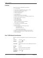
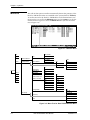
1
Dual T1/PRI Module
User Manual
Part Number 1200314L1
61200314L1-1B
May 2000
TRADEMARKS
DMS 100 is a registered trademark of Northern Telecom.
5ESS is a registered trademark of AT&T.
AT&T is a registered trademark.
901 Explorer Boulevard
P.O. Box 140000
Huntsville, AL 35814-4000
(256) 963-8000
© 2000 ADTRAN, Inc.
All Rights Reserved.
Printed in U.S.A.
FCC regulations require that the following information be provided in this manual to the
customer:
1.
2.
3.
4.
5.
6.
7.
This equipment complies with Part 68 of the FCC rules. The required label is affixed to the bottom
of the chassis.
An FCC-compliant telephone cord and modular plug is provided with this equipment. This equipment is designed to be connected to the telephone network or premises wiring using a compatible
modular jack which is Part 68-compliant. See Chapter 2, Installation, for details.
If your telephone equipment (Dual T1/PRI Module) causes harm to the telephone network, the
telephone company may discontinue your service temporarily. If possible, they will notify you in
advance. But if advance notice isn’t practical, you will be notified as soon as possible. You will be
advised of your right to file a complaint with the FCC.
Your telephone company may make changes in its facilities, equipment, operations, or procedures
that could affect the proper operation of your equipment. If they do, you will be given advance notice to give you an opportunity to maintain uninterrupted service.
If you experience trouble with this equipment (Dual T1/PRI Module), please contact ADTRAN at
(256) 963-8000 for repair/warranty information. The telephone company may ask you to disconnect this equipment from the network until the problem has been corrected or until you are sure
the equipment is not malfunctioning.
This unit contains no user-serviceable parts.
The following information may be required when applying to your local telephone company for
leased line facilities.
Service Type
REN/SOC
FIC
USOC
1.544 Mbps - SF
6.0N
04DU9-BN
RJ-48C
1.544 Mbps - SF and B8ZS
6.0N
04DU9-DN
RJ-48C
1.544 Mbps - ESF
6.0N
04DU9-1KN
RJ-48C
1.544 Mbps - ESF and B8ZS
6.0N
04DU9-1SN
RJ-48C
ISDN
6.0N
04DU9-ISN
RJ-48C
Federal Communications Commission (FCC) Radio Frequency Interference Statement
This equipment has been tested and found to comply with the limits for a Class A digital device, pursuant to Part 15 of the FCC Rules. These limits are designed to provide reasonable protection against
harmful interference when the equipment is operated in a commercial environment. This equipment
generates, uses, and can radiate radio frequency energy and, if not installed and used in accordance
with the instruction manual, may cause harmful interference to radio frequencies. Operation of this
equipment in a residential area is likely to cause harmful interference in which case the user will be required to correct the interference at his own expense.
Shielded cables must be used with this unit to ensure compliance with Class A FCC limits.
Change or modifications to this unit not expressly approved by the party responsible for compliance
could void the user’s authority to operate the equipment.
iii
Affidavit Requirements for Connection to Digital Services
•
An affidavit is required to be given to the telephone company whenever digital terminal equipment
without encoded analog content and billing protection is used to transmit digital signals containing
encoded analog content which are intended for eventual conversion into voiceband analog signals
and transmitted on the network.
•
The affidavit shall affirm that either no encoded analog content or billing information is being
transmitted or that the output of the device meets Part 68 encoded analog content or billing protection specifications.
•
End user/customer will be responsible for filing an affidavit with the local exchange carrier when
connecting unprotected customer premise equipment (CPE) to 1.544 Mbps or subrate digital services.
•
Until such time as subrate digital terminal equipment is registered for voice applications, the affidavit requirement for subrate services is waived.
Affidavit for Connection of Customer Premises Equipment
to 1.544 Mbps and/or Subrate Digital Services
For the work to be performed in the certified territory of ________________________(telco name)
State of ________________
County of ________________
I, _____________________________ (name), __________________________________(business address),
____________________ (telephone number) being duly sworn, state:
I have responsibility for the operation and maintenance of the terminal equipment to be connected to
1.544 Mbps and/or ________ subrate digital services. The terminal equipment to be connected complies
with Part 68 of the FCC rules except for the encoded analog content and billing protection specifications. With respect to encoded analog content and billing protection:
( ) I attest that all operations associated with the establishment, maintenance, and adjustment of the
digital CPE with respect to analog content and encoded billing protection information continuously complies with Part 68 of the FCC Rules and Regulations.
( ) The digital CPE does not transmit digital signals containing encoded analog content or billing
information which is intended to be decoded within the telecommunications network.
( ) The encoded analog content and billing protection is factory set and is not under the control of the
customer.
I attest that the operator(s)/maintainer(s) of the digital CPE responsible for the establishment, maintenance, and adjustment of the encoded analog content and billing information has (have) been trained
to perform these functions by successfully having completed one of the following (check appropriate
blocks):
( ) A. A training course provided by the manufacturer/grantee of the equipment used to encode
analog signals; or
( ) B. A training course provided by the customer or authorized representative, using training materials and instructions provided by the manufacturer/grantee of the equipment used to encode
analog signals; or
iv
( ) C. An independent training course (e.g., trade school or technical institution) recognized by the
manufacturer/grantee of the equipment used to encode analog signals; or
( ) D. In lieu of the preceding training requirements, the operator(s)/maintainer(s) is (are) under the
control of a supervisor trained in accordance with _________ (circle one) above.
I agree to provide ______________________ (telco’s name) with proper documentation to demonstrate
compliance with the information as provided in the preceding paragraph, if so requested.
_________________________________Signature
_________________________________Title
_________________________________ Date
Transcribed and sworn to before me
This ________ day of ________, ________
_________________________________
Notary Public
My commission expires:
_________________________________
v
Canadian Equipment Limitations
The Industry Canada Certification label identifies certified equipment. This certification means
that the equipment meets certain telecommunications network protective, operational, and safety
requirements. The Department of Commerce does not guarantee the equipment will operate to the
user's satisfaction.
Before installing this equipment, users should ensure that it is permissible to be connected to the facilities of the local telecommunications company. The equipment must also be installed using an acceptable method of connection. In some cases, the company's inside wiring associated with a single line
individual service may be extended by means of a certified connector assembly (telephone extension
cord). The customer should be aware that compliance with the above conditions may not prevent degradation of service in some situations.
Repairs to certified equipment should be made by an authorized Canadian maintenance facility designated by the supplier. Any repairs or alterations made by the user to this equipment, or equipment malfunctions, may give the telecommunications company cause to request the user to disconnect the
equipment.
Users should ensure for their own protection that the electrical ground connections of the power utility,
telephone lines and internal metallic waterpipe system, if present, are connected together. This precaution may be particularly important in rural areas.
Users should not attempt to make such connections themselves, but should contact the appropriate
electric inspection authority, or an electrician, as appropriate.
The Load Number (LN) assigned to each terminal device denotes the percentage of the total load to be
connected to a telephone loop which is used by the device, to prevent overloading. The termination on
a loop may consist of any combination of devices subject only to the equipment that the total of the LNs
of all devices does not exceed 100.
The ringer equivalence number (REN) assigned to each terminal adapter is used to determine the total
number of devices that may be connected to each circuit. The sum of the RENs from all devices in the
circuit should not exceed a total of 5.0.
Warranty and Customer Service
ADTRAN will replace or repair this product within five years from the date of shipment if the product
does not meet its published specification, or if it fails while in service. For detailed warranty, repair, and
return information, refer to the ADTRAN Equipment Warranty and Repair and Return Policy Procedure (see the last page of this manual).
A return material authorization (RMA) is required prior to returning equipment to ADTRAN.
For service, RMA requests, or more information, see the last page of this manual for the toll-free contact
number.
vi
Limited Product Warranty
ADTRAN warrants that for five (5) years from the date of shipment to Customer, all products manufactured by ADTRAN will be free from defects in materials and workmanship. ADTRAN also warrants
that products will conform to the applicable specifications and drawings for such products, as contained in the Product Manual or in ADTRAN's internal specifications and drawings for such products
(which may or may not be reflected in the Product Manual). This warranty only applies if Customer
gives ADTRAN written notice of defects during the warranty period. Upon such notice, ADTRAN will,
at its option, either repair or replace the defective item. If ADTRAN is unable, in a reasonable time, to
repair or replace any equipment to a condition as warranted, Customer is entitled to a full refund of the
purchase price upon return of the equipment to ADTRAN. This warranty applies only to the original
purchaser and is not transferable without ADTRAN's express written permission. This warranty becomes null and void if Customer modifies or alters the equipment in any way, other than as specifically
authorized by ADTRAN.
EXCEPT FOR THE LIMITED WARRANTY DESCRIBED ABOVE, THE FOREGOING CONSTITUTES
THE SOLE AND EXCLUSIVE REMEDY OF THE CUSTOMER AND THE EXCLUSIVE LIABILITY OF
ADTRAN AND IS IN LIEU OF ANY AND ALL OTHER WARRANTIES (EXPRESSED OR IMPLIED).
ADTRAN SPECIFICALLY DISCLAIMS ALL OTHER WARRANTIES, INCLUDING (WITHOUT LIMITATION), ALL WARRANTIES OF MERCHANTABILITY AND FITNESS FOR A PARTICULAR PURPOSE. SOME STATES DO NOT ALLOW THE EXCLUSION OF IMPLIED WARRANTIES, SO THIS
EXCLUSION MAY NOT APPLY TO CUSTOMER.
In no event will ADTRAN or its suppliers be liable to Customer for any incidental, special, punitive,
exemplary or consequential damages experienced by either Customer or a third party (including, but
not limited to, loss of data or information, loss of profits, or loss of use). ADTRAN is not liable for damages for any cause whatsoever (whether based in contract, tort, or otherwise) in excess of the amount
paid for the item. Some states do not allow the limitation or exclusion of liability for incidental or consequential damages, so the above limitation or exclusion may not apply to Customer.
vii
viii
Table of Contents
List of Figures ..................................................................................................................................................... xi
List of Tables.....................................................................................................................................................xiii
Chapter 1
Introduction .............................................................................................................................. 1-1
Dual T1/PRI Module Overview ..................................................................................................................... 1-1
Functional Description ..................................................................................................................................... 1-1
Features ....................................................................................................................................................... 1-2
Dual T1/PRI Module Specifications ....................................................................................................... 1-2
Physical Description ......................................................................................................................................... 1-3
Chapter 2
Installation ................................................................................................................................ 2-1
Before Installing the Dual T1/PRI Module ................................................................................................... 2-1
Shipping Contents ..................................................................................................................................... 2-1
Installing the Dual T1/PRI Module ............................................................................................................... 2-1
Wiring ................................................................................................................................................................. 2-3
Chapter 3
Operation .................................................................................................................................. 3-1
Overview ............................................................................................................................................................ 3-1
Terminal Menu Structure................................................................................................................................. 3-1
Modules .............................................................................................................................................................. 3-2
Slt ................................................................................................................................................................. 3-3
Type ............................................................................................................................................................ 3-3
Menu ........................................................................................................................................................... 3-3
Alarm .......................................................................................................................................................... 3-3
Test .............................................................................................................................................................. 3-3
State ............................................................................................................................................................. 3-3
Status .......................................................................................................................................................... 3-4
Online .................................................................................................................................................. 3-4
No Response ....................................................................................................................................... 3-4
Empty .................................................................................................................................................. 3-4
Offline .................................................................................................................................................. 3-4
Offline/No Response ........................................................................................................................ 3-4
Rev .............................................................................................................................................................. 3-4
Modules/ T1/PRI Menus ................................................................................................................................ 3-4
Info .............................................................................................................................................................. 3-5
Part Number ....................................................................................................................................... 3-5
Serial Number .................................................................................................................................... 3-5
Assembly Revision ............................................................................................................................ 3-5
PLL Status ........................................................................................................................................... 3-5
Alarm Status .............................................................................................................................................. 3-5
Prt ......................................................................................................................................................... 3-5
61200314L1-1
Dual T1/PRI Module User Manual
ix
Table of Contents
Alarms ................................................................................................................................................. 3-5
LOS ............................................................................................................................................... 3-5
Red ................................................................................................................................................ 3-5
Yellow ........................................................................................................................................... 3-5
Blue ............................................................................................................................................... 3-5
DS0 Alarm ................................................................................................................................... 3-5
Rx Level .............................................................................................................................................. 3-5
DS0 Status .................................................................................................................................................. 3-6
DS0 Alarms ................................................................................................................................................ 3-6
Sig Status .................................................................................................................................................... 3-6
Performance Current ................................................................................................................................ 3-7
PRT ....................................................................................................................................................... 3-7
CLR ...................................................................................................................................................... 3-7
ES .......................................................................................................................................................... 3-7
BES ....................................................................................................................................................... 3-7
SES ........................................................................................................................................................ 3-7
SEFS ..................................................................................................................................................... 3-7
LOFC .................................................................................................................................................... 3-7
CSS ....................................................................................................................................................... 3-7
UAS ...................................................................................................................................................... 3-7
LCV ...................................................................................................................................................... 3-7
PCV ...................................................................................................................................................... 3-7
LES ....................................................................................................................................................... 3-7
Performance 15Min ................................................................................................................................... 3-7
Performance 24hr ...................................................................................................................................... 3-7
Configuration ............................................................................................................................................ 3-7
Prt ......................................................................................................................................................... 3-7
Port Name ........................................................................................................................................... 3-7
Frame ................................................................................................................................................... 3-8
Code ..................................................................................................................................................... 3-8
Tx Yel ................................................................................................................................................... 3-8
Tx PRM ................................................................................................................................................ 3-8
LBO ...................................................................................................................................................... 3-8
LB Accept ............................................................................................................................................ 3-8
Pulse Density ...................................................................................................................................... 3-8
Test .............................................................................................................................................................. 3-8
Prt ......................................................................................................................................................... 3-9
Loc LB .................................................................................................................................................. 3-9
Remote LB ........................................................................................................................................... 3-9
Pattern ................................................................................................................................................. 3-9
QRSS/RLB Results .......................................................................................................................... 3-10
CLR .................................................................................................................................................... 3-10
INJ ...................................................................................................................................................... 3-10
ATLAS 550 Features Used with Dual T1/PRI Module ............................................................................. 3-10
Factory Restore ................................................................................................................................................ 3-10
Run Self Test .................................................................................................................................................... 3-10
Mapping ........................................................................................................................................................... 3-11
Appendix A Dial Plan Interface Configuration ...................................................................................... A-1
Index ...........................................................................................................................................................Index-1
x
Dual T1/PRI Module User Manual
61200314L1-1
List of Figures
Figure 1-1.
Figure 2-1.
Figure 3-1.
Figure 3-2.
Figure 3-3.
Figure 3-4.
Figure A-1.
Dual T1/PRI Module .................................................................................................................. 1-3
Installing the Dual T1/PRI Module.......................................................................................... 2-2
Modules Menu............................................................................................................................. 3-2
Menu Tree for Dual T1/PRI Modules Menu .......................................................................... 3-2
Dual T1/PRI Module Menu Options ....................................................................................... 3-4
Network Loopback Test ............................................................................................................. 3-9
Dial Plan Menus ......................................................................................................................... A-1
61200314L1-1
Dual T1/PRI Module User Manual
xi
List of Figures
xii
Dual T1/PRI Module User Manual
61200314L1-1
List of Tables
Table 2-1.
Network Connection Pinout...................................................................................................... 2-3
61200314L1-1
Dual T1/PRI Module User Manual
xiii
List of Tables
xiv
Dual T1/PRI Module User Manual
61200314L1-1
Chapter 1
Introduction
DUAL T1/PRI MODULE OVERVIEW
The Dual T1/PRI Module (P/N 1200314L1) is a member of the ATLAS 550
family of integrated access products and provides two channelized T1 or
Primary Rate ISDN (PRI) interfaces. Each interface can operate independently in DS-1 or DSX-1 mode, and any port can serve as the primary or backup
timing source for the entire system.
The Dual T1/PRI Module combines with the ATLAS 550 Base Unit and other ATLAS 550 modules to support requirements calling for multiple T1 and/
or PRI circuits. You can install into the system as many Dual T1/PRI Modules as can be physically accommodated in the ATLAS 550 chassis.
Typical applications calling for ATLAS 550 and the Dual T1/PRI Module include the following:
•
Digital Access Cross Connect System (DACS). Any DS0 on any T1 circuit can be switched to any other DS0 on any other T1 circuit.
•
T1 Bandwidth Management. T1 circuits carrying voice, data, video, and
other traffic can have their payload groomed and directed to the appropriate interface inside the ATLAS 550 system (see Figure 1-1).
•
ISDN Access Switch. When combined with the Quad BRI/U Module
P/N 1200315L1), the Dual T1/PRI Module can combine multiple Basic Rate
ISDN (BRI) circuits onto one or more Primary Rate ISDN (PRI) circuits.
FUNCTIONAL DESCRIPTION
The Dual T1/PRI Module installs into any available option slot in the
ATLAS 550 chassis. You can view the status of the module itself, as well as
the circuits to which it interfaces, from the ATLAS 550 terminal menu,
accessible through either a VT-100 terminal connected to the ATLAS 550
Base Unit’s control port or through a Telnet session established through the
Base Unit’s Ethernet port. Use the terminal menu to configure the Dual T1/
PRI Module.
61200314L1-1
Dual T1/PRI Module User Manual
1-1
Chapter 1. Introduction
Features
Features of the Dual T1/PRI Module are listed here:
•
Two T1 interfaces
•
Each interface configurable for DS-1, DSX-1, or PRI
•
AT&T 62411 and ANSI T1.403 compliant
•
Diagnostic loopback support
•
Various timing options
•
T1 ESF diagnostics
•
Bantum monitor jacks on each interface
•
Performance per ANSI T1.403, AT&T 54016, and ANSI T1.102
•
RJ-48C network interface connector
•
AMI or B8ZS coding
•
ESF or SF(D4) framing
•
Line build-out settings:
DSX-1: 0 to 655 feet in 133-foot increments
DS-1: -22.5, -15, -7.5, and 0 dB
•
Line loopback (VT-100/remote/in-band)
•
Payload loopback
•
PRI switch support for the following switches:
-
ATT 5ESS NT or LT
-
Nortel DMS-100 NT or LT
-
NI-2 NT (network termination)
•
Supports the inherent DACS capability of the ATLAS 550
•
Reports line performance data via SNMP in RFC1406 format
•
Trunk conditioning
Dual T1/PRI Module Specifications
Each port of the Dual T1/PRI Module conforms to the following specifications:
1-2
Line rate
1.544 Mbps, + 75 bps
Capacity
T1: 1 to 24 DS0s
PRI: 23 B + D
Line Codes
AMI (alternate mark inversion) or B8ZS (bipolar return to
zero)
Framing
D4 or ESF
Tests
Self-test, line loopback, port loopback
Connectors
RJ-48C (eight-position modular jack)
Terminating
Impedance
100 ohms + 5%
Dual T1/PRI Module User Manual
61200314L1-1
Chapter 1. Introduction
PHYSICAL DESCRIPTION
The Dual T1/PRI Module (see Figure 1-1) plugs into any available option
slot in the rear of the ATLAS 550 chassis.
The four Option slots (labeled 1 — 4) only accept Option Modules,
and the Network Interface slots (labeled Network 1 and Network 2)
only accept Network Interface Modules. (See the ATLAS 550 in
Figure 2-1 on page 2-2.)
1
DUAL T1 / PRI
MON
500 Series
2
Figure 1-1. Dual T1/PRI Module
The Dual T1/PRI Module design includes a label above each RJ-48C connector identifying the port on the card. Each port comes with an RJ-48C connector for the T1 circuit interface and a single Bantam plug for monitoring
received data.
61200314L1-1
Dual T1/PRI Module User Manual
1-3
Chapter 1. Introduction
1-4
Dual T1/PRI Module User Manual
61200314L1-1
Chapter 2
Installation
BEFORE INSTALLING THE DUAL T1/PRI MODULE
Carefully unpack and inspect the Dual T1/PRI Module for shipping damages. If you suspect damage occurred during shipping, file a claim immediately with the carrier and then contact ADTRAN Technical Support (see the last
page of this manual for pertinent information). If possible, keep the original
shipping container for returning the Dual T1/PRI Module for repair or for
verification of shipping damage.
Shipping Contents
The ADTRAN shipment includes the following items:
•
Dual T1/PRI Module
•
Dual T1/PRI Module User Manual (insert into the ATLAS 550 User
Manual)
•
Two cables (RJ-48C to RJ-48C), ADTRAN P/N: 3125M008
•
One crossover cable (RJ-48C to RJ-48C), ADTRAN P/N: 3125M010
INSTALLING THE DUAL T1/PRI MODULE
Figure 2-1 on page 2-2 represents the action required to properly install the
Dual T1/PRI Module, as described in the Step/Action table on page 2-2.
The four Option slots (labeled 1 — 4) only accept Option Modules,
and the Network Interface slots (labeled Network 1 and Network 2)
only accept Network Interface Modules. (See the ATLAS 550 in
Figure 2-1 on page 2-2.)
61200314L1-1
Dual T1/PRI Module User Manual
2-1
Chapter 2. Installation
Instructions for Installing the Dual T1/PRI Module
Step
Action
1
Remove the cover plate from the appropriate option slot of the
ATLAS 550 rear panel.
2
Slide the Dual T1/PRI Module into the option slot until the
module is firmly seated against the front of the chassis.
3
Secure the thumbscrews at both edges of the module. Tighten
with a screwdriver.
4
Connect the cables to the associated device(s).
5
Complete installation of remaining modules and Base Unit as
specified in the Installation chapter of the ATLAS 550 User
Manual.
Remove Cover Plate
O
O I
I
4
2
ALL EMPTY SLOTS MUST BE
COVERED WITH BLANK PANELS
1
DUAL T1 / PRI
MON
500 Series
2
NETWORK 2
NETWORK 1
FUSE RATING: 2A/250V SLO-BLO
ETHERNET
CONTROL
IN
OUT
RELAY
MON
CAUTION: FOR CONTINUED PROTECTION
AGAINST RISK OF FIRE, REPLACE ONLY
WITH SAME TYPE AND RATING OF FUSE.
90-240VAC, 2A, 50/60Hz
ALARM
NC NO COM GND
Figure 2-1. Installing the Dual T1/PRI Module
Option modules are intended to be serviced by qualified service
personnel only.
2-2
Dual T1/PRI Module User Manual
61200314L1-1
Chapter 2. Installation
WIRING
Each port of the Dual T1/PRI Module uses a single, eight-position modular
jack to connect to the T1 or PRI circuit. Tabl e2-1 gives the pinout for this
jack. The required wiring connection is described here:
Connector Type
(USOC) RJ-48C
Table 2-1. Network Connection Pinout
PIN
61200314L1-1
NAME
DESCRIPTION
1
R1 RXDATA
Receive data from the network ring
2
T1 RXDATA
Receive data from the network tip
3
UNUSED
—
4
R TXDATA
Send data towards the network ring
5
T TXDATA
Send data towards the network tip
6,7,8
UNUSED
—
Dual T1/PRI Module User Manual
2-3
Chapter 2. Installation
2-4
Dual T1/PRI Module User Manual
61200314L1-1
Chapter 3
Operation
OVERVIEW
You can configure and control the Dual T1/PRI Module from a variety of
sources, including the following:
•
The terminal menu, allowing detailed configuration, status, and diagnostics
•
SNMP, primarily for reporting alarm conditions and system status
The remainder of this chapter describes the menu items available when
managing the Dual T1/PRI Module via the terminal menu.
Access the terminal menu using either a VT-100 terminal attached to the
ATLAS 550 Base Unit’s control port or a Telnet session established through
the Base Unit’s Ethernet port. The ATLAS 550 User Manual provides detailed
instructions on the operation of each of these management approaches.
To edit items in the terminal menu, you must have the appropriate
password level. Each menu description in this section indicates
the password level required for write and read access. See “Access
Passwords” in the ATLAS 550 User Manual for detailed
information on working with passwords.
Security level 0 users can view and edit every available field.
Security level 5 users can view any field but cannot edit.
TERMINAL MENU STRUCTURE
The ATLAS 550 uses a hierarchical menu structure to provide access to all of
its features. The top-most menu level leads to submenus which are grouped
by functionality. All menu items display in the terminal window. To access
the Dual T1/PRI Module, activate the MODULES menu. The following sections describe the menu items for the Dual T1/PRI Module which are located in the MODULES menu.
Refer to the ATLAS 550 User Manual for detailed instructions
on navigating through the terminal menu.
61200314L1-1
Dual T1/PRI Module User Manual
3-1
Chapter 3. Operation
MODULES
The ATLAS 550 system controller automatically detects the presence of the
Dual T1/PRI Module when it is installed in the system (listed as T1/PRI-2).
To see the menus for the Dual T1/PRI Module via the terminal menu, use
the arrow keys to scroll to the MODULES menu and press Enter to access the
module choices. Figure 3-1 shows the MODULES menu (see also the menu
tree in Figure 3-2).
Figure 3-1. Modules Menu
Slt
Part Number
Type
Info
Serial Number
T1/PRI-2 Menus
Assembly Revision
PLL Status
Menu
Module Alarms
LOS
Alarm Status
Prt
Red
(shortcut)
Alarms
Yellow
Rx Level
Prt
Modules
Alarm
DS0 Status
CLR
DS0 Alarms
ES
Sig Status
BES
Test
SES
State
Performance Curr,
15Min, and 24Hr
Status
Blue
DS0 Alarm
Rev
Prt
SEFS
Port Name
LOFC
Frame
CSS
Code
UAS
Tx Yel
LCV
Tx PRM
PCV
LBO
LES
LB Accept
Configuration
Pulse Density
Prt
Loc LB
Test Activity
Remote LB
(shortcut)
Pattern
Test
Clr
QRSS/RLB Results
Inj
Figure 3-2. Menu Tree for Dual T1/PRI Modules Menu
3-2
Dual T1/PRI Module User Manual
61200314L1-1
Chapter 3. Operation
SLT
Read security: 5
Displays the slot number for available option slots in the ATLAS 550 chassis. Slot 0 refers to the ATLAS 550 Base Unit. This field is read-only.
TYPE
Write security: 3; Read security: 5
Displays the type of module currently installed in the slot or the type of
module you plan to install in the slot. If a Dual T1/PRI Module is installed,
the TYPE field automatically defaults to T1/PRI.
You can use this field to preconfigure a system before actually installing
modules by simply specifying the module that you want to install in each
slot. If you intentionally leave a slot empty, mark it as EMPTY to avoid getting a Not Responding message.
TYPE automatically displays the name of an installed module. If
you want to preconfigure the slot for a different type of module,
you must set this field to EMPTY before selecting another module
type.
MENU
Displays additional status and configuration menus for the selected module.
(To access the submenus for this item, use the arrow keys to scroll to the
MENU column for the module you want to edit, and press Enter.) For detailed
information on each submenu item, see Modules/ T1/PRI Menus on page 3-4.
ALARM
Read security: 5
Displays an alarm condition on the Dual T1/PRI Module. Press Enter in this
field to activate the ALARM menu.
TEST
Read security: 5
Displays tests that the Dual T1/PRI Module is executing. Press Enter in this
field to activate the TEST menu.
STATE
Write security: 3; Read security: 5
Indicates the module status, either ONLINE or OFFLINE. Even though a module is physically installed, it must be marked ONLINE to be considered an
available resource. You can mark an installed module OFFLINE, which may
be useful in system troubleshooting. If you choose OFFLINE, the module will
not be in alarm condition, but will display OFFLINE.
A module must be in the ONLINE state in order for ATLAS 550 to
use the module for any data bandwidth.
61200314L1-1
Dual T1/PRI Module User Manual
3-3
Chapter 3. Operation
STATUS
Read security: 5
Read-only field that presents status information on the Dual T1/PRI Module.
The following messages may display:
ONLINE
The module is enabled and is responding to the system controller’s status
polls. This is the normal response of the system.
NO RESPONSE
The module is enabled, but is not responding to the system controller’s status polls. This response indicates either a problem in the system or that the
module is not installed.
EMPTY
The system controller has not detected the presence of a module in the slot,
nor has a module been manually enabled for this option slot.
OFFLINE
The module is installed, but has been taken Offline by a user. The module is
still responding to controller polls.
OFFLINE/NO
RESPONSE
The module is installed, but has been taken Offline by a user. The module is
not responding to controller polls.
REV
Read security: 5
Read-only field that displays the assembly revision of the Dual T1/PRI
Module.
MODULES/ T1/
PRI MENUS
Figure 3-3 shows the MODULES/T1/PRI MENUS options. The following sections describe these menu options. (Refer also to the menu tree shown in Figure 3-2.)
Figure 3-3. Dual T1/PRI Module Menu Options
3-4
Dual T1/PRI Module User Manual
61200314L1-1
Chapter 3. Operation
INFO
Read security: 5
Provides information about the module part number, serial number, assembly revision, and PLL status.
PART NUMBER
Displays the part number of the module.
SERIAL NUMBER
Displays the serial number of the module.
ASSEMBLY
REVISION
Displays the assembly revision.
PLL STATUS
Indicates whether the clock is locked to its specific source.
ALARM STATUS
Read security: 5
Displays the current T1 alarm status.
PRT
Indicates the port number.
ALARMS
Read security: 5
Displays an alarm condition on the ATLAS 550 unit. Press ENTER to access
this menu item.
LOS
Indicates a loss of signal detected on port interface.
RED
Indicates inability to frame data received on the port. Alternately referred to
as Out of Frame (OOF).
YELLOW
Receiving remote alarm (RAI) on port.
BLUE
Receiving unframed all ones from the port Alarm Indicator Signal (AIS).
DS0 ALARM
Displays per-DS0 alarm status; that is, at least one DS0 channel is in alarm if
an asterisk (*) appears. These alarms usually indicate the failure to receive
the protocol that has been configured for the DS0.
RX LEVEL
61200314L1-1
(Receive Level) Indicates the strength of the signal (in dB) received on the
port.
Dual T1/PRI Module User Manual
3-5
Chapter 3. Operation
DS0 STATUS
DS0 ALARMS
SIG STATUS
3-6
Read security: 5
The DS0 status indicates usage on a DS0 basis for each port. These options
are read-only:
-
Unallocated
*
Inactive
+
Signaling mismatch
A
Active B Channel
D
Active D Channel
M
Maintenance
N
Dedicated (nailed)
O
Off hook - originate (RBS)
R
Ringing (RBS); Restart (ISDN)
W
Waiting dial tone
Read security: 5
Displays per-DS0 alarm status. These alarms usually indicate the failure to
receive the protocol that has been configured for the DS0.
-
No Alarm DS0
D
D Channel Alarm (ISDN)
F
Frame Alarm (PACKET)
T
TBOP Alarm (PACKET)
Read security: 5
Read-only field indicates signaling of all 24 DS0s. The A/B bits for Rx
(receive) and Tx (transmit) DS0s are shown for each port. Dashes display
for those DS0s where robbed bit signaling (RBS) is not being transferred by
the ATLAS 550.
Dual T1/PRI Module User Manual
61200314L1-1
Chapter 3. Operation
PERFORMANCE
CURRENT
Write security: 3; Read security: 5
The performance fields (either current, 15-minute total, or 24-hour total)
provide status on key performance measures as specified in ANSI T1.403
and AT&T TR54016 for each of the two T1/PRI ports. Excepting CLR, these
fields are all read-only. The monitored parameters include the following:
PRT
Displays the port number.
CLR
Clears performance information for the selected port.
ES
An Errored Seconds (ES) is a second with one or more error events OR one
or more Out Of Frame events OR one or more Controlled Slips.
BES
A Bursty Errored Seconds (BES) is a second with more than one, but less
than 320 error events.
SES
A Severely Errored Second (SES) is a second with 320 or more error events
OR one or more Out Of Frame events.
SEFS
Severely Errored Frame Seconds.
LOFC
Loss of Frame Count.
CSS
Controlled Slip Seconds.
UAS
Unavailable Seconds.
LCV
Line Code Violations.
PCV
Path Code Violations.
LES
Line Errored Seconds.
PERFORMANCE
15MIN
Write security: 3; Read security: 5
Stores the performance data for the previous 15-minute window. Refer to
Performance Current for a detailed description of these fields.
PERFORMANCE 24HR Write security: 3; Read security: 5
Stores the performance data for the previous 24-hour window. Refer to Performance Current for a detailed description.
CONFIGURATION
All of the following configurable parameters apply to whether the port is
connected to a Primary Rate ISDN circuit or a channelized T1 circuit.
PRT
Read security: 5
Displays the port number.
PORT NAME
Write security: 3; Read security: 5
Accepts any alpha-numeric name up to 16 characters long, to uniquely
identify each port on the Dual T1/PRI Module.
61200314L1-1
Dual T1/PRI Module User Manual
3-7
Chapter 3. Operation
TEST
FRAME
Write security: 2; Read security: 5
This field must be set to match the frame format of the circuit to which it is
connected, available from the network supplier. Choose either D4 or ESF.
CODE
Write security: 2; Read security: 5
Set this field to match the line code of the circuit to which it is connected
(this information is available from the network supplier). Choose either
AMI or B8ZS.
TX YEL
Write security: 3; Read security: 5
Controls the transmitting of yellow alarms. Choose either ON or OFF.
TX PRM
Write security: 3; Read security: 5
Controls the sending of performance report messaging (PRM) data on the
facility data link (FDL). The PRM data continues to be collected even if
XMIT PRM is turned off (possible only with ESF format). Choose either ON
or OFF.
LBO
Write security: 2; Read security: 5
Selects the Line Build Out (LBO) for the network interface. When connecting a Dual T1/PRI Module port to a DSX-1 interface, this parameter is typically set to match the distance (in feet) between the ATLAS 550 and the
device with which it is connecting. When you select this item, a list of
choices displays. Select the appropriate option.
LB ACCEPT
Write security: 3; Read security: 5
Sets unit to accept or reject the in-band loop up and loop down codes as
defined in ANSI T1.403. This is a line loopback. Choose either ACCEPT or
IGNORE.
PULSE DENSITY
Write security: 3; Read security: 5
Choose either ON or OFF. When ON, Pulse Density Enforcer causes the
ATLAS 550 to monitor for ones (1s) density violations and insert a one (1)
when needed to maintain ones at 12.5% This data insertion will cause data
errors.
These options initiate different types of tests and display test results.
These test commands temporarily disrupt service.
3-8
Dual T1/PRI Module User Manual
61200314L1-1
Chapter 3. Operation
PRT
Read security: 5
Displays the port number.
LOC LB
Write security: 4; Read security: 5
Causes loopback on near-end (local) port (see Figure 3-4). The following
options are available:
Line
Metallic loopback
Payld
Payload loopback - framing and clocking are regenerated
Dual T1/PRI
NI CSU
DS1
Payload Loopback
Line Loopback
Figure 3-4. Network Loopback Test
REMOTE LB
PATTERN
61200314L1-1
Write security: 4; Read security: 5
Sends loopback code to Remote CSU. The following options are available:
ANSI FDL Line
Requires ESF mode.
ANSI FDL Pyld
Requires ESF mode.
AT&T Inband line
Works in ESF and D4 mode.
Write security: 4; Read security: 5
Test pattern to be transmitted out the port. The following options are available:
All ones
Framed ones
All zeros
Framed zeros
QRSS
Pseudo-random pattern with suppression of excess zeros
Dual T1/PRI Module User Manual
3-9
Chapter 3. Operation
QRSS/RLB
RESULTS
Write security: 4; Read security: 5
Displays current status of T1 tests including information regarding loopbacks and test patterns. When displaying tests pattern status, the display
string is composed of pattern sync status, and errored seconds.
None
No sync.
LOS
Sync has been lost.
Sync
Pattern is synchronized.
ES
Number of seconds with at least one bit error.
CLR
Write security: 3; Read security: 5
Clears error counters on test pattern results menu.
INJ
Write security: 3; Read security: 5
Injects errors into transmitted test pattern.
ATLAS 550 FEATURES USED WITH DUAL T1/PRI MODULE
In addition to the Dual T1/PRI Module menu items, two additional ATLAS
550 menu items may be operated in conjunction with the Dual T1/PRI Module. These are FACTORY RESTORE and RUN SELF TEST.
FACTORY
RESTORE
FACTORY RESTORE restores the factory-installed default setting for all Dual
T1/PRI Module parameters. When “Factory Restore” displays, place the
cursor on it and press Enter. The unit is restored to preset factory defaults
and returns to the main ATLAS 550 menu.
RUN SELF TEST
RUN SELF TEST, a submenu of the ATLAS 550 main menu item TEST, executes the ATLAS 550 internal test for the Dual T1/PRI Module. For additional information on SELF TEST see the ATLAS 550 User Manual.
3-10
Dual T1/PRI Module User Manual
61200314L1-1
Chapter 3. Operation
MAPPING
DS0s are used as defined in the DEDICATED MAP or in the DIAL PLAN for
switched applications. (See the ATLAS 550 User Manual for a description.)
Defining a port as a T1 or PRI is determined by the way it is
assigned in the DEDICATED MAP or in the DIAL PLAN. See
Appendix A of this manual for more information on setting up the
DIAL PLAN.
61200314L1-1
Dual T1/PRI Module User Manual
3-11
Chapter 3. Operation
3-12
Dual T1/PRI Module User Manual
61200314L1-1
Appendix A
Dial Plan Interface Configuration
INTERFACE CONFIGURATION
The interface configuration option for the DIAL PLAN menu sets
configuration parameters for the endpoint. These parameters vary by the
type of port selected. This appendix describes the configuration options
available for the ATLAS 550. To access these options, select DIAL PLAN from
the top-level ATLAS 550 menu (see Figure A-1).
Figure A-1. Dial Plan Menus
DUAL T1/PRI MODULE INTERFACE CONFIGURATION
The remainder of this appendix discusses the following network termination and user termination configuration settings for the ATLAS 550 when using the DIAL PLAN menus:
61200314L1-1
•
Dual T1/PRI Module: Network Termination/PRI on page A-2
•
Dual T1/PRI Module: Network Termination/RBS on page A-5
•
Dual T1/PRI Module: User Termination/PRI on page A-8
•
Dual T1/PRI Module: User Termination/RBS on page A-10
Dual T1/PRI Module User Manual
A-1
Appendix A. Dial Plan Interface Configuration
DUAL T1/PRI MODULE: NETWORK TERMINATION/PRI
When you are working in the network termination section of the DIAL PLAN
menu, when SLT is defined as T1/PRI-2, and when SIG is set to PRI, the following configuration options are available:
SWITCH TYPE
Write security: 3; Read security: 5
Defines the type of PRI switch to which the port is connected. If connected
to another ATLAS 550, both need to be set to the same switch type. The following options are available:
•
•
Lucent 5E
National ISDN
•
•
Northern DMS 100
AT&T 4ESS
FIRST DS0
Write security: 3; Read security: 5
Defines to the ATLAS 550 the first DS0 for this endpoint.The ATLAS 550
uses DS0s, starting with this selection, to send and receive calls to and from
the network (PSTN). The outgoing calls which are allowed or restricted
over these DS0s are set by the OUTGOING CALL ACCEPT and REJECT NUMBERS (discussed in the ATLAS 550 User Manual).
NUMBER OF DS0S
Write security: 3; Read security: 5
Specifies the number of DS0s ATLAS 550 uses for this endpoint.
OUTGOING
NUMBER
CONVERSION
Write security: 3; Read security: 5
Converts outgoing (towards the network) numbers to the selected numbering plan and type option.
AS DIALED
Sends the digits provided as an unknown number type.
ISDN-NATIONAL
Regardless of what type of number is received, the outgoing number is substituted with ISDN-National as the number plan and type. Ten digits are
always sent to the network. Leading ones, if present, are stripped out and
the area code (provisioned under DIAL PLAN/GLOBAL PARAMETERS) is
added, if only seven digits are supplied. This action may be required in
areas with ten-digit local dialing.
PREFERRED
ISDN-SUBSCRIBER
PREFERRED
ISDN-NATIONAL
DMS RESERVED
PREFERRED
A-2
Examines the incoming number and if seven digits are received or if a tendigit number is received with an area code that matches the area code provisioned in the global parameters, the number is forwarded to the network
as a seven-digit number defined as ISDN-Subscriber number plan and type.
If the incoming number is ten digits, but with a different area code, it is forwarded to the network as ISDN-National preferred.
Ignores the incoming numbering plan and type and substitutes the ISDN/
Telephony numbering plan and National number type. Ten digits are sent
to the network. Leading ones, if present, are stripped out and the area code
set in global parameters is added if only seven digits are supplied. This
action may be required in areas with ten-digit local dialing.
Dual T1/PRI Module User Manual
61200314L1-1
Appendix A. Dial Plan Interface Configuration
ISDN-NATIONAL AS
DIALED
Sends the digits provided as National number type.
When SWITCH TYPE is set to 4ESS, many installations require the
National form where possible; this may also be the preferred form in
10-digit calling areas.
STRIP MSD
Write security: 3; Read security: 5
Strips a selected quantity (choose from NONE, 1, 2, and 3) of the Most Significant Digits (MSD) of a dialed number prior to being forwarded out of the
port.
EXAMPLE:
A network port could be set to accept all calls beginning with 9 (9$), and
then with STRIP MSD set to 1, all digits would be sent toward the network
except the leading 9.
STRIP MSD does not affect CALL ACCEPT criteria. All of the digits
(including the MSDs that are subsequently stripped) are used as
accept criterion.
NETWORK
SPECIFIC
FACILITY VOICE
AND DATA
Write security: 3; Read security: 5
Enables the sending of appropriate information to the PSTN. The default
for this option is NORMAL, and in this case no Network Specific Facility
Information Element is sent. Unless one of the services listed below is subscribed to, the selection should remain set to NORMAL.
The list below indicates services that may be subscribed to from the PSTN.
These services require that specific information (such as a Network Specific
Facility Information Element) be sent to the network during call setup.
CALLED DIGITS
TRANSFERRED
61200314L1-1
•
AT&T SDN
•
National ISDN INWATS
•
AT&T Megacom 800
•
Nortel Private Network
–
AT&T Megacom
•
Nortel InWats
–
AT&T Accunet
•
Nortel OutWats
•
AT&T Long Distance
•
Nortel Foreign Exchange
•
AT&T International-800
•
Nortel Tie Trunk
•
AT&T Dial-It 900/Multiquest
Write security: 3; Read security: 5
Some PRI switches may be provisioned to send only a portion of the called
number (like DID). This menu item allows the ATLAS 550 to know how
many digits to expect (choose from NONE, THREE, FOUR, SEVEN, and ALL).
Dual T1/PRI Module User Manual
A-3
Appendix A. Dial Plan Interface Configuration
The default is ALL and would almost always be correct. If less than ALL digits are sent, then the PREFIX is defined as shown below.
PREFIX
Write security: 3; Read security: 5
Displays only if CALLED DIGITS TRANSFERRED is not set to ALL. Enter the
prefix for the digits received.
EXAMPLE:
If the number of digits is four and the number called is 963-8615, the telco’s
PRI switch sends only 8615 and the prefix is set to 963. This entire number is
then used to determine which ATLAS 550 User port endpoint should
receive the call.
OUTGOING
CALLER ID
Write security: 3; Read security: 5
Defines the number for the ATLAS 550 to use to provide Caller ID to the
Network for outgoing calls sent through this endpoint. Choose from SEND
AS PROVIDED, SUBSTITUTE IF NOT PRESENT, or SUBSTITUTE ALWAYS.
The Caller ID number must be specific (i.e., no “wild cards”).
SOURCE ID
Write security: 3; Read security: 5
Simplifies the creation of a DIAL PLAN in applications where the criterion for
switching calls to a certain endpoint is a function of which endpoint originated the call.
•
Default value = 0. The default ID for all endpoints is 0 and all accept
numbers is 0. With default values, all calls are routed based only on the
dialed number.
•
Multiple endpoints can have the same SOURCE ID.
•
When creating the CALL ACCEPT list, specify a SOURCE ID(s) as well as a
dialed number or range of dialed numbers to accept.
EXAMPLE:
An application requires that all calls that originate from Port 1 of the Dual
T1/PRI Module in Slot 1 be switched to Port 2 of that same module. Assign
a unique Source ID (e.g. 7) to Port 1 of the module, and then configure Port
2 to only accept calls from that unique Source ID (7).
A-4
Dual T1/PRI Module User Manual
61200314L1-1
Appendix A. Dial Plan Interface Configuration
SWAP ANI/DNIS
Write security: 3; Read security: 5
Swaps the ANI and DNIS numbers received from the network. ANI (Automatic Number Identification) is the billing number of the calling party, and
DNIS (Dialed Number Identification Service) is the called party number.
With this swap, the ATLAS 550 switchboard uses ANI to route the
call. The accept number in the Dial Plan must use the ANI number,
not the DNIS number.
DUAL T1/PRI MODULE: NETWORK TERMINATION/RBS
When you are working in the network termination section of the DIAL PLAN
menu, when SLT is defined as T1/PRI-2, and when SIG is set to RBS, the following interface configuration options are available:
FIRST DS0
Write security: 3; Read security: 5
Defines to the ATLAS 550 the first DS0 for this endpoint.The ATLAS 550
uses DS0s, starting with this selection, to send and receive calls to and from
the network (PSTN). The outgoing calls which are allowed or restricted
over these DS0s are set by the OUTGOING CALL ACCEPT and REJECT NUMBERS (discussed in the ATLAS 550 User Manual).
NUMBER OF DS0S
Write security: 3; Read security: 5
Specifies the number of DS0s the ATLAS 550 uses for this endpoint.
DS0S AVAILABLE
Read security: 5
Indicates which DS0s of the T1 have been defined in this switched endpoint
(indicated by “! “), in another switched endpoint (indicated by “s”), or in a
DEDICATED MAP (indicated by “n”). This field is read-only. The following
characters may display in this field:
0-9 This DS0 is available. The digit that displays in this field represents
the last digit of the DS0 number.
61200314L1-1
*
This port is requesting this DS0 for this connection, but the DS0 is not
yet activated.
!
This DS0 is used by this endpoint.
s
This DS0 is used elsewhere in the switched DIAL PLAN.
S
This DS0 is in the switched dial plan and conflicts with this endpoint.
n
This DS0 is used in one or more DEDICATED MAPS.
N
This DS0 is in one or more DEDICATED MAPS, and conflicts with this
endpoint.
Dual T1/PRI Module User Manual
A-5
Appendix A. Dial Plan Interface Configuration
SIGNALING
METHOD
Write security: 3; Read security: 5
Defines to the ATLAS 550 the type of signaling to be used across this trunk.
The signaling selected needs to match the signaling being provided by the
network (PSTN). The following choices are available:
•
E&M Immediate
•
E&M Wink
•
Loop Start
•
Ground Start
•
Feature Group D
The ATLAS 550 converts signaling types between network and user
terminations.
FGD TX
SEQUENCE
Write security: 3; Read security: 5
Defines to the ATLAS 550 the format in which to present the outgoing digits. Choose NORMAL if no digits are to be sent; choose ANI/DNIS to send
both ANI and DNIS. Choose DNIS to send DNIS only, and choose ANI to
send ANI only.
FGD RX
SEQUENCE
Write security: 3; Read security: 5
Defines to the ATLAS 550 the format in which to receive the outgoing digits. Choose NORMAL if no digits are to be received; choose ANI/DNIS to
receive both ANI and DNIS. Choose DNIS to receive DNIS only, and choose
ANI to receive ANI only.
WINK AFTER ANI/
DNIS
Write security: 3; Read security: 5
When enabled, the ATLAS 550 will transmit a wink after ANI/DNIS digits
are transmitted.
DIGIT
SUPPRESSION
Write security: 3; Read security: 5
When enabled, no digits will be sent toward the network/PBX after going
off-hook on an outgoing call.
A-6
Dual T1/PRI Module User Manual
61200314L1-1
Appendix A. Dial Plan Interface Configuration
DIRECT INWARD
DIALING
Write security: 3; Read security: 5
Defines to the ATLAS 550 whether Direct Inward Dialing (DID) is being
used by the network. If DID is ENABLED, then the following information
must be defined:
DID DIGITS
TRANSFERRED
Write security: 3; Read security: 5
Defines the number of digits sent to ATLAS 550 from the network if DID is
used. This option only displays if DID is set to ENABLED.
DID PREFIX
Write security: 3; Read security: 5
Defines to the ATLAS 550 the prefix digits which are not received as a part
of the DID number. The ATLAS 550 uses the combination of prefix and DID
number to determine the user endpoint that should receive the incoming
call. This option only displays if DID is set to ENABLED. If DID is DISABLED,
then you must define the trunk number.
If Feature Group D signalling is used, DID only refers to DNIS
digits.
TRUNK NUMBER
Write security: 3; Read security: 5
When the network connection does not provide DID digits, the ATLAS 550 must
be given a number to use to determine which user endpoint should receive the
incoming call. TRUNK NUMBER displays only when DID is set to DISABLED.
The trunk number must be specific (i.e., no “wild cards”).
EXAMPLE:
To connect an incoming DS0 (trunk) to an endpoint with the ACCEPT number of 963-8615, set the trunk number to 963-8615.
STRIP MSD
Write security: 3; Read security: 5
Strips a selected quantity (choose from NONE, 1, 2, and 3) of the Most Significant Digits (MSD) of a dialed number prior to being forwarded out of the port.
EXAMPLE:
A network port could be set to accept all calls beginning with 9 (9$), and
then with STRIP MSD set to 1, all digits would be sent toward the network
except the leading 9.
STRIP MSD does not affect CALL ACCEPT criteria. All of the digits
(including the MSDs that are subsequently stripped) are used as
accept criterion.
61200314L1-1
Dual T1/PRI Module User Manual
A-7
Appendix A. Dial Plan Interface Configuration
SOURCE ID
Write security: 3; Read security: 5
Simplifies the creation of a DIAL PLAN in applications where the criterion for
switching calls to a certain endpoint is a function of which endpoint originated the call.
•
Default value = 0. The default ID for all endpoints is 0 and all accept
numbers is 0. With default values, all calls are routed based only on the
dialed number.
•
Multiple endpoints can have the same SOURCE ID.
•
When creating the CALL ACCEPT list, specify a SOURCE ID(s) as well as a
dialed number or range of dialed numbers to accept.
EXAMPLE:
An application requires that all calls that originate from Port 1 of the Dual
T1/PRI Module in Slot 1 be switched to Port 2 of that same module. Assign
a unique Source ID (e.g. 7) to Port 1 of the module, and then configure Port
2 to only accept calls from that unique Source ID (7).
DUAL T1/PRI MODULE: USER TERMINATION/PRI
When you are working in the user termination section of the DIAL PLAN
menu, when SLT is defined as a T1/PRI-2, and when SIG is set to PRI, the following configuration options are available:
SWITCH TYPE
Write security: 3; Read security: 5
Defines the type of PRI switch that the ATLAS 550 is going to emulate. If
connected to another ATLAS 550, both need to be set to the same switch
type.
•
•
Lucent 5E
Nation ISDN
•
•
Northern DMS 100
AT&T 4ESS
FIRST DS0
Write security: 3; Read security: 5
Defines to the ATLAS 550 the first DS0 for this endpoint. The ATLAS 550
uses DS0s, starting with this selection, to send and receive calls to and from
the network (PSTN). The outgoing calls which are allowed or restricted
over these DS0s are set by the OUTGOING CALL ACCEPT and REJECT NUMBERS (discussed in the ATLAS 550 User Manual).
NUMBER OF DS0S
Write security: 3; Read security: 5
Specifies the number of DS0s ATLAS 550 uses for this endpoint.
STRIP MSD
Write security: 3; Read security: 5
Strips a selected quantity (choose from NONE, 1, 2, and 3) of the Most Significant Digits (MSD) of a dialed number prior to being forwarded out of the
port.
A-8
Dual T1/PRI Module User Manual
61200314L1-1
Appendix A. Dial Plan Interface Configuration
EXAMPLE:
A network port could be set to accept all calls beginning with 9 (9$), and
then with STRIP MSD set to 1, all digits would be sent toward the network
except the leading 9.
STRIP MSD does not affect CALL ACCEPT criteria. All of the digits
(including the MSDs that are subsequently stripped) are used as
accept criterion.
NETWORK
SPECIFIC
FACILITY
Write: 3; Read: 5
Enables the sending of appropriate information to the PSTN. The default
for this option is NORMAL, and in this case no Network Specific Facility
information element is sent. Unless one of the services listed below is subscribed to, the selection should remain set to NORMAL.
The list below indicates services that may be subscribed to from the PSTN.
These services require that specific information (such as a Network Specific
Facility information element) be sent to the network during call setup.
•
AT&T SDN
•
National ISDN INWATS
•
AT&T Megacom 800
•
Nortel Private Network
–
AT&T Megacom
•
Nortel InWats
–
AT&T Accunet
•
Nortel OutWats
•
AT&T Long Distance
•
Nortel Foreign Exchange
•
AT&T International-800
•
Nortel Tie Trunk
•
AT&T Dial-It 900/Multiquest
CALLED DIGTS
TRANSFERRED
Write security: 3; Read security: 5
Defines to ATLAS 550 the number of digits to forward from the called number. When attached to a PBX, the PBX may be provisioned to expect to
receive fewer than all of the called digits of the incoming call; however, this
option would normally be set to ALL. Choose from NONE, THREE, FOUR,
SEVEN, or ALL.
OUTGOING
CALLER ID
Write security: 3; Read security: 5
Defines the number for ATLAS 550 to use to provide Caller ID to the Network for outgoing calls sent through this endpoint. Choose from SEND AS
PROVIDED, SUBSTITUTE IF NOT PRESENT, and SUBSTITUTE ALWAYS.
The Caller ID number must be specific (i.e., no “wild cards”).
61200314L1-1
Dual T1/PRI Module User Manual
A-9
Appendix A. Dial Plan Interface Configuration
SOURCE ID
Write security: 3; Read security: 5
Simplifies the creation of a DIAL PLAN in applications where the criterion for
switching calls to a certain endpoint is a function of which endpoint originated the call.
•
Default value = 0. The default ID for all endpoints is 0 and all accept
numbers is 0. With default values, all calls are routed based only on the
dialed number.
•
Multiple endpoints can have the same SOURCE ID.
•
When creating the CALL ACCEPT list, specify a SOURCE ID(s) as well as a
dialed number or range of dialed numbers to accept.
EXAMPLE:
An application requires that all calls that originate from Port 1 of the Dual
T1/PRI Module in Slot 1 be switched to Port 2 of that same module. Assign
a unique Source ID (e.g. 7) to Port 1 of the module, and then configure Port
2 to only accept calls from that unique Source ID (7).
SWAP ANI/DNIS
Write security: 3; Read security: 5
Swaps the ANI and DNIS numbers received from the network. ANI (Automatic Number Identification) is the billing number of the calling party, and
DNIS (Dialed Number Identification Service) is the called party number.
With this swap, the ATLAS 550 switchboard uses ANI to route the
call. The accept number in the Dial Plan must use the ANI number,
not the DNIS number.
DUAL T1/PRI MODULE: USER TERMINATION/RBS
When you are working in the user termination section of the DIAL PLAN
menu, when SLT is defined as T1/PRI-2, and when SIG is set to RBS, the following configuration options are available:
FIRST DS0
Write security: 3; Read security: 5
Defines to the ATLAS 550 the first DS0 for this endpoint. The ATLAS 550
uses DS0s, starting with this selection, to send and receive calls to and from
the network (PSTN). The outgoing calls which are allowed or restricted
over these DS0s are set by the OUTGOING CALL ACCEPT and REJECT NUMBERS (discussed in the ATLAS 550 User Manual).
NUMBER OF DS0S
Write security: 3; Read security: 5
Specifies the number of DS0s ATLAS 550 uses for this endpoint.
A-10
Dual T1/PRI Module User Manual
61200314L1-1
Appendix A. Dial Plan Interface Configuration
DS0S AVAILABLE
Read security: 5
Indicates which DS0s of the T1 have been defined in this switched endpoint
(indicated by “! “), in another switched endpoint (indicated by “s”), or in a
dedicated map (indicated by “n”).
0-9 This DS0 is available. The digit that displays in this field represents
the last digit of the DS0 number.
SIGNALING
METHOD
*
This port is requesting this DS0 for this connection, but the DS0 is not
yet activated.
!
This DS0 is used by this endpoint.
s
This DS0 is used elsewhere in the switched DIAL PLAN.
S
This DS0 is in the switched dial plan and conflicts with this endpoint.
n
This DS0 is used in one or more DEDICATED MAPS.
N
This DS0 is in one or more DEDICATED MAPS and conflicts with this
endpoint.
Write security: 3; Read security: 5
Defines to the ATLAS 550 the type of signaling to be used across this trunk.
The selected signaling must match that being used by the user equipment
(PBX). The choices are as follow:
•
•
E&M Immediate •
Ground Start
•
E&M Wink
•
Feature Group D
Loop Start
The ATLAS 550 converts signaling types between network and user
terminations.
FGD TX
SEQUENCE
Write security: 3; Read security: 5
Defines to the ATLAS 550 the format in which to present the outgoing digits. Choose NORMAL if no digits are to be sent; choose ANI/DNIS to send
both ANI and DNIS. Choose DNIS to send DNIS only, and choose ANI to
send ANI only.
FGD RX
SEQUENCE
Write security: 3; Read security: 5
Defines to the ATLAS 550 the format in which to receive the outgoing digits. Choose NORMAL if no digits are to be received; choose ANI/DNIS to
receive both ANI and DNIS. Choose DNIS to receive DNIS only, and choose
ANI to receive ANI only.
WINK AFTER ANI/
DNIS
Write security: 3; Read security: 5
When enabled, the ATLAS 550 will transmit a wink after ANI/DNIS digits
are transmitted.
61200314L1-1
Dual T1/PRI Module User Manual
A-11
Appendix A. Dial Plan Interface Configuration
DIRECT INWARD
DIALING
DID DIGITS
TRANSFERRED
Write security: 3; Read security: 5
Defines to the ATLAS 550 whether Direct Inward Dialing (DID) is used by
the user equipment. If DID is ENABLED, then the following information must
be defined:
Write security: 3; Read security: 5
Defines the number of digits the ATLAS 550 sends on to the user equipment. This field only displays if DID is set to ENABLED.
If Feature Group D is used, DID only refers to DNIS digits.
CALLER ID
NUMBER
Defines the number the ATLAS 550 uses to provide caller ID to the network
for outgoing calls sent through this endpoint. This option only displays if
DID is set to DISABLED. This item is optional.
The Caller ID number must be specific (i.e., no “wild cards”).
STRIP MSD
Write security: 3; Read security: 5
Strips a selected quantity (choose from NONE, 1, 2, and 3) of the Most Significant Digits (MSD) of a dialed number prior to being forwarded out of the
port.
EXAMPLE:
A network port could be set to accept all calls beginning with 9 (9$), and
then with STRIP MSD set to 1, all digits would be sent toward the network
except the leading 9.
STRIP MSD does not affect CALL ACCEPT criteria. All of the digits
(including the MSDs that are subsequently stripped) are used as
accept criterion.
A-12
Dual T1/PRI Module User Manual
61200314L1-1
Appendix A. Dial Plan Interface Configuration
SOURCE ID
Write security: 3; Read security: 5
Simplifies the creation of a DIAL PLAN in applications where the criterion for
switching calls to a certain endpoint is a function of which endpoint originated the call.
•
Default value = 0. The default ID for all endpoints is 0 and all accept
numbers is 0. With default values, all calls are routed based only on the
dialed number.
•
Multiple endpoints can have the same SOURCE ID.
•
When creating the CALL ACCEPT list, specify a SOURCE ID(s) as well as a
dialed number or range of dialed numbers to accept.
EXAMPLE:
An application requires that all calls that originate from Port 1 of the Dual
T1/PRI Module in Slot 1 be switched to Port 2 of that same module. Assign
a unique Source ID (e.g. 7) to Port 1 of the module, and then configure Port
2 to only accept calls from that unique Source ID (7).
DIAL ON
OFFHOOK
Write security: 3; Read security: 5
Defines a number that is automatically sent to the switchboard when a call
on this endpoint goes offhook.
The Dial on Offhook number must be specific (i.e., no "wild cards").
61200314L1-1
Dual T1/PRI Module User Manual
A-13
Appendix A. Dial Plan Interface Configuration
A-14
Dual T1/PRI Module User Manual
61200314L1-1
Index
Symbols
! A-5
* A-5
A
alarm
red 3-5
yellow 3-5
yellow auto TX 3-8
alarm status 3-5
alarms 2-3, 3-3
applications
typical 1-1
arrow keys 3-2
AT&T 4ESS A-2
ATLAS 550 and module 1-1
auto TX yellow alarm 3-8
available DS0s A-5, A-11
number of A-5, A-8
DSO status 3-6
E
E&M
immediate A-6, A-11
wink A-6, A-11
F
factory restore 3-10
FCC statement iii
features 1-2
FGD Rx sequence A-6, A-11
FGD TX sequence A-6, A-11
first DS0 A-2, A-5, A-8, A-10
frame 3-8
framing options 1-2
functional description 1-1
C
G
called digits transferred A-3, A-9
caller ID number A-12
capacity 1-2
clock source tests 1-2
code 3-8
configuration 3-7
connectors 1-2
customer service vi, 2-3
ground start A-11
D
description
functional 1-1
physical 1-3
DID
digits transferred A-7, A-12
prefix A-7
Digit suppression A-6
DS0
available A-5, A-11
first A-2, A-5, A-8
61200314L1-1
H
hardware revision 3-4
I
installing 2-1
option module 2-1, 2-2
introduction 1-1
L
limited product warranty vii
line build out 3-8
line codes 1-2
line rate 1-2
loop start A-11
loopback
remote 3-9
Lucent 5E A-2
Dual T1/PRI Module User Manual
Index-1
Index
M
mapping 3-11
menu
description 3-2
traversal 3-2
method
signaling A-6
N
N A-5
n A-5
National ISDN A-2
network pinouts 2-3
Northern DMS 100 A-2
number of DS0s A-2, A-5, A-8, A-10
O
operation 3-1
operation alarms 2-3
overview
operation 3-1
run self test 3-10
S
S A-5
s A-5
self test 3-10
service vi, 2-3
shipped by ADTRAN 2-1
sig status 3-6
signaling method A-6, A-11
specifications 1-2
start
ground A-11
loop A-11
state 3-3
status 3-4
alarm 3-5
DSO 3-6
sig 3-6
support 2-3
switch type A-2
T
P
performance
15 min 3-7
24 hours 3-7
performance current 3-7
physical description 1-3
pinouts 2-3
port name 3-7
prefix A-4
PRI switch A-2
pulse density enforcer 3-8
R
receive level 3-5
red alarm 3-5
remote loopback 3-9
restore 3-10
RMA requests vi
Index-2
technical support 2-3
terminating impedance 1-2
test 3-3, 3-8
test pattern 3-9
trunk
number A-7
type 3-3
W
warranty vi, 2-3
Wink after ANI/DNIS A-6, A-11
wiring 2-3
Y
yellow alarm 3-5
auto TX 3-8
Dual T1/PRI Module User Manual
61200314L1-1
Product Support Information
Pre-Sales Inquiries and Applications Support
Please contact your local distributor, ADTRAN Applications Engineering, or ADTRAN Sales:
Applications Engineering (800) 615-1176
Sales
(800) 827-0807
Post-Sale Support
Please contact your local distributor first. If your local distributor cannot help, please contact ADTRAN
Technical Support and have the unit serial number available.
Technical Support
(888) 4ADTRAN
Repair and Return
If ADTRAN Technical Support determines that a repair is needed, Technical Support will coordinate with
the Custom and Product Service (CAPS) department to issue an RMA number. For information regarding
equipment currently in house or possible fees associated with repair, contact CAPS directly at the following
number:
CAPS Department
(256) 963-8722
Identify the RMA number clearly on the package (below address), and return to the following address:
ADTRAN Customer and Product Service
6767 Old Madison Pike
Building #6 Suite 690
Huntsville, Alabama 35807
RMA # _____________