1
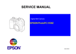
SERVICE MANUAL
Digital Still Camera
EPSON PhotoPC 2100Z
®
SEDC01002
Notice
All rights reserved. No part of this manual may be reproduced, stored in a retrieval system, or transmitted in any form or by any means electronic, mechanical,
photocopying, or otherwise, without the prior written permission of SEIKO EPSON CORPORATION.
All efforts have been made to ensure the accuracy of the contents of this manual. However, should any errors be detected, SEIKO EPSON would greatly
appreciate being informed of them.
The contents of this manual are subject to change without notice.
The above not withstanding SEIKO EPSON CORPORATION can assume no responsibility for any errors in this manual or the consequences thereof.
EPSON is a registered trademark of SEIKO EPSON CORPORATION.
General Notice:
Other product names used herein are for identification purpose only and may be trademarks or registered trademarks of their
respective owners. EPSON disclaims any and all rights in those marks.
Copyright © 2001 SEIKO EPSON CORPORATION.
Imaging & Information Product Division
TPCS Quality Assurance Department
PRECAUTIONS
Precautionary notations throughout the text are categorized relative to 1)Personal injury and 2) damage to equipment.
DANGER
Signals a precaution which, if ignored, could result in serious or fatal personal injury. Great caution should be exercised in performing procedures preceded by
DANGER Headings.
WARNING
Signals a precaution which, if ignored, could result in damage to equipment.
The precautionary measures itemized below should always be observed when performing repair/maintenance procedures.
DANGER
1.
ALWAYS DISCONNECT THE PRODUCT FROM THE POWER SOURCE AND PERIPHERAL DEVICES PERFORMING ANY MAINTENANCE OR REPAIR PROCEDURES.
2.
NO WORK SHOULD BE PERFORMED ON THE UNIT BY PERSONS UNFAMILIAR WITH BASIC SAFETY MEASURES AS DICTATED FOR ALL ELECTRONICS
TECHNICIANS IN THEIR LINE OF WORK.
3.
WHEN PERFORMING TESTING AS DICTATED WITHIN THIS MANUAL, DO NOT CONNECT THE UNIT TO A POWER SOURCE UNTIL INSTRUCTED TO DO SO. WHEN
THE POWER SUPPLY CABLE MUST BE CONNECTED, USE EXTREME CAUTION IN WORKING ON POWER SUPPLY AND OTHER ELECTRONIC COMPONENTS.
4.
WHEN DISASSEMBLING OR ASSEMBLING A PRODUCT, MAKE SURE TO WEAR GLOVES TO AVOID INJURIER FROM METAL PARTS WITH SHARP EDGES.
WARNING
1.
REPAIRS ON EPSON PRODUCT SHOULD BE PERFORMED ONLY BY AN EPSON CERTIFIED REPAIR TECHNICIAN.
2.
MAKE CERTAIN THAT THE SOURCE VOLTAGES IS THE SAME AS THE RATED VOLTAGE, LISTED ON THE SERIAL NUMBER/RATING PLATE. IF THE EPSON
PRODUCT HAS A PRIMARY AC RATING DIFFERENT FROM AVAILABLE POWER SOURCE, DO NOT CONNECT IT TO THE POWER SOURCE.
3.
ALWAYS VERIFY THAT THE EPSON PRODUCT HAS BEEN DISCONNECTED FROM THE POWER SOURCE BEFORE REMOVING OR REPLACING PRINTED CIRCUIT
BOARDS AND/OR INDIVIDUAL CHIPS.
4.
IN ORDER TO PROTECT SENSITIVE MICROPROCESSORS AND CIRCUITRY, USE STATIC DISCHARGE EQUIPMENT, SUCH AS ANTI-STATIC WRIST STRAPS, WHEN
ACCESSING INTERNAL COMPONENTS.
5.
DO NOT REPLACE IMPERFECTLY FUNCTIONING COMPONENTS WITH COMPONENTS WHICH ARE NOT MANUFACTURED BY EPSON. IF SECOND SOURCE IC OR
OTHER COMPONENTS WHICH HAVE NOT BEEN APPROVED ARE USED, THEY COULD CAUSE DAMAGE TO THE EPSON PRODUCT, OR COULD VOID THE
WARRANTY OFFERED BY EPSON.
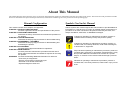
About This Manual
This manual describes basic functions, theory of electrical and mechanical operations, maintenance and repair procedures of the printer. The instructions and procedures included
herein are intended for the experienced repair technicians, and attention should be given to the precautions on the preceding page.
Manual Configuration
This manual consists of six chapters and Appendix.
CHAPTER 1. PRODUCT DESCRIPTIONS
Provides a general overview and specifications of the product.
CHAPTER 2. OPERATING PRINCIPLES
Describes the theory of electrical and mechanical operations of
the product.
CHAPTER 3. TROUBLESHOOTING
Describes the step-by-step procedures for the troubleshooting.
CHAPTER 4. DISASSEMBLY / ASSEMBLY
Describes the step-by-step procedures for disassembling and
assembling the product.
CHAPTER 5. ADJUSTMENT
Provides Epson-approved methods for adjustment.
CHAPTER 6. MAINTENANCE
Provides preventive maintenance procedures and the lists of
Epson-approved lubricants and adhesives required for servicing
the product.
APPENDIX Provides the following additional information for reference:
• Connector pin assignments
• Electric circuit boards components layout
• Electrical circuit boards schematics
• Exploded diagram & Parts List
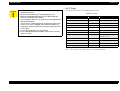
Symbols Used in this Manual
Various symbols are used throughout this manual either to provide additional
information on a specific topic or to warn of possible danger present during a
procedure or an action. Be aware of all symbols when they are used, and
always read NOTE, CAUTION, or WARNING messages.
A D J U S T M E N T
R E Q U IR E D
Indicates an operating or maintenance procedure, practice or
condition that is necessary to keep the product’s quality.
C A U T IO N
Indicates an operating or maintenance procedure, practice, or
condition that, if not strictly observed, could result in damage to,
or destruction of, equipment.
C H E C K
P O IN T
May indicate an operating or maintenance procedure, practice or
condition that is necessary to accomplish a task efficiently. It may
also provide additional information that is related to a specific
subject, or comment on the results achieved through a previous
action.
W A R N IN G
Indicates an operating or maintenance procedure, practice or
condition that, if not strictly observed, could result in injury or loss
of life.
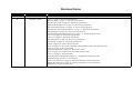
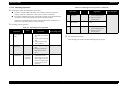
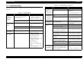
Revision Status
Revision
Date of Issue
A
October 15, 2001
B
November 12,2001
Description
First release
"Optics" on page -6: Revise the specification.
"Shooting Mode" on page -7 : Revise the specification.
"Shooting Operation" on page -10 : Revise the specification.
"Playback Mode Functions" on page -11 : Revise the specification.
"Beep Sound Specifications" on page -12 : Revise the specification.
"Miscellaneous (Abnormal Operation)" on page -15 : Revise the specification.
"LED Indications" on page -16 : Revise the specification.
"Lens Extending and Retracting Control" on page -19 : Revise the specification.
Table 1-14 on page 20 : Revise the specification.
Table 1-15 on page 21 : Revise the specification.
"Processing Time" on page -23 : Revise the specification.
"Accessories" on page -31 : Revise the specification.
"Option" on page -32 : Revise the specification.
"Tools" on page -48 : Revise the CAUTION and change Serial cable name and parts code.
Table 5-1 on page 60 : Revise the table.
"Adjustment Programs" on page -61: Revise the Caution.
"Tools" on page -61 : Change Serial cable name and parts code.
Table 5-3 on page 61: Revise the table.
"LCD (Brightness) Adjustment" on page -65 : Add the Serial cable parts code.
"USB ID Writing" on page -71 : Correct error.
"Front Cover Removal" on page -51: Delete the lubrication in the Check point.
"Battery Box Removal" on page -56 : Delete the lubrication in the Check point.
"Maintenance" : Delete the lubrication.
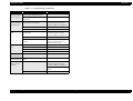
C
November 30,2001
"LCD (Brightness) Adjustment" on page -65 : Add the CAUTION and revise the adjustment procedure.
"USB ID Writing" on page -71 : Error correction.
D
February 20,2002
"Adjustment Programs" on page -61: Revise the CAUTION.
"Installation" on page -64 : Revise the procedure.
"BC (Battery Check) Compensation Value Writing" on page -64: Revise the CAUTION.
E
November 5,2002
Table 5-1 on page 60, Table 5-2 on page 61, Table 5-3 on page 61: White defect compensation is inclued in CCD Gain
Adjsutment.
"CCD Gain Adjustment, Shutter Compensation Black Defect Writing and White defect compensation" on page -67: White
defect compensation is inclued in CCD Gain Adjsutment.
Chapter 1 Product Description
1.1 Features ............................................................................................................... 4
1.2 Exterior View ...................................................................................................... 5
1.2.1 Dimensions and Weight ............................................................................... 5
1.3 Functional Specifications ................................................................................... 6
1.3.1 Image Data ................................................................................................... 6
1.3.2 Optics ........................................................................................................... 6
1.3.3 Shooting Mode ............................................................................................. 7
1.3.3.1 Shooting Functions .............................................................................. 7
1.3.3.2 Shooting Operation ............................................................................ 10
1.3.4 Playback Mode Functions .......................................................................... 11
1.3.5 Setup Mode Functions ............................................................................... 12
1.3.5.1 Beep Sound Specifications ................................................................ 12
1.3.6 Communication with PC ............................................................................ 13
1.3.7 Memory ...................................................................................................... 14
1.3.8 Built-in Clock ............................................................................................ 14
1.3.9 Detection of Battery Status ........................................................................ 14
1.3.10 Miscellaneous (Abnormal Operation) ..................................................... 15
1.3.11 Indication ................................................................................................. 15
1.3.11.1 Overview ......................................................................................... 15
1.3.11.2 LED Indications .............................................................................. 16
1.3.11.3 Shooting Status Display on Color LCD .......................................... 17
1.3.12 Switches and Buttons ............................................................................... 18
1.3.12.1 Switches and Buttons ...................................................................... 18
1.3.12.2 Locations of Switches and Buttons ................................................. 18
1.3.13 Lens Extending and Retracting Control .................................................. 19
1.3.14 Storage in the Camera .............................................................................. 20
1.3.14.1 Shooting ........................................................................................... 20
1.3.15 Playback / DPOF ..................................................................................... 21
1.3.15.1 SETUP ............................................................................................. 22
1.3.16 Processing Time ....................................................................................... 23
1.3.17 File Size and Number of Shots ................................................................ 23
1.3.17.1 File Size ........................................................................................... 23
1.3.17.2 Average Number of Shots with CompactFlash Memory Card
(Approximate Values) .................................................................................... 23
1.3.18 Sequential Numbering of Files ................................................................ 24
1.3.18.1 Folder Name and File Name ........................................................... 24
1.3.18.2 Fundamental Functions ................................................................... 24
1.3.18.3 Defining the Highest File Number in CF Card ............................... 24
1.3.18.4 Processing for Number 999 Folder ................................................. 24
1.3.18.5 Others .............................................................................................. 24
1.4 Interface Specifications ....................................................................................
1.4.1 USB Interface ............................................................................................
1.4.2 AC Adapter Input ......................................................................................
1.4.3 CompactFlash ............................................................................................
1.4.4 Exclusive Communication Cable ..............................................................
1.4.4.1 USB Cable .........................................................................................
1.4.5 Power Supply .............................................................................................
1.4.6 Battery Life ................................................................................................
1.4.7 Power Saving Specifications .....................................................................
1.4.7.1 Shooting Mode ..................................................................................
1.4.7.2 Playback Mode ..................................................................................
1.4.7.3 Communicate Mode ..........................................................................
1.4.7.4 SETUP Mode ....................................................................................
25
25
25
25
26
26
26
26
27
27
28
29
29
1.5 Accessories ........................................................................................................ 31
1.6 Option ................................................................................................................ 32
1.7 Environmental Conditions ...............................................................................
1.7.1 Operating Conditions / Storage Conditions ...............................................
1.7.2 Power Supply Specifications .....................................................................
1.7.3 Intended Location of Use ..........................................................................
33
33
33
33
1.8 Safety Standards & Reliability ........................................................................ 34
1.8.1 EMI and Safety Standards ......................................................................... 34
1.9 Prohibitions and Precautions .......................................................................... 35
Chapter 2 Operating Principles
2.1 Overview ............................................................................................................
2.1.1 Circuit ........................................................................................................
2.1.2 Operating Principles of Control Circuit .....................................................
2.1.3 Operating Principles of Power Supply Circuit ..........................................
2.1.3.1 Power Supply Voltages .....................................................................
2.1.3.2 Operating Principles of Power Supply Circuit ..................................
2.1.3.3 Power Supply Circuit on the Main Circuit Board .............................
2.1.3.4 Power Supply Circuit on Flash Circuit Board ...................................
2.1.4 Operating Principles of Flash Circuit ........................................................
2.1.5 Fuses ..........................................................................................................
37
37
39
40
40
42
42
42
42
42
Chapter 3 Troubleshooting
5.3.7 USB ID Writing ......................................................................................... 71
3.1 Troubleshooting ................................................................................................ 44
Chapter 6 Maintenance
Chapter 4 Disassembly and Assembly
6.1 Overview ............................................................................................................ 73
6.1.1 Check Items before Shipment .................................................................... 73
4.1 Overview ............................................................................................................
4.1.1 Precautions .................................................................................................
4.1.2 Tools ..........................................................................................................
4.1.3 Screws ........................................................................................................
47
47
48
49
4.2 Disassembly .......................................................................................................
4.2.1 Housing Disassembly ................................................................................
4.2.1.1 Rear Cover Removal .........................................................................
4.2.1.2 Front Cover Removal ........................................................................
4.2.1.3 Front Cover Disassembly ..................................................................
4.2.2 Disassembly of Circuit Boards ..................................................................
4.2.2.1 Release Circuit Board Removal ........................................................
4.2.2.2 Power Supply Circuit Board Removal ..............................................
4.2.2.3 Monitor LCD Removal .....................................................................
4.2.2.4 Flash Circuit Board Removal ............................................................
4.2.2.5 Battery Box Removal ........................................................................
4.2.2.6 Lens Assy (Lens & CCD Unit) Removal ..........................................
49
50
50
51
52
52
52
53
53
54
56
57
Chapter 5 Adjustment
5.1 Overview ............................................................................................................ 60
5.2 Tools ...................................................................................................................
5.2.1 Tools ..........................................................................................................
5.2.2 Adjustment Programs ................................................................................
5.2.3 Explanation of Error Codes .......................................................................
61
61
61
62
5.3 Adjustment ........................................................................................................
5.3.1 Installation of firmware .............................................................................
5.3.1.1 Version Confirmation ........................................................................
5.3.1.2 Installation .........................................................................................
5.3.2 BC (Battery Check) Compensation Value Writing ...................................
5.3.3 LCD (Brightness) Adjustment ...................................................................
5.3.4 CCD Gain Adjustment, Shutter Compensation
Black Defect Writing and White defect compensation .....................................
5.3.5 Strobo Adjustment .....................................................................................
5.3.6 AF (Auto Focus) Compensation ................................................................
63
63
63
64
64
65
67
68
69
Chapter 7 Appendix
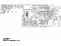
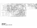
7.1 Circuit Board Connection Diagram ............................................................... 75
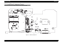
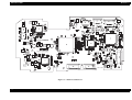
7.2 Circuit Board Component Layout .................................................................. 77
7.3 Circuit Diagrams .............................................................................................. 83
7.4 Exploded Diagrams .......................................................................................... 95
7.4.1 ASP List ................................................................................................... 100
7.5 AF Adjustment Chart .................................................................................... 101
1
CHAPTER
PRODUCT DESCRIPTION
PhotoPC 2100Z
Revision B
1.1 Features
Major features of EPSON PhotoPC 2100Z are as follows:
Advanced appearance
Teardrop shaped design, which is easy to hold and carry
Digital camera design of the 21st century (quite different from competitors')
High quality image
CCD with 2,300,000 pixels
Image processing technology using the DSP (Digital Signal Processor) for
User interfaces
Shooting is possible immediately after opening the lens barrier.
Function display is more easy to understand, thanks to use of icon animation.
Access FDA format (Function Direct Assign) as GUI operations, which has a
high evaluation of user-friendliness.
External interfaces
USB (Mass Storage Class)
AC adapter input (DC7.0V, 2.0A)
exclusive use with digital cameras
High quality image created by Hypict loaded with a color noise removal
function
Compatible with EPSON color space
Compatible with PIM (PRINT Image Matching)
A variety of useful functions
Lens barrier coupled collapsible optical 2 times zoom lens, zoom interlocking
optical viewfinder
Built-in flash (automatic, red-eye reduction, prohibition)
EPSON 1.6 type D-TFD color LCD monitor
8MB CompactFlash Card is attached as standard
USB and AC adapter terminals
Print (DPOF: Digital Print Order Format) button
Conforming to industry standards
DCF (Design rule for Camera File system) format
DPOF file creation function is supported.
Software
EPSON Photo4!
EPSON PhotoQuicker
Photo Suite 3SE (Win)
Photo Suite 3 (Mac)
Photo Vista Full Version (Win/Mac)
Product Description
Features
4
PhotoPC 2100Z
Revision B
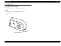
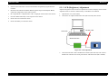
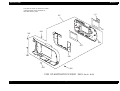
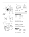
1.2 Exterior View
1.2.1 Dimensions and Weight
Dimensions
130 mm × 73 mm × 46.7 mm
(not including some protrusions)
Weight
265 g (without any of the batteries, strap and memory card)
Tripod mount
Compliant with JIS B7103 1/4
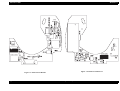
Appearance
Figure 1-1. Exterior View
Product Description
Exterior View
5
PhotoPC 2100Z
Revision B
1.3.2 Optics
1.3 Functional Specifications
CCD
1/2.6 inch color area CCD, interlace reading, complementary color filter
Total pixels:
2,300,000 pixels (1901 x 1212)
Effective pixels:
2,180,000 pixels (1806 x 1206)
1.3.1 Image Data
Recording format
JPEG compression: DCF (Exif 2.1) format
Lens
Collapsible 2 times zoom lens
f = 5.6-11.2 mm (equivalent to 35-70 mm on a 35 mm film camera)
Brightness F3.3 (W)-F4.6 (T), 6 elements in 5 groups construction (2
Thumbnail image
160 × 120 pixels
Image size
Hypict:
2160 × 1440 pixels
Print:
180 × 1200 pixels
e-mail:
720 × 480 pixels
spherical lens elements)
Aperture
F3.3 / 6.2 (Wide) - F4.6 / 8.6 (Telescopic)
Viewfinder
Real image motor type (field of view ratio 85% at eye-point)
With AF target mark
Color
Full color (24-bit full color)
PIM (PRINT Image Matching)
The PIM commands are stored in the Exif header's information area of Maker
Note tag (0x927C). The commands are as follows:
Focus
Auto focus
Bright setting (user setting) / AutoPhotoFine mode setting* (Maker setting)
Shooting range
0.3 m to 0.5 m (macro mode: telescopic end fixed)
0.5 m to infinity (normal)
*: Modes available are normal mode, macro mode and night scene mode.
Shutter
Electromagnetic release mechanical shutter and electric iris
Normal (flash OFF):
1/2, 1/8 - 1/1000 second
Flash ON (Wide):
1/30 - 1/1000 second
Flash ON (Tele):
1/60 - 1/1000 second
Product Description
Functional Specifications
6
PhotoPC 2100Z
Revision B
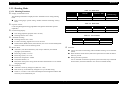
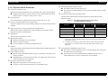
1.3.3 Shooting Mode
Table 1-1. Flash Auto
1.3.3.1 Shooting Functions
ISO110
ISO110 ~ 200
ISO140
(Flash Firing)
Wide
LV8.3 or above
-
LV8.3 or below
Tele
LV10.3 or above
LV10.3 ~ 9.4
LV9.4 or below
Display of information zone
The following information is displayed in the “information zone” during shooting
mode.
Date / zoom gauge / special setting / number of frames remaining / battery
status
Table 1-2. Flash OFF
Exposure control
Center-weighted light metering programmed AE (aperture and shutter speed are
adjustable)
LCD shooting display
TTL image playback (playback rate 1/20 sec.)
Shooting field of view is 98%.
ISO120
ISO120 ~ 200
ISO200
Wide
LV8.3 or above
LV8.3 ~ 7.4
LV8.4 or below
Tele
LV10.3 or above
LV10.3 ~ 9.4
LV9.4 or below
Table 1-3. Forced Flash
Viewfinder shooting
Shooting field of view is 85%.
For macro shooting, digital zoom can not be used.
Shutter button, MENU button, Zoom button, Lens Cover switch and Playback
ISO120
ISO140
Wide
LV8.3 or above
LV8.e or below
Tele
LV10.3 or above
LV10.3 or below
button are valid as in LCD shooting mode.
Built-in flash
Automatic (TTL direct flash auto), off, red-eye reduction, forced flash
(daylight synchronization)
Flash range (wide): 0.5-3.2 m
Flash range (Tele): 0.5-2.3 m
Flash color temperature: 5700K
GN (Guide Number): 9
Restoration from power saving mode entered in flash off state occurs without
charging the flash.
Self-timer
Can be used with LCD shooting and Viewfinder shooting. 10-second timer
(fixed).
With self-timer mode selected, self-timer operation starts when the shutter
button is pressed.
During self-timer operation:
User is informed of self-timer operation by the front LED, beep sound and
LCD monitor (self-timer animation: not used in viewfinder mode).
ISO sensitivity
Automatic sensitivity changeover (ISO 100 ~ 200)
ISO sensitivity is automatically changed over by Auto ISO setting.
Table 1-1 to Table 1-3 show the relationship between brightness and the ISO
sensitivity to be automatically set.
Product Description
Functional Specifications
7
PhotoPC 2100Z
Revision B
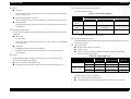
Macro
AF range
Switching of resolution (Print/e-mail)
The default setting is “Print”.
The AF range for macro shooting is 30 cm to 50 cm, with optical zoom fixed
to the telescopic end.
Table 1-4. Resolution Switching
Status
When the zoom button is pressed:
Macro + digital zoom is can be used. Macro + optical zoom can not be used.
In macro mode:
Viewfinder shooting is disabled. (Viewfinder shooting can not be selected by
menu button.)
Backlight compensation
Used in both LCD shooting and viewfinder shooting. The following operation will be
performed:
Flash OFF:
Operation
Print (Normal)
Hypict
e-mail
Switching to
Hypict
To Hypict
-
To Hypict
Switching to email
To e-mail
Switching impossible
(Gray out)
-
Switching to
Print
-
To Print or e-mail *
To Print
Note: *: Resolution changes to that for e-mail if the previous setting was e-mail. If it was not
e-mail, resolution changes to that for Print.
Sequential numbering of files
+1.5EV offset
Shutter speed: It is possible for exposure can +1.5EV. When it is dark around
even 1/8 second.
Flash ON:
Daylight synchronization (by Forced flash)
Daylight synchronization is replaced with slow synchronization when it
becomes dark.
Hypict
The highest EPSON folder number and file number in the DCIM Folder in the CF card
are stored in memory.
Hyper night scene
Shutter speed: fixed to 1/2 second
Aperture: open
Can be used for LCD shooting and viewfinder shooting. The following
processing will be performed:
Table 1-5. Hyper Night Scene
Characterized by a higher boundary detection accuracy, a larger filter size and
improved noise suppression capability.
Can be used only while Hypict is set.
Switching of image quality (Print/e-mail) is disabled while Hypict is set.
Hyper night scene
Hyper night
scene + Hypict
Pixel
compensate
Slow
synchronization
Noise
reduction
Flash Auto
-
Available
Available
Flash OFF
-
Not available
Available
Flash Auto
Available
Available
Available
Flash OFF
Available
Not available
Available
White balance
The following two modes are supported:
TTL system automatic white balance
AUTO mode/Fixed mode (color temperature is 5100K) can be selected
Product Description
Functional Specifications
8
PhotoPC 2100Z
Revision B
Digital zoom
Smooth digital zoom for a maximum of 2.5 magnification can be used.
9-stage switching
Processing is slow during digital zoom operation.
Shift to VRF shooting mode during digital zoom on, digital zoom function is
removed.
The image is stored with an image size determined by the selected recording mode.
e-mail:
Print:
Hypict:
720 × 480
1800 × 1200
2160 × 1440
Optical zoom
Wide end (35mm) - telescopic end (70mm), 6-step changeover. (Coupled with
viewfinder)
Shooting menu display/non-display
Switching between shooting menu display and non-display and selection of viewfinder
shooting (LCD off) are possible.
Simple DPOF
DPOF number of prints can be set. (This information can be used when
images are to be viewed after shooting.)
If the DPOF file is write-protected or broken, the Simple DPOF function does
not permit setting or recording.
Simultaneous setting for Hyper night scene and backlight compensation
The following processing will be performed:
Flash ON: Slow synchronization
Flash OFF: In the same way as for Hyper night scene, shutter speed is fixed to
1/2 second and aperture is opened.
Product Description
Functional Specifications
9
PhotoPC 2100Z
Revision B
1.3.3.2 Shooting Operation
Table 1-6. Shooting Process Operation (continued)
Pressing the shutter button halfway (focus lock)
Evaluates AF/AE/AWB, and reflects the evaluated value in the preview
display. If the CF is pulled out in this status, an alarm is indicated.
Even if the communication cable is inserted, transition to the communication
mode does not take place during half-press of the shutter button.
Transition to communication mode is achieved either after cancellation of
half-press of the shutter button or after shooting.
User/Camera
Operation
LCD
Contents of Camera
Operation
Target
Processing Time
Pressing the
OK button
ON
Starting to display motion
-
4-2
Pressing the
DPOF button
ON
Displaying the simple DPOF
screen.
4-3
Next shooting
ON
Starting to display motion
4-1
Shooting process operation
Table 1-6. Shooting Process Operation
User/Camera
Operation
1
2
3
Pressing the
shutter button
fully
Image
processing
Image
confirmation
Product Description
LCD
OFF
Contents of Camera
Operation
Shooting based on the
Processing the image
picture (through image).
Target
Processing Time
Transition to each
shooting mode.
-
AE, AWB, AF evaluation
data.
Capturing the CCD image
data.
Transferring the image
data to SDRAM.
OFF
picture (through image).
Transition to each
shooting mode.
Processing after shooting
After shooting, AE will be executed at the beginning of preview.
2 seconds
data.
Starting to charge the
flash when it is to be
used.
ON
(including
viewfinder
shooting)
Displaying the image
-
confirmation screen
during image processing.
After image processing,
the camera transfers the
image to the CF (back
operation).
Functional Specifications
10
PhotoPC 2100Z
Revision B
1.3.4 Playback Mode Functions
Display in information zone
Displays the following information in the “information zone” while in playback mode.
Displayed frame number / DPOF number of prints / PIM setting/ total DPOF
number of prints / resolution / battery status / cursor
Resetting the DPOF number of prints
The DPOF number of prints can be reset.
This function is disabled (display turns gray) when no DPOF number of prints
has been set.
Playback of images taken with other models
The table below indicates the processing (operation) for images taken by other
EPSON's cameras.
Image playback
95% framing display is performed, but only with an aspect ratio of 3:2 only.
Table 1-7. Processing (Operation) for Images Taken
by Other EPSON's Cameras
One-by-one image playback (forward/backward)
Function
PhotoPC 800
PhotoPC 850Z
PhotoPC 3000Z
PhotoPC 3100Z
Image file playback (DCF)
Available
Available
Available
Not available
Not available
Available *1
User PIM
-
-
Not available *2
TIFF image playback
-
Thumbnail display
Thumbnail display
Motion picture playback
-
Not available
Not available
Images are displayed one by one by switching. Images are scrolled by means of the W/
T button.
High-speed one-by-one image playback (forward/backward)
When the W/T button is held pressed at a 9-division display, the camera performs
high-speed one-by-one image playback.
Split display
DPOF
The LCD shows nine images at a time.
Note: *1: The DPOF number of prints for any camera other than PhotoPC 2100Z must be
cleared before setting the DPOP number of prints (including simple DPOF setting)
with PhotoPC 2100Z.
Magnification display
Magnifies the image twice on the display.
Smooth scrolling is possible.
The zoom display icon indicates the magnified area.
*2: User PIM is not available for images taken with any camera other than PhotoPC
2100Z. However, User PIM of the cameras other than PhotoPC 2100Z can be
maintained.
Deletion
Single image deletion and all images deletion (including deletion of DPOF setting and
PIM setting) are possible.
DPOF (number of prints)
Permits setting of the DPOF number of prints. A maximum of 9 prints for one
image are allowed.
If the DPOF file is write-protected or broken, a new DPOF file will be created
and the old DPOF file will be deleted.
Writing DPOF and PIM data in the CF card
The camera writes the PIM data in the CF card immediately after setting and
the DPOF data at mode switching.
If the batteries are removed during DPOF and PIM setting, the camera
perform PIM writing in the CF card but dose not write PDOF.
Brightness compensation (User PIM)
Brightness compensation: Can be turned on or off.
Turning on or off is permitted irrespective of the DPOF setting.
Product Description
Functional Specifications
11
PhotoPC 2100Z
Revision B
1.3.5 Setup Mode Functions
1.3.5.1 Beep Sound Specifications
Display of information zone
The following three types of sounds are used:
A: 4.9KHz
B: 1.2KHz
C: 2.4KHz
Displays the following information in the “information zone” while in setup mode.
Date / cursor / battery status
Date and time setting
Table 1-8. Beep Sound Specifications
Setting of year, month and day, and hour and minute is available.
Date display switching
The date display method can be changed.
The setting is kept in memory even if the backup battery has run down.
The setting is stored in the 8MB flash ROM.
The date display method can be selected among the following three patterns:
Sound
Item Pattern
Name
Mode
Status
Sound Patterns
1
SM
Shooting
Changes from off to shooting
mode (excluding communication
mode)
BCBCA
2
SM2
Playback
Changes from off to playback
mode (excluding communication
mode)
BCBCA
3
PF
Lens cover
close
Changes from shooting mode to
off: No sound is used when the
lens cover is closed in playback
mode.
CABC
4
PF2
Turning off with
playback button
Changes from playback mode to
off
CABC
5
MC
PlaybackShooting
Switching sound between
playback and shooting mode
BBCA
6
BO
Shooting/
Playback
Tool box open
BCC
7
BC
Shooting/
Playback
Tool box closed
CBB
8
HC
Shooting/
Playback
Highlight moved in tool box
Setting of beep sounds (operation sounds and shooting sounds) is available in the
following three ways:
9
FI
Shooting/
Playback
Function setting (icon moves to
left)
Both shooting sounds and operation sounds are used.
Only shooting sounds (including self-timer sounds) are used.
Neither shooting sounds nor operation sounds are used.
10
FB
Shooting/
Playback
Function cancellation (icon
moves to right)
11
FF
Shooting
To lower hierarchy
CB
12
SC
Shooting
To higher hierarchy
CB
13
TP
Shooting
Shutter button
M: Month, D: Day, Y: Year
Card format
CF cards can be formatted.
CF card formatting operation is not performed when no CF card has been
inserted.
Beep sound setting
Product Description
Functional Specifications
B
BC
A
12
PhotoPC 2100Z
Revision B
1.3.6 Communication with PC
Table 1-8. Beep Sound Specifications (continued)
Sound
Item Pattern
Name
Mode
Status
Sound Patterns
14
ST
Shooting
Self-timer button
AC (repeats until
shutter starts
operating)
16
IC
Playback
High-speed switching
B
17
MO
Shooting/
Playback
Menu on/off
B
18
SD
Battery life
expired
Batteries have run down.
AAC
19
P4
Communication
Transition to communication
CBB
20
CF
Power on all
No CF card
AAC
21
CD
Power on all
Transition to power saving mode
22
DP
Playback
DPOF button is pressed
23
DPR
Playback
The DPOF number of prints is
reset
CBB
BC, off and C
CB
Note: *1: The sound ST is not given forth in complete synchronization with the self-timer
LED.
*2: The sound BS is in synchronization with changeover of image.
*3: During playback of a first sound, if a second sound occurs (interrupts), the second
sound overrides the first sound.
Product Description
Type of communication
Only USB communication (Mass Storage Class) is available.
Serial communication is not supported.
Start of communication
When the communication cable (USB) is inserted in shooting, playback or
setup mode, the camera enters the communication mode.
Even when the communication cable (USB) is inserted in shooting, playback
or setup mode, the camera does not enter the communication mode if a CF
card has not been inserted.
Communication is started by pressing the playback button when the cable has
been inserted.
Communication is started when the lens cover is opened if the cable has been
inserted.
LED indication during communication
Orange at 1Hz when there is no communication data access
Green at 2Hz when there is communication data access
End of communication
When the playback button is pressed during communication, the communication mode
is ended and the power turns off.
Communication command
The specifications related to the USB Mass Storage Class are based on the “USB Mass
Storage Class UFI Command Specification Rev.1.0”.
Functional Specifications
13
PhotoPC 2100Z
Revision B
1.3.7 Memory
1.3.8 Built-in Clock
Built-in RAM
Built-in clock
The camera incorporates a clock.
Default is January 1, 2001, 0:00. Does not count down earlier than this time.
Capable of counting up to December 31, 2035, 23:59. Does not count up later
8MB (64Mb (32 bits × 2M))
Built-in ROM
1MB (for program only)
Image memory
CompactFlash Memory Card Type 1 is used.
A maximum of 256MB of CF card can be accessed.
PC-DOS format: 512B/Sector
16bitFAT (16MB or more)
than this time.
Even while replacing the batteries, the internal lithium secondary battery
maintains the date and time setting.
1.3.9 Detection of Battery Status
Battery status
Battery status can be detected in the following steps:
Batteries full / Batteries half / Exchange batteries / Battery ran down.
Product Description
Functional Specifications
14
PhotoPC 2100Z
Revision B
1.3.10 Miscellaneous (Abnormal Operation)
1.3.11 Indication
When batteries are removed during operation:
1.3.11.1 Overview
When the batteries (or AC adapter) are removed during operation and re-inserted
Playback mode is set by pressing the playback button irrespective of the
previous operation.
Shooting mode is set when the lens cover is opened irrespective of the
previous operation.
If CF memory card is pulled out while power is on
The camera turns off automatically.
If CF memory card is inserted while power is on
The camera turns off automatically.
LCD monitor
EPSON 1.6 type D-TFD color LCD monitor
55,000 pixels: 237 x 234 pixels
Field of view ratio for shooting is 98%
At playback, each recorded image is displayed in 100% of recorded pixels.
(Aspect ratio 3:2 only)
Operation sound / shutter sound
All sounds (Joy), Only shooting sound (including self timer sound) (Only shoot), or No
sound (Silent) can be selected.
Self timer indication (Front LED)
Front red LED indication
Slow-speed flashing (8 seconds), High-speed flashing (the last 2 seconds)
LCD indication
Self-timer animation is displayed during operation of the self-timer. (Beep,
LED and animation may not be synchronous.)
There is no LCD indication at viewfinder shooting (LCD is off).
Viewfinder side LED
3-mode display of green light on / flashing / out.
3-mode display of red light on / flashing / out.
3-mode display of orange light on / flashing / out.
Product Description
Functional Specifications
15
PhotoPC 2100Z
Revision B
1.3.11.2 LED Indications
*2: Duty flashing has off time longer than on time. 0.5Hz: on for 0.1 second and off for
1.9 second.
Table 1-9. LED Indications
Camera
Status
Error status
Detailed Status
LED
Green
Orange
Error status
On
CF full to its capacity
(No CF inserted)
Waiting
Red
(1Hz)
Battery life expired
(playback mode)
(1Hz)
Power is just turned on
(Busy)
(2Hz)
Mode switching (Busy)
(2Hz)
Image processing (Busy)
(2Hz)
Focusing time
(2Hz)
Flash charging
(2Hz)
(2Hz)
Reading from CF
(2Hz)
Communicated with PC
(2Hz)
Operation OK
Operation is OK (both
shooting and playback)
Self-timer
shooting
Self-timer is used
1
2
3
4
5
If batteries have run down when
CF is full to its capacity (no CF is
inserted)
Shooting: Red 1Hz
Playback: Red 1Hz
If mode is switched when CF is
full to its capacity (no CF is
inserted)
From playback to shooting: Red 2Hz
If communication is started when
CF is full to its capacity (no CF is
inserted)
Shooting: Orange 1Hz (Red 2Hz when CF is
From shooting to playback: Red 2Hz (Only
when CF is not inserted))
not inserted)
Playback: Orange 1Hz (Red 2Hz when CF is
If the camera enters power saving
mode 1 when CF full to its
capacity (no CF is inserted)
Shooting: Orange on
If the camera enters power saving
mode 2 when CF is full to its
capacity (no CF is inserted)
Shooting: Orange Duty flashing (Only
viewfinder mode)
Playback: Orange on
Note: *: In playback mode, Red LED flashes at 2Hz only when no CF is inserted.
LED INDICATIONS FOR BATTERY LIFE EXPIRATION
(1Hz)
Table 1-11. LED Indications for Battery Life Expiration
On
1
(1Hz/
2Hz)
*1
Power saving
Table 1-10. LED Indications for CF Full to its Capacity
(CF Not Inserted)
not inserted)
Data transfer to CF
Connected to PC
LED INDICATIONS FOR CF FULL TO ITS CAPACITY (NO CF INSERTED)
CF R/W error
(2Hz) In playback
mode, this
indication occurs
only when no CF
is inserted
Battery life expiration
(Shooting mode)
Communication
Remarks
Power saving mode 1
On
Power saving mode 2
Duty
flashing *2
If batteries have run down (red 2Hz)
during mode switching (green 2Hz)
From shooting to playback: Red 1Hz
From playback to shooting: Red 1Hz
2
If batteries have run down (red 1Hz)
during communication (orange 1Hz)
Red 1Hz
3
If batteries have run down (red 1Hz)
in power saving mode (orange 1Hz)
Red 1Hz
Note: *1: Self-timer start to self-timer end: 10 seconds
Self-timer start to 8 seconds: 1Hz
8 seconds to self-timer end: 2Hz
Product Description
Functional Specifications
16
PhotoPC 2100Z
Revision B
1.3.11.3 Shooting Status Display on Color LCD
LED INDICATION FOR ERROR STATUS
In an error status, the red LED is lit and beep sound A (4.9KHz) is emitted for three
seconds and then power turns off automatically.
The color LCD monitor displays color frames for different functions. This function is
available only for LCD shooting.
Table 1-12. Shooting Status Display on Color LCD
LCD
Frame Color
Status
No display
Normal
Green frame
Macro
Yellow frame
Digital zoom
Note: Priority order: digital zoom frame > macro frame.
Product Description
Functional Specifications
17
PhotoPC 2100Z
Revision B
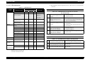
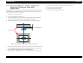
1.3.12 Switches and Buttons
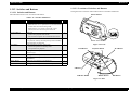
1.3.12.2 Locations of Switches and Buttons
The figures below show the names and locations of switches and buttons.
1.3.12.1 Switches and Buttons
The table below shows a list of switches and buttons.
Shutter Button
Table 1-13. Switches and Buttons
Switch/Button
Functions
Qty
Lens Cover Switch
Manual slide type
• When the lens cover is opened, the lens extends and the
camera enters the LCD shooting mode.
• When the lens cover switch is slid to the “Close”
position, the lens retracts and power turns off.
1
Playback Button
Push type
• Used to turn playback mode on/off.
• Also used to turn power off in communication mode.
1
Shutter Button
Push type
Two positions, namely, the half-pressed position and fullypressed position, are detected.
1
W/T Button
Right-and-left two-position seesaw type
• Lens zoom operation in shooting mode
• GUI operation for playback
1
F Button
Push type. For GUI operation (exclusive use for Function
Direct Assign)
1
SCROLL Button
Push type. For GUI operation (for menu selection)
1
OK Button
Push type. For GUI operation (for menu setting/
cancellation)
1
MENU Button
Push type. For switching LCD indications.
1
Print Button
Push type. For setting the DPOF number of prints.
1
Lens Cover Switch
Figure 1-2. Front
Print Button
Playback Button
W/T Button
F Button
SCROLL Button
MENU Button
OK Button
Figure 1-3. Rear
Product Description
Functional Specifications
18
PhotoPC 2100Z
Revision B
1.3.13 Lens Extending and Retracting Control
Lens extending and retracting are controlled by the opening/closing operation of the
lens cover.
Setting the Lens Cover Switch to “Open” position:
Opens the lens cover and extends the lens.
Setting the Lens Cover Switch to “Close” position:
Retracts the lens and closes the lens cover.
Lens cover opening/closing switch operation is ignored during communication.
If the batteries are running down when the lens is in the extended position, the lens
is retracted first and then power is turned off.
After completion of lens retracting
During a period of 3 second, lens cover OPEN operation can not be detected.
Product Description
Functional Specifications
19
PhotoPC 2100Z
Revision B
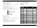
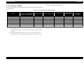
{: Stored, ×: Default, ∆: Conditional
1.3.14 Storage in the Camera
1.3.14.1 Shooting
The table below indicates the conditions under which the camera stores the parameters
in shooting mode.
Table 1-14. Storage System in Shooting Mode
Mode Switching
Playback Button
ON/OFF
(Without
communication)
Item
Viewfinder ↔
LCD
Menu ON/OFF
Power Saving
Mode 1 *1
Power Saving
Mode 2 *1
After Shooting
Lens Cover
Closed
Power OFF
After
Communication
with PC
Self-timer
×
{
×
×
×
×
×
Macro/digital zoom position
{
∆ *2
∆ *2
∆ *2
{
×
×
Backlight compensation
{
{
{
{
{
×
×
Resolution switching between
Hypict, Print and e-mail
{
{
{
{
{
{
×
Hyper night scene
{
{
{
{
{
×
×
White balance
{
{
{
{
{
×
×
Flash setting
{
{
{
{
{
×
×
Optical zoom position
{
{
{
×
{
×
×
{
{
{
{
{
{
{
Sequential numbering of files
*5
Note: *1: Power saving mode 1: 8-bit sub CPU ON, LED indication, same status as viewfinder
mode.
Power saving mode 2: The orange LED flashes (Duty is changed).
*2: Stored in LCD mode. Neither macro shooting nor digital zoom function is available
in viewfinder mode.
*3: During function setting (when the tool box is open), only the setting is stored in the
status above and the tool box is closed.
*4: No alarm is stored.
*5: Stored in the 8-bit sub CPU.
*6: All the settings return to default status when the lithium battery (backup battery) runs
down.
Product Description
Functional Specifications
20
PhotoPC 2100Z
Revision B
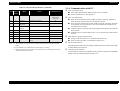
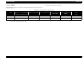
{: Stored, ×: Default, ∆: Conditional
1.3.15 Playback / DPOF
The table below indicates the conditions under which the camera stores the parameters
in playback mode.
Table 1-15. Storage System in Playback Mode
Mode Switching
Lens Cover / Playback Button
(Without communication)
Menu ON/OFF
Power Saving Mode 1
Power Saving Mode
2 *1
Playback Button
Power OFF
After
Communication
with PC
Alert display
×
-
{
×
×
×
Magnified image display
×
-
{
×
×
×
Tool box is open
×
-
{
×
×
×
Item
9-division display mode
Displayed image number
×
{
*3
{
{
{
×
×
{
{
{
×
×
DPOF information
{
{
{
{
{
*2
{
PIM information
{
{
{
{
{
*2
{
Note: *1: The orange LED flashes (Duty is changed).
*2: Stored in the CF card.
*3: The displayed frame number is reset (to the newest number) at shooting by mode
switching.
*4: When the lithium battery (backup battery) runs down, all the settings return to
default status, except for the DPOF setting and PIM setting stored in the CF card.
Product Description
Functional Specifications
21
PhotoPC 2100Z
Revision B
{: Stored, ×: Default ∆: Conditional
1.3.15.1 SETUP
The table below indicates the conditions under which the camera stores the parameters
in SETUP mode.
Table 1-16. Storage System in SETUP Mode
Item
Mode Switching
Power Saving Mode 2
Lens Cover / Playback Button Power Saving Mode 1
*1
(Without communication)
Lens Cover Closed
Power OFF
After Communication
with PC
Date and time
{
{
{
{
{
Date indication
{
{
{
{
{
Beep setting
{
{
{
{
{
Backup Battery Runs
Down
(Reset)
×
{
*2
×
Note: *1: The orange LED flashes (Duty is changed).
*2: Stored in the 8Mb flash ROM for program.
Product Description
Functional Specifications
22
PhotoPC 2100Z
Revision B
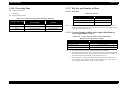
1.3.16 Processing Time
1.3.17 File Size and Number of Shots
Target start-up time:
1.3.17.1 File Size
3.8 seconds
Table 1-18. File Size
Target processing time
Image Quality Setting
Table 1-17. Target Processing Time (Shooting / Playback)
Image Quality Setting
Minimum time to enable the
next shooting
Processing Time for
Playback
e-mail
About 5 seconds
About 3 seconds
Print
About 7 seconds
About 9 seconds
Hypict
About 12 seconds
About 10 seconds
Target File Size
e-mail (720 × 480)
About 70KB
Print (1800 × 1200)
About 500KB
Hypict (2160 × 1440)
About 700KB
Note: *1: The image file size varies with the subject, since image data is compressed and
recorded in JPEG format. The sizes indicated above represent approximate average
values, given for information only.
1.3.17.2 Average Number of Shots with CompactFlash Memory
Card (Approximate Values)
Table 1-19. Average Number of Shots with CompactFlash
Memory Card (Approximate Values)
Image Quality Setting
8 MB
e-mail (720 × 480)
About 115 images
Print (1800 × 1200)
About 14 images
Hypict (2160 × 1440)
About 10 images
Note: *1: The number of shots is based on EPSON's measurement conditions.
*2: Each number indicated above is the average number of shots when no data has been
stored in the memory. If other files have been stored in the memory, the number of
shots permitted decreases depending on the remaining capacity.
*3: Since image data is compressed and recorded in JPEG format, the image file size
varies with the subject, thus the number of shots permitted varies. (There may be a
case where the average number of shots can not be taken.)
Product Description
Functional Specifications
23
PhotoPC 2100Z
Revision B
1.3.18 Sequential Numbering of Files
1.3.18.4 Processing for Number 999 Folder
When the 999EPSON folder stores images, the camera is disabled from shooting
1.3.18.1 Folder Name and File Name
(the camera displays the “CF card full to its capacity” status) if the CF card runs
out of free space. Then the sequential number is reset to 100EPSON-EPSN0001.
At this point, EPSON folders without any image files are deleted.
Folder name
∆∆∆EPSON
Also when EPSN9999.jpg is stored in the 999EPSON folder, the camera is
∆∆∆: Any of the numbers in the range of 100-999
The default is 100EPSON.
disabled from shooting (the camera displays the “CF card full to its capacity”
status). Then, the sequential number is reset to 100EPSON-EPSN0001. At this
point, EPSON folders without any image files are deleted.
File name
EPSN
.jpg
Even after the camera is disabled from shooting, changing the resolution may
enable the camera to shoot again.
: Any of the numbers in the range of 0001-9999
The default is EPSN0001.jpg.
Even after the camera is disabled from shooting, the camera is enabled to shoot
again if there is no EPSN9999.jpg file in the 999EPSON folder and a sufficient
free area is restored in the CF card by deleting image files.
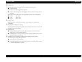
1.3.18.2 Fundamental Functions
The camera stores in its memory both the image folder numbers and the image file
numbers as serial numbers.
Every time the camera takes a picture, the highest file number in the CF card is
assigned to the picture to ensure the sequence in which the pictures taken are
played back. The highest file number in the CF card is compared with the latest
serial number stored in memory. Then, the higher one is assigned to the picture
taken.
1.3.18.5 Others
Once the “delete all” function is used in playback mode (locked images are not
deleted), all EPSON folders with no files are also deleted.
Sequential numbering is kept even after the CF card is formatted.
Sequential numbering reset function is not provided.
1.3.18.3 Defining the Highest File Number in CF Card
If the folder of the highest number in the card is an EPSON folder, the highest file
number in that holder is defined as the highest file number in the memory card.
If the folder of the highest number in the CF card is not an EPSON folder (ex.
“100CANON”), a new EPSON folder is created and given a number one higher
than the existing highest folder number. When a new picture is taken, an image file
with the number 0001.jpg is created as the highest file number in the CF card.
Product Description
Functional Specifications
24
PhotoPC 2100Z
Revision B
1.4.2 AC Adapter Input
1.4 Interface Specifications
Polarity: Center-plus
USB connector
For exclusive use with the AC adapter EU-40 (7.0V 2A)
The exclusive USB cable must be used.
AC adapter input
1.4.3 CompactFlash
DC input terminal for AC adapter (7.0V) EIAJ RC-5320 type 3 (compatible with EU40)
CompactFlash
CompactFlash interface
CompactFlash Card Type1 is supported.
A capacity of 256MB is available.
CompactFlash card interface
CompactFlash Card Type1 is supported.
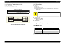
1.4.1 USB Interface
Compatible with USB Ver1.1
12Mbps high-speed transmission
Communication speed:
More than 150 kilobytes/s (varies with PC, however)
Cable:
Mini DIN-Type A connector
Table 1-20. USB Connector Pin Assignment
Pin No.
Signal
I/O
1
VDD
I
8
D-
I/O
Remarks
Power
Data signal
6
D+
I/O
4
GND
-
GND
Data signal
SHELL
SHELL
-
SHELL
Note: *1: USB operation is guaranteed even through 5-step connection of hubs.
*2: The USB interface must not be used for any communication other than between a PC
and the camera.
Product Description
Interface Specifications
25
PhotoPC 2100Z
Revision B
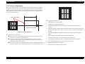
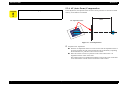
1.4.4 Exclusive Communication Cable
1.4.4.1 USB Cable
For exclusive use with PhotoPC 2100Z
Table 1-21. USB Cable
Length
1.4.5 Power Supply
Batteries
Size AA
Four batteries are used
Ni-MH rechargeable battery / Ni-cd rechargeable battery / alkali battery /
lithium battery
1.5 m
Connector
• Camera: Mini DIN Type A connector
• PC: Standard USB connector (A-Type)
Manganese batteries must not be used.
C A U T IO N
AC power supply
Exclusive AC adapter
EU-40: DC7.0V, 2.0A
Internal battery
Backup battery to keep date and time (Secondary battery)
This battery has a longer life than the product life; users do not need to replace
it.
Figure 1-4. USB Cable Connection Diagram
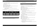
1.4.6 Battery Life
Table 1-22. Battery Life
Alkali Battery
LCD shooting
145 and more images (Old method) / 200 and more images
(New method)
Viewfinder shooting
1000 images or more
Playback
210 minutes
The battery life depends on measurement conditions. The measurement method is
provided by EPSON. The conditions are followings;
Product Description
Interface Specifications
26
PhotoPC 2100Z
Revision B
LCD SHOOTING
1.4.7 Power Saving Specifications
Old method
This section provides the power saving specifications for PhotoPC 2100Z.
1.
Turn on camera, then strat shooting in one minutes interval.
1.4.7.1 Shooting Mode
2.
No zoom operation, and 50% flash emission.
BATTERY
3.
Repeat Step1 and 2.
Power saving mode 1 (The camera enters this mode after 2 minutes of no
operation)
New method
1.
Turn on camera and leaves for 30 seconds, and start shooting 30
seconds interval for 10 times.
2.
Shoot and zoom operation between wide end and telescopic end,
and 50% flash emission.
3.
Turn off the camera for 10 minutes and more after 10 times.
4.
Repeat Step 1 to 3.
VF SHOOTING
Continuous shooting
No zoom operation
Flash is off.
Power saving mode 1 is entered after displaying icon animation.
Restoration condition: The camera is restored to the normal status by one of the
following events:
The Shutter Button is pressed.
The Playback Button is pressed.
One of the buttons (including the DPOF button) on the back is pressed.
The W/T Button is pressed.
The communication cable is connected.
When the communication cable is connected, the camera enters the
communication mode.
NOTE: In the case where the camera enters the power saving mode from flash off
status, the flash will not be charged at restoration from power saving mode.
PLAYBACK
Frame forwarding interval one minutes.
Product Description
Interface Specifications
27
PhotoPC 2100Z
Revision B
Power saving mode 2 (The camera enters this mode from power saving mode 1
1.4.7.2 Playback Mode
after 30 seconds of no operation)
Restoration condition: The camera is restored to the normal status by one of the
following events:
The Shutter Button is pressed.
The Playback Button is pressed.
One of the buttons (including the DPOF button) on the back is pressed.
The W/T Button is pressed.
The communication cable is connected.
When the communication cable is connected, the camera enters the
communication mode.
Complete OFF (Power is turned off from the power saving mode 2 after 2 minutes
of no operation)
BATTERY
Power saving mode 1 (The camera enters this mode after 2 minutes of no
operation)
Power saving mode 1 is entered after displaying icon animation.
Restoration condition: The camera is restored to the normal status by one of the
following events:
Table 1-23. Camera Status
Default
Power Saving Power Saving
Mode 1
Mode 2
Complete
OFF
LED
ON
ON
ON *1
OFF
LCD Monitor
ON
OFF
OFF
OFF
Lens
ON
ON
ON
OFF
CPU
ON
ON
OFF
*2
OFF
Note: *1: The orange LED flashes (Duty is changed).
*2: Startup time is longer than in the viewfinder mode (because of CPU shutdown).
AC ADAPTER
The camera enters the power saving mode1 after 15 minutes of no operation. After
further 5 minutes of no operation, power will turn completely off.
The Shutter Button is pressed.
The Playback Button is pressed.
One of the buttons (including the DPOF button) on the back is pressed.
The W/T Button is pressed.
The communication cable is connected.
When the communication cable is connected, the camera enters the
communication mode.
The Lens Cover Switch is set to the “Open” position.
When the Lens Cover Switch is set to the “Open” position, the camera enters
the shooting mode.
Power saving mode 2 (The camera enters this mode from power saving mode 1
after 30 seconds of no operation)
Restoration condition: The camera is restored to the normal status by one of the
following events:
The Shutter Button is pressed.
The Playback Button is pressed.
One of the buttons (including the DPOF button) on the back is pressed.
The W/T Button is pressed.
The communication cable is connected.
When the communication cable is connected, the camera enters the
communication mode.
The Lens Cover Switch is set to the “Open” position.
When the Lens Cover Switch is set to the “Open” position, the camera enters
the shooting mode.
Product Description
Interface Specifications
28
PhotoPC 2100Z
Revision B
Complete off (Power is turned off from the power saving mode 2 after 2 minutes
1.4.7.4 SETUP Mode
of no operation)
BATTERY
Table 1-24. Camera Status
Power Saving Power Saving
Mode 1
Mode 2
Default
Complete
OFF
Power saving mode 1 (The camera enters this mode after 2 minutes of no
operation)
LED
ON
ON
ON *1
OFF
Power saving mode 1 is entered after displaying icon animation.
LCD Monitor
ON
OFF
OFF
OFF
Lens
ON
ON
ON
OFF
Restoration condition: The camera is restored to the normal status by one of the
following events:
CPU
ON
ON
OFF *2
OFF
Note: *1: The orange LED flashes (Duty is changed).
*2: Startup time is longer than in power saving mode 1.
AC ADAPTER
The camera enters the power saving mode1 after 15 minutes of no operation. After
further 5 minutes of no operation, power will turn completely off.
The Shutter Button is pressed.
The Playback Button is pressed.
One of the buttons (including the DPOF button) on the back is pressed.
The W/T Button is pressed.
The communication cable is connected.
When the communication cable is connected, the camera enters the
communication mode.
Power saving mode 2 (The camera enters this mode from power saving mode 1
after 30 seconds of no operation)
1.4.7.3 Communicate Mode
Restoration condition: The camera is restored to the normal status by one of the
following events:
Table 1-25. Communicate Mode
Communication
Battery
Power saving is not enabled in the communication mode.
AC Adapter
Power saving is not enabled in the communication mode.
The Shutter Button is pressed.
The Playback Button is pressed.
One of the buttons (including the DPOF button) on the back is pressed.
The W/T Button is pressed.
The communication cable is connected.
When the communication cable is connected, the camera enters the
communication mode.
Product Description
Interface Specifications
29
PhotoPC 2100Z
Revision B
Complete off (Power is turned off from the power saving mode 2 after 2 minutes
of no operation)
Table 1-26. Camera Status
Default
Power Saving Power Saving
Mode 1
Mode 2
Complete
OFF
LED
ON
ON
ON *1
OFF
LCD Monitor
ON
OFF
OFF
OFF
Lens
ON
ON
ON
OFF
CPU
ON
ON
OFF
*2
OFF
Note: *1: The orange LED flashes (Duty is changed).
*2: Startup time is longer than in the viewfinder mode (because of CPU shutdown).
AC ADAPTER
The camera enters the power saving mode1 after 15 minutes of no operation. After
further 5 minutes of no operation, power will turn completely off.
Product Description
Interface Specifications
30
PhotoPC 2100Z
Revision B
1.5 Accessories
AA alkali battery x 4
CF memory card 8MB
Hand strap
Instruction manuals (CR-ROM)
USB cable (Exclusive use with PhotoPC 2100Z)
CD-ROM install guide
Bundle software (EU, Asia only)
Photo Suite 3SE (Win)
Photo Suite 3 (Mac)
Photo Vista Full Version (Win/Mac)
Product Description
Accessories
31
PhotoPC 2100Z
Revision B
1.6 Option
AC ADAPTER
NI-MH BATTERY CHARGER
Model name:
Model name:
EU-40 (same as that for PhotoPC 3000Z)
Model number:
EU-38 (same as that for PhotoPC 800)
Model number:
B867081, B867131, B867091, B867101, B867121, B867101, B867111, B867151,
B867171
Input voltage:
B818171-0200, B818181-0100, B818173-0100, B818174-0200, B818175-0200,
B818178-0200, B818177-0200, B818182-0000
Input voltage:
AC100-240V, 50-60Hz, 30VA
Output voltage:
AC100-240V, 50-60Hz, 10VA
Output voltage:
DC1.2V, 490mA × 4
DC7.0V, 2.0A
NI-MH BATTERY
Charging time:
2.5 H (when 4 batteries are charged together)
Model name:
EU-24 (same as that for PhotoPC 3000Z)
NOTE: The battery charger is available in a set of one battery charger and four NiMH batteries.
Model number:
B818113-0100
Input voltage:
1.2 V per battery
Capacity
1500 mAH per battery
NOTE: Ni-MH batteries are available in a set of four pieces.
Product Description
Option
32
PhotoPC 2100Z
Revision B
1.7 Environmental Conditions
1.7.1 Operating Conditions / Storage Conditions
Temperature
Operation:
Storage:
5 to 35°C
-20 to 60°C
Humidity
Operation:
Storage:
30 to 80%, No condensation
10 to 80%, No condensation
Shock resistance
Storage:
G [TBD]
1.7.2 Power Supply Specifications
DC input voltage (AC adapter)
Average: 7.0 VDC
Maximum: The AC adapter (EU-40) made by Epson must be used.
Maximum DC input voltage
Maximum: The AC adapter (EU-40) made by Epson must be used.
1.7.3 Intended Location of Use
Environment:
Home, outdoors
Drip-proof:
Not supported
Product Description
Environmental Conditions
33
PhotoPC 2100Z
Revision B
1.8 Safety Standards & Reliability
1.8.1 EMI and Safety Standards
Table 1-27. EMI and Safety Standards
Market
USA
EMI and Safety Standards
FCC part15 subpart B class B
Canada
CSA C108.8 class B
Europe
EMC Directive 89 / 336 / EEC (CE Marking)
EN55022 Class B
EN61000-3-2 (When AC adapter is used)
EN61000-3-3 (When AC adapter is used)
EN55024-1
IEC801-2
IEC801-3
IEC801-4
EN 55022 (CISPR Pub.22) class B
Australia
AS/NZS 3548 class B
Taiwan
EMI: CNS13438-C6357
Korea
Korea electromagnetic wave regulation
Japan
VCCI class B
Product Description
Safety Standards & Reliability
34
PhotoPC 2100Z
Revision B
1.9 Prohibitions and Precautions
Never see the sun through the viewfinder.
Never use any AC adapter other than the specified one.
Never use any batteries other than the specified ones.
Remove the batteries when the camera is not to be used for a long time.
Do not insert or eject the CF card when power is on.
Before replacing the CF card with another one, disconnect USB connection first, if
connected, by the procedure specific to the OS and turn off the camera power.
Product Description
Prohibitions and Precautions
35
2
CHAPTER
OPERATING PRINCIPLES
PhotoPC 2100Z
Revision A
2.1 Overview
This chapter explains operating principles of PhotoPC 2100Z.
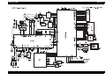
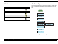
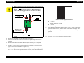
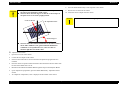
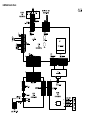
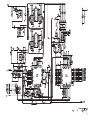
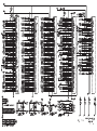
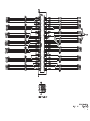
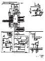
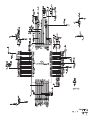
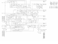
2.1.1 Circuit
The circuit block diagram of PhotoPC 2100Z is shown on the next page.
Operating Principles
Overview
37
PhotoPC 2100Z
Operating Principles
Revision A
Overview
38
PhotoPC 2100Z
Revision A
2.1.2 Operating Principles of Control Circuit
Table 2-1. Peripheral Elements of Main CPU (continued)
This section describes the functions of major elements constituting the circuitry of this
camera. The electric circuit of this camera is controlled by two CPUs, namely, the main
CPU and the 8-bit CPU.
Table 2-1. Peripheral Elements of Main CPU
Major Element
CCD
CDS & A/D
Main CPU
Functions
SDRAM
HYUNDAI HY57V653220BTC-10
Connected to the main CPU and used as the buffer memory for
image data, buffer memory for video data and memory for
program running.
Flash Memory
Sharp LHFA8E09
The program of the main CPU is written in.
Functions
Some area is used to record camera information.
Matsushita MN39471JT
Converts the image formed on the CCD by the lens into an
electrical signal.
1/2.6 inches, 2,310,000 pixels, complementary color filter,
interline transfer
Timing Generator (TG) Matsushita MN5296-1
This IC generates various drive waveforms to be given to the
CCD.
V Driver
Major Element
CompactFlash
Records taken pictures.
LCD Controller
EPSON EM1811D
Based on the video signal generated by the main CPU, the LCD
controller generates various signals which are necessary to drive
the LCD.
Color LCD Unit
EPSON L2B1600-B002
1.6-inch collar LCD, with backlight
237 (horizontal) × 234 (vertical) pixels
Matsushita MN31121SA
This IC drives the vertical transfer register of the CCD.
Analog Devices AD9843A
Converts analog signals given from the CCD into 10-bit digital
signals.
Incorporates a correlation double sampling circuit (CDS) to
remove the reset noise which can occur specifically with CCD.
Table 2-2. Peripheral Elements of 8-bit CPU
Major Element / Unit
Texas Instruments TMS320DSC21GHK
CPU and peripheral functions integration chip for digital camera
Signals for CCD, SDRAM controller, flash memory,
CompactFlash, USB, and video system interface are integrated.
At shooting, writes the digital data from the CCD circuit in
SDRAM and after image processing of the written data followed
by image compression, writes in the CompactFlash.
At playback, this CPU reads the data from the CompactFlash and
decompresses it, develops the image into DRAM and generates
the signal to send the image to the LCD by the Video Controller.
The CPU reads the program written in the flash memory, and
operates according to the program.
27MHz and 48MHz crystal oscillators are connected to the
oscillating circuit.
Operating Principles
Overview
8-bit CPU
Functions
UPD780055GK-A11
Detects the operations of all the switches for user interface
excepting the Release switch, controls all the LEDs, buzzer,
flash, shutter, focusing, zooming, battery check and DC-DC
converter (main power supply), and has a clock function.
Executes the above control by communication with the main
CPU.
Shutter
This shutter works also as the diaphragm.
Incorporated in the lens barrel.
Driven by the shutter driver LB1939T.
Controlled by the SMD__IN1, SMD_IN2 and SMD_EMA
signals from the 8-bit CPU.
39
PhotoPC 2100Z
Revision A
2.1.3 Operating Principles of Power Supply Circuit
Table 2-2. Peripheral Elements of 8-bit CPU (continued)
Major Element / Unit
Focusing Motor
Functions
2.1.3.1 Power Supply Voltages
Incorporated in the lens barrel to drive the lens for focusing.
Power supplies to PhotoPC 2100Z are as listed below. Each voltage is generated by the
voltage supplied from the batteries or the AC adapter.
The control signals, namely, FMD_IN1, FMD_IN2,
FMD_ENA and FMD_VCNT, from the 8-bit CPU are input
into the driver LB1839, which drives the Focusing Motor.
The photo-interrupter located in the lens barrel detects the
home position for focusing.
Zoom Motor
PC3.3V
3.3 V for CCD
The zoom motor, mounted in the lens barrel, drives the zoom
lens and retracts the lens barrel.
The control signals, ZM_IN1 and ZM_IN2, from the 8-bit
CPU, are input into the motor driver TK10205M, which drives
the zoom motor.
The position of the zoom lens is detected by the zoom lens
encoder mounted in the lens barrel.
Battery Check
occurs at a voltage of 2.5V.)
Clock
3.3 V for LCD
+1.8V
1.8 V for CPU
+D3.3V
The 8-bit CPU A/D converts and monitors the battery voltage.
A reset IC is mounted separately to ensure safety. (Resetting
DC-DC Converter
PL3.3V
Controls the power supply for the main CPU TMS320DSC21 by
the DD_OE1 and DD_OE2 signals from the 8-bit CPU.
3.3 V for LOGIC
+5V
For flash, CCD and LCD
+C18V
The 8-bit CPU, to which the crystal oscillator 32.768KHz
SSP-T5 is connected, has the clock function.
The lithium ion second battery MS614 for backup works to
maintain the clock function when the main batteries are
removed or the AC adapter is disconnected.
A reset IC is mounted so that clock operation is reset at the
minimum guarantee voltage 1.9 V of the 8-bit CPU.
18 V for CCD
+C16V
16 V for CCD
CM7V
-8 V for CCD
BK_8V
8 V for LCD backlight
A power supply circuit block diagram is shown on the next page.
Operating Principles
Overview
40
PhotoPC 2100Z
Revision A
[PS_block7019e.pdf]
Operating Principles
Overview
41
PhotoPC 2100Z
Revision A
2.1.3.2 Operating Principles of Power Supply Circuit
2.1.4 Operating Principles of Flash Circuit
The control IC (IC1) in the power supply circuit has a 2-channel control system. One
channel is used for voltage down by L81 to generate 3.3 V. The other channel is used
for voltage boosting and voltage down by the transformer T21 to generate four outputs,
namely, +3.3 V, +5 V, +18 V and -8 V.
The major functions of the flash circuit are to charge the flash capacitor at the flash
firing voltage and to fire the xenon flash lamp.
PC3.3V and PL3.3V are supplied from the 3.3 V of L81 by turning on and off the
switching circuit of Q91 and Q94.
Transformer T21 is a flyback circuit of +3.3 V.
The flash firing voltage is boosted to about 300 V by the oscillating transformer T3101
and charges the flash capacitor. The control signal ST_ON from the 8-bit CPU turns on
the transistor Q3105 to start flash charge. Flash charge is completed when Zener diode
D3106 sends the ST_OK signal to the 8-bit CPU.
The charge in the flash capacitor is applied to the trigger transformer T3102 by IGBT
Q3107 to fire the flash lamp. Flash firing is controlled by the DD_TRIG signal (5V
level).
+1.8V is generated from +3.3 V and stabilized by the regulator Q71.
+D3.3V is turned on and off by the switching circuit consisting of Q61 of +3.3 V.
+5V is stabilized by Q31.
+C18V is stabilized and turned on and off by Q41.
2.1.5 Fuses
+C16V is generated from +C18V and stabilized by Q161.
The power supply circuit has three fuses.
CM7V is generated from -8V and stabilized by Q51.
On the Main Circuit Board, a fuse is mounted for power to the motor.
BK_8V is generated by self-excitation transformer T1 and Q4.
The fuse for flash circuit is mounted on the Flash Circuit Board.
2.1.3.3 Power Supply Circuit on the Main Circuit Board
A power supply circuit (U1806) of 4.8 V is provided for motor drive.
To supply -32V for LCD brightness adjustment, the charge pump circuit U1603 is
provided.
2.1.3.4 Power Supply Circuit on Flash Circuit Board
The backlight is turned on by inverter (alternating current waveform) output of BK_6V
by t3103. The output connector is CN3104.
Operating Principles
Overview
42
3
CHAPTER
TROUBLESHOOTING
PhotoPC 2100Z
Revision A
3.1 Troubleshooting
Table 3-1. Troubleshooting (continued)
Problem
This section describes how to identify the defective unit or parts from observed
problems.
Possible Cause
Shorted CCD power supply
Replace Main Circuit Board.
Faulty operation of shutter
Check initial operation of shutter
at power on.
• If it does not operate, replace
Lens Unit (Lens Assy).
Taken pictures
are abnormal
CCD peripheral circuitry broken
down
Replace Main Circuit Board.
Problem with software
Check software version.
Install the latest version of
firmware.
Date setting
screen appears
every power on
Insufficient charging of the lithium
ion secondary battery
Replace Main Circuit Board if
replacement of batteries does not
solve problem.
Power does not
turn on
Batteries have run down
Replace the batteries.
Defective AC adapter or faulty
connection of AC adapter
Check AC adapter.
When lens cover switch is operated
• FFC of Release Circuit Board is
disconnected, or FFC broken
Check connection of connector
CN1103 on Main Circuit Board.
When playback button is pressed
• FFC of Rear Cover is disconnected,
or FFC broken
Check connection of connector
CN1104 on Main Circuit Board.
Faulty connection of board-to-board
connector
Check connection of connector
CN1102 on Main Circuit Board.
Faulty connection of pins BATT1
and BATT2, which connect Power
Supply Circuit Board to batteries
Check connection between pins
and Power Supply Circuit Board.
Blown fuse on Power Supply Circuit
Board
Replace Power Supply Circuit
Board.
Faulty operation of 8-bit CPU
Replace Main Circuit Board.
There is a short circuit somewhere, so
that Short-circuit protector of DC-DC
Converter on Power Supply Circuit
Board has operated.
Identify the location of short
circuit.
For example, CCD terminals.
Table 3-1. Troubleshooting
Problem
LCD shows
completely
white display at
shooting/
playback
LCD shows
completely black
display
Possible Cause
Checking and Remedy
Connector between LCD and Main
Circuit Board is disconnected, or
FFC of LCD broken.
Check connection of
Faulty operation of charge pump
which generates -32V in LCD circuit
Replace Main Circuit Board.
LCD backlight not lit
Check connection of connector
connectors CN1105 and 1106
on Main Circuit Board.
Replace LCD if FFC is broken.
CM3104 on Flash Circuit
Board.
Defective LCD
Replace LCD.
Defective backlight inverter circuit
on Flash Circuit Board
Replace Flash Circuit Board.
Black spots are
seen on LCD
Defective LCD monitor
Normal if 6 pixels or less
Bright spots are
seen on LCD
Defective LCD monitor
Replace LCD if more.
Troubleshooting
Low-bright spots (pixels seen
through 10% ND filter)
• Normal if 4 spots or less
• Replace LCD if more.
High-bright spots (pixels seen
through 5% ND filter)
• Normal if 1 spot
• Replace LCD if more.
Total of low- and high-bright
spots
• Normal if 4 spots or less in total
• Replace LCD if more.
Checking and Remedy
Taken pictures
are completely
black
Power turns on
once, but it turns
off immediately
Troubleshooting
44
PhotoPC 2100Z
Revision A
Table 3-1. Troubleshooting (continued)
Problem
Possible Cause
Checking and Remedy
Power does not
turn on, with the
camera beeping
Main CPU does not operate, so that
8-bit CPU has displayed an error.
Replace Main Circuit Board.
Flash memory firmware has
disappeared.
Replace Main Circuit Board.
Zooming, shutter
or auto focusing
does not work
Faulty connection of Lens Barrel
FFC on Main Circuit Board
Check to see if FFC is
disconnected from connector
CN1101 on Main Circuit Board.
Shutter does not
work
Flash does not
fire
Blown fuse for power to the motor
Replace Main Circuit Board.
Defective lens barrel
Replace lens barrel.
Faulty connection of FFC of Release
Circuit Board
Check to see if FFC is
disconnected from connector
CN1103 on Main Circuit Board.
Defective shutter switch
Replace Release Circuit Board.
Shutter release button is out of
position.
Check to see if shutter release
button is dislocated from its
position in Front Cover.
Defective Flash Circuit Board
Replace Flash Circuit Board.
Defective flash lamp
Replace flash lamp.
Defective lead wires of flash lamp
Replace flash lamp.
Defective 8-bit CPU
Replace Main Circuit Board.
Viewfinder LED
does not light up
Defective LED
Replace Main Circuit Board.
Self-timer LED
does not light up
Defective LED on Release Circuit
Board
Replace Release Circuit Board.
Switches in the
Rear Cover do
not work
FFC broken
Check to see if FFC is
disconnected from connector
CN1104 on Main Circuit Board.
Replace Rear Cover, if FFC is
broken.
Defective Main Circuit Board
Troubleshooting
Replace Main Circuit Board.
Troubleshooting
45
4
CHAPTER
DISASSEMBLY AND ASSEMBLY
PhotoPC 2100Z
Revision B
4.1 Overview
This section describes procedures for disassembling the main components of the
product.
W A R N IN G
Unless otherwise specified, disassembled units or components can be reassembled by
reversing the disassembly procedure.
Remove the batteries and plug off the AC adapter before
disassembling the camera.
Always wear gloves for disassembly and reassembly to avoid
4.1.1 Precautions
See the precautions given under the heading “WARNING” and “CAUTION” in the
following column when disassembling or assembling the product.
Things, if not strictly observed, that could result in injury or loss of life are described
under the heading “Warning”.
Precautions for any disassembly or assembly procedures are described under the
heading “CAUTION”.
1.
Chips for disassembling procedures are described under the heading “CHECK
POINT”.
2.
3.
If the assembling procedure is different from the reversed procedure of the
disassembling, the procedure is described under the heading “REASSEMBLY”.
Any adjustments required after disassembling the units are described under the heading
“ADJUSTMENT REQUIRED”.
4.
When you have to remove any units or parts that are not described in this chapter, refer
to the exploded diagrams in the appendix.
5.
Read precautions described in the next section before starting.
Disassembly and Assembly
Overview
injury from sharp metal edges.
The electrolytic capacitor (C3108) mounted on the circuit
board is to fire the flash and to be charged automatically
whenever the power is ON. Due to this, it may cause an electric
shock during the service procedure. Before starting repair, be
sure to discharge the camera, using the cement resistor. (For
details, refer to “Rear Cover Removal” on page 53.)
A lithium battery is installed on the main board of this camera.
Be sure to observe the following instructions when serving the
battery:
Keep the battery away from any metal or other batteries so that
electrodes of the opposite polarity do not come in contact with each
other.
Do not heat the battery or put it near fire.
Do not solder on any part of the battery. (Doing so may result in
leakage of electrolyte from the battery, burning or explosion. The
leakage may affect other devices close to the battery.)
Do not dismantle the battery. (The gas inside the battery may hurt
your throat. Leakage, burning or explosion may also be caused.)
Do not install the battery in the wrong direction. (This may cause
burning or explosion.)
Dispose of the used batteries according to government's law
and regulations.
To protect sensitive microprocessors and circuitry, use static
discharge equipment, such as anti-static wrist straps, when
accessing internal components.
To avoid dust explosion or ignition, never bring batteries close
to flame or throw them into fire.
47
PhotoPC 2100Z
Revision B
4.1.2 Tools
C A U T IO N
Use only recommended tools for disassembling, assembling or
Use only specified tools to avoid damaging the camera.
adjusting the camera.
Observe the specified torque when tightening screws.
Make the specified adjustments when you disassemble the
camera. (See Chapter 5 for details.)
For this product, there are two repair levels; first maintenance
and 2nd maintenance.
The service for second maintenance is allowed to be done only
by the service center equipped with special instruments for
adjustment. We do not guarantee the repair result performed
by the others.
Use the special package for transportation.
Prior to disassembly and reassembly, remove the accessories,
such as CF card.
Table 4-1. Tools
Name
Availability
Phillips precision screwdriver
{
Tweezers
{
Soldering iron
{
Solder suction tool
{
Tool Code
Battery Tool
EPSON
1091789
Color Viewer
EPSON
1030584
Strobo adjust chart
EPSON
1091791
AF adjustment chart
EPSON
RS-232C interface
EPSON
1091792
RS-232C cable
EPSON
1091790
Serial cable (serial 17-pin-DIN 7-pin)
EPSON
1104424
Stabilized DC power supply
Attached at the end of this
manual, A2 size
{
Note: “{”:available on the market, “EPSON”: available from EPSON
Disassembly and Assembly
Overview
48
PhotoPC 2100Z
Revision B
4.1.3 Screws
4.2 Disassembly
Table below shows the screws used with PhotoPC 2100Z.
Table 4-2. Screws
Name
SPB 1.7x2
Specification
SP BOLT 1.7x2 3x0.6
THB 2x6x3x0.6
THB 2.0x6.3x3.0x0.6
THB 1.7x4.0
THB 1.7x4.0-3.0x0.6
THB 1.7x5.5
THB 1.7x5.5-3.0x0.6
PS 2.0x6.0
PS-tite 2.0x6.0-3.0x0.6
Appearance
The flowchart below shows step-by-step disassembly procedure for PhotoPC 2100Z.
When disassembling each component, refer to the page number shown in the figure
below.
Figure 4-1. Disassembling Flowchart
Disassembly and Assembly
Disassembly
49
PhotoPC 2100Z
Revision B
4.2.1 Housing Disassembly
Hooks
4.2.1.1 Rear Cover Removal
1.
Remove the one screw (THB1.7x5.5) and the four screws (THB1.7x4.0) securing the
Rear Cover.
THB1.7x5.5
THB1.7x4.0
CN1104
THB1.7x4.0
Figure 4-3. Rear Cover Removal
THB1.7x4.0
3.
Disconnect the FFC of the Rear Cover from the connector CN1104 on the Main Circuit
Board. At this point, also the Battery Cap and the connector cover come off.
C H E C K
P O IN T
Figure 4-2. Rear Cover Securing Screws
NOTE: Tightening torque for screws THB1.7X5.5 and THB1.7x4.0: 0.12N⋅m
2.
When connecting the FFC, make sure that it is free from
slanting or floating insertion and be sure to lock the FFC
correctly.
Take care not to catch the FFC between the Front Cover and
the Rear Cover.
Disengage the two hooks with which the Rear Cover and the Front Cover are engaged,
and open the Rear Cover.
Disassembly and Assembly
Disassembly
50
PhotoPC 2100Z
W A R N IN G
Revision B
When the Rear Cover has been removed, the terminals of the
capacitor C3108 for flash firing appears at the upper left corner of
the camera. Be sure to discharge the capacitor using a cement
resistor. (Use a cement resistor with a resistance of about 500Ω to 1
kΩ/10W.)
4.2.1.2 Front Cover Removal
1.
Remove the Rear Cover. (See "Rear Cover Removal" on page 50)
2.
Remove the three screws (THB1.7x4.0) securing the Front Cover.
NOTE: Tightening torque for the screw THB1.7x4.0: 0.12N⋅m
THB1.7x4.0
Card Door
Terminals
Cement resistor
THB1.7x4.0
Figure 4-4. Front Cover Securing Screws
3.
Remove the Front Cover. At this point, the card door comes off together.
C H E C K
P O IN T
Disassembly and Assembly
Disassembly
Before installing the Front Cover, clean the inside of the lens
cover with a blower.
51
PhotoPC 2100Z
Revision B
4.2.1.3 Front Cover Disassembly
4.2.2 Disassembly of Circuit Boards
1.
4.2.2.1 Release Circuit Board Removal
Disengage the seven hooks fastening the Face Plate to the Front Cover.
1.
Remove the housing. (See "Housing Disassembly" on page 50)
2.
Disconnect the FFC of the Release Circuit Board from the connector CN1103 on the
Main Circuit Board.
3.
Remove the two screws (THB1.7x4.0) securing the Release Circuit Board.
NOTE: Tightening torque for the screw THB1.7x4.0: 0.12N⋅m
THB1.7x4.0
Figure 4-5. Fastening Hooks
2.
Remove the face cover.
C A U T IO N
CN1103
When the face cover is removed, the Flash Window and Selftimer Window come off together. Take due care not to lose any
parts.
The Viewfinder Window is fixed to the Front Cover with
double adhesive tape.
Figure 4-6. Release Circuit Board Securing Screws
4.
Remove the Release Circuit Board.
C H E C K
P O IN T
Disassembly and Assembly
Disassembly
When connecting the FFC, make sure that it is free from slanting
or floating insertion and be sure to lock the FFC correctly.
52
PhotoPC 2100Z
Revision B
4.2.2.2 Power Supply Circuit Board Removal
4.2.2.3 Monitor LCD Removal
1.
Remove the housing. (See "Housing Disassembly" on page 50)
1.
Remove the housing. (See "Housing Disassembly" on page 50)
2.
Remove the one screw (THB1.7x2.5) and the one screw (SPB1.7x4.0) securing the
Power Supply Circuit Board.
2.
Remove the Power Supply Circuit Board. (See "Power Supply Circuit Board Removal"
on page 53)
3.
Disconnect the harness for the backlight from the connector CN3104 on the Flash
Circuit Board.
NOTE: Tightening torque for the screws SPB 1.7x2.5 and THB1.7x4.0: 0.12N⋅m
SPB 1.7x2.5
THB1.7x4.0
CN3104
Figure 4-8. Connector CN3104
Figure 4-7. Power Supply Circuit Board Securing Screws
3.
Remove the Power Supply Circuit Board downward.
4.
Remove the one screw (SPB1.7x4.0) securing the Monitor Fixing Frame.
NOTE: Tightening torque for the screw SPB 1.7x2.5: 0.12N⋅m
C H E C K
P O IN T
When installing the Power Supply Circuit Board in the battery
box, make sure that the connector of the battery box and the
terminal of the circuit board are connected correctly, without
floating from each other.
Main Circuit Board
Upper hook
SPB1.7x4.0
Gasket
Hook
Hook
CN1105,1106
Figure 4-9. Monitor Fixing Frame Securing Screws
Disassembly and Assembly
Disassembly
53
PhotoPC 2100Z
Revision B
5.
Disengage the two hooks fastening the bottom end of the Fixing Frame to the Main
Circuit Board, and disengage the upper hook of the LCD from the Main Circuit Board.
6.
While lifting the Monitor LCD, disconnect the FFC from the connectors CN1105 and
CN1106 on the Main Circuit Board.
7.
Remove the Monitor LCD.
4.2.2.4 Flash Circuit Board Removal
1.
Remove the housing. (See "Housing Disassembly" on page 50)
2.
Remove the Power Supply Circuit Board. (See "Power Supply Circuit Board Removal"
on page 53)
3.
Peel off the insulating tape applied to the capacitor C3108 for flash firing.
Insulating tape
C H E C K
P O IN T
When connecting the FFC, make sure that it is free from
slanting or floating insertion and be sure to lock the FFC
correctly. Insert the FFC until its connecting portion is aligned
with the marking on the Main Circuit Board.
Marking
Figure 4-10. Insulating Tape
4.
Unsolder the three soldered joints of the Flash Tube lead wires with a soldering iron,
and remove the Flash Tube by inclining it clockwise slightly.
Soldered joints
C A U T IO N
Do not touch with bare hand the gasket of the Monitor LCD,
which is grounded to the switch circuit board of the Rear Cover.
Figure 4-11. Soldered Joints of Flash Tube Lead Wires
Disassembly and Assembly
Disassembly
54
PhotoPC 2100Z
C A U T IO N
Revision B
When soldering the Flash Tube lead wires, take care not to
produce any solder horn or bridge, which can cause abnormal
electric discharge.
C H E C K
P O IN T
When installing the Flash Circuit Board, make sure that the
circuit board is installed in the groove in the battery box.
Groove
発光
5.
Remove the one screw (SPB1.7x2.5) securing the Flash Circuit Board.
NOTE: Tightening torque for the screw SPB 1.7x2.5: 0.12N⋅m
SPB1.7x4.0
Figure 4-12. Flash Circuit Board Securing Screw
6.
Remove the Flash Circuit Board.
Disassembly and Assembly
Disassembly
55
PhotoPC 2100Z
Revision B
4.2.2.5 Battery Box Removal
6.
1.
Remove the housing. (See "Housing Disassembly" on page 50)
2.
Remove the Power Supply Circuit Board. (See "Power Supply Circuit Board Removal"
on page 53)
3.
Remove the Flash Circuit Board. (See "Flash Circuit Board Removal" on page 54)
4.
Remove the Eject Button from the CF card slot using tweezers, and place the Eject
Lever on the lens side.
5.
Remove the one screw (THB1.7x4.0) securing the copper foil and battery box.
Remove the one screw (THB1.7x4.0) securing the Main Circuit Board and Battery
Box.
NOTE: Tightening torque for the screw THB1.7x4.0: 0.12N⋅m
THB1.7x4.0
NOTE: Tightening torque for the screw THB1.7x4.0: 0.12N⋅m
Copper foil
Eject Button
Pin
Figure 4-14. Main Circuit Board / Battery Box Securing Screw
7.
Disengage the pin of the Battery Box from the Main Circuit Board.
THB1.7x4.0
Figure 4-13. Copper Foil Securing Screws
C A U T IO N
Do not touch the copper foil with a bare hand. A surface of the
copper foil oxidized due to soiling could lower the capacity to resist
radiation noise.
Disassembly and Assembly
Disassembly
56
PhotoPC 2100Z
Revision B
PCB Fixing Frame
Hook of Battery Box
4.2.2.6 Lens Assy (Lens & CCD Unit) Removal
1.
Remove the housing. (See "Housing Disassembly" on page 50)
2.
Remove the Power Supply Circuit Board. (See "Power Supply Circuit Board Removal"
on page 53)
3.
Remove the Flash Circuit Board. (See "Flash Circuit Board Removal" on page 54)
4.
Remove the Battery Box. (See "Battery Box Removal" on page 56)
5.
Disconnect the FFC connecting the Lens Assy to the Main Circuit Board from the
connector CN1101 on the Main Circuit Board.
PCB Fixing Frame
Pin of Battery Box
PS 2.0x6.0
CN1101
Figure 4-15. Hook and Pin of Battery Box
8.
Disengage the hook and pin of the Battery Box from the PCB Fixing Frame.
9.
Remove the Battery Box.
Lens Assy
PS 2.0x6.0
Figure 4-16. Lens Assy
6.
Disassembly and Assembly
Disassembly
Using a solder suction tool, remove the solder from the CCD terminals at which the
Lens Assy is soldered to the Main Circuit Board.
57
PhotoPC 2100Z
Revision B
NOTE: Tightening torque for the screw SPB 1.7x2.5: 0.12N⋅m
CCD terminals
SPB1.7x2.5
C A U T IO N
Do not remove the two black screws of the Lens Assy, which
connect the CCD and the lens barrel to each other. If you remove
them, dust or other foreign matters could adhere to the CCD.
Black screw
Black screw
SPB1.7x2.5
Figure 4-17. CCD Terminals
C A U T IO N
7.
When soldering the CCD terminals, solder the grounding
terminal of CCD first. This is intended to prevent the effect of
static electricity.
When soldering the CCD terminals, make sure that the
soldered joints are free from soldering defects, such as solder
bridge or solder spikes.
When connecting an FFC to the connector, make sure that it is
free from floating or slanting insertion or incomplete lock by
the connector.
Remove the two screws (PS 2.0x6.0) which secure the PCB Fixing Frame to the Lens
Assy. (See Figure 4-16)
NOTE: Tightening torque for the screw PS 2.0x6.0: 0.25N⋅m
8.
Remove the three screws (SPB 1.7x2.5) which secure the Lens Assy and PCB Fixing
Frame to the Main Circuit Board, and remove the Lens Assy, together with the PCB
Fixing Frame, from the Main Circuit Board. (See Figure 4-17)
Disassembly and Assembly
Disassembly
58
5
CHAPTER
ADJUSTMENT
PhotoPC 2100Z
Revision E
5.1 Overview
This section describes the adjustments required according to service components once
they have been replaced and also describes procedures for such adjustments.
The table below shows the adjustments required when components have been replaced.
Table 5-1. Adjustments Required Once Relevant Components have been Replaced
Sequence in which Adjustments should be Made
Service Components
1. Firmware
Installation
2. BC Compensation
3. LCD
Compensation
4. CCD Adjustment
5. AF Compensation
6. Strobo adjust
7. USB ID Writing
{
Flash Tube
Battery Box
{
Front Cover
{
Rear Cover
Battery Cap
{
Lens Assy
{
{
{
PCB Fixing Frame
Monitor Fixing Frame
Monitor Window
Eye-piece Window
Connector Door
Card Door
Eject Button
Main Circuit Board
{
{
{
{
{
{
Release Circuit Board
{
Flash Circuit Board
{
8P FFC
{
{
Monitor LCD
Power Supply Unit (DC/
DC Unit)
Note:
{
{
{
{
{
{
{: Required
Adjustment
Overview
60
PhotoPC 2100Z
Revision E
5.2 Tools
C A U T IO N
5.2.1 Tools
The PC to be used must be of a model which permits use of the
USB interface on Windows 98 or a later operating system.
Only one program file must be stored in one CF card if the file
The table below lists the tools needed for adjustments of PhotoPC 2100Z.
Table 5-2. Adjusting Tools
Adjustment Items
BC adjustment
Tool
Battery Tool
Tool Code
1091789
LCD adjustment
RS-232C I/F
1091792
RS-232C cable
1091790
LCD adjustment / USB ID writing
Serial cable
1104424
CCD gain adjustment, shutter
compensation and black defect input
& white defective compensation
Color viewer
1030584
Strobo adjustment
Strobo adjust chart
1091791
AF adjustment
AF adjustment chart
Attached at the end of
this manual
5.2.2 Adjustment Programs
The adjustment items require the respective adjustment programs. For use, register
adjustment programs in CF cards, respectively.
Table below shows the adjustment items and files.
Table 5-3. Adjustment Programs
Adjustment Item
“BC (Battery Check) Compensation Value Writing”
“LCD (Brightness) Adjustment”
“CCD Gain Adjustment, Shutter Compensation Black
Defect Writing and White defect compensation”,
“Strobo Adjustment”
“AF (Auto Focus) Compensation”
“USB ID Writing”
Adjustment
name has an extension “c21”. If two or more program files with
an extension “c21” are stored in one CF card, proper selection
of the program to be executed by the camera will not be
ensured.
When storing a program in a CF card, pay attention to the
property of the file. If the property is “read only”, the camera
can not execute the program. And, check a mark on the archive
check box in the property, otherwise the camera can not
execute it too.
When all the adjustments to be made, perform “BC (Battery
Check) Compensation Values Writing” first. The other
adjustments can be performed in any sequence. These
adjustments include the initialization of the adjusted value
storage area in the camera.
Once “BC (Battery Check) Compensation Values Writing” is
performed, be sure to perform all the other adjustments
subsequently, without omitting any of them.
Once any error occurs during execution of an adjustment,
perform the same adjustment again under the same conditions.
(See "Explanation of Error Codes" on page 62)
If an error recurs, check for proper conditions under which the
adjustment is performed.
When performing any of the CCD adjustment, AF adjustment
and Strobo adjust, make sure that the lens cover is open.
File Name
BC.c21
1. CRT21ma.exe
2. LCD.c21
CCD.c21
Strobe.c21
AF.c21
1. CRT21sp.exe
2. USB.c21
Tools
61
PhotoPC 2100Z
C A U T IO N
Revision E
Without firmware installation, the adjustment by CF
5.2.3 Explanation of Error Codes
card has the counter that control to adjustment count on
each adjustment item. The counter is up to ten times.
When count up, the camera will not accept more
adjustment setting. At that time, perform the following
program;
Erase.c21
How to use is the same as another extension “c21” files.
But, if you perform the above program once, you must
perform the adjustments again from BC adjustment to
USB writing. Because, this program reset the adjustment
value without the firmware.
If any error occurs during execution of these adjustment programs, the LCD monitor of
the camera displays the error code. This section describes the errors signified by the
respective error codes and corrective actions to be taken at the occurrence of such
errors.
0: Any error other than specified
Corrective action
Perform the adjustment again.
1: Battery adjustment error
Corrective action
Check the conditions under which the adjustment is performed. For example,
check the power voltage and camera temperature.
2: CCD adjustment error
Corrective action
Check the conditions under which the adjustment is performed. Perform the
adjustment again and if a similar error recurs, replace the Lens Assy (with
CCD) with a new one.
3: CCD adjustment error
Corrective action
Check the conditions under which the adjustment is performed. Perform the
adjustment again and if a similar error recurs, replace the Lens Assy (with
CCD) with a new one.
4: CCD adjustment error
Corrective action
Check the conditions under which the adjustment is performed. Perform the
adjustment again and if a similar error recurs, replace the Lens Assy (with
CCD) with a new one.
5: Strobo adjustment error
Corrective action
Check the conditions under which the adjustment is performed. Perform the
adjustment again and if a similar error recurs, replace the PCB-Strobe Assy
with a new one.
Adjustment
Tools
62
PhotoPC 2100Z
Revision E
6: AF adjustment error
Corrective action
5.3 Adjustment
Check the conditions under which the adjustment is performed. Perform the
adjustment again and if a similar error recurs, replace the Lens Assy (with
CCD) with a new one.
20: Adjusted value writing error
Corrective action
5.3.1 Installation of firmware
5.3.1.1 Version Confirmation
1.
Check the conditions under which the adjustment is performed. Perform the
adjustment again and if a similar error recurs, replace the PCB-MCU Assy
with a new one.
Press the F Button and the SCROLL Button simultaneously, and the camera will enter
SETUP mode.
Shutter Button
30: Camera adjustment execution error
Corrective action
Check the conditions under which the adjustment is performed. Perform the
adjustment again and if a similar error recurs, replace the PCB-MCU Assy
with a new one.
40: Brightness box error
Corrective action
Check the conditions under which the adjustment is performed. Perform the
adjustment again and if a similar error recurs, replace the Lens Assy (with
CCD) with a new one.
Lens Cover Switch
C A U T IO N
Adjustment
These errors may occur on rare occasions. If any error occurs,
first check the conditions under which the adjustment is
performed.
Once the camera is disassembled or a new component or unit is
installed, be sure to check for proper reassembly or installation,
especially for proper connection of connectors.
Adjustment
63
PhotoPC 2100Z
Print Button
Revision E
5.3.2 BC (Battery Check) Compensation Value Writing
Playback Button
This adjustment is executed in order to input the threshold values for battery check into
flash memory on the Main Circuit Board. This adjustment includes the initialization of
the adjusted value storage area in the camera.
1.
Close the lens cover of the camera.
F Button
SCROLL Button
2.
Hold down the Print Button.
3.
The version of firmware is displayed on the LCD monitor at its top left.
5.3.1.2 Installation
1.
Copy firmware into a CF card beforehand.
2.
Make sure that power to the camera is OFF, and then set the CF card in the camera.
3.
While pressing the F Button and Shutter Button together, push Playback Button to turn
on power to the camera. The LCD will show “DOWNLOAD MODE” first and then
“ERASING FLASH”.
4.
Installation of firmware will automatically be started and upon completion of
installation, power to the camera will automatically turn off. (About 2 minutes)
C A U T IO N
Adjustment
Figure 5-1. Battery tool
2.
Install the battery tool (No.1091789) in the Battery Box of the camera.
3.
Connect the stabilized power supply to the battery tool. Set the voltage in the range of
3.95 to 4.05V.
When inserting or removing the CF card, make sure that
power to the camera is OFF. Especially, remember that
removal of the CF card during writing in the card could result
in a malfunction of the card.
For firmware installation, use the AC adapter. If power to the
camera turns off during installation of firmware, not only
installation can not be executed normally, but also flash
memory on the circuit board could be damaged.
C A U T IO N
Adjustment
Do not confuse the polarity of the cable of the battery tool;
Red cable: positive terminal, Black cable: negative terminal
Do not input the camera over 11V. Otherwise, the camera will
have serious damage.
64
PhotoPC 2100Z
Revision E
4.
Insert into the camera the CF card in which the BC compensation program has been
installed.
5.
Hold down the F Button and Shutter Button together and press the Playback Button,
and the BC compensation values will be written.
6.
BC compensation is completed when “OK” is displayed on the monitor of the camera.
7.
Press the shutter button fully to turn off power to the camera.
8.
Remove the CF card from the camera.
9.
Remove the battery tool from the camera.
5.3.3 LCD (Brightness) Adjustment
Adjust the brightness on the monitor to optimize the contrast of display on the monitor.
Adjusted values are written in flash memory on the Main Circuit Board.
1.
Open the lens cover of the camera.
2.
Connect the AC adapter and RS-232C cable (Part 1091790) to the camera.
RS-232C cable
Serial cable
RS-232C interface
Figure 5-2. LCD Adjustment
3.
Adjustment
Adjustment
Connect the RS-232C cable to the RS-232C interface (Part 1091792). Then connect
the RS-232C interface to the serial port of the PC with Serial cable (Part 1104424).
65
PhotoPC 2100Z
C A U T IO N
Revision E
With the PC having two or more serial ports, use COM1 port, if
possible.
When connect the camera to PC by the RS-232c interface,
connect the following figure. Do not misconnect the cables,
otherwise the RS-232C interface board may have damage.
AC Adopter
Serial cable
(For PC)
RS-232C
interface
Figure 5-4. LCD Adjustment Pattern
“+” button
Raise the brightness of LCD.
“-” button
Lower the brightness of the LCD.
9.
RS-232C cable
(For Camera)
10. Pressing the Shutter Button fully will turn off power to the camera to complete the
adjustment.
Figure 5-3. Cable connection
11. Remove the CF card from the camera.
12. Disconnect the AC adapter and the communication cable from the camera.
Connect the AC adopter EU-40 to the interface as a power
supply.
13. Pressing the “e” key will complete the adjustment program.
4.
Run the LCD adjustment program (CRT21ma.exe) on the PC.
5.
Insert into the camera the CF card in which the LCD adjustment program has been
installed.
6.
Hold down the F Button and Shutter Button together and then press the Playback
Button.
7.
Push the “+” button on the adjustment window of the PC until the adjustment patter
appears on the LCD monitor.(Refer to Figure 5-4.)
8.
While observing the monitor screen of the camera, adjust the brightness, by pressing
the “+” or “-” button on the adjustment window of the PC, so that both the black area
and white area are seen clear at the same time (a maximum contrast is observed).
Adjustment
Upon completion of brightness adjustment above, press the “Write” button on the
adjustment window of the PC, and the monitor of the camera will display “OK”.
Adjustment
66
PhotoPC 2100Z
Revision E
5.3.4 CCD Gain Adjustment, Shutter Compensation
Black Defect Writing and White defect
compensation
8.
Pressing the shutter button fully will turn off power to the camera.
9.
Remove the CF card from the camera.
The adjustments to be made here are CCD gain adjustment, shutter compensation and
compensation of CCD pixel defects (loss of pixels). Adjusted values are written in
flash memory on the Main Circuit Board.
11. Disconnect the AC adapter from the camera.
1.
Open the lens cover of the camera.
2.
Connect the AC adapter to the camera.
3.
Insert into the camera the CF card in which the program for CCD gain adjustment,
shutter compensation and black defect adjustment has been installed.
4.
Place the camera close to (at 10 mm or less from) the color viewer at its center.
10. Close the lens cover of the camera.
Less than 10 mm
Color Viewer
Figure 5-5. Placing the Camera in front of the Color Viewer
5.
Hold down the F Button and Shutter Button together and then the Playback Button, and
CCD gain adjustment, shutter compensation and black defect writing will be started.
6.
Upon completion of preparation, press the Shutter Button fully.
7.
The adjustment is completed when “OK” is displayed on the monitor of the camera.
Adjustment
Adjustment
67
PhotoPC 2100Z
Revision E
5.3.5 Strobo Adjustment
This process adjusts the amount of flash light with the lens positioned on the WIDE
(wide-angle) side and TELE (telescopic) side. Adjusted values are written in flash
memory on the Main Circuit Board. For this adjustment, use of a dark box or dark
room is desirable. Instead, however, you can use a room which is so prepared that no
external light enters directly.
Strobo adjust Chart
1m
Adjustment Procedure
1.
Open the lens cover of the camera.
2.
Connect the AC adapter to the camera.
3.
Insert into the camera the CF card in which the Strobo adjust program has been
installed.
4.
Place the camera at a position where the distance from the chart to the lens surface with
the lens on the WIDE side is 1 meter. In doing so, orient the camera correctly toward
the chart.
5.
Hold down the F Button and Shutter Button together and then press the Playback
Button.
6.
Upon completion of preparation, press the Shutter Button fully.
7.
The flash fires one time on each of the WIDE side and TELE side.
8.
At completion of adjustment, “OK” is displayed on the monitor of the camera.
9.
Press the Shutter Button fully to turn off power to the camera.
Dark Box / Dark Room
Figure 5-6. Strobo adjustment
Preparation for Adjustment
Stick six sheets of Strobo adjust charts (No.1091791) on a wall or board so
that there is no clearance between the six.
The wall or board to put those Strobo adjust charts on must be of a low
reflectivity. If the surface of the wall or board is bright, stick the charts on a
black sheet of paper wide enough.
To stick the six charts on the wall or board, use double adhesive tape between
the sheets and the wall or board so that no tape is seen from the camera side.
Adjustment
10. Remove the CF card from the camera.
11. Disconnect the AC adapter from the camera.
Adjustment
68
PhotoPC 2100Z
Revision E
5.3.6 AF (Auto Focus) Compensation
C A U T IO N
Do not move the camera during adjustment.
In this adjustment, the adjusted values for AF in-focus positions are written into flash
memory on the Main Circuit Board.
AF Adjustment Chart
70 cm
Figure 5-7. AF Compensation
Preparation for Adjustment
Stick the AF adjustment chart on a wall or board. The AF adjustment chart to
be used is found at the end of this manual and can be obtained by outputting
the attached file “sn_chart.dxf” onto an A2 size sheet.
Place the camera in such a way that the center of the camera lens is in
alignment with the center of the chart.
The camera position is considered acceptable as long as the center of the chart
is not dislocated as viewed on the LCD monitor of the camera.
Adjustment
Adjustment
69
PhotoPC 2100Z
C A U T IO N
Revision E
If a printed chart is to be used, make sure that the pattern of
the chart is not incomplete, soiled or blur.
Slant the chart about 25 degrees so that the vertical stripes of
8.
Press the Shutter Button fully to turn off power to the camera.
9.
Remove the CF card from the camera.
10. Disconnect the AC adapter from the camera.
the pattern are never in the upright position.
C A U T IO N
Center of the lens
Do not move the camera during adjustment.
AF Adjustment Chart
About 25 degrees
Since the allowable ambient illumination at the chart surface is
about 300 to 1000 luces, the general ambient illumination
conditions are acceptable. However, take care that too
intensive light does not hit the chart.
Adjustment Procedure
1.
Open the lens cover of the camera.
2.
Connect the AC adapter to the camera.
3.
Insert into the camera the CF card in which the AF adjustment program has been
installed.
4.
Place the camera at a position where the distance from the chart to the lens surface with
the lens on the WIDE side is 70 cm.
5.
Hold down the F Button and Shutter Button together and press the Playback Button.
6.
Upon completion of preparation, press the Shutter Button fully. Adjustment will be
started
7.
At completion of adjustment, “OK” is displayed on the monitor of the camera.
Adjustment
Adjustment
70
PhotoPC 2100Z
Revision E
5.3.7 USB ID Writing
In this adjustment, the USB ID is written in flash memory on the Main Circuit Board.
When the Main Circuit Board has been replaced with a new one, the camera can not
use the USB ID which is stored on the old circuit board. Therefore, make this
adjustment to register a new USB ID on the new circuit board.
C A U T IO N
If the display shows “A camera number can't be inputted” during
USB ID writing, it signifies that the USB ID is not written
successfully. In such a case, follow the USB ID writing procedure
again.
Adjustment Procedure
1.
Connect the camera to PC by the serial cable to the camera via RS-232C interface. (See
"LCD (Brightness) Adjustment" on page 65)z
2.
Turn on power to the PC and run the adjustment program (CRT21sp.exe).
3.
Insert into the camera the CF card in which the USB ID writing program has been
installed.
4.
Hold down the F Button and Shutter Button together and press the Playback Button.
Then power to the camera will turn on and the viewfinder LED will blink.
5.
The window as shown below will appear. Then enter the 6-digit serial number.
6.
Upon completion of input, press the “W” key on the keyboard of the PC (“write”
button), and the PC and the monitor of the camera will display “OK”.
7.
Pressing the Shutter Button fully will turn off power to the camera to complete the
adjustment.
8.
Remove the CF card from the camera.
9.
Disconnect the AC adapter and the communication cable from the camera.
10. Pressing the “e” key (“exit” button) will complete the adjustment program.
Adjustment
Adjustment
71
6
CHAPTER
MAINTENANCE
PhotoPC 2100Z
Revision B
6.1 Overview
PhotoPC 2100Z requires no specific maintenance (lubrication / adhesion / cleaning).
Camera should be cleaned according to its necessity, however, such as for dust
incoming at the repairing service or fingerprint. The following table lists the check
items before sending the camera back to users
6.1.1 Check Items before Shipment
Check the camera according to Table 6-2. If you find any dust or dirt on the camera,
clean it referring to Chapter 4 “Disassembly and Assembly”. Clean the camera of dust
and fingerprints by the method as described in Table 6-1 below.
Table 6-2. Check Items before Shipment
No.
Exterior casing
Cleaning Method
• Wipe with a soft dry cloth.
• If the dirt is heavy, first remove it with a soft cloth which has
been dipped in a neutral detergent diluted with water and then
squeezed up. After that, wipe with a soft dry cloth.
Lens
Blow the dust off by a blower or an air blush. Then gently wipe
with a soft cloth.
Monitor LCD
Gently wipe with a soft dry cloth.
Flash window
Gently wipe with a soft dry cloth.
Self-timer window
Gently wipe with a soft dry cloth.
C A U T IO N
OK/NG
1
What is firmware version? Ver.
OK
NG
2
Are the inside and outside of the lens viewer free from
fingerprints or any other soiling.
OK
NG
3
Are the inside and outside of the flash window free from
dust or foreign matter adhesion?
OK
NG
4
Is the lens surface free from fingerprints or dust?
OK
NG
5
Are the inside and outside of the Monitor LCD window
free from fingerprints or dust?
OK
NG
6
Has the Battery Cover been installed in the Rear Cover
properly and does it open and close normally, with a click
felt?
OK
NG
7
Does the camera ensure normal insertion of the
CompactFlash card?
OK
NG
8
Has the Connector Cover been installed in the Rear Cover
properly and does it open and close normally, with a click
felt?
OK
NG
9
Do all the switch buttons operate properly?
10
Is the appearance clean?
OK
NG
OK
NG
11
Have all the accessories installed in position or packed
together for delivery, without forgetting any of them?
OK
NG
Table 6-1. Places to be Cleaned and Cleaning Method
Places to be Cleaned
Check Item
Pay special attention to dirt or scratches on the flash window,
which can cause the flash window to be deformed.
Remember that dirt or scratches on the flash window can also
cause abnormal flash firing.
Maintenance
Overview
73
7
CHAPTER
APPENDIX
PhotoPC 2100Z
Revision A
7.1 Circuit Board Connection Diagram
The next page shows the circuit board connection diagram.
Appendix
Circuit Board Connection Diagram
75
PhotoPC 2100Z
Revision A
7.2 Circuit Board Component Layout
This section shows the circuit board component layouts for PhotoPC 2100Z.
Figure 7-1. Main Circuit Board 1
Appendix
Circuit Board Component Layout
77
PhotoPC 2100Z
Revision A
Figure 7-2. Main Circuit Board 2
Appendix
Circuit Board Component Layout
78
PhotoPC 2100Z
Revision A
Figure 7-3. Release Circuit Board (Components Side)
Appendix
Circuit Board Component Layout
Figure 7-4. Release Circuit Board (Solder Side)
79
PhotoPC 2100Z
Revision A
Figure 7-6. Flash Circuit Board 2
Figure 7-5. Flash Circuit Board 1
Appendix
Circuit Board Component Layout
80
PhotoPC 2100Z
Revision A
7.3 Circuit Diagrams
This section shows the following circuit diagrams for PhotoPC 3100Z.
Circuit Diagram of Main Circuit Board 1-8
Circuit Diagram of Release Circuit Board
Circuit Diagram of Flash Circuit Board
Circuit Diagram of Power Supply Circuit Board
Appendix
Circuit Diagrams
83
PhotoPC 2100Z
Revision A
7.4 Exploded Diagrams
This section shows exploded diagrams.
The parts to which no reference number
is assigned will not be available as
after-sale service parts.
101
505
103
104
505
505
105
102
FOR CP-80Z/PHOTO PC2100Z NO.1
Appendix
Exploded Diagrams
Rev.01 B150
95
PhotoPC 2100Z
Revision A
The parts to which no reference number
is assigned will not be available as
after-sale service parts.
503
503
205
502
500
503
114
201
501
504
FOR CP-80Z/PHOTO PC2100Z NO.2
Appendix
Exploded Diagrams
Rev.01 B150
96
PhotoPC 2100Z
Revision A
The parts to which no reference number
is assigned will not be available as
after-sale service parts.
505
204
202
100
113
FOR CP-80Z/PHOTO PC2100Z NO.3
Appendix
Exploded Diagrams
Rev.01 B150
97
PhotoPC 2100Z
Revision A
The parts to which no reference number
is assigned will not be available as
after-sale service parts.
203
200
112
505
206
503
109
FOR CP-80Z/PHOTO PC2100Z NO.4
Appendix
Exploded Diagrams
Rev.01 B150
98
PhotoPC 2100Z
Revision A
The parts to which no reference number
is assigned will not be available as
after-sale service parts.
111
107
110
506
505
508
507
505
108
505
505
FOR CP-80Z/PHOTO PC2100Z NO.5
Appendix
Exploded Diagrams
Rev.01 B150
99
PhotoPC 2100Z
Revision A
7.4.1 ASP List
Table 7-1. ASP List
The Ref. Nos. correspond to the numbers shown in the exploded diagrams.
Table 7-1. ASP List
Part Name
Ref. No.
Sales Part Code
101
1083774
FRONT COVER ASSY.
102
1083775
FACE PLATE
103
1083776
VF WINDOW
104
1083777
SELF WINDOW
105
1083778
STROBE WINDOW
107
1083780
REAR COVER ASSY.
108
1083783
MONITOR SW SET
110
1083801
MONITER WINDOW
111
1083802
EYEPIECE WINDOW
505
1083858
SCREW THB 1.7X4.0-3.0X0.6
505
1083858
SCREW THB 1.7X4.0-3.0X0.6
506
1083868
SCREW THB 1.7X5.5-3X0.6
507
1083781
MONITOR GASKET
508
1083782
REAR PLATE
100
1083773
BATTERY BOX SET
109
1083784
BATTERY CAP ASSY.
112
1083803
CONNECTOR DOOR
113
1083804
CARD DOOR
114
1083805
EJECT BUTTON
200
2056376
FLASH TUBE ASSY.
201
2056394
PCB-MCU ASSY.
202
2056395
PCB-RELEASE ASSY.
203
2056396
PCB-STROBE ASSY.
204
2056397
8P FFC 0.5P
205
2056398
MONITOR LCD
206
2056399
DC/DC UNIT
Appendix
Part Name
Ref. No.
Sales Part Code
500
1083785
LENS ASSY.
501
1083786
RETAINER PCB
502
1083787
RETAINER MONITOR
503
1083856
SCREW SP BOLT 1.7X2-3X0.6
503
1083856
SCREW SP BOLT 1.7X2-3X0.6
504
1083857
SCREW THB 2X6X3X0.6
505
1083858
SCREW THB 1.7X4.0-3.0X0.6
505
1083858
SCREW THB 1.7X4.0-3.0X0.6
Exploded Diagrams
100
PhotoPC 2100Z
Revision A
7.5 AF Adjustment Chart
The AF adjustment chart is shown on the next page. For use, output the chart with the
A2 size. (See "AF (Auto Focus) Compensation" on page 69)
Appendix
AF Adjustment Chart
101