1
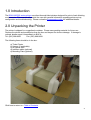
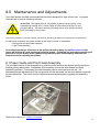
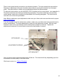
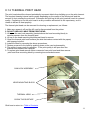
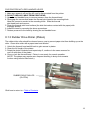
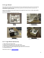
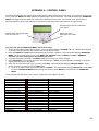
MICRO MODEL TICKET PRINTERS Operator’s Manual Rev A: 10/16/2002 0,&52 0,&523/86 6XE0,&52 '8$/0,&52 0 Table of Contents Page FCC Notice & Warranty Information 2 1.0 Introduction 3 2.0 Unpacking the printer 3 3.0 Important Safety Information 4 4.0 Installation 5 5.0 Configuration 5 6.0 Standard Interface Pinouts 6 7.0 Thermal Paper – Theory & Specifications 7 8.0 Maintenance and Adjustments 8 8.1 Paper Guide and Print Head Assembly 8 8.1.1 Load Switch and Tear Opto 9 8.1.2 Thermal Print Head 11 8.1.3 Rubber Drive Roller 12 8.1.4 Ticket Width Adjustment 13 Logic Board 14 8.2.1 Logic Board (Removal) 14 8.2.2 Logic Board (Installation) 15 General Cleaning 15 8.2 8.3 9.0 Spare Parts List 15 10.0 Troubleshooting Guide 18 Appendix A 20 1 FCC NOTICE NOTE: The equipment has been tested and found to comply with the limits for a class A digital device, pursuant to part 15 of the FCC rules. These limits are designed to provide reasonable protection against harmful interference when the equipment is operated in a commercial environment. This equipment generates, uses, and can radiate radio frequency energy and , if not installed and used in accordance with the instruction manual, may cause harmful interference to radio communications. Operation of this equipment in a residential area is likely to cause harmful interference in which case the user will be required to correct the interference at his own expense. Operation is subject to the following two conditions: 1. This device may not cause harmful interference, and 2. This device must accept any interference received, including interference that may cause undesired operation. NOTE: This unit was tested with shielded cables on the peripheral devices. Shielded cables must be used with the unit to insure compliance. WARRANTY INFORMATION PRINTERS - BOCA warrants each printer to be free of defects for a period of one year from the date of shipment when subject to normal use and service. This warranty covers all parts and labor except for the print head, which is warranted for 90 days. All warranty labor is to be performed at the BOCA facility. Equipment damaged by misuse or negligence, including damage to print heads caused by defective ticket stock, is excluded from this warranty. Any defective equipment meeting these conditions should be returned to BOCA for repair (freight prepaid) in its original box and packing material. A short note describing the failure should be enclosed with the printer. Equipment damaged in shipping should be reported immediately both to BOCA and to the shipper. EXTENDED WARRANTY PLAN - BOCA offers extended warranty plans for all printer models. These plans cover all parts and labor. All labor is to be performed at the BOCA facility. Equipment damaged by misuse or negligence, including damage to print heads caused by defective ticket stock, is excluded from this extended warranty. The customer, at its option, may request BOCA to ship individual parts to expedite simple repair procedures. In certain cases where the customer is unable to wait for the normal repair cycle, BOCA will ship an exchange printer within one business day after notification by the customer. All freight charges are the responsibility of the customer. Click here to return to > Table of Contents 2 1.0 Introduction The BOCA MICRO series printers are direct thermal ticket printers designed for point of sale ticketing environments. This manual will provide the user with general information regarding printer set-up, configuration and troubleshooting. Please review the programming guide for additional details. 2.0 Unpacking the Printer The printer is shipped in a ruggedized container. Please save packing material for future use. Remove the printer and accessories from the box and inspect for obvious damage. If damage is noticed, please report it immediately to BOCA. Tel: (561) 998-9600 Fax: (561) 998-9609 The following items should be in the box: a) Ticket Printer b) Hopper (if applicable) c) AC power cord d) Interface cable (optional) e) Mounting Plate (optional) Click here to return to > Table of Contents 3 3.0 Important Safety Information :$51,1*7KHDSSHDUDQFHRIWKLVV\PEROLQGLFDWHVWKHSUR[LPLW\RIDQ H[SRVHGKLJKYROWDJHDUHD3OHDVHIROORZDOOGLUHFWLRQVFDUHIXOO\IRU\RXU SHUVRQDOVDIHW\<RXPXVWUHDGWKHIROORZLQJVDIHW\LQIRUPDWLRQFDUHIXOO\ EHIRUHZRUNLQJRQWKHSULQWHU As a safety precaution, all service to the printer should be done by qualified persons with power off and the AC cord unplugged from the printer. Following any procedure requiring the removal of covers and/or doors, please verify that they have been properly attached and fastened prior to operating the printer. WARNING: "Provide an earthing connection before the mains plug is connected to the mains. And, when disconnecting the earthing connection, be sure to disconnect after pulling out the mains plug from the mains." WARNING: Power Cord Set: This must be approved for the country where it is used: U.S.A. and Canada The cord set must be UL-approved and CSA certified. The minimum specification for the flexible cord is: No. 18 AWG Type SV or SJ 3-conductor The cord set must have a rated current capacity of at least 10A. The attachment plug must be an earth-grounding type with a NEMA 5-15P (15A, 125V) or NEMA 6-15P (15A, 250V) configuration. United Kingdom only The supply plug must comply with BS1363 (3-pin 13 amp) and be fitted with a 5A fuse which complies with BS1362. The mains cord must be <HAR> or <BASEC> marked and be of type H03VVF3GO.75 (minimum). Europe only: The supply plug must comply with CEE 7/7 (“SCHUKO”). The mains cord must be <HAR> or <BASEC> marked and be of type H03VVF3GO.75 (minimum). Denmark : The supply plug must comply with section 107-2-D1, standard DK2-1a or DK2-5a. Switzerland: The supply plug must comply with SEV/ASE 1011. WARNING: The appliance coupler (the connector to the unit and not the wall plug) must have a configuration for mating with an EN60320/IEC320 appliance inlet. WARNING: The socket outlet must be near to the unit and easily accessible. WARNING: France and Peru only: This unit cannot be powered from IT† supplies. If your supplies are of IT type, this unit must be powered by 230V (2P+T) via an isolation transformer ratio 1:1, with the secondary connection point labelled Neutral, connected directly to earth (ground). WARNING: RJ-45 Ports. These are shielded RJ-45 data sockets. They cannot be used as standard traditional telephone sockets, or to connect the unit to a traditional PBX or public telephone network. Only connect RJ-45 data connectors. Either shielded or unshielded data cables with shielded or unshielded jacks can be connected to these data sockets. 4 4.0 Installation The BOCA MICRO series printer was designed to be mounted either on a desktop or shelf (horizontal model) or vertically in a counter top (vertical model). Prior to site preparation and installation, the printer should be powered up and run in the self-test mode. • Lay the printer flat on a counter top with the cover open. • Attach the AC cord and interface cable into the proper connectors. • Turn power on. After initializing, the LCD will display PAPER OUT. • Begin loading tickets through the entrance slot with a smooth motion until the printer automatically positions the ticket. NOTE: Tickets should be loaded with the black mark facing down. Refer to the BOCA systems website at www.bocasystems.com, THERMAL TICKETS section for ticket specifications. • After the ticket is automatically positioned (the READY LED will be illuminated), press the TEST button located on the control panel to print a test ticket. • Verify that the printer properly works with your system by issuing a ticket through your computer system. You may now install the printer in its permanent location. Adequate room should be provided behind the printer for the smooth feeding of ticket stock. 5.0 Configuration The BOCA MICRO series printer is factory configured for a variety of customer requirements. For a comparison of the different electronics packages, refer to the BOCA Systems website at www.bocasystems.com, THE BASICS section. For a listing of configuration choices, refer to the BOCA Systems website at www.bocasystems.com, SPECIFICATIONS section. Printers are configured with an adjustable paper guide set to the customer specified width. To change the ticket width setting, refer to section 7.1.4. Click here to return to > Table of Contents 5 6.0 Standard Interface Pinouts SERIAL PINOUTS RS232 (standard) RS232 (PC type) PIN FUNCTION PIN FUNCTION 2 Printer Transmit 2 Printer Receive 3 Printer Receive 3 Printer Transmit 7 Ground 5 RTS (+5V) 5,20 Printer Ready 6 DTR (printer ready) 4,22 RTS (+5V) 7 Ground 8 CD (+5V) TYPICAL RS232 PIN CONNECTIONS (standard) (standard) (pc type) 25 PIN PC 9 PIN PC 25 PIN PC BOCA CPU BOCA CPU BOCA CPU 2 ---- 3 RXD 2 ---- 2 RXD 2 ---- 2 TXD 3 ---- 2 TXD 3 ---- 3 TXD 3 ---- 3 RXD 7 ---- 7 GND 7 ---- 5 GND 5 ---- 5 CTS* 20 ---- 6 DSR 20 ---- 6 DSR 6 ---- 6 DSR 20 ---- 5 CTS* 20 ---- 1 CD* 7 ---- 7 GND 20 ---- 8 CD* 20 ---- 8 CTS* 8 ---- 8 CD* * optional connection (pc type) 9 PIN PC BOCA CPU 2 ---- 3 TXD 3 ---- 2 RXD 5 ---- 8 CTS* 6 ---- 6 DSR 7 ---- 5 GND 8 ---- 1 CD* PARALLEL PIN FUNCTION 1 Strobe (negative) 2-9 Data (DB0 - DB7) 10 ACK (negative) 11 BUSY 12 PAPER OUT 13 SELECT (negative) 15 ERROR (negative) 18 Ground RS422 DIFFERENTIAL INTERFACE PINOUTS (422190-9) FAA LOR PIN FUNCTION PIN FUNCTION 1,7 Ground 1,7 Ground 19 Printer Transmit 19 Printer Transmit + 25 Printer Transmit + 25 Printer Transmit 15 Printer Receive 15 Printer Receive + 17 Printer Receive + 17 Printer Receive 11 Ready + 11 Ready + 10 Ready 10 Ready NOTE: The above pinouts may vary on certain printers due to special customer request. Click here to return to > Table of Contents 6 7.0 Thermal Paper - Theory & Specification The print head’s life expectancy is composed of both a mechanical and an electrical component. Both of these factors are strongly influenced by the quality of the thermal paper used. MECHANICAL The print head has a theoretical rating of 60 kilometers. This number is based upon the assumption that the head will be used with a good quality, top coated thermal paper. Uncoated and poorly top coated thermal papers are abrasive to the print head and have been found to wear through the head after less than one kilometer. Other factors which may contribute to premature mechanical wear are the use of non-thermal inks and stray metallic particles stuck in ticket perforations. Certain inks colors such as opaque white (which contains titanium dioxide) are also highly abrasive. Unfortunately, there are no available devices for quantitatively measuring the abrasiveness of a given ticket. Fortunately, we have developed a slightly subjective, but effective method of weeding out overly abrasive ticket stock. ELECTRICAL Each heat element, dot, on the print head has a theoretical life expectancy of 100 million activations. This is based on the assumption that each activation will cause the dot temperature to approach the dot’s maximum recommended temperature. Running at lower temperatures will increase the theoretical life expectancy, while slight temperature increases will seriously (exponentially) degrade the head life. The thermal paper can affect the electrical head life in two ways. Insensitive, slow papers will typically encourage the user to increase the voltage to darken the printed image. This will directly increase the head temperature resulting in reduced head life. Additionally, the higher temperatures will frequently cause the ink to peel off the ticket and deposit onto the print head. The ink debris will disrupt the normal transfer of heat from the head to the paper. This further increases the head temperature above the desired level. The use of non-thermal inks and/or non-top coated papers also will cause the ink to release and deposit on the print head. SPECIFICATION Based upon the above technical information, BOCA has always tried to encourage our customers to use the proper thermal papers to maximize the life of their print heads. BOCA provides an extensive series of papers which meet the above criteria for low abrasion and high sensitivity. We have also tested and approved a number of Ricoh thermal papers which meet our criteria. While we have not had the opportunity to test other manufacturers’ thermal papers, we feel confident that other papers manufactured with the above goals in mind should be acceptable for use in our printers. The following list of papers have been approved by BOCA. 200 dpi usage BOCA TLD7, P11 Ricoh 120TLD, 120LCSB, 120LD 200 and 300 dpi usage BOCA HS7, SFHS7, TLD5 Ricoh 150TLD Please note that the 300 dpi papers may be used on 100 and 200 dpi printers. In fact, doing so will increase the electrical life of the head as this will allow the head to operate at a lower temperature. DO NOT use 300 dpi heads with 200 dpi paper. Click here to return to > Table of Contents 7 8.0 Maintenance and Adjustments Your ticket printer is solidly constructed and has been designed for high volume use. It requires minimal care to provide maximum service. :$51,1*7KHDSSHDUDQFHRIWKLVV\PEROLQGLFDWHVWKHSUR[LPLW\RIDQ H[SRVHGKLJKYROWDJHDUHD3OHDVHIROORZDOOGLUHFWLRQVFDUHIXOO\IRU\RXU SHUVRQDOVDIHW\<RXPXVWUHDGWKHIROORZLQJVDIHW\LQIRUPDWLRQFDUHIXOO\ EHIRUHZRUNLQJRQWKHSULQWHU This section provides an overview of printer maintenance, including part alignments, adjustment and replacement. For discussion purposes, the printer consists of two major modules or assemblies: • Paper guide and print head assembly • Logic board assembly As a safety precaution, all service to the printer should be done by qualified persons with power off and the AC cord unplugged from the printer. Following any procedure requiring the removal of covers and/or doors, please verify that they have been properly attached and fastened prior to operating the printer. 8.1 Paper Guide and Print Head Assembly The principal function of this assembly is to guide the ticket stock to the thermal print head where thermal printing takes place. Additionally, this assembly houses the drive platen and ticket positioning sensors. If necessary, the total assembly can be removed from the unit. All replacements and adjustments of the components on this assembly can be done without removing the total assembly. The most common adjustments and replacements regarding this assembly follow: Click here to return to > Table of Contents 8 8.1.1 Load Switch and Tear Opto There is one micro switch located below the paper guide. This switch is used to sense the presence of ticket stock in the printer. The switch is factory set and adjustment should not be necessary. The load switch should be positioned such that the printer automatically activates the stepper motor at the proper time when tickets are loaded into the printer. When loading tickets, the stepper motor should turn on when the ticket stops in front of the thermal head. At this point, the ticket will be grabbed out of your hand and fed into the printer. If the stepper motor activates without ticket stock loaded into the printer or if the ticket stock is properly loaded and the printer does not grab the ticket, the load switch should be adjusted. To adjust the load switch, loosen the two adjustment screws and move the load switch up or down until the desired position is reached. Tighten the two adjustment screws and load ticket stock to ensure that the load switch is properly positioned. LOAD SWITCH ADJUSTMENT SCREWS 9 There is one optical device mounted on an aluminum bracket. The opto controls the tear position. Removal or adjustment of the opto should be done without removing the bracket from the paper guide. The opto position is factory set and adjustment should not be necessary. To adjust the tear position, use the INC/DEC CUT1/2 settings on the control panel. (see appendix A) The printer should cut the ticket just behind the perforation. For printers which do not come with control panels, adjust the cut position as described in the following paragraph. The ticket should never be cut in front of the perforation Note: Before making any opto adjustments make sure your ticket stock was manufactured to proper ticket specifications. If you are not able to get the desired tear position, make sure your ticket stock was manufactured to proper specifications. For major adjustments, loosen the two adjustment screws. Slide the opto forward or back on the opto bracket until the desired tear position is achieved. Tighten the adjustment screws and run a test ticket to ensure the tear position is correct. OPTO BOARD ADJUSTMENT SCREWS OPTO BRACKET Once a year the optos eyes should be blown off with air. This interval will vary depending upon the environment and the quality of the ticket stock. Click here to return to > Table of Contents 10 8.1.2 THERMAL PRINT HEAD The print head should be cleaned periodically to prevent debris from building up on the print element. The required cleaning interval varies greatly depending on the quality of the ticket stock and the amount of dust entering the print area. Excessive dirt build up on the print head will result in reduced quality. Continuing to run the print head in a dirty condition will reduce its life expectancy, as it is unable to diffuse its heat properly. The thermal print head can be removed for cleaning or replacement, as follows: 1. Make sure power is off and the AC cord is disconnected from the printer. 2. DO NOT UNPLUG CABLE FROM PRINT HEAD. 3. Lift up on the cam lock assembly (located above the head mounting block) to remove pressure from the thermal head. 4. Lift up on the head mounting block/thermal head to remove. 5. Clean the thermal print head surface (the side that makes contact with the paper) with isopropyl alcohol. 6. Install the head by reversing the above procedures. 7. Restore pressure to the head by pushing down on the cam lock assembly. 8. The printer in now ready for operation. If the print quality is still poor then the thermal head needs to be replaced. 9. To replace print head remove ribbon connector from print head and then remove print head from mounting block by removing two unmarked screws. CAM LOCK ASSEMBLY HEAD MOUNTING BLOCK THERMAL HEAD CLEAN THIS SURFACE Click here to return to > Table of Contents 11 FOR PRINTERS WITH RED HANDLED LEVER 1. Make sure power is off and the AC cord is disconnected from the printer. 2. DO NOT UNPLUG CABLE FROM PRINT HEAD. 3. Open the red handled lever to remove pressure from the thermal head. 4. Disengage the screws that fasten the thermal print head to the mounting block. Allow the screws to remain in the mounting block. Slide the thermal print head back and remove 5. Clean the thermal print head surface (the side that makes contact with the paper) with isopropyl alcohol 6. Install the head by reversing the above procedures. 7. Restore pressure to the head by closing the red handled lever. 8.1.3 Rubber Drive Roller (Platen) The rubber drive roller should be cleaned once a year to prevent paper dust from building up on the roller. Clean drive roller with a paper towel and alcohol. 1. Unlock the thermal head and tilt back to gain access to platen. 2. Clean the full length of the platen. 3. Rotate the platen clockwise and repeat step 2; continue in the same manner for one full revolution of the platen. 4. Close or lock the thermal head. Printer in now ready for normal operation. (NOTE: The platen may require more frequent cleaning in dusty environments or when using inferior ticket stock.) RUBBER DRIVE ROLLER (PLATEN) Click here to return to > Table of Contents 12 8.1.4 Ticket Width Adjustment To adjust the paper path for use with a different ticket width, loosen the two thumbscrews located on the adjustable slide block. Slide the block to the fully open position. Insert your ticket stock into the paper guide. Slide the block to the proper ticket width setting and tighten the two thumbscrews. On reverse adjustable printers (RADJ), the “special head” setting on the control panel must be used to load the new ticket width into the printer’s memory. No control panel adjustment is necessary on standard adjustable printers (ADJ). If the printer lacks a control panel, the width adjustment can be made through software. (see the programming guide for both control panel and software adjustments.) Note: The ticket should move freely in the paper guide, do not pinch the ticket between the adjustable slide block and the opposite paper guide wall. THUMB SCREWS ADJUSTABLE SLIDE BLOCK Click here to return to > Table of Contents 13 8.2 Logic Board The printed circuit boards used in this product have been manufactured using surface mount technology. These printed circuit boards cannot be effectively repaired in the field and should be returned to the manufacturer if repair is required. Warning: ALL SERVICE SHOULD BE DONE WITH POWER OFF AND THE AC CORD UNPLUGGED FROM THE PRINTER. See below pictures for main logic board access: MICRO MICRO PLUS (Remove ticket locator) SubMICRO (Access rear panel) DUAL MICRO (Access bottom of cabinet) 8.2.1 Logic Board (Removal) 1. Gain access to the logic board. 2. Unplug connectors going to the main logic board. 3. Remove the nuts that secure the heat sink to the cabinet. 4. Use a screwdriver to gently wedge the logic board from the fasteners. 5. Lift board and remove. Click here to return to > Table of Contents 14 8.2.2 Logic Board (Installation) 1. Align Main Logic Board so that the four mounting holes are above the four fasteners. 2. Press logic board straight down onto the fasteners. 3. Attach connectors going to the main logic board. 4. Secure the heat sink to the cabinet. 8.3 General Cleaning The interior of the printer should be cleaned whenever there is a visible accumulation of dust. Use a small vacuum for cleaning. Be careful not to jar any of the printer’s parts loose. 9.0 Spare Parts List Refer to the BOCA Systems website at www.bocasystems.com, TECH SUPPORT section for the most current Spare Parts List. PART # P19-1000 P31-1000 P31-1001 P49-1010 P62-1000 P62-1001 P62-1002 P62-1003 Printer dependent 423226-20 423123 423124 422557-16 422557-18 422558-16 422558-25 432020 421671-1 422560-5 420880 MI 420880 MIP P19-1004 421682-** P50-1011 P50-1003 P50-1012 P50-1008 P50-1002 P51-1007 P51-1014 P51-1010 P51-1015 P51-1011 DESCRIPTION AC CORD AC FILTER AC FILTER/POWER SWITCH ADJUSTABLE PAPER GUIDE SLIDER (complete) ANTI STATIC BRUSH ONLY (2”) ANTI STATIC BRUSH ONLY (3.25”) ANTI STATIC BRUSH WITH MTG. BRACKET (2”) ANTI STATIC BRUSH WITH MTG. BRACKET (3.25”) CABINET, MICRO PLUS CABLE RIBBON, CONTROL PANEL 20” (FLG 22 & 42) CABLE RIBBON, DATA CABLE PARALLEL (for FGL 22 & 42) CABLE RIBBON, DATA CABLE SERIAL (for FGL 22 & 42) CABLE RIBBON, THERMAL HEAD (3.25” & 4.0”) 16” CABLE RIBBON, THERMAL HEAD (3.25” & 4.0”) 18” CABLE RIBBON, THERMAL HEAD (BS2002 & BS3002) 16” CABLE RIBBON, THERMAL HEAD (BS2002 & BS3002) 25” CAM LEVER, PAPER GUIDE CONTROL PANEL, FGL 22 & 42 CONTROL PANEL DECAL, FGL 22 & 44 COVER MTG. HARDWARE (SCREW, FL,LW) COVER, MICRO CABINET COVER, MICRO PLUS CABINET DC HARNESS, MICRO (FGL 20 & 40) DEFLECTOR, PAPER GUIDE (** Printer Dependent ) DRIVE BELT, 100T DRIVE BELT, 102T DRIVE BELT, 105T DRIVE BELT, 110T DRIVE BELT, 89T DRIVE PULLEY, 20T (Large ID .25”) DRIVE PULLEY, 20T (small ID 5mm) Used on printers with LCD displays DRIVE PULLEY, 22T (Large ID ) DRIVE PULLEY, 22T (small ID 5mm) Used on printers with LCD displays DRIVE PULLEY, 30T 15 P51-1002 P51-1003 421366-2NMIC P29-1002 P29-1001 423192 421404 422891 422892 421359-1 421359-2 421359-3 421359-1TOH 421359-2TOH 421359-3TOH P40-1012 MAX234 421164-1 431010 422920-1 422920-PC 422920-6 KN-500B P49-1008 P55-1002 FGL42 *** 430894 422264 422264-B 422264-F 422264-T 422264-C 421864-S 421864-L 421864-R 421669 423256 421428 421428-TMPL 421367-1B 421367-MIC5M4-3 421367-VMICZZ 422234 DRIVE PULLEY, 32T DRIVE PULLEY, 34T ENTRANCE PAPER GUIDE, MICRO MB 2” FUSE, 2A SB FUSE, 1A SB GROUND STRAP FOR THERMAL HEAD MOUNTING BLOCK (TOH) GUARD, CUTTER ENTRANCE HARNESS, DC FOR MINI MB HARNESS, AC FOR MINI MB HEAD MTG. BLOCK 2.00” HEAD MTG. BLOCK 3.25” HEAD MTG. BLOCK 4.00” HEAD MTG. BLOCK 2.00” TAKE OUT HEAD ASSY. (Complete) HEAD MTG. BLOCK 3.25” TAKE OUT HEAD ASSY. (Complete) HEAD MTG. BLOCK 4.00” TAKE OUT HEAD ASSY. (Complete) HOLD DOWN PLATE SCREW IC MAX IDLER ARM EJECT IDLER ARM EJECT WHEEL INTERFACE BOARD, PARALLEL (for FGL 22 & 42) INTERFACE BOARD, PC serial, (for FGL 22 & 42) INTERFACE BOARD, SERIAL std (for FGL 22 & 42) KNOB, DRIVE ROLLER ASSY. LATCH, COVER (MICRO) LOCK, MINI PLUS (#305) LOGIC BOARD ASSY, FGL42 LOGIC BOARD, MTG. CLIPS OPTO DETECTOR ASSY. (surface mtg. IC’s) OPTO DETECTOR (Burst opto for Mag Mini printer only) OPTO DETECTOR (MICRO MB & ATM FEED) surface mtg. IC’s OPTO DETECTOR(MICRO MB TEAR) surface mtg. IC’s OPTO DETECTOR (ATM CUT) OPTO DETECTOR, SEE THROUGH (straight 4 pin connector) OPTO DETECTOR, SEE THROUGH (4 pin connector positioned left) OPTO DETECTOR, SEE THROUGH (4 pin connector positioned right) OPTO DETECTOR, VERTICAL SEE THROUGH OPTO JUMPER CABLE (Molex connector to 4 pin female AMP connector) OPTO MTG. BRACKET OPTO MTG. BRACKET FOR TOP OPTO OPTO MTG. HARDWARE (SCREW, FW, LW) PAPER GUIDE TOP PLATE W/ DIMPLES (Micro Plus) PAPER GUIDE TOP PLATE, 4” fixed for top mounting opto PAPER GUIDE TOP PLATE, Adjustable 4” with top mounting optos PLATEN 1.328” SPECIAL 421508N-2 421385N-MIC PLATEN 2.00” 200 OR 300 DPI (Micro, Micro Plus, VM, Dual & Mini Plus SM) PLATEN 2.00” 200 OR 300 DPI (Micro MB) 421508W-2 421385W-NMIC PLATEN 3.25” 200 OR 300 DPI (Micro, Micro Plus, VM, Dual & Mini Plus SM) PLATEN 3.25” 200 OR 300 DPI (Micro MB) 421508-5M4 421508-5M4-MB PLATEN 4.00” 200 OR 300 DPI (Micro, Micro Plus, VM, Dual & Mini Plus SM) PLATEN 4.00” 200 OR 300 DPI (Micro MB) 421370-5M PRESSURE BLOCK ASSY. 2002 3002 2003 3003 2004 3004 PRINT HEAD, THERMAL (2.00” 200 DPI) PRINT HEAD, THERMAL (2.00” 300 DPI) PRINT HEAD, THERMAL (3.25” 200 DPI) PRINT HEAD, THERMAL (3.25” 300 DPI) PRINT HEAD, THERMAL (4.00” 200 DPI) PRINT HEAD, THERMAL (4.00” 300 DPI) BS135-1 ROLLER CATCH ASSY., MINI PLUS CABINET 16 P49-1000 P44-1011 P41-1014 422590 422590M 423227 P28-1013 P28-1012 421724 P49-1006 421422 421421-MIC5M 421421-MIC5M4 421421-MICP5 421421-ZZ 422808-230 422808-115 422888-230 422888-115 2N6388 SHOULDER SCREW, PAPER GUIDE SPRING, PRESSURE ADJ. BLOCK STAND OFF, CUTTER STRAP MTG. STEPPER MOTOR ASSY. (FGL20,40,22 & 42) STEPPER MOTOR ASSY. (FGL20 through FGL42) Molex SWITCH, FOR MAG with mtg bracket (used for both feed and burst) SWITCH, POWER (4 tab) SWITCH, TEST TAKE OUT HEAD CAM LOCK ASSY. (Complete) THUMB SCREW, Paper guide slider plate TICKET CATCHER, (SET) (Vertical Ghostwriter) TOP PLATE (MICRO 2.00” & 3.25”) TOP PLATE (MICRO 4.00”) TOP PLATE (MICRO PLUS 2.00” & 3.25”) TOP PLATE (MICRO PLUS 4.00”) TRANSFORMER, 220VAC (FGL41, 21,22 & 42) TRANSFORMER, 110VAC (FGL41, 21, 22 & 42) TRANSFORMER, 220VAC (Sub Micro / Sub ATM) TRANSFORMER, 110VAC (Sub Micro / Sub ATM) TRANSISTOR As of December/95 the 422264 opto took the place of the 421056 opto. Click here to return to > Table of Contents 17 10.0 Troubleshooting Guide This is a simplified troubleshooting guide listing some of the typical problems. It is not intended to provide technical details or repair methods, but can serve as a guide to fault isolation in the field. As a safety precaution, all service to the printer should be done by qualified persons with power off and the AC cord unplugged from the printer. Following any procedure requiring the removal of covers and/or doors, please verify that they have been properly attached and fastened prior to operating the printer. If you need additional help, please contact BOCA at Tel: (561) 998-9600 Fax: (561) 998-9609 Click here to return to > Table of Contents 1. NO OPERATION, POWER INDICATOR IS OUT a. Check the power cord for proper installation at both ends. b. Check main fuse and replace if blown. (2amp SB for 115V or 1amp SB for 220V) c. Check that there is power at the AC receptacle. 2. POWER IS ON BUT NO OPERATION a. Check all electrical connections on the printer. b. Unplug the thermal head and turn on the printer. If printer works, replace the thermal head. c. Replace the Main logic board. 3. POWER IS ON BUT TICKET WILL NOT LOAD a. See # 2 b. Make sure the print head/cam lock assembly is fully locked in the closed position. Consult “Thermal Print Head” section. c. Check that the ticket stock is being loaded correctly. d. With printer powered on feed the ticket stock into the printer until it stops. If the printer does not grab the ticket stock properly, then the load switch position needs to be adjusted e. Replace ticket load switch. f. Replace the Main logic board. 4. ERRATIC TEAR POSITION a. Check for defective ticket stock. Is the black mark unevenly spaced apart or light in color? Is the ticket too wide for the paper path? b. Clean off opto eyes c. Check that the platen is clean. Consult “Rubber Drive Roller” section. d. Replace ticket tear opto. e. Replace the Main logic board. 5. ERRACTIC PRINT POSITION a. See # 4 6. POOR PRINT OUT (light print out) a. Make sure the print head/cam lock assembly if fully locked in the closed position. b. Consult “Thermal Print Head” section. c. Clean print head. Consult “Thermal Print Head” section. d. Adjust print intensity setting via the control panel. (see Appendix A) e. Replace thermal head. 7. POOR PRINT OUT (white voids in print out) 18 a. Clean print head. Consult “Thermal Print Head” section. b. Replace thermal head. 8. NO PRINT OUT a. Check head cable for electrical connection at both ends b. Check to make sure head cable is plugged in properly into the thermal head. c. Replace the thermal head. d. Replace the Main logic board. 9. PRINTER SKIPS TICKETS WHILE PRINTING a. Check all electrical connections on the printer. b. Check position and quality of black mark on the ticket stock. c. Clean off opto eyes. Consult “Load Switch and Tear Opto” section. d. Replace ticket tear opto. e. Replace ticket load switch. 10. PRINTER SKIPS TICKETS AND DIES a. See # 8. Click here to return to > Table of Contents 19 APPENDIX A - CONTROL PANEL The FGL44 printers allow the user to adjust various printer options through the control panel. To access the control panel menu, press both MENU and TEST switches simultaneously for about 3 seconds. The LCD will display the “OPERATOR MENU!” message to indicate that it has entered the control panel menu mode. Once in this mode, please use the following switches in the manner indicated to choose the proper menu topic and to select the proper setting. Scrolls through choices in individual menu topics Selects proper menu topic (baud rate, cut count, etc.) Enters new value. Also saves new values To access and use the OPERATOR MENU, follow these steps: 1. Ticket stock should be loaded into the printer. The LCD window displays FGL44B# - A# (# - number value depends on revision level; B represents the software series level; A# is the font) 2. Press both MENU and TEST switches simultaneously for about 3 seconds. The LCD window displays OPERATOR MENU. (To access the factory menu, press MENU and CHOICES instead of MENU and TEST.) WARNING: Improper use of the factory menu may disable your printer. 3. To scroll through the menu topic, use MENU stopping on the topic you wish to change. 4. Press CHOICES to scroll through choices in the selected topic. NOTE: The printer displays a blinking cursor for the values presently stored in the printer. 5. Once you have found the new value you want, press TEST. The LCD window displays EXIT AND SAVE?. If you wish to save the new value then press TEST again. 6. If you do not wish to save the new value then press MENU. The LCD window displays JUST EXIT?. Press TEST to exit the OPERATOR MENU without saving new values or press MENU to enter back into the OPERATOR MENU. The chart below lists the present menu topics. These topics are subject to change. OPERATOR MENU BAUD RATE? MINI/MICRO? PRINT SPEED? DIAGNOSTIC MODE? TICKET TYPE? TRANSPARENT MODE? STATUS ENABLED? PAPER MODE? INC CUT1 COUNT? DEC CUT1 COUNT? INC CUT2 COUNT? DEC CUT1 COUNT? PRINT MODE? PRINT INTENSITY? TEST TICKET? EXIT AND SAVE? JUST EXIT FACTORY MENU BAUD RATE? MINI/MICRO? PRINT SPEED? DIAGNOSTIC MODE? TICKET TYPE? TRANSPARENT MODE? STATUS ENABLED? PAPER MODE? HEAD DPI? SPECIAL HEAD? PATH TYPE? BUFFER MODE? CLEAR DOWNLOAD? DEFAULT SETTINGS? INC CUT1 COUNT? DEC CUT1 COUNT? INC CUT2 COUNT? FACTORY MENU (Continued) DEC CUT2 COUNT? PRINT MODE? 2-SIDED PRINTER? PARK TICKET? TICKET MODE? PRINT INTENSITY? TEST TICKET? BASEBALL MODE? USB? FONT ENCODING? MAGNETICS? SKI MODE? FLASH ACK MODE? SOFTWARE BUSY? BI-DIRECTIONAL? EXIT AND SAVE? JUST EXIT 20 The following is a brief overview of some representative Menu options: BAUD RATE? Controls the serial interface baud rate, parity bit, data bits and stop bits. Here are the following choices: 1200,N,8,1 4800,N,8,1 19200,N,8,1 1200,E,7,1 1200,O,7,1 2400,N,8,1 2400,E,7,1 2400,O,7,1 4800,E,7,1 4800,O,7,1 9600,N,8,1 9600,E,7,1 9600,0,7,1 19200,E,7,1 19200,0,7,1 28800,N,8,1 28800,E,7,1 38400,N,8,1 38400,E,7,1 57600,N,8,1 57600,E,7,1 115200,N,8,1 115200,E,7,1 MINI/MICRO? Defines the type of printer. MINI Is for a printer with a Silent Cutter Assembly (SC2) (Mini, Mini Plus, Mini MB, Dual Mini) MICRO Is for a printer without a SC2 (Micro, Micro Plus, Micro MB, Dual Micro) PRINT SPEED? Controls the speed the ticket travels at. Also effects the print quality. The numbers range from 0 - FASTEST to 7 - SLOWEST. 3 is factory default. DIAGNOSTIC MODE"" Your choices are YES or NO. NO is factory default. (Please consult your Programming Guide) TICKET TYPE? Factory setting. Do not modify. STATUS ENABLED? Sets status response protocols. Disables the XON/XOFF and status response protocols NONE Enables the XON/XOFF and status response protocol for the serial port. SERIAL Enables bi-directional parallel status responses if printer is configured as bi-directional. PARALLEL Enables both bi-directional parallel and serial status responses. SER/PAR Enables USB status responses USB Enables USB and serial status responses USB/SER Enables USB and bi-directional parallel USB/PAR Enables USB, bi-directional parallel and serial status responses USB/SER/PAR TRANSPARENT MODE? YES (Enabled) or NO (Disabled). (Please consult your Programming Guide) PAPER MODE? Is generally used only for test purposes. It may also be used on roll stock with no black marks on the ticket. Your choices are YES (Enabled) or NO (Disabled). NO is factory default. INC CUT1/2 COUNT? moves the cut/tear position to the left (towards the ticket entrance area). Cut counts are increments of .003” for 300dpi and .005” for 200dpi. Depressing CHOICES changes the count value. 16 is factory default. (1 is for path one; 2 is for path 2 [dual only]) DEC CUT1/2 COUNT? moves the cut/tear position to the right (towards the ticket exit area). Cut counts are decrements of .003” for 300dpi and .005” for 200dpi. Depressing CHOICES changes the count value. 16 is factory default. PRINT MODE? Defines the automatic ticket length calculation feature. THERMAL The printer will feed out and then retract a ticket during this measurement. RIBBON The printer will feed out one blank ticket. This mode is used for label stock to prevent peeling. PRINT INTENSITY? Controls the darkness of ticket print out. Here are the following choices: LIGHT MED LIGHT NORMAL (factory default) MED DARK SHORT HEAD LIFE TEST TICKET?Defines they type of self-test ticket printed. STANDARD Normal self test ticket pattern (factory default) To print configuration settings if printing on a 1” wide ticket CONFIGURATION 1 To print configuration settings if printing on a 2” wide ticket CONFIGURATION 2 To print configuration settings if printing on a 3” wide ticket CONFIGURATION 3 To print configuration settings if printing on a 4” wide ticket CONFIGURATION 4 EXIT AND SAVE ! Will save any changes made to the above menu options. If you wish to save the new value then press TEST, if not press MENU. JUST EXIT? Will exit the menu options without saving any changes. If you with to exit without saving the new value then press TEST, if not press MENU. 21