1
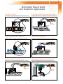
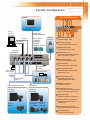
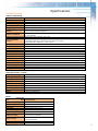
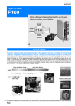
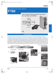
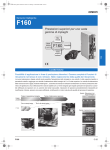
Solve it with the problem solvers.
High-Speed Processing and Advanced
Performance Solve Today’s Demanding
Vision Applications
Demanding vision applications require multiple complex
inspections with high-speed analysis to maintain top quality in
the finished product. Omron meets this need with the F250 vision
sensor. It uses up to four cameras on a single controller to
deliver high-speed results for ultra-complex inspections. In fact,
F250 is the world’s first multi-camera vision sensor to perform a
high-speed, real-time rotation search for parts or features located
at random angles and positions. On a conveyor line for example,
other vision systems require slowed conveyor speeds to allow
complex inspections, potentially creating a bottleneck in
production. With the F250’s real-time rotation search, production
speeds are maintained.
World's First* Real-time Rotation Search
360° Rotation Compensation Speed (in field image mode)
Conventional
OMRON
products
F250
Here’s how Omron’s technology and know-how give you the
productivity edge:
• Edge Code Technology adds enhanced and ultra-precise
detection performance to many of the F250’s commonly used
algorithms. For example, with Edge Code Technology,
positioning can be done with high precision and defect
inspection can detect fine scratches, dirt and deformities.
• Omron’s original QUEST Optical Character Recognition and
Verification algorithm enhances the detection of printed
alphanumeric characters regardless of their shape or size with
no need to teach the F250 any characters. The QUEST OCR/OCV
algorithm uses built-in character libraries to discern multiple
characters simultaneously.
100 ms
8.3 ms
12 times faster
Advanced Algorithms
Edge Code (EC) Positioning
High-precision positioning and
low-contrast workpiece detection
*Based on OMRON test results of
1 August 2001.
Fast Image Input
Conventional
OMRON
products
33.3 ms
16.7 ms
Conventional
OMRON
products
F250
Frame image input
Field image input
F250
16.7 ms
QUEST Character Recognition
Confirm expiration dates
and lot numbers using the
OCR/OCV algorithm
8.3 ms
Edge Code (EC) Defect Inspection
Inspection for fine scratches, dirt,
and deformation
Fast Image Processing
Conventional
OMRON
products
2 to 10 times
F250
2
Fine Matching
Inspection of characters and
graphic patterns for blurring or dirt
High-Speed Measurement
and Inspection Applications
Product Sorting
Pharmaceutical Package Inspection
Sort boxes by size or labels, inspect seams, and verify lot codes.
Pill presence/absence and Lot/Date code confirmation on blister packs.
F250 Controller
F250 Controller
Ethernet
Character Data
Trigger sensor
ACME
BOX
ACME
BOX
ACME
BOX
Trigger sensor
High-Speed Bottle Inspection
Electronics Inspection
Inspect for defects, dimensions, conformance and date code.
Electronic component presence/absence and position inspection.
F250 Controller
F250 Controller
Trigger sensor
Trigger sensor
Random Position Reference
High-Speed Robotic Tool Guidance
Report random, odd-shaped package positioning on a conveyor.
Report tool and part alignment and tool wear positioning to robot.
S.C.A.R.A. Robot
F250 Controller
F250 Controller
Ethernet
Part Position Data
Ethernet
Position and
Tooling Data
Trigger sensor
Tooling
3
Advanced Algorithms
Edge Code (EC) Technology
Edge Code Technology’s advanced inspection and positioning algorithms use the direction of changes in
brightness and the differences in image brightness to achieve ultra-precise detection. EC technology also enables
the detection of low-contrast images and deformed or partly defective parts or features to a degree that was never
before possible.
EC Positioning
The F250 performs positioning and measurement accurately even if the workpiece
internally changes or its appearance viewed from the sensor changes.
Positioning of PCB’s Fiducial Marks
Low-contrast
Rotation
Internal dirt
EC Defect Inspection
Detects scratches on metal surfaces, even with low-contrast images.
Accurately detects fine defects that
could not be detected before, even
on edges of parts.
4
Correctly detects distortion or
deformation in rubber packing, etc.
Detects scratches on metal
surfaces, even with low-contrast
images.
Advanced Algorithms
QUEST Optical Character Recognition
QUEST technology can recognize characters correctly regardless of their size or shape. Using built-in character libraries
makes setup easy with no character teaching required.
Correctly Recognizes Six Different Types of Character Variations
Size
2
Width
Breaks
2
2
2
2
2
2
Blurriness
Line width
Printed characters such as
expiration dates, lot numbers
and date codes can vary in
shape, size and line width based
on the printing method and
conditions. The QUEST algorithm
ensures that the six most
common types of variations are
always recognized correctly.
Inclination
QUEST technology has built-in
character libraries of commonly
used factory automation fonts
stored for ready reference. This
eliminates the need to register
characters as models, or teach
and create font or character
libraries to handle most text.
Setup time during installation is
greatly reduced.
No Need to Register Characters in a Library
Fine Matching
The F250 quickly and accurately detects any differences between the registered model and the image being measured. This dramatically
improved model matching algorithm now reveals fine defects on the edges of characters, printed labels and graphic patterns that may have
gone undetected in the past using less accurate matching algorithms.
Application example: inspection for soft drink bottle caps
Displays inspection
results as an area value
Registered image
Cracks near
the edge
Fine
Matching
Fine stains
Stains in
patterns
Incomplete characters
Inspected image
5
Reach Full Productivity Quickly
Omron’s F250 boosts productivity in every process from installation and setup to maintenance and adjustments
with maximum flexibility and usability. An on-screen menu system allows applications to be created using a
simple tool insertion method. The application program is then displayed sequentially, in the order of execution.
An I/O monitor screen allows easy monitoring of the controller’s inputs and outputs for faster setup and
troubleshooting. The line brightness meter can be used to show the pixel density (brightness) of any single line
of pixels in both horizontal and vertical directions, making setup and troubleshooting for measurements an
easier task. The F250 also uses a removable Flash-RAM memory card for storage and backup of controller
settings and measurement images.
Trend Monitor Function
Use the Trend Monitor to view measurement
values and judgment results. They can be
trended and displayed on the monitor while in
operation, allowing easy monitoring of the
application during setup, online operation or
troubleshooting. The NG Image Save function
can be useful for solving the cause of rejects by
providing visual confirmation with the NG image
when they occur. The Judgment Results Limits
can also be adjusted while watching the trend
monitor, simplifying setup and adjustment.
Viewing the History of
Measurement Values
on the Trend Monitor
Switching
Displays
Confirming
Defects from
Past NG
Images
Simple, Flexible Configuration Using the Application Software
Easy setup process:
1. Select the necessary inspection
functions from the application
software and install them
F250-UME Application Software
EC Position
QUEST OCV
2. Any combination of inspection
functions can be selected from
the menu.
F250-UME
Fine Matching
*Branch processing also possible using
measurement results and external input.
Trend Monitor
Processing Item Functions
The F250-UME Application Software can be used to install the following measurement items and perform combinations of inspections.
Position Compensation
General Measurement
Binary position compensation
EC position compensation
Edge position compensation
Model position compensation
Circle position compensation
Reset scroll
Scroll
Detecting binary defects
Classification
Density defects
EC defect
EC positioning
Edge position
Fine matching
EC circle count
Pattern
Results Output
Memory card data output
DO data output
DO judgement output
Host link data output
Normal data output
6
QUEST character
verification
Rotation positioning
ECM search
Lot number OCV 1
Labeling
Label data
Edge pitch
Density data
Measurement Support Branch Control
Calculation
Elapsed time
Get unit data
Wait
Set unit data
Trend monitor
Conditional branch
DI branch
End
Results Display
String display
Measurement display
Judgement display
Item display
Time display
Figure display
Line display
Box display
Circle display
Cursor display
System Configuration
Monitor
F250-C50/C55 Controller
10
11
12 13
8
7
6
Color LCD Monitor
F150-M05L
PLC or
Personal
Computer
Monitor Cable
RCA/BNC Video Cable
Ethernet
RS-232C/422
Memory Cards
F160-N64S
(64 Mbytes)
F250-UME
Application Software
64M
5
Console
F160-KP
F250-UME
Controller
F250-C50/C55
14
9
4
1 2 3
1 POWER Indicator (Green)
Lit while the power is ON.
2 RUN Indicator (Orange)
Lit while the F250 is in Run Mode.
3 ERROR Indicator (Red)
Lit when an error has occurred.
4 I/O Connectors 0 and 1
Connects the F250 to external devices
such as sync sensors or PLCs.
5 Power Supply Terminal
Connects to the DC power supply.
Parallel Cable
F160-VP
Power Supply
Synchronous Sensor
Recommended
model:
OMRON
S8TS
Programmable Controller
Camera Cable
F150-VS
F160 Double-Speed Cameras
Cameras with Intelligent Lighting
F160-SLC20
F160-SLC50
F150 Cameras
Cameras with Intelligent Lighting
F150-SLC20
F150-SLC50
6 Console Connector
Connects the F250 to a user keypad.
7 Memory Card LEDs 0 and 1
Lit when the Memory Card is being
supplied with power.
8 Memory Card Slots 0 and 1
Holds Memory Cards or card
containing Application Software.
9 CAMERA 0-3 Connectors
Connects to Cameras.
10 RS-232C/422A Connector
Connects the F250 to an external device
such as a personal computer or PLC.
11 Ethernet Connector
Connects to a personal computer, etc.
Camera
F160-S1
Cameras with Light Source
Camera
F150-SL20A
F150-S1A
F150-SL50A
*The F300-S2R, F300-S3DR, and F300-S Cameras are also compatible
12 Monitor Connector (S-VIDEO Output)
Connects to the Monitor with an
S-VIDEO input.
13 Monitor Connector (Composite
Video Output) Connects to the Monitor.
14 Grounding Terminal
Connects to the ground wire.
7
Dimensions
Unit: mm (inches)
Controller
Console
F250-C50/C55
F160-KP
29.7 (1.17)
20
(0.79)
115 min.
(4.53)
270 (10.63)
48 (1.89)
73 (2.87)
SHIFT
ENT
TRIG
8
(0.31)
ESC
F1
135.5 (5.33)
[25]
(0.98)
197 (7.76)
220±0.6 (8.66)
137±0.5 (5.39)
Four M4 (mounting screws)*
[13]
(0.51)
190±0.6 (7.48)
F6
F5
F7
F9
F8
Stopper
10 to 13
(0.39 to 0.51)
Plate thickness: T
[40]
(1.57)
F3
F2
F4
12 dia.
40 (1.57)
2000 (78.74)
*Screw length: L(10 + T<L<13 + T)
Liquid Crystal Monitor
Double-Speed Camera
F150-M05L
Mounting plate thickness: 1.6 (0.63) to 4.8 (0.19)
F160-SLC20
143 (5.63)
[46 max.]
85 (3.35)*
2.5
12
100 (3.94)
185 (7.28)
5.5 (0.22)
42.2
(1.66)
12
31
40 (1.57)
25
(0.98)
4 dia.
42.5
70 (2.76)
10
(0.39)
Mounting bracket
30.5
(1.20)
96.25 (3.79)
145 (5.71)
155 (6.10)
46.5 (1.83)
50min
2.5
73 (2.87)
SYNC
132 (5.20)
POWER
70 (2.76)
12
12
F150-VM Monitor Cable
• Tolerance: ±1 mm
174 (6.85)
8 (0.32)
• The dimensions in brackets are reference values.
23.25±1.3 (0.92)
1/4-20UNC with depth of 10 mm
Two M4 mounting holes with depth of 10 mm
86.25 (3.40)
Panel cutout dimensions
13.25±1.1 (0.52)
20±1.3 (0.79)
133.5 +0.5mm
0
(5.26)
F160-SLC50
80 (3.15)
46.5 (1.83)
85 (3.35)*
4 dia.
F160-S1
16
103.25 (4.06)
8 (0.32)
30.5
(1.20)
23.25±1.3
15.5
(0.61)
54.5 (2.15)
46.5 (1.83)
8
6 (0.24)
1/4-20UNC with depth of 10 mm
1"-32UN-2A
(C mount)
Two M4 mounting holes
with depth of 10 mm
93.25 (3.67)
8
30.5 (1.20)
31.25±2 (1.24)
21.25±2
6.2
(0.24)
6.2
(0.24)
Light connector
(8.8 dia.)
(30.7)
31
60 (2.36)
25
(0.98)
11 29 (1.14)
16
52.5 (2.07)
2.5
90 (3.54)
10
(0.39)
21.7 (0.85)
16
14.5
(0.57)
90 (3.54)
16
2.5
175.5 +0.5mm
0
(6.91)
31 (1.22)
Camera cable connector
(11.8 dia.)
Two M4 mounting holes with depth of 8 mm
13.25±1.1 (0.52)
20±1.3 (0.79)
1/4-20UNC with depth of 8 mm
20±1.3 (0.79)
Note: Dimensions for F150 cameras are in Omron’s F150-3 Vision Sensor brochure SB F1503-1.
8
Specifications
Rating/Function
Controller: F250-C50/C55
Item
Specifications
Connectable cameras
F150-S1A/SL20/SL50/SLC20/SLC50, F160-S1/SLC20/SLC50, F300-S2R/S3DR/S
4
Number of cameras connectable
Number of pixels
512 x 484 (H x V)
Number of scenes
32 (Expansion possible using Memory Cards)
Image storage function
Maximum of 35 images stored
Filtering
Smoothing (strong, weak), edge enhancement, edge extraction (horizontal, vertical, both), dilation,
erosion, median, background suppression
Installing measurement items using application software, and combining and setting measurement items
by menu operations
Operation customization functions Menu masking, password setting, shortcut keys
Display items: Character strings (measurement values, judgement results, times, user-specified characters,
Screen customization
measurement region names), figures (lines, boxes, circles, cross cursors)
functions
Specified parameters: Display color, position, and size
Operations and settings
Trend monitor function
Supported
Memory card slots
2
Monitor interface
Composite video output: 1 channel, S-VIDEO output: 1 channel
Ethernet
10Base-T: 1 channel
Serial communications
RS-232C/422A: 1 channel
Parallel I/O
21 inputs and 46 outputs
Strobe interface
4 channels (included in parallel outputs)
Power supply voltage
20.4 to 26.4 VDC
Current consumption
Approx. 3.7 A (when four F160-SLC50 Cameras connected)
Ambient temperature
Operating: 0 to 50°C, Storage: -25 to +65°C (with no icing or condensation)
Ambient humidity
Operating and storage: 35% to 85% (with no condensation)
External dimensions
270 x 81 x 197 mm (W x H x D)
Weight
Approx. 2.7 kg (Controller only)
Double-Speed Camera : F160-S1
Picture element
1/3” Interline CCD
Effective pixels
659 x 494 (H x V)
Scanning method
1/60-s non-interlace (frame) mode, 1/120-s 2:1 interlace (field) mode
Shutter
Electronic shutter: select from 8 shutter-speed settings (1/120 to 1/20,000 s) using menu.
Camera with Intelligent Lighting F160-SLC20 (field of vision: 20 mm), F160-SLC50 (field of vision: 50 mm)
Ambient temperature
Operating: 0 to 50°C, Storage: -25 to +60°C
Ambient humidity
Operating and storage: 35% to 85% (with no condensation)
External dimensions
31 x 40 x 54.5 (W x H x D) mm (not including connectors and other protruding parts)
Weight
Approx. 85 g (Camera only)
Note: Specifications for F150 cameras are in Omron’s F150-3 Vision Sensor brochure SB F1503-1.
Monitor
Item
Model number
Name
Size
F150-M05L
Color LCD Monitor
5.5 inches
Type
Liquid crystal color TFT
Resolution
Input signals
320 x 240 dots
NTSC composite video (1.0 V/75 Ω)
Power supply voltage
20.4 to 26.4 VDC
Current consumption
Approx. 700 mA
Operating: 0 to 50°C; Storage: -25 to 65°C
(with no icing or condensation)
Ambient temperature
Weight (monitor only)
Operating or storage: 35% to 85%
(with no condensation)
Approx. 1 kg
Accessories
Instruction manual and 4 mounting brackets
Ambient humidity
9
F250 Vision Sensor Selection Guide
First:
Start by selecting the controller part number with the correct input/output type, NPN or PNP, to meet
the applications needs.
Second:
Choose cameras for the system. Omron offers three F160 double-speed or five standard speed F150
cameras. Select one to four cameras based on the application. Cameras with built-in Intelligent Light
Source are available for 20- or 50-mm fields of vision in both the F150 and F160 series. If a different field
of vision and lighting is required, use the F150-S1A or F160-S1 camera without lens and light source.
Important: cameras from the F150, F160 and F300 series CAN NOT be mixed on a single controller.
Note: F150 camera distance setting information is in vision sensor brochure SB F1503-1; F160 camera
distance setting information is in brochure SB F160-1.
Third:
Choose camera cables, Parallel I/O cable, monitor and monitor cable as required. For additional camera
cable and parallel I/O cable lengths and monitor options, please consult your Omron vision
representative.
Fourth:
Select lenses and lighting for the application if F150-S1A or F160-S1 cameras are used. Refer to the Lens
Selection Guide (next page). The intelligent lighting interface is available for F150-S1A and F160-S1
cameras to allow the use of controllable external lighting options. Please refer to the back cover of this
brochure for additional intelligent lighting information and consult your Omron vision representative for
assistance in selecting lenses and lighting.
+
+
+
+
Ordering Information
Name
Model number
Controllers F250-C50
F250-C55
Comments
NPN input/output
PNP input/output
Double-speed cameras
with intelligent F160-SLC20
lighting F160-SLC50
Camera only F160-S1
20 mm field of view
50 mm field of view
Without lens or light source
Compatible F150 cameras
with intelligent F150-SLC20
lighting F150-SLC50
with light F150-SL20
F150-SL50
Camera only F150-S1A
Console F160-KP
Color LCD monitor F150-M05L
Memory card F160-N64S
Application software F250-UME
Camera cable F150-VS
Monitor cable RCA/BNC Video Cable
Parallel cable F160-VP
Extension tubes F150-EXT
10
20 mm field of view
50 mm field of view
20 mm field of view, red LED light source
50 mm field of view, red LED light source
Without lens or light source
Keypad with shortcut buttons
5.5 inch color LCD
Memory capacity: 64 Mbytes
For F160 (double-speed) & F150 cameras; cable length: 3 m
Cable length: 2 m
Loose-wire cable for parallel I/O connectors; cable length: 2 m
A set of six extension tubes that are 40, 20, 10, 5, 1, and 0.5 mm
in length respectively
Lens Selection Guide
First:
Start by defining the field of view requirements for each camera. Refer to the diagram at bottom left.
The field of view is considered to be the area or areas requiring inspection. This does not necessarily
include the entire part or object in the field of view.
Second:
Determine the camera distance, measured from the object surface to the camera. Refer to the lens setting illustration for
additional information about setting distance. This distance can impose limitations on the field of view and lens choice.
To get the greatest flexibility in lens selection, keep the camera setting distance as flexible as possible.
Third:
Using the field of view and camera setting distance requirements, use the optical graph axis marked "Field of view L (mm)"
to find the matching field of view size. Use the optical graph axis marked "Camera distance A (mm)" to find the approximate
camera setting distance. Follow the values across the chart until they cross. Refer to the lens part reference on the right at
the end of the graph line to find the correct lens size. (If a "t" value other than 0 is indicated, corresponding lens extension
tubes will need to be added in between the camera and lens in order to properly focus the image. The "t" value indicates the
thickness of the extension tubes required.)
Note: Extension tube length should not exceed 10% of the focal length of the lens. When looking at other manufacturers’
lenses not referenced by Omron, please use a 1/3-inch CCD size as a selection value reference.
Fourth:
If an appropriate lens cannot be found to satisfy your application, please consult your Omron vision representative for
additional assistance in lens selection options.
CCTV Lens
Model
Dimensions
Focal length
Brightness
F150-L8
29 dia. x 34.5 L*
8.0 mm
F1.3
F150-L12
30 dia. x 34.5 L*
12.5 mm
F1.4
F150-L16
30 dia. x 24.5 L*
16.0 mm
F1.4
F150-L25
30 dia. x 24.5 L*
25.0 mm
F1.4
F150-L50
32 dia. x 37 L*
50.0 mm
F1.8
F150-L75
32 dia. x 42.5 L*
75.0 mm
F2.7
* Lens diameter does not include lens ring lock screw height.
Note: Omron reserves the right to change lens suppliers and specifications without notification. Please verify all lenses with sales personnel.
Lens model: F150-________
Optical Graph
L75
L50
Camera distance A (mm)
Unit: mm
5,000
L25
Max.
outer
dia.
1"-32UN 30 dia.
-2A
3,000
L16
L12
2,000
Total length
L8
1,000
500
Camera
300
Extension Tube
200
Lens
t: Extension Tube thickness
100
Camera distance
A (mm)
50
4
5
10
20
30
50
100
200
300
500
Field of view L (mm)
Field of vision
L (mm)
Note: All values are approximate values. It is recommended that the camera distance
be adjusted by sliding the camera forward or backward in actual operation.
11
The Right Lights & Camera
For Your Action
Omron’s compact shutter camera is perfect for high-speed inspection applications
and can be fitted with several different light sources, including those that support
the Intelligent Light Source specification, depending on the application.
Unique, Intelligent Light Sources (ILS)
Omron’s ILSs and ILS integrated cameras are designed to enhance and simplify your vision
applications. The ILSs use a hood shape that reduces external interference, making conditions ideal
for highly accurate inspections. The combination of red and green LEDs also enables the F250 to
inspect a wide range of objects. One ILS version offers the ability of adjustable coaxial vertical
lighting in addition to the adjustable ring light. The adjustable ring light lets the user adjust
brightness and light direction based on the application requirements.
Maximize Lighting Control
With an Intelligent Light Source camera, the F250’s controller menus
take all of the guesswork out of proper lighting. Operators can
control the illuminated area and light intensity from the controller
menus. The settings are easily changed without direct adjustment to
the light source. Lighting positioning is stored with other scene data
so operators can change the lighting conditions to match different
operating environments. Because the settings are numeric data, it is
possible to recreate the lighting conditions from machine to machine.
Solve Machine Vision Lighting Problems with
Easy-to-Use Intelligent Lighting Control
A Visionary Partnership
Omron and CCS America have partnered to provide the CCS
Intelligent Lighting Adapter (ILA), lighting power supplies and
wide range of controllable LED lighting for Omron’s F-series
Vision Sensors. Features include:
• 64 light level steps per light
• Up to 4 controllable lights per camera and power supply
• Set light intensity and angle in controller software
• Settings are saved and repeatable
• Compatible with Omron F150-3, F160 and F250 vision sensors
• Over 200 CCS lighting options to choose from; consult your
Omron vision representative for additional information and
assistance regarding CCS lighting products
UNITED STATES REGIONAL SALES OFFICES
800.55.OMRON or 847-843-7900
www.omron.com/oei
OMRON ELECTRONICS LLC
Technical Automation Solution Division
Schaumburg, IL
OMRON CANADA, INC.
Scarborough, Ontario
SB F250-1 2/02/10M
© 2002 OMRON ELECTRONICS LLC
Printed in the U.S.A.
CANADA REGIONAL SALES OFFICES
416.286.6465
BRAZIL SALES OFFICE
55.11.5564.6488
MEXICO SALES OFFICE - FLORIDA
954.227.2121
MEXICO SALES OFFICES - MEXICO
Mexico D.F. 555.534.1195 Monterrey, N.L. 818.377.4281
ARGENTINA SALES OFFICE - CONO SUR
54.114.787.1129
AUTHORIZED DISTRIBUTOR:
Mouser Electronics
Authorized Distributor
Click to View Pricing, Inventory, Delivery & Lifecycle Information:
Omron:
F250-C55 F250-C50