1
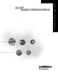
Installation and Maintenance Manual
Technical Manual - Volume I
DX-120 Installation and Maintenance Manual
Technical Manual - Volume I
Copyright © January, 2007 Vertical Communications, Inc.
All rights reserved. Unauthorized use of this document is prohibited.
Vertical Communications, Inc.
106 Cattlemen Road, Sarasota, FL 34243
(941)554-5000 or (800) 266-3425
-NoticeVertical Communications, the Vertical Communications logo and combinations thereof,
and Corporate Office are trademarks ofVertical Communications, Inc. Artisoft, TeleVantage, InstantOffice,
Comdial and Vertical Networks are registered trademarks of Artisoft, Inc.
All other brand and product names are used for identification only
and are the property of their respective holders.
.
DISCLAIMER
This manual has been developed by Vertical Communications, Inc. (the “Company”) and
is intended for the use of its customers, potential customers, and service personnel. The
information in this manual is subject to change without notice. While every effort has been
made to eliminate errors, the Company disclaims liability for any difficulties arising from
the interpretation of the information contained herein.
The information contained herein does not purport to cover all details or variations in
equipment or to provide for every possible contingency to be met in connection with installation, operation, or maintenance. Should further information be desired, or should particular problems arise which are not covered sufficiently for the purchaser’s purposes,
contact Vertical Communications, Inc.
DX-120 Installation and Maintenance Manual
TABLE OF CONTENTS
SAFETY AND REGULATORY CONSIDERATIONS
SAFETY . . . . . . . . . . . . . . . . . . . . . . . . . . . . . . . . . . . . . . . . . . . . . . . . . . . . . . . . . . . . . . . . . . . .1
Protecting Against Static Electricity . . . . . . . . . . . . . . . . . . . . . . . . . . . . . . . . . . . . . . . . . . . . . . . . . 1
REGULATIONS . . . . . . . . . . . . . . . . . . . . . . . . . . . . . . . . . . . . . . . . . . . . . . . . . . . . . . . . . . . . . . .2
Complying with Underwriters Laboratories Regulations . . . . . . . . . . . . . . . . . . . . . . . . . . . . . . . . . 2
FCC and Industry Canada (IC) Rules and Regulations . . . . . . . . . . . . . . . . . . . . . . . . . . . . . . . . . 2
SECTION 1 - INTRODUCTION
USING THIS MANUAL . . . . . . . . . . . . . . . . . . . . . . . . . . . . . . . . . . . . . . . . . . . . . . . . . . . . . . . . . .7
Locating Documentation . . . . . . . . . . . . . . . . . . . . . . . . . . . . . . . . . . . . . . . . . . . . . . . . . . . . . . . . . 8
OVERVIEW . . . . . . . . . . . . . . . . . . . . . . . . . . . . . . . . . . . . . . . . . . . . . . . . . . . . . . . . . . . . . . . . . .9
System Technology . . . . . . . . . . . . . . . . . . . . . . . . . . . . . . . . . . . . . . . . . . . . . . . . . . . . . . . . . . . . . 9
Configuration . . . . . . . . . . . . . . . . . . . . . . . . . . . . . . . . . . . . . . . . . . . . . . . . . . . . . . . . . . . . . . . . . 11
Key Service Unit. . . . . . . . . . . . . . . . . . . . . . . . . . . . . . . . . . . . . . . . . . . . . . . . . . . . . . . . . . . . . . . 15
Power Supply . . . . . . . . . . . . . . . . . . . . . . . . . . . . . . . . . . . . . . . . . . . . . . . . . . . . . . . . . . . . . . . . . 16
CPM (Central Processor Module) . . . . . . . . . . . . . . . . . . . . . . . . . . . . . . . . . . . . . . . . . . . . . . . . . 17
408M (KSU1 Component) . . . . . . . . . . . . . . . . . . . . . . . . . . . . . . . . . . . . . . . . . . . . . . . . . . . . . . . 18
408E (KSU II Component) . . . . . . . . . . . . . . . . . . . . . . . . . . . . . . . . . . . . . . . . . . . . . . . . . . . . . . . 19
APM4 (Analog Port Module - 4 Circuits) . . . . . . . . . . . . . . . . . . . . . . . . . . . . . . . . . . . . . . . . . . . . 20
DPM8 (Digital Port Module - 8 Circuits) . . . . . . . . . . . . . . . . . . . . . . . . . . . . . . . . . . . . . . . . . . . . . 21
DPM16 (Digital Port Module - 16 Circuits) . . . . . . . . . . . . . . . . . . . . . . . . . . . . . . . . . . . . . . . . . . . 22
COM4 (Central Office Module - 4 Circuits) . . . . . . . . . . . . . . . . . . . . . . . . . . . . . . . . . . . . . . . . . . 23
MDM (Modem Module) . . . . . . . . . . . . . . . . . . . . . . . . . . . . . . . . . . . . . . . . . . . . . . . . . . . . . . . . . 24
AAM (Automated Attendant Module) . . . . . . . . . . . . . . . . . . . . . . . . . . . . . . . . . . . . . . . . . . . . . . . 25
T1 Card (T1 Module) Details . . . . . . . . . . . . . . . . . . . . . . . . . . . . . . . . . . . . . . . . . . . . . . . . . . . . . 26
ISDN Card (T1/PRI Module) Details . . . . . . . . . . . . . . . . . . . . . . . . . . . . . . . . . . . . . . . . . . . . . . . 27
DET (Digital Executive Telephone) . . . . . . . . . . . . . . . . . . . . . . . . . . . . . . . . . . . . . . . . . . . . . . . . 29
DSS (Direct Station Selection) Console. . . . . . . . . . . . . . . . . . . . . . . . . . . . . . . . . . . . . . . . . . . . . 30
Specifications . . . . . . . . . . . . . . . . . . . . . . . . . . . . . . . . . . . . . . . . . . . . . . . . . . . . . . . . . . . . . . . . . 31
Table of Contents (continued on next page)
-1-
TABLE OF CONTENTS
DX-120 Installation and Maintenance Manual
Table of Contents (continued)
SECTION 2 - INSTALLATION
INSTALLING THE DX-120 . . . . . . . . . . . . . . . . . . . . . . . . . . . . . . . . . . . . . . . . . . . . . . . . . . . . . . . 41
Installation Overview . . . . . . . . . . . . . . . . . . . . . . . . . . . . . . . . . . . . . . . . . . . . . . . . . . . . . . . . . . .
Site Planning . . . . . . . . . . . . . . . . . . . . . . . . . . . . . . . . . . . . . . . . . . . . . . . . . . . . . . . . . . . . . . . . .
Tools and Supplies. . . . . . . . . . . . . . . . . . . . . . . . . . . . . . . . . . . . . . . . . . . . . . . . . . . . . . . . . . . . .
Preparing the Main Distribution Frame . . . . . . . . . . . . . . . . . . . . . . . . . . . . . . . . . . . . . . . . . . . . .
KSU Wiring . . . . . . . . . . . . . . . . . . . . . . . . . . . . . . . . . . . . . . . . . . . . . . . . . . . . . . . . . . . . . . . . . .
Typical MDF Installation . . . . . . . . . . . . . . . . . . . . . . . . . . . . . . . . . . . . . . . . . . . . . . . . . . . . . . . .
KSU Components . . . . . . . . . . . . . . . . . . . . . . . . . . . . . . . . . . . . . . . . . . . . . . . . . . . . . . . . . . . . .
Adding an APM4 . . . . . . . . . . . . . . . . . . . . . . . . . . . . . . . . . . . . . . . . . . . . . . . . . . . . . . . . . . . . . .
Adding a COM4 . . . . . . . . . . . . . . . . . . . . . . . . . . . . . . . . . . . . . . . . . . . . . . . . . . . . . . . . . . . . . . .
Adding an MDM . . . . . . . . . . . . . . . . . . . . . . . . . . . . . . . . . . . . . . . . . . . . . . . . . . . . . . . . . . . . . . .
Adding an AAM . . . . . . . . . . . . . . . . . . . . . . . . . . . . . . . . . . . . . . . . . . . . . . . . . . . . . . . . . . . . . . .
Adding a KSU2 Second Cabinet . . . . . . . . . . . . . . . . . . . . . . . . . . . . . . . . . . . . . . . . . . . . . . . . . .
Adding a Music Source . . . . . . . . . . . . . . . . . . . . . . . . . . . . . . . . . . . . . . . . . . . . . . . . . . . . . . . . .
Adding an External Pager . . . . . . . . . . . . . . . . . . . . . . . . . . . . . . . . . . . . . . . . . . . . . . . . . . . . . . .
Add a Loud Bell Control or Gate Control . . . . . . . . . . . . . . . . . . . . . . . . . . . . . . . . . . . . . . . . . . . .
Adding a DPM16 (Digital Port Module – 16 port) . . . . . . . . . . . . . . . . . . . . . . . . . . . . . . . . . . . . . .
Adding a T1 or ISDN (T1/PRI) Card. . . . . . . . . . . . . . . . . . . . . . . . . . . . . . . . . . . . . . . . . . . . . . . .
Connecting a Serial Cable for PC-DBA . . . . . . . . . . . . . . . . . . . . . . . . . . . . . . . . . . . . . . . . . . . . .
Connecting a Serial Cable for SMDR. . . . . . . . . . . . . . . . . . . . . . . . . . . . . . . . . . . . . . . . . . . . . . .
Power-up Initialization (Cold Start). . . . . . . . . . . . . . . . . . . . . . . . . . . . . . . . . . . . . . . . . . . . . . . . .
41
42
43
43
46
48
49
54
56
58
60
61
63
65
66
68
69
70
71
72
SECTION 3 - MAINTENANCE & TROUBLESHOOTING
SYSTEM MAINTENANCE . . . . . . . . . . . . . . . . . . . . . . . . . . . . . . . . . . . . . . . . . . . . . . . . . . . . . . . .75
Cleaning the Telephones . . . . . . . . . . . . . . . . . . . . . . . . . . . . . . . . . . . . . . . . . . . . . . . . . . . . . . . 75
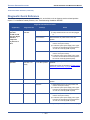
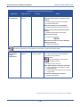
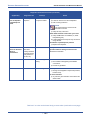
TECHNICAL PROBLEM SOLUTIONS . . . . . . . . . . . . . . . . . . . . . . . . . . . . . . . . . . . . . . . . . . . . . . . 75
Problems Not Related to System Issues . . . . . . . . . . . . . . . . . . . . . . . . . . . . . . . . . . . . . . . . . . . . 75
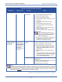
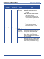
Diagnostic Quick Reference. . . . . . . . . . . . . . . . . . . . . . . . . . . . . . . . . . . . . . . . . . . . . . . . . . . . . . 76
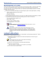
MAINTENANCE UTILITIES . . . . . . . . . . . . . . . . . . . . . . . . . . . . . . . . . . . . . . . . . . . . . . . . . . . . . . . 82
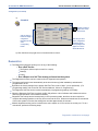
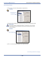
Loading PC-DBA software . . . . . . . . . . . . . . . . . . . . . . . . . . . . . . . . . . . . . . . . . . . . . . . . . . . . . . . 82
CONNECTING TO THE SYSTEM . . . . . . . . . . . . . . . . . . . . . . . . . . . . . . . . . . . . . . . . . . . . . . . . . . . 83
Cable Connection. . . . . . . . . . . . . . . . . . . . . . . . . . . . . . . . . . . . . . . . . . . . . . . . . . . . . . . . . . . . . . 83
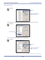
Connecting PC-DBA to the DX-120 Switch . . . . . . . . . . . . . . . . . . . . . . . . . . . . . . . . . . . . . . . . . . 84
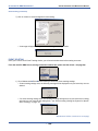
Establishing a Modem Connection with PC-DBA. . . . . . . . . . . . . . . . . . . . . . . . . . . . . . . . . . . . . . 86
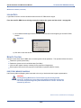
ACCESSING PC-DBA MAINTENANCE . . . . . . . . . . . . . . . . . . . . . . . . . . . . . . . . . . . . . . . . . . . . . . 88
Maintenance Utilities (Menu Items) . . . . . . . . . . . . . . . . . . . . . . . . . . . . . . . . . . . . . . . . . . . . . . . . 89
Table of Contents (continued on next page)
-2-
TABLE OF CONTENTS
DX-120 Installation and Maintenance Manual
Table of Contents (continued)
SECTION 4 - INSTALLATION ISSUES
TROUBLESHOOTING INSTALLATION ISSUES . . . . . . . . . . . . . . . . . . . . . . . . . . . . . . . . . . . . . . . 113
Corrupted Database on Initial System Setup . . . . . . . . . . . . . . . . . . . . . . . . . . . . . . . . . . . . . . . .
Adding Hardware to an Existing System . . . . . . . . . . . . . . . . . . . . . . . . . . . . . . . . . . . . . . . . . . .
Voice Mail Doesn’t Work (“No Legal Member” Error). . . . . . . . . . . . . . . . . . . . . . . . . . . . . . . . . .
Invalid Entries Calling a Busy Station (Issues with Multiple Mailbox Greetings) . . . . . . . . . . . . .
Ensuring Optimum Call Handling Performance . . . . . . . . . . . . . . . . . . . . . . . . . . . . . . . . . . . . . .
Ringing a Group Of Phones
Before Routing the Call to Auto-Attendant. . . . . . . . . . . . . . . . . . . . . . . . . . . . . . . . . . . . . . . . .
Using Multiple Lines &
Assigning Different Auto-Attendant Greetings for Each Line . . . . . . . . . . . . . . . . . . . . . . . . . . .
Setting Up Message Delivery to a Cell Phone . . . . . . . . . . . . . . . . . . . . . . . . . . . . . . . . . . . . . . .
Using Prime CO Instead of Intercom with Modem or Fax . . . . . . . . . . . . . . . . . . . . . . . . . . . . . .
Digits Passed Inband to the Voice Mail in an Overflow 1 Condition . . . . . . . . . . . . . . . . . . . . . .
Digits Passed Inband to the Voice Mail in an Overflow 2 Condition . . . . . . . . . . . . . . . . . . . . . .
Digits Passed Inband to the Voice Mail in a Re-Route Condition . . . . . . . . . . . . . . . . . . . . . . . .
113
113
114
117
118
119
122
125
127
129
130
131
INDEX
INDEX . . . . . . . . . . . . . . . . . . . . . . . . . . . . . . . . . . . . . . . . . . . . . . . . . . . . . . . . . . . . . . . . . . . . 133
-3-
THIS PAGE INTENTIONALLY LEFT BLANK
DX-120 Installation Manual - Technical Manual Vol I
SAFETY AND REGULATORY CONSIDERATIONS
SAFETY
Protecting Against Static Electricity
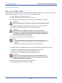
CAUTION
Circuit boards are susceptible to damage caused by electrostatic discharge. You
must keep this in mind as you handle the circuit boards. Refer to Vertical
publication IMI01-005, Handling of Electrostatically Sensitive Components, for
general information. Specific handling precautions are also included in this
installation manual.
The telephone system may include some installed circuit boards when it arrives at your site. The equipment
cabinets provides universal slots that will accept either line or station boards.
When removing or installing circuit boards in the cabinets, you must wear a static discharge wrist strap. Be sure
that the strap is touching bare skin and is connected to an AC or earth ground.
Disconnect the AC power cord from the AC outlet (or extenral battery back-up system if applicable) before you
remove or install the circuit board.Whenever you remove a circuit board from a cabinet, immediately place the
board in a static protection bag while you still have your wrist strap in place and properly grounded.
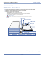
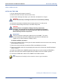
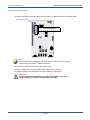
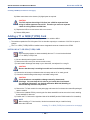
When removing circuit boards from an installation location for servicing, always transport them to a static-safe
work area in static protection bags. If you do not already have a static-safe work area, you can create one by
arranging a work area as detailed in the illustration.
Common Point Ground
Static Wrist Strap
ESD Protective Mat
ESD Protective
Work surface
Typical Earth Ground
ESD Protective Mat
- 1-
REGULATIONS
DX-120 Installation Manual - Technical Manual Vol I
REGULATIONS
Complying with Underwriters Laboratories Regulations
Per the Underwriters Laboratories regulation 1950, be aware of the following precautions when installing telephone
equipment that is to be directly connected to the telephone company network:
• Never install telephone wiring during a lightning storm
• Never install telephone jacks in wet locations unless the jack is specifically designed for wet locations
• Never touch uninsulated telephone wires or terminals unless the telephone line has been disconnected at the
network interface
• Use caution when installing or modifying telephone lines
• Avoid using a telephone (other than a cordless type) during an electrical storm—there may be a remote risk of
electrical shock from lightning
• Do not use the telephone to report a gas leak in the vicinity of the leak.
• TNV wiring to outside plant leads (e.g., central office trunk wiring) must be 26 AWG gauge minimum.
FCC and Industry Canada (IC) Rules and Regulations
FCC PART 15 RF EMISSION INFORMATION
This equipment contains incidental radio frequency generating circuitry and, if not installed and used properly, may
cause interference to radio and television reception. This equipment has been tested and found to comply with the
limits for a Class A computing device pursuant to Subpart J of Part 15 of the FCC Rules.
These limits are designed to provide reasonable protection against such interference when operated in a
commercial environment. Operation of this equipment in a residential area may cause interference to radio and
television reception; in which case the user is encouraged to take whatever measures may be required to correct
the interference.
If this equipment does cause interference to radio and television reception, which can be determined by turning the
equipment off and on, the user is encouraged to try to correct the interference by one or more of the following
measures: reorient the television or radio receiving antenna, and/or relocate the system, the individual telephone
stations, and the radio or television with respect to each other.
If necessary, the user should consult the manufacturer or an experienced radio/television technician for additional
suggestions. The user may find the following booklet prepared by the Federal Communications Commission
helpful: “How to Identify and Resolve Radio-TV Interference Problems.” This booklet is available from the
Government Printing Office, Washington, DC, 20402. Stock No. 004-000-00345-4.
FCC Regulations (continued on next page)
- 2-
REGULATIONS
DX-120 Installation Manual - Technical Manual Vol I
FCC Regulations (continued)
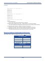
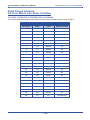
FCC PART 68 INFORMATION
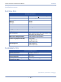
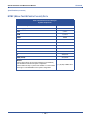
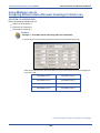
This equipment complies with Part 68 of the FCC Rules. A label, located on the exterior lower left side of the
cabinet, contains the FCC Registration Number(s) and Ringer Equivalence Number (REN).
Notify the local telephone company when you connect the equipment to the network and provide the information
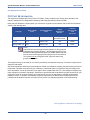
shown in the following table:
Service Order
Code*
Line Type
Facilities Interface
Code
Loop Start
9.0F
02LS2
T1 Line
6.0Y
ISDN (T1/PRI) Line
6.0Y
Ringer
Equivalence
Number*
Universal
Service Order
Code
Connector
See Equipment
Specification Sheet
RJ11
04DU9–1SN
N/A
RJ48C
04DU9–1SN
N/A
RJ48C
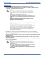
NOTE
State tariffs do not permit ground start operation for KF registered
equipment (key system operation). Ground start operation is only
permitted for MF registered equipment (KTS/PBX hybrids with both
manual and pooled outgoing and incoming access to the network).
The system must be configured for MF operation when using
ground start operation
This equipment may not be used on coin service provided by the telephone company. Connection to party lines is
subject to state tariffs.
Should the equipment cause harm to the telephone network, the telephone company may disconnect your service
temporarily. If possible, they will notify you in advance. If advanced notice is not practical, they will notify you as
soon as possible. You will be informed of your right to file a complaint with the FCC. The telephone company may
make changes in its facilities, equipment, operations or procedures that could affect the proper functioning of your
equipment. If they do so, they will notify you in advance to give you an opportunity to maintain uninterrupted
telephone service. In addition, the telephone company may ask that you disconnect this equipment from the
network until the problem has been corrected or until you are sure that the equipment is not malfunctioning.
FCC Regulations (continued on next page)
- 3-
REGULATIONS
DX-120 Installation Manual - Technical Manual Vol I
FCC Regulations (continued)
TERMS AND DEFINITIONS
Service Order Code (SOC)
Defines type of service and system protection.
EXAMPLES
• 9.0F = analog service, full protection to the network from systems using live
voice. Only registered terminal equipment can be connected to station ports.
• 6.0Y = digital service, provides total protection, including billing protection and
encoded analog content.
Facilities Interface Code (FIC)
A tariff reference used by customers to order correct facilities to be provided by the telco.
EXAMPLES
• 02LS2 = analog service, 2-wire, local switched access, loop-start
• 02RV2-T = analog service, 2-wire, local switched access, reverse-battery
• 04DU9-1SN = digital service, 1.544 Mbps ANSI ESF and B8ZS without line
power
Ringer Equivalence Number (REN)
Useful in determining the quantity of devices that may be connected to the telephone line and still have all of those
devices ring when the telephone number is called. In most, but not all areas, the sum of the REN’s of all devices
connected to one line should not exceed five (5.0). To be certain of the number of devices that you may connect to
your line, you may want to contact your local telephone company to determine the maximum REN for your calling
area.
Universal Service Order Code Connector (USOC Code)
Defines the FCC Part 68 approved telco provided connector, electrically and mechanically, required to interface
with the customer equipment. To avoid legal, warranty, insurance, and casualty problems, do not pass anything
through the network connector other than those permitted in the FCC Part 68 RJ series connectors. Definitions of
connectors are as follows:
EXAMPLES
• RJ21X is a 25 line, 2-wire, T/R, 50 position connector,
• RJ48C is a single line, 4-wire, T/R, T1/R1, 1.544 Mbps, 8-position connector.
Regulations (continued on next page)
- 4-
REGULATIONS
DX-120 Installation Manual - Technical Manual Vol I
Regulations (continued)
INDUSTRY CANADA RF EMISSION INFORMATION
This digital device does not exceed the Class A limits for radio noise emissions from digital apparatus set out in
Radio Interference Regulations of Industry Canada.
Le pre’sent appareil nume’rique n’emet pes de bruits radioe’lectriques de’passant les limits applicables aux
appareils nume’riques de la class A prescrites dans le Re’glement sur le brouillage radioe’lectrique e’dicte’ par le
ministe’re des Industry Canada.
INDUSTRY CANADA TELCO INFORMATION
NOTICE: The Industry Canada label identifies certified equipment. This certification means that the equipment
meets certain telecommunications network protective, operational and safety requirements. Industry Canada does
not guarantee the equipment will operate to the user’s satisfaction.
Before installing this equipment, users should be sure that it is permissible to be connected to the facilities of the
local telecommunications company. The equipment must also be installed using an acceptable method of
connection. In some cases, the company’s inside wiring associated with a single line individual service may be
extended by means of a certified connector assembly (telephone extension cord). The customer should be aware
that compliance with the above condition may not prevent degradation of service in some situations.
Repairs to some certified equipment should be made by an authorized maintenance facility designated by the
supplier. Any repairs or alterations made by the user to this equipment, or equipment malfunctions, may give the
telecommunications company cause to request the user to disconnect the equipment.
Users should be sure for their own protection that the electrical ground connections of the power utility, telephone
lines and internal metallic water pipe system, if present, are connected together. This precaution may be
particularly important in rural areas.
CAUTION
Users should not attempt to make such connections themselves, but should
contact the appropriate electrical inspection authority, or electrician, as
appropriate.
NOTICE
The ringer equivalence number (REN) assigned to each terminal device provides
an indication of the maximum number of terminals allowed to be connected to the
telephone interface. The termination on an interface may consist of any
combination of devices subject only to the requirement that the sum of the ringer
equivalence numbers of all the devices does not exceed 5.
Industry Canada TELCO Information (continued on next page)
- 5-
REGULATIONS
DX-120 Installation Manual - Technical Manual Vol I
Industry Canada TELCO Information (continued)
AVIS
L’etiquette de Industrie Canada identifie le materiel homologue. Cette etiquette
certifie que le materiel est conforme a certaines normes de protection,
d’exploitation et de securite des reseaux de telecommunications. Le Ministere
n’assure toutefois pas que le materiel functionnera a la satisfaction de l’utilisateur.
Avant d’installer ce materiel, l’utilisateur doit s’assurer quil est permis de le
raccorder aux installations de l’entreprise locale de telecommunication.
Le materiel doit eqalement etre installe en suivant une methode acceptee de
raccordement. L’abonne ne doit pas oublier qu’il est possible que la conformite
aux conditions enoncees ci-dessus n’empeche pas le degradation du service
dans certaines situations. Les reparations de materiel homologue doivent etre
effectuees par un centre d’entretien canadien autorise designe par le fournissuer.
La compagnie de telecommunications peut demander a l’utilisateur de
debrancher un appareil a la suite de reparations ou de modifications effectuees
par l’utilisateur ou a cause de mauvais fonctionnement. Pour sa propre
protection, l’utilisateur doit s’assurer que tous les fils de mise a la terre de la
source d’energie electrique, des lignes telephoniques et des canalisations d’eau
metalliques, s’il y en a, sont raccorde ensemble. Cette precaution est
particulierement importante dans les regions ruales.
AVERTISSEMENT
L’utilisateur ne doit pas tenter de faire ces raccordements luimeme; il doit avoir
recours a un service d’inspection des installations d’inspection des installations
electriques, ou a un electricien, selon le cas.
AVIS
L’indice d’equivalence de la sonnerie (IES) asssigne a chaque dispositif terminal
indique le norbre maximal de terminaux qui peuvent etre raccordes a une
interface. La terminaison d’une interface telephonique peut consister en une
combinaison de quelques dispositifs, a la seule condition que la somme d’indices
d’equivalence de la sonnerie de tous les dispositifs n’excede pas 5.
- 6-
DX-120 Installation and Maintenance Manual
SECTION 1 - INTRODUCTION
USING THIS MANUAL
This publication contains a technical discussion of the digital telephone system. It provides step-by-step
instructions for installation. You should become familiar with this manual before you attempt to install the system.
This manual provides the following information:
• Regulatory and Safety Considerations
• Description of the hardware
• An understanding of the operational characteristics of the system hardware components
• Instructions for installing the cabinet, printed circuit boards, and ancillary equipment
HINT
It is also a good idea to review the companion document for this Installation Manual:
DX-120 Programming and Maintenance Manual - Technical Manual Vol II.
All of the Vertical publications are available for download from Vertical’s Customer Care Center, located at http://
www.vertical.com/ccc. Should you need hard copies of these publications, contact your Vertical inside sales
representative.
Vertical Communications, Inc.
Inside Sales Department
106 Cattlemen Road
Sarasota, Florida 34232
1-800-Comdial
- 7-
USING THIS MANUAL
DX-120 Installation and Maintenance Manual
Locating Documentation
Vertical technical publications are numbered according to their intended function. Various publications pertaining
to the products offered by Vertical can be found at http://vertical.com/ccc. If you are unfamiliar with the CCC,
please contact Technical Support for details about logging in.
Document Prefix
Document Type
Purpose
AG
Attendant Guide
Contains information required for programming and using a system attendant.
FLDII
Field Installation Instructions
Contains basic information as a quick reference for programming in the field (vs.
remote programming)
GCA
General and Descriptive Information
Provides general information for the operation of features or hardware. This may
include programming manuals as well as
user guides.
(generally refers to Vertical documents
created or edited prior to 11/06)
Installation and Maintenance
Instructions
Provides instructions for Installing and
Maintaining various Vertical (Comdial)
products.
Programming Instructions
Provides programming information
required for a particular product.
PRN
Product Release Notice
Contains information about any new product that may have recently been released
QR
Quick Reference
Provides concise, abbreviated installation, programming, or operating information in a one or two page document.
SAB
Service Advisory Bulletin
Provides information to alert the field
about specific service related issues.
SRN
Software Release Notice
Provide information about a new software
release. These notices may be for new
feature releases or maintenance.
SUPG
Supervisor’s Guide
Provides information specific to supervisor’s on particular systems that allow a
supervisor to use and program a variety of
additional features.
TAB
Technical Advisory Bulletin
Publications that are intended to offer specific technical information related to a particular product.
UG
User Guide
Provides information specific to end-users
(e.g., those who use a phone at their desk
vs. someone who installs and/or programs
the system).
IMI
or
IM
PRG
or
PRGM
- 8-
OVERVIEW
DX-120 Installation and Maintenance Manual
OVERVIEW
The Vertical DX-120 is a fully digital hybrid key telephone system. The DX-120 uses a mix of “loop start” central
office (telephone company) line interfaces and digital lines such as T1 or ISDN (T1-PRI), along with a mix of analog
and digital extension ports to provide office communications and connectivity to the Public Switched Telephone
Network (PSTN).
The DX-120 delivers a vast array of office productivity features and telephone use enhancing features, including
Caller Identification (requires telephone company subscription), in the standard package. Unlike most systems that
support Caller ID, the DX-120 supports Caller ID to DX-120 proprietary digital extensions and to third-party, Caller
ID capable analog devices (cordless telephones, etc.)
Although most features are standard, the DX-120 provides for several optional features to further enhance office
communications. Built-in voice processing integration packages include:
• Automated Attendant
• Four port, Flash-based Voice Mail/Auto Attendant (expandable to 8 ports)
• Four port, Hard drive-based Voice Mail/Auto Attendant (expandable to 8 ports)
The DX-120 platform allows you to use these voice processing platforms without losing valuable system port
resources.
The DX-120 is comprised of an application configured, expandable Key Service Unit (KSU) platform. There is one
fully-featured Digital Executive Telephone (DET) that delivers access to all system functions. The system
architecture provides an expandable interface for digital port growth and analog port growth. The basic
configuration supports both device types. Analog ports might be used for plain old telephones, fax machines,
modems, etc. The DX-120 is designed to meet the telecommunications needs of small-to-medium business
offices.
System Technology
• The DX-120 incorporates state-of-the-art digital technology for voice switching and call processing, using
Pulse Code Modulation and Time Division Multiplexing (PCM/TDM).
• The DX-120 is a non-blocking switch, with no loss or degradation of voice signals.
• The system is stored-program control and uses a ARM7 main microprocessor and peripheral devices
(extensions and CO lines) in a distributed processing configuration.
• Memory consists of 640K bytes of ROM (Read Only Memory) and 384K bytes of RAM (Random Access
Memory). The RAM is lithium battery protected.
• The maximum system configuration is 16 loop start, 24 digital lines, 88 extensions (80 digital and 8 analog)
and 8 voice processing channels.
System Technology (continued on next page)
- 9-
OVERVIEW
DX-120 Installation and Maintenance Manual
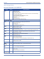
System Technology (continued)
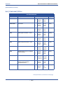
AVAILABLE EQUIPMENT FOR THE DX-120
DEVICE
KSU1
PART #
7201
CHARACTERISTICS
8 digital extension ports
4 analog device ports
4 CID-ready CO line ports.
2 music source inputs, can be assigned as desired to CO lines for hold music/messages
1 power failure port (CO line 1).
1 control contact (LBC, Gate, External Page Control)
1 external paging equipment interface
2 serial ports
PC-DBA programming
SMDR (Station Message Detailed Recording)
OPTIONAL EQUIPMENT
KSU2
7202
• Used to expand the system capacity beyond KSU1 limits.
• 8 digital extension ports
• 4 CO line ports
• 1 power failure port (CO line circuit 1).
DPM8
7220
• Digital Port Module - 8 circuit
• Installs into KSU1 or KSU2
APM4
7230
• Analog Port Module - 4 circuit
• Always factory-installed into KSU1; can also be connected to KSU2 via dedicated cable
COM4
7210
• CO line Module - 4 circuit with one power failure port on first CO line circuit
• Installs into KSU1 or KSU2
MDM
7249
• Modem Module, for use with off-site programming.
• Installs into KSU1 only.
AAM
7240
• Automated Attendant Module
• 4 port, one menu for routing
• 10 announcements for various caller greetings. Installs into KSU1 only
DPM16
7221
• Digital Port Module - 16 circuit
• Installs into KSU1 or KSU2
T1
7290
• T1 Digital Trunking - 24 channels
ISDN
(T1/PRI)
7285
• ISDN (T1/PRI) Digital Trunking - 23 channels plus D-channel
CO DX FLASH
VM
7271C
CO DX HD VM
7270C
• Flash-based, 4-port Voice Mail (Corporate Office DX) with Auto Attendant.
• 1.5 hours storage and 100 mailboxes.
• Hard Drive-based, 4-port Voice Mail (Corporate Office DX) with Auto Attendant and onboard modem.
• 100 hours storage and 100 mailboxes.
CO DX 4-port
Expansion VM
7273
• 4 port expansion to 7271C or 7270C.
- 10 -
OVERVIEW
DX-120 Installation and Maintenance Manual
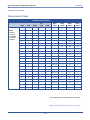
Configuration
The Vertical DX-120 platform is comprised of one full-featured key telephone model and two modular KSUs (Key
Service Units). Several modules are available for enhanced system applications and configuration expandability.
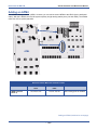
KSU1 COMPONENTS
The CPM (Central Processor Module) is installed inside of KSU1 and connected to the 408M ribbon cable J4 (also
labeled “To CPM”).
• The CPM contains:
-
Two serial ports
-
Two music ports
-
One control contact (external paging/LBC/gate control)
-
One external page equipment interface connection
-
Socket connectors for the KSU2 (labeled “2nd Cabinet”), MDM, and VP modules (AAM, 7271C, and
7270C)
• The standard 408M (part of 7201) contains:
-
4 CO line ports
-
1 power failure transfer port for the first CO line circuit
-
8 digital ports
-
a ribbon cable (J1, also labeled “COM4”) for connection to the COM4 module (PN 7210) in KSU1
-
ribbon cable sockets (J2 and J3, also labeled “To DPM8”) for connection of DPM8 (PN 7220) or
DPM16 (PN 7221) module
• The standard APM4 (part of 7201) contains four analog device ports (installed on ribbon cable J5, also
labeled “APM4”)
KSU2 COMPONENTS
The standard 408E contains:
• 4 CO line ports
• 1 power failure transfer port for the first CO line circuit
• 8 digital ports
• a ribbon cable J1, also labeled “COM4”) for connection to the COM4 module (PN 7210)
• ribbon cable sockets J2 and J3, also labeled “To DPM8”) for connection of DPM8 (PN 7220) or
DPM16 (PN 7221) module
• a shielded cable (J4) for connection to CPM socket JP2 (also labeled “2nd Cabinet”) in KSU1
Configuration (continued on next page)
- 11 -
OVERVIEW
DX-120 Installation and Maintenance Manual
Configuration (continued)
VOICE PROCESSING MODULES
The DX-120 provides several voice processing (or voice mail) options. The optional voice processors that you can
add to the DX-120 are fixed system resources that do not require peripheral device ports (analog or digital). This
significant advantage means that the DX-120 VP options can be added to any DX-120 configuration without “port
loss” thus eliminating the ill effects of reducing the overall capacity of the system when the voice processor is
connected. Because the DX-120 doesn’t use conventional peripheral ports to interface the VPs, we refer to the VP
connectivity in terms of “channels.”
• AAM (Automated Attendant Module): The AAM provides four channels for automated attendant operation
only. The AAM is then capable of handling four calls simultaneously. Callers answered by the AAM are
greeted by one of four greetings associated with the DX-120 mode of operation (Day / Evening / Alternate /
Temporary). Various other announcements are also included for caller processing, refer to the DX-120
Technical Manual, Volume II, Programming for further details.
• 7271C (Flash-based, four port VM with Automated Attendant): The 7271 provides four channels for
automated attendant and voice mail operation. The 7271 is equipped to support up to 100 voice mailboxes
and 3.2 hours of message storage (including the various greeting announcements).
• 7270C (Hard Drive-based, four port VM with Automated Attendant): The 7270C provides four channels
for automated attendant and voice mail operation. The 7270C is equipped to support up to 2000 voice
mailboxes and 150 hours of message storage (including the various greeting announcements).
• 7273 (Four port expansion card): The 7273 is added to the 7271C or 7270C to increase the total number of
voicemail ports from four (4) to eight (8).
NOTE
• For details on installing the 7271C and 7270C refer to the Corporate Office DX
Installation Instructions.
• All of the these voice processors are connected to the DX-120 CPM via
specific interface sockets.
Configuration (continued on next page)
- 12 -
OVERVIEW
DX-120 Installation and Maintenance Manual
Configuration (continued)
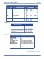
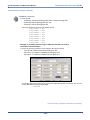
CONFIGURATION TABLE
SYSTEM CONFIGURATION
Equipment
T1 or
COM4
KSU1*
7201P-00
71201P-04
standard)
Analog
Digital
Analog
Trunks
Trunks
Stations
Stations
4
8
4
1
4
16
4
2
4
24
4
4
32
4
8
8
4
DPM8
1
(one APM4
included as
Digital
DPM16
ISDN
APM4
1
1
1
1
8
16
4
1
2
8
24
4
1
1
1
8
32
4
1
4
24
4
2
4
40
4
1
1
8
24
4
1
2
8
40
4
1
24 \ 23
4
8
4
1
1
24 \ 23
4
16
4
2
1
24 \ 23
4
24
4
1
24 \ 23
4
32
4
1
24 \ 23
8
8
4
1
1
1
1
1
1
24 \ 23
8
16
4
1
2
1
24 \ 23
8
24
4
1
1
1
1
24 \ 23
8
32
4
1
1
24 \ 23
4
24
4
2
1
24 \ 23
4
40
4
1
1
1
24 \ 23
8
24
4
1
2
1
24 \ 23
8
40
4
*This configuration does not allow space for voicemail.
System Configuration (continued on next page)
- 13 -
OVERVIEW
DX-120 Installation and Maintenance Manual
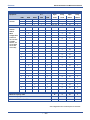
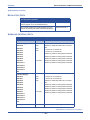
SYSTEM CONFIGURATION (continued)
Equipment
T1 or
COM4
DPM8
DPM16
KSU1*
7201P-08
1
1
ISDN
APM4
Digital
Analog
Digital
Analog
Trunks
Trunks
Stations
Stations
1
24 \ 23
4
8
4
1
24 \ 23
4
16
4
1
24 \ 23
4
24
4
4
8
KSU2
7202P-00
1
4
16
adds to
KSU1
2
4
24
configuration
1
4
32
8
8
(KSU2 does
1
1
not come with
an APM4.
However, one
can be added
via the dedicated cable)
1
1
8
16
1
2
8
24
1
1
1
8
32
1
4
24
2
4
40
1
1
8
24
1
2
8
40
1
4
8
4
1
1
4
16
4
2
1
4
24
4
1
4
32
4
1
8
8
4
1
1
1
1
1
1
8
16
4
1
2
1
8
24
4
1
1
1
1
8
32
4
1
1
4
24
4
2
1
4
40
4
1
1
1
8
24
4
1
2
1
8
40
4
8
40
4
8
40
4
16
80
8
Maximum Capacity KSU1
24
Maximum Capacity KSU2
TOTAL SYSTEM CAPACITY
24
*This configuration does not allow space for voicemail.
- 14 -
OVERVIEW
DX-120 Installation and Maintenance Manual
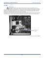
Key Service Unit
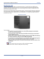
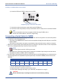
The DX-120 Key Service Unit (KSU) is a modular flat-pack design. Two KSU’s (KSU1 and KSU2) may be
equipped to achieve the total system capacity of 16 loop start, 24 digital lines, 88 extensions (80 digital and 8
analog) and 8 voice processing channels. KSU1 is factory equipped with one 408M, one APM4 and the CPM.
KSU2 is factory equipped with one 408E.
Each KSU is a self-contained cabinet with internal power supply. The power supply AC transformer voltage switch
can be set for either 117vac or 230vac operation. (It is factory set for 117vac operation.) The KSU is designed to
be mounted on the wall and is shipped with a wall mounting template. The compact KSU weighs less than 20
pounds and is UL Listed.
DX-120 Key Service Unit (KSU)
You can remove:
• Or reposition four panels installed over various KSU openings to accommodate
exterior connection requirements.
• One panel to route a serial cable through the KSU outer housing for connection of
ancillary SMDR equipment.
• Another panel to route a serial (NULL Modem) cable through the KSU outer housing
for direct connection of a PC for on-site PC-DBA programming.
• Or reposition the remaining KSU panel to accommodate cables entering through the
outer housing for connecting station/extension cables or to the MDF.
• The panel covering the jacks on the phone boards (located under the left side of the
main board).
NOTE
From the exterior, with covers in place, the KSU1 and KSU2 look identical.
However, KSU1 contains the CPM (system call processing).
- 15 -
OVERVIEW
DX-120 Installation and Maintenance Manual
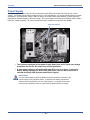
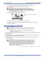
Power Supply
The power supply circuitry of the DX-120 incorporates a linear design AC transformer with a choice of input
voltage. The voltage selector switch is shipped set for 117vac applications; you can also set this switch for 230vac
applications. Since the power supply is linear in design, the output voltage varies between 21.6vdc and 32vdc
depending on load and stability of the input voltage. The output voltage is delivered to the 408M (in KSU1, 408E in
KSU2) for voltage regulation. All system operation and logic voltages are produced at the 408M/E.
Voltage Selector Switch
• Two fuses are equipped on the power supply board, one for AC input over-voltage
protection and one for DC output over-current protection.
• A main power switch is accessible when the KSU cover is in place. In the event
battery backup operation is desired the KSU power cord can be connected to a
external (ancillary) UPS (Uninterrupted Power Supply).
IMPORTANT!
It is your responsibility to match the battery requirements/UPS requirement to the
specific needs of the equipment owner. To determine the battery requirement
needs and UPS requirement, see see “Specifications” to find the current draw
and necessary Amp/Hour back up support that the battery/UPS must supply.
- 16 -
OVERVIEW
DX-120 Installation and Maintenance Manual
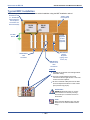
CPM (Central Processor Module)
The CPM module is equipped standard in KSU1. This board contains all circuitry required to control the fully
equipped DX-120. The system uses the CPM to perform all digital voice switching and call processing data
switching.
The CPM has one ribbon cable connector for connection to the KSU1 408M and six (6) connector sockets for
connection of the system built-in modem, voice processor, and second cabinet (KSU2). Since the CPM comes
installed inside of KSU1 the CPM ribbon cable is already in place and connected to the KSU1-408M J5 socket.
Assuming the orientation of the KSU1 cabinet is installed on the wall; the two horizontal connector sockets in the
upper right corner of the CPM are for the MDM (Modem Module). The connector socket labeled “2nd Cabinet” is
for connection to theKSU2/408E if that expansion is required. The remaining two connector sockets on the CPM,
one at the left side, the other at the right side are for the voice processor solution.
NOTE
The voice processor solution can be any of three possible choices: AAM, 7271C,
or 7270C.
• The CPM also provides the following standard connectors:
-
Music Channel 1 - On Hold/Background Music Interface
-
Music Channel 2 - On Hold/Background Music Interface
-
Control Contact (Loud Bell / Door / External Page Control)
-
External Paging Equipment Interface
-
RMP Serial Port - for onsite PC-DBA system database programming
-
SMDR Serial Port - for connection to ancillary SMDR/Call Accounting equipment
-
T1 or ISDN (T1/PRI)
• The CPM has two option strap jumpers one for database start-up (JE1) and one for music channel one source
(internal/external) selection (JPC1).
-
JE1 Cold Start/Normal is used to force load database default factory settings. This jumper will normally
never require operation after the initial power up sequence is completed. However should the need arise
to return the site database to the factory settings this jumper is used to perform a cold start.
-
JPC1 Internal/External is used to select the Music Channel 1 source. The DX-120 provides a
synthesized music source for music on hold, in applications where no music source is available. The
synthesized tune is repeated. JPC1 is in the “EXT” (i.e, external) position when it ships from the factory.
- 17 -
OVERVIEW
DX-120 Installation and Maintenance Manual
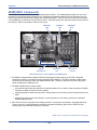
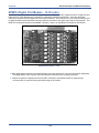
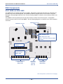
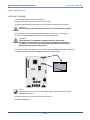
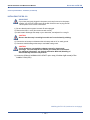
408M (KSU1 Component)
The 408M is the large circuit board that is packaged inside of KSU1. The 408M provides interface for up to four
loop-start CO lines and 8 digital extension ports. Additionally the 408M regulates the 24 volt DC power from the
source to produce all required logic voltages and operations voltages. There is also a Power Failure Port located
on the 408M that is connected to the first CO line circuit. Whenever power fails, this port becomes active with dial
tone from the CO line connected to the first CO line port.
APM4 Ribbon
Cable
8 Digital
Extension Ports
CPM Ribbon
Cable
Power Failure
Port
COM4 Ribbon
Cable
4 Loop Start Co
Line Ports
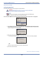
KSU1 shown with cover – CPM and APM4 removed (408M exposed)
• The 408M is equipped with a heartbeat LED that indicates processing activity on the PCB. The 408M
peripheral processor is operating when the heartbeat LED is flashing. The KSU1 operation LED (located
next to the power switch) is tied to the 408M heartbeat LED. Therefore, when the LED next to the power
switch is flashing, the 408M is active.
• The KSU1-408M has three ribbon cables:
-
located at the upper right and oriented in a horizontal position, the J1 cable is used to interface a COM4 if
required to expand the system CO line capacity.
-
located at the upper center and oriented in a vertical position, the J4 cable is used to interface the DX-120
CPM.
-
located at the upper center and oriented in a vertical position, the J5 cable connects to the standard
APM4 installed in KSU1.
• Each CO line circuit incorporates over-voltage protection, ring detector, loop detector, loop/pulse-dial relay,
current sink circuit, coupling/isolation transformer (impedance 600:600), hybrid circuit, CODEC & filter,
polarity guard circuit and radio frequency noise filter.
408M - KSU1 Component (continued on next page)
- 18 -
OVERVIEW
DX-120 Installation and Maintenance Manual
408M - KSU1 Component (continued)
• The fourth CO line port is equipped with CNG fax tone detection circuitry. When programmed as a “FAX” line,
this circuit will automatically engage the FAX Tone detector. If FAX tone is detected, the system routes the
call to the analog port designated as the destination for fax calls.
• Each digital port (connects to Digital Executive Telephones and DSS Consoles) is comprised of a proprietary
octal ASIC (Application Specific Integrated Circuit) transceiver. There are three data channels in operation at
each digital port via the octal transceiver. One channel is used for call processing control of digital terminal
functions/operations and two channels are used for the digital voice channel requirements.
• Each digital station interface is protected against circuit wiring shorts by an over-current protection polyswitch.
The digital station circuit requires only one cable pair to operate and is not polarity sensitive.
• Physical connection of digital extensions, power failure telephones, and CO lines to the 408M module is made
through convenient RJ-11 connectors along the bottom edge of the module.
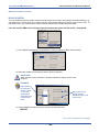
408E (KSU II Component)
The 408E is very similar to the 408M; however, it is unique to KSU2. The 408E provides interface for up to 4
loop-start CO lines and 8 digital extension ports. In addition, the 408E regulates the 24-volt DC power from the
source to produce all required logic voltages and operations voltages. There is also a power failure port located on
the 408E that is associated to the first CO line circuit. Whenever power fails this port becomes active with dial tone
from the CO line connected to the first CO line port.
KSU2
• The 408E is equipped with a heartbeat LED that indicates processing activity on the PCB; the 408E peripheral
processor is operating when the heartbeat LED is flashing. The KSU2 operation LED (located next to the
power switch) is tied to the 408E heartbeat LED, therefore, when the LED next to the power switch is
flashing, the 408E is active.
• The KSU2-408E connections are almost identical to those on the 408M (KSU1); the exception is the long
shielded cable used to connect KSU2 to the CPM inside of KSU1.
NOTE
There is no standard APM4 installed inside of KSU2. However, one can be
connected using the dedicated cable.
408E - KSU2 Component (continued on next page)
- 19 -
OVERVIEW
DX-120 Installation and Maintenance Manual
408E - KSU2 Component (continued)
• Each CO line circuit incorporates over-voltage protection, ring detector, loop detector, loop/pulse-dial relay,
current sink circuit, coupling/isolation transformer (impedance 600:600), hybrid circuit, CODEC & filter,
polarity guard circuit and Radio Frequency noise filter.
• The fourth CO line port is equipped with CNG Fax Tone Detection circuitry. When programmed as a “FAX”
line, this circuit automatically engages the FAX tone detector. If FAX tone is detected, the system routes the
call to the analog port designated as the destination for fax calls.
• Each digital port (connects to Digital Executive Telephones and DSS Consoles) is comprised of a proprietary
octal ASIC (Application Specific Integrated Circuit) transceiver. There are three data channels in operation at
each extension port via the octal transceiver: one channel is used for call processing control of digital
terminal functions/operations and two channels are used for the digital voice channel requirements.
• Each digital station interface is protected against circuit wiring shorts by an over-current protection Polyswitch.
The digital station circuit requires only one cable pair to operate and is not polarity sensitive.
• Physical connection of digital extension terminals, power failure telephones, and CO lines to the 408M
module is made through convenient RJ-11 connectors along the bottom edge of the module.
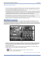
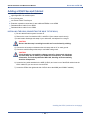
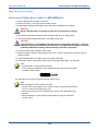
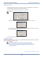
APM4 (Analog Port Module - 4 Circuits)
The APM4 provides four separate analog device ports. This allows the DX-120 to support auxiliary office
equipment such as fax machines, PC/FAX modems, and analog telephones (single line telephones). The APM4
generates -30VDC and 20-25Hz, 50V square wave ringing for operation.
APM4 (Analog Port Module - 4 Circuits)
• The APM4 is equipped with a heartbeat LED that indicates processing activity on the PCB; the APM4
peripheral processor is operating when the heartbeat LED is flashing.
• The APM4 provides DTMF receivers for each analog port. Ancillary analog devices connected to APM4
analog ports must generate DTMF signaling.
IMPORTANT
Pulse (rotary-dial) telephones/equipment are not supported.
APM4 - Analog Port Module (continued on next page)
- 20 -
OVERVIEW
DX-120 Installation and Maintenance Manual
APM4 - Analog Port Module (continued)
• All connections are via RJ-11 connectors along the bottom edge of the module. KSU1 is delivered with one
APM4 installed on ribbon connector J5 as standard equipment.
• APM4’s may be installed on 408M/E-J5 (standard in KSU1:408M-J5 or KSU2 via dedicated cable).
IMPORTANT
DO NOT ATTEMPT to install an APM4 on J2 or J3.
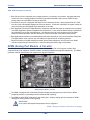
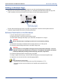
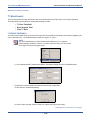
DPM8 (Digital Port Module - 8 Circuits)
The DPM8 module expands the DX-120 system capacity of digital ports DET (Digital Executive Telephones) and
DSS consoles. Each digital port is comprised of a proprietary octal ASIC transceiver. There are three data
channels in operation at each digital port via the octal transceiver. One channel is used for call processing control
of digital terminal functions/operations and two channels are used for the digital voice channel requirements. The
DPM8 is controlled directly from the 408M/E; therefore, there is no heartbeat LED located on the DPM8.
DPM8 (Digital Port Module - 8 Port)
• Each digital station interface is protected against circuit wiring shorts by an over-current protection Polyswitch.
The digital station circuit requires only one cable pair to operate and is not polarity sensitive.
• Physical connection of digital port terminals (DET and DSS) to the DPM8 module is made through convenient
RJ-11 connectors along the bottom edge of the module.
- 21 -
OVERVIEW
DX-120 Installation and Maintenance Manual
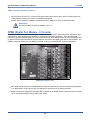
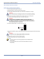
DPM16 (Digital Port Module - 16 Circuits)
The DPM16 module expands the DX-120 system capacity of digital ports DET (Digital Executive Telephones) and
DSS consoles. Each digital port is comprised of a proprietary octal ASIC transceiver. There are three data
channels in operation at each digital port via the octal transceiver. One channel is used for call processing control
of digital terminal functions/operations and two channels are used for the digital voice channel requirements. The
DPM16 is controlled directly from the 408M/E. Therefore, there is no heartbeat LED located on the DPM16.
DPM16 (Digital Port Module - 16 Port)
• Each digital station interface is protected against circuit wiring shorts by an over-current protection Polyswitch.
The digital station circuit requires only one cable pair to operate and is not polarity sensitive.
• Physical connection of digital port terminals (DET and DSS) to the DPM16 module is made through
convenient RJ-12 connectors along the bottom edge of the module.
- 22 -
OVERVIEW
DX-120 Installation and Maintenance Manual
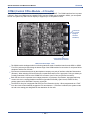
COM4 (Central Office Module - 4 Circuits)
The COM4 module is installed in the dedicated position via J1 of the 408M/E. The COM4 interfaces four loop-start
CO lines. Since one COM4 may be installed in KSU1 and one COM4 may be installed in KSU2, you can expand
the DX-120 system loop start CO line capacity to support up to 16 loop start CO lines.
CO line Ports
1-4 (Circuit 4
Equipped
with CNG
FAX Detect)
Power Failure Transfer Port—
associated to CO Line Port 1
COM4 (Central Office Module - 4 Port)
• The COM4 module is shipped with four mounting stand-offs used to install the board into the KSU1 or KSU2.
Five RJ11 jacks are provided along the bottom edge of the COM4 module for connection of one power failure
telephone and the four CO lines.
• CO lines are terminated at the site by the telephone company at a point of interface called the Demarcation
(Demarc). When ordering CO lines for the site, request termination on RJ11 type jacks. Doing so allows you
to easily extend the CO lines to the COM4 RJ11 connector (one CO line per jack and connector).
• Each CO line circuit incorporates over-voltage protection, ring detector, loop detector, loop/pulse-dial relay,
current sink circuit, coupling/isolation transformer (impedance 600:600), hybrid circuit, CODEC & filter,
polarity guard circuit, and Radio Frequency noise filter.
• The fourth CO line port is equipped with CNG Fax Tone Detection circuitry. When programmed as a “FAX”
line, this circuit will automatically engage the FAX tone detector. If FAX tone is detected, the system routes
the call to the analog port designated as the destination for fax calls.
- 23 -
OVERVIEW
DX-120 Installation and Maintenance Manual
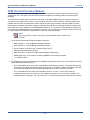
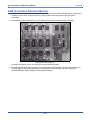
MDM (Modem Module)
The 7249 Modem Module is a self-contained integrated modem unit that is installed at J5 and J6 in the upper right
corner of the CPM. The integrated MDM allows you to access the system programming and remote maintenance
utilities from an off-site location (password verification is required).
MDM (Modem Module)
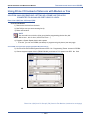
• When the MDM is installed, you can program the system remotely using PC-DBA.
NOTE
PC-DBA is included in the utilities CD shipped with every new system. Or, you
can obtain PC-DBA at the Vertical web site, www.vertical.com.
• You can service the system, using PC-DBA and a modem in your PC, to place a call to the site where the DX120 is installed.
NOTE
If one of the voice processing systems are installed, routing to the modem
extension is automated. Otherwise, the person who answers this data call must
transfer the call to extension 100. Once the modems have established the data
connection, you can begin servicing the switch.
IMPORTANT
The MDM default extension number is 100. This number can be changed and
therefore may be different for some DX-120 systems.
- 24 -
OVERVIEW
DX-120 Installation and Maintenance Manual
AAM (Automated Attendant Module)
• The Automated Attendant Module is a self contained integrated module that enables automatic answering of
selected CO lines and a single-level menu for greeting callers and routing them to DX-120 system
destinations.
• The AAM can handle all call traffic or act as a backup to the primary answering system attendant.
AAM (Automated Attendant Module)
• The AAM is installed at J3 and J4 of the CPM (centered above the board).
• The AAM provides 10 announcements for the various modes of system/action operation: Day Greeting, Alt
Greeting, Night Greeting, Waiting Message, Invalid Message, Busy Message, No Answer Message,
Goodbye Message, Inquiry Message, and Temporary Message.
- 25 -
OVERVIEW
DX-120 Installation and Maintenance Manual
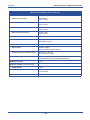
T1 Card (T1 Module) Details
The T1 Card (T1 Module) allows for expansion of the DX-120 system CO line interface to a capacity maximum of
24 digital CO line ports.
T1 Module
T1 Card (T1 Module) Details
Capacity:
• One (1) T1(1.544Mbps, 24channels) interface
Network interface mode
• T1-Interface
Network connector
• RJ-45
LED indicator
• T1 Card has 9 LEDs on the PCB which indicate alarms of T1 trunk,
in-use status, and synchronous clock enable status.
LED # Function
• D2 Yellow Alarm Indicator
• Normal=Dark
• Alarm = Red lit
• D3 AIS Alarm Indicator
• Normal =Dark
• Alarm = Red lit
• D4 Loss of Frame Alarm Indicator
• Normal = Dark
• Alarm = Red lit
• D5 No Signal Alarm Indicator
• Normal = Dark
• Alarm = Red lit
• D6 PRI Link Channel Sync.
• For T1 card = Always Dark
• D7 Clock Mode Indicator,
• Master Mode = Dark
• Slave Mode = Green lit
• D8 T1/E1 Indicator
• T1 = Green lit
• E1= Dark
• D9 Heart Beat
• Normal = Flashing
• Abnormal = Dark or Steady Green lit
T1 Card (T1 Module) Details (continued on next page)
- 26 -
OVERVIEW
DX-120 Installation and Maintenance Manual
T1 Card (T1 Module) Details (continued)
• D10 Signaling Synchronization indicator
• Synchronous = Green lit
• Non-Synchronous = Dark
Clock source
• On-board crystal and can be set as master or slave to synchronize
with PSTN, depending upon the networking requirement.
Backplane connector
• 15-pin
Backplane interface covers the following:
• Power feeding
• 5 VDC
• PCM highway
• System will provide an 8KHz frame signal for T1 card’s
synchronization.
• Control data interface
• Compatible with SPI (Serial Peripheral Interface) bus timing.
ISDN Card (T1/PRI Module) Details
The ISDN Card (T1/PRI Module) allows for expansion of the DX-120 system CO line interface to a capacity
maximum of 23 Digital CO line ports.
ISDN Card (T1/PRI Module)
ISDN Card (T1/PRI Module) Details
Capacity:
One (1) T1(1.544Mbps, 24channels) interface
Network interface mode
ISDN (T1/PRI) Interface
Network connector
RJ-45
LED indicator
ISDN (T1/PRI) Card has 9 LEDs on the PCB which indicate alarms of
T1 trunk,
in-use status, and synchronous clock enable status.
ISDN Card (T1/PRI Module) Details (continued on next page)
- 27 -
OVERVIEW
DX-120 Installation and Maintenance Manual
ISDN Card (T1/PRI Module) Details (continued)
LED # Function
• D2 Yellow Alarm Indicator
Normal=Dark
Alarm = Red lit
• D3 AIS Alarm Indicator
Normal =Dark
Alarm = Red lit
• D4 Loss of Frame Alarm Indicator
Normal = Dark
Alarm = Red lit
• D5 No Signal Alarm Indicator
Normal = Dark
Alarm = Red lit
• D6 PRI Link Channel Sync.
ISDN (T1/PRI) Working = Steady Green
• D7 Clock Mode Indicator,
Master Mode = Dark
Slave Mode = Green lit
• D8 ISDN (T1/PRI) Indicator
ISDN (T1/PRI) = Green lit
• D9 Heart Beat
Normal = Flashing
Abnormal = Dark or Steady Green lit
• D10 Signaling Synchronization indicator
Synchronous = Green lit
Non-Synchronous = Dark
Clock source
On-board crystal and can be set as master or slave to synchronize with
PSTN, depending upon the networking requirement.
Backplane connector
15-pin
Backplane interface covers the following:
• Power feeding
5 VDC
• PCM highway
System will provide an 8KHz frame signal for ISDN (T1/PRI) card’s
synchronization.
• Control data interface
Compatible with SPI (Serial Peripheral Interface) bus timing.
- 28 -
OVERVIEW
DX-120 Installation and Maintenance Manual
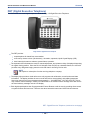
DET (Digital Executive Telephone)
The DX-120 has one model digital telephone called the Edge 120 Digital Executive Telephone.
Edge 120 DET - Digital Extension Telephone
• The DET provides:
-
a speakerphone for hands-free conversations
-
a two-row by sixteen column (32-character), dot-matrix, supertwist, Liquid Crystal Display (LCD)
-
three interactive buttons to enhance system feature operation.
• The supertwist LCD eliminates the need for contrast adjustment, and enhances clarity of displayed data using
an angled viewing position. Since the DX-120 includes Caller ID (CID) as a standard feature, the LCD also
provides every designated ringing extension with CID data for incoming CO line calls.
NOTE
CID requires a subscription from the servicing telephone company.
• The display also provides a visual reference to call progress and call duration, as well as time and date
information. The display enables the user to send and receive visual advisory and callback messages.
Users may select from six pre-programmed messages (i.e., “IN A MEETING,” “OUT OF OFFICE”), or they
may create a custom message. Callers from other DETs to an extension with a message active will receive
the visual advisory message on their LCD display.
• Each digital speakerphone has 30 programmable Feature Buttons to aid the user by providing direct access
to system features and resources. There are also three interactive buttons and 9 fixed function buttons.
DET - Digital Extension Telephone (continued on next page)
- 29 -
OVERVIEW
DX-120 Installation and Maintenance Manual
DET - Digital Extension Telephone (continued)
• Each DET is equipped standard with a 2.5 millimeter headset jack. Users can toggle their speakerphone
operation in and out of a special “headset mode”. This mode allows the user to easily activate the headset
jack via the ON/OFF button as an alternative to using the speakerphone. Thus, headset mode is easily
enabled or disabled so that users can quickly select between use of the headset or speakerphone
operations.
NOTE
The DET must be idle to change this setting.
• You can mount the telephone in one of three positions: low and low profile desk positions and the wall
mounted position.
• Each speakerphone is also equipped with a status lamp to aid in user operations. The lamp is dual color (red
/ green) and indicates various modes of operation, such as messages/voice messages waiting, incoming
calls - distinctive for CO and intercom, in-use indication for speakerphone mode, headset mode, etc.
• The Multiple Call Handling utility known as Call Key (Feature Code 66) provides a method for tracking the
status for a “pool” of CO lines. More specifically, the Call Key reflects the status of any active Trunk calls for a
specific extension (assuming there is not a Line Key programmed for that individual CO line that the Trunk
call is associated with). Furthermore, users can program multiple Call Keys on their phone to allow for
tracking the status and management of additional, simultaneous Trunk calls.
• There are two types of lamp indicators on the phone: General and Hold. General lamp indicators appear next
buttons to provide general call status. The Hold lamp indicators provide status with regard to any calls on
hold (either trunk or intercom). Refer to the Edge 120 DET User Guide for more information.
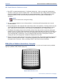
DSS (Direct Station Selection) Console
The DSS console is a digitally interfaced component of the DX-120. It connects to the system via any available
digital port (408M/E, DPM8, DPM16 digital port).
DSS (Direct Station Selection) Console
DSS Console (continued on next page)
- 30 -
OVERVIEW
DX-120 Installation and Maintenance Manual
DSS Console (continued)
• The DSS has 64 programmable buttons with dual color (red / green) LEDs and may be assigned any system
feature code or directory number. These buttons may be assigned for either system features operations or
CO line access operations.
• You can mount the DSS console in one of three positions: low and low profile desk positions and the wall
mounted position. DSS consoles are programmed to operate with an associated speakerphone.
• You can assign up to four DSS consoles per speakerphone. The maximum number of DSS consoles
supported by the DX-120 is 12.
• Each equipped DSS console requires one digital port, therefore the total number (system capacity) of
speakerphones possible is reduced by one for each DSS console installed.
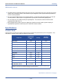
Specifications
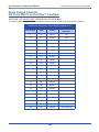
CURRENT DRAW
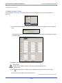
Use this chart to calculate the Amphour requirements of the DX-120 system based upon its configuration. This
information is typically used to apply UPS battery requirements.
Current Draw
(Amps) @ 117
VAC
Quantity
Extended
Total Amps
KSU1 (7201)
0.18A
1
0.18A
KSU2 (7202)
0.17A
1 max.
COM4 (7210)
0.02A
2 max.
DPM8 (7220)
0.01A
4 max.
APM4 (7230)
0.08A
3 max.
MDM (7249)
0.01A
1 max.
AAM (7240)
0.01A
1 max.
7271C
0.02A
1 max.
7270C
0.01A
1 max.
DET (7261-00)
0.016A
80 max.
DSS (7262-00)
0.016A
12 max.
0.02A every 100
ft. of 24AWG
?
Component
Station wire:
per DET, DSS, and IST
Multiply the unit times the quantity installed in the subject application (site) and add the right
column for the total current draw (Amps) @ 117VAC for this site.
Specifications (continued on next page)
- 31 -
OVERVIEW
DX-120 Installation and Maintenance Manual
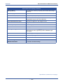
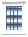
Specifications (continued)
SYSTEM CRITERIA AND CAPACITY
System Criteria and Capacity
Time slots
PCM - 32 time slots x 8 Highways (256 voice channels)
TDM 64 Time Slots (data processing)
Customer database memory protection
300 hours via on-board lithium battery (no charging required)
Ports:
CO/PBX/Centrex Lines
16
Digital Stations
48
Standard Single Line Telephones
16*
*There are 32 total possible digital extensions in this configuration.
DTMF Receivers:
One dedicated per single line telephone port
DTMF Senders:
Unlimited
DTMF signal generation is derived from the core system tone
resource. Tone combinations are available as needed.
Tone Detectors: (used to monitor call
progress tones; Busy Tone, Ring-back
Tone, etc.)
2 (shared for advanced call processing system features; DISA, ECF,
ABR. etc.)
Contacts
1 LBC can be programmed as associated to a CO line or dialed by an
extension to actuate the contact
Conference circuits
8 - 4 party conference circuits
DISA circuits
Any number of CO lines may be programmed for DISA operation.
(AAM required for operation.)
System Attendants
1 Attendant + 1 alternate per tenant group
Tenant Groups
3
UCD/Hunt Groups:
24
Members per group:
24
Group Types:
UCD or Voice Announce
Hunting Method:
Linear, All Ring or Distributed
System Criteria and Capacity (continued on next page)
- 32 -
OVERVIEW
DX-120 Installation and Maintenance Manual
System Criteria and Capacity (continued)
Voice Mail Groups
1 per Tenant (uses 1 UCD Group per VM system)
Members (ports)
24
Integration Method
Digital (ICD Voice) and In-band (for other)
VM message waiting
#96 + station number to turn VM button LED on.
VM control codes
#*96 + station number to turn VM button LED off
Disconnect Digits: 8 digits max.
Subscriber Calling via Intercom: 4 digits max.
Transfers to VM : 4 digits max.
Busy Forward: 4 digits max.
No Answer Forward: 4 digits max.
Direct Call Forward: 4 digits max.
CO Line Recall: 4 digits max.
CO Line Ringing: 4 digits max.
UCD Overflow: 4 digits max.
Record Digits for Voice Recorder function: 4 max.
Delete Digits: 4 digits max.
Suffix for transferred calls: 2 max.
CO line loop current sensing
Interrupt programmable from 50ms to 2500ms.
Paging
8 Internal Page Extension Groups
1 External Page Port
1 Internal All Call
1 System (Internal/External) All Call
Speed Dialing
1000 total bins, dynamically allocated.
200 bins at default allocated for system-wide use.
20 bins at default allocated for extension use (extensions 101-148
only) (50 possible per extension)
16 digits maximum per bin.
Last Number Redial
16 digits per station
Save Number Redial
16 digits per station
User Saved Number (Memo Pad)
20 digits per station
Callback request per station
1
Camp On by a busy station
1
Stations Camped on to a station
1
Stations Camped on to a busy line
1
Message - Executive Notification
6 pre-programmed
1 personal per station
Message - Executive Preprogrammed
6 pre-programmed
1 personal per station
System Criteria and Capacity (continued on next page)
- 33 -
OVERVIEW
DX-120 Installation and Maintenance Manual
System Criteria and Capacity (continued)
Message Waiting
40 simultaneous maximum per system (does not affect VM message
indications)
Name in Display
1 per station, 7 characters max.
Class Of Service (COS)
8 (0-7) per Day, 8 (0-7) per Night
Toll Restriction To/From Tables
100 Tables per tenant, 10 digits per entry, Day and Evening COS
assignable per entry per CO Line and Extension.
Forced Verified Account Codes
600 codes, 2-8 digits max., each assigned a COS
Unverified Account Codes
8 digits max.
Call Pick Up Groups
8 extension groups
Station Lock Password
4-8 digits per extension
CDB Programming Password
8 alphanumeric characters (“________” eight spaces at default);
default password when programming via DET ”########” (eight
pound signs)
System Reminder Alarm
8 time settings per tenant group
Station Alarm
1 per station repeating or one time
Ring Schemes
8
Distinctive Ring Tones
8 per station
External Call Forward
via extension call forward settings
Specifications (continued on next page)
- 34 -
OVERVIEW
DX-120 Installation and Maintenance Manual
Specifications (continued)
ELECTRICAL DATA
Electrical Specifications
AC Power source
Dedicated 117/230vac + 15%, 47-63Hz single phase
Power consumption
1.5A maximum @ 120vac (180 watts)
Power Supply fuse
AC input:
2A 250v
DC output:
1A 125v
Idle Channel Noise
-74 dB
Cross Talk Attenuation
75 dB (@ 1kHz)
Ringing Sensitivity
40v RMS 25 Hz
Ringer Equivalence Number
1.5
CO Line Signaling
DTMF amplitude (-5 dB,-7 dB) +- 2 dB, @ approx. 2 Vpp
Pulse Dialing ratio 60/40 @ 10 PPS
Music source / Background Music
0 dBm at 600 ohm input impedance
Contact rating (Option Module LBC)
1A @ 30VDC
0.5A @ 90VAC 30Hz
1/8th inch phono jack
External Page Port
0 dBm at 600 ohms
1/8th inch phono jack
ENVIRONMENTAL DATA
Environmental Specifications
Operating Temperature
0o to 35o C, 32o to 95o F
Recommended Operating Temperature
70o to 78o F
Storage Temperature
32o to 104o F
Operating Relative Humidity
5% to 90% (non-condensing)
Heat Dissipation (BTU)
300
Specifications (continued on next page)
- 35 -
OVERVIEW
DX-120 Installation and Maintenance Manual
Specifications (continued)
UNIT (COMPONENT) DETAIL
UNIT SPECIFICATIONS
Part Number
Description
Dimensions:
Weight
7200
CPM Central Processor Module
L
W
H
210 mm
138 mm
18 mm
8.25 in.
5.5 in.
.75 in.
0.4Kg
7201P/7202P
KSU1/KSU2
L
W
H
460 mm
270 mm
105 mm
18.4 in.
10.8 in.
4.2 in.
4.0Kg
7210
COM4 Central Office Module – 4 Port
L
W
H
210 mm
138 mm
18 mm
8.25 in.
5.5 in.
.75 in.
0.3Kg
7220
DPM8 Digital Port Module – 8 Port
L
W
H
210 mm
138 mm
18 mm
8.25 in.
5.5 in.
.75 in.
0.28Kg
7221
DPM16 Digital Port Module – 16 Port
L
W
H
210 mm
138 mm
18 mm
8.25 in.
5.5 in.
.75 in.
0.4Kg
7230
APM4 Analog Port Module – 4 Port.
L
W
H
210 mm
138 mm
21 mm
8.25 in.
5.5 in.
.0875 in.
1.2Kg
7240
AAM Automated Attendant Module
L
W
H
140.1 mm
105 mm
2.22 mm
5.515 in.
4.135 in.
.0875 in.
0.09 Kg
7248
408M Standard 4 CO Line x 8 Digital
Extension Module
L
W
H
210 mm
138 mm
18 mm
8.25 in.
5.5 in.
.75 in.
0.4Kg
7249
MDM Modem Module
L
W
H
75.05 mm
55.12 mm
13.33 mm
2.955 in.
2.170 in.
0.525 in.
0.3Kg
7261-00
DET
Digital Executive Telephone
(LCD Speakerphone)
L
W
H
230 mm
182 mm
140 mm
9 in.
7.25 in.
5.5 in.
1.7Kg
7262-00
DSS Console
L
W
H
241 mm
202 mm
93 mm
9.5 in.
8 in.
3.75 in.
1.7Kg
Unit Specifications (continued on next page)
- 36 -
OVERVIEW
DX-120 Installation and Maintenance Manual
UNIT SPECIFICATIONS (continued)
Part Number
Description
Dimensions:
Weight
7270
CO DX HD
L
W
H
210 mm
138 mm
21 mm
8.25 in.
5.5 in.
.0875 in.
0.342Kg
7271C
CO DX FLASH
L
W
H
210 mm
138 mm
21 mm
8.25 in.
5.5 in.
.0875 in.
0.233Kg
7285
ISDN (T1/PRN) Module
L
W
H
210 mm
138 mm
17.4 mm
8.25 in.
5.5 in.
.69 in.
0.184Kg
7290
T1 Module
L
W
H
210 mm
138 mm
17.4 mm
8.25 in.
5.5 in.
.69 in.
0.184Kg
WIRING DATA
Maximum Cable Length
DET (distance measures in linear feet of
cable from KSU to DET)
26 AWG - 255m (850 ft.)
24 AWG - 425m (1416 ft.)
22 AWG - 700m (1983 ft.)
Standard Single Line Telephone (distance measures in linear feet of cable
from KSU to IST)
26 AWG - 195m (650 ft.)
24 AWG - 340m (1133 ft.)
22 AWG - 476m (1586 ft.)
SIGNALING (CENTRAL OFFICE-PSTN) DATA
Dialing Specifications
DTMF Dialing Mode
Frequency deviation:
+ 1%
Rise time:
3ms
Duration of DTMF signal:
programmable 50-150ms (70ms default)
Inter-digit time:
programmable 50-150ms (70ms default)
VM Port DTMF duration:
programmable 60-150ms (120ms default)
VM Port Inter-digit time:
programmable 60-150ms (120ms default)
Pulse Dialing Mode
Pulse dial rate:
10 pulses per second
Pulse Make/Break ratio:
60/40
Specifications (continued on next page)
- 37 -
OVERVIEW
DX-120 Installation and Maintenance Manual
Specifications (continued)
REGULATORY DATA
FCC Registration Numbers
For systems configured for key system operation (each
CO line appears on its own dedicated button).
D6XTAI-40144-KF-T
For systems configured for hybrid operation (CO lines
may be accessed by dial codes and Pool/Loop buttons).
D6XTAI-40145-MF-T
SIGNALING (INTERNAL) DATA
Audible Signals
Signal
Frequency
Cadence
Scheme 0
N/A
Scheme 1
N/A
300ms On, 400ms Off, 300ms On, 4 seconds
Off
Scheme 2
N/A
1 second On, 3 seconds Off
CO Line Ringing:
Scheme 3
1 second On, 3 seconds Off
Scheme 4
follows ring cadence of Ring Scheme selected
Scheme 5
follows ring cadence of Ring Scheme selected
Scheme 6
follows ring cadence of Ring Scheme selected
Scheme 7
-SLT bell-
follows ring cadence of Ring Scheme selected
follows ring cadence of Ring Scheme selected
Distinctive 1
Distinctive 2
Distinctive 3
Distinctive 4
SLT
Intercom Ringing:
Scheme 0
N/A
1 second On, 3 seconds Off
Scheme 1
N/A
1 second On, 3 seconds Off
Scheme 2
N/A
Scheme 3
300ms On, 400ms Off, 300ms On, 4 seconds
Off
Scheme 4
follows ring cadence of Ring Scheme selected
Scheme 5
follows ring cadence of Ring Scheme selected
Scheme 6
follows ring cadence of Ring Scheme selected
Scheme 7
Distinctive 1
-SLT bell-
follows ring cadence of Ring Scheme selected
follows ring cadence of Ring Scheme selected
Distinctive 2
Distinctive 3
Distinctive 4
SLT
Message Wait Callback
follows ring cadence of Ring Scheme selected
Specifications (continued on next page)
- 38 -
OVERVIEW
DX-120 Installation and Maintenance Manual
Specifications (continued)
MTBF (MEAN-TIME BETWEEN FAILURE) DATA
Mean-Time Between Failure Analysis
System Components
Cabinet Assembly
86.0
Power Supply Unit
170.0
CPM
2,915.7
408M
11,407.3
DPM8
3560.8
DPM16
121,654.5
COM4
6,146.5
APM4
6,860.2
MDM
761.0
AAM
2,337.3
T1
318,076.27
ISDN (T1/PRI)
257,340.64
Method:
Use the figures above for each unit installed (or to be installed)
and calculate the total for this system configuration.
Use the total from step 1 in place of the variable “x” in the formula
at the right to calculate MTBF for this system configuration.
- 39 -
(1 ³ )x(109) = MTBF hours
THIS PAGE INTENTIONALLY LEFT BLANK
DX-120 Installation and Maintenance Manual
SECTION 2 - INSTALLATION
INSTALLING THE DX-120
Proper installation of the Vertical DX-120 is essential to assure optimum system operation. You must follow these
procedures to reduce system problems resulting from improper installation and to reduce the potential of
experiencing problems while bringing the DX-120 on-line.
Installation Overview
The following steps provide an overview of the installation process. Details on each of these steps are contained in
the following sections of this chapter. Be sure to read the detailed instructions before installing the DX-120.
A) Plan the installation, including the KSU1 or KSU1 and KSU2 and Main Distribution Frame (MDF) location,
station locations, cable runs, and optional equipment.
B) Assemble the correct tools and supplies: UTP telephony grade cable/wiring, miscellaneous telephony
hardware, 66 blocks, modular wall jacks, etc.)
C) Run the wiring for speakerphones, DSS consoles and analog devices (FAX machines, modems, etc.) from
the MDF to each location.
-
Wiring topology is referred to as “star-wiring” configuration; no cable should loop from one telephone
location to another.
D) Run cable/wiring to any optional equipment, such as external paging equipment, loud bell signaling devices,
music sources, etc.
E) Mount the MDF backboard and attach the terminal blocks on the backboard. Use a dedicated MDF with 66
block wiring field to promote full serviceability of the system and connections using proven techniques.
-
If you route extension cables into the KSU, you have to terminate one cable pair into standard crimping
modular connectors for each cable.
CAUTION
Although you can route the extension cable/wiring directly into the DX-120 KSU1/
KSU2 housing and connect directly to the appropriate interface module (408M,
DPM8, DPM16, APM4, COM4, CPM), Vertical does not recommend this method
since it makes it difficult to service the system.
F) Mount the KSUs on the MDF backboard, using the mounting template provided.
G) Ground the KSU1 (and KSU2 if applicable) to a known “good” earth ground.
H) Install optional expansion modules (COM4, DPM8, DPM16, APM4) inside the KSU as required.
• APM4 is factory installed in KSU1. However, one can be installed in KSU2 via the dedicated cable.
I) Install optional features modules (AAM, 7270C, 7271C, or MDM) inside the KSU as required.
J) Install the telephone instruments and any optional telephone equipment, such as headsets or single line
telephones.
- 41 -
INSTALLING THE DX-120
DX-120 Installation and Maintenance Manual
Site Planning
The first step in site planning is establishing suitable environmental conditions for the system.
A) Place KSU1, and KSU2 if applicable, within 5 feet (1.5 meters) of an isolated, dedicated, 105-125VAC,
57-63Hz, 15A, single-phase commercial power source.
CAUTION
• This must be an isolated, dedicated AC circuit for proper operation.
• Run all three wires (power, neutral, and ground) separately from the
outlet to the breaker panel, without being bonded to any other wire or
circuit.
• Do not plug any other equipment into this outlet.
• To maintain the protection provided by the isolated, dedicated circuit, the
length of the AC power cord limits the distance between the KSU and the
outlet.
• To protect the system from lightning damage or other AC power line
disturbances, install a surge protector.
• Do not use an extension cord.
• Select the KSU location to minimize cable run length. Terminal
equipment connected to the system must not exceed specified limits (see
see “Specifications” ).
• The KSU location should not be exposed to direct sunlight, high
humidity, heat, dust, or strong magnetic fields (such as those generated
by heavy motors, copy machines and some kitchen appliances).
• The DX-120 system must be installed in a climate controlled environment.
This equipment cannot function in environments above 95 degrees
Fahrenheit ambient temperature.
B) The MDF should consist of a 3/4-inch plywood backboard large enough to mount all hardware and
equipment allowing all components ample space for adequate ventilation and servicing. Allow additional
room for external apparatus, if used.
C) For cooling purposes, ample air space (at least four inches on the top, bottom, left and right sides) must be
provided for the KSU.
D) SMDR/SMDA output devices must be placed within 50 feet (15 meters) of the KSU (limited by RS-232C
standard wiring practices).
E) The equipment should be located in a climate-controlled room adhering to the environmental specifications
listed in see “Environmental Data” .
CAUTION
• When installing the KSU and station instruments, allow a sufficient
margin for error in case of air conditioning failure, routine maintenance,
plant shutdown, etc.
• As a general rule, if conditions are suitable for office personnel, they are
also suitable for KSU and terminal equipment operation.
• A properly controlled environment will help to extend the operating life of
the equipment.
Site Planning (continued on next page)
- 42 -
INSTALLING THE DX-120
DX-120 Installation and Maintenance Manual
Site Planning (continued)
• The following statements are from UL 1459, a product safety specification governing telephone equipment:
-
Never install telephone wiring during a lightning storm.
-
Never install telephone jacks in wet locations unless the jack is specifically designed for wet locations.
-
Never touch non-insulated telephone wires or terminals unless the telephone line has been disconnected
at the network’s interface.
-
Use caution when installing or modifying telephone lines.
CAUTION
Per Underwriters Laboratories regulation 1950, TNV wiring to outside plant leads (e.g. central
office trunk wiring) must be 26 AWG gauge minimum.
Tools and Supplies
Assemble the correct supplies and tools to install the Vertical DX-120.
• Use UTP (Unshielded, Twisted-Pair) three or four pair (recommended) cable to run from the MDF to all
extension terminals (DETs, DSS consoles, and analog devices). DETs only need one twisted pair to operate.
Additional pairs are always recommended to allow for future potential uses.
• Six conductor modular jack assemblies for all station instruments (recommended).
• Standard punch-down terminal blocks (66M1-50 type) as required.
• Four or six conductor crimping modular plug assemblies for each port interface.
• AC voltage surge/spike protector.
• Standard telephone hand tools and mounting hardware for the KSU(s), MDF backboard, punch-down terminal
block(s), modular jack assemblies for CO lines, etc.
Preparing the Main Distribution Frame
The MDF is the point at which the KSU, terminal equipment, CO lines, and miscellaneous equipment connect to
one another. It is extremely important that you make the connections carefully and accurately.
ASSEMBLING THE MDF
Follow these steps to assemble the MDF.
1) Mount a sufficiently sized, 3/4-inch plywood backboard at the proper location to use as the MDF
termination and equipment mounting board.
2) Plan the layout of all required MDF components allowing for expansion. This may include: KSU1,
KSU2, 66M1-50 termination blocks, cable fastening hardware, and miscellaneous third-party
communications equipment (paging equipment, etc.).
3) Locate the Telco-provided CO/Centrex lines at the DEMARC (Demarcation) and extend them to the
MDF location.
4) Locate a suitable, known-good earth ground preferably within 10 feet of the MDF and route a
#10AWG grounding wiring from the point of grounding to the MDF for connection to the KSU.
5) Install all telephone cabling and route to the MDF location for termination.
6) Mount all equipment and termination hardware as required to interconnect terminal devices and KSU
modules.
Preparing the Main Distribution Frame (continued on next page)
- 43 -
INSTALLING THE DX-120
DX-120 Installation and Maintenance Manual
Preparing the Main Distribution Frame (continued)
KSU COMPONENTS AND INSTALLATION
• KSU1
-
one mounting template
-
standard 408M (module) equipped with eight digital extension ports, four CO line ports, and one CO line
PFT (Power Failure Transfer) port
-
standard CPM
-
standard APM4
-
system installation, maintenance, and programming manuals and system installation quick reference
guide.
• KSU2
-
one mounting template
-
standard expansion cabinet 408E (module) equipped with 8 digital extension ports, four CO line ports,
and one CO line PFT port.
IMPORTANT!
Open the cartons and verify that all items are complete and undamaged.
Remove all packing material and store for future use in the event that return
shipment is required.
MOUNTING THE KSU
1) Select a suitable location for the KSU1 considering that the expansion (KSU2) may be installed at the
same time or sometime in the future.
• KSU1 and KSU2 may be mounted such that they are side-by-side or mounted one above the other.
2) Using the mounting template as a guide, mark the two mounting screws locations on the MDF
backboard.
3) Pre-drill two screw holes and install the two, pan-head No. 10 screws (supplied) into the backboard
with a regular screwdriver.
• The screw heads should protrude about 1/4-inch from the backboard plywood surface.
4) Lift the KSU over the two screws, allowing the screws to extend into the KSU slotted mounting holes.
• As the KSU is allowed to rest in place on the mounting screws it will slip over the screw shanks until
the top of the slot is reached.
• Properly installed, the KSU power transformer (where the KSU AC power cord is located) is
positioned in the upper left corner.
• The power switch and power/heartbeat LED are positioned at the left side of the KSU toward the
bottom.
CAUTION
It is very important that you mount the KSU correctly to allow proper power supply heat
dissipation. KSU1 and KSU2 must be wall mounted only in order to prevent the build up of
heat in and around the system.
Mounting the KSU (continued on next page)
- 44 -
INSTALLING THE DX-120
DX-120 Installation and Maintenance Manual
Mounting the KSU (continued)
5) Extend the earth ground #10 wire into the KSU opening at the lower left corner of the KSU.
6) Terminate the grounding wire onto the ground lug provided there.
• The two steps above ground the KSU.
Ground Lug
- 45 -
INSTALLING THE DX-120
DX-120 Installation and Maintenance Manual
KSU Wiring
The 408M/E, APM4, COM4, and DPM8 are equipped with RJ-11 modular jacks for each of the interfaced ports.
This connection scheme allows for two methods of installation. The first method (traditional “MDF”) is
recommended whenever possible to allow for maximum serviceability.
CAUTION
System power must be OFF before you plug in the station cable or while servicing port
connections at the punch-down block (66M1-50). Although each port is over-current
protected, unnecessary shorting should be avoided.
EXTENDING PORTS TO THE MDF
• Whenever you extend the various ports of the DX-120 to the MDF, you must extend modular-ended cables
from the KSU module port to the MDF connection block. You have many choices when completing these
connections; it is left to the your discretion to use the most suitable industry-standard wiring practice for the
particular installation.
CAUTION
Use a quality crimping tool to fasten the modular connector to the cable pair when using
field-crimped modular connectors. Use of an inferior crimping tool can lead to bad
connections.
• Many third-party vendor products are available to aid in this installation procedure. The following examples
are readily available at communications equipment / accessories supply houses. Although this example
denotes product of The Siemon Company®, you are urged to investigate the various products available and
make decisions for use based on your own assessment. Vertical is not responsible for the performance of
any product provided by a third-party (outside) vendor.
EXAMPLE
The examples in the following chart are 25 pair (UTP), USOC, 24 AWG cables
pre-fitted with modular connectors on one end of the cable, and a male or female
AMP® type connectors on the other end for termination on a specially equipped,
66-block with mating AMP® type connector.
The Siemon Company® Hydra Cable Assemblies
Product Number
Length (feet)
Wiring Scheme - End 1
HYD-F-24U1-03
3
25-Pair, Female
HYD-F-24U1-07
7
25-Pair, Female
HYD-F-24U1-10
10
25-Pair, Female
HYD-M-24U1-03
3
25-Pair, Male
HYD-M-24U1-07
7
25-Pair, Male
HYD-M-24U1-10
10
25-Pair, Male
• When you are finished with the KSU wiring, you can individually isolate each port of the DX-120 system for
independent maintenance needs. Terminate the wiring in place onto a 66M1-50 – connector block. Extend
ports from this connector block to station cables using standard jumper wire.
- 46 -
INSTALLING THE DX-120
DX-120 Installation and Maintenance Manual
NO MDF
IMPORTANT!
Although this method initially appears to be convenient and more cost-effective, thre is an
inherent lack of serviceability. Therefore, Vertical does not recommend this method of installation.
Since the Vertical DX-120 is equipped with RJ-11 interfaces for all port connections*, it is possible to route station
cables into the KSU directly without use of 66M1-50 connector blocks. Using quality modular connectors and
crimping tool, connect each terminal cable directly to the port required.
Regardless of the method used, route the station / MDF cables out of the KSU through the opening at the lower left
of the KSU housing. A cable restraint clamp is provided which you can use to secure cables exiting the KSU.
cable restraint
clamp
*This does not include DPM16.
- 47 -
INSTALLING THE DX-120
DX-120 Installation and Maintenance Manual
Typical MDF Installation
The following example install illustrates a two-cabinet installation using the MDF installation method.
Dedicated AC outlet
(i.e., the dedicated
outlet must have no
other equipment
connected to it on
this circuit breaker).
“Station” cables
from telephones
DX-120
KSU 1
DX-120
KSU 2
#10 AMG
Ground
Paging
Equipment
(or other
third-party
equipment)
66M1-50 Blocks
Ancillary
Equipment
(paging, music
sources, etc.)
66M1-50 Blocks
KSU
Termination
66M1-50 Blocks
“Station” Phone
Cable
Terminations
66M1-50
• The 66M1-50 is split into a left and right half for
termination wiring.
• Each row conducts between the two left
columns and the two right columns. This is the
source of the term “Split 50”
• Be sure to treminate cable pairs from the KSU
and from telephone locations on outer column
pins (one lead only per pin).
IMPORTANT!
NEVER terminate two wires on one pin!
This is refered to as “double-punching”
and causes poor connection of wires on
the terminal.
NOTE
When used with “Bridging Clips”, the Split
50 Block can be used to isolate trouble in
wiring.
- 48 -
INSTALLING THE DX-120
DX-120 Installation and Maintenance Manual
KSU Components
KSU1 408M AND KSU2 408E
The 408M module is installed at the factory into KSU1. Although this module has the same port configuration as
the 408E, they are not interchangeable. Each 408M and 408E is equipped with four CO line ports, one power
failure port, and eight digital extension Ports. See the following diagram to locate the various ports provided on the
408M/E.
The 408M/E is also the interface point for the various add-on modules of the DX-120 system. All peripheral
modules connect to the DX-120 via the 408M/E. See the following diagram for a reference to the various interface
connectors.
APM4 Ribbon Connector
COM4 Ribbon Connector
408M: CPM Ribbon Cable
408E: CPM Connector Cable
(aprox. 1 meter long to extend out of KSU2
into KSU1)
Voice Processor Power
Connector
Extension Expansion
module connectors
DPM8 or APM4
8 digital extension ports
KSU1: 101-108
KSU2: 141-148
Power Failure
Transfer Port
KSU1: 800
KSU2: 808
4 CO line circuits
KSU1: 800-803
KSU2: 808-811
KSU Components (continued on next page)
- 49 -
INSTALLING THE DX-120
DX-120 Installation and Maintenance Manual
KSU Components (continued)
REPLACING A 408M OR 408E
Occasionally, when instructed to do so by a Vertical technical support representative, you may have to remove a
408M or 408E and replace it in the field. To do so, use the following the steps.
1) Be sure that the entire system is turned off.
2) Remove the KSU cover (four screws at each corner).
3) Install a static discharge wrist strap on your bare wrist, and adjust it for a snug fit.
CAUTION
Be sure that the strap is touching bare skin and is not isolated by clothing.
4) Connect the wrist strap cord between the wrist strap and an AC or earth ground.
5) Connect a static discharge wrist strap to a suitable earth ground.
CAUTION
Circuit boards are susceptible to damage caused by electrostatic
discharge. You must keep this in mind as you handle the circuit boards.
For additional information, see Vertical publication IMI01-005, Handling of
Electrostatically Sensitive Components.
6) Remove all circuit modules from the KSU cabinet.
NOTE
• All modules are fastened in place using standoff hardware, therefore, be sure
to reconstruct these stand off placements when you re-install the various
modules.
• APM4 modules must be installed using 2.5 cm (nickel) standoffs.
7) Install the replacement 408M/E using the 1.5cm (brass) standoffs removed from the original.
8) Install all other remaining modules in the order that they were removed.
• Be sure to connect them to the appropriate 408M/E connector.
9) Reconnect CO line and station cabling connections as required.
CAUTION
The FCC requires that wiring of CO lines into a KSU be separated from
wiring of station apparatus into a KSU. Therefore you must use separate
cables for wiring stations and CO lines.
10) Replace the KSU cover and secure with cover screws.
11) Restore KSU power when all wiring is complete.
- 50 -
INSTALLING THE DX-120
DX-120 Installation and Maintenance Manual
KSU Components (continued)
KSU ASSEMBLY – ADD-ON MODULES
• Whenever you expand the DX-120 system, you install a module into one of the KSU cabinets.
• Modules are connected to the various connectors on the 408M/E.
• Modules are mounted using standoff posts.
- Two standoff post sizes are used in the DX-120.
- The APM4 modules must be installed using the 2.5 cm (nickel) standoffs.
- All other modules use the 1.5 cm (brass) standoffs.
IMPORTANT!
Proper use of standoff is imperative to assure proper system operation.
408M Connector
408E Connector to KSU2
VM/AAM Connector
T1 or ISDN (T1/PRI)
Connector
MDM Connectors
AAM Connector
CPM
Normal/Cold
Start Strap
SLOT 4
DPM8 (J3 Connector)
SLOT 3
DPM8 (J2 Connector)
SLOT 2 APM4 (Dedicated Cable)
SLOT 1
DPM8 on Board
COM4 or T1 OR ISDN (T1/PRI)
(Dedicated Cable)
408 M/E (KSU1/KSU2)
COM4 On Board
SLOT 5
SLOT 1
KSU Components (continued on next page)
- 51 -
INSTALLING THE DX-120
DX-120 Installation and Maintenance Manual
KSU Components (continued)
ADDING A DPM8
You can add two DPM8 modules to each KSU of the DX-120 system. These modules expand the DX-120 system
capacity to a maximum of 24 digital ports in each KSU, for a total of 48 total digital ports.
To install a DPM8, connection to the 408M/E via the Extension Expansion module connectors J2 and J3. These
connectors have the logical system address of SLOT 2 and SLOT 3 in both cabinet 1 (KSU1-408M) and cabinet 2
(KSU2-408E).
NOTE
You can connect both APM4 and DPM8 modules to the system via these two
connectors. Install the DPM8 using four 2.0 cm brass color standoffs included
with the DPM8 module.
DPM8 Extension Number Matrix Per Installed Location
KSU Connector Used
J2 Extension Expansion
J3 Extension Expansion
Extension Numbers in KSU1
Extension Numbers in KSU2
109,110,111,112,
113,114,115,116
173, 174, 175, 176,
125, 126, 127, 128,
129, 130, 131, 132
189, 190, 191, 192,
177, 178, 179, 180
193, 194, 195, 196
INSTALLING THE DPM8
1) Be sure that the entire system is turned off.
2) Remove the KSU cover (four screws at each corner).
3) Install a static discharge wrist strap on your bare wrist, and adjust it for a snug fit.
CAUTION
Be sure that the strap is touching bare skin and is not isolated by clothing.
4) Connect the wrist strap cord between the wrist strap and an AC or earth ground.
5) Connect a static discharge wrist strap to a suitable earth ground.
CAUTION
Circuit boards are susceptible to damage caused by electrostatic
discharge. You must keep this in mind as you handle the circuit boards.
For additional information, see Vertical publication IMI01-005, Handling of
Electrostatically Sensitive Components.
6) Remove the DPM8 module from the packaging and locate the four brass-color standoffs packaged
with the module.
Installing the DPM8 (continued on next page)
- 52 -
INSTALLING THE DX-120
DX-120 Installation and Maintenance Manual
Installing the DPM8 (continued)
7) Position the DPM8 over the left-hand side of the 408M/E and any other extension modules already
installed.
NOTE
When installing DPM8 modules, Vertical recommends that you install them
closest to the 408M/E. An APM4 module is always factory-installed in KSU1. In
addition, a second APM4 can be installed in KSU2 (see page 54). Therefore,
before installing the DMP8 you must move any installed APM4 module outward
(toward cabinet cover) and install the add-on DPM8 first, then re-install the APM4.
In the KSU extension modules are always installed on the left-hand side.
8) Use the four brass-color standoffs supplied with the DPM8 to secure the DPM8 in position.
9) Connect the DPM8 ribbon cable to the 408M Extension Expansion Module Connector closest
to the DPM8.
HINT
Press firmly (but not forcefully) on the connector to secure a good connection.
10) Make connections to the eight (8) digital ports as required.
CAUTION
The FCC requires that wiring of CO lines into a KSU be separated from
wiring of station apparatus into a KSU. Therefore you must use separate
cables for wiring stations and CO lines.
11) Replace the KSU cover and secure with cover screws.
12) Restore KSU power.
- 53 -
INSTALLING THE DX-120
DX-120 Installation and Maintenance Manual
Adding an APM4
One APM4 is factory-installed in KSU1. However, you can add an second APM4 to the KSU2 (via the dedicated
cable). With the 2 APM4s, the DX-120 system capacity is eight analog station ports (4 in each KSU). The APM4s
utilize four 2.5 cm (nickel) standoffs.
APM4
408M
APM4
Extension Number Matrix Per Installed Location
KSU Connector used
APM4 Connector
(SLOT 4)
Extension numbers in
KSU1
Extension Numbers in
KSU2
Notes
149,150,151,152
153,154,155,156
KSU1 analog ports are standard
Adding an APM4 (continued on next page)
- 54 -
INSTALLING THE DX-120
DX-120 Installation and Maintenance Manual
Adding an APM4 (continued)
INSTALLING THE APM4 IN KSU2
1) Be sure that the entire system is turned off.
2) Remove the KSU2 cover (four screws at each corner).
3) Install a static discharge wrist strap on your bare wrist, and adjust it for a snug fit.
CAUTION
Be sure that the strap is touching bare skin and is not isolated by clothing.
4) Connect the wrist strap cord between the wrist strap and an AC or earth ground.
5) Connect a static discharge wrist strap to a suitable earth ground.
CAUTION
Circuit boards are susceptible to damage caused by electrostatic
discharge. You must keep this in mind as you handle the circuit boards.
For additional information, see Vertical publication IMI01-005, Handling of
Electrostatically Sensitive Components.
6) Remove the APM4 module from the packaging and locate the four nickel-color standoffs packaged
with the module.
7) Position the APM4 over the left-hand side of the KSU2 408M/E and any other extension modules
already installed.
NOTE
In the KSU2, extension modules are always installed on the left-hand side.
8) Use the four nickel-color standoffs supplied with the APM4 to secure the APM4 in position.
9) Connect the dedicated APM4 ribbon cable from the 408E to the APM4 module.
IMPORTANT!
Do not use any other connector other than the dedicated cable as provided.
HINT
Press firmly (but not forcefully) on the connector to secure a good connection.
10) Make cable/wiring connections to the 4 analog ports as required.
CAUTION
The FCC requires that wiring of CO lines into a KSU be separated from
wiring of station apparatus into a KSU. Therefore you must use separate
cables for wiring stations and CO lines.
11) Replace the KSU2 cover and secure with cover screws.
12) Restore power.
- 55 -
INSTALLING THE DX-120
DX-120 Installation and Maintenance Manual
Adding a COM4
You can add one COM4 to KSU1 and one COM4 to the KSU2. These modules expand the DX-120 system loop
start CO line interface capacity to a maximum of eight loop start CO line ports in each KSU (16 total loop startCO
line ports when used in KSU 1 & 2).
• When adding a COM4 to either KSU, connect to the 408M/E via the COM4 module ribbon cable.
-
This ribbon cable has the logical system address of SLOT 5 in both cabinet 1 (KSU1-408M) and cabinet
2 (KSU2-408E).
• COM4 modules are installed using four 2.0 cm (brass) standoffs.
• Always install the COM4 module beneath the CPM module (in KSU1) by first removing the CPM, installing the
COM4, and then re-installing the CPM. This is required whenever you install the In-Skin Voice Processor.
CO Line Directory Number Matrix Per Installed Location
408M in KSU1 - SLOT 1
COM4 in KSU1 - SLOT 5
408E in KSU2 - SLOT 1
COM4 in KSU2 - SLOT 5
800, 801, 802, 803
804, 805, 806, 807
808, 809, 810, 811
812, 813, 814, 815
Adding a COM4 (continued on next page)
- 56 -
INSTALLING THE DX-120
DX-120 Installation and Maintenance Manual
Adding a COM4 (continued)
INSTALLING THE COM4
1) Be sure that the entire system is turned off.
2) Remove the KSU cover (four screws at each corner).
3) Install a static discharge wrist strap on your bare wrist, and adjust it for a snug fit.
CAUTION
Be sure that the strap is touching bare skin and is not isolated by clothing.
4) Connect the wrist strap cord between the wrist strap and an AC or earth ground.
5) Connect a static discharge wrist strap to a suitable earth ground.
CAUTION
Circuit boards are susceptible to damage caused by electrostatic
discharge. You must keep this in mind as you handle the circuit boards.
For additional information, see Vertical publication IMI01-005, Handling of
Electrostatically Sensitive Components.
IMPORTANT!
Vertical recommends installing the COM4 closest to the 408M/E. This means
you must temporarily remove the CPM and then reposition the CPM above the
COM4 once you have installed the COM4 (in KSU1).
For KSU2 installation skip step 6.
6) Remove the installed CPM by removing the four brass standoffs used to secure the board, retaining
these standoffs for later use.
7) Remove the ribbon cable that connects the CPM to the 408M then set it aside.
8) Remove the COM4 module from the packaging and locate the four brass-color standoffs packaged
with the module.
9) Position the COM4 over the 408M/E (right-hand side) where you just removed the CPM (KSU1).
10) Use the four brass-color standoffs supplied with the COM4 to secure the COM4 in position.
11) Connect the COM4 ribbon cable from the 408M/E to the COM4 connector.
HINT
Press firmly (but not forcefully) on the connector to secure a good connection.
Installing the COM4(continued on next page)
- 57 -
INSTALLING THE DX-120
DX-120 Installation and Maintenance Manual
Installing the COM4(continued)
For KSU2 installation, skip step 12 and proceed to step 13.
12) Reposition the CPM over the installed COM4 and secure using the four brass-color standoffs
previously removed (see page 57).
13) Make cable/wiring connections to the 4 CO line ports as required.
CAUTION
The FCC requires that wiring of CO lines into a KSU be separated from
wiring of station apparatus into a KSU. Therefore you must use separate
cables for wiring stations and CO lines.
14) Replace the KSU cover and secure with cover screws.
15) Restore KSU power.
Adding an MDM
You can add one MDM to KSU1. The MDM allows you to remotely access to the DX-120 database programming
and maintenance functions using PC-DBA.
NOTE
The MDM does not provide access to the DX-120 In-Skin Voice Mail/AA.
• At default the MDM directory number is 100.
-
To establish a connection to the MDM remotely, call into the system where the MDM is installed from the
remote site using PC-DBA.
-
Ask to be transferred to extension 100.
-
When you hear the modem tone, initiate any required keystrokes to link the modems.
-
Then proceed with usual PC-DBA connection routines.
NOTE:
If you are using In-skin voicemail or AA a manual transfer is not necessary.
-
Install the MDM onto designated connectors located on the CPM.
Adding an MDM (continued on next page)
- 58 -
INSTALLING THE DX-120
DX-120 Installation and Maintenance Manual
Adding an MDM (continued)
INSTALLING THE MDM
1) Be sure that the entire system is turned off.
2) Remove the KSU cover (four screws at each corner).
3) Install a static discharge wrist strap on your bare wrist, and adjust it for a snug fit.
CAUTION
Be sure that the strap is touching bare skin and is not isolated by clothing.
4) Connect the wrist strap cord between the wrist strap and an AC or earth ground.
5) Connect a static discharge wrist strap to a suitable earth ground.
CAUTION
Circuit boards are susceptible to damage caused by electrostatic
discharge. You must keep this in mind as you handle the circuit boards.
For additional information, see Vertical publication IMI01-005, Handling of
Electrostatically Sensitive Components.
6) Locate the CPM at the right-hand side of KSU1, above the 408M (and COM4 if installed).
7) Position the MDM over the CPM-MDM connectors as shown below.
MDM
CPM
HINT
Press firmly (but not forcefully) on the MDM to secure a good connection into the
CPM-MDM connectors.
8) Replace the KSU cover and secure with cover screws.
9) Restore KSU power.
- 59 -
INSTALLING THE DX-120
DX-120 Installation and Maintenance Manual
Adding an AAM
You can add one AAM to the KSU1. The AA Module adds automated attendant functionality to the DX-120 system
with 10 integrated announcements. The AAM does not provide voice mail functions.
HINT
For more information on how to program the AAM and its announcements, refer
to the DX-120 Technical Manual, Volume II, Programming.
INSTALLING THE AAM
1) Be sure that the entire system is turned off.
2) Remove the KSU cover (four screws at each corner).
3) Install a static discharge wrist strap on your bare wrist, and adjust it for a snug fit.
CAUTION
Be sure that the strap is touching bare skin and is not isolated by clothing.
4) Connect the wrist strap cord between the wrist strap and an AC or earth ground.
5) Connect a static discharge wrist strap to a suitable earth ground.
CAUTION
Circuit boards are susceptible to damage caused by electrostatic discharge.
You must keep this in mind as you handle the circuit boards. For additional
information, see Vertical publication IMI01-005, Handling of Electrostatically
Sensitive Components.
6) Locate the CPM at the right-hand side of KSU1 above the 408M (and COM4 if installed).
7) Position the AAM over the CPM-AAM connectors as shown below.
AA
CPM
HINT
Press firmly (but not forcefully) on the AAM to secure a good connection into the
CPM-AAM connectors.
8) Replace KSU cover and secure with cover screws.
9) Restore KSU power.
- 60 -
INSTALLING THE DX-120
DX-120 Installation and Maintenance Manual
Adding a KSU2 Second Cabinet
You can add one KSU2 to a KSU1. The KSU2 adds:
• eight digital DX-120 extension ports
• four CO line ports
• one Power Failure Transfer port
• Extension expansion connectors for two additional DPM8s or one APM4
• Dedicated ribbon cable for one APM4
• Dedicated ribbon cable for one COM4
INSTALLING THE KSU2 (CONNECTING THE KSU2 TO THE KSU1)
1) Be sure that the entire system is turned off.
2) Remove the cover from both the KSU 1 and KSU 2 (four screws at each corner).
3) Install a static discharge wrist strap on your bare wrist, and adjust it for a snug fit.
CAUTION
Be sure that the strap is touching bare skin and is not isolated by clothing.
4) Connect the wrist strap cord between the wrist strap and an AC or earth ground.
5) Connect a static discharge wrist strap to a suitable earth ground.
CAUTION
Circuit boards are susceptible to damage caused by electrostatic discharge.
You must keep this in mind as you handle the circuit boards. For additional
information, see Vertical publication IMI01-005, Handling of Electrostatically
Sensitive Components.
6) Locate the long cable attached to the 408E of KSU2, and route it out of the KSU2 cabinet into the
KSU1 cabinet so you can connect it to the CPM.
7) Locate the CPM at the right-hand side of KSU1 above the 408M (and COM4 if installed).
Installing the KSU2 (continued on next page)
- 61 -
INSTALLING THE DX-120
DX-120 Installation and Maintenance Manual
Installing the KSU2 (continued)
8) Position the KSU2 connection cable over the CPM-“2nd Cabinet Connector” as shown below.
2nd Cabinet Connector
Cable from KSU2-408E
CPM
HINT
Press firmly (but not forcefully) on the KSU2-Cable connector to secure a good
connection into the CPM-2nd Cabinet Connector.
9) Replace the KSU cover and secure with cover screws.
10) Restore KSU power by powering both KSU cabinets at the same time.
11) Flip both cabinet power switches to the “ON” position simultaneously.
CAUTION
You must turn on both cabinets at the same time. Failure to do so can
result in damage to the KSU1 and potentially the KSU2.
- 62 -
INSTALLING THE DX-120
DX-120 Installation and Maintenance Manual
Adding a Music Source
You can connect two sources of music to the CPM for use with the Music On Hold and Background Music features.
CPM
MC1 & MC2 external music source
Connectors
HINT
A third option is to use an internal musical tune or tone can be used for callers on
hold. When this option is used, the MC1 connector is not used.
SELECTING INTERNAL MUSIC TUNE FOR MUSIC CHANNEL MC1
1) Be sure that the entire system is turned off.
2) Remove the KSU 1 cover (four screws at each corner).
3) Install a static discharge wrist strap on your bare wrist, and adjust it for a snug fit.
CAUTION
Be sure that the strap is touching bare skin and is not isolated by clothing.
4) Connect the wrist strap cord between the wrist strap and an AC or earth ground.
5) Connect a static discharge wrist strap to a suitable earth ground.
CAUTION
Circuit boards are susceptible to damage caused by electrostatic
discharge. You must keep this in mind as you handle the circuit boards.
For additional information, see Vertical publication IMI01-005, Handling of
Electrostatically Sensitive Components.
6) Locate the CPM and “MUSIC” option strap.
7) Move the “MUSIC” option strap (JPC1) from the “EXT” (factory position) to the “INT” position.
Adding a Music Source (continued on next page)
- 63 -
INSTALLING THE DX-120
DX-120 Installation and Maintenance Manual
Adding a Music Source (continued)
INSTALLING EXTERNAL MUSIC SOURCE TO
MC1/MC2/BOTH
1) Be sure that the entire system is turned off.
2) Remove the KSU 1 cover (four screws at each corner).
3) Install a static discharge wrist strap on your bare wrist, and adjust it for a snug fit.
CAUTION
Be sure that the strap is touching bare skin and is not isolated by clothing.
4) Connect the wrist strap cord between the wrist strap and an AC or earth ground.
5) Connect a static discharge wrist strap to a suitable earth ground.
CAUTION
6.Circuit boards are susceptible to damage caused by electrostatic discharge. You must
keep this in mind as you handle the circuit boards. For additional information, see Vertical
publication IMI01-005, Handling of Electrostatically Sensitive Components.
6) Locate the CPM and the “MUSIC” option strap.
7) Make sure that the “MUSIC” option strap is in the “EXT” position. (Required for external source to
operate on MC1.)
8) Locate CPM the “MC1” and “MC2” connector jacks on the CPM.
9) Connect the output of the external music source to the appropriate MC1 or 2 connector
HINT
• At default MC1 is used for Music On Hold.
• This is easily accomplished using a prefabricated mini-plug to mini-plug cable
available at Radio Shack.
10) Adjust the music volume level at the external music source.
HINT
When adjusting the music for Music On Hold:
• Place a call into the system on one of the CO Lines so that the external music
source is heard by the calling party (you).
• Adjust the volume level of the external music source until a desirable level is
reached.
• Background Music is then adjusted at the telephone using the instrument
volume control.
- 64 -
INSTALLING THE DX-120
DX-120 Installation and Maintenance Manual
Adding an External Pager
One port is provided at the CPM of the DX-120 system for use with external paging system apparatus.
• When DX-120 users dial the external pager code (“777” at default) or dial the Tenant Group All Page code
(“400” at default), voice announcements can be made over the external paging equipment.
External “Page” connector
(goes to external amplifier)
• The DX-120 External Page port does not provide any amplification. Interface at the amplifier should be
matched to approximately 600 ohms for the best performance.
EXTERNAL PAGER INSTALLATION PROCEDURE
1) Be sure that the entire system is turned off.
2) Remove the KSU 1 cover (four screws at each corner).
3) Install a static discharge wrist strap on your bare wrist, and adjust it for a snug fit.
CAUTION
Be sure that the strap is touching bare skin and is not isolated by clothing.
4) Connect the wrist strap cord between the wrist strap and an AC or earth ground.
5) Connect a static discharge wrist strap to a suitable earth ground.
CAUTION
7.Circuit boards are susceptible to damage caused by electrostatic discharge. You must
keep this in mind as you handle the circuit boards. For additional information, see Vertical
publication IMI01-005, Handling of Electrostatically Sensitive Components.
6) Locate the CPM and “PAGE” connector jack on the CPM.
7) Using an eighth-inch mini plug, connect the DX-120 Page port to the external amplifier input.
8) Adjust the voice volume level at the external paging amplifier.
HINT
When adjusting the volume level:
• Dial access to the External Pager port at any DX-120 telephone (“777”).
• Adjust the volume control associated to the amplifier input selected for this
purpose.
- 65 -
INSTALLING THE DX-120
DX-120 Installation and Maintenance Manual
Add a Loud Bell Control or Gate Control
One “dry-connection” is provided at the CPM of the DX-120 system for use with external ringing devices or door
opening apparatus. The DX-120 can be programmed to activate the dry contact whenever certain CO lines ring or
whenever the LBC code is dialed to actuate a door opener.
“BELL” control connector (wires to
bell and power supply)
INSTALLING A LOUD BELL
1) Be sure that the entire system is turned off.
2) Remove the KSU 1 cover (four screws at each corner).
3) Install a static discharge wrist strap on your bare wrist, and adjust it for a snug fit.
CAUTION
Be sure that the strap is touching bare skin and is not isolated by clothing.
4) Connect the wrist strap cord between the wrist strap and an AC or earth ground.
5) Connect a static discharge wrist strap to a suitable earth ground.
CAUTION
Circuit boards are susceptible to damage caused by electrostatic
discharge. You must keep this in mind as you handle the circuit boards.
For additional information, see Vertical publication IMI01-005, Handling of
Electrostatically Sensitive Components.
6) Locate the CPM and “BELL” connector jack on the CPM.
7) Wire the DX-120 BELL contact in series with an external 24vdc power supply and 24vdc bell or
ringing device.
CAUTION
Use only 24v or less voltage supply and Direct Current (dc).
8) Program LBC operation for CO line ringing according to CO line group assignments.
HINT
For more information refer to the DX-120 Technical Manual, Volume II,
Programming.
Add a Loud Bell or Gate Control (continued on next page)
- 66 -
INSTALLING THE DX-120
DX-120 Installation and Maintenance Manual
Add a Loud Bell or Gate Control (continued)
INSTALLING A GATE OR DOOR CONTROL
1) Be sure that the entire system is turned off.
2) Remove the KSU 1 cover (four screws at each corner).
3) Install a static discharge wrist strap on your bare wrist, and adjust it for a snug fit.
CAUTION
Be sure that the strap is touching bare skin and is not isolated by clothing.
4) Connect the wrist strap cord between the wrist strap and an AC or earth ground.
5) Connect a static discharge wrist strap to a suitable earth ground.
CAUTION
Circuit boards are susceptible to damage caused by electrostatic
discharge. You must keep this in mind as you handle the circuit boards.
For additional information, see Vertical publication IMI01-005, Handling of
Electrostatically Sensitive Components.
6) Locate the CPM and “BELL” connector jack on the CPM.
7) Wire the DX-120 BELL contact in series with an external 24vdc power supply and 24vdc door opening
device.
CAUTION
Use only 24v or less voltage supply and Direct Current (dc).
8) Program LBC operation for External Page operation.
9) Dial the External Page code to activate the gate/door.
HINT
• The External Page code can be programmed onto an available Flexible
Feature Button.
• For more information refer to the DX-120 Technical Manual, Volume II,
Programming.
- 67 -
INSTALLING THE DX-120
DX-120 Installation and Maintenance Manual
Adding a DPM16 (Digital Port Module – 16 port)
• Two DPM16 (Digital Port Module, 16-port - i.e., 16 digital phones) modules can be added to each KSU of the
DX-120 system.
• These modules expand the DX-120 system extension capacity to a maximum of 40 digital ports in each KSU
(80 total digital ports).
• DPM16’s are installed by connection to the 408M via the Extension Expansion module connectors (“J2”and
“J3.”)
• The DPM16 board has eight RJ-12 jacks.
• Each RJ-12 jack has four wires so you plug two phones into each jack.
• You cannot do a Off-Hook Voice Announce (OHVA) to a phone that is plugged into the DPM16. However, you
can do a OHVA from a phone that is plugged into a DPM16 board.
INSTALLING A DPM16
1) Be sure that the entire system is turned off.
2) Remove the KSU cover (four screws at each corner).
3) Install a static discharge wrist strap on your bare wrist, and adjust it for a snug fit.
CAUTION
Be sure that the strap is touching bare skin and is not isolated by clothing.
4) Connect the wrist strap cord between the wrist strap and an AC or earth ground.
5) Connect a static discharge wrist strap to a suitable earth ground.
CAUTION
Circuit boards are susceptible to damage caused by electrostatic
discharge. You must keep this in mind as you handle the circuit boards.
For additional information, see Vertical publication IMI01-005, Handling of
Electrostatically Sensitive Components.
6) Remove the DPM16 module from the packaging and locate the four brass-color standoffs packaged
with the module.
7) Position the DPM16 over the left-hand side of the 408M/E and any other extension modules already
installed.
NOTE
When installing DPM16 modules, Vertical recommends that you install them
closest to the 408M/E. An APM4 module is always factory-installed in KSU1. In
addition, a second APM4 can be installed in KSU2 (see page 54). Therefore,
before installing the DMP16 you must move any installed APM4 module outward
(toward cabinet cover) and install the add-on DPM16 first, then re-install the
APM4. In the KSU extension modules are always installed on the left-hand side.
8)Use the four brass-color standoffs supplied with the DPM16 to secure the DPM8 in position.
9) Connect the DPM16 ribbon cable to the 408M Extension Expansion Module Connector closest to the
DPM16.
HINT
Press firmly (but not forcefully) on the connector to secure a good connection.
Installing a DPM16 (continued on next page)
- 68 -
INSTALLING THE DX-120
DX-120 Installation and Maintenance Manual
Installing a DPM16 (continued on next page)
10) Make connections to the sixteen (16) digital ports as required.
CAUTION
The FCC requires that wiring of CO lines into a KSU be separated from
wiring of station apparatus into a KSU. Therefore you must use separate
cables for wiring stations and CO lines.
11) Replace the KSU cover and secure with cover screws.
12) Restore KSU power.
Adding a T1 or ISDN (T1/PRI) Card
• One T1 (T1 Module) or ISDN (T1/PRI Module) card can be added to KSU1.
• The module expands the DX-120 system CO Line interface capacity to a maximum of 24 CO Line ports in
system.
• The T1 or ISDN (T1/PRI) CARD is installed onto a designated connector located on the CPM2.
INSTALLING A T1 OR ISDN (T1/PRI) CARD
NOTE
In the description below, for better readability the term T1 is used to describe both
a T1 or ISDN (T1/PRI) Card.
1) Be sure that the entire system is turned off.
2) Remove the KSU cover (four screws at each corner).
3) Install a static discharge wrist strap on your bare wrist, and adjust it for a snug fit.
CAUTION
Be sure that the strap is touching bare skin and is not isolated by clothing.
4) Connect the wrist strap cord between the wrist strap and an AC or earth ground.
5) Connect a static discharge wrist strap to a suitable earth ground.
CAUTION
Circuit boards are susceptible to damage caused by electrostatic
discharge. You must keep this in mind as you handle the circuit boards.
For additional information, see Vertical publication IMI01-005, Handling of
Electrostatically Sensitive Components.
6) Remove the T1 Card module from the packaging and locate the four brass-color standoffs packaged
with the module.
7) Remove the installed CPM by removing the four brass standoffs used to secure the board, retaining
these standoffs for later use.
8) Position the T1 Card over the right-hand side of the 408M/E (and the COM4 module if it is installed).
NOTE
When installing a T1 Card module, Vertical recommends that you install it directly
below the CPM card.
Installing T1 or ISDN (T1/PRI) Card (continued on next page)
- 69 -
INSTALLING THE DX-120
DX-120 Installation and Maintenance Manual
Installing T1 or ISDN (T1/PRI) Card (continued)
9) Use the four brass-color standoffs supplied with the T1 Card to secure the T1 in position.
10) Reposition the CPM over the installed COM4 and secure using the four brass-color standoffs
previously removed (see step 7).
11) Connect the T1 Card ribbon cable to the J7 connector or the CPM card..
HINT
Press firmly (but not forcefully) on the connector to secure a good connection.
12) Make all cable/wiring connections as required.
CAUTION
The FCC requires that wiring of CO lines into a KSU be separated from
wiring of station apparatus into a KSU. Therefore you must use separate
cables for wiring stations and CO lines.
13) Replace the KSU cover and secure with cover screws.
14) Restore KSU power.
Connecting a Serial Cable for PC-DBA
• You can connect PC-DBA to the to DX-120 system to set up all user database programmable features and
system operations.
-
This connection is rarely permanent and is typically performed only during routine systems database
updates and changes by a qualified technician.
-
Connection of the PC to the DX-120 is accomplished through the serial data port on the CPM labeled
“PCDBA.”
-
Connection is simplified by means of a straight-through, 9-pin, female to male, serial cable. (Use Radio
Shack model 26-117B for good results.)
-
Connection to the PC is made via an available 9-pin serial port connector that is designated as COM1 or
COM2 in the PC configuration.
• Once the cable is linked between the PC and the DX-120 CPM PCDBA port, you can use PC-DBA to program
the DX-120 system and to back up your customer’s database.
1) Be sure that the entire system is turned off.
2) Remove the KSU 1 cover (four screws at each corner).
3) Install a static discharge wrist strap on your bare wrist, and adjust it for a snug fit.
CAUTION
Be sure that the strap is touching bare skin and is not isolated by clothing.
4) Connect the wrist strap cord between the wrist strap and an AC or earth ground.
5) Connect a static discharge wrist strap to a suitable earth ground.
CAUTION
Circuit boards are susceptible to damage caused by electrostatic
discharge. You must keep this in mind as you handle the circuit boards.
For additional information, see Vertical publication IMI01-005, Handling of
Electrostatically Sensitive Components.
Installing T1 or ISDN (T1/PRI) Card (continued on next page)
- 70 -
INSTALLING THE DX-120
DX-120 Installation and Maintenance Manual
Installing T1 or ISDN (T1/PRI) Card (continued)
6) Locate the CPM and “PCDBA” serial port on the CPM.
“PCDBA” serial port connector
(straight-through, 9-pin, male-to-female cable required)
7) Connect the male end of the 9-pin serial cable into this PCDBA port.
8) Connect the other end (female) of the 9-pin serial cable to the PC serial port to be used with PC-DBA.
HINT
For more information about how to program the DX-120 using PC-DBA, refer to
the DX-120 Technical Manual, Volume II, Programming.
Connecting a Serial Cable for SMDR
• SMDR (Station Message Detail Recording) can be output from the DX-120 system for use with serial printers
of collection in call accounting devices.
- Connection of the SMDR device to the DX-120 is accomplished through the serial data port on the CPM
labeled “SMDR.”
- Connection to serial printers may require customization of the serial cable used to make the connection.
• Whenever a call accounting system (third-party device) is deployed, connection is often no more complicated
than using a straight-through, 9-pin, female to male, serial cable.
NOTE
Use Radio Shack model 26-117B for good results.
-
Connection to the PC/call accounting system is made via an available 9-pin serial port connector that is
designated as COM1 or COM2 in the PC configuration.
• Once the cable is linked between the collection device and the DX-120 CPM-SMDR port, the collection device
must be programmed for compatible link protocol (baud rate). At default the SMDR port baud rate is set at
9600 bps.
SMDR 9-pin Serial Cable Pin Designations
1
2
3
4
5
6
7
8
9
DCD
RXD
TXD
DTR
GND
DSR
RTS
CTS
RI
1) Be sure that the entire system is turned off.
2) Remove the KSU 1 cover (four screws at each corner).
3) Install a static discharge wrist strap on your bare wrist, and adjust it for a snug fit.
CAUTION
Be sure that the strap is touching bare skin and is not isolated by clothing.
- 71 -
INSTALLING THE DX-120
DX-120 Installation and Maintenance Manual
4) Connect the wrist strap cord between the wrist strap and an AC or earth ground.
5) Connect a static discharge wrist strap to a suitable earth ground.
CAUTION
Circuit boards are susceptible to damage caused by electrostatic
discharge. You must keep this in mind as you handle the circuit boards.
For additional information, see Vertical publication IMI01-005, Handling of
Electrostatically Sensitive Components.
6) Locate the CPM and “SMDR” serial port on the CPM.
“SMDR” serial port connector (straight-through)
7) Connect the male end of the 9-pin serial cable into this SMDR port.
8) Connect the other end (female) of the 9-pin serial cable to the PC/collection device serial port.
9) Replace the KSU cover.
Power-up Initialization (Cold Start)
IMPORTANT!
• The installation of the DX-120 is complete only when initialization is performed
at the time of startup. This process is required for proper operation of the
system.
• Occasionally it may be required to perform this initialization process after the
original installation, but this is rare.
• Initialization causes the operational customer database to be established and organized for system operation
and future updating.
• Once initialization has been completed the default database contents are loaded into operational memory:
the system is ready to run on this database configuration.
• Customized changes may be made to this database according to the allowable program settings for the
various features.
CAUTION
If you are performing a cold start on a system with an existing customized
database, be sure to back up that database prior to beginning the cold start
procedure. The cold start procedure forces the default database into the
DX-120 switch, overwriting any existing database residing on that switch.
For more details on backing up databases, see the DX-120 Technical
Manual, Volume II, Programming.
Power-up Initialization - Cold Start (continued on next page)
- 72 -
INSTALLING THE DX-120
DX-120 Installation and Maintenance Manual
Power-up Initialization - Cold Start (continued)
INITIALIZING THE DX-120
IMPORTANT!
If you have previously plugged in the power cords and/or turned on the power
supplies, turn OFF the power supply to the DX-120 KSUs and un-plug the DX120 AC power cords on KSU1 and KSU2.
1) Be sure that the entire system is turned off and unplugged.
2) Remove the KSU 1 cover (four screws at each corner).
3) Install a static discharge wrist strap on your bare wrist, and adjust it for a snug fit.
CAUTION
Be sure that the strap is touching bare skin and is not isolated by clothing.
4) Connect the wrist strap cord between the wrist strap and an AC or earth ground.
5) Connect a static discharge wrist strap to a suitable earth ground.
CAUTION
Circuit boards are susceptible to damage caused by electrostatic
discharge. You must keep this in mind as you handle the circuit boards.
For additional information, see Vertical publication IMI01-005, Handling of
Electrostatically Sensitive Components.
6) Locate the CPM and “NORMAL/COLD START” option strap (in bottom right corner) of the
installed CPM (JPE1).
Initializing the DX-120 (continued on next page)
- 73 -
INSTALLING THE DX-120
DX-120 Installation and Maintenance Manual
Initializing the DX-120 (continued)
7) Move this strap to the “COLD START” position and allow it to remain in this position for 30 seconds.
NOTE
New systems are shipped with this strap in the “COLD START” position, so if you
are installing a new system you can skip this step.
CAUTION
This procedure overwrites all customized customer programming. If you want to
maintain customized programming, be sure to back up the custom database prior
to performing the cold start. For more information refer to the DX-120 Technical
Manual, Volume II, Programming.
8) Move the strap to the “NORMAL” position.
CAUTION
Vertical ships the DX-120 with the option strap in the COLD START position to
preserve the battery while the system is in transit. However, you MUST move
this strap to NORMAL for the DX-120 to begin normal operation. The system
specifically monitors the position of this strap and shuts down operation if it
remains in the COLD START position.
9) Install all optional expansion modules inside the KSU as required.
• Optional expansion modules include: COM4, DPM8, DPM16, APM4, VM, AAM, T1, ISDN (T1/PRI).
10) Plug the AC power cords into a dedicated, non-switching UPS.
CAUTION
• Only a qualified telephony technician should perform this procedure
since hazardous voltages are present inside the KSU cabinets.
• DO NOT TOUCH exposed terminals or fuse connections at or around the
power supply and fuse area while the system is powered and the KSU
cabinet cover is removed!
11) Turn on the power supply to the DX-120 KSUs by simultaneously moving the ON/OFF switch to the
ON position on KSU1 and KSU2 (if two cabinets are installed)
12) Watch the LED on the CPM (at the left side of the module) to make sure it begins to flash on and off.
• The LED located at the ON/OFF button of the KSU follows the operation of the LED on the 408M.
Both of these LEDs indicate the operation of the peripheral processors on the 408M, and should be
flashing in unison.
• The LED on the APM4 will also begin to flash indicating that its peripheral processor is running.
• As the main CPU comes on-line it will detect the Cold Start status of a specially blocked memory
address. Once this is detected, the system forces default data into operational memory.
• While the system is detecting and force-loading data, it flashes the CPM LED at various fast rates,
then stabilizes the LED again at a consistent rhythmic rate.
• When the LED reaches this consistent rate, the system has finished initiation and is operational.
The default data is loaded and ready, and the telephones should be functional. In this status, all CO
lines will ring at extension 101, all extensions may take and place calls, and all systems features are
operational per their default configuration.
13) Begin customizing the database to meet your customer’s specific site needs.
HINT
For additional information, see Vertical publication IMI01-005, Handling of
Electrostatically Sensitive Components.
- 74 -
DX-120 Installation and Maintenance Manual
SECTION 3 - MAINTENANCE & TROUBLESHOOTING
SYSTEM MAINTENANCE
Maintaining the Vertical DX-120 digital telephone system is a combination of customer database changes, facilities
and apparatus moves, adds and changes. These requirements are accomplished by practicing the techniques,
illustrations and step-by-step instructions listed in the previous sections of this manual.
Cleaning the Telephones
When properly installed, the Vertical DX-120 is relatively maintenance-free. However, as with most things, from
time to time the digital telephone instruments may become dirty or dusty and require cleaning. We recommend the
following be considered:
• Use a clean, dry cotton (or other soft, absorbent) cloth to wipe the instrument clean.
• Do NOT use cleaning chemicals
-
The use of chemicals to clean the telephone plastics is NOT recommended since some chemicals can
cause permanent damage to the telephone finish.
-
If deep soiling conditions exist, many specialized telephone cleaning solutions will provide satisfactory
results.
-
When trying any cleaner for the first time, apply the cleaner to a small sample area on the underside of
the instrument. If the expected results are achieved, proceed with cleaning the remainder of the
telephone.
TECHNICAL PROBLEM SOLUTIONS
The system trouble shooting procedures are a logical approach to fault identification, analysis, and correction. The
DX-120 may generate symptoms of problems that actually occur outside of the office environment.
Problems Not Related to System Issues
The following is a list of that may be common situations that are NOT the result of a system component or software
failure.
• system restarts (from temporary AC power interruption)
• fading (from the long distance carrier)
• dropped calls (caused by internal users randomly pressing holding CO line buttons)
Technical Problem Solutions (continued on next page)
- 75 -
TECHNICAL PROBLEM SOLUTIONS
DX-120 Installation and Maintenance Manual
Technical Problem Solutions (continued)
Diagnostic Quick Reference
This section attempts to provide you with some quick, and reliable, tools to diagnose service-related problem
reports. For installation-related problems, see “Troubleshooting Installation ISSUES”.
Diagnostic Quick Reference Chart
Symptom(s)
No system
operation.
Diagnostic Aid
CPU Heartbeat
LED Dark
Cause(s)
No AC input
Action
1) Check commercial AC outlet.
2) Verify that both ends of AC cord are plugged
in.
No LED or LCD
operation Digital
Executive
Telephones.
Power Switch
No dial tone at
IST’s.
AC Fuse
Switch the KSU AC power switch to the “ON”
position.
1) Switch KSU power to the OFF position and
remove cover (four screws).
2) Locate the system power supply in the upper
left corner of the KSU interior and inspect the
AC fuse for continuity (DVM required).
DC Fuse
1) Switch KSU power to the OFF position and
remove cover (four screws).
2) Locate the system power supply in the upper
left corner of the KSU interior and inspect the
DC fuse for continuity (DVM required).
No system
operation.
CPU Heartbeat
LED Dark or Lit
steady
Memory strap in
“Cold Start” position
If the memory strap is in the “Cold Start”
position:
Initialize the system as described in “Power-up Initialization (Cold Start)” on page 72.
Power Switch
AC Fuse
Switch the KSU AC power switch on the “ON”
position.
1) Switch KSU power to the OFF position and
remove cover (four screws).
2) Locate the system power supply in the upper
left corner of the KSU interior and inspect the
AC fuse for continuity (DVM required).
DC Fuse
1) Switch KSU power to the OFF position and
remove cover (four screws).
2) Locate the system power supply in the upper
left corner of the KSU interior and inspect the
AC fuse for continuity (DVM required).
No system operation (continued on next page)
- 76 -
TECHNICAL PROBLEM SOLUTIONS
DX-120 Installation and Maintenance Manual
Diagnostic Quick Reference Chart (continued)
Symptom(s)
Diagnostic Aid
Cause(s)
Action
No system operation (continued)
SPI Bus Error
1) Switch KSU power to the OFF position.
2) Remove cover (four screws).
3) Locate each expansion module.
4) Verify the ribbon cable connection is accurate
and secure.
5) Check for improper aligning of module
connectors.
6) Detach all station cabling and retest.
7) Check all socketed IC's for good "seated"
connections.
8) Unplug one module at a time and retest until
failed component is found.
9) Perform Initialization and Power Up sequence.
NOTE:
This is an emergency action since the
unique customer database will be erased
and the system will reboot with default
database programming.
10)If this does not clear the trouble, replace KSU1
and initialize it as described in “Power-up
Initialization (Cold Start)” on page 72.
Telephone/
Terminal apparatus
not working
CPU Heartbeat
LED flashing and
408M/408E/DPM8
module Heartbeat
flashing but one or
more digital
telephones are not
functioning.
Shorted station
cabling.
1) At the KSU, power the system dow.
2) Remove the power cord from the AC outlet.
3) Remove the KSU cover (four screws).
4) Disconnect all station wiring on the affected
408M, 408E, DPM8, or DPM16 and connect
one known-good DET directly to one of the
interface ports.
5) Replace the KSU cover and retest with this
phone.
Follow the above procedures to test each interface port as needed. If any port is found faulty
or not working, replace the module. Otherwise, replace the wiring/cabling.
Faulty Telephone
If the above test yields all working ports and no
cabling errors
• Test each connected telephone one at a time until
the faulty telephone is discovered.
• Replace the faulty telephone(s).
NOTE:
Digital telephones use only one twisted cable pair for power, data control and voice communications. There are
no fuses for station interface protection. Instead, a current sensing Polly-switch limits excessive current going to
each terminal connection. If a station cable pair is shorted or a telephone’s DC power supply is damaged, the
Polly-switch will temporarily open to protect the KSU Module circuitry.
Diagnostic Quick Reference Chart (continued on next page)
- 77 -
TECHNICAL PROBLEM SOLUTIONS
DX-120 Installation and Maintenance Manual
Diagnostic Quick Reference Chart (continued)
Symptom(s)
Digital telephone
erratic operation:
Diagnostic Aid
Digital Volt/Ohm
Meter
• Erratic LED/LCD
operation
Cause(s)
Cable distance is
too long for gauge of
wire/cable used.
• Faint data noise
in the
background
during
conversations
If a digital telephone is not receiving clear 2B+D
signaling from the KSU, test as follows:
With station cable cross-connect (jumper) wire
removed and telephone unplugged:
Place a short circuit across the inside wiring
cable pair at the user end (jack) of the cable.
With a DVM:
Measure the short circuit resistance one way.
The short-circuited cable pair ohm reading
should not exceed 34 ohms.
Non-standard
telephone cable
being used.
Multiple digital
extensions being
fed from one
common cable or on
the same cable pair.
Other party cannot
hear you (handset)
Action
Another digital
telephone
Component failure
Each digital telephone should operate on one
dedicated, unshielded, twisted pair cable to avoid
data noise and interference between adjacent cable
pairs.
1) Lift handset.
2) Dial another digital extension.
3) Confirm connection of audio.
If audio is one-way only
4) Replace handset and repeat steps 1-3.
If problem persists…
5) Replace handset cord and repeat steps 1-3.
If the problem persists…
6) Replace the telephone.
Diagnostic Quick Reference Chart (continued on next page)
- 78 -
TECHNICAL PROBLEM SOLUTIONS
DX-120 Installation and Maintenance Manual
Diagnostic Quick Reference Chart (continued)
Symptom(s)
Cannot hear other
connected party
Diagnostic Aid
Another digital
telephone
Cause(s)
Component failure
Action
1) Lift handset
If the intercom dial tone is not heard over the
handset:
2) Hang up (put the handset in the cradle).
3) Press the SPK button.
If dial tone is heard over the loudspeaker:
4) Replace handset and repeat the first test.
If there is still no dial tone heard through the
handset:
5) Replace the handset cord and retest.
Still no dial tone heard:
6) Replace the telephone.
AND/OR
If dial tone is not heard over the loudspeaker
(ON/OFF button test):
7) Replace the telephone.
NOTE:
The above test requires you to set the feature "Auto Select" for intercom operation ("ICM").
Other party can't
hear you while
using the
speakerphone.
Another digital
telephone
Connection /
component failure
1) Press the SPK button.
2) Listen for dial tone over the loudspeaker.
3) Call a working extension.
NOTE
The called extension should use the
handset for this test.
4) Verify two-way connection.
If the called extension cannot hear your voice:
5) Verify that MUTE is not enabled (i.e., status
lamp flashing red).
6) Lift the handset and verify two-way connection
using handset.
If verified as a speakerphone problem:
7) Replace the telephone.
Diagnostic Quick Reference Chart (continued on next page)
- 79 -
TECHNICAL PROBLEM SOLUTIONS
DX-120 Installation and Maintenance Manual
Diagnostic Quick Reference Chart (continued)
Symptom(s)
No sound heard
over loudspeaker
in speakerphone
mode.
Diagnostic Aid
Another digital
telephone
Cause(s)
Connection /
component failure
Action
1) Press the SPK button.
2) Listen for dial tone over the loudspeaker.
3) Call a working extension.
NOTE
The called extension should use the
handset for this test.
4) Verify two-way connection.
If the called extension cannot hear your voice:
5) Verify that MUTE is not enabled (i.e., status
lamp flashing red).
6) Lift the handset and verify two-way connection
using handset.
If verified as a speakerphone problem:
7) Replace the telephone.
Static and / or
noise can be heard
during a
conversation
Process of
elimination.
Another extension
Industry standard
technician testing
tools (lineman's
test set, etc.)
If only static is heard when connected to a
specific extension during an intercom call:
Examine that extension.
Station cabling/MDF
wiring
If static exists on all calls:
1) Check station cabling/wiring and all MDF
connections.
2) Correct any problems.
Extension apparatus
If noise persists:
1) Change-out swappable components (handset,
handset cord).
If noise continues:
2) Try a known good extension connected to this
station cable.
Static and / or noise can be heard during a conversation (continued on next page)
- 80 -
TECHNICAL PROBLEM SOLUTIONS
DX-120 Installation and Maintenance Manual
Diagnostic Quick Reference Chart (continued)
Symptom(s)
Diagnostic Aid
Cause(s)
Action
Static and / or noise can be heard during a conversation (continued)
Telco problem
If static/noise is heard on CO lines only:
1) Determine if other extensions also hear the
noise/static.
If other extensions also hear the noise/static:
2) Determine if other CO lines affected (ie.e.,
either several or only a few).
3) Disconnect CO line at interface point and
connect Lineman's test set to the same point of
connection ahead of the system.
If noise/static persists:
4) Contact the local servicing telephone company
and request repair.
If noise/static can be isolated to the DX-120
equipment:
5) Verify which CO line ports are affected (which
CO ports seem to have noise/static).
6) Replace interface modules as required.
Programming lost
or changed.
Digital Executive
Telephone display.
Intended
programming
change.
Check with system administrator for incidental
changes made.
PC-DBA
programming
changes Send All
operation.
When using PC-DBA to make customer database
changes you must take special precaution not to
overwrite existing data with residual PC-DBA
working directory values. When using PC-DBA to
update any database, it is highly recommended to
perform the function Receive All prior to making any
specific database changes to assure that the
working directory database matches the database in
use at the customer site.
Bad Memory battery
If power fluctuations occur and the memory battery
backup battery is low or bad, the customer database
is susceptible to being defaulted (factory settings
loaded) whenever a power interruption occurs. If
this occurs change the standard (photo-cell type)
lithium battery.
- 81 -
MAINTENANCE UTILITIES
DX-120 Installation and Maintenance Manual
MAINTENANCE UTILITIES
The DX-120 includes a versatile maintenance utility that you access through PC-DBA. A technician with PC skills
can easily use the maintenance function to obtain various data and information about the DX-120 and all
connected components. The DX-120 system allows you to administer system database parameters via an IBM®
Compatible, Personal Computer.
• The use of a PC has distinct advantages over programming the system via the digital telephone, including:
-
Specific database archiving (via save function)
-
Remote programming
-
Outboard programming
• The PC program that interfaces with the DX-120 system is PC-DBA (PC-Database Administration). PC-DBA
is a windows based program and requires the following resources in the PC environment:
-
PC running Windows 98, 2000, ME, or XP
-
RAM: 64 MB or greater
-
Processor Speed: 350 MHz or greater
-
Free Hard Disk Space: 4 GB or greater
NOTE
PC-DBA is included in the utilities CD shipped with every new system. You can
obtain PC-DBA at the at www.vertical.com/ccc.
IMPORTANT!
Use of this DX-120 utility requires a well-rounded understanding of the PC
Windows environment. The creator and/or supplier of PC-DBA cannot support
users who are unfamiliar with these basic requirements. If any of these issues
concern you, please consult with a qualified technician who is well-versed in PC
operation.
Loading PC-DBA software
When PC-DBA is retrieved from Vertical’s web site, it is downloaded in a self-extracting executable file. Take the
following actions to install the software on your PC.
1) Download the PC-DBA executable file from either the CD provided or from the CCC (go to
www.vertical.com/ccc).
HINT
The executable’s file name will be a format similar to the following:
DX120_PCDBA_A3310160322136.exe.
2) Double click on the executable file to start the Install Shield Wizard.
3) Follow the on-screen instructions.
• When the installation is complete, an icon is placed on your Desktop.
4) Click on the new icon to launch PC-DBA.
- 82 -
CONNECTING TO THE SYSTEM
DX-120 Installation and Maintenance Manual
CONNECTING TO THE SYSTEM
All operations in PC-DBA – Maintenance require that your PC be connected to the DX-120 switch. You can do this
in any of three ways:
• a direct connection to the KSU1 – CPM – PC-DBA port
• using the optional system modem (PN 7249)
• using the built-in modem of the in-skin hard drive voicemail module with pass-through communications
enabled.
Once you establish a data communications link, you can connect to the system by pressing the F5 key or go to
Control>Connect. to display the Connect window. This connect operation links PC-DBA to the DX-120 processor
for data exchange.
Cable Connection
Connect to the DX-120 system on site via the PC serial port (COM port). Use a straight-through, 9-pin to 9-pin,
Male/Female cable from the PC serial port to the DX-120 CPM – PC-DBA port. Once you make this connection,
you can connect to the DX-120 system processor for the various Maintenance operations.
HINT
For more information on cable connections with PC-DBA, please refer to See
“Connecting a Serial Cable for PC-DBA” on page 70..
PASS-THROUGH COMMUNICATIONS WITH CORPORATE OFFICE DX
Pass-through Communications is a feature associated with the Corporate Office DX 7270C hard drive voice mail
board. This feature allows you to communicate with the DX-120 or the in-skin hard drive voice mail system through
a single modem number.
HINT
Refer to the Corporate Office DX Installation Manual for more information.
- 83 -
CONNECTING TO THE SYSTEM
DX-120 Installation and Maintenance Manual
Connecting PC-DBA to the DX-120 Switch
In order to use any of the Maintenance options available in PC-DBA, you must first connect it with the DX-120
switch. There are two methods that allow you to make this connection:
• Local Connection (on-site)
• Remote Connection (via modem)
ESTABLISHING A LOCAL CONNECTION WITH PC-DBA
If you are on site, you can easily connect PC-DBA to the local system using this method.
From the mainscreen of PC-DBA:
1) Go to ControlXConnect to display the Password screen.
2) Enter the appropriate password
HINT
The default password is eight pound signs (i.e., ########).
NOTE
If you enter the password incorrectly, a message will be displayed to let you know
and will ask you to try again.
3) Click OK to display the Local connection window.
Select the
appropriate COM
Port and Baud Rate.
Click Connect to
initiate the
connection.
4) Select the appropriate Com Port.
5) Select the appropriate Baud rate.
Establishing a Local Connection with PC-DBA (continued on next page)
- 84 -
CONNECTING TO THE SYSTEM
DX-120 Installation and Maintenance Manual
Establishing a Local Connection with PC-DBA (continued)
6) Click Connect to initiate the connection.
HINT
When the system is connected a red dot will appear in the lower left corner of the
screen next to the CTS indicator.
7) Program the switch as needed.
HINT
• See “Accessing PC-DBA Maintenance” on page 88 as well the DX-120
Programming Manual for more information about using PC-DBA.
• There is also an online help system in PC-DBA that can provide you with the
information you need to program and maintain the DX-120.
- 85 -
CONNECTING TO THE SYSTEM
DX-120 Installation and Maintenance Manual
Establishing a Modem Connection with PC-DBA
If the system is not equipped with an automated attendant or a voice mail in auto attendant mode, make sure the
attendant is aware that a modem connection will be taking place. Use of the automated attendant can greatly
assist the modem connection process since you can enter the modem extension remotely.
From the mainscreen of PC-DBA:
1) Go to ControlXConnect to display the Password screen.
2) Enter the appropriate password
HINT
The default password is eight pound signs (i.e., ########).
NOTE
If you enter the password incorrectly, a message will be displayed to let you know and will ask you
to try again.
3) Click OK to display the Local connection window.
4) Click the Remote tab to display the Remote connection window.
Select the
appropriate
modem name.
Select an existing
control string for
connection,
modifcation , or
deletion.
See NOTE below.
Enter new control
string information
as needed.
Click here to save
changes made to
the selected
control string.
Click here to delete the
selected control string.
Click here connect using
the selected information.
Click here to add
any new control
string information
to the table/list.
5) Select the appropriate modem name.
Establishing a Modem Connection with PC-DBA (continued on next page)
- 86 -
CONNECTING TO THE SYSTEM
DX-120 Installation and Maintenance Manual
Establishing a Modem Connection with PC-DBA (continued)
6) Select the appropriate control string
OR
Enter a new control string.
NOTE
• To add a new control string: Enter a new control string, then click Add to List
to save the new information.
• To change an existing control string: Click on the string to be edited, make
the change, then click Modify to save the change.
• To delete an existing control string: Click on the string to be deleted, then
click Delete.
7) Click Connect to initiate the connection using the currently selected modem name and control string.
NOTE:
• If nothing happens, it is likely that the modem is not being addressed by PCDBA. Select the COM (serial port) that is connected to the PC modem. Enter
the telephone number at the site location. Then press Enter.
• If modem connection at this site requires a human to transfer the modem call to
the DX-120 modem (ext 100), you must have a standard telephone connected
to the same circuit as the modem so that you can verbally request the
answering person to transfer the call.
• Once a modem connection has been accomplished, you can perform an F5Connect. F5-Connect is required to link PC-DBA to the DX-120 CPM
processor.
• Refer to the HINT under step 6 on page 85 regarding the CTS indicator that
appears once connection has been established.
- 87 -
ACCESSING PC-DBA MAINTENANCE
DX-120 Installation and Maintenance Manual
ACCESSING PC-DBA MAINTENANCE
The ability access the PC-DBA Maintenance Utilities requires the following two tasks:
• Download of the PC-DBA software onto a PC
• Sucessful and current connection between PC-DBA and the DX-120 processor
From the main PC-DBA Screen:
1) Go to Maintenance to display a list of features.
Maintenance Menu
2) Click on any of the options in this menu to access the corresponding feature (for more information
about using each feature refer to the pages shown below for each).
HINT
• Some items on this menu have submenus. Please refer to the main item for
more information on the submenus.
• For reference and when diagnosing any issues that may come up, the KSU
version number appears in the bottom right cornder of the main screen of PCDBA.
- 88 -
ACCESSING PC-DBA MAINTENANCE
DX-120 Installation and Maintenance Manual
Maintenance Utilities (Menu Items)
•
•
•
•
•
•
•
•
Configuration (see below)
Diagnosis
Status
SW/HW Revision
Event
Logon Data
Remote Control
T1 Maintenance
IMPORTANT!
• Remember, in order to access these utilities, there must be an active
connection between PC-DBA and the DX-120 switch (see See “Connecting
PC-DBA to the DX-120 Switch” on page 84.)
• Refer to the HINT under step 6 on page 85 regarding the CTS indicator that
appears once connection has been established.
CONFIGURATION
When you select Configuration, the DX-120 processor sends the current hardware configuration to PC-DBA for
viewing. For each board viewed, the board type is displayed so that the hardware can be readily identified.
From the main PC-DBA Screen (during connection between the system and the switch - see page 84):
1) Go to MaintenanceXConfiguration to display the Configuration screen.
• A message will appear to let you know that the configuration information is being transferred from
the switch and being received by PC-DBA.
A message will appear to let you
know the information is being
received/transferred.
This screen will appear after the
transfer is completed.
2) Click on any button on this screen to display configuration details about the corresponding board.
Configuration (continued on next page)
- 89 -
ACCESSING PC-DBA MAINTENANCE
DX-120 Installation and Maintenance Manual
Configuration (continued)
3)
EXAMPLE
Click the X at the top
right of each screen
to close them.
Click any of the
buttons to display
configuration
information for each
of the
corresponding
boards.
Each time you click a
button, configuration
information for the
corresponding board
appears in a second
window like this one.
4) Click the X in the top right corner of each window to close it.
DIAGNOSTICS
• The Diagnostics submenu allows you to do any of the following:
• Run a Self Test for:
- The System (with an option to wait for a report)
- Board(s)
- Port(s)
• Run a Report on a Self Test already performed on the system
• The Diagnostics function can be invoked to force a diagnostic test operation.
• The system performs this test automatically at the time it boots up (initial installation) and whenever
programmed to do so.
• By default, the factory settings for the system Self-Test Time is set to “NULL” (never performed). (For
programming details, refer to the DX-120 Technical Manual, Volume II, Programming.)
• The Diagnostic Self-Test can be invoked automatically via programming settings or manually.
• When the Diagnostic Self-Test is invoked, the DX-120 performs a list of software and hardware checks to
assure proper operation of the hardware installed.
• Diagnostic Test activity has the lowest priority in CPU processing tasks, therefore, the time required to
complete this testing operation could vary from one test to the next. When an automatic test or manual test
of the entire system is invoked, the testing time can take approximately 30 minutes.
• Manual diagnostics testing can be invoked for the entire system or for one module or module port. To do a
manual test, perform the following steps.
Diagnositics (continued on next page)
- 90 -
ACCESSING PC-DBA MAINTENANCE
DX-120 Installation and Maintenance Manual
Diagnostics (continued)
SELF TESTING THE SYSTEM
From the main PC-DBA Screen (during connection between the system and the switch - see page 84):
1) Go to MaintenanceXDiagnosticsXSelf test to display the the Self Test submenu.
2) Select System to display a screen asking you to decide if you want to:
• Wait for Results
This option allows you to run the test without getting results (you can run the report at any time
afterward using the “Test Report” option - see “Run the Self Test Report Only” on page 95).
IMPORTANT!
When invoking the test for the entire system, Vertical recommends that you not
select the “Wait for Result” option as this option takes several minutes to
complete. It also prevents you from using any other PC-DBA functions.
• No, Don’t Wait (recommended option)
This option allows you to run the test “behind the scenes” while still performing other PC-DBA tasks.
This choice is recommended over the “Wait for Results” option as it allows you to continue working
while the test is being executed.
If you choose this option, you will not be able to
perform any other PC-DBA tasks until the test is completed.
This option allows you to run the test in the background so that you can
still work in PC-DBA. You can then use the Test report option from the
Diagnostics menu to obtain a specific report at a later time.
3) Select which option you want to use (e.g., Wait or Don’t Wait).
4) Click Go to run the self test of the system.
• If you selected “Wait for Results” the test may take several minutes or more to complete. Once the
test is completed, a screen will appear which allows you to select the specific test report you want to
view (see step 2 on page 95)
• If you select “Do Not Wait”, the test will run while you continued to perform tasks within PC-DBA.
When the time is convenient, you can check for test results at a later time (see “Run the Self Test
Report Only” below).
• To run self tests specifically for boards/modules and ports, see below.
Diagnositics (continued on next page)
- 91 -
ACCESSING PC-DBA MAINTENANCE
DX-120 Installation and Maintenance Manual
Diagnostics (continued)
SELF TEST BOARDS
You can run a self test and obtain report results for each the boards on your system. This test will let you know
which boards are installed and working.
Unlike the system self test, you will get the results immediately following the test. Depending upon the size of your
system, this test could take several seconds to a few minutes. Once the test is complete, you can select which
results you want to view.
1) Go to MaintenanceXDiagnosticsXSelf test to display the the Self Test submenu.
2) Select Board to have the system begin checking/testing the boards associated with your system.
• First, a message will appear to let you know that the boards are being tested:
• A message will then appear to let you know that the report is being received for the board test.
• The Board Select screen will appear.
3) Select the board for which you want to review the self-test results.
Self Test Boards (continued on next page)
- 92 -
ACCESSING PC-DBA MAINTENANCE
DX-120 Installation and Maintenance Manual
Self Test Boards (continued)
4) Click Go to display the results for the specified board.
• You can review results for each board one at a time.
Use the scroll
bar to view all
of the results.
5) Use the scroll bar on the right of the window to review all of the results.
6) Click
in the upper right corner of the window to close it and return to the Board Select screen.
7) Select another board for which you want to review self-test results.
OR
Click Cancel to close the Self-test feature.
SELF TEST PORTS
You can run a self test and obtain report results for any port on your system. This test will let you know which ports
are available and working.
Unlike the system self test, you will get the results immediately following the test. Depending upon the size of your
system, this test could take several seconds to a few minutes. Once the test is complete, you can select which
results you want to view.
1) Go to MaintenanceXDiagnosticsXSelf test to display the the Self Test submenu.
2) Select Port to have the system begin checking/testing the ports associated with your system.
• First, a message will appear to let you know that the ports are being tested:
• A message will then appear to let you know that the report is being received for the port test.
Self Test Ports (continued on next page)
- 93 -
ACCESSING PC-DBA MAINTENANCE
DX-120 Installation and Maintenance Manual
Self Test Ports (continued)
• The port Select screen will appear.
3) Click the arrow at the right of the field to display a list of the ports that were included in the test.
Click the arrow here to
display the list of ports
that were included in the
test.
HINT
Depending upon the selection you make in step 3, a second field may appear
requiring you to make your selection even more specific. Make the selection as
appropriate and go to step 4.
4) Click Go to display the results for the specified port.
• You can review results for each port one at a time.
5) Click
in the upper right corner of the window to close it and return to the Port Select screen.
6) Select another port for which you want to review self-test results.
OR
Click Cancel to close the Self-test feature.
Diagnositics (continued on next page)
- 94 -
ACCESSING PC-DBA MAINTENANCE
DX-120 Installation and Maintenance Manual
Diagnostics (continued)
RUN THE SELF TEST REPORT ONLY
If you ran a Self Test, but did not want to wait for results, or simply need to review the results of the last tests run,
you can use this option.
From the main PC-DBA Screen (during connection between the system and the switch - see page 84):
1) Go to MaintenanceXDiagnosticsXTest Report to display the main Test Results screen.
• A message will appear to let you know that the test results are being transferred from the switch
and being received by PC-DBA.
A message will appear to let you
know the information is being
received/transferred.
This screen will appear after the
transfer is completed.
2) Click on the specific board for which you want to review test results.
EXAMPLE
Click the X at the top
right of each screen
to close them.
Click any of the buttons to display test results for
each of the corresponding boards.
Each time you click a button, test results for the corresponding
board appears in a second window like this one.
3) Click the X in the top right corner of each window to close it.
Maintenance Utilities (continued)
- 95 -
ACCESSING PC-DBA MAINTENANCE
DX-120 Installation and Maintenance Manual
Maintenance Utilities (continued)
STATUS
You can use the Status function to view a specific DX-120 system resource status (e.g., On the Status - OPTION
BOARD screen the connect status can be either IDLE (ready for call) or BUSY (port in use).
From the main PC-DBA Screen (during connection between the system and the switch - see page 84):
1) Go to MaintenanceXStatus to display the Status screen.
• A message will appear to let you know that status information being transferred from the switch and
being received by PC-DBA.
A message will appear to let you
know the information is being
received/transferred.
This screen will appear after the
transfer is completed.
Status (continued on next page)
- 96 -
ACCESSING PC-DBA MAINTENANCE
DX-120 Installation and Maintenance Manual
Status (continued)
To Get the Status of the CPM Board
2) Click the CPM Board button to display the status of the RS232 ports (then skip to step 5 on page 98).
• See “STATUS REFERENCE CHART” on page 98 for statuses and their definition.
EXAMPLE
Click here to display the
the RS232 port status
on the CPM board.
Click the X at the top
right of each screen
to close them.
AND/OR
To Get the Status of Another Board
2) Click on the name of the board (in Cabinet 1 or 2) for which you want to view the status.
3) Click Go to display the status of the specified board (then skip to step 5 on page 98).
• See “STATUS REFERENCE CHART” on page 98 for statuses and their definition.
• If you click on one of the “Open” options, it will confirm that there is no connection made for that slot.
If you want to find out which slots are open in general, see “To Find Out Which Slots are Open” below.
EXAMPLE
Click the X at the top
right of each screen
to close them.
Select the board for
which you want to
review the status.
Click here to review the
status for a selected
board.
AND/OR
(continued on next page)
- 97 -
ACCESSING PC-DBA MAINTENANCE
DX-120 Installation and Maintenance Manual
Status (continued)
To Find Out Which Slots are Open
4) Click Open for either Cabinet 1 or 2 to see which slots in the specified cabinet are available (or that
have no hardware recognized).
• See table below for possible statuses and their definition.
STATUS REFERENCE CHART
STATUS
DEFINITION
no status (blank)
Nothing recognized.
IDLE
Equipped and ready
FAIL
Equipped, but errors present (no loop current)
Extension lost data communications
OPEN
No hardware recognized (slot is available)
BUSY
In use
CONNECTED
NO CONNECTION!
Not in use (i.e., no hardware recognized in that slot)
5) Click the X in the top right corner of each window to close it.
Maintenance Utilities (continued on next page)
- 98 -
ACCESSING PC-DBA MAINTENANCE
DX-120 Installation and Maintenance Manual
Maintenance Utilities (continued)
SW/HW REVISION
You can use the SW/HW Revision to view the current version of software and firmware of the boards installed in
the DX-120. The Hardware Revision (HW Revision) is a label only field that allows the user of PC-DBA to record
the revision of hardware installed at the site. This information is stored in the Database Save operation of PC-DBA.
From the main PC-DBA Screen (during connection between the system and the switch - see page 84):
1) Go to MaintenanceXSW/HW Revision to display the Revision screen.
IMPORTANT!
The first time you use this option, the window will be displayed with no
information. If this happens, click Receive to transfer the information from the
switch to PC-DBA.
The first time you use this feature,
the window will appear with no
revision information.
Click here to obtain all available
revision information.
• A message will appear to let you know that status information being transferred
from the switch and being received by PC-DBA.
SW/HW Revision (continued on next page)
- 99 -
ACCESSING PC-DBA MAINTENANCE
DX-120 Installation and Maintenance Manual
SW/HW Revision (continued)
IMPORTANT!
• Once you receive the information into the PC-DBA, then click Save, the
information will appear any time you open this screen. However, you will need
to perform a SEND to update any revisions that may have been made.
2) Edit information as needed.
3) Click Save to store the new information.
4) Click Send to send the new information back to the switch.
• The next time you use this feature, the last saved information will be displayed.
EVENT
• You can invoke event tracking to record actions the system processes, for the purposes of debugging the
system. This operation is rarely required and usually used following a request by the customer service
department to do so. The output data is presented to the SMDR serial port.
NOTE
The data must be collected in a dedicated collection PC using special Event
Tracking software, or a terminal emulation software that writes to a text file, for
later deciphering at customer service.
• Event tracking can be started and stopped by a specified system operation, or set to continue until manually
discontinued.
Event (continued on next page)
- 100 -
ACCESSING PC-DBA MAINTENANCE
DX-120 Installation and Maintenance Manual
Event (continued)
EVENT INVOKING (SETTING THE SYSTEM FOR SPECIFIC EVENT TRACKING)
From the main PC-DBA Screen (during connection between the system and the switch - see page 84):
1) Go to MaintenanceXEventXEvent Invoking to display the Event screen.
IMPORTANT!
If at this point you get a “DOUBLE INVOKING!” message, it means that event
invoking has already been sumitted. If you want to change the event tracking,
then you will need to delete what currently exists and reset it - see “Event
Deleting” on page 104.
Event Invoking (continued on next page)
- 101 -
ACCESSING PC-DBA MAINTENANCE
DX-120 Installation and Maintenance Manual
Event Invoking (continued)
2) Click on the + next to one of the operations to expand the list.
EXAMPLE
Click a plus sign (+)
to expand the list.
3) Select one of the available system operations that will cause event data output to begin.
IMPORTANT!
Do not select “Pseudo” to begin event tracking. This operation is a non-occurring
event intended for use with “End Event” when the event output should not end by
a system operation.
EXAMPLE
Select a starting event.
4) Click >> to move the selected operation to the Start Event field.
Event Invoking (continued on next page)
- 102 -
ACCESSING PC-DBA MAINTENANCE
DX-120 Installation and Maintenance Manual
Event Invoking (continued)
EXAMPLE
Click here
to move the selected operation
into the Start Event field.
5) Select one of the available system operations that will cause event data output to end (stop).
EXAMPLE
Select a stopping event.
6) Click >> to move the selected operation to the Stop Event field.
EXAMPLE
Click here
to move the selected operation
into the Stop Event field.
Event Invoking (continued on next page)
- 103 -
ACCESSING PC-DBA MAINTENANCE
DX-120 Installation and Maintenance Manual
Event Invoking (continued)
7) Click on Invoke to set the designated event tracking.
• A message will appear to let you know the settings are being invoked.
EVENT DELETING
Once you invoke a set of Event Tracking criteria, you will need to delete those before setting new ones.
From the main PC-DBA Screen (during connection between the system and the switch - see page 84):
1) Go to MaintenanceXEventXEvent Deleting to delete any event tracking settings.
• If event tracking settings exist, the following message will be displayed to let you know they are now
deleted.
• If no event tracking settings exist, the following message will appear to let you know that no setting
exist and you can continue with setting them - see “Event Invoking (Setting the System for Specific
Event Tracking)” on page 101.
Maintenance Utilities (continued on next page)
- 104 -
ACCESSING PC-DBA MAINTENANCE
DX-120 Installation and Maintenance Manual
Maintenance Utilities (continued)
LOGON DATA
Logon Data is used to view the last date and time that the PC-DBA session began.
From the main PC-DBA Screen (during connection between the system and the switch - see page 84):
1) Go to MaintenanceXLogon Data to review the date and time of the beginning of the last PC-DBA
session.
EXAMPLE
2) Click OK to close the window.
REMOTE CONTROL
Remote Control allows the PC-DBA user to invoked system critical operations. This operation allows the user to:
• Restart the system (Warm Start)
• Restart the system and re-load default data (Cold Start)
• View and alter system memory contents (for the purposes of diagnostics).
• Block system resources for the purposes of maintenance operations (Block Control)
DIRECTORY MEMORY MAPPING
Use Directory Memory Mapping when instructed to do so by a Vertical technical support representative.
CAUTION
The Engineering Maintenance Tools should only be used by trained
personnel. Attempts to access these tools without knowledge of their use,
can cause call processing and system malfunctions or resets. All risks are
assumed by the user.
Remote Control (continued on next page)
- 105 -
ACCESSING PC-DBA MAINTENANCE
DX-120 Installation and Maintenance Manual
Remote Control (continued)
SOFTWARE WARM START
Use Software Warm Start to cause the system to restart operations.
CAUTION
USE THIS FEATURE WITH CARE! This operation requires confirmation
since all calls in progress will be disconnected.
NOTE
Once you run this operation, connection between the switch and PC-DBA will be
lost. Therefore, you will have to re-connect to the switch.
From the main PC-DBA Screen (during connection between the system and the switch - see page 84):
1) Go to MaintenanceXRemote ControlXSoftware Warm Start to display a prompt warning you about
what will happen if you continue with this process. (i.e., all system process will be discontinued and
any calls in progress will be disconnected).
2) Click Yes to execute the Warm Start.
• The following message will appear to confirm that a warm start was successfully completed.
OR
Click No to cancel the Warm Start and close the warning prompt.
3) Click OK to close the window.
Remote Control (continued on next page)
- 106 -
ACCESSING PC-DBA MAINTENANCE
DX-120 Installation and Maintenance Manual
Remote Control (continued)
SOFTWARE COLD START
Use Software COLD Start to cause the system to restart operations and reload default customer database data.
CAUTION
USE THIS FEATURE WITH CARE! This operation requires confirmation
since all calls in progress will be disconnected and the current database
will be erased!
NOTE
Once you run this operation, connection between the switch and PC-DBA will be lost. Therefore,
you will have to re-connect to the switch.
From the main PC-DBA Screen (during connection between the system and the switch - see page 84):
1) Go to MaintenanceXRemote ControlXSoftware Cold Start to display a prompt warning you about
what will happen if you continue with this process (i.e. programming operations will be lost, then
returned to default settings).
2) Click Yes to execute the Cold Start.
• The following message will appear to confirm that a cold start was successfully completed.
OR
Click No to cancel the Cold Start and close the warning prompt.
3) Click OK to close the window.
Maintenance Utilities (continued on next page)
- 107 -
ACCESSING PC-DBA MAINTENANCE
DX-120 Installation and Maintenance Manual
Maintenance Utilities (continued)
BLOCK CONTROL
You can use Block Control to restrict access to certain system resources for the purposes of trouble-shooting, e.g.
you might block a CO line from use in order to test the circuit while avoiding user access to the CO line circuit. To
use Block Control, you must know the cabinet number, board/module number and port number.
From the main PC-DBA Screen (during connection between the system and the switch - see page 84):
1) Go to MaintenanceXRemote ControlXBlock Control to display the Block Control screen.
2) Select the number of the board you want to block (or unblock).
IMPORTANT
When a board or port is blocked, it must be unblocked to regain access to the
resource.
EXAMPLE
Block Control can
be used to block
access to a board
or a port. The
specific board/
module and/or port
number must be
known.
When a board or port is
blocked, it must be
Unblocked to regain access
to the resource.
3) Choose whether you want to block or unblock the selected board.
AND/OR
Block Control (continued on next page)
- 108 -
ACCESSING PC-DBA MAINTENANCE
DX-120 Installation and Maintenance Manual
Block Control (continued)
4) Select the number of the port you want to block (or unblock - see IMPORTANT note under step 2).
5) Choose whether you want to block or unblock the selected port.
6) Click OK to block (or unblock) the selected item (i.e., board or port).
EXAMPLE
• A message similar to the one below will appear when a block or unblock is successful.
• A message similar to the one below will appear if a block or unblock has failed (e.g., because the
board is not connected, etc.).
7) Click OK to close the window.
I/O MEMORY MAPPING
Use I/O Memory Mapping when instructed to do so by a Vertical technical support representative. This operation is
used to view system input/output port values.
CAUTION
The Engineering Maintenance Tools should only be used by trained
personnel. Attempts to access these tools without knowledge of their use,
can cause call processing and system malfunctions or resets. All risks are
assumed by the user.
Maintenance Utilities (continued on next page)
- 109 -
ACCESSING PC-DBA MAINTENANCE
DX-120 Installation and Maintenance Manual
Maintenance Utilities (continued)
T1 MAINTENANCE
The DX-120 provides an easy and efficient way to track and report errors that may occur during its operation.
There are three tools that allow for tracking and clearing of errors:
• T1 Error Threshold
• Error Seconds Total
• Clear T1 Error
T1 ERROR THRESHOLD
You can set the number of errors (for each error type) per second that you will allow to occur before registering an
error in the total count. The default setting for each error type is -0-. (zero)
NOTE
It is recommended that you leave the threshold settings as is (i.e., keep the
default settings). However, if there is no need to track the errors, you can set the
count higher so they don't register at all.
1) Go to MaintenanceXT1 MaintenanceXError Threshold to display the Error Threshold screen.
2) Enter the number of totals to be tracked before a total is registered.
3) Click Send to complete the setting:
4) Use the Error Seconds Total to review error results at any time (see below).
T1 Maintenance (continued on next page)
- 110 -
ACCESSING PC-DBA MAINTENANCE
DX-120 Installation and Maintenance Manual
T1 Maintenance (continued)
T1 ERROR SECONDS TOTALS
Use this feature to review any errors registered as per the Error Threshold set (see “T1 Error Threshold” on
page 110).
1) Go to MaintenanceXT1 MaintenanceXError Seconds Total to have the system check for registered
errors.
• Once the errors have been checked has been completed, the following screen will appear to display
any errors found.
2) Evaluate the errors and determine a course of action, if applicable.
IMPORTANT!
Contact Vertical Technical Support for assistance with understanding and
correcting errors.
3) Click Refresh to get a real time listing of errors (registered since you previously ran the report.
OR
Click Close to close the Error Seconds Totals feature.
T1 Maintenance (continued on next page)
- 111 -
ACCESSING PC-DBA MAINTENANCE
DX-120 Installation and Maintenance Manual
T1 Maintenance (continued)
T1 CLEAR ERROR
This tool allows you to clear any errors (i.e., for Hour Count only) that have been registered as described in “T1
Error Threshold” on page 110 and “T1 Error Seconds Totals” on page 111. After using the Clear T1 Error tool, the
contents (errors) will automatically be sent to the KSU. The KSU will then clear the T1 Error Count for the specified
error.
NOTE
You can clear specific errors or ALL errors. The default for this screen is for ALL options to be
checked.
IMPORTANT!
Contact Vertical Technical Support for assistance with understanding and clearing errors.
1) Go to MaintenanceXT1 MaintenanceXClear Errors to display the Clear Error screen.
2) Select any or all of the errors you want to clear.
• The default is to clear ALL registered errors.
3) Click Clear T1 Error to clear the selected errors.
4) Click OK to close the Send succeed window.
- 112 -
DX-120 Installation and Maintenance Manual
SECTION 4 - INSTALLATION ISSUES
TROUBLESHOOTING INSTALLATION ISSUES
This chapter outlines the most common installation problems for the DX-120, and provides a corrective action
addressing each issue.
Corrupted Database on Initial System Setup
SOLUTION: DX-120 POWER-UP INITIALIZATION
You must successfully initialize the DX-120 system during start up procedures for the system to operate properly.
NOTE
The installation of the DX-120 is complete only when you perform this critical
initialization/cold start operation - see “Power-up Initialization (Cold Start)” on
page 72.
• You must also initialize/cold start the DX-120 system after adding any new hardware in KSU1 or KSU2. If you
are adding new hardware, go to see “Adding Hardware to an Existing System” .
• When you initialize the DX-120, the system establishes and organizes an operational customer database—
the system uses this database organization for future system updates.
• When the system completes the initialization process, it loads the default database contents into memory; the
system is then ready to run with this database configuration.
• You can later make custom changes to the database using appropriate program settings for the various
features.
HINT
• For details about the initialization process, see “Power-up Initialization (Cold
Start)” on page 72.
•
If you have previously entered programming information into the DX-120
database, perform the procedure in “Adding Hardware to an Existing System”
on page 113.
Adding Hardware to an Existing System
SOLUTION: FOLLOW THE STEPS REQUIRED WHEN
ADDING HARDWARE TO AN EXISTING SYSTEM.
When you add any optional expansion/circuit modules, COM4, DPM8, DPM16, APM4, T1, ISDN (T1/PRI), In-Skin
Voicemail, AAM or Modem, to either KSU1 or KSU2, you must follow certain procedures to ensure the DX-120
configures itself properly with the newly added equipment. These procedures include performing a cold start/
initialization.
CAUTION
If your customer’s DX-120 switch uses a customized database, be sure to take
these measures first to back up that database.
NOTE
If you program using the DET instead of PC-DBA, you cannot save the custom
database; you will have to re-program the custom settings after performing the
cold start. For further details on DX-120 programming options, see the DX-120
Technical Manual, Volume II, Programming.
Adding Hardware to an Existing System (continued on next page)
- 113 -
TROUBLESHOOTING INSTALLATION ISSUES
DX-120 Installation and Maintenance Manual
Adding Hardware to an Existing System (continued)
Adding New Hardware
1) Connect and login to PC-DBA.
• See “Accessing PC-DBA Maintenance” on page 88 for more information about connecting to and
accessing PC-DBA).
2) Press F3 to perform a a Receive All.
IMPORTANT!
Do not go on to the next step until the Receive All process is completed.
3) Press F7 to log out of PC-DBA.
4) Turn OFF the power supply to the DX-120 KSUs (i.e., move the ON/OFF switch to the OFF position).
5) Un-plug the DX-120 AC power cords on KSU1 and KSU2.
6) Begin the cold start initialization (see “Power-up Initialization (Cold Start)” on page 72).
Once initialization is completed:
• The default data will be loaded and ready and the telephones will be functional.
• All CO lines will ring at extension 101
• All extensions may take and place calls
• All systems features are operational per the default configuration.
NOTE
If you are programming using the telephone, you will have to customize the
database again manually.
IMPORTANT!
If you are using a laptop to program the system, then log in to the PC-DBA.
Press F4 and click OK to perform a Send All. The system reloads the custom
database you previously saved (i.e., writing over the default database created
during the cold start).
Voice Mail Doesn’t Work (“No Legal Member” Error)
SOLUTION: FOLLOW THE STEPS REQUIRED WHEN INITIALIZING THE SYSTEM.
The “No Legal Member” error indicates that the DX-120 has not been properly initialized.
• You must properly initialize the system:
- When you first install it
- Every time you add a piece of hardware to the system (a new board, etc.).
HINT
If you do not have an existing database, perform a cold start initialization. Follow
the procedure described under “Power-up Initialization (Cold Start)” on page 72.
Voice Mail Doesn’t Work - No Legal Member” Error (continued on next page)
- 114 -
TROUBLESHOOTING INSTALLATION ISSUES
DX-120 Installation and Maintenance Manual
Voice Mail Doesn’t Work - “No Legal Member” Error (continued)
• If you have an existing database, and you have PC-DBA loaded onto a laptop, you can:
-
save the customized database
-
perform a cold start initialization (which loads a default database, writing over your custom database),
and then
-
reload the saved database over the default database.
HINT
Follow the procedure described under “Adding Hardware to an Existing System”
on page 113.
• If you have an existing database, and do not have access to PC-DBA, you must use the telephone to program
the system
HINT
For details on DX-120 programming options, see the DX-120 Technical Manual,
Volume II, Programming. When you take the system down and re-intialize it, you
will have to re-program your database afterwards.
What to Do if a Normal Cold Start/Restart Is Not Possible
If circumstances on the customer site keep you from performing a cold restart, perform the following steps using
the telephone.
1) Dial into the programming mode and enter 01-XXX-21 (where XXX represents the extension’s port
type).
• The voice mail ports are in range 157-164.
2) Press save.
3) Press chg until the port type “VM” displays for this extension.
4) Press HOLD to return to the previous menu level.
OR
Press the Up or Down Volume arrows to return to the current database Item.
5) Return to the Selection screen.
Checking the UCD Group Numbers
6) Enter 06-01-XX-03-01 (where XX represents the UCD group number: e.g., 24).
7) Press save to advance to member #1 of the new UCD Group selected.
8) Press chg.
9) Enter the extension number of the digital channel you want to program into this member.
• At default the digital channels of DX-120 Voicemail are 157, 158, 159, 160, 161, 162, 163, 164.)
10) Press save.
11) Press next.
Repeat steps 8 through 10 to program all voice mail channels as members of this UCD group.
What to Do if a Normal Cold Start/Restart Is Not Possible (continued on next page)
- 115 -
TROUBLESHOOTING INSTALLATION ISSUES
DX-120 Installation and Maintenance Manual
What to Do if a Normal Cold Start/Restart Is Not Possible (continued)
12) Press HOLD to return to the previous menu level.
OR
Press the Up or Down Volume arrows to return to the database Item
13) Return to the Selection screen.
Checking the UCD Assignment for the Voice Mail Hunt Group
14) Enter 06-02-(1~3)-01.
• The range of numbers in the middle of this command represent the tenant group number
(usually 1).
15) Press save to display the Voice Mail Table for Tenant 1 – Hunt Group.
16) Press chg until the UCD group you want to use as the VM hunt group displays (i.e., new UCD Group
selected and programmed with digital channel members.)
17) Press next to continue programming the various call handling digits (Prefix/Suffix).
18) Press HOLD to return to the previous menu level.
OR
Press Up or Down Volume arrows to return to the DB Item
19) Exit programming.
20) Test to see if these changes have corrected the problem.
IMPORTANT!
If the procedure described above does not resolve the problem with
voicemail, you MUST re-initialize the system. See “Adding Hardware to an
Existing System” on page 113.
- 116 -
TROUBLESHOOTING INSTALLATION ISSUES
DX-120 Installation and Maintenance Manual
Invalid Entries Calling a Busy Station
(Issues with Multiple Mailbox Greetings)
SOLUTION: THE FOLLOWING ITEMS SHOULD BE APPLIED TO ALL DX-120 (PC8 IN-SKIN)
VOICE MAIL SYSTEMS; BUILD 8.5.9 AND EARLIER.
1) Add the new TRANS.TXT file – 8.5.9.
NOTE
• R41 does not support multiple mailbox greetings (all users should use
greeting 0).
• All characters must be entered as shown for proper programming.
Commands in bold indicate changes to previously documented
material, and are not to be entered as bold.
• All of these changes have been incorporated in build 8.5.10.1 and later.
;Direct call (internal)
a1b1czdx=x*,*,#
;Direct call (external)
a1b2czdx=
;Transfer from operator (internal)
a2b1czdx=x*,*,1,1
;Transfer from operator (external)
a2b2czdx=x*,*
;Busy call forward
*a3byczdx=x*,*
a3byczdx=x*,*
;No answer call forward
a4byczdx=x*,*
;Direct call forward
a5byczdx=x*,*
;Record
a6byczdx=x*,*,1,1:n
;Individual greeting for trunk 1-8
a7byczd800=
a7byczd801=
a7byczd802=
a7byczd803=
a7byczd804=
a7byczd805=
a7byczd806=
a7byczd807=;Recall (from Hold / No
a8byczdx=x*,*
;UCD re-route for UCD groups 1-5
a9byd13=3301
a9byd23=3302
a9byd33=3303
a9byd34=3304
a9byd05=3305
ans)
(continued on next page)
- 117 -
TROUBLESHOOTING INSTALLATION ISSUES
DX-120 Installation and Maintenance Manual
(continued)
;UCD overflow 1 for UCD groups 1-5
a9byd1=3101
a9byd2=3102
a9byd3=3103
a9byd4=3104
a9byd5=3105
;UCD overflow 2 for UCD groups 1-5
a9byd91=3201
a9byd01=3202
a9byd*1=3203
a9byd#1=3204
a9byda1=3205
;UCD overflow for all other groups
a9bydx=
2) Remove Mail Box 157.
• This is a voice mail port and cannot be used as a mail box.
3) Remove Custom 16384 from voice mail – it adds an asterisk (*) to the end of transfers.
• This causes problems with analog phones (phone rings once but are dead air when answered).
4) Change the System Technical “Seconds of non silence” from 5 to 99.
• Hang-ups occur when a user is leaving a message if this parameter is set too low.
5) Set Routing boxes 3301-3305, 3101-3105, 3201-3205 to hang up if no digit is dialed.
• The UCD overflow feature will not work if routing boxes are not set this way.
Ensuring Optimum Call Handling Performance
SOLUTION: APPLY THE FOLLOWING SETTINGS TO ALL DX-120 KSUS.
CALL HANDLING TIMING
Xfer_I Recall
60sec
Xfer_B Recall
60sec
Hold Recall SLT
5min
Hold Recall DEKT
5min
VM DIALING RATIO
Tone Time
60ms
Int_Dgt Time
60ms
- 118 -
TROUBLESHOOTING INSTALLATION ISSUES
DX-120 Installation and Maintenance Manual
Ringing a Group Of Phones
Before Routing the Call to Auto-Attendant
SOLUTION: IMPLEMENT DELAYED RINGING TO VOICE MAIL, AUTO ATTENDANT
NOTE
UCD groups 1- 5 (410-414) are used for the DX-120’s built in UCD functionality
with the In-skin Voice mail system.
Implementing Delayed Ringing
1) Set up a UCD group.
HINT
Refer to the DX-120 Technical Manual, Volume II, Programming for details about
setting up UCD Groups via the ProgrammingXExtensions menu option.
2)
Use Hunt group 6 through 23 (415-432) when using the inskin voice mail.
EXAMPLE
This example will ring Hunt Group 6 (Directory # 415) three times and then reroute to the Voice Mail Auto Attendant.
Implementing Delayed Ringing (continued on next page)
- 119 -
TROUBLESHOOTING INSTALLATION ISSUES
DX-120 Installation and Maintenance Manual
Implementing Delayed Ringing (continued)
Set up the CO line Answering Position.
3) Make the specified UCD Group the only Destination for Day / Eve.
4) Set Pre-CFW NoAns to NULL.
Implementing Delayed Ringing (continued on next page)
- 120 -
TROUBLESHOOTING INSTALLATION ISSUES
DX-120 Installation and Maintenance Manual
Implementing Delayed Ringing (continued)
INSKIN VOICE MAIL
• If you use UCD groups 6 through 23, you do not have to modify TRANS.TXT unless you want a specific
routing box or mailbox to answer.
• If you use UCD group 1 through 5, you must modify the TRANS.TXT to route the integration to the proper
Routing Box/greeting desired.
EXAMPLE
PC8:
• UCD Group 1 (410) will re-route to Voice mail with the string; a9b2d13. The line in
the TRANS.TXT currently reads:
a9byd13=3301
• Modify this line to read:
a9byd13=9
• Make sure the initial routing box destination for digit 9 is the routing box’s extension
number.
• UCD group 6 (415) will re-route to VM with the String; a9b2d63. This digit string
will get a success on the rule:
a9bydz=
• The above will follow the voice mail’s Line Information screen to answer the call
based on Day, Lunch or Night. So, if you need the voice mail to answer with a
different greeting, (i.e., routing box 805) you must add a line to the TRANS.TXT
above the following rule:
a9byd63=805
a9bydz=
EXTERNAL VOICE MAIL: DEBUT-SMALL OFFICE LITE
EXAMPLE
UCD group 1 (410) will re-route to voice mail and receive the digit string: 348 requiring a rule to
be added 3X=9 or 348=805
NOTE
This method can be used for Auto Attendant options when customers, for
example, want to press 4 for technical support, ring a group of phones, and then
route back to Voice mail and play a specific greeting.
- 121 -
TROUBLESHOOTING INSTALLATION ISSUES
DX-120 Installation and Maintenance Manual
Using Multiple Lines &
Assigning Different Auto-Attendant Greetings for Each Line
SOLUTION: CO LINE ROUTING
Both of the following examples will use:
• Trunks 1-2 for Company A
• Trunks 3-5 for Company B
• Trunks 6-8 for Company C.
EXAMPLE
• Example 1 - Voice Mail Answers Incoming CO Lines Immediately
1) Set the Day and or Eve answering positions to directory 433 (Voice Mail Hunt Group).
When the DX-120 forwards a call to Voice Mail hunt group 24 (dir 433) the following in-band digits are
sent to voice mail.
a7byczd800 for line 1
a7byczd801 for line 2
a7byczd802 for line 3
a7byczd803 for line 4
a7byczd804 for line 5
a7byczd805 for line 6
a7byczd806 for line 7
a7byczd807 for line 8
CO Line Routing - Example (continued on next page)
- 122 -
TROUBLESHOOTING INSTALLATION ISSUES
DX-120 Installation and Maintenance Manual
CO Line Routing - Example (continued)
EXAMPLE (continued)
2) Assuming that:
- Company A will be using Routing Box 800 to answer incoming calls;
- Company B will use Routing Box 810, and
- Company C will use Routing Box 820.
Add the following lines to the top of the TRANS.TXT file.
a7byczd800
a7byczd801
a7byczd802
a7byczd803
a7byczd804
a7byczd805
a7byczd806
a7byczd807
=
=
=
=
=
=
=
=
800
800
810
810
810
820
820
820
• Example 2 - Incoming CO lines ring a UCD group first then re-route to
Voice Mail if no one answers
1) Set the Day answering positions to their respective UCD group numbers.
- CO Lines 1& 2 will be answered by UCD group 415
- CO Lines 3, 4, & 5 will be answered by UCD group 416
- CO Lines 6, 7, & 8 will be answered by UCD group 417
The following UCD group 6 (dir 415) will ring all phones approximately three to four rings, then re-route
to Voice Mail with the following in-band digits.
a9b2d63
CO Line Routing - Example (continued on next page)
- 123 -
TROUBLESHOOTING INSTALLATION ISSUES
DX-120 Installation and Maintenance Manual
CO Line Routing - Example (continued)
EXAMPLE (continued)
The following line is needed at the top of the TRANS.TXT file.
a9b2d63 = 800
The following UCD group 7 (dir 416) will ring all phones approximately three to four rings, then re-route
to Voice Mail with the following in-band digits.
a9b2d73
The following line is needed at the top of the TRANS.TXT (C:\VM\TRANS.TXT) file.
a9b2d73 = 810
The following UCD group 8 (dir 417) will ring all phones approximately three to four rings then Re-Route
to Voice Mail with the following in-band digits a9b2d83. The following line is needed at the top of the
TRANS.TXT file.
a9b2d83 = 820
- 124 -
TROUBLESHOOTING INSTALLATION ISSUES
DX-120 Installation and Maintenance Manual
Setting Up Message Delivery to a Cell Phone
SOLUTION: USE REMOTE.EXE* FOR EXTERNAL TRANSFERS WITH VOICE MAIL
• If the system has In-Skin or analog voice mail, and uses Centrex transfer on the same CO line: go to the Call
Transfer Information screen in voicemail, then enter the following values in the External column.
-
Sequence to initiate a transfer: !,#3,,
-
Sequence to complete a transfer: !,#3,,
-
Sequence to transfer a 3-way call: !,#3,,
• If the system has 3-way call transfer or analog voice mail 3-way call transfer, and uses one voice mail port
with two CO lines, go to the Call Handling screen in PC-DBA: enter the following values in the External
column.
-
Sequence to initiate a transfer: !,9,
-
Sequence to complete a transfer: !,3,/
-
Sequence to transfer a 3-way call: !,3,
*Remote.exe is designed and maintained as DOS (only) based program.
External Transfers with Voice Mail (continued on next page)
- 125 -
TROUBLESHOOTING INSTALLATION ISSUES
DX-120 Installation and Maintenance Manual
External Transfers with Voice Mail (continued)
•
You must enable ECF.
-
Go to the DX-120 Extension screen:
-
Click on check box of the ECF Operation field to place a checkmark there (i.e., to enable the feature).
NOTE
If you are using the phone to program, and enter 01-XXX-18 (where XXX
represents the station number). So, to program station 102 you would enter 01102-18, to program station 123 you would enter 01-123-18, etc.
- 126 -
TROUBLESHOOTING INSTALLATION ISSUES
DX-120 Installation and Maintenance Manual
Using Prime CO Instead of Intercom with Modem or Fax
SOLUTION: ANALOG PRIME LINE—SETTING UP A PRIME LINE FOR A FAX
CONNECTED TO AN ANALOG PORT USING CO LINE 4.
Place Line 4 (803) into CO Group2 (740)
From the Fax Machine
1) Remove the receiver from the hook.
2) Dial 740 (be sure you are accessing line 4).
3) Dial a valid number.
NOTE
You must dial out on that line /(line group) before programming the hot line (dial
800 for line 1, 801 for line 2, 802 for line 3 etc.…).
4) Program a System Speed dial bin with a pause.
• To do this, you can use PCDBA (see below) or program using the phone (see next page).
Use PCDBA to Program the System Speed Dial Bin with a Pause
5) Go to the DX-120 PC-DBA System Resource SPD. No. Programming Tenant 1screen in PCDBA.
6) Choose a system speed dial bin (DIR#s 500-699), and insert a P for pause in its SPD. No. field.
OR
Place Line 4 (803) into CO Group2 (740) from the Fax Machine (continued on next page)
- 127 -
TROUBLESHOOTING INSTALLATION ISSUES
DX-120 Installation and Maintenance Manual
Place Line 4 (803) into CO Group2 (740) from the Fax Machine (continued)
Use the Telephone
6) Dial into the programming mode and enter the following commands.
• FEATURE # *
• Enter the password. The default is ########.
• Show
• 04-09-1 [Tenant 1]
• Save
• 500~699 [System Speed dial bin number]
• Show
• Chg
• Feature 7 0
• Save
From the Fax Machine
7) Remove the receiver from the hook.
8) Program the fax extension as a hot line to that system speed dial bin number.
9) Dial (# 9 * 500 0).
• A confirmation tone is heard.
NOTE
• Every time the fax machine goes off hook, line 4 will be accessed.
• To cancel do a hook flash and dial # * 9 *.
- 128 -
TROUBLESHOOTING INSTALLATION ISSUES
DX-120 Installation and Maintenance Manual
Digits Passed Inband to
the Voice Mail in an Overflow 1 Condition
SOLUTION: UCD OVERFLOW 1 INTEGRATION TO VOICE MAIL
The following table shows what the switch passes inband to the Voice Mail during an Overflow 1 condition.
Overflow from UCD groups / In band Strings / Digits Received
Hunt Group #
UCD#
In-Skin
Associated VM
Routing Box
1
410
a9byd1
3101
2
411
a9byd2
3102
3
412
a9byd3
3103
4
413
a9byd4
3104
5
414
a9byd5
3105
6
415
a9byd6
7
416
a9byd7
8
417
a9byd8
9
418
a9byd9
10
419
a9byd0
11
420
a9byd*
12
421
a9byd#
13
422
a9byda
14
423
a9bydb
15
424
a9bydc
16
425
a9bydd1
17
426
a9byd11
18
427
a9byd21
19
428
a9byd31
20
429
a9byd41
21
430
a9byd51
22
431
a9byd61
23
432
a9byd71
24
433
a9byd81
- 129 -
Voice Mail UCD
TROUBLESHOOTING INSTALLATION ISSUES
DX-120 Installation and Maintenance Manual
Digits Passed Inband to the Voice Mail in an Overflow 2 Condition
SOLUTION: UCD OVERFLOW 2 INTEGRATION TO VOICE MAIL
The following table shows what the switch passes inband to the Voice Mail during an Overflow 2 condition.
OVERFLOW FROM UCD GROUPS / IN BAND STRINGS / DIGITS RECEIVED
Hunt Group #
UCD #
In-Skin
Associated VM
Routing Box
1
410
a9byd91
3201
2
411
a9byd01
3202
3
412
a9byd*1
3203
4
413
a9byd#1
3204
5
414
a9byda1
3205
6
415
a9bydb1
7
416
a9bydc1
8
417
a9bydd2
9
418
a9byd12
10
419
a9byd22
11
420
a9byd32
12
421
a9byd42
13
422
a9byd52
14
423
a9byd62
15
424
a9byd72
16
425
a9byd82
17
426
a9byd92
18
427
a9byd02
19
428
a9byd*2
20
429
a9byd#2
21
430
a9byda2
22
431
a9bydb2
23
432
a9bydc2
24
433
a9bydd3
- 130 -
Voice Mail UCD
TROUBLESHOOTING INSTALLATION ISSUES
DX-120 Installation and Maintenance Manual
Digits Passed Inband to
the Voice Mail in a Re-Route Condition
SOLUTION: UCD RE-ROUTE INTEGRATION TO VOICE MAIL
The following table shows what the switch passes inband to the Voice Mail during a re-route condition.
TRANSFERRING TO UCD GROUPS / IN BAND STRINGS / DIGITS RECEIVED
Hunt Group #
UCD #
In-Skin
External Voice Mail
1
410
a9b2d13
348
2
411
a9b2d23
349
3
412
a9b2d33
350
4
413
a9b2d43
351
5
414
a9b2d53
352
6
415
a9b2d63
353
7
416
a9b2d73
354
8
417
a9b2d83
355
9
418
a9b2d93
356
10
419
a9b2d03
357
11
420
a9byd*3
358
12
421
a9byd#3
359
13
422
a9byda3
360
14
423
a9bydb3
361
15
424
a9bydc3
362
16
425
a9bydd4
363
17
426
a9b2d14
364
18
427
a9b2d24
365
19
428
a9b2d34
366
20
429
a9b2d44
367
21
430
a9b2d54
368
22
431
a9b2d64
369
23
432
a9b2d74
370
24
433
N/A
Voice Mail UCD
- 131 -
THIS PAGE INTENTIONALLY LEFT BLANK
DX-120 Installation and Maintenance Manual
INDEX
Numerics
408E 19
408M 11, 18
A
AAM 10, 25, 60
adding 60
installation 60
installing 60
AAM (Automated Attendant Module) 25
AC transformer 16
Accessing PC-DBA maintenance 88
Adding
AAM 60
APM4 54
bell 66
COM4 56
digital port module 68
door control 67
DPM16 68
DPM8 52
external pager 65
gate control 66, 67
hardware to an existing system 113
KSU2 Second Cabinet 61
KSU2 second cabinet 61
MDM 58
music source 63
new hardware 114
pager 65
PRI 69
second cabinet 61
T1 69
Add-on modules, KSU assembly 51
APM4 10, 20, 54
adding 54
installing 55
Assembling
KSU 51
MDF 43
Automated attendant 12, 25
B
Battery requirements 16
Bell
adding 66
installing 66
Block control 108
Boards, self test 92
C
Cable 83
connect serial 70, 71
connection 83
ribbon 18
Call handling performance, optimum 118
Capacity, system 32
Card
adding PRI 69
adding T1 69
installing PRI 69
installing T1 69
T1 26
Cell phone message delivery 125
Central office module 23
Central processor module 17
Channel, music 63, 64
CID 29
Cleaning telephones 75
Clear T1 error 112
CO
communication 83
DX FLASH 10
DX HD 10
lines 13
Cold start 72, 107
COM4 10, 22, 23, 56, 57
adding 56
installation 56, 57
installing 57
Communication
pass-through 83
with CO DX 83
Component
detail 36
KSU 44, 49
Configuration 11, 89
table 13
Connection
cable 83
local 84
modem 86
PC-DBA to switch 84
remote 84, 86
serial cable 70, 71
Console, DSS 30
Control
block 108
door 67
gate 66, 67
remote 105
Corrupted database 113
CPM (Central Processor Module) 17
ribbon 18
Current draw 31
- 133 -
INDEX
DX-120 Installation and Maintenance Manual
D
Data
electrical 35
environmental 35
logon 105
MTBF 39
regulatory 38
signaling 37, 38
wiring 37
Database corruption 113
Delayed ringing 119
Deleting events104
DET (Digital Executive Telephone) 29
Diagnostic quick reference 76
Diagnostics 90
status 96
Digital executive telephone 29
Digital port module 21, 22
adding 68, 69
Digits Passed Inband 129~131
Direct station selection 30
Directory memory mapping 105
Door control 67
DPM16
adding 68
installing 68, 69
DPM8 10, 21, 22, 52
adding 52
installing 52
DPM16 10, 11, 22, 39
installing 16 68, 69
Draw current 31
DSS (Direct Station Selection Terminal) 30
E
Electrical data 35
Ensuring Optimum Call Handling Performance 118
Environmental data 35
Error
clear T1 112
T1 seconds 111
T1 threshold 110
Establishing a Modem Connection 86
Event 100
deleting 104
invoking 101
Extending ports to MDF 46
External pager 65
External Voice Mail 121
G
Gate control
adding 66, 67
installation 66
H
HD 10
Hardware
adding to an existing system 113
revision 99
I
I/O Memory Mapping 109
Initialize 73
cold start 72
power-up 72
Inskin voicemail 119, 121
installation 41
AAM 60
add-on modules 51
APM4 55
bell 66
COM4 56, 57
digital port module 68, 69
DPM16 68, 69
DPM8 52, 68
environmental conditions 42
external pager 65
gate control 66
KSU 44, 51
KSU2 61
loud bell control 66
Main Distribution Frame 43
MDF 48
MDF wiring 46
MDM 58, 59
music source 63
outline 41
overview 41
pager 65
PRI 69
site planning 42
T1 69
tools and supplies 43
troubleshooting 113
Installing the DX-80 41
Invalid Entries Calling a Busy Station 117
Invoking event 101
Issues with Multiple Mailbox Greetings 117
F
Facilities Interface Code 4
FCC 38
- 134 -
INDEX
DX-120 Installation and Maintenance Manual
K
Key Service Unit 15
Key service unit 15
KSU 10, 11, 13, 15, 18, 49
408M 49
add-on module 51
assembly 51
components 44, 49, 50, 51, 52
configuration 15
installation 44
mounting 44
wiring 46
KSU2 10, 11, 14
408E 49
components 11
installation 61
L
Loading PC-DBA software 82
Local connection 84
Logon data 105
Loud bell control installation 66
M
Mailbox greetings, multiple 117
Main distribution frame planning 43
Maintenance 75
accessing 88
diagnostics 90
event 100
event deletion 104
event invoking 101
logon data 105
remote control 105
SW/HW revision 99
system 75
T1 110
utilities 82, 88, 89, 91, 92, 93, 99, 105, 108, 110
Mapping memory 105, 109
Maximum configuration 14
MC1 63
MC2 64
MDF
assembly 43
extending ports 46
installation 43, 48
no 47
preparation 43, 44
typical installation 48
MDM (Modem Module) 10, 24, 58
adding 58
installation 58
installing 59
Meantime between failure 39
Memory mapping 105
I/O 109
Modem
adding 58
connection to PC-DBA 86
installation 58
installing 59
module 24
Module
adding DPM16 68
adding T1 69
analog port 20
automated attendant 25
central office 23
digital port 21, 22
installing DPM16 68, 69
installing T1 69
KSU add-on 51
PRI 69
self test boards 92
T1 26
Mounting KSU 44, 45
MTBF (mean-time between failure) data 39
Multiple
lines 122
mailbox greetings 117
Music
adding source 63
channel1 17
channel2 17
channel MC1 63, 64
channel MC2 64
selecting 63, 64
Music source 63
N
No
legal member 114
MDF 47
Numbers registration 38
O
Operating temperature 35
Optional equipment 10
Overflow1 129
Overflow2 130
Overview 9
- 135 -
INDEX
DX-120 Installation and Maintenance Manual
P
Pager
adding 65
installing 65
Paging system installation 65
Pass-through 83
PC8-Inskin 121
PC-DBA
connecting serial cable 70
connecting to switch 84
loading 82
local connection 84
modem connection 86
remote connection 86
Perfromance, call handling 118
Planning site 42
Polyswitch 19
Ports
extending to MDF 46
self test 93
Power supply 16
Power-up 72
initialization (cold start) 72
Preparing main distribution frame 43, 44
PRI, installing 69
Prime CO 127
Problems not related to system issues 75
Q
Quick reference, diagnostic 76
R
Registration numbers 38
Regulatory data 38
Remote
connection 84, 86
control 105
Replacing
408E 50
408M 50
Re-route 131
Revision, HW/SW 99
Ringer Equivalence Number 4
Ringing
delayed 119
group of phones before routing to AAM 119
S
Second cabinet 61
adding 61
Selecting
external music 64
internal music 63
music 63, 64
Self test 90
boards 92
modules 92
ports 93
system 91
Serial cable, connecting 70, 71
Service order code 3
Setting up message delivery to a cell phone 125
Signaling
central office-PSTN data 37
internal data 38
Site planning 42
SMDR 15
connecting serial cable 71
Software
adding to existing system 113
cold start 107
loading 82
revision 99
warm start 106
Solutions 75
Source, music 63
Specifications 31
current draw 31
electrical data 35
environmental data 35
mtbf (mean-time between failure) data 39
signaling (internal) data 38
system criteria and capacity 32
wiring data 37
Start
cold 107
warm 106
Static electricity 1
Status 96
Storage temperature 35
Supplies needed for installation 43
SW/HW Revision 99
Switch, remote connection 84
System
capacity 32
characteristics 10
communication 83
configuration 13
criteria and capacity 32
installation 41
maintenance 75
self test 91
technology 9
System data
electrical 35
environmental 35
- 136 -
INDEX
DX-120 Installation and Maintenance Manual
T
T1
adding 69
capacity 26
card 26
clear error 112
error seconds totals 111
error threshold 110
installing 69
maintenance 110
module 26
Technical problems 75
Telephones, cleaning 75
Temperature
operating 35
storage 35
Test
boards 92
modules 92
ports 93
system 91
Threshold, T1 error 110
Tools and supplies 43
Totals, T1 error seconds 111
Troubleshooting 75, 113
U
Unit (component) detail 36
User maintenance 75
USOC Code 4
Utilities 88, 89, 91, 92, 93, 99, 105, 108, 110
maintenance 82, 89, 95, 96
V
Voice processing modules 12
Voicemail 119
external 121
inskin 121
small office lite 121
troubleshooting 114
W
Warm start 106
Wiring data 37
- 137 -
THIS PAGE INTENTIONALLY LEFT BLANK
Copyright © 2007 Vertical Communications, Inc.
All rights reserved. Unauthorized use of this document is prohibited.
DX120L-IMM-0107