1
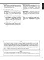
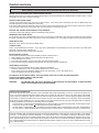
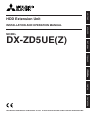
ENGLISH
HDD Extension Unit
DEUTSCH
INSTALLATION AND OPERATION MANUAL
MODEL
NEDERLANDS
ITALIANO
ESPAÑOL
FRANÇAIS
DX-ZD5UE(Z)
THIS INSTRUCTION MANUAL IS IMPORTANT TO YOU. PLEASE READ IT BEFORE USING YOUR HDD EXTENSION UNIT.
1
WARNING
RISK OF ELECTRIC SHOCK
DO NOT OPEN
WARNING: TO REDUCE THE RISK OF ELECTRIC SHOCK,
DO NOT REMOVE COVER (OR BACK)
NO USER-SERVICEABLE PARTS INSIDE
REFER SERVICING TO QUALIFIED SERVICE PERSONNEL.
The lightning flash with arrowhead symbol, within
an equilateral triangle, is intended to alert the user
to the presence of uninsulated “dangerous voltage”
within the product’s enclosure that may be of
sufficient magnitude to constitute a risk of electric
shock.
The exclamation point within an equilateral triangle
is intended to alert the user to the presence of
important operating and maintenance (servicing)
instructions in the literature accompanying the
appliance.
WARNING:
TO PREVENT FIRE OR SHOCK HAZARD, DO NOT EXPOSE THIS APPLIANCE TO RAIN OR
MOISTURE.
CAUTION:
TO PREVENT ELECTRIC SHOCK DO NOT USE THIS (POLARIZED) PLUG WITH AN
EXTENSION CORD, RECEPTACLE OR OTHER OUTLET UNLESS THE BLADES CAN BE
FULLY INSERTED TO PREVENT BLADE EXPOSURE.
••••••••••••••••••••••••••••••••••••••••••••••••••••••••••••••••••••••••••••••••••••••••••••••••••••••••••••••••••••••••••••••••••••••••••••••••••••••••••
i
ENGLISH
AVERTISSEMENT
DANGER D’ÉLECTROCUTION
NE PAS OUVRIR
AVERTISSEMENT: POUR ÉLIMINER TOUT RISQUE D’ÉLECTROCUTION, NE PAS OUVRIR LE COUVERCLE
(OU LA PARTIE ARRIÈRE). AUCUNE PIECE
RÉPARABLE PAR L’UTILISATEUR NE SE
TROUVE À L’INTÉRIEUR.
POUR TOUTE INTERVENTION D’ENTRETIEN
OU DE RÉPARATION SE CONFIER AUX TECHNICIENS QUALIFIÉS.
La flèche symbolisant l’éclair dans un triangle équilateral
a pour objet de tirer l’attention de l’utilisateur sur le fait,
qu’il y a des “tensions dangereuses” non-isolées à
l’intérieur de l’enceinte du produit qui peuvent être
suffisamment importantes pour conduire au risque
d’électrocution.
Le point d’exclamation au sein d’un triangle équilateral a
pour objet de tirer l’attention de l’utilisateur sur le fait qu’il
y a des instructions de mise en service et d’entretien (de
réparation) dans les fiches descriptives de l’appareil qui
doivent obligatoirement être respectées.
AVERTISSEMENT:
AFIN D’ÉVITER TOUT RISQUE D’INCENDIE OU D’ÉLECTROCUTION, NE PAS EXPOSER CET
APPAREIL À LA PLUIE NI À L’HUMIDITÉ.
ATTENTION:
POUR PRÉVENIR LES CHOCS ÉLECTRIQUES NE PAS UTILISER CETTE FICHE POLARISÉE
AVEC UN PROLONGATEUR, UNE PRISE DE COURANT OU UNE AUTRE SORTIE DE
COURANT, SAUF SI LES LAMES PEUVENT ÊTRE INSÉRÉES À FOND SANS EN LAISSER
AUCUNE PARTIE À DÉCOUVERT.
••••••••••••••••••••••••••••••••••••••••••••••••••••••••••••••••••••••••••••••••••••••••••••••••••••••••••••••••••••••••••••••••••••••••••••••••••••••••••
ii
Important safeguards
PLEASE READ ALL THESE INSTRUCTIONS REGARDING YOUR HDD EXTENSION UNIT AND RETAIN FOR FUTURE REFERENCE. FOLLOW ALL WARNINGS AND INSTRUCTIONS MARKED ON THE HDD EXTENSION UNIT.
1. Read Instructions
All the safety and operating instructions should be
read before the appliance is operated.
2. Retain Instructions
The safety and operating instructions should be retained for future reference.
3. Heed Warnings
All warnings on the appliance and in the operating
instructions should be adhered to.
4. Follow Instructions
All operating and use instructions should be followed.
5. Cleaning
Unplug this product from the wall outlet before cleaning. Do not use liquid or aerosol cleaners. Use a
damp cloth for cleaning.
6. Attachments
Do not use attachments not recommended by the
product manufacturer as they may cause
hazards.
7. Water and Moisture
Do not use this product near water – for example,
near a bath tub, wash bowl, kitchen sink, or laundry
tub, in a wet basement, or near a swimming pool,
and the like.
8. Accessories
Do not place the product on an unstable cart, stand,
tripod, bracket, or table. The product may fall, causing serious injury. Any mounting of the appliance
should follow the manufacturer’s instructions, and
should use a mounting accessory recommended by
the manufacturer.
An appliance and cart combination should be moved
with care. Quick stops, excessive force, and uneven
surfaces may cause the appliance and cart combination to overturn.
9. Ventilation
Slots and openings in the cabinet are provided for
ventilation and to ensure reliable operation of the
product and to protect it from overheating, and these
openings must not be blocked or covered. This product should never be placed near or over a radiator or
heat register. This product should not be placed in
a built-in installation such as a bookcase or rack unless proper ventilation is provided or the manufacturer’s instructions have been adhered to.
10.Power Sources
This product should be operated only from the type
of power source indicated on the marking label. For
products intended to operate from battery power,
other sources, refer to the operating instructions.
11. Grounding or Polarization
This product is equipped with a 3-wire groundingtype plug, a plug having a third (grounding) pin. This
plug will only fit into a grounding-type power outlet.
This is a safety feature. If you are unable to insert
the plug into the outlet, contact your electrician to
replace your obsolete outlet. Do not defeat the safety
purpose of the grounding-type plug.
12.Power-Cord Protection
Power-supply cords should be routed so that they
are not likely to be walked on or pinched by items
placed upon or against them, paying particular attention to cord at plugs, convenience receptacles,
and the point where they exit from the appliance.
13.Lightning
For added protection for this product receiver during
a lightning storm, or when it is left unattended and
unused for long periods of time, unplug it from the
wall outlet. This will prevent damage to the product
due to lightning and power-line surges.
14.Overloading
Do not overload wall outlets and extension cords as
this can result in a risk of fire or electric shock.
15.Object and Liquid Entry
Never spill liquid of any kind on the product.
••••••••••••••••••••••••••••••••••••••••••••••••••••••••••••••••••••••••••••••••••••••••••••••••••••••••••••••••••••••••••••••••••••••••••••••••••••••••••
iii
17.Damage requiring Service
Unplug this product from the wall outlet and refer servicing to qualified service personnel under the following conditions:
(a) When the power-supply cord or plug is damaged.
(b) If liquid has been spilled, or objects have fallen
into the product.
(c) If the product has been exposed to rain or water.
(d) If the product does not operate normally by following the operating instructions. Adjust only
those controls that are covered by the operating
instructions as an improper adjustment of other
controls may result in damage and will often require extensive work by a qualified technician to
restore the product to its normal operation.
(e) If the product has been dropped or the cabinet
has been damaged.
(f) When the product exhibits a distinct change in
performance, this indicates a need for service.
18.Replacement Parts
When replacement parts are required, be sure the
service technician has used replacement parts
specified by the manufacturer or have the same
characteristics as the original part. Unauthorized
substitutions may result in fire, electric shock or other
hazards.
ENGLISH
16.Servicing
Do not attempt to service this product yourself as
opening or removing covers may expose you to dangerous voltage or other hazards. Refer all servicing
to qualified service personnel.
19.Safety Check
Upon completion of any service or repairs to this
product, ask the service technician to perform safety
checks to determine that the product is in safe operating conditions.
20.Heat
The product should be situated away from heat
sources such as radiators, heat registers, stoves,
or other products (including amplifiers) that product
heat.
NOTE
This equipment has been tested and found to comply with the limits for a Class A digital device, pursuant
to Part 15 of the FCC Rules. These limits are designed to provide reasonable protection against harmful
interference when the equipment is operated in a commercial environment. This equipment generates,
uses, and can radiate radio frequency energy and, if not installed and used in accordance with the instruction manual, may cause harmful interference to radio communications. Operation of this equipment in a
residential area is likely to cause harmful interference in which case the user will be required to correct the
interference at his own expense. Changes or modifications not expressly approved by the party responsible for compliance could void the user's authority to operate the equipment.
NOTE
THIS CLASS A DIGITAL APPARATUS COMPLIES WITH CANADIAN ICES-003.
CET APPAREIL NUMÉRIQUE DE LA CLASSE A EST CONFORME À LA NORME NMB-003 DU CANADA.
••••••••••••••••••••••••••••••••••••••••••••••••••••••••••••••••••••••••••••••••••••••••••••••••••••••••••••••••••••••••••••••••••••••••••••••••••••••••••
iv
Caution and care
HEAVY OBJECTS SHOULD NEVER BE PLACED ON THE UNIT (E.G., MONITOR)
NEVER TOUCH OR INSERT ANY OBJECT INSIDE THE UNIT
Touching the inside of the cabinet or inserting foreign objects of any kind through the ventilation holes not only creates a safety
hazard but can also cause extensive damage.
PROTECT THE POWER CORD
Damage to the power cord may cause fire or shock hazard. If the mains cord is damaged, turn OFF the MAIN switch and
carefully unplug the cord by holding the mains plug.
If this unit is moved with the power on status, the HDDs may be damaged. Ensure that more than one minute have passed
since the power cord and the connecting cords were disconnected, then move this unit.
UNPLUG THE POWER CORD DURING A LONG ABSENCE
Turn off the power and unplug the power cord during a long absence.
MAINTAIN GOOD VENTILATION
Do not obstruct the many ventilation holes on the unit. For maximum ventilation, leave some space around the unit and place
the unit on a hard level surface only, and ensure it is not covered during use. Heavy objects should never be placed on the unit.
WHEN NOT IN USE
When not in use, always turn OFF the MAIN switch.
CABINET CARE
Never use petroleum-based cleaners. They may cause deterioration or coat flaking of the unit. Clean with a soft cloth moistened with soap and water and wipe dry.
When using chemical duster, follow the instructions.
INSTALLATION LOCATION
For excellent performance and lasting reliability install in a location that is:1. Well ventilated, out of direct sunlight and away from direct heat.
2. A solid vibration-free surface.
3. Free from high humidity, excessive dust and away from magnetic fields.
4. Please ensure that the ventilation fan located on the unit’s back panel is not blocked.
UNSUITABLE LOCATIONS
Placing the unit in the following places might shorten the product life:
• Extremely cold places, such as refrigerated warehouses and ice houses
• Places where excessive hydrogen sulfide is likely to be generated, such as hot-springs areas
• Places or locations with salt air environment.
NO OBJECTS FILLED WITH LIQUIDS, SUCH AS VASES, SHALL BE PLACED ON THE APPARATUS.
DO NOT PLACE HEAVY OBJECT ON THIS UNIT.
DO NOT STEP ONTO THIS UNIT.
WARNING:
TO PREVENT FIRE OR SHOCK HAZARD, DO NOT EXPOSE THIS APPARATUS TO RAIN OR MOISTURE. THIS APPARATUS MUST BE GROUNDED.
MAINS LEAD CONNECTION
The mains lead on this Unit is fitted with a non-rewireable mains plug, incorporating a 5A fuse. If you need to replace the
fuse, use a 5A fuse approved by BSI or ASTA to BS 1362, ensuring you refit the fuse cover. If the mains plug is not suitable
for the sockets in your home, and you require to remove the plug, remove the fuse, cut off the plug then dispose of the plug
immediately, to avoid a possible electric shock hazard. To refit a new plug, follow these instructions; Green-and-yellow:
Earth, Blue: Neutral and Brown: Live. As the colours in the mains lead of this Unit may not correspond with the coloured
markings identifying the terminals in your plug, proceed as follows.
• The wire which is coloured green-and-yellow must be connected to the terminal in the plug which is marked by the letter
E or by the safety earth symbol or coloured green or green-and-yellow.
• The wire which is coloured blue must be connected to the terminal which is marked with the letter N or coloured black.
• The wire which is coloured brown must be connected to the terminal which is marked with the letter L or coloured red.
This unit complies with the requirements of the EC Directive 89/336/EEC, “EMC Directive” and 73/23/EEC, “Low Voltage
Directive”, as amended by Directive 93/68/EEC. The requirements for the susceptibility according to EN 55024 and the
requirements for interference according to EN 55022 (Class B) are observed for the operation on residential areas, business, light industrial premises and in small scale enterprises, inside as well as outside of the building. All places of operation
are characterised by their connection to the public low voltage power supply system. This unit is manufactured in accordance with EN 60950.
••••••••••••••••••••••••••••••••••••••••••••••••••••••••••••••••••••••••••••••••••••••••••••••••••••••••••••••••••••••••••••••••••••••••••••••••••••••••••
2
ENGLISH
WARNING:
The power cords for use in the U.S., the continent of Europe, and U.K. are included with this unit.
Use the appropriate one for your country.
The power cord for use in the U.S. is used for 120V only. Never connect to any outlet or power suply
having a different voltage or frequency.
Before starting recording important images, make sure to perform trial recording to ensure that images are properly recorded. The user will not be indemnified for problems (e.g., recording failure or playback failure) that occur with either the
unit or a connected device during operation. It is recommended that backups of important recordings are made regularly
as a precaution against possible breakdowns and accidents.
•
•
•
•
•
This unit uses a hard disk, which is a precision device. Please handle this unit with sufficient care.
Do not subject this unit to vibrations or shocks. This may cause trouble specially when the power of the unit is turned on
or when the hard disk is being accessed, and sufficient care is required.
Do not disconnect the power plug or the USB cable while the power of the unit is turned on or while recording or playing.
For early detection of faults, we recommend that you request inspection once a year.
Do not move this unit at least one minute after the power is turned off.
The hard disk and cooling fan are not permanent items and will need replacement with time. When operated in an ambient
temperature of 25 °C, it is recommended that both of the hard disk and fan are replaced every 30,000 hours.
(This figure is only a guide, and should not be taken as a guaranteed lifespan of the products. Use the <Elapsed Operating
Time> (System Menu Service Info) of the DX-TL5000U/E as a guide to perform checkups.)
INSTALLATION LOCATION AND HANDLING
• Do not plug this unit into the same outlet which is being used for other large power consuming equipment such as a copying
machine and air conditioner.
• Do not place this unit close to other equipment to prevent adverse interference between them.
• Do not place this unit close to strong magnetized objects. They may cause effects on the images or loss of recorded data.
• Never apply volatile substances such as insecticides and do not put rubber- or plastic-products on the unit for a long period.
They may cause deterioration of this unit or flaking of the coating.
• Keep the allowable ambient temperature. When using this unit at a low temperature, turn on the power and wait for 10
minutes or more before use.
WHEN MOVING THIS UNIT
• When you move this unit, make sure to turn off the power and unplug. When a strong shock is applied to this unit while it is
on, the electronic parts inside the unit may be damaged. Take care especially while the ACCESS indicator is illuminating.
• When you move this unit, wrap it with cushions to avoid shock to the internal parts.
COPYRIGHT
• This unit records images digitally. When recording copyrighted images, be careful not to infringe their copyrights.
Disclaimer
In any event, Mitsubishi assumes no responsibility or reliability for the following:
1. Disassembly, repair, or alteration of this unit by user or installer.
2. Failure or breakdown in or damage to this unit resulting from misuse or careless handling by user or installer.
3. Inconvenience or damages arising out of inability to display or record images due to any reason or cause other than
breakdown or failure in this unit.
4. Failure in this unit due to combination with other equipment manufactured by a third party or inconvenience or damages
resulting from such failure.
5. Inconvenience, damages, or claims arising out of breakdown in this unit or loss of recorded video data due to replacement of the HDD by user or installer.
6. Inconvenience or damages arising out of breakdown in this unit or inability to display or record images due to natural
disaster including earthquake and storm.
7. Inconvenience, damages, or claims arising out of breakdown in this unit or loss of recorded video data due to impact or
vibration to the HDD or an environmental factor such as temperature at the installation site.
8. Demand for damages or other claim of infringement of privacy if the images monitored or recorded by user become
public or are used for any purpose other than surveillance for whatever reason.
••••••••••••••••••••••••••••••••••••••••••••••••••••••••••••••••••••••••••••••••••••••••••••••••••••••••••••••••••••••••••••••••••••••••••••••••••••••••••
3
Contents
Important safeguards .................................................... i-iv
Caution and care ............................................................ 2-3
Contents ............................................................................. 4
Major operations and their functions ........................... 5-6
Front view ................................................................ 5
Rear view ................................................................. 6
Connections ................................................................ 7 -13
1. Connectable recorders ........................................ 7
2. Connection example ............................................ 7
3. Startup ................................................................. 8
4. Setting ............................................................. 8-10
5. Attaching and removing the HDD ................. 10-12
6. Troubleshooting ................................................. 13
7. Maintenance ...................................................... 13
How to read this manual
• Viewing displays
(Refer to this information when operating):
Reference information concerning operation
(Caution required):
Cautionary items concerning operation
Recording time table .................................................. 14-17
Specifications .................................................................. 18
••••••••••••••••••••••••••••••••••••••••••••••••••••••••••••••••••••••••••••••••••••••••••••••••••••••••••••••••••••••••••••••••••••••••••••••••••••••••••
4
Major operations and their functions
2
1
POWER
HDD EXTENSION UNIT DX-ZD5
HDD 1
HDD 2
ENGLISH
Front view
3 4
TEMP
FAN
ACCESS
1. POWER indicator
When the EXTERNAL CONTROL switch is set to OFF,
or it is set to ON with the connected recorder turned
on, this indicator illuminates while the MAIN switch on
the rear panel is turned on.
2. HDD indicators (ACCESS indicators)
Momentary flash during accessing HDD 1 or HDD 2.
Flash during recording/copying data.
3. TEMP indicator
Illuminates when the internal temperature of this unit
becomes high.
4. FAN indicator
Illuminates when the fan stops.
••••••••••••••••••••••••••••••••••••••••••••••••••••••••••••••••••••••••••••••••••••••••••••••••••••••••••••••••••••••••••••••••••••••••••••••••••••••••••
5
Major operations and their functions
Rear view
3
EXTERNAL
CONTROL
ON
OFF
MAIN
OFF
ON
4
5
TEMP ALM
FAN ALM
2
CONT IN
CONT OUT
CONT OUT
1
~
AC IN
100-240V
1. MAIN switch
This is the main power switch. When using this unit,
set this switch to ON.
2. AC power socket
Used to connect the power cord. Earth terminal is used
for safety. Use the 100 to 240 V plug with earth for the
power of this unit.
• When the power outlet does not have an earth
terminal, ask for your dealer of the earth work (pay
service). Never connect the earth terminal on the
power supply to a gas pipe, water pipe, conductor
rod, and so on.
• Please use the supplied AC power cord.
• Make sure to plug this unit into the outlet of the same
system which is being used for the recorder
connected. When this unit is plugged into the outlet
of other system, recording or copying after a power
failure will not be carried out correctly.
6
SERIAL BUS
IN
OUT
4. I/O terminals
CONT IN terminal
Terminal for inputting the power on/off status of the
recorder. Connect this terminal with the DC 12V OUT
terminal of the recorder.
CONT OUT terminal
Terminal for outputting the power on/off status of the
recorder. When using multiple number of HDD extension unit and using the power on/off linkage function,
connect this terminal with the CONT IN terminal of the
unit to be connected.
GND terminals
They are the common GND terminals. When using the
power on/off linkage function, connect this terminal with
the GND terminal of the recorder.
TEMP ALM terminal
Terminal for informing the internal high temperature to
the external device.
3. EXTERNAL CONTROL switch
Set this switch to ON (left side) to turn on and off the
power of this unit to link the recorder’s switch. When
not linking the recorder, set this switch to OFF (right
side).
FAN ALM terminal
Terminal for informing abnormality of the fan.
5. SERIAL BUS input port
Port for connecting with the recorder.
• When the EXTERNAL CONTROL switch is set to ON,
make sure to connect the CONT IN terminal of this
unit and DC 12V OUT terminal of the recorder, and
the GND terminal of this unit and GND terminal of the
recorder respectively. When the recorder is turned
on, this unit is turned on linking with the recorder.
• It is recommended to use this unit linking with the
recorder in order to give the internal hard disks a rest
or a proper countermeasure is taken when a problem
occurs on the recorder.
6. SERIAL BUS output ports
Ports for connecting with another DX-ZD5UE(Z) when
using multiple number of DX-ZD5UE(Z).
• It is impossible to supply 5V DC power from this port.
• Do not connect any devices other than DX-ZD5UE(Z)
to these output ports.
••••••••••••••••••••••••••••••••••••••••••••••••••••••••••••••••••••••••••••••••••••••••••••••••••••••••••••••••••••••••••••••••••••••••••••••••••••••••••
6
Connections
ENGLISH
1. Connectable recorders
MITSUBISHI DIGITAL RECORDER DX-TL5000U, DX-TL5000E
2. Connection example
• Connect this unit and a digital recorder by using the supplied USB cable.
• It is possible to connect some DX-ZD5UE(Z), as shown below.
Digital recorder DX-TL5000U or DX-TL5000E
IN
OUT
1
2
3
4
5
6
7
VIDEO
8
VIDEO
OPTION SLOT
Y/C
OUTPUT A OUTPUT B
CAMERA
CLAMPER
IN
OUT
9
10
11
12
13
14
15
OUT
16
IN
HDD extension unit DX-ZD5UE(Z)
VIDEO CASCADE
SERIAL BUS SERIAL BUS
LAN-A
LAN-B
CLAMPER
OFF
ON
ALARM OUT
ALARM IN
10 100
CLOCK ADJ
CLOCK ADJ OUT
REC
REC STOP
EMERGENCY
RESERVED
MODE OUT 1 +
MODE OUT 1 –
MODE OUT 2 +
MODE OUT 2 –
MODE OUT 3 +
MODE OUT 3 –
MODE OUT 4 +
MODE OUT 4 –
CALL OUT +
CALL OUT –
GND
MAX 350mA
DC 12V OUT
GND
RS-232C
1
2
3
4
5
6
7
8
9
10
11
12
13
14
15
16
~
1
2
3
4
5
6
7
8
9
10
11
12
13
14
15
16
AC IN
MAIN
STORAGE
COM
RS485
OUT
10
RS485
IN
PTZ
RS485 TERM +
RS485 TERM –
GND
RS422 +
RS422 –
GND
RS232
100
RESET
100V
Serial bus port
SERIAL BUS
output port
USB cable
SERIAL BUS input port
SERIAL BUS input port
• The EXTERNAL CONTROL switch is set to ON at shipping. At this status, this unit does not work though you
connet the power cord and set the MAIN switch to ON.
Connect this unit and the recorder as “Connection to link the power supply of the recorder and this unit” shown
below.
• Up to 7 of HDD extension units can be used for one DX-TL5000U (or DX-TL5000E).
• It is not available to connect 5 or more HDD extension units in series.
Connection to link the power supply of the recorder and this unit
• Set the EXTERNAL CONTROL switch to ON and connect the terminals as shown below. It is recommended to use
this unit by linking the recorder’s power supply.
• To resume recording or copying after a power failure during normal recording or timer recording, plug this unit into
the outlet of the same system which is being used for the recorder connected.
HDD extension unit
CONT IN
CONT OUT
CONT OUT
GND
GND
TEMP ALM
FAN ALM
HDD extension unit
CONT IN
CONT OUT
CONT OUT
GND
GND
TEMP ALM
FAN ALM
CLOCK ADJ
CLOCK ADJ OUT
REC
REC STOP
EMERGENCY
RESERVED
MODE OUT 1 +
MODE OUT 1 –
MODE OUT 2 +
MODE OUT 2 –
MODE OUT 3 +
MODE OUT 3 –
MODE OUT 4 +
MODE OUT 4 –
CALL OUT +
CALL OUT –
GND
MAX 350mA
DC 12V OUT
Digital recorder
••••••••••••••••••••••••••••••••••••••••••••••••••••••••••••••••••••••••••••••••••••••••••••••••••••••••••••••••••••••••••••••••••••••••••••••••••••••••••
7
Connections
3. Startup
step1.
Turn on the power of this unit.
step2.
Turn on the main switch of the recorder.
The POWER indicator of this unit illuminates.
step3.
After “POWER OFF” is displayed on the LCD of the recorder, press the POWER button of the recorder.
step4.
The indicators of HDD 1 and HDD 2 momentary flash in green.
When the power of the recorder is turned on, the connection is completed.
4. Setting
This unit can be used as a main device or copy device. Before using, set the details with the menu of the recorder.
Setting of the recorder
Setting of this unit for the main device or copy
device
System Menu
5 Memory
Notes for using this unit
This unit can be used as an additional memory or a copy
device. However, when you carry out recording or playback in a high quality mode or at a high rate, pictures may
be lost during recording or playback. Carry out trial operation before the actual operation.
Connecting this unit and setting the ID number
1 Add/Remove HDD Device
steps
1, 2
2 External HDD (USB HDD)
For connecting this unit to the recorder, use the USB 2.0
cable. The ID number is not necessary to be set because
the unit automatically recognizes the HDD attached.
Make sure that the MAIN switch on the rear panel is turned
off before connecting this unit.
step1.
step2.
Make sure that the USB HDDs connected to the
recorder are displayed in the screen of <External
HDD (USB HDD)>.
The order of recording/playback when the recorder’s
HDDs and this unit are registered as the main device
The order of the recorder’s internal HDD used for recording/playback is: internal A internal B internal C.
• When the “SB:” button of the desired ID number
is pressed, the access LED on the device
illuminates and you can check the corresponding
HDD which is connected to the SERIAL BUS
port.
When all the built-in HDDs of the recorder are used up,
recording/playback starts with the HDDs registered as Main
in ascending sequence of their ID numbers.
Add the USB HDD for setting the main or copy
device.
Serial bus ID01 Serial bus ID02
ID16 (at the maximum)
Main: Registers for the main device. The numbers
indicate the recording order.
Copy1: Registers for the copy 1 device. The
numbers indicate the recording order.
Copy2: Registers for the copy 2 device. The
numbers indicate the recording order.
Free: Does not register as the main or copy device.
• The button changes in the order of “Main,”
“Copy1,” “Copy2,” and “Free” each time you
press the button.
• The copied data is transmitted in 2 MB units. The
copy of up to 2 MB of the latest data may be delayed.
Be careful when changing the copy device.
• The maximum number of devices connected via the
serial bus is 16, including the built-in DVD of the
recorder and memory devices. This number is the
total of devices registered as Main, Copy 1, and Copy
2.
••••
Serial bus
In case of serial bus HDD, the HDD which is added latest
is registered last. However, the serial bus HDD newly connected can be registered to the middle number. When the
HDD being used is removed, the HDD added is registered
to the ID of the removed number.
When copying data with this unit
Copy 1
Data can be copied by specifying the start and end points
of copying. The points are specified by the date and time
or the book mark. This function is useful for copying the
data of the short period of time.
• Before executing the copy, make sure that the
recorder and this unit are connected and the <Add/
Remove HDD Device> (System Menu Memory) is
set in the recorder correctly.
• The order of the main device used for recording is:
internal HDD USB HDD.
••••••••••••••••••••••••••••••••••••••••••••••••••••••••••••••••••••••••••••••••••••••••••••••••••••••••••••••••••••••••••••••••••••••••••••••••••••••••••
8
User Menu
2 Copy
step
4
step
3
steps
1, 2
1 Copy Data to Copy 1 Drive
1 + 2 Range of Copy
3 Set Copy 1 Drive
step1.
Set the camera number to be copied.
• The button function changes between “All Off”
and “All On” each time you select this button. You
can switch on and off for all the cameras easily
by using this button.
• The picture is not copied when there is no
recorded picture of the set camera number or
time.
step2.
This item is used to copy the data by specifying only the
start point. The point is specified by the date and time or
the bookmark. The copy continues until the end point of
the recording data reaches or the media to be copied becomes full unless the copy is stopped manually (when “FIFO
Overwrite” is set to “Off”). This function is useful for making
backup of the recording data.
• Before executing the copy, make sure that the
recorder and this unit are connected and the <Add/
Remove HDD Device> (System Menu Memory) is
set in the recorder correctly.
User Menu
2 Copy
step3.
Set the start, start/end, or end points of copy by
specifying the date and time or the book mark
number.
Start: Sets only the start point of copy.
Start/End: Sets the start and end points of copy.
End: Sets only the end point of copy.
• To set the book mark point, select “Bookmark”
and then select the desired book mark number.
• To copy from the oldest recording time, select
“Copy Start Time.” To copy to the latest recording
time, select “Copy End Time.”
step4.
Select “Execute.”
• The copy starts.
• To stop the copy manually, select “Cancel” in the
progress screen. The data which has been copied
before cancelling is copied.
4
step
3
steps
1, 2
1 + 2 Range of Copy
4 Set Copy 2 Drive
step1.
Set the camera number to be copied.
• The button function changes between “All Off”
and “All On” each time you select this button. You
can switch on and off for all the cameras easily
by using this button.
• The picture is not copied when there is no
recorded picture of the set camera number or
time.
step2.
• “Alarm” appears for “From Main” when “Alarm
Recording Area” (System Menu Memory Data
Management Setting for Main Memory Change
Partition Setting) is set to other than “0 %” in the
recorder.
• “LPA” appears for “From Main” when “Long Pre-Alarm
Area” (System Menu Memory Data Management
Setting for Main Memory Change Partition Setting)
is set to other than “0 %” in the recorder.
step
2 Copy Data to Copy 2 Drive
Select “Other settings” and then set the detailed
settings.
From Main: Sets the area which contains the data
to be copied. The available setting items are
“Normal,” “Alarm,” and “LPA.”
To Copy 1: Sets the group name to where the data
is copied. The available setting items are
“SerialBus,” “NAS,” “SCSI,” “DVD/CD,” and
“USBMemory.” Set this unit to “SerialBus.”
Copy Data: Sets the data area to be copied. The
available setting items are “Alarm” and “All.”
Overwrite: Selects whether or not to overwrite the
existed data.
Auto Eject: Selects whether to eject media
automatically when the copy is over. This menu is
not available for this unit.
ENGLISH
Copy 2
Select “Other settings” and then set the detailed
settings.
From Main: Sets the area which contains the data
to be copied. The available setting items are
“Normal,” “Alarm,” and “LPA.”
To Copy 2: Sets the group name to where the data
is copied. The available setting items are
“SerialBus,” “NAS,” “SCSI,” and “DVD/CD.” Set this
unit to “SerialBus.”
Copy Data: Sets the data area to be copied. The
available setting items are “Alarm” and “All.”
Overwrite: Selects whether or not to overwrite the
existed data.
Auto Eject: Selects whether to eject media
automatically when the copy is over. This menu is
not available for this unit.
FIFO Overwrite: Selects whether to repeat copying
from the start point of the media by overwriting the
existed data, or to stop copying when the capacity
of the media becomes full during copying.
• “Alarm” appears for “From Main” when “Alarm
Recording Area” (System Menu Memory
Data
Management Setting for Main Memory
Change
Partition Setting) is set to other than “0 %”
in the recorder.
••••••••••••••••••••••••••••••••••••••••••••••••••••••••••••••••••••••••••••••••••••••••••••••••••••••••••••••••••••••••••••••••••••••••••••••••••••••••••
9
Connections
• “LPA” appears for “From Main” when “Long Pre-Alarm
Area” (System Menu Memory Data Management
Setting for Main Memory Change Partition Setting)
is set to other than “0 %” in the recorder.
• Make sure that the MAIN switch on the rear panel is
turned OFF when attaching or removing the HDD.
Wait at least 1 minute after turning off the power. When
a recorder is connected, turn off the recorder, too.
step3.
• Do not remove the top cover of the unit.
• When a power failure occurs during recording, avoid
adding, replacing or transporting the HDD. In this
case, as the recorded data may be erased, turn the
power back on to boot up the unit normally with the
HDD that was being used at the time of the power
failure attached. Then add, replace, or transport the
HDD.
Set the start time of copy.
Start: Sets the start point of copy.
Continue: Starts copying from the end point of the
previous copy.
• To set the start point using the book mark, select
“Bookmark” and then select the desired book
mark number.
• To copy from the oldest recording time, select
“Copy Start Time.”
step4.
Select “Execute.”
• The copy starts.
• To stop the copy manually, select “Cancel” in the
screen of <Copy Data to Copy 2 Drive>. The data
which has been copied before cancelling is
copied.
• The warning is displayed when the copied range
exceeds the available capacity of the device to be
copied when “FIFO Overwrite” is set to “Off” and copy
destination is HDD. In this case, set the copy setting
again with narrower copy range or use a copy device
with larger capacity.
• When the copy is performed during recording, the
picture of the recording start and end points may not
be recorded.
• The progress bar of copy is not displayed for copy 2.
• The picture data is processed in 2 MB unit. Therefore
the data is copied in 2 MB unit from the start point of
the designated range when copying.
5. Attaching and removing the HDD
Up to 2 HDDs can be mounted on this unit. The attaching,
removing and replacing method of the HDDs are as follows.
• HDD is very delicate. Handle the HDD with care and
follow the precautions below because even a small
shock may damage the internal components of the
HDD.
• Do not drop the HDD. Also do not put the metallic
object such as a coin or a screw driver into the HDD
tray.
• Do not place the HDD on a desk or a table directly.
Put a thick cushion under the HDD because even a
small shock may damage the internal components
of the HDD.
• Do not use an electric screwdriver. Vibrations and
shocks caused by an electric screwdriver may
damage the internal components of the HDD.
• When replacing the HDD, do not knock the HDD
with other components such as the another HDD
and the HDD tray.
• Do not knock the HDD with tools such as a driver
when replacing the HDD.
• The following HDD has been tested and compatibility
is ensured. This information is as of December 2004.
Supply of this HDD may be stopped or it may be
changed without notice by its manufacturer. Consult
your dealer for the latest information or use of other
HDDs. When you attach multiple HDDs, normally use
the HDDs of the same capacity and the same model
name.
<Hitachi Global Storage Technologies>
HDS724040KLSA80 (400 GB, S-ATA)
When attaching a HDD
• Disconnect the power supply from the Mains before
installing or removing the HDD.
step1.
Push the left end of each screw covers on both sides
of the cover to open.
• When attaching the HDDs, attach in the order of HDD
1, and 2.
Precautions for installation
• Do not leave the screw cover open for general use.
Precautions for attaching or removing the HDD
• Do not attach or remove the HDD unnecessarily.
Attaching or removing the HDD of DX-ZD5UE(Z) is
intended to replace the faulty HDD or add the HDD
when starting operation for the first time because of
the structure of the connectors. It is not presumed to
be used as a removable HDD.
••••••••••••••••••••••••••••••••••••••••••••••••••••••••••••••••••••••••••••••••••••••••••••••••••••••••••••••••••••••••••••••••••••••••••••••••••••••••••
10
Remove the screws.
step7.
Attach the new HDD onto the HDD tray with four
screws.
ENGLISH
step2.
• Make sure to attach the HDD in the correct
direction.
• When attaching the HDD to this unit, use the supplied
screws.
step3.
Remove the front covers.
• Remove the cover on the right side first.
• Then, push the left side cover to the right to
remove.
step4.
step5.
step8.
Insert the hard disk tray halfway.
step9.
Connect the cords.
step10.
Insert the hard disk tray completely.
Disconnect the cord connected to the circuit board
on the metal part.
Remove the metal part.
• Remove 4 screws on the metal part.
step6.
Pull out the HDD tray completely.
HDD 1
HDD 2
••••••••••••••••••••••••••••••••••••••••••••••••••••••••••••••••••••••••••••••••••••••••••••••••••••••••••••••••••••••••••••••••••••••••••••••••••••••••••
11
Connections
step11.
Attach the metal part.
step15.
Fix the front covers with two screws.
step16.
Close the left end of each screw covers on both sides
of the cover.
• Adjust the upper side first, then push the lower
side into the unit.
• Take care not to deform the springs.
step12.
Fix the metal part with four screws.
step13.
Connect the cord to the circuit board on the metal
part.
step14.
Attach the front covers.
• Follow the same procedures when attaching a HDD
to HDD 2, or removing or replacing the HDDs.
• Attach the left side cover and push to the left.
• Then, attach the right side cover.
••••••••••••••••••••••••••••••••••••••••••••••••••••••••••••••••••••••••••••••••••••••••••••••••••••••••••••••••••••••••••••••••••••••••••••••••••••••••••
12
ENGLISH
6. Troubleshooting
If problems with the unit persist even after you’ve followed the suggestions below, please disconnect the power cord and
contact the retailer from whom you purchased the unit.
Description of problem
The unit is not turned on.
This unit does not work
correctly.
TEMP indicator illuminates.
FAN indicator illuminates.
Please consult the following
• Is the power cord properly plugged in?
• Is the EXTERNAL CONTROL switch set to ON though the DC 12 V OUT
terminal of the recorder and the CONT IN terminal of this unit are not
connected ?
• Is the USB cable connected correctly?
• Are the menus set correctly in the recorder?
• Are the recording devices connected exceeding the specified connectable
number?
• Turn off the power. Turn on the power again after the internal temperature
drops.
• Replace the fan with new one. Ask your dealer to replace the fan.
7. Maintenance
The elapsed operating time, which can be a guide to know the periodic maintenance timing, is available in the <Elapsed
Operating Time> menu (System Menu Service Info Elapsed Operating Time) of the recorder. Refer to the installer’s
manual of the recorder. The indication of the operating time of the recorder may vary from the actual operating time. It is
recommended to use this indication just for your reference.
When this unit is registered as a Copy 1 device, check the indication of Copy 1, SerialBus.
When this unit is registered as a Copy 2 device, check the indication of Copy 2, SerialBus.
When this unit is registered as a Main device, the elapsed operating time of this unit is not displayed. (The elapsed
operating time of the recorder connected with this unit is displayed.)
••••••••••••••••••••••••••••••••••••••••••••••••••••••••••••••••••••••••••••••••••••••••••••••••••••••••••••••••••••••••••••••••••••••••••••••••••••••••••
13
Recording time table
Continuous recording time table
HDD continuous recording time
Displays the estimated recordable time (when recording on two 250 GB HDDs).
• The following table shows the total number of recordable frames of all the cameras which are set for recording.
• When recording data in NTSC system
• Without audio recording
d : day, h : hour
Number of frames
/sec.
Picture grade
240
Super
Fine
120
80
60
48
32
30
15h
1d7h
1d23h
18h
1d12h
2d7h
2d15h
3d7h
4d22h
3d1h
3d20h
5d18h
High
22h
1d20h
2d18h
3d16h
4d15h
Standard
1d3h
2d7h
3d11h
4d15h
Basic
1d13h
3d2h
4d15h
Long
2d7h
4d15h
10
Super
Fine
Number of frames
/sec.
Picture grade
16
13
5d6h
9d21h
12d4h
6d3h
11d13h
14d5h
6d22h
7d9h
13d21h
17d2h
5d19h
8d16h
9d6h
17d9h
21d9h
6d4h
7d17h
11d14h
12d9h
23d4h
28d13h
6d23h
9d7h
11d14h
17d10h
18d14h
34d20h
42d21h
8
4
2
1
0.5
0.25
0.125
15d19h
19d18h
39d13h
79d3h
158d7h
316d15h
633d7h
1266d15h 13,678,000
Number of
recording field
18d11h
23d2h
46d5h
92d11h
184d22h
369d21h 739d19h
1479d14h 15,978,000
High
22d5h
27d18h
55d13h
111d2h
222d5h
444d10h 888d20h
1777d16h 19,198,000
Standard
27d19h
34d18h
69d12h
139d1h
278d2h
556d5h 1112d10h 2224d20h 24,026,000
Basic
37d3h
46d9h
92d19h
185d15h
371d6h
742d12h 1485d1h
2970d3h
Long
55d18h
69d16h
139d9h
278d19h
557d14h
1115d4h 2230d8h
4460d17h 48,174,000
32,077,000
••••••••••••••••••••••••••••••••••••••••••••••••••••••••••••••••••••••••••••••••••••••••••••••••••••••••••••••••••••••••••••••••••••••••••••••••••••••••••
14
ENGLISH
• With audio recording <Audio recording using 12.8 KHz PCM sampling is possible.>
d : day, h : hour
Number of frames
/sec.
240
120
80
60
48
32
30
16
13
Audio Channel 1
Audio Channel 2
Audio Channel 3
Audio Channel 4
Audio Channel 1
Audio Channel 2
Audio Channel 3
Audio Channel 4
Audio Channel 1
Audio Channel 2
Audio Channel 3
Audio Channel 4
Audio Channel 1
Audio Channel 2
Audio Channel 3
Audio Channel 4
Audio Channel 1
Audio Channel 2
Audio Channel 3
Audio Channel 4
Audio Channel 1
Audio Channel 2
Audio Channel 3
Audio Channel 4
15h
15h
15h
15h
18h
18h
18h
18h
22h
22h
22h
22h
1d3h
1d3h
1d3h
1d3h
1d12h
1d12h
1d12h
1d12h
2d7h
2d7h
2d6h
2d6h
1d7h
1d7h
1d7h
1d7h
1d12h
1d12h
1d12h
1d12h
1d20h
1d20h
1d19h
1d19h
2d7h
2d7h
2d6h
2d6h
3d1h
3d1h
3d
3d
4d14h
4d13h
4d12h
4d11h
1d23h
1d23h
1d22h
1d22h
2d7h
2d6h
2d6h
2d6h
2d18h
2d17h
2d17h
2d17h
3d10h
3d10h
3d9h
3d8h
4d14h
4d13h
4d12h
4d10h
6d20h
6d18h
6d15h
6d13h
2d14h
2d14h
2d14h
2d13h
3d1h
3d
3d
2d23h
3d16h
3d15h
3d14h
3d14h
4d14h
4d12h
4d11h
4d10h
6d2h
6d
5d22h
5d20h
9d2h
8d22h
8d17h
8d13h
3d6h
3d6h
3d5h
3d4h
3d19h
3d18h
3d18h
3d17h
4d13h
4d12h
4d11h
4d10h
5d17h
5d15h
5d13h
5d12h
7d14h
7d11h
7d8h
7d5h
11d7h
11d
10d18h
10d12h
4d21h
4d20h
4d18h
4d17h
5d16h
5d15h
5d13h
5d11h
6d20h
6d17h
6d15h
6d12h
8d12h
8d8h
8d5h
8d1h
11d7h
11d
10d18h
10d12h
16d18h
16d3h
15d14h
15d1h
5d5h
5d3h
5d2h
5d
6d1h
5d23h
5d22h
5d20h
7d6h
7d4h
7d1h
6d22h
9d1h
8d21h
8d17h
8d13h
12d
11d17h
11d10h
11d3h
17d20h
17d3h
16d12h
15d22h
9d16h
9d11h
9d6h
9d2h
11d6h
10d23h
10d17h
10d11h
13d11h
13d1h
12d16h
12d8h
16d17h
16d2h
15d13h
15d
22d1h
21d
20d1h
19d4h
32d7h
30d3h
28d5h
26d13h
11d20h
11d13h
11d6h
10d23h
13d18h
13d8h
12d23h
12d14h
16d11h
15d20h
15d7h
14d19h
20d9h
19d12h
18d16h
17d22h
26d20h
25d7h
23d22h
22d17h
39d3h
35d23h
33d6h
30d23h
10
8
4
2
1
0.5
0.25
0.125
Audio Channel 1
Audio Channel 2
Audio Channel 3
Audio Channel 4
Audio Channel 1
Audio Channel 2
Audio Channel 3
Audio Channel 4
Audio Channel 1
Audio Channel 2
Audio Channel 3
Audio Channel 4
Audio Channel 1
Audio Channel 2
Audio Channel 3
Audio Channel 4
Audio Channel 1
Audio Channel 2
Audio Channel 3
Audio Channel 4
Audio Channel 1
Audio Channel 2
Audio Channel 3
Audio Channel 4
15d6h
14d18h
14d7h
13d20h
17d18h
17d1h
16d10h
15d20h
21d3h
20d4h
19d7h
18d12h
26d4h
24d17h
23d10h
22d5h
34d6h
31d19h
29d16h
27d20h
49d13h
44d14h
40d13h
37d4h
18d22h
18d4h
17d10h
16d19h
21d23h
20d22h
19d23h
19d3h
26d3h
24d16h
23d9h
22d5h
32d5h
30d1h
28d3h
26d11h
42d
38d9h
35d8h
32d18h
60d6h
53d2h
47d10h
42d21h
36d8h
33d14h
31d5h
29d3h
41d21h
38d6h
35d5h
32d15h
49d9h
44d10h
40d9h
37d
60d3h
52d23h
47d8h
42d18h
76d19h
65d12h
57d2h
50d15h
106d4h
85d18h
71d22h
61d22h
67d4h
58d7h
51d13h
46d4h
76d12h
65d6h
56d21h
50d10h
88d21h
74d1h
63d11h
55d13h
105d22h
85d13h
71d18h
61d19h
131d
101d6h
82d12h
69d14h
171d13h
123d21h
96d23h
79d15h
116d15h
92d8h
76d10h
65d4h
130d13h
100d21h
82d4h
69d8h
148d3h
111d2h
88d21h
74d1h
171d3h
123d14h
96d17h
79d11h
202d12h
139d5h
106d1h
85d16h
247d19h
159d7h
117d9h
92d22h
184d17h
130d9h
100d18h
82d2h
201d18h
138d17h
105d16h
85d8h
222d5h
148d3h
111d2h
88d21h
247d4h
158d22h
117d2h
92d16h
278d10h
171d8h
123d18h
96d20h
318d14h
185d20h
131d4h
101d9h
260d18h
164d4h
119d19h
94d7h
277d10h
170d17h
123d7h
96d11h
296d6h
177d18h
126d23h
98d18h
317d20h
185d9h
130d20h
101d3h
342d17h
193d16h
135d
103d14h
371d17h
202d18h
139d9h
106d4h
328d9h
188d15h
132d8h
101d21h
341d10h
192d23h
134d12h
103d5h
355d12h
197d12h
136d17h
104d13h
370d19h
202d6h
139d1h
105d22h
387d9h
207d5h
141d10h
107d8h
405d12h
212d9h
143d21h
108d19h
Picture grade
Super
Fine
High
Standard
Basic
Long
Number of frames
/sec.
Picture grade
Super
Fine
High
Standard
Basic
Long
• Continuous recordable time and the estimated time displayed on the menu screen are the continuous recordable
time when operating this unit and is not the product warranty period. Furthermore, it is not the period that guarantees
the operation of used parts.
••••••••••••••••••••••••••••••••••••••••••••••••••••••••••••••••••••••••••••••••••••••••••••••••••••••••••••••••••••••••••••••••••••••••••••••••••••••••••
15
Recording time table
• When recording data in PAL system
• Without audio recording
d : day, h : hour
Picture
Number of frames
/sec.
grade
200
100
66.7
50
40
33.3
25
16
13
Super
16h
1d9h
2d1h
2d18h
3d11h
4d1h
5d12h
8d15h
10d15h
Fine
19h
1d15h
2d10h
3d6h
4d1h
4d19h
6d12h
10d4h
12d12h
High
23h
1d23h
2d23h
3d23h
4d22h
5d19h
7d22h
12d9h
15d6h
Standard
1d6h
2d12h
3d18h
5d1h
6d7h
7d10h
10d2h
15d19h
19d10h
Basic
1d17h
3d11h
5d5h
6d23h
8d16h
10d5h
13d22h
21d17h
26d18h
Long
2d18h
5d13h
8d8h
11d3h
13d22h
16d9h
22d7h
34d20h
42d21h
10
8
4
2
1
0.5
0.25
0.125
13d20h
17d7h
34d14h
69d4h
138d8h
Number of frames
/sec.
Picture grade
Super
276d17h 553d11h
Number of
recording field
1106d22h 11,953,000
Fine
16d7h
20d9h
40d18h
81d12h
163d
326d1h
652d2h
1304d5h
14,084,000
High
19d19h
24d18h
49d13h
99d3h
198d6h
396d12h
793d
1586d1h
17,128,000
Standard
25d6h
31d14h
63d4h
126d8h
252d16h
505d9h 1010d19h 2021d14h 21,832,000
Basic
34d19h
43d11h
86d23h
173d23h
347d23h
695d23h 1391d22h 2783d20h 30,064,000
Long
55d18h
69d16h
139d9h
278d19h
557d14h
1115d4h 2230d8h
4460d17h 48,174,000
••••••••••••••••••••••••••••••••••••••••••••••••••••••••••••••••••••••••••••••••••••••••••••••••••••••••••••••••••••••••••••••••••••••••••••••••••••••••••
16
ENGLISH
• With audio recording <Audio recording using 12.8 KHz PCM sampling is possible.>
d : day, h : hour
Number of frames
/sec.
200
100
66.7
50
40
33.3
25
16
13
Audio Channel 1
Audio Channel 2
Audio Channel 3
Audio Channel 4
Audio Channel 1
Audio Channel 2
Audio Channel 3
Audio Channel 4
Audio Channel 1
Audio Channel 2
Audio Channel 3
Audio Channel 4
Audio Channel 1
Audio Channel 2
Audio Channel 3
Audio Channel 4
Audio Channel 1
Audio Channel 2
Audio Channel 3
Audio Channel 4
Audio Channel 1
Audio Channel 2
Audio Channel 3
Audio Channel 4
16h
16h
16h
16h
19h
19h
19h
19h
23h
23h
23h
23h
1d6h
1d6h
1d6h
1d5h
1d17h
1d17h
1d17h
1d17h
2d18h
2d18h
2d17h
2d17h
1d9h
1d9h
1d8h
1d8h
1d14h
1d14h
1d14h
1d14h
1d23h
1d23h
1d22h
1d22h
2d12h
2d11h
2d11h
2d11h
3d10h
3d10h
3d9h
3d8h
5d12h
5d10h
5d8h
5d7h
2d1h
2d1h
2d1h
2d
2d10h
2d9h
2d9h
2d9h
2d22h
2d22h
2d21h
2d21h
3d18h
3d17h
3d16h
3d15h
5d3h
5d2h
5d
4d23h
8d4h
8d1h
7d21h
7d18h
2d18h
2d17h
2d17h
2d16h
3d5h
3d5h
3d4h
3d4h
3d22h
3d21h
3d20h
3d19h
4d23h
4d22h
4d21h
4d20h
6d20h
6d17h
6d15h
6d13h
10d21h
10d14h
10d8h
10d3h
3d10h
3d9h
3d9h
3d8h
4d
4d
3d23h
3d22h
4d21h
4d20h
4d19h
4d17h
6d5h
6d3h
6d1h
5d23h
8d12h
8d8h
8d5h
8d1h
13d12h
13d2h
12d17h
12d9h
4d
3d23h
3d23h
3d22h
4d17h
4d16h
4d15h
4d14h
5d18h
5d16h
5d14h
5d12h
7d7h
7d4h
7d1h
6d23h
10d
9d18h
9d13h
9d8h
15d19h
15d6h
14d18h
14d7h
5d11h
5d9h
5d8h
5d6h
6d10h
6d8h
6d5h
6d3h
7d18h
7d15h
7d12h
7d9h
9d21h
9d16h
9d11h
9d6h
13d11h
13d2h
12d17h
12d8h
21d5h
20d6h
19d9h
18d14h
8d11h
8d7h
8d4h
8d
9d23h
9d17h
9d12h
9d7h
12d1h
11d17h
11d10h
11d3h
15d6h
14d17h
14d6h
13d19h
20d17h
19d19h
18d23h
18d4h
32d7h
30d3h
28d5h
26d13h
10d9h
10d3h
9d22h
9d17h
12d4h
11d20h
11d13h
11d6h
14d17h
14d6h
13d19h
13d9h
18d14h
17d21h
17d4h
16d13h
25d6h
23d21h
22d16h
21d13h
39d3h
35d23h
33d6h
30d23h
10
8
4
2
1
0.5
0.25
0.125
Audio Channel 1
Audio Channel 2
Audio Channel 3
Audio Channel 4
Audio Channel 1
Audio Channel 2
Audio Channel 3
Audio Channel 4
Audio Channel 1
Audio Channel 2
Audio Channel 3
Audio Channel 4
Audio Channel 1
Audio Channel 2
Audio Channel 3
Audio Channel 4
Audio Channel 1
Audio Channel 2
Audio Channel 3
Audio Channel 4
Audio Channel 1
Audio Channel 2
Audio Channel 3
Audio Channel 4
13d10h
13d
12d15h
12d7h
15d17h
15d4h
14d16h
14d5h
18d23h
18d4h
17d11h
16d19h
23d21h
22d16h
21d14h
20d14h
32d6h
30d2h
28d4h
26d12h
49d13h
44d14h
40d13h
37d4h
16d15h
16d1h
15d11h
14d23h
19d11h
18d15h
17d21h
17d5h
23d11h
22d7h
21d5h
20d6h
29d11h
27d15h
26d
24d14h
39d15h
36d9h
33d15h
31d6h
60d6h
53d2h
47d10h
42d21h
32d2h
29d22h
28d
26d8h
37d7h
34d10h
31d22h
29d19h
44d14h
40d12h
37d3h
34d6h
55d7h
49d4h
44d7h
40d6h
72d18h
62d13h
54d20h
48d20h
106d4h
85d18h
71d22h
61d22h
59d20h
52d17h
47d2h
42d13h
68d20h
59d14h
52d12h
46d23h
81d
68d12h
59d8h
52d8h
98d9h
80d13h
68d5h
59d3h
125d2h
97d16h
80d2h
67d21h
171d13h
123d21h
96d23h
79d15h
105d10h
85d3h
71d9h
61d11h
119d4h
93d22h
77d12h
65d23h
137d1h
104d17h
84d18h
71d4h
161d3h
118d6h
93d10h
77d5h
195d8h
135d19h
104d1h
84d8h
247d19h
159d7h
117d9h
92d22h
170d7h
122d23h
96d6h
79d1h
187d21h
131d23h
101d16h
82d17h
209d11h
142d8h
107d18h
86d17h
236d13h
154d10h
114d15h
91d3h
271d14h
168d17h
122d8h
95d23h
318d14h
185d20h
131d4h
101d9h
245d23h
158d3h
116d12h
92d5h
263d22h
165d11h
120d11h
94d18h
284d16h
173d11h
124d17h
97d9h
308d20h
182d6h
129d6h
100d4h
337d10h
191d23h
134d3h
103d2h
371d17h
202d18h
139d9h
106d4dh
316d6h
184d11h
130d5h
100d15h
330d22h
189d12h
132d18h
102d4h
346d22h
194d18h
135d9h
103d18h
364d13h
200d8h
138d2h
105d9h
383d23h
206d5h
140d22h
107d1h
405d12h
212d9h
143d21h
108d19h
Picture grade
Super
Fine
High
Standard
Basic
Long
Number of frames
/sec.
Picture grade
Super
Fine
High
Standard
Basic
Long
• Continuous recordable time and the estimated time displayed on the menu screen are the continuous recordable
time when operating this unit and is not the product warranty period. Furthermore, it is not the period that guarantees
the operation of used parts.
••••••••••••••••••••••••••••••••••••••••••••••••••••••••••••••••••••••••••••••••••••••••••••••••••••••••••••••••••••••••••••••••••••••••••••••••••••••••••
17
Specifications
General
Rated Power Supply:
Rated Input:
Operating Temperature:
Relative Humidity:
Altitude:
Dimensions:
Weight:
100 to 240 V AC ±10 %, 50/60 Hz
0.7 - 0.4 A (100-240 V)
41 °F-104 °F (5 °C to 40 °C)
Max. 80 (%)
Max. 2000 (m)
424 (Width) x 361 (Depth) x 49 (Height) (mm)
5 kg
Control terminals
CONT IN
CONT OUT
GND (Ground)
TEMP ALM
FAN ALM
EXTERNAL CONTROL:
When set to ON:
Input terminal working with the power supply of the recorder
Output terminal working with the power supply of the recorder
For grounding
Output terminal for detecting abnormality of temperature (open collector output)
Active:
“Low” Level
Max. Drive current 7 mA DC.
Non active:
Open.
Max. Voltage 24 V DC.
Output terminal for detecting abnormality of the fan (open collector output)
Active:
“Low” Level
Max. Drive current 7 mA DC.
Non active:
Open.
Max. Voltage 24 V DC.
When set to OFF:
Power is supplied to the HDD when 12V of voltage is applied to the input terminal working with
the power supply
Power is always supplied to the HDD.
Serial bus terminal
Serial bus terminal (2 terminals)
(Only DX-ZD5UE(Z) is connectable.)
Accessories:
USB2.0 cable
Screws
User’s manual (this manual)
Power cord
1
8
1
3
Control input/output terminals and circuits
TEMP ALM terminal
FAN ALM terminal
• Output Circuit
Output terminal
GND terminal
<Interface circuit inside the unit>
Design and specifications are subject to change without notice.
••••••••••••••••••••••••••••••••••••••••••••••••••••••••••••••••••••••••••••••••••••••••••••••••••••••••••••••••••••••••••••••••••••••••••••••••••••••••••
18
MITSUBISHI DIGITAL ELECTRONICS AMERICA, INC.
9351 Jeronimo Road, Irvine, CA 92618, U.S.A.
Phone 949-465-6000
www.mitsubishi-imaging.com
Tech Support 888-307-0309
[email protected]
UK
Mitsubishi Electric Europe B.V.
UK Branch Office
Visual Information Systems Division
Travellers Lane Hatfield Herts AL10 8XB
Telephone: +44 (1707)-278 684
Fax: +44 (1707)-278 541
GERMANY
Mitsubishi Electric Europe B.V.
German Branch Office
Electric Visual Systems
Gothaer Str. 8 40880 Ratingen Germany
Telephone: +49 (2102)-486 9250
Fax: +49 (2102)-486 7320
SPAIN
Mitsubishi Electric Europe B.V.
Spanish Branch Office
Ctra. de Rubi, 76-80 Apdo.420
08190 Sant Cugat del Valles
(Barcelona) SPAIN
Telephone: +34 (93)-565 3154
Fax: +34 (93)-589 4388
FRANCE
Mitsubishi Electric Europe B.V.
French Branch Office 25,
Boulevard des Bouvets 92741 Nanterre
Cedex
Telephone: +33 (1)-5568 5500
Fax: +33 (1)-5568 5731
872C356A4
ITALY
Mitsubishi Electric Europe B.V.
Italian Branch Office
Centro Direzionale Colleoni
Palazzo Perseo - Ingresso 2, Via
Paracelso 12, 20041 Agrate Brianza, Italy
Telephone: +39 (039)-605 31
Fax: + 39 (039)-605 3214
The Netherlands
Mitsubishi Electric Benelux
A Division of Mitsubishi Electric Europe B.V.
Niiverheidsweg 23A, 3641 RP Mijdrecht
Netherlands.
Telephone: +31 (297)-282 461
Fax: +31 (297)-283 936
Sweden
Mitsubishi Electric Scandinavia
Hammarbacken 14 Box750 SE-191 27
Sollentuna Sweden
Telephone: +46 (8)-625 1000
Fax: +46 (8)-35 1132
Ireland
Mitsubishi Electric Ireland
A Division of Mitsubishi Electric Europe B.V.
Westgate Business Park, Ballymount,
Dublin 24. Ireland
Telephone: +353 (1)-419 8800
Fax: +353 (1)-419 8895
PRINTED IN MALAYSIA