1
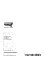
iB6 & iB12 Integrated Temperature Controller User Guide smart hot runner solutions www.mastip.com Temperature Controller iB6 / iB12 1.0 Introduction Precautions WARNING Use of this equipment in a manner not specified by the manufacturer may impair protection provided by the equipment. In addition to presenting a potential fire hazard, high voltage and high temperature can damage equipment and cause severe injury or death. When installing or using this instrument, follow all instructions carefully and use approved safety controls. Hazardous potentials exist on components inside the controller. Always disconnect AC power to the mainframe when servicing the controller. Because these temperature controls or associated equipment may not always fail safe, an approved temperature and/or pressure safety control should be used for safe operation. Turn off power to the controller before cleaning the exterior of the controller. Failure to observe these precautions can result in exposure to a potentially lethal shock hazard. All wiring should be done by an experienced technician. The controller and wiring should be installed in accordance with national and local electrical codes. To avoid serious personal injury and damage to equipment, follow all warnings and cautions provided in the hardware setup instructions. CAUTION If a controller shows signs of having been damaged during shipping, do not power up or install the controller. Save all packing materials and report any damage to the carrier immediately. Do not locate this instrument where it may be subjected to excessive shock, vibration, dirt, moisture, oil, or other liquids. This is a Class A product. In domestic environment this product may cause radio interference in which case the user may be required to take adequate measures. Specified operating ambient temperature is 0 to 50 °C (32 to 122 °F). © Copyright Mastip Technology Limited. Information subject to alteration. V1.02 www.mastip.com 3 1.0 Introduction iB6 / iB12 Temperature Controller Table of Contents 4 pg Contents 6 6 6 9 10 12 12 13 14 14 15 15 16 18 18 18 18 18 19 20 20 20 21 22 24 25 26 29 29 29 30 31 32 32 32 33 33 33 1.0Introduction 1.1 About this User Guide 1.2 iB6 & iB12 Features and Benefits 1.4 What Happens When You Power Up the Controller 2.0 Setup Sequence 3.0 User Interface 3.1 Overview 3.2 LED Status and Button Functions 3.3 Selecting One or All Zones 3.4 Mode of Operation 3.5 Changing the Setpoint 3.6 Changing a Configuration Parameter Value 3.7 Configuration Menus and Factory Settings 4.0 Alarms and Alarm Indication 4.1 Types of Alarms 4.2 Alarm Indication 4.3 Silencing Alarm Beep 4.4 External Indication 4.5 Alarm Priorities 5.0 Parameter Characteristics 5.1 Introduction 5.2 Input Parameters 5.3 Boost Parameters 5.4 Control Parameters 5.5 Display Units 5.6 Alarm Parameters 5.7 Supervisor Parameters 6.0 PID Controller Tuning 6.1 Introduction 6.2 Procedure for Autotuning 6.3 Autotune Errors 6.4 Manual Tuning (Zeigler-Nichols PID Method) 7.0 Restricting Access to Controller Functions 7.1 Introduction 7.2 Procedure 8.0 Resetting Parameters to the Default Values 8.1 Introduction 8.2 Procedure © Copyright Mastip Technology Limited. Information subject to alteration. V1.02 www.mastip.com Temperature Controller iB6 / iB12 1.0 Introduction Table of Contents pg Contents 34 34 35 36 37 38 39 40 41 42 9.0 Wiring 9.1 CE 16 Pin Female Power Connector for iB6 9.2 CE 16 Pin Male Thermocouple for iB6 9.3 US Domestic 25 Pin Female Power Connector 10A Max for iB6 9.4 US Domestic 25 Pin Male Thermocouple Connector for iB6 9.5 CE 24 Pin Female Power Connector for iB12 9.6 CE 24 Pin Male Thermocouple Connector for iB12 9.7 US Domestic 25 Pin Female Power Connector 10A Max for iB12 9.8 US Domestic 25 Pin Male Thermocouple Connector for iB12 10.0Index © Copyright Mastip Technology Limited. Information subject to alteration. V1.02 www.mastip.com 5 1.0 Introduction iB6 / iB12 Temperature Controller 1.1 About this User Guide This user guide contains all the information needed to configure and operate the iB6 and iB12 Integrated Temperature Controllers. Wiring diagrams, mounting instructions and other information about installing the hardware are on the installation diagrams shipped with the unit. 1.2 iB6 & iB12 Features and Benefits 1.2.1 Multi-Zone Control with Convenient User Interface A single iB6 Temperature Controller can provide microprocessor-based control of up to six zones; a single iB12 Hot Runner controller can control up to twelve zones. Zones can be configured individually or all zones can be configured simultaneously. During operation the front panel simultaneously displays the process value and setpoint for every zone. LEDs for each zone indicate the type of control (open or closed loop), output status, alarm status, boost status and standby status. Buttons on the front panel make it easy to change the setpoint, mode and configuration parameter values for one selected zone or all zones. The front panel also has buttons to: • start the boost for all zones, • put all zones in Idle or all Idle zones in the Run state, • silence the audible alarm. When necessary, access to function buttons on the front panel can be restricted. Refer to Section 7. for details on how to enable or disable functions. PV SP 285 251 250 60% 250 250 1 2 3 252 250 250 250 249 250 4 5 6 F C iB6 Operating Display PV 285 251 250 SP 60% 250 250 252 250 250 250 249 250 PV 285 251 250 SP 60% 250 250 252 250 250 250 249 250 iB12 Operating Display 6 © Copyright Mastip Technology Limited. Information subject to alteration. V1.02 www.mastip.com Temperature Controller 1.2.2 iB6 / iB12 1.0 Introduction PID Control with Autotuning When an iB6 or iB12 zone is in Normal (closed loop) mode, Proportional-Integral-Derivative (PID) control is provided. The iB6 and iB12 Temperature Controllers also support Manual (open loop) mode that overrides automatic control. In Manual mode you control the output by entering a fixed output percentage value.1 A zones transfer from PID to manual is “bumpless” when the process value is within 5 °C (9 °F) of the setpoint. Using PID control, the controller modulates output power by adjusting the output power percentage within a configurable proportional band. Power is proportionally reduced as the process temperature gets closer to the setpoint temperature. The configurable derivative action affects the output based on the rate of change of the process value. The integral action affects the output based on the duration of the process value’s variation from the setpoint. In the iB6 and iB12 Temperature Controllers, the integral (reset) action is always equal to six times the configured derivative (rate) action. An Autotune function is standard on every iB6 and iB12 Temperature Controller. This feature for easy tuning of the proportional and derivative, components of the control algorithm can be initiated every time the controller is powered up, once when the controller is set up regardless of success (and again by changing a parameter value), once only if successful (repeated at each power up until successful), or never. Instructions for tuning the controller automatically and manually are in Section 6. 1.2.3CompuStep® Soft Start for Heater Bake Out All iB6 and iB12 Temperature Controllers support the CompuStep® soft start feature, which allows slow dissipation of moisture in heaters by gradually applying power to the heaters. Using this feature helps extend the life of the heaters and the moulds. When a soft start is executed, single cycle bursts start at 5% output power and step up the output 5% every 30 seconds. • The soft start when the controller is in Normal (closed loop) mode lasts five minutes or until the process temperature reaches 93 °C (200 °F). • The soft start when the controller is in Manual (open loop) mode continues until the output is the lower of 50% or the target Manual mode output percent. By default, a soft start will be executed: • Every time the controller starts (after being taken out of Idle) and the process value is less than 93 °C (200 °F), and • Every time the controller is returned to Normal (automatic) operation and the PV is less than 93°C (200 °F). Use of a fixed output percentage is also possible under other circumstances. Configuration parameters let you specify a fixed output to be used as a failsafe action, a different fixed output percentage to be used in standby mode, and another fixed output percentage used during the boost function described in 1.2.4. 1 © Copyright Mastip Technology Limited. Information subject to alteration. V1.02 www.mastip.com 7 1.0 Introduction 1.2.4 iB6 / iB12 Temperature Controller Programmable Boost Function Every iB6 and iB12 Temperature Controller supports a boost function. For each zone you can use the Boost Config menu to configure a special setpoint (closed loop boost) or a special fixed output percentage (open loop boost) to be used when the boost button is pressed. The boost function will remain active until: • the configured boost duration time has expired, or • you use the mode/enter button to take a zone out of boost mode before the expiration of the boost duration. 1.2.5 Process-Protection Features Process-protection features are standard on all iB6 and iB12 controllers. These features include: • • • • high and low deviation alarms high temperature safety limit loop break detection failsafe operation in case of sensor problems 1.2.6Security The iB6 and iB12 front panels include buttons that can be used to change the selected zones setpoint and mode and to boost the output temporarily by a configurable amount. Users who know the Supervisor password can limit access to these buttons on the front panel, plus limit configuration access. (Units are shipped with password protection disabled.) 8 © Copyright Mastip Technology Limited. Information subject to alteration. V1.02 www.mastip.com Temperature Controller iB6 / iB12 1.0 Introduction 1.4 What Happens When You Power Up the Controller When an iB6 or iB12 Temperature Controller is powered up using the switch on the back, all LEDs and all elements in the LCD display light briefly, and then software versions (of the display and the controller hardware) are displayed. At the conclusion of the startup process, the process values and setpoints for all zones are displayed. Only the green LED for the display unit of measure (Celsius or Fahrenheit) is lit. All zone outputs will be off because the unit starts up with all zones in the Idle state. Briefly pressing the run/idle button on the front of the case puts all zones that are currently Idle in the Run state. (Pressing the button again for at least two seconds puts all zones in Idle.) In each zones column of LEDs, the green LED in the closed loop indicate the type of control. The green LEDs in the output or open loop row is lit to row indicate whether the zones outputs are on (LED lit) or off. For more information about the user interface, see the Section 3. When zones go into the Run state, the effect on each zones output depends on the value of the Startup Mode parameter configured using the Control Config menu. Refer to 5.4 for Startup Mode parameter details © Copyright Mastip Technology Limited. Information subject to alteration. V1.02 www.mastip.com 9 2.0 Setup Sequence iB6 / iB12 Temperature Controller 2.1 Setup Sequence The following list summarises the configuration and startup tasks to be accomplished once the controllers are wired as shown on the diagrams shipped with the unit. Refer to Section 5 for information about all configuration parameters, parameter interactions and valid ranges. 1) Turn on the controller using the switch on the back (shown below). When the unit is powered up, the controller goes through its startup sequence (see 1.4), and then the process value and setpoint for every zone (the standard operating display) are shown. All zones will be Idle (all outputs off). If the controller has already been wired to the sensors and heaters, do NOT push the run/idle button on the front of the case until after you have configured the zones and entered custom setpoints. When zones are taken out of Idle, their outputs may go on unless you change the default parameter values. 2) Take unneeded zones out of service by setting them to Offline. a) Select a zone by pressing the zone selection button until only that zones PV and SP are displayed. (Zone numbers are above the column of status LEDs for each zone.) b) Access the mode-selection function by pressing the mode/enter button c) Step through the possible modes by pressing the is displayed. d) Exit the mode-selection function by pressing the menu-access/exit button . A confirmation message will be displayed briefly and then the PV and SP for the zone will be displayed as “OFF.” . button repeatedly until “Offline” 3) Notice that the green C (for Celsius) or F (for Fahrenheit) LED is lit. This LED indicates the unit of measure for the process values and setpoints displayed. If you want to change the unit of measure used for temperature displays: a) With any zone selected, press and hold the menu-access/exit button a configuration menu is displayed. until the name of b) Step through the menus by pressing displayed. c) To access the Display Units parameter, press . The currently selected unit of measure will alternate with the parameter name on the lower line of the display. Notice that an asterisk is displayed instead of a zone number. This asterisk indicates that the parameter applies to all zones. repeatedly until the Display Config menu name is * 10 © Copyright Mastip Technology Limited. Information subject to alteration. V1.02 www.mastip.com Temperature Controller 2.0 Setup Sequence iB6 / iB12 d) Change the unit of measure by pressing e) Exit the menu system by pressing and holding for several seconds. The PV and SP for all zones (except any offline zones) will be displayed in the selected unit of measure. Other temperature values previously entered while a different unit of measure was in use will be converted automatically. or . 4) If the factory settings listed in subsection 3.6 are not appropriate for your application, you can change a parameter value for one or all zones. a) To select one zone, press repeatedly until only that zones PV and SP are displayed. To select all zones, press repeatedly until the PV and SP for all zones are displayed with asterisks between the PV and SP for zones 3 and 4 (refer to the image below) on an iB6 unit. (On an iB12 unit, asterisks will also be displayed between the PV and SP for zones 9 and 10.) 250 250 248 250 b) Press and hold c) Step through the menus by pressing is displayed. d) Step through the menu items by pressing alternating with its current value. e) Change the value by pressing or . When changing a numerical value, you can hold down an arrow button for fast changes. f) Exit the menu system by pressing and holding to enter the menu system. repeatedly until the name of the menu you want until the parameter you want is displayed, for several seconds. Note that the default High [Temperature] Safety [Limit] (a Supervisor parameter) is Off by default. If you want the controller to turn off the output to a zone that exceeds the high limit, change the value of the High Safety parameter. 5) iB6 and iB12 units are shipped with the Supervisor password set to 100, which disables password protection. If you want to limit access to the Superv [Supervisor] Config menu, change the Supervisor password from the default 100. As long as the password is 100, no password will be required to access all functions. 6) Change Normal mode (closed loop) setpoints or Manual mode (open loop) output percentage by selecting a zone, and then pressing or to change the setpoint or output percent. A few seconds after you stop pressing an arrow button, the main display (PV and SP) will return. Tip: If all zones are in the same mode (Normal or Manual), you can select all zones as described above, and then change the setpoint temperature or manual mode output percentage for all zones simultaneously. 7) Autotune all zones that will operate in Normal (closed loop) mode; see Section 6. When Autotuning has been completed successfully for all Normal zones, the controller is ready to use. The appropriate green status LED in the column of LEDs for each zone will be lit: for Normal (open loop) © Copyright Mastip Technology Limited. Information subject to alteration. V1.02 www.mastip.com 11 3.0 User Interface iB6 / iB12 for Manual (closed loop) for Standby Temperature Controller If the zone is configured to start up in Idle after the run/idle button status LED will be lit. Whenever a zones output is on, its green output has been pressed, no LED is lit. 3.1 Overview During operation, the front panel contains a two-line display that displays the PV (process value) and SP (Normal (closed loop) mode setpoint or Manual (open loop) mode output percentage) for each zone during normal operation. Zone numbers are under the display. PV and SP values are displayed in the unit of measure (degrees C or degrees F) indicated by the lit green “C” or “F” LED. This display can also be used to view and change controller settings as described in subsection 3.5. Parameters are grouped into menus. An overview of the menus is in subsection 3.6 If a zone is in alarm, an alarm code alternates with the SP value. Alarm codes and priorities are listed in Section 4.5 PV SP 285 251 250 60% 250 250 1 2 3 252 250 250 250 249 250 4 5 6 F C iB6 Operating Display PV 285 251 250 SP 60% 250 250 252 250 250 250 249 250 PV 285 251 250 SP 60% 250 250 252 250 250 250 249 250 iB12 Operating Display 12 © Copyright Mastip Technology Limited. Information subject to alteration. V1.02 www.mastip.com Temperature Controller 3.0 User Interface iB6 / iB12 3.2 LED Status and Button Functions 3.2.1 LED Symbols A column of LEDs for each zone indicates statuses for the zone and its output. LED 3.2.2 Description LED Description Output: lit green when the zones output is on Open Loop: lit green when the zone is in an open loop mode, such as Manual or Open Loop Boost Boost: lit green when the zone is in Boost mode Standby: lit green when the zone is in an standby mode or Hardware Standby mode Closed Loop: lit green when the zone is in a closed loop mode, such as Normal, Closed Loop Boost, Normal Soft Start, etc. Alarm: flashes red when the zone is in alarm For more information about alarm indications, see Section 4.2. Button Functions Buttons provide access to all controller functions3. The purposes of the buttons are shown below. Button Description Button Description Increase Increase setpoint for the selected zone(s) and change parameter values Decrease Decrease setpoint for the selected zone(s) and change parameter values Select one zone or all zones Zone Silence alarms for a configurable number of seconds Mute Boost all zones Mode Boost Idle Change the mode for the selected zone(s) and step through menu tems Press briefly to put all idle zones in run state; press at least two seonds to put all zones in idle Menu Brief press to display modes of all zones; longer presses to enter menu system and then brief press to step through menus ³ The Superv [Supervisor] Config menu can be used to disable the Boost and mode buttons, and to prevent operators from changing the setpoint or configuration parameter values. © Copyright Mastip Technology Limited. Information subject to alteration. V1.02 www.mastip.com 13 3.0 User Interface iB6 / iB12 Temperature Controller 3.3 Selecting One or All Zones To select one zone, press repeatedly until only that zones PV and SP are displayed. To select all zones, press repeatedly until the PV and SP for all zones are displayed with asterisks between the PV and SP for zones 3 and 4 (see right) on an iB6, and between zones 3 and 4, and zones 9 and 10 on an iB12. 250 250 248 250 3.4 Mode of Operation 3.4.1 Viewing Current Mode The current mode of all zones and their output percentages can be displayed by briefly pressing the menu-access/exit button . Mode indicators and their meanings are listed in the next subsection. 3.4.2 Mode Indicators In addition to indicators for the selectable modes (see 3.4.3 and 3.4.4), additional mode indicators are displayed under special circumstances, such as when Autotune or soft start is active. The mode indicators are: HSB Hardware standby (external signal put whole controller on standby) NRM Normal (closed loop) NTU Normal auto tuning (Autotuning in process) NSS Normal soft start—Gradual warming if the process value is less than the lower of the setpoint or 93 °C (200 °F) NRB Normal mode boost (using configured boost setpoint) MAN Manual (open loop) MAB Manual mode boost (using configured boost percentage) SBY Standby (using configured standby setpoint in Normal mode or fixed output percent in Manual mode) SSS Standby soft start—If zone is set to start up in Standby, it will gradually warm to the Standby setpoint if process value is less than the lower of the Standby setpoint or 93 °C (200 °F). Idle (no output) IDL FSF OFF 3.4.3 Failsafe (in state configured using Superv [Supervisor] menu) Offline (unused zone) Changing Mode To change mode of operation: 1) Select one zone or all zones as described above. 2) Access the mode-selection function by pressing . 3) Step through the selectable modes (refer to section 3.4.4) by pressing the until the mode you want is displayed. button repeatedly 4) Confirm the selection and exit the mode-selection function by pressing . A confirmation message will be displayed briefly, and then the normal operating display returns. 14 © Copyright Mastip Technology Limited. Information subject to alteration. V1.02 www.mastip.com Temperature Controller 3.4.4 iB6 / iB12 3.0 User Interface Modes Available for Selection The modes available for selection are: Normal Zone uses closed-loop PID automatic control based on the entered SP and measured PV Standby Zone uses Standby Setpoint or Standby Percentage as configured using the Control Config menu Manual Zone uses open-loop control; you set output percentage Boost For the configured Boost Duration time, the zone uses the Boost Setpoint or Boost Percentage configured with Boost Config menu. Idle Zones output is off until another mode is selected using the front panel OR — Offline Zones output is off and PV is not monitored by the controller is pressed to put all Idle zones in the Run state 3.5 Changing the Setpoint To change Normal mode (closed loop) setpoint or Manual mode (open loop) output percentage: 1) Select a zone or, if all zones are in the same mode (Normal or Manual), select all zones as described in subsection 3.2. 2)Press or to change the setpoint or output percent.4 A few seconds after you stop pressing an arrow button, the main display (PV and SP) will return. 3.6 Changing a Configuration Parameter Value To view and change parameter values: 1) Select one zone or all zones as described in subsection 3.2. 2) Press and hold to enter the menu system. 3) Step through the menus by pressing repeatedly until the name of the menu you want is displayed. Notice that if you selected all zones before entering the menu system (or if the parameter, such as Display Units, applies to all zones), an asterisk is displayed instead of a zone number. This asterisk indicates that the change will apply to all zones. * 4) Step through the menu items by pressing alternating with its current value. 5) Change the value by pressing arrow button for fast changes. or until the parameter you want is displayed, . When changing a numerical value, you can hold down an To change the value of this parameter for a different zone, press the zone you want is displayed. repeatedly until the number of To change a different parameter for the selected zone, repeat steps 3 through 5 as needed. To leave the menu system, press and hold for several seconds. The Superv [Supervisor] Config menu can be used to disable the boost and mode buttons, and to prevent operators from changing the setpoint or configuration parameter values. 4 © Copyright Mastip Technology Limited. Information subject to alteration. V1.02 www.mastip.com 15 3.0 User Interface iB6 / iB12 Temperature Controller 3.7 Configuration Menus and Factory Settings The table below shows all configuration menus, the parameters in each menu, and the factory settings. Information about each parameter is in Section 5. At the factory, all zones settings are identical. When a parameter is accessed, the display of its name alternates with the display of its current value. Menu Parameters Factory Setting Input Config Bias 0° Low Setpoint Limit 0 °C (32 °F) High Setpoint Limit 537 °C (999 °F) Input Type Depends on input type specified when the unit was ordered Boost Type (applies only to zones running in Normal mode; zones running in Manual mode always use Boost Percentage; see below) Closed loop Boost Duration Boost Off Boost Setpoint 25 °C (77 °F) Boost Percentage 0 Standby Type Open Loop Standby Setpoint 25 °C (77 °F) Standby Percentage 0 Proportional Band 24 Derivative [PID rate] 7 seconds PID Autotune (when it will be performed) Once at next power-up, and then disabled, even if tuning was not successful Startup Mode (when zone is taken out of Idle with run/idle button ) Last Active Mode (most recent operating mode) Boost Config Control Config 16 © Copyright Mastip Technology Limited. Information subject to alteration. V1.02 www.mastip.com Temperature Controller Menu Parameters Factory Setting Display Config Display Units °C 6 Alarm Config Inhibit Seconds 0 (off) High Dev Setpoint [High Deviation] 17 °C (30 °F) Low Dev Setpoint [Low Deviation] 17 °C (30 °F) Alarm Silence Seconds 120 seconds—applies to all zones Set Superv. Password 100 = OFF (password protection disabled) - applies to all zones Fail Safe Action Auto Average (use a calculated output value based on output values that have typically successfully maintained the current setpoint for your process in the past; if no history of Normal mode operation, then output is set to zero) - applies to selected zone Low Reading Not applicable High Reading Not applicable High [Temperature] Safety [Limit] OFF - applies to selected zone Fail Safe FOP [Fixed Output Percent] 0 % - applies to selected zone Loop Break Time 300 seconds - applies to selected zone Soft Start (CompuStep® gradual warming) Enable - applies to all zones that are in Normal (closed loop) mode Mode Key Enable Enable - applies to all zones Boost Key Enable Enable - applies to all zones SP [Setpoint] Change Enable Enable - applies to all zones Config. Enable Enable - applies to all zones Reset PID Parameters No - applies to selected zone Load Defaults No - applies to selected zone (but all zones must be in Idle; changes take effect after power has been cycled) Superv. Config [Supervisor] 6 3.0 User Interface iB6 / iB12 Supplied as °F if sold in USA or when requested at time of purchase © Copyright Mastip Technology Limited. Information subject to alteration. V1.02 www.mastip.com 17 4.0 Alarms & Alarm Indication iB6 / iB12 Temperature Controller 4.1 Types of Alarms The iB6 and iB12 Temperature Controllers support high and low deviation alarms, configurable separately for each zone (see subsection 5.6). The unit also recognises process problems (such as loop break, reversed and open sensors, and process temperature exceeding configured safety limit) and problems with its own operation. 4.2 Alarm Indication When a zone is in alarm: • its red alarm LED flashes rapidly (Slow flashes mean an alarm was detected, but the problem does not affect operation now. For example, a zones red alarm LED flashes slowly if an open thermocouple is detected, but the zone is operating in Manual mode (in which no sensor value is used by the controller to calculate the output) • the alarm relay closes • a code for the type of alarm alternates with display of the setpoint (Normal mode or other closedloop mode such as closed-loop boost) or output percentage (Manual mode or other open-loop mode such as open-loop standby); and • unit beeps until the alarm condition is cleared or the zone is put in Idle mode or the alarm is silenced (refer to Section 4.3 below). 4.3 Silencing Alarm Beep You can temporarily silence the alarm beep by pressing the alarm silence button silenced for the configured number of seconds. (The default is 120 seconds.) . Beeping will be 4.4 External Indication An output on the back of the controller allows external devices (such as horns or lights) to be connected to the controller for alarm annunciation. For more information about this feature, see the diagrams shipped with the controller. This alarm output is not affected when the alarm silence button pressed. Pin on the front of the controller is Connection 1 Alarm Common 2 Alarm N.O. 3 Standby Switch 4 Standby Switch Ground 18 © Copyright Mastip Technology Limited. Information subject to alteration. V1.02 www.mastip.com Temperature Controller iB6 / iB12 4.0 Alarms & Alarm Indication 4.5 Alarm Priorities If a zone has more than one alarm condition, the code for the highest-priority alarm is displayed. Alarm priorities are in the table below. Priority Code Condition Controller Response How Alarm Is Cleared 1 OVt Internal overtemperature All outputs off Turn off controller; make sure fan and vents are not blocked; wait for controller to cool; turn on controller; if error recurs, contact technical support 2 ER1 or ER2 Problem with controller’s internal operation All outputs off Cycle power to controller; if error recurs, contact the Mastip technical support at [email protected] or your local distributor 3 TCr Reversed thermocouple detected Zone goes to configured failsafe state 4 SAF High-temperature safety limit exceeded (configured in Superv. Config menu; default is feature disabled) Zone output off if feature is enabled 5 TCo Open thermocouple detected Zone goes to configured failsafe state (configured in Superv. Config menu) 6 LPB Loop break detected Zone output off 7 HID High deviation alarm Zone output off 8 LOD Low deviation alarm Zone output on 9 Tu0 Tu3 Tu5 Tu8 Tu9 Autotuning error Zone output off Use button to put the zone in Idle as described in 3.4.3, and then after problem is fixed, put zone in Normal (closed loop) or Manual (open loop) mode Clears automatically when alarm condition clears Use button to put the zone in Idle as described in 3.4.3, and then after problem is fixed, try tuning again For more information about tuning and Autotuning errors, see Section 6. © Copyright Mastip Technology Limited. Information subject to alteration. V1.02 www.mastip.com 19 5.Parameter Characteristics iB6 / iB12 Temperature Controller 5.1 Introduction This section contains information about every configuration parameter, including valid ranges, control mode(s) to which the parameter applies and interactions among parameters. For an overview of configuration menus and parameters refer to Section 3.7. 5.2 Input Parameters 5.2.1Introduction You can use the Input Config menu to specify for the selected zone(s): • bias (if any) to be applied to the input, • setpoint range, and • input type 5.2.2 Input Parameters and Settings Name Applies to Open Loop Control Closed Loop Control All Zones Selected Zones Default Description & Interactions 0° Number of degrees that will be added to or subtracted from the measured process value before it is displayed Lowest and highest values that can be entered as setpoint (before bias is applied); also limits configurable range of boost setpoint and standby setpoint Bias –55 to 55 °C –100 to 100 °F Low Setpoint Limit 0 to 537 °C 32 to 999 °F 0 °C 32 °F High Setpoint Limit 0 to 537 °C 32 to 999 °F 537 °C 999 °F Input Type 20 Range/ Choices J Thermo K Thermo Input type specified when unit was ordered Switching to input type that does not match the type specified when the unit was ordered can cause small errors (1-5 degrees) in temperature measurements © Copyright Mastip Technology Limited. Information subject to alteration. V1.02 www.mastip.com Temperature Controller iB6 / iB12 5.0 Parameter Characteristics 5.3 Boost Parameters 5.3.1Introduction A boost button s on the iB6 and iB12 front panel. When you press be increased temporarily. , the output of a zones will You can use the Boost Config menu to specify: • whether the boost function will be closed loop (based on a setpoint) or open loop (based on a specified output percent) • boost setpoint and duration for closed loop boost • boost output percentage and duration for open loop boost 5.3.2 Boost Parameters and Settings Name Applies to Open Loop Control Closed Loop Control All Zones Selected Zones Boost Type Range/ Choices Default Description & Interactions Open Loop Closed Loop Closed Loop Type of control used after is pressed; applies only to zones running in Normal mode; zones running in Manual mode always use Closed Loop boost Boost Off Length of boost 25 °C 77 °F Setpoint used in Closed Loop boost 0 (off) Output percent used in Open Loop boost Boost Duration Boost Off 15 seconds 30 seconds 45 seconds 60 seconds 75 seconds 90 seconds 105 seconds 120 seconds Boost Setpoint Boost Percentage Low Setpoint Limit to High Setpoint Limit (from Input Config menu) 0 to 100% © Copyright Mastip Technology Limited. Information subject to alteration. V1.02 www.mastip.com 21 5.0 Parameter Characteristics iB6 / iB12 Temperature Controller 5.4 Control Parameters 5.4.1Introduction You can use the Control Config menu to specify how the selected zone(s) will be controlled: • at startup (after you have pressed the run/idle button to take the controller out of Idle), • during Normal operation, • when the button has been used to put the zone in Standby or when a zone configured to start up in Standby mode comes out of Idle, and • when an external signal has been used to put the whole controller in Hardware Standby. The Control Config menu is also used to specify whether and how often Autotuning (described in Section 6) is done. 5.4.2 Control Parameters and Settings Name Applies to Open Loop Control Closed Loop Control All Zones Selected Zones 22 Range/ Choices Standby Type Open Loop Closed Loop Standby Setpoint Low Setpoint Limit to High Setpoint Limit (from Input Config menu) Default Description & Interactions Open Loop Type of control used while the controller’s front panel buttons have been used to put the selected zone(s) in standby mode: closed loop (Standby Setpoint used) or open loop (Standby Percentage used) Note: When an external signal puts all zones in Hardware Standby mode, this Standby Type value is ignored. If a zone is closed-loop when the Hardware Standby signal is received, the configured Standby Setpoint is used. If a zone is open-loop when the Hardware Standby signal is received, the configured Standby Percentage is used. 25 °C 77 °F Setpoint used when zone is in closed loop standby mode © Copyright Mastip Technology Limited. Information subject to alteration. V1.02 www.mastip.com Temperature Controller Name Applies to iB6 / iB12 Open Loop Control Closed Loop Control All Zones Selected Zones Range/ Choices 5.0 Parameter Characteristics Default Description & Interactions Zero Output percent used when zone is in open loop standby mode Standby Percentage Proportional Band 1 to 537 °C 1 to 999 °F 13 °C 24 °F Width of the band below the setpoint within which the controller will modulate the output as the process value approaches the setpoint; Autotuning sets this value automatically; Refer to Section 6 Derivative (rate) 0.0 to 999 seconds 7 seconds Time period used by the derivative component of the control algorithm when analyzing load changes; Autotuning sets this value automatically; Refer to Section 6 The integral action for PID control is not configurable; the integral (reset) action is always equal to six times the configured derivative (rate) action. PID Autotune Disable Once (then disabled after successful Autotune) Enable (Autotunes every time controller is powered up) One Try Only (and then disabled, even if Autotune was not successful) One Try Only Whether and when Autotune should be done 0 to 100 % © Copyright Mastip Technology Limited. Information subject to alteration. V1.02 www.mastip.com 23 5.0 Parameter Characteristics Name Applies to Open Loop Control Closed Loop Control All Zones Selected Zones Startup Mode iB6 / iB12 Range/ Choices Default Auto (Normal closed loop) Standby Manual (open loop) Idle (remains in Idle after is pushed to set controller to Run state) Last Active Mode (same mode as last time controller was running) Temperature Controller Description & Interactions Mode used for the zone when the controller goes from Idle to Run (because operator pushed on the front of the case) 5.5 Display Units 5.5.1Introduction On the front panel the lit green LED labeled C or F indicates the units of measure for the process values and setpoints displayed. You can use the Display Config menu to change the unit of measure used for displayed temperatures. 24 © Copyright Mastip Technology Limited. Information subject to alteration. V1.02 www.mastip.com Temperature Controller 5.5.2 iB6 / iB12 5.0 Parameter Characteristics Display Parameter and Settings Name Applies to Open Loop Control Closed Loop Control All Zones Selected Zones Display Units Range/ Choices °C °F Default Description & Interactions °C 7 Unit of measure used for all zones for all displayed temperatures, including parameter values; changing Display Units causes all temperatures already entered as parameter values or setpoints to be converted to the newly selected unit of measure when displayed 5.6 Alarm Parameters 5.6.1Introduction High and low deviation alarms are supported for each zone. (Section 4 contains information about alarm indication and effects on outputs.) You can use the Alarm Config menu to specify for the selected zone(s): • how many seconds after zone is taken out of Idle the controller should wait before indicating a low alarm (Alarm Inhibit) • number of degrees the process value must exceed the setpoint before the zone goes into alarm (High Deviation) • number of degrees the process value must fall short of the setpoint before the zone goes into alarm (Low Deviation) • the number of seconds the audible alarm on the iB6 or iB12 unit will be silenced when (on the front of the controller’s case) is pressed; this value applies to ALL zones in alarm. 7 Supplied as °F if sold in USA or when requested at time of purchase © Copyright Mastip Technology Limited. Information subject to alteration. V1.02 www.mastip.com 25 5.0 Parameter Characteristics 5.6.2 iB6 / iB12 Temperature Controller Alarm Parameters and Settings Name Applies to Open Loop Control Closed Loop Control All Zones Selected Zones Range/ Choices Default Description & Interactions Inhibit Seconds 0 to 999 seconds 0 (off) Number of seconds the controller should wait after zone is taken out of Idle before signaling a low alarm High Dev Setpoint 1 to 537 °C 1 to 999 °F 17 °C 30 °F Number of degrees the process value must exceed the setpoint to trigger the alarm state Low Dev Setpoint 1 to 537 °C 1 to 999 °F 17 °C 30 °F Number of degrees the process value must fall below the setpoint to trigger the alarm state 120 seconds Number of seconds the audible alarm on the controller will be silenced when is pressed. Alarm Silence Seconds 0 to 600 seconds 5.7 Supervisor Parameters 5.7.1Introduction You can use the Superv [Supervisor] Config menu to specify the values of several parameters related to process protection for the selected zones. You can also use this menu to set up parameters that apply to the whole controller. The Superv Config menu can be password protected. iB6 and iB12 Temperature Controllers are shipped with the Supervisor password set to 100, which disables this feature. You can use this menu to specify a different password. Only users who know your new three-digit password will be able to view and change parameters in the Superv Config menu. 26 © Copyright Mastip Technology Limited. Information subject to alteration. V1.02 www.mastip.com Temperature Controller 5.7.2 iB6 / iB12 5.0 Parameter Characteristics Supervisor Parameters and Settings Name Applies to Open Loop Control Closed Loop Control All Zones Selected Zones Set Superv. Password Range/ Choices 100 to 999 Default Description & Interactions 100 = Off Password needed to access parameters in Superv [Supervisor] Config menu Fail Safe Action Off Auto Average Fixed Output Pct. Auto Average Output action to be used when controller detects an open or reversed sensor: off, automatically calculated based on past good output values (if no history of Normal mode output values, then zero), or failsafe fixed output percent Low Reading — — Lowest process value for selected zone since the last time the reading was reset by pressing the up or down arrow button High Reading — — Highest process value for selected zone since the last time the reading was reset by pressing the up or down arrow button High Safety (High Temperature Safety Limit) 1 to 537 °C 33 to 999 °F OFF Output will be turned off if process value reaches this temperature Fail Safe FOP (fixed output percentage) 0% Output percent used only if open or reversed sensor is detected and Fail Safe Action is set to Fixed Output Pct. Loop Break Time (sec.) OFF 10 to 999 seconds 300 seconds Time period during which the input should change 1% of supported sensor span (5.37 °C or 9.67 °F) in response to output action if the sensor is working correctly and the input wiring is intact 0 to 100% © Copyright Mastip Technology Limited. Information subject to alteration. V1.02 www.mastip.com 27 5.0 Parameter Characteristics 5.7.2 Temperature Controller Supervisor Parameters and Settings Name Applies to Enable Gradual increase of output to slowly dissipate moisture in heaters; refer to 1.2.3 Mode Key Enable Disable Enable Enable Boost Key Enable Disable Enable Enable Enables/disables SP Change Enable Disable Enable Enable Enables/disables use of front panel buttons to change Normal mode setpoint and Manual mode output percentage Config. Enable Disable Enable Enable Enables/disables use of front panel buttons to change configuration parameter values Open Loop Control Disable Enable Closed Loop Control Description & Interactions All Zones Default Selected Zones Range/ Choices Soft Start 28 iB6 / iB12 Enables/disables button button Reset PID Parameters Yes No No Return tuning parameters to their default settings, undoing Autotuning or manual tuning Load Defaults Yes No No Return configuration parameter values to their default settings as described in Section 8.0 © Copyright Mastip Technology Limited. Information subject to alteration. V1.02 www.mastip.com Temperature Controller iB6 / iB12 6.0 PID Controller Tuning 6.1 Introduction iB6 and iB12 Temperature Controllers support automatic tuning for control of zones running in CompuCycle Normal (closed loop) mode. By default, every iB6 and iB12 controller is configured to execute the Autotune operation the first time it is powered up, then to disable the Autotune feature, even if Autotune was not successful. The Autotune operation overwrites any existing proportional band and derivative (rate) parameter values that were previously configured. All iB6 and iB12 controllers in a single process should be Autotuned simultaneously, so that interactions between zones during tuning parallel the interactions expected while the controllers are in use. Typical Autotune PV Profile SV Heat Storage Test Heat On Heat Off Heat On Response Test Starting Conditions Test 6.2 Procedure for Autotuning To Autotune: 1) Make sure the controller is in Idle state (only the green C or F LED lit). 2) After configuring any parameters that you want to change from the defaults, enter a setpoint that is representative of the setpoint you expect to use when the selected zones are in Normal mode operation. 3) If Autotuning has been attempted in the past, the Autotune feature may be disabled. To force an Autotune operation, use the Control Config menu to set the PID Autotune parameter to Enable. 4) Cycle the power to the controller. 5) At this point the controller may execute a CompuStep® soft start. • If you want the soft start to continue to its normal conclusion (recommended), do not press any buttons. • If you want to terminate the soft start (not recommended), use the mode button to set the selected zones mode to Normal. © Copyright Mastip Technology Limited. Information subject to alteration. V1.02 www.mastip.com 29 6.0 PID Controller Tuning iB6 / iB12 Temperature Controller During the Autotune operation, the display for the selected zones blinks “Tun.” Unless you want to terminate the Autotune by changing a zones mode, do not press any buttons during the Autotune operation. The lower line will continue to display the setpoint you entered in Step 2. When the controller has completed Autotuning a zone successfully, the controller will save the tuning parameter values in the Proportional Band and Derivative (rate) parameters for all zones that have Autotuned successfully. (The new tuning values can be viewed using the Control Config menu.) If Autotune was unsuccessful for a zone, the zone will: • use default values for PID parameters, • go into alarm (red LED lit in the row), • display its process value alternating with one of the tuning error codes listed in 6.3, and • go to configured failsafe state; the effect on a zones output depends on how you configured the Fail Safe Action parameter in the Superv [Supervisor] Config menu. To clear the error display and put the zone(s) in standby mode, use the mode button . (The effect on each zones output depends on the standby configuration selections you made using the Control Config menu.) Fix the problem (see error code meanings in next subsection) and try tuning again. Once Autotune has been completed successfully for all Normal zones (“NRM” mode displayed) use the Control Config menu to disable PID Autotune. 6.3 Autotune Errors The Autotune error codes are in the table below. 30 Error Code Description Tu3 Setpoint is lower than the process value. Look at the setpoint. If it is realistic for your process, then check the thermocouple leads; maybe they are reversed. Tu5 The initial process value and the setpoint are not far enough apart. For Autotune to work, the difference must be at least 5 °C (9 °F). Tu8 The startup curve (change in PV) was not acceptable to the Autotune algorithm. This problem could be caused by a process upset that occurred during tuning. Try Autotuning again when the process is stable. If the error recurs, your process is not suitable for Autotuning. Use manual tuning as described in 6.4. Tu9 The Autotuning timed out, because the process was unresponsive (or extremely slow to respond). Your process is not suitable for Autotuning. Tune the controller manually as described in 6.4. Tun0 The Autotune operation failed for a reason other than those listed above. Try Autotuning again when the process is stable. © Copyright Mastip Technology Limited. Information subject to alteration. V1.02 www.mastip.com Temperature Controller iB6 / iB12 6.0 PID Controller Tuning 6.4 Manual Tuning (Zeigler-Nichols PID Method) 6.4.1Introduction This tuning method may be used if the spread between initial process temperature and process operating temperature is small, or if the process is too slow for Autotuning. Manual tuning requires that zones be tuned one at a time and that the PV be tracked over time. (Graph the displayed PV against time manually.) All zones should be running while manually tuning one zone. After you have finished manual tuning, you can change the Startup Mode parameter setting and enable soft start (recommended). 6.4.2Procedure To do manual tuning: 1) After configuring any parameters that apply to your control strategy, enter a setpoint that is representative of the setpoint you expect to use when the selected zone is in Normal operation. 2) Go to the Control Config menu. 3) For now, leave the Proportional Band set to 13 °C (24 °F), but change the Derivative (PID rate) to 0 seconds. 4) In the Control Config menu, set the PID Autotune parameter to Disable. 5) Return to the standard operating display and watch the behavior of the displayed process value. When the temperature reaches setpoint, plot a graph of the displayed process value against time or record the time period between temperature peaks. (Be patient. It may be several minutes before you see up and down changes (oscillation) in the process value for a manifold zone.) 6) If the temperature (process value) will not oscillate, then decrease the proportional band value by repeatedly halving the value (dividing it by 2) until a small, sustained temperature oscillation is seen. Alternatively, if the temperature (process value) oscillates severely, double the proportional band value (multiple it by 2) repeatedly until a small, sustained temperature oscillation is observed. 7) Measure the period in seconds of one cycle of oscillation (“T” on the diagram below). T 8) Divide the period of oscillation (T) by 8. The resulting number (quotient) is the correct Derivative parameter value (rate) time in seconds. 9) Access the Control Config menu and enter the Derivative value obtained in Step 8. The integral time will be set automatically to 6 times the rate. (You cannot view the integral term value.) 10) If the process is stable, manual tuning is completed. However, if slight oscillation is observed, multiply the current proportional band value by 1.66 and enter the product as the new PID Proportional Band value to complete the tuning procedure for this zone. © Copyright Mastip Technology Limited. Information subject to alteration. V1.02 www.mastip.com 31 7.0 Restricting Functions iB6 / iB12 Temperature Controller 7.1 Introduction If you have access to the Superv [Supervisor] Config menu, you can disable any of the following: the soft start feature (not recommended), boost button , mode button , use of the front-panel buttons to change setpoints or configuration parameters. 7.2 Procedure To disable/enable a button or function: 1) Select any zone by pressing . 2) Access the menu system by pressing until a menu name is displayed, and then press repeatedly until the name of the Superv Config menu is displayed. 3) Step through the parameters by pressing to disable is displayed. repeatedly until the name of the function you want 4) Choose “Disable” or “Enable” by pressing or 5) Exit the menu system by pressing and holding SP) is displayed. 32 . until the standard operating display (PV and © Copyright Mastip Technology Limited. Information subject to alteration. V1.02 www.mastip.com Temperature Controller 8.0 Resetting Default Values iB6 / iB12 8.1 Introduction Using this function returns all configuration parameter values for the selected zone(s) to their defaults (shown in Section 5). The setpoints for the selected zone(s) will be changed to 25 °C (77 °F). Reloading defaults never affects the following settings that apply to the whole controller: display units, input type. These settings that apply to the whole controller are not reset, even if all zones are selected before loading defaults. When all zones have been selected for resetting defaults, some settings that apply to the whole controller WILL be reset to the defaults shown in shown in Section 5. These values that are returned to the defaults include the Supervisor password (which will be reset to 100, disabling password protection) and access control settings described in Section 7. After loading defaults, you will need to cycle power to the controller before you can resume operation. 8.2 Procedure To load defaults to selected zones: 1) Put the controller in the Idle state by pressing for at least two seconds. (When the whole controller is in the Idle state, only the green C or F LED will be lit.) 2) Select the zone for which you want to load defaults by pressing until only that zones SP and PV are displayed. Alternatively, select all zones by pressing until all zones SP and PV are displayed with asterisks between the values for zones 3 and 4 (iB6), or between 3 and 4, and 9 and 10 (iB12). ** 3) Access the menu system by pressing until a menu name is displayed, and then press repeatedly until the name of the Superv Config menu is displayed. 4) Step through the parameters by pressing 5) Choose “Yes” by pressing or repeatedly until Load Defaults is displayed. . 6) Exit the menu system by pressing and holding until “Power Cycle the System” is displayed. 7) Cycle power to the controller. When powered up, the controller will use the default settings for the zone(s) selected in step 2. © Copyright Mastip Technology Limited. Information subject to alteration. V1.02 www.mastip.com 33 9.0 Wiring iB6 / iB12 Temperature Controller 9.1 CE 16 Pin Female Power Connector for iB6 Zone 1 2 3 4 5 6 6 Zone, 16 Pin Mould Connector Pin Number Connection 1 Power 9 Return 2 Power 10 Return 3 Power 11 Return 4 Power 12 Return 5 Power 13 Return 6 Power 14 Return Ground 34 © Copyright Mastip Technology Limited. Information subject to alteration. V1.02 www.mastip.com Temperature Controller 9.0 Wiring iB6 / iB12 9.2 CE 16 Pin Male Thermocouple for iB6 Zone 1 2 3 4 5 6 6 Zone, 16 Pin Mould Connector Pin Number Connection 1 Thermcouple + 9 Thermcouple - 2 Thermcouple + 10 Thermcouple - 3 Thermcouple + 11 Thermcouple - 4 Thermcouple + 12 Thermcouple - 5 Thermcouple + 13 Thermcouple - 6 Thermcouple + 14 Thermcouple Ground © Copyright Mastip Technology Limited. Information subject to alteration. V1.02 www.mastip.com 35 9.0 Wiring iB6 / iB12 Temperature Controller 9.3 US Domestic 25 Pin Female Power Connector 10A Max for iB6 1 A C Zone 1 2 3 4 5 6 2 3 4 5 6 7 8 9 B 6 Zone, 25 Pin Mould Connector Pin Number Connection A1 Power A2 Return A3 Power A4 Return A5 Power A6 Return A7 Power A8 Return B2 Power B3 Return B4 Power B5 Return Ground 36 © Copyright Mastip Technology Limited. Information subject to alteration. V1.02 www.mastip.com Temperature Controller 9.0 Wiring iB6 / iB12 9.4 US Domestic 25 Pin Male Thermocouple Connector for iB6 1 2 3 4 5 6 7 8 9 B Zone 1 2 3 4 5 6 A C 6 Zone, 25 Pin Mould Connector Pin Number A1 Connection Thermocouple + A2 Thermocouple - A3 Thermocouple + A4 Thermocouple - A5 Thermocouple + A6 Thermocouple - A7 Thermocouple + A8 Thermocouple - B2 Thermocouple + B3 Thermocouple - B4 Thermocouple + B5 Thermocouple Ground © Copyright Mastip Technology Limited. Information subject to alteration. V1.02 www.mastip.com 37 9.0 Wiring iB6 / iB12 Temperature Controller 9.5 CE 24 Pin Female Power Connector for iB12 Zone 1 2 3 4 5 6 7 8 9 10 11 12 12 Zone, 24 Pin Mould Connector Pin Number Connection 1 Power 13 Return 2 Power 14 Return 3 Power 15 Return 4 Power 16 Return 5 Power 17 Return 6 Power 18 Return 7 Power 19 Return 8 Power 20 Return 9 Power 21 Return 10 Power 22 Return 11 Power 23 Return 12 Power 24 Return Ground 38 © Copyright Mastip Technology Limited. Information subject to alteration. V1.02 www.mastip.com Temperature Controller 9.0 Wiring iB6 / iB12 9.6 CE 24 Pin Male Thermocouple Connector for iB12 Zone 1 2 3 4 5 6 7 8 9 10 11 12 12 Zone, 24 Pin Mould Connector Pin Number 1 Connection Thermocouple + 13 Thermocouple - 2 Thermocouple + 14 Thermocouple - 3 Thermocouple + 15 Thermocouple - 4 Thermocouple + 16 Thermocouple - 5 Thermocouple + 17 Thermocouple - 6 Thermocouple + 18 Thermocouple - 7 Thermocouple + 19 Thermocouple - 8 Thermocouple + 20 Thermocouple - 9 Thermocouple + 21 Thermocouple - 10 Thermocouple + 22 Thermocouple - 11 Thermocouple + 23 Thermocouple - 12 Thermocouple + 24 Thermocouple Ground © Copyright Mastip Technology Limited. Information subject to alteration. V1.02 www.mastip.com 39 9.0 Wiring iB6 / iB12 Temperature Controller 9.7 US Domestic 25 Pin Female Power Connector 10A Max for iB12 1 A C Zone 1 2 3 4 5 6 7 8 9 10 11 12 2 3 4 5 6 7 8 9 B 12 Zone, 25 Pin Mould Connector Pin Number Connection A1 Power A2 Return A3 Power A4 Return A5 Power A6 Return A7 Power A8 Return B2 Power B3 Return B4 Power B5 Return B6 Power B7 Return C1 Power C2 Power C3 Power C4 Return C5 Power C6 Return C7 Power C8 Return A9 Power C9 Return Ground 40 © Copyright Mastip Technology Limited. Information subject to alteration. V1.02 www.mastip.com Temperature Controller 9.0 Wiring iB6 / iB12 9.8 US Domestic 25 Pin Male Thermocouple Connector for iB12 1 2 3 4 5 6 7 8 9 B Zone 1 2 3 4 5 6 7 8 9 10 11 12 A C 12 Zone, 25 Pin Mould Connector Pin Number A1 Connection Thermocouple + A2 Thermocouple - A3 Thermocouple + A4 Thermocouple - A5 Thermocouple + A6 Thermocouple - A7 Thermocouple + A8 Thermocouple - B2 Thermocouple + B3 Thermocouple - B4 Thermocouple + B5 Thermocouple - B6 Thermocouple + B7 Thermocouple - C1 Thermocouple + C2 Thermocouple - C3 Thermocouple + C4 Thermocouple - C5 Thermocouple + C6 Thermocouple - C7 Thermocouple + C8 Thermocouple - A9 Thermocouple + C9 Thermocouple Ground © Copyright Mastip Technology Limited. Information subject to alteration. V1.02 www.mastip.com 41 10.0 Index A access control, 32, 33 alarm code displayed, 12, 18 Alarm Config menu, 17, 25, 26 alarm indication, 18, 19, 25 alarm LED, 18 alarm outputs, 18 alarm priorities, 19 alarm silence button, 13, 18 Alarm Silence Seconds parameter, 17, 25, 26 auto reset, 31 Auto Tuning mode, 7, 12, 14, 16, 23, 29 30, 31 Autotune errors,19, 30 Autotuning, 29 B Bias parameter, 16, 20 boost button, 8, 21, 32 Boost Config menu, 8, 15, 16, 21 Boost Duration parameter, 8, 15, 16, 21 boost function, 8, 21 Boost Key Enable parameter, 17, 28 Boost mode, 8, 13, 14 Boost Percentage parameter, 14, 15, 16, 21 Boost Setpoint parameter, 14, 15, 16, 20, 21 Boost Type parameter, 16, 21 bumpless transfer, 7 button functions, 13 C Celsius, 9, 10, 24 changing Manual mode output percent, 11, 28 changing parameter values, 13, 15 changing setpoint, 32, 33 CompuStep® soft start, 7, 17, 29 Config Enable parameter, 17, 28 Control Config menu, 9, 15, 16, 22, 29, 30, 31 D default settings (factory), 11, 16, 17 default settings, resetting to, 33 default values, restoring, 33 Derivative parameter, 7, 16, 23, 29, 30, 31 derivative, resetting, 27, 28 deviation alarms. See alarm Display Units, 9, 11, 15, 17, 24, 25, 33 E ER1 alarm, 19 ER2 alarm, 19 42 iB6 / iB12 Temperature Controller F Factory menu, 16 factory settings, 11, 16, 17 Fahrenheit, 9, 10, 24 Fail Safe Action parameter, 17, 27, 30 Fail Safe FOP parameter, 17, 27 failsafe state, 19, 30 FSF mode indicator, 14 H hardware installation instructions, where to find, 6 Hardware Standby mode, 13, 14, 22 HID alarm, 19 High Dev Setpoint parameter, 17, 25, 26 high deviation alarm message, 19 High Reading parameter, 17, 27 High Safety parameter, 11, 17, 19, 27 High Setpoint Limit parameter, 16, 20, 21, 22 high temperature safety limit. See High Safety parameter highest process value, 27 I IDL mode indicator, 14 Inhibit Seconds parameter, 17, 26 inhibiting alarms, 17, 26 input bias, 16, 20 Input Config menu, 16, 20, 21, 22 Input Config parameters, 20 input failure, 26, 27, 28 Input Type parameter, 16, 20, 33 installation instructions, where to find, 6 integral action, 23, 31 K keypad functions, 13 L LEDs, 13 Line Freq. parameter, 33 Load Defaults parameter, 17, 28 loading default values, 28, 33 LOD alarm, 19 loop break detected, 8, 19 Loop Break Time parameter, 17, 27 Low Dev Setpoint parameter, 17, 26 low deviation alarm message, 8, 18, 19, 25 Low Reading parameter, 17, 27 Low Setpoint Limit parameter, 16, 20, 21, 22 lowest process value, 17, 27 LPB alarm, 19 © Copyright Mastip Technology Limited. Information subject to alteration. V1.02 www.mastip.com Temperature Controller M MAN mode indicator, 14 Manual mode, 7, 11, 14, 15, 16, 18, 21, 28 Manual Mode Boost, 14 manual tuning procedure, 28, 30, 31 manual tuning, when required, 28, 30, 31 menu button, 13 mode button, 13, 15, 29, 30, 32 Mode Key Enable parameter, 17, 28 modes of operation, 14 N Normal mode, 11, 14, 15, 16, 17, 18, 21, 27, 28, 29 Normal Mode Boost, 14 Normal Soft Start mode, 13, 14 NRB mode indicator, 14 NRM mode indicator, 14, 30 NSS mode indicator, 14 NTU mode indicator, 14, 30 O OFF mode indicator, 14 offline zones, 11, 14, 15 open thermocouple detected, 18, 19 operating modes, 14 output failsafe value, 8, 14, 19, 27 output percents, displaying, 14 outputs, state on power up, 9 OVt alarm, 19 P parameter values, changing, 13, 15 password. See Supervisor password and Factory password PID Autotune parameter, 16, 23, 29, 30, 31 PID tuning parameters, 28, 30 power switch, 9, 10 powering up controller, 9 process value, highest, 17, 27 process value, lowest, 17, 27 Proportional Band parameter, 16, 23, 31 proportional band, resetting, 27, 28 Proportional-Integral-Derivativel. See PID R 10.0 Index iB6 / iB12 S SAF alarm, 19 safety information, 3 security access, 8 selecting zones, 14 sensor failure, 27, 28 Set Superv. Password parameter, 17, 27 silencing alarms, 13, 18 soft start, 7, 14, 17, 28, 29, 32 Soft Start parameter, 17, 28 SP Change Enable parameter, 17, 28 SSS mode indicator, 14 Standby mode, 14 Standby Mode parameter, 16 Standby Percentage parameter, 16, 23 Standby Setpoint parameter, 16, 20, 28 Standby Type parameter, 22 Startup Mode parameter, 17, 24 Superv Config menu, 26, 32, 33 Supervisor parameters, 17, 26, 27 Supervisor password, 8, 11, 17, 33 T TCo alarm, 19 TCr alarm, 19 Tu0 error, 19, 30 Tu3 error, 19, 30 Tu5 error, 19, 30 Tu8 error, 19, 30 Tu9 error, 19, 30 tuning, 29, 30 tuning errors, 19, 30 tuning parameters, 16, 22, 23, 27, 28, 30 U W unit of measure, 9, 10, 11, 12, 24, 25 unused zone, 10, 14 wiring diagrams, where to find, 6 rate action, 16, 22, 30, 31 rate, resetting, 27 Reset PID Parameters parameter, 17, 28 resetting highest and lowest process value reading, 27 reversed thermocouple, 19, 30 © Copyright Mastip Technology Limited. Information subject to alteration. V1.02 www.mastip.com 43 smart hot runner solutions Mastip Head Office New Zealand 558 Rosebank Road Avondale, Auckland 1026 PO Box 90-651 Victoria Street West Auckland 1142 New Zealand Phone: +64 9 970 2100 Fax: +64 9 970 2070 Email: [email protected] Mastip Regional Office Europe Phone: +33 4 724 72 800 Fax: +33 4 724 72 801 Email: [email protected] Mastip Regional Office China Phone: +86 21 644 77838 Fax: +86 21 644 77828 Email: [email protected] Mastip Regional Office North America Phone: +1 262 644 9400 Fax: +1 262 644 9402 Email: [email protected] 40-000-103 V1.02 *40-000-103*