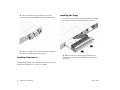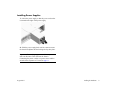
1
®
OmniSwitch 6900
Getting Started Guide
060333-10, Rev. A
August 2011
Attention.
Only personnel knowledgeable in basic electrical and mechanical procedures should install or maintain this equipment.
The features and specifications described in this guide are subject to change without notice.
Lithium Batteries Caution.
There is a danger of explosion if the lithium battery provided with the switch is incorrectly replaced. If a lithium battery
requires replacement for any reason, return the corresponding module to Alcatel-Lucent. The battery will be replaced
according to manufacturer specifications at an Alcatel-Lucent facility.
Copyright © 2011 by Alcatel-Lucent. All rights reserved. This document may not be reproduced in whole or in part
without the express written permission of Alcatel-Lucent.
OmniSwitch®, Alcatel-Lucent® and the Alcatel-Lucent logo are registered trademarks of Alcatel-Lucent. WebView™
is a trademark of Alcatel-Lucent.
Alcatel-Lucent
26801 West Agoura Road
Calabasas, CA 91301
(818) 880-3500 FAX (818) 880-3505
US Customer Support: (800) 995-2696
International Customer Support: (818) 878-4507
Internet: service.esd.alcatel-lucent.com
Table of Contents
OmniSwitch 6900 . . . . . . . . . . . . . . . . . . . . . . .
1
Your First Login Session . . . . . . . . . . . . . . . 12
Related Documentation . . . . . . . . . . . . . . . . . . . . . . . . . . 2
Logging In to the Switch . . . . . . . . . . . . . . . . . . . . . . . . 12
Setting IP Address Information for the EMP . . . . . . . . . 13
Installing the Hardware
............... 3
Items Required . . . . . . . . . . . . . . . . . . . . . . . . . . . . . . . . 3
Site Preparation . . . . . . . . . . . . . . . . . . . . . . . . . . . . . . . . 3
Unpacking and Installing the Switch . . . . . . . . . . . . . . . 4
Mounting the Switch . . . . . . . . . . . . . . . . . . . . . . . . . . . . 5
Rack Mounting . . . . . . . . . . . . . . . . . . . . . . . . . . . . . 5
Standalone (Non-Rack Mounted) Installations . . . . 6
Unlocking Session Types . . . . . . . . . . . . . . . . . . . . . . . . 14
Changing the Login Password . . . . . . . . . . . . . . . . . . . . 15
Setting the System Time Zone . . . . . . . . . . . . . . . . . . . . 15
Setting the Date and Time . . . . . . . . . . . . . . . . . . . . . . . 15
Setting Optional Parameters . . . . . . . . . . . . . . . . . . . . . 16
Viewing Your Changes . . . . . . . . . . . . . . . . . . . . . . . . . 16
Saving Your Changes . . . . . . . . . . . . . . . . . . . . . . . . . . 16
Installing Chassis Components . . . . . . . . . . . . . . . . . . . . 7
Using WebView . . . . . . . . . . . . . . . . . . . . . . . . . . 17
Connections and Cabling . . . . . . . . . . . . .
10
Ethernet Management Port (EMP) Cable Requirements 10
Booting the Switch . . . . . . . . . . . . . . . . . . . . . .
August 2011
Logging In to WebView . . . . . . . . . . . . . . . . . . . . . . . . 17
Navigating WebView . . . . . . . . . . . . . . . . . . . . . . . . . . 17
Troubleshooting WebView . . . . . . . . . . . . . . . . . . . . . . 18
11
iii
iv
August 2011
v
August 2011
OmniSwitch 6900
The Alcatel-Lucent OmniSwitch 6900 (OS6900) is a highcapacity, high-performance Ethernet LAN switch based on the
state-of-the-art Alcatel Operating System (AOS).
The OS6900’s class-leading low-power consumption, front-toback cooling, compact form-factor, and front-accessible
components make it a perfect fit for data center applications,
as well as a long-term upgrade for legacy core platforms.
OmniSwitch 6900
August 2011
OmniSwitch 6900
1
Related Documentation
The following user documentation is provided for the
OmniSwitch 6900.
• OmniSwitch 6900 Getting Started Guide
Describes the procedures for getting an OmniSwitch
6900 up and running. Also provides information on
fundamental aspects of hardware components and
basic setup commands.
• OmniSwitch 6900 Hardware Users Guide
Technical specifications and procedures for the
OmniSwitch 6900 chassis, power supplies, fans,
Chassis Management Modules (CMMs), Chassis
Fabric Modules (CFMs) and Network Interface (NI)
modules.
• OmniSwitch AOS Release 7 Network Configuration
Guide
Includes network configuration procedures and
descriptive information on all the major software
features and protocols included in the base software
package. Chapters cover Layer 2 information (Ethernet
and VLAN configuration), Layer 3 information
(routing protocols, such as RIP and VRRP), security
options (authenticated switch access), Quality of
Service (QoS), link aggregation, and server load
balancing.
• OmniSwitch AOS Release 7 Advanced Routing
• OmniSwitch AOS Release 7 CLI Reference Guide
Complete reference to all CLI commands supported on
the OmniSwitch 6900. Includes syntax definitions,
default values, examples, usage guidelines, and
CLI-to-MIB variable mappings.
• OmniSwitch AOS Release 7 Switch Management Guide
Includes procedures for readying an individual switch
for integration into a network. Topics include software
directory architecture, image rollback protections,
authenticated switch access, managing switch files,
system configuration, SNMP, and WebView
management software.
2
OmniSwitch 6900
Configuration Guide
Includes network configuration procedures and
descriptive information on advanced routing protocols
such as OSPF, BGP, DVMRP and PIM-SM.
• OmniSwitch AOS Release 7 Transceivers Guide
Includes information on Small Form Factor Pluggable
(SFP) and 10 Gbps Small Form Factor Pluggable
(SFP+) transceivers.
August 2011
Installing the Hardware
Items Required
• Grounding wrist strap (included)
• Phillips screwdriver
• Flat-blade screwdriver
• Serial cable
Site Preparation
Environmental Requirements
Electrical Requirements
OmniSwitch 6900 switches have the following general
electrical requirements:
• Each switch requires one grounded electrical outlet for
each power supply installed in the chassis.
OmniSwitch 6900 switches offer both AC and DC
power supply support. Refer to the OmniSwitch 6900
Hardware Users Guide for more information.
• For switches using AC power connections, each
supplied AC power cord is 2 meters (approx. 6.5 feet).
Do not use extension cords.
OmniSwitch 6900 switches have the following environmental
and airflow requirements:
• The installation site must maintain a temperature
between 0° and 45° Celsius (32° and 113° Fahrenheit)
and not exceed 85 percent maximum humidity (noncondensing) at any time.
• Be sure to allow adequate room for proper air
ventilation at the front, back, and sides of the switch.
Refer to “Mounting the Switch” on page 5 for
minimum clearance requirements. No clearance is
necessary at the top or bottom of the chassis.
August 2011
Redundant AC Power. It is recommended that each AC
outlet resides on a separate circuit. With redundant AC, if
a single circuit fails, the switch’s remaining power
supplies (on separate circuits) can remain operational.
• For switches using DC power, refer to the OmniSwitch
6900 Hardware Users Guide for more information.
Installing the Hardware
3
Unpacking and Installing the Switch
Lifting the Chassis
To protect your switch components from damage, read all
unpacking recommendations and instructions carefully before
beginning.
Lifting the chassis requires two people. When lifting, use the
recessed hand grip provided on the rear panel and the
reinforced area immediately under the front air intake plenum.
Unpack your OmniSwitch 6900 chassis as close as possible to
the location where it will be installed.
Items Included
Note. Lifting the OmniSwitch 6900 chassis improperly
can cause personal injury and/or damage to the unit.
Your OmniSwitch 6900 includes the following items:
• OmniSwitch chassis with power supplies, per order
• Transceivers, per order
• Blank cover panels, if applicable
• Grounding wrist strap
• DB9-to-RJ-45 adapter
• RJ-45-to-USB console adapter
• Country-specific power cord(s)
Weight Considerations
The empty OmniSwitch 6900 chassis weighs approximately
17 lbs (7.7 kgs). When fully populated (i.e., with components
installed in all available chassis slots), the OmniSwitch 6900
can weigh up to approximately 25 lbs (11.3 kgs).
4
Installing the Hardware
August 2011
Mounting the Switch
Airflow Considerations
To ensure proper airflow, be sure that your switch is placed in
a well-ventilated area and provide minimum recommended
clearance at the front, back and sides of the switch.
}
Rear. 6 inches minimum
at rear of chassis.
Rack Mounting
Refer to the following important guidelines before installing
the chassis in a rack:
• Three people are required to rack mount the switch:
Two people to lift the chassis into position and one
person to secure the chassis to the rack using the rack
mount screws.
Sides. 2 inches minimum
at left and right sides.
• The chassis has two integral rack-mount flanges that
support standard 19-inch rack mount installations.
• Alcatel-Lucent does not provide rack-mount screws.
Use the screws supplied by the rack vendor.
• To prevent a rack from becoming top heavy, it is
}
recommended that you install heavier equipment at the
bottom of the rack whenever possible.
Front. 6 inches minimum
at front of chassis.
Chassis Top View
• If you are installing the switch in a relay rack, be sure
to install and secure the rack per rack manufacturer’s
specifications.
Never obstruct the air intake vents located at the bottom-front
and bottom-sides of the chassis or the fan unit’s air output
vents located at the rear of the chassis.
Note. Clearance is not required at the top and bottom of
the chassis.
August 2011
Installing the Hardware
5
To rack mount the switch, follow the steps below.
1 Mark the holes on the rack where the chassis is to be
Standalone (Non-Rack Mounted)
Installations
installed.
2 Using two people, lift and position the chassis until the
rack-mount flanges are flush with the rack post. Refer to
page 4 for information on properly lifting the chassis.
The chassis can also be placed unmounted on a stable, flat
surface as a standalone unit. Be sure that the surface can
accommodate the full, populated weight of all switches
being installed. Approximate chassis weights are provided
on page 4.
3 Align the holes in the flanges with the rack holes
marked in step 1.
4 Once the holes are aligned, use a third person to insert
a screw through the bottom hole on each flange. Tighten
both screws until they are secure.
For a standalone unit, use two or more people to move and
position the unpopulated chassis upright on the surface
where it is to be installed. Be sure that adequate clearance
has been provided for chassis airflow and that you have
placed the chassis within reach of all required AC outlets.
For recommended airflow allowances, refer to page 5.
5 Once the screws at the bottom of each flange are
secure, install the remaining screws. Be sure that all
screws are securely tightened.
Optional Rack-Mounting Hardware
Note. Chassis must be placed “right side up.” Never
attempt to operate a switch while it is lying on its side or
back.
All OmniSwitch 6900 switches are shipped with integral front
rack mount flanges. These flanges support standard 19” rack
mount installations. If you have non-standard rack mount
requirements, contact your Alcatel-Lucent representative for
information on optional hardware availability.
6
Installing the Hardware
August 2011
Installing Chassis Components
1 Insert the module into the slot along the chassis card
guides. The component side of the board should face up.
The module should slide in easily.
Electrostatic Discharge (ESD) Notice. Be sure to follow
proper procedures to eliminate electrostatic discharge
(ESD) from your person and the surrounding area before
installing chassis components.
Blank Cover Plates
Blank cover plates are factory-installed in the chassis and are
used to cover empty slots. These cover plates play an
important role in chassis airflow and temperature management.
They also provide protection for electronics and other sensitive
internal switch components by closing off a chassis that is not
fully populated.
Because they regulate airflow and help protect internal chassis
components, blank cover plates should remain in place at all
times.
Installing Plug-in Modules
Before installing the plug-in modules in the chassis, locate
their slot positions in the chassis. Slot numbers are clearly
marked on the OmniSwitch 6900 front and rear panel.
To install a module, follow the steps below:
August 2011
Note. Do not force the module into the slot. If any
resistance is encountered, make sure the module is aligned
properly in the card guides.
2 When the module is nearly seated in the slot, be sure
that the extractor lever is pressed up. This allows the
notches on the extractor lever to grasp the rail on the
chassis.
Installing the Hardware
7
3 Once the notches have grasped the rail, press the
Installing Fan Trays
extractor lever upward until the module is firmly seated.
1 Insert the tray into the chassis slot and slide it straight
back until it meets the chassis backplane connectors.
4 Once the module is firmly seated, secure the module to
the chassis by tightening the captive screw.
2 When the fan tray is firmly seated, tighten the two
Installing Transceivers
captive screws at the left and right sides of the fan tray’s
front panel.
For detailed information on installing transceivers, refer to the
OmniSwitch AOS Release 7 Transceivers Guide.
8
Installing the Hardware
August 2011
Installing Power Supplies
1 Orient the power supply so that the power cord socket
is situated at the right of the power supply.
2 Slide the power supply back until its connector meets
the chassis backplane and the locking tab clips into place.
Important. Do not plug any power cords into a power
source at this time as this will boot the chassis.
Connecting the power cord(s) to a power source and the
switch’s boot sequence are covered on page 11.
August 2011
Installing the Hardware
9
Connections and Cabling
Once your switch is properly installed, you should connect all
network and management cables required for your network
applications. Connections may include:
• RJ-45 straight-through cable to the RJ-45-to-USB
console connector
• Ethernet cable to the Ethernet Management Port
(EMP) on the CMM
• Cables to NIs or transceivers
Serial Connection to the Console Port
The console port provides a serial connection to the switch
using a USB connector and is required when logging into the
switch for the first time. By default, this connector provides a
DCE console connection.
Serial Connection Default Settings
baud rate
9600
parity
none
data bits (word size)
8
stop bits
1
Ethernet Management Port (EMP)
Cable Requirements
There are specific cable type requirements (i.e., straightthrough or crossover) based on the location of the Ethernet
Management Port (EMP) and the type of device to which it is
connecting. Refer to the information below:
EMP to a Switch
Straight-through
EMP to a Computer or
Workstation
Crossover
For information on manually configuring Ethernet ports for
cabling requirements, refer to the OmniSwitch AOS Release 7
Network Configuration Guide.
For detailed information on all port types, including console,
EMP, Gigabit Ethernet, and 10 Gigabit Ethernet, refer to the
OmniSwitch 6900 Hardware Users Guide.
For information on modifying these settings, refer to the
OmniSwitch AOS Release 7 Switch Management Guide.
10
Connections and Cabling
August 2011
Booting the Switch
Now that you have installed the switch components and
connected network and management cables, you can boot the
switch. To boot the switch, plug all power supply cords into
easily-accessible, properly grounded power outlets. (Do not
use extension cords.) The switch will power on and boot
automatically.
Note. If you have more than one power supply installed,
be sure to plug in each power supply in rapid succession,
(i.e., within a few seconds of each other). This ensures that
there will be adequate power for all modules throughout
the boot process.
Power Supply AC
Green
Power Supply DC
Green
If the LEDs do not display as indicated, make sure the boot
process is completed. If the LEDs do not display as indicated
following a complete boot sequence, contact Alcatel-Lucent
Customer Support. For complete information on LED states,
refer to the OmniSwitch 6900 Hardware Users Guide.
Once the switch has completely booted and you have accessed
your computer’s terminal emulation software via the console
port, you are ready to log in to the switch’s Command Line
Component LEDs
During the boot process, component LEDs will flash and
change color, indicating different stages of the boot. Following
a successful boot, the LEDs on all switch components,
including power supplies, should display as follows:
OK
Green
PS
Amber - 1 PS
Green - 2 PS
EMP
Off - No Link
Green - Link
August 2011
Power Save
Features Active
Interface (CLI) and configure basic information. Continue to
“Your First Login Session” on page 13.
Booting the Switch
11
Your First Login Session
In order to complete the setup process for the switch, you must
complete the following steps during your first login session:
• Log in to the switch
• Set IP address information for the Ethernet
Management Port (EMP)
Logging In to the Switch
When you first log in to the switch, you will be prompted for a
CMM login name and password. Use the switch’s default
settings:
• CMM login: admin
• Password: switch
• Unlock session types
• Change the login password
• Set the date and time
• Set optional system information
The default welcome banner, which includes information such
as the current software version and system date, is displayed
followed by the CLI command prompt:
+++ WARNING! Switch Access Vulnerability.
• Save your changes
+++ WARNING! Admin user authentication using
default password.
Welcome to the Alcatel-Lucent OS6900
7.2.1.119.R01, June 15, 2011.
Important. You must be connected to the switch via the
console port before initiating your first login session.
Copyright (c) 1994-2011 Alcatel-Lucent. All
Rights Reserved.
OmniSwitch(tm) is a trademark of Alcatel-Lucent,
registered in the United States Patent and
Trademark Office.
->
12
Your First Login Session
August 2011
More Information On User Accounts. A user account
includes a login name, password, and user privileges.
Privileges determine whether the user has read or write
access to the switch and which commands the user is
authorized to execute. For detailed information on setting
up and modifying user accounts, refer to the OmniSwitch
AOS Release 7 Switch Management Guide
Setting IP Address Information for
the EMP
The Ethernet Management Port (EMP) is located on the CMM
module. The EMP allows you to bypass the Network Interface
(NI) modules and manage the switch over the network directly
through the CMM.
To change the default IP and mask, use the
ip interface command. For example:
-> ip interface emp address 168.22.2.120 mask
255.255.255.0
Verify your settings using the show ip interface command.
See the OmniSwitch AOS Release 7 Switch Management
Guide for additional information regarding EMP port
addressing.
Note. Although you have configured the EMP with valid
IP address information, you will not be able to access the
switch through this port (i.e. TELNET, FTP, HTTP, SSH
or SNMP) until you have unlocked these remote session
types. See “Unlocking Session Types” on page 14 for
more information.
To connect to the switch through the EMP Ethernet connection
use the default address below or change the port’s IP address if
desired.
Default EMP IP Address
10.255.24.81
Default EMP Mask
255.0.0.0
Note. You should be connected to the switch via the
console port before attempting to change IP address
information.
August 2011
Your First Login Session
13
Unlocking Session Types
Unlocking Specified Session Types
Security is a key feature on OmniSwitch 6900 switches. As
described on page 13, when you access the switch for the first
time, you must use a direct console port connection. All other
session types (Telnet, FTP, WebView, and SNMP) are locked
out until they are manually unlocked by the user.
You can also unlock session types on a one-by-one basis. For
example, to unlock Telnet sessions only, enter the following
command:
The CLI command used to unlock session types is
aaa authentication.
To unlock WebView (HTTP) sessions only, enter the
following command:
-> aaa authentication telnet local
-> aaa authentication http local
Note. When you unlock session types, you are granting
switch access to non-local sessions (e.g., Telnet). As a
result, users who know the correct user login and
password will have remote access to the switch. For more
information on switch security, refer to the OmniSwitch
AOS Release 7 Switch Management Guide.
Unlocking All Session Types
To unlock all session types, enter the following command
syntax at the CLI prompt:
You cannot specify more than one session type in a single
command line. However, you can still unlock multiple session
types by using the aaa authentication command in
succession. For example:
-> aaa authentication http local
-> aaa authentication telnet local
-> aaa authentication ftp local
Refer to the OmniSwitch CLI Reference Guide for complete
aaa authentication command syntax options.
-> aaa authentication default local
14
Your First Login Session
August 2011
Changing the Login Password
Setting the System Time Zone
Change the login password for admin user sessions by
following the steps below:
The switch’s default time zone is UTC. If you require a time
zone that is specific to your region, or if you need to enable
Daylight Savings Time (DST) on the switch, you can
configure these settings via the system timezone and
system daylight-savings-time commands.
1 Be sure that you have logged into the switch as user
type admin (see “Logging In to the Switch” on page 12).
2 Enter the keyword password and press Enter.
3 Enter your new password at the prompt.
For detailed information on configuring a time zone for the
switch, refer to the OmniSwitch AOS Release 7 Switch
Management Guide.
Note. Be sure to remember or securely record all new
passwords; overriding configured passwords on an
OmniSwitch is restricted.
Setting the Date and Time
4 You will be prompted to re-enter the password. Enter
To set the current date for the switch, enter system date,
followed by the current date in mm/dd/yyyy.
the password a second time.
Set the current time for the switch by entering system time,
followed by the current time in hh:mm:ss.
New password settings are automatically saved in real time to
the local user database; the user is not required to enter an
additional command in order to save the password
information. Also note that new password information is
retained following a reboot. All subsequent login sessions,
including those through the console port, will require the new
password to access the switch.
For detailed information on managing login information,
including user names and passwords, refer to the OmniSwitch
AOS Release 7 Switch Management Guide.
August 2011
Your First Login Session
15
Setting Optional Parameters
Viewing Your Changes
Specifying an Administrative Contact
To view your current changes, enter show system at the CLI
prompt.
An administrative contact is the person or department in
charge of the switch. If a contact is specified, users can easily
find the appropriate network administrator if they have
questions or comments about the switch.
To specify an administrative contact, use the system contact
command.
Saving Your Changes
Once you have configured this basic switch information, save
your changes by entering write memory at the CLI command
prompt.
Specifying a System Name
The system name is a simple, user-defined text description for
the switch. To specify a system name, use the system name
command.
Specifying the Switch’s Location
It is recommended that you use a physical labeling system for
locating and identifying your switch(es). Examples include
placing a sticker or placard with a unique identifier (e.g., the
switch’s default IP address) on each chassis.
However, if no labeling system has been implemented or if
you need to determine a switch’s location from a remote site,
entering a system location can be very useful.
To specify a system location, use the system location
command.
16
Your First Login Session
August 2011
Using WebView
OmniSwitches can be configured and monitored using
WebView, Alcatel-Lucent’s web-based device management
tool.
Navigating WebView
After you have successfully logged in, the Chassis
Management home page displays.
Logging In to WebView
Note. Before attempting to establish a WebView session,
be sure that you have first unlocked the HTTP session
type using the aaa authentication command. Otherwise, a
login error will occur. See “Unlocking Session Types” on
page 14 for more information.
To access WebView and log in to a switch:
1 Enter the switch’s IP address in your web browser. If a
certificate warning error occurs, accept the certificate and
allow the page to load. The login screen displays.
2 Next, enter the user name and password at the login
prompt.
The Chassis Management home page provides a physical
representation of the switch as well as basic system
information. This is the main launching point for WebView.
Note. For more information on using WebView, refer to
the OmniSwitch AOS Release 7 Switch Management
Guide.
August 2011
Using WebView
17
Troubleshooting WebView
The WebView login screen does not display.
This suggests either a physical or network connection issue.
Try the following options:
• Be sure that there is a good physical Ethernet cable
connection to the Ethernet port used for managing the
switch (EMP or NI port).
• Be sure your computer has a valid Ethernet connection
and IP address. See page 13 for information on
configuring the IP address for the EMP.
The login screen displays, but login attempts fail.
This suggests either a user name and password or
Authenticated Switch Access error. Try the following options:
• Check that you are using the correct user name and
password. If you have already changed the user name
and password for your switch, be sure to use the new
information. If you have not changed the user name
and password, the factory defaults are admin and
switch, respectively.
• Be sure that you have unlocked HTTP sessions on the
switch. To unlock HTTP sessions, enter the following
command:
-> aaa authentication http local
For more information on unlocking session types, see page 14.
18
Using WebView
August 2011