1
Part No. 060365-00, Rev. A
January 2013
OmniSwitch 6850E Series
Hardware Users Guide
www.alcatel-lucent.com
This user guide documents OmniSwitch 6850E Series hardware, including
chassis and associated components for the 6.4.5.R02 Release.
The specifications described in this guide are subject to change without notice.
Copyright © 2013 by Alcatel-Lucent. All rights reserved. This document may not be reproduced in whole
or in part without the express written permission of Alcatel-Lucent.
Alcatel-Lucent® and the Alcatel-Lucent logo are registered trademarks of Alcatel-Lucent. Xylan®,
OmniSwitch®, OmniStack®, and Alcatel-Lucent OmniVista® are registered trademarks of Alcatel-Lucent.
OmniAccess™, Omni Switch/Router™, PolicyView™, RouterView™, SwitchManager™, VoiceView™,
WebView™, X-Cell™, X-Vision™, and the Xylan logo are trademarks of Alcatel-Lucent.
This OmniSwitch product contains components which may be covered by one or more of the following
U.S. Patents:
•U.S. Patent No. 6,339,830
•U.S. Patent No. 6,070,243
•U.S. Patent No. 6,061,368
•U.S. Patent No. 5,394,402
•U.S. Patent No. 6,047,024
•U.S. Patent No. 6,314,106
•U.S. Patent No. 6,542,507
•U.S. Patent No. 6,874,090
26801 West Agoura Road
Calabasas, CA 91301
(818) 880-3500 FAX (818) 880-3505
[email protected]
US Customer Support—(800) 995-2696
International Customer Support—(818) 878-4507
Internet—service.esd.alcatel-lucent.com
Contents
About This Guide ........................................................................................................................................... vii
Supported Platforms ......................................................................................................... vii
Who Should Read this Manual? ........................................................................................ ix
When Should I Read this Manual? .................................................................................... ix
What is in this Manual? ..................................................................................................... ix
What is Not in this Manual? .............................................................................................. ix
How is the Information Organized? ................................................................................... x
Documentation Roadmap ................................................................................................... x
Related Documentation .................................................................................................... xii
Published / Latest Product Documentation ..................................................................... xiii
Technical Support ........................................................................................................... xiii
Chapter 1
OmniSwitch 6850E Series ......................................................................................... 1-1
Availability Features ....................................................................................................... 1-2
Chapter 2
OmniSwitch 6850E Series Chassis and Hardware Components ................... 2-1
OmniSwitch 6850E-24..................................................................................................... 2-3
OS6850E-24 Specifications ..................................................................................... 2-4
OmniSwitch 6850E-P24................................................................................................... 2-6
OS6850E-P24 Specifications ................................................................................... 2-7
OmniSwitch 6850E-24X .................................................................................................. 2-9
OS6850E-24X Specifications ................................................................................ 2-10
OmniSwitch 6850E-P24X ............................................................................................. 2-12
OS6850E-P24X Specifications ..............................................................................2-13
OmniSwitch 6850E-48................................................................................................... 2-15
OS6850E-48 Specifications ................................................................................... 2-16
OmniSwitch 6850E-P48................................................................................................. 2-18
OS6850E-P48 Specifications ................................................................................. 2-19
OmniSwitch 6850E-48X ................................................................................................ 2-21
OS6850E-48X Specifications ................................................................................ 2-22
OmniSwitch 6850E-P48X..............................................................................................2-24
OS6850E-P48X Specifications ..............................................................................2-25
OmniSwitch 6850E-U24X ............................................................................................. 2-27
OS6850E-U24X Specifications ..............................................................................2-28
OmniSwitch 6850E LED Status Indicators ................................................................... 2-31
OmniSwitch 6850E Series Hardware Users Guide
January 2013
iii
Contents
Mounting the Switch ..................................................................................................... 2-32
Chassis Airflow ......................................................................................................2-33
Installing the Switch on a Tabletop or Bench ........................................................ 2-35
Rack-Mounting the Switch ..................................................................................... 2-36
Setting Up a Stacked Configuration ..............................................................................2-38
Redundant Stacking Cable Connections ................................................................ 2-38
Supported Cabling Patterns .................................................................................... 2-38
Booting OmniSwitch 6850E Series Switches ...............................................................2-41
Power Cords .................................................................................................................. 2-43
Console Port .................................................................................................................. 2-44
10/100 Ethernet Port – RJ-45 Pinout (non-PoE) .................................................... 2-46
Gigabit Ethernet Port – RJ-45 Pinout ..................................................................... 2-46
10/100/1000 Mbps Power over Ethernet Port – RJ-45 Pinout .............................. 2-46
RJ-45 Console Port – Connector Pinout ................................................................ 2-47
Dying Gasp .................................................................................................................... 2-48
SNMP Trap ............................................................................................................ 2-48
Syslog Message ......................................................................................................2-48
Link OAM PDU ..................................................................................................... 2-49
Chapter 3
OmniSwitch 6850E Series Power Supplies .......................................................... 3-1
OmniSwitch 6850E Series Power Supplies .................................................................... 3-2
Connecting a Power Supply Directly to the Chassis ................................................ 3-9
Connecting a Power Supply with a Cable .............................................................. 3-10
DC Power Supply Considerations .......................................................................... 3-14
Installing DC Power Source Wire Leads ...............................................................3-16
Viewing the Power Supply Status .......................................................................... 3-18
Monitoring the Chassis ................................................................................................. 3-19
Chapter 4
OmniSwitch Backup Power Shelf/System (BPS) .................................................4-1
Chassis Details ................................................................................................................4-2
Supported Platforms ........................................................................................................4-2
Specifications .................................................................................................................. 4-3
Considerations if OS-BPS is the Only Power Source In a Stack ............................. 4-4
Chassis Status LEDs ....................................................................................................... 4-4
Mounting the Chassis ...................................................................................................... 4-6
OmniSwitch BPS Airflow ........................................................................................4-7
Rack-Mounting ............................................................................................................... 4-9
Power Supplies ..............................................................................................................4-13
AC Power Supply LED States ...............................................................................4-14
OmniSwitch BPS PoE Power Supply LED States ................................................. 4-16
OmniSwitch BPS Power Connections .......................................................................... 4-17
Grounding the Chassis .................................................................................................. 4-21
Disconnecting a Chassis from the OS-BPS .................................................................. 4-22
iv
OmniSwitch 6850E Series Hardware Users Guide
January 2013
Contents
Monitoring OmniSwitch BPS Components .................................................................. 4-25
Viewing General Power Supply Information ......................................................... 4-25
OmniSwitch BPS Operation ......................................................................................... 4-26
Changing the OS-BPS Mode .................................................................................. 4-26
Supported Configurations ......................................................................................4-27
System Power Scenarios ........................................................................................ 4-28
Chapter 5
Managing Power over Ethernet (PoE) .................................................................. 5-1
In This Chapter ................................................................................................................5-2
Power over Ethernet Specifications ................................................................................5-3
Viewing PoE Power Supply Status .................................................................................5-4
Configuring Power over Ethernet Parameters .................................................................5-5
Setting the PoE Operational Status .......................................................................... 5-6
Configuring the Total Power Available to a Port ..................................................... 5-6
Configuring the Total Power Available to a slot ...................................................... 5-7
Setting Port Priority Levels ...................................................................................... 5-7
Setting the Capacitor Detection Method .................................................................. 5-8
Understanding Priority Disconnect .................................................................................5-9
Disabling Priority Disconnect .................................................................................. 5-9
Enabling Priority Disconnect ................................................................................... 5-9
Monitoring Power over Ethernet via CLI ..................................................................... 5-12
Chapter 6
Managing OmniSwitch 6850E Series Stacks ...................................................... 6-1
In This Chapter ................................................................................................................6-2
OmniSwitch 6850E Series Stacking Specifications ........................................................ 6-3
OmniSwitch 6850E Series Stack Overview .................................................................... 6-4
Roles Within the Stack .................................................................................................... 6-4
Primary Management Module Selection .................................................................. 6-7
Secondary Management Module Selection ............................................................ 6-10
Recovering from Pass-Through Mode (Duplicate Slot Numbers) ......................... 6-14
Stack Cabling ................................................................................................................ 6-17
Slot Numbering ............................................................................................................. 6-20
Reverting to the Dynamic Slot Numbering Model ................................................ 6-24
Hot-Swapping Modules In a Stack ...............................................................................6-25
Reloading Switches ....................................................................................................... 6-27
Software Synchronization During a Full Reload ................................................... 6-32
Effects of Saved Slot Number Information on the Reload Process ....................... 6-32
Changing the Secondary Module to Primary ................................................................ 6-35
Synchronizing Switches in a Stack ...............................................................................6-37
Monitoring the Stack ..................................................................................................... 6-38
OmniSwitch 6850E Series Hardware Users Guide
January 2013
v
Contents
Appendix A
Regulatory Compliance and Safety Information A-1
Declaration of Conformity: CE Mark ............................................................................ A-1
China RoHS: Hazardous Substance Table ..................................................................... A-2
Standards Compliance .................................................................................................... A-4
NEBS Compliance Statements ....................................................................................... A-5
Intended Installation Locations ........................................................................ A-5
Battery Return Configuration ........................................................................... A-5
Equipment Grounding ...................................................................................... A-5
Translated Safety Warnings ........................................................................................... A-8
Chassis Lifting Warning ................................................................................... A-8
Blank Panels Warning ...................................................................................... A-8
Electrical Storm Warning ................................................................................. A-8
Installation Warning ......................................................................................... A-9
Invisible Laser Radiation Warning ................................................................... A-9
Operating Voltage Warning ............................................................................. A-9
Power Disconnection Warning ....................................................................... A-10
Proper Earthing Requirement Warning .......................................................... A-10
DC Power Supply Connection Warning ...................................................................... A-11
Read Important Safety Information Warning ................................................. A-11
Restricted Access Location Warning ............................................................. A-11
Wrist Strap Warning ....................................................................................... A-12
Instrucciones de seguridad en español ......................................................................... A-13
Advertencia sobre el levantamiento del chasis ............................................... A-13
Advertencia de las tapaderas en blanco .......................................................... A-13
Advertencia en caso de tormenta eléctrica ..................................................... A-13
Advertencia de instalación ............................................................................. A-13
Advertencia de radiación láser invisible ......................................................... A-13
Advertencia de la batería de litio .................................................................... A-13
Advertencia sobre la tensión de operación ..................................................... A-13
Advertencia sobre la desconexión de la fuente .............................................. A-13
Advertencia sobre una apropiada conexión a tierra ....................................... A-14
Leer “información importante de seguridad” ................................................. A-14
Advertencia de acceso restringido .................................................................. A-14
Advertencia de pulsera antiestática ................................................................ A-14
Clase de seguridad .......................................................................................... A-14
Advertencia de fuentes de poder .................................................................... A-14
Index
vi
.................................................................................................................................. Index-1
OmniSwitch 6850E Series Hardware Users Guide
January 2013
About This Guide
This OmniSwitch 6850E Series Hardware Users Guide describes your switch hardware components and
basic switch hardware procedures.
Supported Platforms
This information in this guide applies to the following products:
• OmniSwitch 6850E-24/P24/24X/P24X
• OmniSwitch 6850E-48/P48/48X/P48X
• OmniSwitch 6850E-U24X
OmniSwitch 6850E Series Hardware Users Guide
January 2013
page vii
Supported Platforms
About This Guide
Unsupported Platforms
The information in this guide does not apply to the following products:
• OmniSwitch (original version with no numeric model name)
• OmniSwitch 6600 Family
• OmniSwitch 6800 Series
• OmniSwitch 6850 Series
• OmniSwitch 7700
• OmniSwitch 7800
• OmniSwitch 8800
• OmniSwitch 9000 Series
• OmniStack
• OmniAccess
page viii
OmniSwitch 6850E Series Hardware Users Guide
January 2013
About This Guide
Who Should Read this Manual?
Who Should Read this Manual?
The audience for this users guide is network administrators and IT support personnel who need to configure, maintain, and monitor switches and routers in a live network. However, anyone wishing to gain
knowledge on the OmniSwitch 6850E Series hardware will benefit from the material in this guide.
When Should I Read this Manual?
Read this guide as soon as you are ready to familiarize yourself with your switch hardware components.
You should have already stepped through the first login procedures and read the brief hardware overviews
in the OmniSwitch 6850E Series Getting Started Guide.
You should already be familiar with the very basics of the switch hardware, such as module LEDs and
module installation procedures. This manual will help you understand your switch hardware components
(e.g., chassis, stacking and cables, backup power supplies, etc.) in greater depth.
What is in this Manual?
This users guide includes the following hardware-related information:
• Descriptions of stand-alone and stacked configurations.
• Descriptions of “availability” features.
• Descriptions of chassis types.
• Instructions for mounting the chassis.
• Descriptions of hardware components (status LEDs, chassis, stacking and cables, backup power
supplies, etc.).
• Managing a stand-alone chassis.
• Setting up stacks.
• Managing stacks.
• Hardware-related Command Line Interface (CLI) commands
What is Not in this Manual?
The descriptive and procedural information in this manual focuses on switch hardware. It includes information on some CLI commands that pertain directly to hardware configuration, but it is not intended as a
software users guide. There are several users guides that focus on switch software configuration. Consult
those guides for detailed information and examples for configuring your switch software to operate in a
live network environment. See “Documentation Roadmap” on page -x and “Related Documentation” on
page -xii for further information on software configuration guides available for your switch.
OmniSwitch 6850E Series Hardware Users Guide
January 2013
page ix
How is the Information Organized?
About This Guide
How is the Information Organized?
This users guide provides an overview of OmniSwitch 6850E Series switches, an overview and procedures for setting up and managing the switches, an overview and procedures for managing Power over
Ethernet (PoE), and an overview and procedures for managing stacks.
Documentation Roadmap
The OmniSwitch user documentation suite was designed to supply you with information at several critical
junctures of the configuration process.The following section outlines a roadmap of the manuals that will
help you at each stage of the configuration process. Under each stage, we point you to the manual or
manuals that will be most helpful to you.
Stage 1: Using the Switch for the First Time
Pertinent Documentation: OmniSwitch 6850E Series Getting Started Guide
Release Notes
The OmniSwitch 6850E Series Getting Started Guide provides all the information you need to get your
switch up and running the first time. This guide provides information on unpacking the switch, rack
mounting the switch, installing stacking cables, installing backup power supplies, unlocking access
control, setting the switch’s IP address, setting up a password, and setting up stacks. It also includes
succinct overview information on fundamental aspects of the switch, such as hardware LEDs, the software directory structure, stacking, CLI conventions, and web-based management.
At this time you should also familiarize yourself with the Release Notes that accompanied your switch.
This document includes important information on feature limitations that are not included in other user
guides.
Stage 2: Gaining Familiarity with Basic Switch Functions
Pertinent Documentation: OmniSwitch 6850E Series Hardware Users Guide
OmniSwitch AOS Release 6 Switch Management Guide
Once you have your switch up and running, you will want to begin investigating basic aspects of its hard
ware and software. Information about switch hardware is provided in the OmniSwitch 6850E Series Hardware Users Guide. This guide provide specifications, illustrations, and descriptions of all hardware
components—e.g., chassis, stacking and stacking cables, backup power supplies, etc. It also includes steps
for common procedures, such as removing and installing switch modules.
The OmniSwitch AOS Release 6 Switch Management Guide is the primary user guide for the basic software features on a single switch. This guide contains information on the switch directory structure, basic
file and directory utilities, switch access security, SNMP, and web-based management. It is recommended
that you read this guide before connecting your switch to the network.
page x
OmniSwitch 6850E Series Hardware Users Guide
January 2013
About This Guide
Documentation Roadmap
Stage 3: Integrating the Switch Into a Network
Pertinent Documentation: OmniSwitch AOS Release 6 Network Configuration Guide
OmniSwitch AOS Release 6 Advanced Routing Configuration Guide
When you are ready to connect your switch to the network, you will need to learn how the OmniSwitch
implements fundamental software features, such as 802.1Q, VLANs, and Spanning Tree. The OmniSwitch
AOS Release 6 Network Configuration Guide contains overview information, procedures and examples on
how standard networking technologies are configured on the OmniSwitch.
The OmniSwitch AOS Release 6 Advanced Routing Configuration Guide includes configuration information for networks using Open Shortest Path First (OSPF).
Anytime
The OmniSwitch CLI Reference Guide contains comprehensive information on all CLI commands
supported by the switch. This guide includes syntax, default, usage, example, related CLI command, and
CLI-to-MIB variable mapping information for all CLI commands supported by the switch. This guide can
be consulted anytime during the configuration process to find detailed and specific information on each
CLI command.
OmniSwitch 6850E Series Hardware Users Guide
January 2013
page xi
Related Documentation
About This Guide
Related Documentation
The following are the titles and descriptions of all the OmniSwitch 6850E Series user manuals:
• OmniSwitch 6850E Series Getting Started Guide
Describes the hardware and software procedures for getting an OmniSwitch 6850E Series switch up
and running. Also provides information on fundamental aspects of OmniSwitch software and stacking
architecture.
• OmniSwitch 6850E Series Hardware Users Guide
Detailed technical specifications and procedures for the OmniSwitch 6850E Series chassis and components. This manual also includes comprehensive information on assembling and managing stacked
configurations.
• OmniSwitch CLI Reference Guide
Complete reference to all CLI commands supported on the OmniSwitch. Includes syntax definitions,
default values, examples, usage guidelines and CLI-to-MIB variable mappings.
• OmniSwitch AOS Release 6 Switch Management Guide
Includes procedures for readying an individual switch for integration into a network. Topics include the
software directory architecture, image rollback protections, authenticated switch access, managing
switch files, system configuration, using SNMP, and using web management software (WebView).
• OmniSwitch AOS Release 6 Network Configuration Guide
Includes network configuration procedures and descriptive information on all the major software
features and protocols included in the base software package. Chapters cover Layer 2 information
(Ethernet and VLAN configuration), Layer 3 information (routing protocols, such as RIP), security
options (authenticated VLANs), Quality of Service (QoS), and link aggregation.
• OmniSwitch AOS Release 6 Advanced Routing Configuration Guide
Includes network configuration procedures and descriptive information on all the software features and
protocols included in the advanced routing software package. Chapters cover multicast routing
(DVMRP and PIM-SM), and OSPF.
• OmniSwitch Transceivers Guide
Includes transceiver specifications and product compatibility information.
• Technical Tips, Field Notices
Includes information published by Alcatel-Lucent’s Customer Support group.
• Release Notes
Includes critical Open Problem Re, feature exceptions, and other important information on the features
supported in the current release and any limitations to their support.
page xii
OmniSwitch 6850E Series Hardware Users Guide
January 2013
About This Guide
Published / Latest Product Documentation
Published / Latest Product Documentation
All user guides are included on the Alcatel-Lucent public website. This website also includes user guides
for other Alcatel-Lucent Enterprise products.
The latest user guides can be found on our website at:
http://enterprise.alcatel-lucent.com/?dept=UserGuides&page=Portal
Technical Support
An Alcatel-Lucent service agreement brings your company the assurance of 7x24 no-excuses technical
support. You’ll also receive regular software updates to maintain and maximize your Alcatel-Lucent product’s features and functionality and on-site hardware replacement through our global network of highly
qualified service delivery partners. Additionally, with 24-hour-a-day access to Alcatel-Lucent’s Service
and Support web page, you’ll be able to view and update any case (open or closed) that you have reported
to Alcatel-Lucent’s technical support, open a new case or access helpful release notes, technical bulletins,
and manuals. For more information on Alcatel-Lucent’s Service Programs, see our web page at
service.esd.alcatel-lucent.com, call us at 1-800-995-2696, or email us at [email protected].
OmniSwitch 6850E Series Hardware Users Guide
January 2013
page xiii
Technical Support
page xiv
About This Guide
OmniSwitch 6850E Series Hardware Users Guide
January 2013
1
OmniSwitch 6850E Series
The OmniSwitch 6850E Series are an advanced fixed configuration family of stackable Ethernet switches.
These switches provide wire rate layer-2 forwarding and layer-3 routing with advanced services, effective
availability, resiliency, and security features and are ideal for the following network applications:
• Enterprise workgroups/LAN wiring closets
• Edge deployments and branch offices
• L3 aggregation/distribution layer switches in three-tier networks
• Small enterprise core switching
• Quality of service (QoS) for mission critical applications
• Data center server clusters
OmniSwitch 6850E Series Hardware Users Guide
January 2013
page 1-1
Availability Features
OmniSwitch 6850E Series
Availability Features
The switch provides a broad variety of availability features. Availability features are hardware and
software-based safeguards that help to prevent the loss of data flow in the unlikely event of a subsystem
failure. In addition, some availability features allow users to maintain or replace hardware components
without powering off the switch or interrupting switch operations. Combined, these features provide added
resiliency and help to ensure that the switch or virtual chassis is consistently available for day-to-day
network operations.
Hardware-related availability features include:
• Software Rollback
• Backup Power Supplies
• Hot Swapping
• Hardware Monitoring
Software Rollback
Software rollback (also referred to as image rollback) essentially allows the OmniSwitch to return to a
prior “last known good” version of software in the event of a system software problem. The switch
controls software rollback through its resilient directory structure design (i.e., /flash/working and /flash/
certified).
For detailed information on the software rollback feature, as well as the switch’s /flash/working and
/flash/certified directories, refer to the “Managing CMM Directory Content” chapter in the OmniSwitch
AOS Release 6 Series Switch Management Guide.
Backup Power Supplies
The switches support an optional backup power supply. This power supply is connected to the rear of the
unit and provides redundant chassis power on a 1:1 basis. There is a power shelf provided with the unit
that slides into the rear of the chassis and is used to hold the power supplies.
Backup power supplies operate in active standby mode. If the primary power supply fails unexpectedly,
the backup power supply automatically takes up the full power load without disrupting the switch.
page 1-2
OmniSwitch 6850E Series Hardware Users Guide
January 2013
OmniSwitch 6850E Series
Availability Features
Hot Swapping
Hot swapping refers to the action of adding, removing, or replacing components without powering off
switches or disrupting other components.This feature facilitates hardware upgrades and maintenance and
allows users to easily replace components in the unlikely event of hardware failure.
The following hardware components can be hot swapped:
• Backup power supply
• Backup power supply connector cables
• Transceivers
For instructions on hot swapping backup power supplies, refer to Chapter 2, “OmniSwitch 6850E Series
Chassis and Hardware Components.”.
Note: The OmniSwitch 6850E chassis fans are not hot swappable or field replaceable. If there is a failure
of any of the fans the entire chassis must be replaced. Please contact Service & Support for chassis
replacement instructions. Replacement time is typically 5 days with expedited service available.
Hardware Monitoring
Automatic Monitoring
Automatic monitoring refers to the switch’s built-in sensors that automatically monitor operations. If an
error is detected (e.g., over-threshold temperature), the switch immediately sends a trap to the user. The
trap is displayed on the console in the form of a text error message. (In the case of an over-threshold
temperature condition, the chassis displays an amber TMP LED in addition to sending a trap.)
LEDs
LEDs, which provide visual status information, are provided on the chassis front panel. LEDs are used to
indicate conditions such as hardware and software status, temperature errors, link integrity, data flow, etc.
For detailed LED descriptions, refer to Chapter 2, “OmniSwitch 6850E Series Chassis and Hardware
Components.”
User-Driven Monitoring
User-driven hardware monitoring refers to CLI commands that are entered by the user in order to access
the current status of hardware components. The user enters “show” commands that output information to
the console. Monitoring information for chassis components, such as the optional back up power supply,
chassis temperature sensor, and chassis fans is provided in Chapter 2, “OmniSwitch 6850E Series Chassis
and Hardware Components.” The show commands for all the features are described in detail in the
OmniSwitch CLI Reference Guide.
OmniSwitch 6850E Series Hardware Users Guide
January 2013
page 1-3
Availability Features
page 1-4
OmniSwitch 6850E Series
OmniSwitch 6850E Series Hardware Users Guide
January 2013
2
OmniSwitch 6850E Series
Chassis and Hardware
Components
OmniSwitch 6850E Series Switches
• OmniSwitch 6850E-24 (see “OmniSwitch 6850E-24” on page 2-2)
• OmniSwitch 6850E-P24 (see “OmniSwitch 6850E-P24” on page 2-5)
• OmniSwitch 6850E-24X (see “OmniSwitch 6850E-24X” on page 2-8)
• OmniSwitch 6850E-P24X (see “OmniSwitch 6850E-P24X” on page 2-11)
• OmniSwitch 6850E-48 (see “OmniSwitch 6850E-48” on page 2-14)
• OmniSwitch 6850E-P48 (see “OmniSwitch 6850E-P48” on page 2-17)
• OmniSwitch 6850E-48X (see “OmniSwitch 6850E-48X” on page 2-20)
• OmniSwitch 6850E-P48X (see “OmniSwitch 6850E-P48X” on page 2-23)
• OmniSwitch 6850E-U24X (see “OmniSwitch 6850E-U24X” on page 2-26)
OmniSwitch 6850E Series Hardware Users Guide
January 2013
page 2-1
OmniSwitch 6850E Series Chassis and Hardware Components
OmniSwitch 6850E-24
A B
C
OK
PRI
PWR
D
E
BPS
OmniSwitch 6850E-C24
USB
CLASS 1 LASER
PRODUCT
Rear
Console
Rear
F G
OS6850E-24 Front Panel
Item
Description
A
LED Indicator
Seven segment LED provides stack element ID.
B
USB Port
High speed USB port.
C
System Status LEDs
Provides status on hardware, software, primary and redundant power.
D
10/100/1000BaseT RJ-45 Ports and LEDs
10/100/1000BaseT non-combo and 10/100/1000BaseT combo ports. Odd-numbered ports are
on top row, even-numbered ports are on bottom row.
E
SFP Combo Ports and LEDs
Combo SFP connectors for various supported SFP transceivers.
F
Console Port
RS-232 console port with an RJ-45 connector. Provides access to the CLI for configuration
and management.
G
Rear Module Port LEDs
Provides link and traffic status for rear module.
Refer to “OmniSwitch 6850E LED Status Indicators” on page 2-31 for LED status information.
Refer to “OmniSwitch 6850E Port Numbering” on page 2-30 for port numbering.
page 2-2
OmniSwitch 6850E Series Hardware Users Guide
January 2013
OmniSwitch 6850E Series Chassis and Hardware Components
OmniSwitch 6850E-24 Rear Panel
A
B
C
OS6850E-24 Rear Panel
D
Item
Description
A
Grounding Block
Type LCD8-10A-L grounding lug
B
Redundant Power Supply Connector
DB-25 connector for optional external redundant power supply.
C
Primary Power Supply Connector
DB-25 connector for required external primary power supply.
D
Stacking/SFP+ Uplink Module
Connectors for use in stacking switches into a virtual chassis or as uplink ports.
OmniSwitch 6850E Series Hardware Users Guide
January 2013
page 2-3
OmniSwitch 6850E Series Chassis and Hardware Components
OS6850E-24 Specifications
Total non-combo 10/100/
1000Base-T ports
Per switch - 20
Per stack - 160
Total 10/100/1000Base-T or SFP
combo ports
Per switch - 4
Per stack - 32
Maximum SFP+ ports1
Per switch - 2
Per stack - 16 (Note: All used for stacking)
Maximum CX4 stacking ports
Per switch - 2
Per stack - 16
Power
See “OmniSwitch 6850E Series Power Supplies” on page 3-2
Flash memory size
128 MB
RAM memory size
512 MB SDRAM
Width
17.32 in. (44.0 cm)
Height
1.73 in. (4.4 cm)
Height (rack units)
1 RU
Depth
10.59 in. (26.9 cm)
Weight
8.36 lbs.(3.79 kg)
Relative Humidity
Operating: 5% to 95% (non-condensing)
Storage: 5% to 95% (non-condensing)
Ambient Temperature
Operating: 32º F to 113º F (0 ºC to 45 ºC)
Storage: 14º F to 158º F (-10 ºC to 70 ºC)
Altitude
Operating: Up to 10,000 ft. (3048 m)
Storage: Up to 40,000 ft. (12192 m)
Maximum frame size
9216 bytes
Ethernet standards
802.3i (10BaseT), Cable: (Cat 5 UTP)
802.3u (100BaseTX), Cable: (Cat 5e/6 UTP, EIA/TIA 568)
802.3ab (1000Base-T), Cable: (Cat -5e/6, UTP, EIA/TIA 568)
802.3z (1000Base-X), Cable: (SMF, MMF)
802.3ah (EFM), Cable: (SMF, MMF)
Maximum cable distance (RJ-45)
100 meters
1. Two SFP+ ports are provided with a plug-in module that replaces the CX4 plug-in module.
page 2-4
OmniSwitch 6850E Series Hardware Users Guide
January 2013
OmniSwitch 6850E Series Chassis and Hardware Components
OmniSwitch 6850E-P24
A B
C
OK
PRI
PWR
D
E
BPS
OmniSwitch 6850E-P24
USB
CLASS 1 LASER
PRODUCT
Rear
Console
Rear
F G
OS6850E-P24 Front Panel
Item
Description
A
LED Indicator
Seven segment LED provides stack element ID.
B
USB Port
High speed USB port.
C
System Status LEDs
Provides status on hardware, software, primary and redundant power.
D
10/100/1000BaseT RJ-45 PoE Ports and LEDs
10/100/1000BaseT non-combo and 10/100/1000BaseT combo ports. Odd-numbered ports are
on top row, even-numbered ports are on bottom row.
E
SFP Combo Ports and LEDs
Combo SFP connectors for various supported SFP transceivers. Odd-numbered ports are on
top row, even-numbered ports are on bottom row.
F
Console Port
RS-232 console port with an RJ-45 connector. Provides access to the CLI for configuration
and management.
G
Rear Module Port LEDs
Provides link and traffic status for rear modules.
Refer to “OmniSwitch 6850E LED Status Indicators” on page 2-31 for LED status information.
Refer to “OmniSwitch 6850E Port Numbering” on page 2-30 for port numbering.
OmniSwitch 6850E Series Hardware Users Guide
January 2013
page 2-5
OmniSwitch 6850E Series Chassis and Hardware Components
OmniSwitch 6850E-P24 Rear Panel
A
C
D
B
E
OS6850E-P24 Rear Panel
Item
Description
A
Redundant Power Supply Connector
DB-25 connector for optional external redundant power supply.
B
Grounding Block
Type LCD8-10A-L grounding lug
C
Redundant Power Supply Connector
DB-25 connector for optional redundant power supply.
D
Primary Power Supply Connector
DB-25 connector for required primary power supply.
E
Stacking/SFP+ Uplink Module
Connectors for use in stacking switches into a virtual chassis or as uplink ports.
Note . The rear panel of the PoE models contain three DB-25 power supply connectors. One of the
connectors is the for the primary power supply and two of the connectors are for the redundant power
supplies. The primary power supply must be connected to the primary connector. A redundant power
supply can be connected to either of the redundant connectors.
page 2-6
OmniSwitch 6850E Series Hardware Users Guide
January 2013
OmniSwitch 6850E Series Chassis and Hardware Components
OS6850E-P24 Specifications
Total non-combo 10/100/
1000Base-T PoE ports
Per switch - 20
Per stack - 160
Total 10/100/1000Base-T PoE or
SFP combo ports
Per switch - 4
Per stack - 32
Total PoE ports (non-combo and
combo)
Per switch - 24
Per stack - 192
Maximum SFP+ ports1
Per switch - 2
Per stack - 16 (Note: All used for stacking)
Maximum CX4 stacking ports
Per switch - 2
Per stack - 16
Power
See “OmniSwitch 6850E Series Power Supplies” on page 3-2
Flash memory size
128 MB
RAM memory size
512 MB SDRAM
Width
17.32 in. (44.0 cm)
Height
1.73 in. (4.4 cm)
Height (rack units)
1 RU
Depth
10.59 in. (26.9 cm)
Weight
8.55 lbs. (3.88 kg)
Relative Humidity
Operating: 5% to 95% (non-condensing)
Storage: 5% to 95% (non-condensing)
Ambient Temperature
Operating: 32º F to 113º F (0 ºC to 45 ºC)
Storage: 14º F to 158º F (-10 ºC to 70 ºC)
Altitude
Operating: Up to 10,000 ft. (3048 m)
Storage: Up to 40,000 ft. (12192 m)
Maximum frame size
9216 bytes
Ethernet standards
802.3i (10BaseT), Cable: (Cat 5 UTP)
802.3u (100BaseTX), Cable: (Cat 5e/6 UTP, EIA/TIA 568)
802.3ab (1000Base-T), Cable: (Cat -5e/6, UTP, EIA/TIA 568)
802.3z (1000Base-X), Cable: (SMF, MMF)
802.3ah (EFM), Cable: (SMF, MMF)
Maximum cable distance (RJ-45)
100 meters
1. Two SFP+ ports are provided with a plug-in module that replaces the CX4 plug-in module.
OmniSwitch 6850E Series Hardware Users Guide
January 2013
page 2-7
OmniSwitch 6850E Series Chassis and Hardware Components
OmniSwitch 6850E-24X
A B
C
OK
PRI
PWR
D
E
BPS
OmniSwitch 6850E-C24X
USB
CLASS 1 LASER
PRODUCT
CLASS 1 LASER
PRODUCT
Rear
Console
Rear
F G
H
OS6850E-24X Front Panel
Item
Description
A
LED Indicator
Seven segment LED provides stack element ID.
B
USB Port
High speed USB port.
C
System Status LEDs
Provides status on hardware, software, primary and redundant power.
D
10/100/1000BaseT RJ-45 Ports and LEDs
10/100/1000BaseT non-combo and 10/100/1000BaseT combo ports. Odd-numbered ports are
on top row, even-numbered ports are on bottom row.
E
SFP Combo Ports and LEDs
Combo SFP connectors for various supported SFP transceivers. Odd-numbered ports are on
top row, even-numbered ports are on bottom row.
F
Console Port
RS-232 console port with an RJ-45 connector. Provides access to the CLI for configuration
and management.
G
Rear Module Port LEDs
Provides link and traffic status for rear modules.
H
SFP+ Ports and LEDs
Two non-combo SFP+ connectors for various supported SFP+ transceivers.
Refer to “OmniSwitch 6850E LED Status Indicators” on page 2-31 for LED status information.
Refer to “OmniSwitch 6850E Port Numbering” on page 2-30 for port numbering.
page 2-8
OmniSwitch 6850E Series Hardware Users Guide
January 2013
OmniSwitch 6850E Series Chassis and Hardware Components
OmniSwitch 6850E-24X Rear Panel
A
B
C
D
OS6850E-24X Rear Panel
Item
Description
A
Grounding Block
Type LCD8-10A-L grounding lug
B
Redundant Power Supply Connector
DB-25 connector for optional external redundant power supply.
C
Primary Power Supply Connector
DB-25 connector for required external primary power supply.
D
Stacking/SFP+ Uplink Module
Connectors for use in stacking switches into a virtual chassis or as uplink ports.
OmniSwitch 6850E Series Hardware Users Guide
January 2013
page 2-9
OmniSwitch 6850E Series Chassis and Hardware Components
OS6850E-24X Specifications
Total non-combo 10/100/
1000Base-T ports
Per switch - 20
Per stack - 160
Total 10/100/1000Base-T or SFP
combo ports
Per switch - 4
Per stack - 32
Maximum SFP+ ports1
Per switch - 4
Per stack - 32 (Note: 16 used for stacking)
Maximum CX4 stacking ports
Per switch - 2
Per stack - 16
Power
See “OmniSwitch 6850E Series Power Supplies” on page 3-2
Flash memory size
128 MB
RAM memory size
512 MB SDRAM
Width
17.32 in. (44.0 cm)
Height
1.73 in. (4.4 cm)
Height (rack units)
1 RU
Depth
10.59 in. (26.9 cm)
Weight
8.40 lbs. (3.81 kg)
Relative Humidity
Operating: 5% to 95% (non-condensing)
Storage: 5% to 95% (non-condensing)
Ambient Temperature
Operating: 32º F to 113º F (0 ºC to 45 ºC)
Storage: 14º F to 158º F (-10 ºC to 70 ºC)
Altitude
Operating: Up to 10,000 ft. (3048 m)
Storage: Up to 40,000 ft. (12192 m)
Maximum frame size
9216 bytes
Ethernet standards
802.3i (10BaseT), Cable: (Cat 5 UTP)
802.3u (100BaseTX), Cable: (Cat 5e/6 UTP, EIA/TIA 568)
802.3ab (1000Base-T), Cable: (Cat -5e/6, UTP, EIA/TIA 568)
802.3z (1000Base-X), Cable: (SMF, MMF)
802.3ah (EFM), Cable: (SMF, MMF)
Maximum cable distance (RJ-45)
100 meters
1. Two SFP+ ports are provided with a plug-in module that replaces the CX4 plug-in module.
page 2-10
OmniSwitch 6850E Series Hardware Users Guide
January 2013
OmniSwitch 6850E Series Chassis and Hardware Components
OmniSwitch 6850E-P24X
A B
C
OK
PRI
PWR
D
E
BPS
OmniSwitch 6850E-P24X
USB
CLASS 1 LASER
PRODUCT
CLASS 1 LASER
PRODUCT
Rear
Console
Rear
F G
H
OS6850E-P24X Front Panel
Item
Description
A
LED Indicator
Seven segment LED provides stack element ID.
B
USB Port
High speed USB port.
C
System Status LEDs
Provides status on hardware, software, primary and redundant power.
D
10/100/1000BaseT RJ-45 PoE Ports and LEDs
10/100/1000BaseT non-combo and 10/100/1000BaseT combo ports. Odd-numbered ports are
on top row, even-numbered ports are on bottom row.
E
SFP Combo Ports and LEDs
Combo SFP connectors for various supported SFP transceivers. Odd-numbered ports are on
top row, even-numbered ports are on bottom row.
F
Console Port
RS-232 console port with an RJ-45 connector. Provides access to the CLI for configuration
and management.
G
Rear Module Port LEDs
Provides link and traffic status for rear modules.
H
SFP+ Ports and LEDs
Two non-combo SFP+ connectors for various supported SFP+ transceivers.
Refer to “OmniSwitch 6850E LED Status Indicators” on page 2-31 for LED status information.
Refer to “OmniSwitch 6850E Port Numbering” on page 2-30 for port numbering.
OmniSwitch 6850E Series Hardware Users Guide
January 2013
page 2-11
OmniSwitch 6850E Series Chassis and Hardware Components
OmniSwitch 6850E-P24X Rear Panel
A
C
D
B
E
OS6850E-P24X Rear Panel
Item
Description
A
Redundant Power Supply Connector
DB-25 connector for optional external redundant power supply.
B
Grounding Block
Type LCD8-10A-L grounding lug
C
Redundant Power Supply Connector
DB-25 connector for optional external redundant power supply.
D
Primary Power Supply Connector
DB-25 connector for required external primary power supply.
E
Stacking/SFP+ Uplink Module
Connectors for use in stacking switches into a virtual chassis or as uplink ports.
Note . The rear panel of the PoE models contain three DB-25 power supply connectors. One of the
connectors is the for the primary power supply and two of the connectors are for the redundant power
supplies. The primary power supply must be connected to the primary connector. A redundant power
supply can be connected to either of the redundant connectors.
page 2-12
OmniSwitch 6850E Series Hardware Users Guide
January 2013
OmniSwitch 6850E Series Chassis and Hardware Components
OS6850E-P24X Specifications
Total non-combo 10/100/
1000Base-T PoE ports
Per switch - 20
Per stack - 160
Total 10/100/1000Base-T PoE or
SFP combo ports
Per switch - 4
Per stack - 32
Total PoE ports (non-combo and
combo)
Per switch - 24
Per stack - 192
Maximum SFP+ ports1
Per switch - 4
Per stack - 32 (Note: 16 used for stacking)
Maximum CX4 stacking ports
Per switch - 2
Per stack - 16
Power
See “OmniSwitch 6850E Series Power Supplies” on page 3-2
Flash memory size
128 MB
RAM memory size
512 MB SDRAM
Width
17.32 in. (44.0 cm)
Height
1.73 in. (4.4 cm)
Height (rack units)
1 RU
Depth
10.59 in. (26.9 cm)
Weight
8.62 lbs. (3.91 kg)
Relative Humidity
Operating: 5% to 95% (non-condensing)
Storage: 5% to 95% (non-condensing)
Ambient Temperature
Operating: 32º F to 113º F (0 ºC to 45 ºC)
Storage: 14º F to 158º F (-10 ºC to 70 ºC)
Altitude
Operating: Up to 10,000 ft. (3048 m)
Storage: Up to 40,000 ft. (12192 m)
Maximum frame size
9216 bytes
Ethernet standards
802.3i (10BaseT), Cable: (Cat 5 UTP)
802.3u (100BaseTX), Cable: (Cat 5e/6 UTP, EIA/TIA 568)
802.3ab (1000Base-T), Cable: (Cat -5e/6, UTP, EIA/TIA 568)
802.3z (1000Base-X), Cable: (SMF, MMF)
802.3ah (EFM), Cable: (SMF, MMF)
Maximum cable distance (RJ-45)
100 meters
1. Two SFP+ ports are provided with a plug-in module that replaces the CX4 plug-in module.
OmniSwitch 6850E Series Hardware Users Guide
January 2013
page 2-13
OmniSwitch 6850E Series Chassis and Hardware Components
OmniSwitch 6850E-48
A B
C
OK
PRI
PWR
D
BPS
OmniSwitch 6850E-C48
USB
Rear
CLASS 1 LASER PRODUCT
Console
Rear
E
F
G
OS6850E-48 Front Panel
Item
Description
A
LED Indicator
Seven segment LED provides stack element ID.
B
USB Port
High speed USB port.
C
System Status LEDs
Provides status on hardware, software, primary and redundant power.
D
10/100/1000BaseT RJ-45 Ports and LEDs
10/100/1000BaseT non-combo and 10/100/1000BaseT combo ports. Odd-numbered ports are
on top row, even-numbered ports are on bottom row.
E
Console Port
RS-232 console port with an RJ-45 connector. Provides access to the CLI for configuration
and management.
F
Rear Module Port LEDs
Provides link and traffic status for rear modules.
G
SFP Combo Ports and LEDs
Combo SFP connectors for various supported SFP transceivers.
Refer to “OmniSwitch 6850E LED Status Indicators” on page 2-31 for LED status information.
Refer to “OmniSwitch 6850E Port Numbering” on page 2-30 for port numbering.
page 2-14
OmniSwitch 6850E Series Hardware Users Guide
January 2013
OmniSwitch 6850E Series Chassis and Hardware Components
OmniSwitch 6850E-48 Rear Panel
Note. The figure shows a pre-production version of the chassis without product, safety, and compliance
information labels. All production versions of the chassis have these labels.
A
B
C
D
OS6850E-48 Rear Panel
Item
Description
A
Grounding Block
Type LCD8-10A-L grounding lug
B
Redundant Power Supply Connector
DB-25 connector for optional external redundant power supply.
C
Primary Power Supply Connector
DB-25 connector for required external primary power supply.
D
Stacking/SFP+ Uplink Module
Connectors for use in stacking switches into a virtual chassis or as uplink ports.
OmniSwitch 6850E Series Hardware Users Guide
January 2013
page 2-15
OmniSwitch 6850E Series Chassis and Hardware Components
OS6850E-48 Specifications
Total non-combo 10/100/
1000Base-T PoE ports
Per switch - 44
Per stack - 352
Total 10/100/1000Base-T or SFP
combo ports per switch
Per switch - 4
Per stack - 32
Maximum SFP+ ports1
Per switch - 2
Per stack - 16 (Note: All used for stacking)
Maximum CX4 stacking ports
Per switch - 2
Per stack - 16
Power
See “OmniSwitch 6850E Series Power Supplies” on page 3-2
Flash memory size
128 MB
RAM memory size
512 MB SDRAM
Width
17.32 in. (44.0 cm)
Height
1.73 in. (4.4 cm)
Height (rack units)
1 RU
Depth
10.59 in. (26.9 cm)
Weight
8.71 lbs. (3.95 kg)
Relative Humidity
Operating: 5% to 95% (non-condensing)
Storage: 5% to 95% (non-condensing)
Ambient Temperature
Operating: 32º F to 113º F (0 ºC to 45 ºC)
Storage: 14º F to 158º F (-10 ºC to 70 ºC)
Altitude
Operating: Up to 10,000 ft. (3048 m)
Storage: Up to 40,000 ft. (12192 m)
Maximum frame size
9216 bytes
Ethernet standards
802.3i (10BaseT), Cable: (Cat 5 UTP)
802.3u (100BaseTX), Cable: (Cat 5e/6 UTP, EIA/TIA 568)
802.3ab (1000Base-T), Cable: (Cat -5e/6, UTP, EIA/TIA 568)
802.3z (1000Base-X), Cable: (SMF, MMF)
802.3ah (EFM), Cable: (SMF, MMF)
Maximum cable distance (RJ-45)
100 meters
1. Two SFP+ ports are provided with a plug-in module that replaces the CX4 plug-in module.
page 2-16
OmniSwitch 6850E Series Hardware Users Guide
January 2013
OmniSwitch 6850E Series Chassis and Hardware Components
OmniSwitch 6850E-P48
A B
C
OK
PRI
PWR
D
BPS
OmniSwitch 6850E-P48
USB
Rear
CLASS 1 LASER PRODUCT
Console
E
Rear
F
G
OS6850E-P48 Front Panel
Item
Description
A
LED Indicator
Seven segment LED provides stack element ID.
B
USB Port
High speed USB port.
C
System Status LEDs
Provides status on hardware, software, primary and redundant power.
D
10/100/1000BaseT RJ-45 PoE Ports and LEDs
10/100/1000BaseT non-combo and 10/100/1000BaseT combo ports. Odd-numbered ports are
on top row, even-numbered ports are on bottom row.
E
Console Port
RS-232 console port with an RJ-45 connector. Provides access to the CLI for configuration
and management.
F
Rear Module Port LEDs
Provides link and traffic status for rear modules.
G
SFP Combo Ports and LEDs
Combo SFP connectors for various supported SFP transceivers.
Refer to “OmniSwitch 6850E LED Status Indicators” on page 2-31 for LED status information.
Refer to “OmniSwitch 6850E Port Numbering” on page 2-30 for port numbering.
OmniSwitch 6850E Series Hardware Users Guide
January 2013
page 2-17
OmniSwitch 6850E Series Chassis and Hardware Components
OmniSwitch 6850E-P48 Rear Panel
A
C
D
B
E
OS6850E-P48 Rear Panel
Item
Description
A
Redundant Power Supply Connector
DB-25 connector for optional external redundant power supply.
B
Grounding Block
Type LCD8-10A-L grounding lug
C
Redundant Power Supply Connector
DB-25 connector for optional external redundant power supply.
D
Primary Power Supply Connector
DB-25 connector for required external primary power supply.
E
Stacking/SFP+ Uplink Module
Connectors for use in stacking switches into a virtual chassis or as uplink ports
Note . The rear panel of the PoE models contain three DB-25 power supply connectors. One of the
connectors is the for the primary power supply and two of the connectors are for the redundant power
supplies. The primary power supply must be connected to the primary connector. A redundant power
supply can be connected to either of the redundant connectors.
page 2-18
OmniSwitch 6850E Series Hardware Users Guide
January 2013
OmniSwitch 6850E Series Chassis and Hardware Components
OS6850E-P48 Specifications
Total non-combo 10/100/
1000Base-T PoE ports
Per switch - 44
Per stack - 352
Total 10/100/1000Base-T PoE or
SFP combo ports per switch
Per switch - 4
Per stack - 32
Total PoE ports (non-combo and
combo)
Per switch - 48
Per stack - 384
Maximum SFP+ ports1
Per switch - 2
Per stack - 16 (Note: All used for stacking)
Maximum CX4 stacking ports
Per switch - 2
Per stack - 16
Power
See “OmniSwitch 6850E Series Power Supplies” on page 3-2
Flash memory size
128 MB
RAM memory size
512 MB SDRAM
Width
17.32 in. (44.0 cm)
Height
1.73 in. (4.4 cm)
Height (rack units)
1 RU
Depth
10.59 in. (26.9 cm)
Weight
9.23 lbs. (4.20 kg)
Relative Humidity
Operating: 5% to 95% (non-condensing)
Storage: 5% to 95% (non-condensing)
Ambient Temperature
Operating: 32º F to 113º F (0 ºC to 45 ºC)
Storage: 14º F to 158º F (-10 ºC to 70 ºC)
Altitude
Operating: Up to 10,000 ft. (3048 m)
Storage: Up to 40,000 ft. (12192 m)
Maximum frame size
9216 bytes
Ethernet standards
802.3i (10BaseT), Cable: (Cat 5 UTP)
802.3u (100BaseTX), Cable: (Cat 5e/6 UTP, EIA/TIA 568)
802.3ab (1000Base-T), Cable: (Cat -5e/6, UTP, EIA/TIA 568)
802.3z (1000Base-X), Cable: (SMF, MMF)
802.3ah (EFM), Cable: (SMF, MMF)
Maximum cable distance (RJ-45)
100 meters
1. Two SFP+ ports are provided with a plug-in module that replaces the CX4 plug-in module.
OmniSwitch 6850E Series Hardware Users Guide
January 2013
page 2-19
OmniSwitch 6850E Series Chassis and Hardware Components
OmniSwitch 6850E-48X
A B
C
OK
PRI
D
PWR
BPS
OmniSwitch 6850E-48X
USB
1
2
CLASS 1 LASER
PRODUCT
Rear
Console
Rear
E F
G
H
OS6850E-48X Front Panel
Item
Description
A
LED Indicator
Seven segment LED provides stack element ID.
B
USB Port
High speed USB port.
C
System Status LEDs
Provides status on hardware, software, primary and redundant power.
D
10/100/1000BaseT RJ-45 Ports and LEDs
10/100/1000BaseT non-combo and 10/100/1000BaseT combo ports. Odd-numbered ports are
on top row, even-numbered ports are on bottom row.
E
Console Port
RS-232 console port with an RJ-45 connector. Provides access to the CLI for configuration
and management.
F
Rear Module Port LEDs
Provides link and traffic status for rear modules.
G
SFP+ Ports and LEDs
Two non-combo SFP+ connectors for various supported SFP+ transceivers.
H
SFP Combo Ports and LEDs
Combo SFP connectors for various supported SFP transceivers.
Refer to “OmniSwitch 6850E LED Status Indicators” on page 2-31 for LED status information.
Refer to “OmniSwitch 6850E Port Numbering” on page 2-30 for port numbering.
page 2-20
OmniSwitch 6850E Series Hardware Users Guide
January 2013
OmniSwitch 6850E Series Chassis and Hardware Components
OmniSwitch 6850E-48X Rear Panel
A
B
C
D
OS6850E-48X Rear Panel
Item
Description
A
Grounding Block
Type LCD8-10A-L grounding lug
B
Redundant Power Supply Connector
DB-25 connector for optional external redundant power supply.
C
Primary Power Supply Connector
DB-25 connector for required external primary power supply.
D
Stacking/SFP+ Uplink Module
Connectors for use in stacking switches into a virtual chassis or as uplink ports
OmniSwitch 6850E Series Hardware Users Guide
January 2013
page 2-21
OmniSwitch 6850E Series Chassis and Hardware Components
OS6850E-48X Specifications
Total non-combo 10/100/
1000Base-T PoE ports
Per switch - 46
Per stack - 368
Total 10/100/1000Base-T or SFP
combo ports per switch
Per switch - 2
Per stack - 16
Maximum SFP+ ports1
Per switch - 4
Per stack - 32 (Note: 16 used for stacking)
Maximum CX4 stacking ports
Per switch - 2
Per stack - 16
Power
See “OmniSwitch 6850E Series Power Supplies” on page 3-2
Flash memory size
128 MB
RAM memory size
512 MB SDRAM
Width
17.32 in. (44.0 cm)
Height
1.73 in. (4.4 cm)
Height (rack units)
1 RU
Depth
10.59 in. (26.9 cm)
Weight
8.75 lbs. (3.97 kg)
Relative Humidity
Operating: 5% to 95% (non-condensing)
Storage: 5% to 95% (non-condensing)
Ambient Temperature
Operating: 32º F to 113º F (0 ºC to 45 ºC)
Storage: 14º F to 158º F (-10 ºC to 70 ºC)
Altitude
Operating: Up to 10,000 ft. (3048 m)
Storage: Up to 40,000 ft. (12192 m)
Maximum frame size
9216 bytes
Ethernet standards
802.3i (10BaseT), Cable: (Cat 5 UTP)
802.3u (100BaseTX), Cable: (Cat 5e/6 UTP, EIA/TIA 568)
802.3ab (1000Base-T), Cable: (Cat -5e/6, UTP, EIA/TIA 568)
802.3z (1000Base-X), Cable: (SMF, MMF)
802.3ah (EFM), Cable: (SMF, MMF)
Maximum cable distance (RJ-45)
100 meters
1. Two SFP+ ports are provided with a plug-in module that replaces the CX4 plug-in module.
page 2-22
OmniSwitch 6850E Series Hardware Users Guide
January 2013
OmniSwitch 6850E Series Chassis and Hardware Components
OmniSwitch 6850E-P48X
A B
C
OK
PRI
D
PWR
BPS
OmniSwitch 6850E-P48X
USB
1
2
CLASS 1 LASER
PRODUCT
Rear
Console
Rear
E F
G
H
OS6850E-P48X Front Panel
Item
Description
A
LED Indicator
Seven segment LED provides stack element ID.
B
USB Port
High speed USB port.
C
System Status LEDs
Provides status on hardware, software, primary and redundant power.
D
10/100/1000BaseT RJ-45 PoE Ports and LEDs
10/100/1000BaseT non-combo and 10/100/1000BaseT combo ports. Odd-numbered ports are
on top row, even-numbered ports are on bottom row.
E
Console Port
RS-232 console port with an RJ-45 connector. Provides access to the CLI for configuration
and management.
F
Rear Module Port LEDs
Provides link and traffic status for rear modules.
G
SFP+ Ports and LEDs
Two non-combo SFP+ connectors for various supported SFP+ transceivers.
H
SFP Combo Ports and LEDs
Combo SFP connectors for various supported SFP transceivers.
Refer to “OmniSwitch 6850E LED Status Indicators” on page 2-31 for LED status information.
Refer to “OmniSwitch 6850E Port Numbering” on page 2-30 for port numbering.
OmniSwitch 6850E Series Hardware Users Guide
January 2013
page 2-23
OmniSwitch 6850E Series Chassis and Hardware Components
OmniSwitch 6850E-P48X Rear Panel
A
C
D
B
E
OS6850E-P48X Rear Panel
Item
Description
A
Redundant Power Supply Connector
DB-25 connector for optional external redundant power supply.
B
Grounding Block
Type LCD8-10A-L grounding lug
C
Redundant Power Supply Connector
DB-25 connector for optional external redundant power supply.
D
Primary Power Supply Connector
DB-25 connector for required external primary power supply.
E
Stacking/SFP+ Uplink Module
Connectors for use in stacking switches into a virtual chassis or as uplink ports
Note . The rear panel of the PoE models contain three DB-25 power supply connectors. One of the
connectors is the for the primary power supply and two of the connectors are for the redundant power
supplies. The primary power supply must be connected to the primary connector. A redundant power
supply can be connected to either of the redundant connectors.
page 2-24
OmniSwitch 6850E Series Hardware Users Guide
January 2013
OmniSwitch 6850E Series Chassis and Hardware Components
OS6850E-P48X Specifications
Total non-combo 10/100/
1000Base-T PoE ports
Per switch - 46
Per stack - 368
Total 10/100/1000Base-T PoE or
SFP combo ports per switch
Per switch - 2
Per stack - 16
Total PoE ports (non-combo and
combo)
Per switch - 48
Per stack - 384
Maximum SFP+ ports1
Per switch - 4
Per stack - 32 (Note: 16 used for stacking)
Maximum CX4 stacking ports
Per switch - 2
Per stack - 16
Power
See “OmniSwitch 6850E Series Power Supplies” on page 3-2
Flash memory size
128 MB
RAM memory size
512 MB SDRAM
Width
17.32 in. (44.0 cm)
Height
1.73 in. (4.4 cm)
Height (rack units)
1 RU
Depth
10.59 in. (26.9 cm)
Weight
9.28 lbs. (4.21 kg)
Relative Humidity
Operating: 5% to 95% (non-condensing)
Storage: 5% to 95% (non-condensing)
Ambient Temperature
Operating: 32º F to 113º F (0 ºC to 45 ºC)
Storage: 14º F to 158º F (-10 ºC to 70 ºC)
Altitude
Operating: Up to 10,000 ft. (3048 m)
Storage: Up to 40,000 ft. (12192 m)
Maximum frame size
9216 bytes
Ethernet standards
802.3i (10BaseT), Cable: (Cat 5 UTP)
802.3u (100BaseTX), Cable: (Cat 5e/6 UTP, EIA/TIA 568)
802.3ab (1000Base-T), Cable: (Cat -5e/6, UTP, EIA/TIA 568)
802.3z (1000Base-X), Cable: (SMF, MMF)
802.3ah (EFM), Cable: (SMF, MMF)
Maximum cable distance (RJ-45)
100 meters
1. Two SFP+ ports are provided with a plug-in module that replaces the CX4 plug-in module.
OmniSwitch 6850E Series Hardware Users Guide
January 2013
page 2-25
OmniSwitch 6850E Series Chassis and Hardware Components
OmniSwitch 6850E-U24X
A B
E F
C
D
H
G
OS6850E-U24X Front Panel
Item
Description
A
LED Indicator
Seven segment LED provides stack element ID.
B
USB Port
High speed USB port.
C
System Status LEDs
Provides status on hardware, software, primary and redundant power.
D
SFP Ports and LEDs
Combo and non-combo SFP connectors for various supported SFP transceivers.
E
Console Port
RS-232 console port with an RJ-45 connector. Provides access to the CLI for configuration
and management.
F
Rear Module Port LEDs
Provides link and traffic status for rear modules.
G
SFP+ Ports and LEDs
Two non-combo SFP+ connectors for various supported SFP+ transceivers.
H
10/100/1000BaseT RJ-45 Combo Ports and LEDs
10/100/1000BaseT RJ-45 combo ports.
Refer to “OmniSwitch 6850E LED Status Indicators” on page 2-31 for LED status information.
Refer to “OmniSwitch 6850E Port Numbering” on page 2-30 for port numbering.
page 2-26
OmniSwitch 6850E Series Hardware Users Guide
January 2013
OmniSwitch 6850E Series Chassis and Hardware Components
OmniSwitch 6850E-U24X Rear Panel
A
B
C
D
OS6850E-U24X Rear Panel
Item
Description
A
Grounding Block
Type LCD8-10A-L grounding lug
B
Redundant Power Supply Connector
DB-25 connector for optional external redundant power supply.
C
Primary Power Supply Connector
DB-25 connector for required external primary power supply.
D
Stacking/SFP+ Uplink Module
Connectors for use in stacking switches into a virtual chassis or as uplink ports.
OmniSwitch 6850E Series Hardware Users Guide
January 2013
page 2-27
OmniSwitch 6850E Series Chassis and Hardware Components
OS6850E-U24X Specifications
Total non-combo SFP ports
Per switch - 22
Per stack - 176
Total 10/100/1000Base-T or SFP
combo ports per switch
Per switch - 2
Per stack - 16
Maximum SFP+ ports1
Per switch - 4
Per stack - 32 (Note: 16 used for stacking)
Maximum CX4 stacking ports
Per switch - 2
Per stack - 16
Power
See “OmniSwitch 6850E Series Power Supplies” on page 3-2
Flash memory size
128 MB
RAM memory size
512 MB SDRAM
Width
17.32 in. (44.0 cm)
Height
1.73 in. (4.4 cm)
Height (rack units)
1 RU
Depth
10.59 in. (26.9 cm)
Weight
8.31 lbs. (3.77 kg)
Relative Humidity
Operating: 5% to 95% (non-condensing)
Storage: 5% to 95% (non-condensing)
Ambient Temperature
Operating: 32º F to 113º F (0 ºC to 45 ºC)
Storage: 14º F to 158º F (-10 ºC to 70 ºC)
Altitude
Operating: Up to 10,000 ft. (3048 m)
Storage: Up to 40,000 ft. (12192 m)
Maximum frame size
9216 bytes
Ethernet standards
802.3i (10BaseT), Cable: (Cat 5 UTP)
802.3u (100BaseTX), Cable: (Cat 5e/6 UTP, EIA/TIA 568)
802.3ab (1000Base-T), Cable: (Cat -5e/6, UTP, EIA/TIA 568)
802.3z (1000Base-X), Cable: (SMF, MMF)
802.3ah (EFM), Cable: (SMF, MMF)
Maximum cable distance (RJ-45)
100 meters
1. Two SFP+ ports are provided with a plug-in module that replaces the CX4 plug-in module.
page 2-28
OmniSwitch 6850E Series Hardware Users Guide
January 2013
OmniSwitch 6850E Series Chassis and Hardware Components
OS6-XNI-U2 Module
A
Stack B/X2
Stack A/X1
OS6-XNI-U2 Module
Item
Description
A
SFP+ Ports and LEDs
Two SFP+ connectors for various supported SFP+ transceivers.
Refer to “OmniSwitch 6850E LED Status Indicators” on page 2-31 for LED status information.
Refer to “OmniSwitch 6850E Port Numbering” on page 2-30 for port numbering.
To check the status of the uplink/stacking module use the show ni command.
OmniSwitch 6850E Series Hardware Users Guide
January 2013
page 2-29
OmniSwitch 6850E Series Chassis and Hardware Components
OmniSwitch 6850E Port Numbering
The table below lists the port numbering for the OmniSwitch 6850E Series switches.
Non-Combo
Ports
Combo Ports
Non-Combo
SFP+ Ports
Stacking/Uplink
Ports
OS6850E-24
1-20
21-24
-
25-26
OS6850E-P24
1-20
21-24
-
25-26
OS6850E-24X
1-20
21-24
25-26
27-28
OS6850E-P24X
1-20
21-24
25-26
27-28
OS6850E-48
5-48
1-4
-
49-50
OS6850E-P48
5-48
1-4
-
49-50
OS6850E-48X
3-48
1-2
49-50
51-52
OS6850E-P48X
3-48
1-2
49-50
51-52
OS6850E-U24X
1-22
23-24
25-26
27-28
OS6850E Port Numbering Table
page 2-30
OmniSwitch 6850E Series Hardware Users Guide
January 2013
OmniSwitch 6850E Series Chassis and Hardware Components
OmniSwitch 6850E LED Status Indicators
OmniSwitch 6850E LED Status Indicators
LED
State
Description
OK
Solid Green
System software is operational.
Solid Amber
Hardware or System failure.
Blinking Green
Normal Diagnostics.
Blinking Amber
Switch operational but autoconfiguration not successful.
Solid Green
Primary unit in a stack or standalone
switch.
Solid Amber
Secondary unit in a stack.
Off
Switch is idle. (not primary or
secondary)
Solid Green
Primary power supply operational.
Solid Amber
Primary power supply failure.
Off
Primary power supply not present.
Solid Green
Redundant power supply operational.
PRI
PWR
BPS
Redundant power supply failure.
Solid Amber
10/100/1000
SFP/SFP+
Rear
Off
Redundant power supply not present.
Solid Green
Valid Link.
Blinking Green
Transmitting or receiving packets in
a link up state for non-PoE .
Solid Amber
Valid PoE Link.
Blinking Amber
Transmitting or receiving packets in
a link up state for PoE .
Off
No link.
Solid Green
Valid Link.
Blinking Green
Transmitting or receiving packets .
Off
No link.
Solid Green
Valid Link.
Blinking Green
Transmitting or receiving packets .
Off
No link.
OmniSwitch 6850E Series Hardware Users Guide
January 2013
page 2-31
Mounting the Switch
OmniSwitch 6850E Series Chassis and Hardware Components
Mounting the Switch
Note. If you are relocating the switch, be sure to power it down and remove all network, stacking, and
power cables before moving.
Airflow Considerations
Be sure that your switch is placed in a well-ventilated, static-free environment. Always allow adequate
clearance at the front, rear, and sides of the switch.
The following diagram shows recommended minimum clearances for adequate chassis airflow and access
to components at the rear of the chassis—e.g., backup power supply connectors and power cord(s).
}
Rear Recommended 5 inches
minimum at rear of chassis for
access to backup power supply
connectors and power cord(s).
Sides 2 inches minimum at left
and right sides for adequate airflow. For detailed information on
chassis airflow, refer to page 2-33.
48
47
46
45
44
43
42
41
40
39
38
37
36
35
34
33
32
31
30
29
28
27
26
25
24
23
22
21
20
19
18
17
16
15
14
13
12
11
10
9
8
7
6
5
4
3
2
1
BPS
R
PW
PRI
OK
8
0-4
wit
ch
685
USB
niS
Om
4
2 ER
1 SS
CLA
1 LAS
3 UCT
PROD
}
Front Recommended 6 inches
minimum at front of chassis for
access to LEDs and network
cables.
OmniSwitch 6850E Series Chassis Top View
Note. Never obstruct the air vents located at the sides of the chassis. Obstructing these vents can cause
switch failure. Clearance is not required at the top and bottom of the chassis. For detailed chassis airflow
diagrams, refer to “Chassis Airflow” on page 2-33.
page 2-32
OmniSwitch 6850E Series Hardware Users Guide
January 2013
OmniSwitch 6850E Series Chassis and Hardware Components
Mounting the Switch
Chassis Airflow
The fans pull air from the air intake vent located on the left-hand side of the chassis. The air is directed
horizontally through the chassis and past the circuit board. Airflow is then exhausted through the fan vents
at the right-hand side of the chassis. Refer to the illustrations below for more information.
1. Air Intake. The six chassis
fans pull air from the main air
intake vent located at the lefthand side of the chassis.
47
Front of Chassis
45
48
46
le
nso
Co
Air Intake Vent
Left Side Air Intake Vent
2. Airflow. The air from the
intake vent is directed
through the chassis past the
circuit board. This airflow
provides required cooling for
chassis components.
Front of Chassis
3. Air Exhaust. The airflow
is exhausted through the six
fan exhaust vents at the righthand side of the chassis.
Fan Exhaust Vents
Right Side Fan Exhaust Vents
Important. Maintain a clearance of at least two inches on the left and right sides. Otherwise, airflow may
become restricted. Restricted airflow can cause your switch to overheat; overheating can lead to switch
failure. See “Airflow Considerations” on page 2-32 for more information on chassis clearances.
OmniSwitch 6850E Series Hardware Users Guide
January 2013
page 2-33
Mounting the Switch
OmniSwitch 6850E Series Chassis and Hardware Components
Blank Cover Panels
Blank cover panels are provided with your switch and are used to cover empty backup power supply bays
and 10 Gigabit uplink bays. These cover panels play an important role in chassis airflow and temperature
management. They also protect the switch’s processor board and other sensitive internal switch components from physical damage by closing off the chassis.
When blank cover panels are missing, air does not take the direct route from the air intake vent, through
the chassis, and then out through the fan exhaust vents (see page 2-33). Instead, a portion of the airflow is
allowed to be drawn in through the rear of the chassis. As a result, normal airflow is disrupted and an extra
task is placed on the fans to cool the chassis.
If your switch is not equipped with a backup power supply connection or 10 Gigabit uplink, and blank
cover panels are not installed over empty bay locations, airflow is adversely affected. Since they regulate
airflow and help protect internal chassis components, blank cover panels should remain installed over
empty bays at all times.
page 2-34
OmniSwitch 6850E Series Hardware Users Guide
January 2013
OmniSwitch 6850E Series Chassis and Hardware Components
Mounting the Switch
Installation Options
The OmniSwitches can be installed in two ways:
• Tabletop installation
• Rack-mount installation
Installing the Switch on a Tabletop or Bench
OmniSwitches switches can be installed freestanding as tabletop units. Place your switch on a stable, flat,
and static-free surface.
Note. Switches must be placed “right side up.” Never attempt to operate a switch positioned on its side.
Tabletop Mounting Steps
To install the switch as a tabletop unit, follow the steps below:
1 Position the chassis on the table or bench where it is to be installed.
2 Be sure that adequate clearance has been provided for chassis airflow and access to the front, back, and
sides of the switch. For recommended clearances, refer to page 2-32. Also, be sure that you have placed
the chassis within the reach of all the required AC power sources.
3 If you are installing a single (i.e., stand-alone) switch, continue to “Setting Up a Stacked Configuration” on page 2-38 for additional setup procedures.
If you are placing multiple switches in a stacked configuration, carefully stack the remaining switches, one
on top of the other. Up to eight switches may be stacked to form a single virtual chassis. Be sure to maintain adequate clearance at the front, rear, left, and right side of all switches (see page 2-32). Also, be sure
that you have placed all switches in the stack within reach of required AC power sources. Once the
switches are stacked together, continue to “Cabling Stacked Configurations” on page 2-38 for additional
setup procedures.
Note. Switches should be added one at a time in a stack.
Note. For comprehensive information on operating switches in a stacked configuration, refer to Chapter 6,
“Managing OmniSwitch 6850E Series Stacks.”
OmniSwitch 6850E Series Hardware Users Guide
January 2013
page 2-35
Mounting the Switch
OmniSwitch 6850E Series Chassis and Hardware Components
Rack-Mounting the Switch
Refer to the important guidelines below before installing the OmniSwitch chassis on a rack.
• It is recommended that two people install the switch on the rack—one person to hold the chassis and
position it on the rack, and a second person to secure the chassis to the rack using attachment screws
(not supplied).
• Alcatel-Lucent provides two rack-mount flanges with each OmniSwitch switch. These flanges support
standard 19-inch rack-mount installations. These flanges must be attached to the chassis before the
switch can be rack mounted.
Note. If you are installing the switch in a 23-inch-wide rack, Alcatel-Lucent offers optional 23-inch rackmounting hardware. For more information, contact your Alcatel-Lucent representative.
• Alcatel-Lucent does not provide rack-mount screws. Use the screws supplied by the rack vendor.
• To prevent a rack from becoming top heavy, it is recommended that you install heavier equipment at
the bottom of the rack, whenever possible.
• If you are installing the switch on a relay rack, be sure to install and secure the rack per the rack manufacturer’s specifications.
• Review page 2-32 for important chassis airflow and access recommendations before installing.
Rack Mounting Steps
To rack-mount the switch, follow the steps below:
1 Align the holes in the provided rack-mount flanges with the four threaded holes in the OmniSwitch
chassis. These threaded holes are located in the left and right sides of the chassis, near the front panel.
2 Attach the flanges to the chassis using the provided Phillips-head screws. Be sure to tighten each of the
screws firmly using a Phillips screwdriver.
45
46
le
nso
Co
Attaching a Rack-Mount Flange
page 2-36
OmniSwitch 6850E Series Hardware Users Guide
January 2013
OmniSwitch 6850E Series Chassis and Hardware Components
Mounting the Switch
3 After the rack-mount flanges are secured to the chassis, mark the holes on the rack where the switch is
to be installed.
4 Lift and position the switch until the rack-mount flanges are flush with the rack post.
5 Align the holes in the flanges with the rack holes that were marked in step 3.
6 Once the holes are aligned, insert a rack mount screw (not provided) through the bottom hole of each
flange. Tighten both screws until they are secure.
Attaching the Switch to the Rack
Note. Be sure to install the screws in the bottom hole of each flange, as shown, before proceeding.
7 Once the screws at the bottom of each flange are secure, install the remaining two rack mount screws.
Be sure that all screws are securely tightened.
Note. If you are installing multiple switches in a rack to form a stacked configuration, refer to “Setting Up
a Stacked Configuration” on page 2-38.
Installing and Removing Combo Port SFPs
OmniSwitches offer four Gigabit Ethernet combo ports, located on the front panel (see page 2-2). These
combo ports support hot-swappable fiber Small Form-Factor Pluggables (SFPs). For instructions on
installing and removing combo connector SFPs, refer to the OmniSwitch Transceivers Guide.
OmniSwitch 6850E Series Hardware Users Guide
January 2013
page 2-37
Setting Up a Stacked Configuration
OmniSwitch 6850E Series Chassis and Hardware Components
Setting Up a Stacked Configuration
Rack Mounting Stacked Configurations
To rack mount a stacked configuration, install all switches that are to be included in the stacked configuration as described on pages 2-36 through 2-37. Up to eight switches may be stacked to form a single virtual
chassis.
Note. When rack mounting multiple switches in a stacked configuration, be sure to place all switches in
vertically-adjacent rack positions. This will ensure that all required stacking cables will have adequate
length for the installation.
Cabling Stacked Configurations
In order to connect stacked switches into a virtual chassis, all modules in the stack must be connected via
stacking cables (provided).
Redundant Stacking Cable Connections
In addition to the stacking cables installed between adjacent switch, the top-most switch and bottom-most
switch in the stack must be connected using a redundant stacking cable. Refer to Chapter 6, “Managing
OmniSwitch 6850E Series Stacks” for more information on the redundant stacking cable connection.
Supported Cabling Patterns
Each switch provides two stacking: stacking port A and stacking port B. Cables can be connected in any
pattern. In other words, the cable connected to stacking port A of one switch can be connected to either
stacking port A or stacking port B of the adjacent switch. However, it is strongly recommended that the
cabling pattern remains consistent across the stack. For a cabling diagram and additional information on
cabling the stack, refer to Chapter 6, “Managing OmniSwitch 6850E Series Stacks.”
Cabling Steps
1 Before inserting a stacking cable into one of the stacking, be sure to orient the stacking cable connector properly. The wide portion of the connector must be facing up. Refer to the diagram below for more
information.
Connector Top
When orienting the stacking cable connector, be sure
that the wider portion of the connector is facing up as
shown. Otherwise, the stacking cable will not fit
properly in the chassis’ stacking port.
End View of Stacking Cable Connector
2 Starting from the top of the stack, insert one end of the stacking cable into either stacking port A or
stacking port B. The stacking port (A or B) depends on your preferred cabling pattern. Refer to Chapter 6,
“Managing OmniSwitch 6850E Series Stacks” for detailed information on cabling patterns. Be sure that
cable connector is completely inserted and fully seated in the chassis.
page 2-38
OmniSwitch 6850E Series Hardware Users Guide
January 2013
OmniSwitch 6850E Series Chassis and Hardware Components
Setting Up a Stacked Configuration
3 Insert the other end of the stacking cable into the stacking port of the switch immediately below. Once
again, the stacking port (A or B) depends on the preferred cabling pattern.
4 Repeat this procedure until all switches in the stack are connected (see illustrations a, b, and c below).
Reminder. The diagram below shows one supported stacking cable pattern. For additional supported
cabling patterns, refer to Chapter 6, “Managing OmniSwitch 6850E Series Stacks.”
a
c
b
Connecting the Switches in the Stack
OmniSwitch 6850E Series Hardware Users Guide
January 2013
page 2-39
Setting Up a Stacked Configuration
OmniSwitch 6850E Series Chassis and Hardware Components
5 To provide added resiliency and redundancy, you must install the redundant stacking cable to connect
the top switch in the stack to the bottom switch. Connect the redundant cable now. Refer to the diagram
below for more information:
Redundant Connection Between Top and Bottom Switches
6 Once all stacking cable connectors are inserted, tighten the captive screws at the left- and right-hand
sides of each connector as shown. Be sure not to overtighten the screws.
Tightening Stacking Connector Captive Screws
7 Now that all switches in the stack are connected, continue to “Booting OmniSwitch 6850E Series
Switches” on page 2-41.
page 2-40
OmniSwitch 6850E Series Hardware Users Guide
January 2013
OmniSwitch 6850E Series Chassis and Hardware Components
Booting OmniSwitch 6850E Series Switches
Booting OmniSwitch 6850E Series Switches
For information on booting stand-alone switches and switches in stacked configurations, refer to the
sections below.
Booting a Stand-Alone Switch
The OmniSwitch switch does not use an on/off switch. The power cord is the switch’s only connect/
disconnect device. The power connector socket is located on the switch’s rear panel. For more information, refer to “Rear Panel” on page 2-55.
To boot the switch, plug the power cord (provided) into the power connector socket at the switch’s rear
panel. Next, plug the power cord into an easily-accessible power source, such as a grounded AC outlet or
an Uninterruptible Power Supply (UPS).
The switch immediately begins the boot process. Allow a few moments for the switch to boot completely,
then verify the status of all LEDs on the switch’s front panel. A successful boot for a stand-alone switch
displays the following LED states:
LED States for a Stand-Alone Switch
OK
Solid green
Blinking amber - Switch is operational but Auto-Configuration was not
successful.
PRI
Solid green
PWR
Solid green
BPS
Solid amber if BPS attached is failed and off when no operational
backup power supply (BPS) is attached; solid green if an operational
BPS is attached and operating normally.
Slot Indicator
1–8 (non-blinking), depending on the slot number value in the
boot.slot.cfg file. The default value is 1.
If any of the LED state differs from the states shown in the table above, refer to page 2-53 for more information. Contact Alcatel-Lucent Customer Support if the LED state persists.
For information on logging in and configuring your OmniSwitch, refer to the Getting Started Guide and
Switch Management Guide.
OmniSwitch 6850E Series Hardware Users Guide
January 2013
page 2-41
Booting OmniSwitch 6850E Series Switches
OmniSwitch 6850E Series Chassis and Hardware Components
Booting Stacked Configurations
Once the switches have been connected to a virtual chassis, the next step is to manually power on the
stack. The OmniSwitch switch does not use an on/off switch. The power cord is the switch’s only connect/
disconnect device. The power connector socket is located on the switch’s rear panel. For more information, refer to “Rear Panel” on page 2-55.
To boot the stack, plug the power cord (provided) into the power connector socket at the rear panel of each
switch in the stack. Next, plug all power cords, in rapid succession, into easily-accessible power sources,
such as grounded AC outlets or an Uninterruptible Power Supply (UPS).
Note. Be sure to power on all switches in the stack in rapid succession; otherwise, switches may be
assigned unintended stack management roles. Refer to Chapter 6, “Managing OmniSwitch 6850E Series
Stacks” for detailed information.
The stack immediately begins the boot process. Allow a few moments for all elements in the stack to boot
completely, then verify the status of all LEDs on the switch’s front panel. A successful boot for a standalone switch displays the following LED states.
LED States for a Stacked Configuration
OK
Solid green for all switches.
Blinking amber - Switch is operational but Auto-Configuration was not
successful.
PRI
Solid green for the primary management module; solid amber for the
secondary management module; off for switches operating in idle roles.
Detailed information for primary, secondary, and idle roles is provided
in Chapter 6, “Managing OmniSwitch 6850E Series Stacks.”
PWR
Solid green for all switches.
BPS
Solid amber if BPS attached is failed and off when no operational
backup power supply (BPS) is attached; solid green if an operational
BPS is attached and operating normally.
Slot Indicator
1–8 (non-blinking), depending on the slot number assignment for each
corresponding switch. See Chapter 6, “Managing OmniSwitch 6850E
Series Stacks” for detailed information.
If any of the LED state differs from the states shown in the table above, refer to page 2-53 for more information. Contact Alcatel-Lucent Customer Support if the LED state persists. For information on logging in
and configuring your OmniSwitch stack, refer to the Getting Started Guide and OmniSwitch Switch
Management Guide.
page 2-42
OmniSwitch 6850E Series Hardware Users Guide
January 2013
OmniSwitch 6850E Series Chassis and Hardware Components
Power Cords
Power Cords
Since the power cord is the switch’s only disconnect device, it should be plugged into an easily accessible
outlet. In the event that your power cord is lost or damaged, refer to the specifications below.
Specifications
The power cord to be used with 115 Volt configuration is a minimum type SJT (SVT) 18/3, rated at 250
Volts AC, 10 Amps with a maximum length of 15 feet. One end terminates in an IEC 320 attachment plug
and the other end terminates in a NEMA 5-15P plug.
The power cord to be used with 230 Volt configuration is minimum type SJT (SVT) 18/3, rated 250 Volts
AC, 10 Amps with a maximum length of 15 feet. One end terminates in an IEC 320 attachment plug and
the other end terminates as required by the country where it will be installed.
European cords must be Harmonized (HAR) type. Refer to the information below for power plug types by
region:
Power Cord Types
North America
NEMA 5-15-P (US), C22.2, No. 42 (Canada)
United Kingdom / Ireland
BS 1,363
Europe
CEE 7/7
Japan
JIS 8,303
Australia
AS 3,112
India
BS 546
Italy
CIE 2,316
Switzerland / Liechtenstein
SEV 1011
Denmark / Greenland
SRAF 1,962 / D816 / 87
Argentina
AR1-10P
OmniSwitch 6850E Series Hardware Users Guide
January 2013
page 2-43
Console Port
OmniSwitch 6850E Series Chassis and Hardware Components
Console Port
The console port, located on the chassis front panel, provides a console connection to the switch and is
required when logging into the switch for the first time. By default, this RJ-45 connector provides a DTE
console connection.
Serial Connection Default Settings
The factory default settings for the serial connection are as follows:
baud rate
9600
parity
none
data bits (word size)
8
stop bits
1
flow control
none
Modifying the Serial Connection Settings
The switch’s serial connection defaults are listed above. If you wish to modify the default serial connection
settings (i.e., baud rate, parity, data bits, and stop bits), refer to the following steps:
Note. You must be connected to the switch via the console port before attempting to change serial connection settings. Otherwise, an error message will display.
For switches in a stacked configuration, all changes must be configured before the switches are cabled
together. In other words, you must configure these settings when each switch is operating as a stand-alone
unit.
1 Enter the modify boot parameters command at the CLI prompt. The boot prompt displays:
Boot >
2 To change the baud rate, enter boot serialbaudrate, followed by the desired baud rate value. Options
include 1200, 2400, 4800, 9600 (default), 19200, 38400, 57600, 76800, and 115200. For example:
Boot > boot serialbaudrate 19200
Note. Setting the console port to speeds above 9600 baud can cause problems with Zmodem uploads.
3 To change the parity value, enter boot serialparity, followed by the desired parity value. Options
include none (default), even, and odd. For example:
Boot > boot serialparity even
4 To change the data bits (i.e., word size) value, enter boot serialwordsize, followed by the number of
data bits. Options include 7 and 8 (default). For example:
Boot > boot serialwordsize 7
page 2-44
OmniSwitch 6850E Series Hardware Users Guide
January 2013
OmniSwitch 6850E Series Chassis and Hardware Components
Console Port
5 To change the stop bits value, enter boot serialstopbits, followed by the number of stop bits. Options
include 1 (default) and 2. For example:
Boot > boot serialstopbits 2
6 Verify your current changes by entering show at the boot prompt:
Boot > show
Edit buffer contents:
Serial (console) baud
Serial (console) parity
Serial (console) stopbits
Serial (console) wordsize
:
:
:
:
19200
even
2
7
(additional table output not shown)
7 You can save your changes to the boot.params file by entering commit file at the boot prompt:
Boot > commit file
When the commit file command is used, changes will not be enabled until after the next switch reboot.
8 You can also save your changes in real time to the switch’s running memory by entering commit
system at the boot prompt:
Boot > commit system
Caution. There are two important things to consider when using the commit system command to save
serial connection changes:
• Output to the terminal may become illegible due to incompatible serial connection settings between the
switch and the terminal emulation software.
• If you use the commit system command only, changes will not be saved to the switch’s boot.params
file and will be lost if the switch is rebooted. To save changes to the boot.params file, refer to step 7.
9 Return to the CLI prompt by entering exit at the boot prompt.
OmniSwitch 6850E Series Hardware Users Guide
January 2013
page 2-45
Console Port
OmniSwitch 6850E Series Chassis and Hardware Components
Console Port Pinouts
10/100 Ethernet Port – RJ-45 Pinout (non-PoE)
Pin Number
Description
1
RX+
2
RX-
3
TX+
4
not used
5
not used
6
TX-
7
not used
8
not used
Gigabit Ethernet Port – RJ-45 Pinout
Pin Number
Description
1
BI_DB+
2
BI_DB-
3
BI_DA+
4
BI_DD+
5
BI_DD-
6
BI_DA-
7
BI_DC+
8
BI_DC-
10/100/1000 Mbps Power over Ethernet Port – RJ-45 Pinout
Pin Number
Description
1
RX+ (-VDC)
2
RX- (-VDC)
3
TX+ (+VDC)
4
5
6
TX- (+VDC)
7
8
page 2-46
OmniSwitch 6850E Series Hardware Users Guide
January 2013
OmniSwitch 6850E Series Chassis and Hardware Components
Console Port
RJ-45 Console Port – Connector Pinout
Pin Number
Signals as DTE Console Port
1
NC
2
NC
3
RXD
4
Ground
5
Ground
6
TXD
7
NC
8
NC
OmniSwitch 6850E Series Hardware Users Guide
January 2013
page 2-47
Dying Gasp
OmniSwitch 6850E Series Chassis and Hardware Components
Dying Gasp
If the switch loses all power it will maintain power long enough to send a Dying Gasp message before
completely shutting down. An SNMP trap, Syslog message and Link OAM PDUs will be generated.
Scenarios
A Dying Gasp event will be generated in the following scenarios:
• Primary power supply failure (if only power supply present).
• Primary power supply failure and then backup power supply failure.
• Backup power supply failure and then primary power supply failure.
• When a reload command is issued.
• When a takeover command is issued.
Note. Dying gasp will not work when both primary and backup power supplies fail simultaneously.
Connect each power supply to a separate independent power source to avoid simultaneous power failures.
SNMP Trap
As soon as the power failure is detected, an SNMP trap is sent to the first three configured SNMP stations.
The trap includes the following information:
• Slot number
• Power supply type (primary/backup)
• Time of the failure
Use the snmp station command and refer to the SNMP Configuration chapter for information on
configuring an SNMP station.
Syslog Message
As soon as the power failure is detected, the following Syslog message is sent to the first four configured
Syslog servers, along with the time of the failure:
Dying Gasp Power Failure Event Occurred
Use the swlog output socket command to add a Syslog station. Refer to the Using Switch Logging
Configuration chapter in the Network Configuration Guide for information on configuring a Syslog server.
page 2-48
OmniSwitch 6850E Series Hardware Users Guide
January 2013
OmniSwitch 6850E Series Chassis and Hardware Components
Dying Gasp
Link OAM PDU
As soon as the power failure is detected an 802.3ah OAM Information PDU is sent to all ports for which
link OAM is enabled and the LinkOAM port status is operational. The PDU will have the Dying Gasp bit
set.
Use the efm-oam and efm-oam port propagate-events commands to enable the generation of an
802.3ah OAM Information PDU upon a dying gasp event:
-> efm-oam enable
-> efm-oam port 2/1-10 propagate-events dying-gasp enable
Link OAM PDU Priority
It may not be possible to generate PDUs on all ports enabled for link OAM. Dying gasp packets will be
sent in the following order based on port priority:
1. Uplink ports
2. Combo ports
3. All other ports
OmniSwitch 6850E Series Hardware Users Guide
January 2013
page 2-49
Dying Gasp
page 2-50
OmniSwitch 6850E Series Chassis and Hardware Components
OmniSwitch 6850E Series Hardware Users Guide
January 2013
3
OmniSwitch 6850E Series
Power Supplies
OmniSwitch 6850E Series switches various Power over Ethernet (PoE) and non-PoE AC and DC Power
supplies.
This chapter includes detailed information on these power supply types. Topics include:
• Power suppy technical specifications
• Power supply chassis support
• Power supply installation and mounting
OmniSwitch 6850E Series Hardware Users Guide
January 2013
page 3-1
OmniSwitch 6850E Series Power Supplies
OmniSwitch 6850E Series Power Supplies
OmniSwitch 6850E Series Power Supplies
OmniSwitch 6850E Series switches support the following power supplies:
• PS-900W-AC power supply (see “PS-900AC-P Power Supply” on page 3-4)
• PS-510W-AC power supply (see “PS-510W-AC-E Power Supply” on page 3-5)
• PS-510W-AC-E power supply (see “PS-510W-AC-E Power Supply” on page 3-5)
• PS-360W-AC power supply (see “PS-360W-AC-E Power Supply” on page 3-6)
• PS-360W-AC-E power supply (see “PS-360W-AC-E Power Supply” on page 3-6)
• PS-126W-AC power supply (see “PS-126W-AC Power Supply” on page 3-7)
• PS-120W-DC power supply (see “PS-120W-DC Power Supply” on page 3-8)
Approximately 120W is dedicated to system power needed for the chassis and the rest of the power is
utilized for Power over Ethernet (PoE). The power supplies connect to the rear of the unit. There is a
power shelf provided with the unit that slides into the rear of the chassis and is used to hold the power
supplies. See the table below for valid configurations.
Model
Primary Power
Supply
Backup Power Supply
Valid
Configuration?
All PoE Models
510W
510W
Valid
All PoE Models
360W
360W
Valid
All 48-Port PoE Models
900W
900W
Valid
All PoE Models
Non-PoE Power Supply Non-PoE Power Supply Not Valid
All Non-PoE Models
126W AC or 120W DC 126W AC or 120W DC Valid
All Non-PoE Models
PoE Power Supply
PoE Power Supply
Not Valid
The power supplies can also be connected using a cable, in case there is a need for a less deep chassis. In
this case, the same power shelf can be mounted in the rack using the mounting ears (removable in case the
power supply needs to be plugged into the rear of the chassis).
Note. PoE units do not support the mixing of unlike power supplies (i.e. 360W and 510W). If unlike
power supplies are mixed or if an unsupported power supply (such as a 120W power supply) is used, a
console message and a trap are generated.
Note. Non-PoE units support the mixing of unlike power supplies (i.e. 126W AC and 120W DC).
page 3-2
OmniSwitch 6850E Series Hardware Users Guide
January 2013
OmniSwitch 6850E Series Power Supplies
OmniSwitch 6850E Series Power Supplies
Power Supply Shelf
Alcatel-Lucent requires the use of power supply shelf when the power supply is used in a 1U (i.e, 1.5
inches/3.8 cm) configuration. In a 2U (i.e., 3 inches/7.6 cm) configuration you can mount the power
supply tray directly to a rack. See “Installing Power Supplies” on page 3-9 for more information.
Power Supply Shelf
OmniSwitch 6850E Series Hardware Users Guide
January 2013
page 3-3
OmniSwitch 6850E Series Power Supplies
OmniSwitch 6850E Series Power Supplies
PS-900AC-P Power Supply
The PS-900AC-P Power Supply provides system and PoE power and can be installed as either a primary
or redundant power supply.
900W AC System/PoE Power Supply
P/S Component
Description
Model
PS-900AC-P
Provides Primary and Redundant OmniSwitch 6850E 48-Port PoE Models
System and PoE For
Input Voltage Range
90 to 265 VAC
Rated Frequency
47 to 63 Hz
Maximum PoE Output Power
780 W
Maximum System Output Power 126 W
PoE Output Voltage
-54.5 VDC
PoE Output Current
14.3 A
Sytem Output Voltage
12.0 VDC
Sytem Output Current
10.5 A
page 3-4
OmniSwitch 6850E Series Hardware Users Guide
January 2013
OmniSwitch 6850E Series Power Supplies
OmniSwitch 6850E Series Power Supplies
PS-510W-AC-E Power Supply
The PS-510W-AC-E Power Supply provides enhanced system and PoE power and can be installed as
either a primary or redundant power supply.
510W AC Enhanced System/PoE Power Supply
P/S Component
Description
Model
PS-510W-AC-E
Provides Primary and Redundant OmniSwitch 6850E PoE Models
System and PoE For
Input Voltage Range
90 to 264 VAC
Rated Frequency
47 to 63 Hz
Maximum PoE Output Power
410 W
Maximum System Output Power 120 W
PoE Output Voltage
-54.5 VDC
PoE Output Current
7.53 A (maximum)
Sytem Output Voltage
12.2 VDC (typical)
Sytem Output Current
10.0 A (maximum)
OmniSwitch 6850E Series Hardware Users Guide
January 2013
page 3-5
OmniSwitch 6850E Series Power Supplies
OmniSwitch 6850E Series Power Supplies
PS-360W-AC-E Power Supply
The PS-360W-AC-E Power Supply provides enhanced system and PoE and can be installed as either a
primary or redundant power supply.
360W Enhanced AC System/PoE Power Supply
P/S Component
Description
Model
PS-360W-AC-E
Provides Primary and Redundant OmniSwitch 6850E PoE Models
System and PoE For
Input Voltage Range
90 to 264 VAC
Rated Frequency
47 to 63 Hz
Maximum PoE Output Power
230 W
Maximum System Output Power 130 W
PoE Output Voltage
-54.5 VDC
PoE Output Current
4.22 A (maximum)
Sytem Output Voltage
12.0 VDC (typical)
Sytem Output Current
10.8 A (maximum)
page 3-6
OmniSwitch 6850E Series Hardware Users Guide
January 2013
OmniSwitch 6850E Series Power Supplies
OmniSwitch 6850E Series Power Supplies
PS-126W-AC Power Supply
The PS-126W-AC Power Supply provides system power and can be installed as a redundant system power
supply.
126W AC System Power Supply
P/S Component
Description
Model
PS-126W-AC
Provides Primary and Redundant OmniSwitch 6850E non-PoE Models
System and PoE For
Input Voltage Range
90 to 264 VAC
Rated Frequency
50 to 60 Hz
Maximum Output Power
126 W
Output Voltage
12.0 VDC (typical)
Output Current
10.5 A (maximum)
OmniSwitch 6850E Series Hardware Users Guide
January 2013
page 3-7
OmniSwitch 6850E Series Power Supplies
OmniSwitch 6850E Series Power Supplies
PS-120W-DC Power Supply
The PS-120W-DC Power Supply provides full system power and can be installed as a redundant system
power supply.
120W -48VDC System Power Supply
P/S Component
Description
Model
PS-120W-DC
Provides Primary and Redundant OmniSwitch 6850E non-PoE Models
System and PoE For
Input Voltage Range
36 to 72 VDC (24V Nominal Input)
Input Current
3.3A @ 48VDC
Maximum Output Power
120 W
Output Voltage
12.0 VDC (typical)
Output Current
10.0 A (maximum)
page 3-8
OmniSwitch 6850E Series Hardware Users Guide
January 2013
OmniSwitch 6850E Series Power Supplies
OmniSwitch 6850E Series Power Supplies
Installing Power Supplies
Power supply can be installed in the following ways:
• As a primary or backup supply directly connected to the back of a chassis. See “Connecting a Power
Supply Directly to the Chassis” on page 3-9 for more information.
• As a primary or backup supply connected with a cable. See “Connecting a Power Supply with a Cable”
on page 3-10 for more information.
DC power supplies require additional installation steps. See “DC Power Supply Considerations” on
page 3-14 for more information.
Anti-Static Warning. Before handling any components, free yourself of static by wearing a grounding
strap, or by grounding yourself properly. Static discharge can damage the switch and the backup power
supply.
Connecting a Power Supply Directly to the Chassis
Follow the steps below to connect a power supply directly (i.e., without a cable) to the back of the
OmniSwitch:
1 Place the chassis and power supply on a smooth, clean, and dry surface.
2 Optional. Follow steps a and b to install the power shelf.
a Carefully slide the power shelf so that it is flush against the back of the chassis.
b Tighten the two captive screws located on the left and right sides of the power shelf.
OmniSwitch 6850E Series Hardware Users Guide
January 2013
page 3-9
OmniSwitch 6850E Series Power Supplies
OmniSwitch 6850E Series Power Supplies
3 Carefully slide the power supply against the back of the chassis until the power connector connects.
4 If you have installed the power shelf tighten the captive screws (or screws) located at back of the power
supply to the power shelf.
Connecting a Power Supply with a Cable
The following sections describe how to rack-mount a power supply shelf and connect the power supply
with a cable.
Power Supply Shelf Rack Mounting Steps
Follow the steps below to rack-mount the power supply shelf:
1 Align the threaded holes in the provided rack-mount flanges with the two holes in the power supply
shelf. These holes are located on the left and right sides of the shelf.
2 Attach the flanges to the chassis using the provided Phillips-head screws. The screws slide through the
non-threaded holes from the inside of the power supply shelf and are then attached to the mounting brackets using the threaded holes. Be sure to tighten each of the screws firmly using a Phillips screwdriver.
Attaching a Rack-Mount Flange
page 3-10
OmniSwitch 6850E Series Hardware Users Guide
January 2013
OmniSwitch 6850E Series Power Supplies
OmniSwitch 6850E Series Power Supplies
3 Carefully slide the power supply on to the power shelf and secure the power supply to the shelf using
the captive screws.
Tighten these screws
to secure the power
supply.
Attaching a Power Supply to the Power Shelf
Note. A single large (i.e. 510W) power supply or up to two smaller (i.e. 126W) power supplies can be
attached to a power supply shelf.
4 After the rack-mount flanges and the power supply are secured to the shelf, mark the holes on the rack
where the shelf is to be installed.
5 Lift and position the shelf until the rack-mount flanges are flush with the rack post.
6 Align the holes in the flanges with the rack holes that were marked earlier.
7 Once the holes are aligned, insert a rack mount screw (not provided) through the bottom hole of each
flange. Tighten both screws until they are secure.
Attaching the Power Shelf to the Rack
Note. Be sure to install the screws in the bottom hole of each flange, as shown, before proceeding.
OmniSwitch 6850E Series Hardware Users Guide
January 2013
page 3-11
OmniSwitch 6850E Series Power Supplies
OmniSwitch 6850E Series Power Supplies
8 Once the screws at the bottom of each flange are secure, install the remaining two rack mount screws.
Be sure that all screws are securely tightened.
Connecting the Power Supply Cable
Follow the steps below to connect a power supply with a cable:
1 Be sure the switch and power shelf are securely fastened to the rack.
2 Connect the proper end of the supplied power supply cable to the appropriately labeled primary or
backup connector on the switch and tighten securely.
3 Connect the other end of the power supply cable to the power supply and securely tighten.
4 Connect the power cord to the power supply.
Note. The diagrams below show examples of mounting the switch and power supplies in both a 2U and
3U scenario. Depending on the switch model, power supplies, and rack mounting options the actual
mounting options will vary.
page 3-12
OmniSwitch 6850E Series Hardware Users Guide
January 2013
OmniSwitch 6850E Series Power Supplies
OmniSwitch 6850E Series Power Supplies
13.5
inche
s
Redundant Small Power Supplies (i.e 126W)
13.5
inche
s
Redundant Large Power Supplies (i.e. 510W)
OmniSwitch 6850E Series Hardware Users Guide
January 2013
page 3-13
OmniSwitch 6850E Series Power Supplies
OmniSwitch 6850E Series Power Supplies
You can also attach the power supplies to the back of a chassis directly as well as using cables at the same
time, as shown in the diagram below.
17.6
inche
s
Redundant Large Power Supplies
DC Power Supply Considerations
In addition to the installation steps described in “Connecting a Power Supply Directly to the Chassis” on
page 3-9 and “Connecting a Power Supply with a Cable” on page 3-10 DC power supplies (e.g., the PS120W-DC) have the following additional considerations:
• Connect to a -48V or -60V reliably grounded DC SELV source.
• Use common DC return connections for the DC power supplies. The DC return terminal conductor
should be connected to the equipment frame.
• The Branch Circuit Overcurrent Protection must be rated a Maximum of 15A.
• Use 12AWG solid conductors only.
• A readily accessible disconnect device that is suitably approved and rated shall be incorporated in the
field wiring.
Black
MIN 1 TURN PER 1.5
HALF TURN PER .75
Red
Twisted pair wire (red and black) for a DC power supply
Note. Refer to the wiring diagram for information on connecting the DC power supply to a DC power
source.
page 3-14
OmniSwitch 6850E Series Hardware Users Guide
January 2013
OmniSwitch 6850E Series Power Supplies
OmniSwitch 6850E Series Power Supplies
Connecting a DC Power Source
The DC power supply on your switch contains a power connector with three (3) square slots for connecting the positive, negative, and ground wires from a DC power source.
DC Power Connectors
+ Side Screws for Connector Removal
OmniSwitch DC Power Supply Connector
OmniSwitch 6850E Series Hardware Users Guide
January 2013
page 3-15
OmniSwitch 6850E Series Power Supplies
OmniSwitch 6850E Series Power Supplies
A clamp inside each slot keeps the power wire tightly in place during operation.
The DC power supply has side screws that can be used to remove the connector if required.
Installing DC Power Source Wire Leads
These instructions describe how to connect your 3-wire DC power source to the power connector on your
DC power supply. A small flat-tip screwdriver and a wire stripper are required for this procedure.
1 Prepare the three (3) wires—12 gauge—that will plug into the power supply. First make sure they are
not plugged into the DC power source. Next, use a wire stripper to carefully strip between .24 and .30
inches (6-7.5 mm) off the end of each wire, removing the outer insulation to expose the copper core.
2 Open the clamp for the ground wire slot by inserting a small flat-tip screwdriver into the top of the
appropriate circular hole. Loosen the screw so that the clamp for the ground wire opens.
Loosen Screw.
+ Clamp inside square hole will open
when screw is loosened in top circular hole.
Opening Connector for Ground Wire
3 Insert the ground wire lead into the slot. The lead you insert must match the lead attached to the DC
power source.
Warning. You must plug DC wire leads into the correct holes in the DC power connector. Use the labels
above the DC power connector as a guide to positive, negative, and ground connections. If the wire leads
are plugged into the wrong holes, the power supply will not work properly and damage to the unit may
result.
Push the wire in far enough such that it reaches the back wall of the connector, about a half inch
inside.
+ Ground Wire
Attaching the Ground Wire
page 3-16
OmniSwitch 6850E Series Hardware Users Guide
January 2013
OmniSwitch 6850E Series Power Supplies
OmniSwitch 6850E Series Power Supplies
4 Tighten the clamp by tightening the screw above the slot into which you inserted the wire lead. The
wire lead should be securely attached inside the connector. You should be able to pull on the wire and not
dislodge it.
Warning. For DC input voltages, the positive (+) wire of the sourcing equipment, such as a battery or
rectifier, must be connected to the positive (+) terminal of the OmniSwitch DC power supply and the
negative (-) wire of the sourcing equipment must be connected to the negative (-) terminal of the
OmniSwitch DC power supply."
5 Repeat Steps 2 through 4 for the remaining positive and negative wire leads.
OS6850E Power Sup-
DC Power Source
Correct Polarity Connections
OmniSwitch 6850E Series Hardware Users Guide
January 2013
page 3-17
OmniSwitch 6850E Series Power Supplies
OmniSwitch 6850E Series Power Supplies
Viewing the Power Supply Status
The switch constantly monitors the power supply operation. If either the primary or backup power source
(optional) unexpectedly shuts down, the switch sends out a notification to the user. In addition, the power
LED on the chassis front panel display solid amber.
Note. For detailed LED information, refer to “Status LEDs” on page 2-54.
To check the number of power supplies currently operating, and the status of each power supply, use the
show power command. For example:
-> show power
Power Supplies in chassis 1
PS
Operational Status
---------+------------------PS-1
UP
PS-2
NOT PRESENT
The primary (i.e., factory-installed) power supply is listed as PS-1 in the show power command output.
The backup power supply is listed as PS-2. In the example above, there is no backup power supply
installed.
page 3-18
OmniSwitch 6850E Series Hardware Users Guide
January 2013
OmniSwitch 6850E Series Power Supplies
Monitoring the Chassis
Monitoring the Chassis
OmniSwitches can be monitored and managed via the console port using Command Line Interface (CLI)
commands. The switches can also be monitored and managed via the Ethernet using CLI commands,
WebView, SNMP, and OmniVista.
The section below provides some examples of useful hardware-related monitoring CLI commands. Refer
to the OmniSwitch CLI Reference Guide for detailed information on all management and monitoring
commands used with the OmniSwitch.
Checking the Overall Chassis Status
To check the overall status of a chassis, including the chassis type, and current administrative and operational status, use the show chassis command. For example:
-> show chassis
Chassis 1
Model Name:
Description:
Part Number:
Hardware Revision:
Serial Number:
Manufacture Date:
Admin Status:
Operational Status:
Number Of Resets:
OS6850-48,
10/100/1000,
902274-10,
005,
439L0024,
SEP 22 2005,
POWER ON,
UP,
1
For a complete list of output definitions for this command, refer to the OmniSwitch CLI Reference Guide.
Checking the Temperature Status
To check chassis temperature status, including the current temperature and configured threshold values,
use the show temperature command. For example:
-> show temperature
Temperature for chassis 1
Hardware Board Temperature (deg C)
Hardware Cpu Temperature (deg C)
Temperature Upper Threshold Range (deg C)
Temperature Upper Threshold (deg C)
Temperature Range
Temperature Danger Threshold (deg C)
=
=
=
=
=
=
38,
N/A,
30 to 72,
57,
UNDER THRESHOLD,
72
For a complete list of output definitions for this command, refer to the OmniSwitch CLI Reference Guide.
OmniSwitch 6850E Series Hardware Users Guide
January 2013
page 3-19
Monitoring the Chassis
OmniSwitch 6850E Series Power Supplies
Checking the Fan Status
To check the current status for all six fans in the chassis, use the show fan command. For example:
-> show fan
Chassis Fan Status
-------+---+----------1
1
Running
1
2
Running
1
3
Running
1
4
Running
1
5
Running
1
6
Running
For a complete list of output definitions for this command, refer to the OmniSwitch CLI Reference Guide.
Checking the Power Supply Status
For information on checking power supplies, refer to “Viewing the Power Supply Status” on page 3-18.
Additional Monitoring Commands
CLI Commands Used for Monitoring a Chassis
show cmm
Displays the basic hardware and status information for primary and
secondary management modules (if applicable).
show ni
Displays the basic hardware and status information for individual modules. If the switch is a standalone, information for the stand alone
switch displays.
show module
Displays the basic information for individual modules. If the switch is a
standalone, information for the stand-alone switch displays.
show module long
Displays the detailed information for individual modules. If the switch
is a standalone, information for the standalone switch displays.
show module status
Displays the basic status information for individual modules. If the
switch is a standalone, information for the standalone switch displays.
page 3-20
OmniSwitch 6850E Series Hardware Users Guide
January 2013
4 OmniSwitch Backup Power
Shelf/System (BPS)
The OmniSwitch Backup Power Shelf/System (BPS) is a stackable power shelf that provides primary and
backup system and PoE power to stacks of up to eight OS6850E switches.
A maximum of two system power supplies and three POE power supplies can be installed in a single
OS-BPS chassis. If two or more like power supplies are installed, each will share the power load.
OS-BPS Chassis Front
OS-BPS Chassis Rear
OmniSwitch Backup Power Shelf/System (BPS)
January 2013
page 4-1
Chassis Details
OmniSwitch Backup Power Shelf/System (BPS)
Chassis Details
OmniSwitch Backup Power Shelf/System (BPS) Front Panel
A
B
Item
Description
A-C
PoE Power Supply Bays
D and E
System Power Supply Bays
F
Removable Mounting Plate
C
D
F
E
OmniSwitch Backup Power Shelf/System (BPS) Rear Panel
A
B
C1
C
B
C3
C
B
C5
C
B
C7
D
OK
C2
C2
C4
C6
C8
C4
C6
C8
OmniSwitch BPS
Item
Description
A
Chassis Grounding Lug
B
DB25 Power Connectors (providing system and PoE power to OS6850E switches)
C
Power Cord Connectors for PoE Power Supplies
D
Chassis LEDs
Supported Platforms
The OmniSwitch BPS supports OS6850E-24, OS6850E-P24, OS6850E-24X, OS6850E-P24X,
OS6850E-48, OS6850E-P48, OS6850E-48X and OS6850E-P48X switches.
Note. Please note that OS6850E-U24X models are not supported. Also, earlier OS6850 Series switches are
not supported and will not operate when connected to an OS-BPS chassis.
page 4-2
OmniSwitch Backup Power Shelf/System (BPS)
January 2013
OmniSwitch Backup Power Shelf/System (BPS)
Specifications
Specifications
OmniSwitch Backup Power Shelf/System (BPS) Chassis Specifications
Chassis Width (with brackets)
Chassis Width (without brackets)
48.2 cm (19 inches)
43.3 cm (17.05 inches)
Chassis Height
4.4 cm (1.73 inches or 1RU)
Overall Unit Height with Factory-Attached Mounting
Plate1
Overall Chassis Depth
6.67 cm (2.625 inches or 1.5RU)
46.04 cm (18.125 inches)
Chassis Weight (empty)
4.4 kg (9.68 lbs)
2
Chassis Weight (fully populated)
12.85 kg (28.34 lbs)
System Power Supply Bays
2
PoE Power Supply Bays
3
Compatible Power Supplies (System Power)
Compatible Power Supplies (PoE Power)
OS-BPS-S (OS-PS-450W-A)
OS-BPS-P (CP2000AC54TEP-AL)
Maximum Power (PoE)
6000W
Maximum Power (System)3
900W
Operating Temperature (Tmra):
0°C to 45°C (32°F to 113°F)
Storage Temperature
-10°C to +70°C (14°F to 158°F)
Humidity (Operating)
5% to 95% non-condensing
Humidity (Non-Operating)
5% to 95% non-condensing
1 The
OmniSwitch Backup Power Shelf/System (BPS) ships with a factory-attached mounting plate that
can be removed onsite to reduce the overall unit height to 1RU.
2 Fully
populated weight includes all installable power supplies.
3 900W
system power requires two 450W OS-BPS-S power supplies to be installed and operating in the
OS-BPS chassis.
*Note On Chassis Versus Ambient Temperatures. Chassis temperature refers to the sensor reading of
the internal chassis temperature (threshold or danger). Ambient temperature refers to the temperature of
the room and are approximations. The ambient temperature will be less than the chassis temperature and
will vary for each model due to different airflow characteristics.
OmniSwitch Backup Power Shelf/System (BPS)
January 2013
page 4-3
Chassis Status LEDs
OmniSwitch Backup Power Shelf/System (BPS)
Power Supply Redundancy
Power supplies installed in the same OS-BPS chassis may operate in a redundant or backup configuration
by sharing the same electrical load with another power supply.
Hot Swapping
OS-BPS power supplies are hot swappable. If redundant power supplies are operating in the chassis, a
power supply can be removed or replaced without adversely affecting normal operation. New power
supplies may be inserted in empty power supply slots at any time.
Considerations if OS-BPS is the Only Power Source In a Stack
If the primary power supply fails on any switch connected to the OS-BPS, leaving the OS-BPS as the
switch's only power source, it is recommended that the primary power supply is replaced on the switch as
soon as possible.
If the primary power supply fails on any PoE-enabled switch connected to the OS-BPS and the switch
must be powered down, the PoE power must first be disabled on the switch using the lanpower stop CLI
command before disconnecting the DB25 connector between the OS-BPS and the switch.
Chassis Status LEDs
The chassis provides a series of status LEDs located on the front panel. These LEDs offer basic status
information for hardware operation and port link and activity status.
LED
State
Description
OK
Solid Green
Operational
Blinking Amber
In transitional state (e.g. performing
diagnostics or booting)
Solid Green
Both power supplies are functional
Solid Amber
One power supply is functional
TBD
TBD
C1 - C8
ECO LED
page 4-4
OmniSwitch Backup Power Shelf/System (BPS)
January 2013
OmniSwitch Backup Power Shelf/System (BPS)
Chassis Status LEDs
OS-BPS Connector Priority
If the total available PoE or system power drops below the minimum budget required for the current
configuration, the OS-BPS automatically powers off switches according to priority until the configuration
falls within the available power budget.
If the total available PoE or system power later increases to meet the power demands of the configuration,
the OS-BPS returns power to those switches based on priority.
Connector priority for all OS-BPS connectors is user configurable. This allows the user to specify which
switches will remain operational in the event of a power budget shortfall.
By default, connector 1 receives the highest priority and connector 8 receives the lowest priority.
Additional default priorities are specified below.
Connector
1
2
3
4
5
6
7
8
Default Priority
8
7
6
5
4
3
2
1
Note. The higher the numerical priority value, the higher the connector priority.
OmniSwitch Backup Power Shelf/System (BPS)
January 2013
page 4-5
Mounting the Chassis
OmniSwitch Backup Power Shelf/System (BPS)
Mounting the Chassis
General Mounting Recommendations
Elevated Operating Ambient Temperature. If installed in a closed or multi-rack assembly, the operating
ambient temperature of the rack environment may be greater than the room’s ambient temperature.
Therefore, consideration should be given to the maximum rated ambient temperature (Tmra) specified on
page 4-3.
Reduced Air Flow. Installation of the equipment in a rack should be such that the amount of air flow
required for safe operation of the equipment is not compromised. Refer to “Airflow Recommendations” on
page 4-6 for more information.
Mechanical Loading. Mounting of the equipment in the rack should be such that a hazardous condition is
not achieved due to uneven loading.
Circuit Overloading. Consideration should be give to the connection of the equipment to the supply
circuit and the effect that overloading of circuits could have on overcurrent protection and supply wiring.
Reliable Earthing. Reliable earthing of rack-mounted equipment should be maintained. Particular
attention should be given to supply connections other than direct connections to the branch (e.g., use of
power strips).
Airflow Recommendations
To ensure proper airflow, the OS-BPS should be placed in a well-ventilated area with minimum
recommended clearance at front, back and sides of the chassis. (Clearance is not required at the top and
bottom of the chassis.) Restricted airflow can cause the chassis to overheat, which can lead to system
failure. Refer to the following important guidelines regarding airflow:
}
Rear. 6 inches minimum
at rear of chassis.
Sides. 2 inches minimum
at left and right sides.
}
Front. 6 inches minimum
at front of chassis.
Chassis Top View
page 4-6
OmniSwitch Backup Power Shelf/System (BPS)
January 2013
OmniSwitch Backup Power Shelf/System (BPS)
Mounting the Chassis
OmniSwitch BPS Airflow
The OmniSwitch Backup Power Shelf/System (BPS) power supplies are installed in power supply bays
located at the front of the chassis. Each power supply draws air through intake vents at the front of the
power supply. The air is then directed straight through each power supply and out the rear chassis vent.
OmniSwitch BPS Airflow
OmniSwitch Backup Power Shelf/System (BPS)
January 2013
page 4-7
Mounting the Chassis
OmniSwitch Backup Power Shelf/System (BPS)
Blank Cover Panels
Blank cover panels are provided with your chassis and are used to cover empty slots. These cover panels
play an important role in chassis airflow and temperature management. If your chassis is not fully
populated and blank cover panels are not installed over empty slot locations, airflow is affected.
When blank cover panels are missing, air does not take the direct route from the power supply air intake
vents, through the power supply body, and out through the chassis exhaust vent as intended. Instead, a
portion of the airflow is allowed to escape through other openings in the chassis. As a result, normal
airflow is disrupted and an extra task is placed on the system to cool the chassis.
Note. Because they regulate airflow and help protect internal chassis components, blank cover panels
should be installed over empty power supply bays at all times.
Blank Panels and Chassis Airflow
page 4-8
OmniSwitch Backup Power Shelf/System (BPS)
January 2013
OmniSwitch Backup Power Shelf/System (BPS)
Rack-Mounting
Rack-Mounting
Refer to the following important guidelines before installing the chassis in a rack:
• Two people are required to rack mount the chassis: One person to lift the chassis into position and one
person to secure the chassis to the rack using the rack mount screws.
• The chassis has rack-mount flanges that support standard 19-inch rack mount installations.
• Alcatel-Lucent does not provide rack-mount screws. Use the screws supplied by the rack vendor.
• To prevent a rack from becoming top heavy, it is recommended that you install the chassis at the
bottom of the rack whenever possible.
• If you are installing the chassis in a relay rack, be sure to install and secure the rack per rack
manufacturer’s specifications.
Note. Never rack mount the chassis using only the front-installed rack mount flanges. Due to the chassis
depth and overall weight, it must be mounted using front and rear flanges (as described below) or by
attaching flanges to the mid portion of the chassis (see “Mid-Mounting the Chassis In the Rack” on page
4-10). Failure to properly mount the chassis may result in the chassis sagging in the rack or damage to the
chassis and its components.
To rack mount the chassis, follow the steps below.
1 Mark the holes on the rack where the chassis is to be installed.
2 One person should lift and position the chassis until the rack-mount flanges are flush with the
rack post.
3 Align the holes in the flanges with the rack holes marked in step 1.
4 Once the holes are aligned, the second person should insert a screw through the bottom hole on each
flange. Tighten both screws until they are secure.
OmniSwitch Backup Power Shelf/System (BPS)
January 2013
page 4-9
Rack-Mounting
OmniSwitch Backup Power Shelf/System (BPS)
5 Insert the remaining rack-mount screws through the empty holes in the flange and tighten.
6 Next, secure the back of the chassis to the rear rack posts. With the flanges facing out, insert the slidein braces into the slot rails until they meet the rear rack posts.
Note. The chassis installation should be level. Be sure that the rear flanges are aligned with the
corresponding holes at the front of the rack.
7 Insert rack mount screws through the rear rack mount flanges and tighten.
page 4-10
OmniSwitch Backup Power Shelf/System (BPS)
January 2013
OmniSwitch Backup Power Shelf/System (BPS)
Rack-Mounting
Mid-Mounting the Chassis In the Rack
The chassis may also be installed in the rack using mid-mount flanges. To mid-mount the chassis in a
rack, follow the steps below.
1 If applicable, remove the factory-installed front mounting plate and slot rails from the side of the
chassis by loosening and removing the attachment screws.
Remove
Remove
Remove
2 Install the individual mounting brackets at the midpoint of the chassis using the four threaded holes on
each side.
3 Mark the holes on the rack where the chassis is to be installed.
4 One person should lift and position the chassis until the mid-mount flanges are flush with the rack post.
5 Align the holes in the flanges with the rack holes marked in step 3.
OmniSwitch Backup Power Shelf/System (BPS)
January 2013
page 4-11
Rack-Mounting
OmniSwitch Backup Power Shelf/System (BPS)
6 Once the holes are aligned, the second person should insert a screw through the bottom hole on each
flange. Tighten both screws until they are secure.
7 Once the flanges are aligned, install the remaining screws. Be sure that all screws are securely
tightened.
page 4-12
OmniSwitch Backup Power Shelf/System (BPS)
January 2013
OmniSwitch Backup Power Shelf/System (BPS)
Power Supplies
Power Supplies
OmniSwitch Backup Power Shelf/System (BPS) power supplies are located at the front of the chassis.
Refer to page 4-2 for more information on component locations. Two system power supply bays and three
PoE power supply bays are provided.
Note. For PoE installations, a minimum of one system power supply and one PoE power supply are
required to power up a single OS-BPS.
Please note that the power supplies do not provide an on/off switch. Connecting an installed power supply
to a power source will power on the power supply. Likewise, disconnecting all installed power supplies
from a power source will power off the chassis.
AC Power Supply
Status LED
Lock Tab
Air Vent
AC Connector
Handle
AC Power Supply Front Panel
Model
OS-BPS-S (OS-PS-450W-A)
Input Voltage Range
100-240VAC, 50-60Hz
Nominal Voltage
115 VAC; 230 VAC
Max. Power
450W
Input Current
8A (100-132V); 4A (180-264V)
Output Rating
12V@37A
Operating Temperature
0°C to 50°C
Storage Temperature
-40°C to +70°C
Humidity (Operating)
5% to 95% non-condensing
Humidity (Non-Operating)
5% to 95% non-condensing
Airflow
This power supply provides front-to-back airflow only for
OS-BPS applications. See “Airflow Recommendations” on
page 4-6 for more information.
OmniSwitch Backup Power Shelf/System (BPS)
January 2013
page 4-13
Power Supplies
OmniSwitch Backup Power Shelf/System (BPS)
AC Power Supply LED States
LED State
Description
Solid Green
The power supply is operating normally and providing power to the
chassis
Flashing Green
The power supply is on standby and can provide power to the chassis if
power supply failover should occur
Flashing Red
No AC power is being provided to this power supply
Flashing Green/Red
Power supply warning
Solid Red
Power supply failure
Off
No AC power is being provided to any power supply installed in the
chassis; all power supplies are effectively off
page 4-14
OmniSwitch Backup Power Shelf/System (BPS)
January 2013
OmniSwitch Backup Power Shelf/System (BPS)
Power Supplies
OmniSwitch BPS PoE Power Supply
PoE Power Supply Front Panel
Model
OS-BPS-P (CP2000AC54TEP-AL)
Input Voltage Range
100-132VAC; 180-264VAC
Nominal Voltage
115 VAC; 230 VAC
Max. Power
1200W (115 VAC); 2000W (230 VAC)
Input Current
15 (100VAC); 12 (120VAC); 11 (200-240VAC)
Output Rating
54.5V@A
Operating Temperature
-5°C to 50°C
Storage Temperature
-40°C to +85°C
Humidity (Operating)
5% to 95% non-condensing
Humidity (Non-Operating)
5% to 95% non-condensing
Airflow
This power supply provides front-to-back airflow only.
See “Airflow Recommendations” on page 4-6 for
more information.
OmniSwitch Backup Power Shelf/System (BPS)
January 2013
page 4-15
Power Supplies
OmniSwitch Backup Power Shelf/System (BPS)
OmniSwitch BPS PoE Power Supply LED States
LED
Description
On: Input OK
Blinking: Input out of limits
On: Output OK
Blinking: Power supply overload
On: Over-temp warning
Blinking: Service
ON: Fault
page 4-16
OmniSwitch Backup Power Shelf/System (BPS)
January 2013
OmniSwitch Backup Power Shelf/System (BPS)
OmniSwitch BPS Power Connections
OmniSwitch BPS Power Connections
Connecting the OmniSwitch BPS to OS6850E Switches
System and PoE power are provided to each OS6850E through a single one meter DB25 connector cable.
Up to eight switches may be connected to the OmniSwitch BPS chassis. To connect a switch to the
OS-BPS chassis, follow the steps below.
1 Attach one end of the cable to the DB25 connector on the rear of the OS-BPS.
2 Next, attach the other end of the cable to the DB25 connector on the rear of the switch chassis.
Note. When connecting stacked switches to the OS-BPS, note that the switch connected to connector port
“C1” will have the highest power budget priority; the switch connected to connector port “C2” will have
the next highest priority, etc. For additional information, refer to “OS-BPS Connector Priority” on
page 4-5 for more information.
OS6850E DB25 Connector
1 Meter Connector Cable
OmniSwitch BPS DB25 Connector
OmniSwitch Backup Power Shelf/System (BPS)
January 2013
page 4-17
OmniSwitch BPS Power Connections
OmniSwitch Backup Power Shelf/System (BPS)
Installing and Connecting System Power
1 Orient the power supply so that the power cord socket is situated at the right of the power supply. Also,
for the power supply to seat properly, make sure that the handle is in the vertical position.
2 Slide the power supply back until it is securely seated in the chassis backplane.When the connector is
fully seated, the lock tab will click and hold the power supply in place.
3 Plug the power cord (provided) into the power supply’s socket.
Note. The chassis does not provide an on/off switch. Connecting a minimum of one system power supply
and one PoE power supply to a power source will power on the OS-BPS chassis and any attached
switches.
page 4-18
OmniSwitch Backup Power Shelf/System (BPS)
January 2013
OmniSwitch Backup Power Shelf/System (BPS)
OmniSwitch BPS Power Connections
Installing PoE Power Supplies
1 Orient the power supply so that the lever locking tab is situated at the right of the power supply with
the lever open.
2 Slide the power supply back until the left side of the lever catches the sheet metal tab at the inside top
of the chassis. Gently close the lever until it locks into place securing the power supply into the chassis.
OmniSwitch Backup Power Shelf/System (BPS)
January 2013
page 4-19
OmniSwitch BPS Power Connections
OmniSwitch Backup Power Shelf/System (BPS)
Connecting PoE Power
1 Insert the power cord connector into the socket at the rear of the chassis.
2 Use the retainer clip to secure the power cord to the connector.
Note. The chassis does not provide an on/off switch. Connecting a minimum of one system power supply
and one PoE power supply to a power source will power on the OS-BPS chassis and any attached
switches.
page 4-20
OmniSwitch Backup Power Shelf/System (BPS)
January 2013
OmniSwitch Backup Power Shelf/System (BPS)
Grounding the Chassis
Grounding the Chassis
The chassis has a grounding lug located on the rear of the chassis. This lug uses 10-32 screws and is
surrounded by a small paint-free area, which provides metal-to-metal contact for a ground connection.
Use this connector to supplement the ground provided by the AC power cord. To do so, install a Panduit
Grounding Lug (type LCD8-10A-L) using 8AWG copper conductors to the paint-free area.
Additionally, ensure that all AC sources used to power the OS-BPS and the OmniSwitches share a
common electrical ground. The “Earth Ground” for all AC sources must be a solid common ground that
does not have any electrical potential (voltage) between them.
Refer to the rear chassis views on page 4-2 for location details.
OmniSwitch Backup Power Shelf/System (BPS)
January 2013
page 4-21
Disconnecting a Chassis from the OS-BPS
OmniSwitch Backup Power Shelf/System (BPS)
Disconnecting a Chassis from the OS-BPS
When disconnecting an OS6850E switch from the OS-BPS, first disconnect the DB25 connector cable
between the OS-BPS and the switch, then disconnect the primary power supply for the
OS6850E.
Note. If the primary power supply fails on any PoE-enabled switch connected to the OS-BPS and the
switch must be powered down, the PoE power must first be disabled on the switch using the
lanpower stop CLI command before disconnecting the DB25 connector between the OS-BPS and
the switch.
Removing System Power Supplies
1 When removing a power supply, first disconnect the power cord from the power source. Once the
power cord is disconnected, pull the power cord out of the power supply housing.
2 Pressing the lock tab toward the right, as shown, will free the power supply from the chassis. While
pressing the lock tab, pull the power supply straight back and out of the chassis slot.
Lock Tab
Note. If you are not replacing the power supply, be sure to install a blank cover panel over the empty
power supply bay.
page 4-22
OmniSwitch Backup Power Shelf/System (BPS)
January 2013
OmniSwitch Backup Power Shelf/System (BPS)
Disconnecting a Chassis from the OS-BPS
Removing PoE Power Cords from the OS-BPS Chassis
1 Swing the retainer clip away from the power cord connector.
2 Pull the cord straight out of the connector socket.
OmniSwitch Backup Power Shelf/System (BPS)
January 2013
page 4-23
Disconnecting a Chassis from the OS-BPS
OmniSwitch Backup Power Shelf/System (BPS)
Removing PoE Power Supplies
1 When removing a power supply, first disconnect the power cord from the power source. Once the
power cord is disconnected, pull the power cord out of the power supply housing.
2 Pressing the lock tab toward the right, as shown, will free the lever. Pull the lever to release the power
supply from chassis, pull the power supply straight back and out of the chassis slot.
Lock Tab
Note. If you are not replacing the power supply, be sure to install a blank cover panel over the empty
power supply bay.
page 4-24
OmniSwitch Backup Power Shelf/System (BPS)
January 2013
OmniSwitch Backup Power Shelf/System (BPS)
Monitoring OmniSwitch BPS Components
Monitoring OmniSwitch BPS Components
The following commands have been added or modified for OmniSwitch BPS support on OS6850E
switches.
Viewing General Power Supply Information
To display all system power supplies, including those installed in the OmniSwitch BPS chassis, enter the
following command:
-> show power supply
To display only power supplies currently installed in the OmniSwitch BPS chassis, enter the following
command:
-> show power supply bps
To display the connector priority for power supplies currently installed in the OmniSwitch BPS chassis,
enter the following command:
-> show power bps connector-priority
Note. For more detailed information on these commands, as well as OmniSwitch BPS configuration
commands, refer to the OmniSwitch CLI Reference Guide.
OmniSwitch Backup Power Shelf/System (BPS)
January 2013
page 4-25
OmniSwitch BPS Operation
OmniSwitch Backup Power Shelf/System (BPS)
OmniSwitch BPS Operation
The amount of power supplied by the OS-BPS depends on the number of system and/or PoE power
supplies installed as noted in the table below:
1 System P/S (450W)
2 System P/S (900W)
1 PoE P/S
2 PoE P/S
3 PoE P/S
Can support up to 4 OS6850E primary power supply failures.
Can support up to 8 OS6850E primary power supply failures.
Can support up to1200W (low line) or 2000W (high line) of PoE
power.
Can support up to 2400W (low line) or 4000W (high line) of PoE
power.
Can support up to 3600W (low line) or 6000W (high line) of PoE
power.
Single Mode (N+1)
When configured in single mode the OS-BPS power is unmanaged, meaning all the installed system power
supplies act as a single redundant system power supply and all the installed PoE power supplies act a
single redundant PoE power supply to provide backup power. There is no priority given to any connector,
the OS-BPS will continue to provide power as long as the amount of power required by the OmniSwitches
is less than the total power available on the OS-BPS. The number of OmniSwitch primary power supplies
that can fail but still have redundant system power supplied by the OS-BPS depends on the number of OSBPS system power supplies installed. PoE coverage is dependent on PoE power usage. Multiple power
failovers will only be supported for PoE if the total current draw is less than available PoE power on the
OS-BPS.
Full Mode (N+N)
When configured in full mode the OS-BPS power is managed, meaning if the power requirements of the
switches becomes greater than what the OS-BPS can provide, the OS-BPS will manage the power and
begin to shut down power based on connector priority. For additional information on connector priority
refer to “OS-BPS Connector Priority” on page 4-5 for more information.
Note. Do not change the power mode while the OS-BPS is providing power.
Changing the OS-BPS Mode
To change the mode that the OS-BPS is operating in us the power bps mode command:
-> power bps mode full
page 4-26
OmniSwitch Backup Power Shelf/System (BPS)
January 2013
OmniSwitch Backup Power Shelf/System (BPS)
OmniSwitch BPS Operation
OmniSwitch BPS Configurations
The OmniSwitch BPS can be used to provide redundancy to the OmniSwitch 6850E in multiple
configurations as described below:
Supported Configurations
• Single stack (from 1 to 8 switches)
• 1 to 8 non-stacked switches
• Two stacks of switches (up to 4 switches each)
Unsupported Configurations
• Partial stack (only NIs are connected to OmniSwtich BPS, but not the CMM)
• A mix of stacked and unstacked switches
OmniSwitch Backup Power Shelf/System (BPS)
January 2013
page 4-27
OmniSwitch BPS Operation
OmniSwitch Backup Power Shelf/System (BPS)
OmniSwitch BPS Scenarios
The tables below describe scenarios that can be seen when using the OS-BPS and what the expected
behavior will be based on the mode of the OS-BPS.
System Power Scenarios
System P/S Scenario
Single (N+1) Mode
Full (N+N) Mode
No System power on OS- No redundant system power available. No redundant system power available.
BPS.
One system power
Up to 4 switches can be supported.
supply in OS-BPS while
primary power supply is
in use.
Connectors 1-4 will be enabled and
ready to provide redundant power.
Two system power
supplies in OS- BPS
while primary power
supply is in use.
Up to 8 switches can be supported.
Connectors 5-8 will be enabled and
ready to supply redundant power.
Removal of a stack
element
No change
No change
Adding a stack element
with OS-BPS in use and
one system power
supply.
If 4 or less switches then there is no
Connectors 1-4 will be enabled,
change. If 5 or more switches then the switches connected to 5-8 will not be
system power will shut down.
powered up.
Adding a stack element
with OS-BPS in use and
two system power
supplies.
New element powered on.
New element powered on.
Power over Ethernet Scenarios
PoE P/S Scenario
Single (N+1) Mode
Full (N+N) Mode
No PoE power available
on OS-BPS.
Redundant PoE power will not be
available. PoE will drop upon failure
of a primary power supply.
Redundant PoE power will not be
available. PoE will drop upon failure
of a primary power supply.
A PoE power supply is
No immediate change but more PoE
added to the OS-BPS
power will be available if a primary
when the primary power power supply fails.
supply is in use.
Amount of managed PoE power
available will be increased.
A PoE power supply is
added when OS-BPS is
in use.
No immediate change but more PoE
power will be available if a primary
power supply fails.
Amount of managed PoE power
available will be increased.
Removal of a stack
element
No change
Amount of managed PoE power
available will be increased.
Addition of a stack
element with OS-BPS in
use.
If new PoE power requirement is
Amount of managed PoE power
greater than available PoE power then available will be decreased and PoE
PoE will be shut down.
will be shut down based on connector
priority if required.
page 4-28
OmniSwitch Backup Power Shelf/System (BPS)
January 2013
5
Managing Power over
Ethernet (PoE)
Power over Ethernet (PoE) provides inline power directly from the switch’s Ethernet. Powered Devices
(PDs) such as IP phones, wireless LAN stations, Ethernet hubs, and other access points can be plugged
directly into the Ethernet. From these RJ-45 the devices receive both electrical power and data flow.
As the feature reduces devices’ dependence on conventional power sources, PoE eliminates many restrictions that traditional electrical considerations have imposed on networks.
In a PoE configuration, Power Source Equipment (PSE) detects the presence of a PD and provides an electrical current that is conducted along the data cable. The PD operates using the power received via the
Ethernet data cable; no connection to an additional power source (e.g., an AC wall socket) is required.
Note on Terminology. There are several general terms used to describe the feature, PoE. The terms Power
over Ethernet (PoE), Power over LAN (PoL), Power on LAN (PoL), and Inline Power are synonymous
terms used to describe the powering of attached devices via Ethernet. For consistency, this chapter and the
CLI Command Reference Guide refer to the feature as Power over Ethernet (PoE).
Additional terms, such as Powered Device (PD) and Power Source Equipment (PSE) are not synonymous
with PoE, but are directly related to the feature:
• PD refers to any attached device that uses a PoE data cable as its only source of power. Examples
include access points, such as IP telephones, Ethernet hubs, wireless LAN stations, etc.
• PSE refers to power sourcing equipment, which provides power to a single link section. PSE main
functions include searching the PD, optionally classifying the PD, supplying power to the link section
only if the PD is detected, monitoring the power on the link section, and scaling power back to detect
level when power is no longer requested or required.
As the switches fully support 10/100/1000 Ethernet connectivity, you may also attach non-PD equipment,
such as computer workstations, printers, servers, etc. to the PoE ports.
Important. Alcatel-Lucent recommends that PoE-enabled switches with attached IP telephones should
have operational power supply redundancy at all times for 911 emergency requirements. In addition, both
the switch and the power supply should be plugged into an Uninterruptible Power Source (UPS).
OmniSwitch 6850E Series Hardware Users Guide
January 2013
page 5-1
In This Chapter
Managing Power over Ethernet (PoE)
In This Chapter
This chapter provides specifications and descriptions of hardware and software used to provide PoE for
attached devices.
The chapter also provides information on configuring PoE settings on the switch through the Command
Line Interface (CLI). CLI commands are used in the configuration examples; for more details about the
syntax of commands, see the OmniSwitch CLI Reference Guide. Topics and configuration procedures
described in this chapter include:
• Power over Ethernet Specifications on page 5-3
• Viewing Power Status on page 5-4
• Configuring Power over Ethernet Parameters on page 5-5
• Understanding Priority Disconnect on page 5-9
• Monitoring Power over Ethernet via the CLI on page 5-12
Note. You can also monitor all chassis components and manage many chassis features, including Power
over Ethernet, with WebView, Alcatel-Lucent’s embedded web-based device management application.
WebView is an interactive and easy-to-use GUI that can be launched from the OmniVista or a web
browser. Please refer to WebView’s Online Documentation for more information.
page 5-2
OmniSwitch 6850E Series Hardware Users Guide
January 2013
Managing Power over Ethernet (PoE)
Power over Ethernet Specifications
Power over Ethernet Specifications
The table below lists general specifications for Alcatel-Lucent’s Power over Ethernet support. For more
detailed power supply and Power Source Equipment (PSE) specifications, refer to Chapter 3,
“OmniSwitch 6850E Series Power Supplies.”
IEEE Standards supported
IEEE 802.3at
PoE Class Detection
Supported
Default PoE administrative status
Enabled
Default PoE operational status
Disabled (PoE must be activated on a switchby-switch basis via the lanpower start command.)
Platforms supporting PoE
PoE Models
Default amount of inline power available for each port
30000 milliwatts
Range of inline power allowed for each port
3000-30000 milliwatts
Default amount of PoE power per slot
510W power supply - 390W
360W power supply - 240W
900W power supply - 780W
Maximum PoE power per slot
510W power supply - 390W
360W power supply - 240W
900W power supply - 780W
OmniSwitch 6850E Series Hardware Users Guide
January 2013
page 5-3
Viewing PoE Power Supply Status
Managing Power over Ethernet (PoE)
Viewing PoE Power Supply Status
To view the current status of power supplies installed in the backup power supply, use the show power
command, as shown below:
-> show power
Slot PS
Wattage
Type
Status
Location
----+----+---------+------+-----------+---------1
1
----1
2
360
AC
UP
External
1
3
----2
1
510
AC
UP
External
2
2
----2
3
----3
1
360
AC
UP
External
3
2
----3
3
-----
The backup power supply will always display as “PS-2”. For detailed information on the show power
command output, refer to the CLI Command Reference Guide.
page 5-4
OmniSwitch 6850E Series Hardware Users Guide
January 2013
Managing Power over Ethernet (PoE)
Configuring Power over Ethernet Parameters
Configuring Power over Ethernet Parameters
Power over Ethernet Defaults
The following table lists the defaults for PoE configuration:
Parameter Description
Command(s)
Default Value/Comments
PoE operational status
lanpower start or lanpower stop
Disabled
Total power available to a port
lanpower power
See Chapter 5, “Managing
Power over Ethernet (PoE).”
Total power available to an
entire slot
lanpower maxpower
See Chapter 5, “Managing
Power over Ethernet (PoE).”
Power priority level for a port
lanpower priority
low
Capacitor detection method
lanpower capacitor-detection
Disabled
Priority disconnect status
lanpower priority-disconnect
Enabled
Understanding and Modifying the Default Settings
The sections below provide information on each of the key components within the Power over Ethernet
software. They include information on PoE-related CLI commands. For detailed information on PoErelated commands, refer to the OmniSwitch CLI Reference Guide.
Note. PoE units support different wattage power supplies. If unlike power supplies are mixed or if an
unsupported power supply (such as a 120W power supply) is used, a console message and a trap are
generated.
PoE Class Detection
Powered devices can be classified into different classes as shown in the table below. Class detection
allows for automatic maximum power adjustment based on the power class detected. This will prevent the
switch from delivering more than the maximum power allowed based on a device’s class.
During class detection the switch will allocate the maximum amount of power allowed based on the class
detected. Once powered, if the device uses less than the maximum the remaining power will be made
available for other devices.
Class
Usage
Classification
Current (mA)
Power Range
(Watts)
Class Description
0
Default
0-4
0.44-30.00
Unimplemented
1
Optional
9-12
0.44-3.84
Very Low Power
2
Optional
17-20
3.84-6.49
Low Power
3
Optional
26-30
6.49-12.95
Mid Power
4
Optional
36-44
12.95- 30.00
High Power
OmniSwitch 6850E Series Hardware Users Guide
January 2013
page 5-5
Configuring Power over Ethernet Parameters
Managing Power over Ethernet (PoE)
Setting the PoE Operational Status
Enabling PoE
By default, Power over Ethernet is administratively enabled in the switch’s system software. However, in
order to physically activate PoE, you must issue the lanpower start command on a slot-by-slot basis
before any connected PDs will receive inline power.
To activate power to PoE-capable in a switch, enter the corresponding slot number only. For example:
-> lanpower start 3
If power to a particular port has been disconnected via the lanpower stop command, you can reactivate
power to the port by specifying both the slot and port in the command line. For example:
-> lanpower start 3/11
Note. You cannot use the slot/port syntax to initially activate PoE on a port. This syntax is intended only
to reactivate power to those that have been disconnected via the lanpower stop command. To initially
activate PoE, you must use the lanpower start slot syntax only, as described above.
Disabling PoE
To disable PoE on a particular slot or port, use the lanpower stop command.
To disable PoE on a specific PoE-capable port, enter a slot/port number. For example:
-> lanpower stop 8/22
To disable PoE for all PoE-capable in a slot, enter the corresponding slot number only.
For example:
-> lanpower stop 8
Configuring the Total Power Available to a Port
By default, each port is authorized by the system software to use up to a maximum amount of milliwatts to
power any attached device.
You can either increase or decrease this value based on the allowed ranges specified in Chapter 5,
“Managing Power over Ethernet (PoE).”
Increasing the total power available to an individual port may provide a more demanding Powered Device
(PD) with additional power required for operation. Decreasing the total power available to a port helps to
preserve inline power and assists in the overall management of the switch’s power budget.
To increase or decrease the total power available to an individual port, use the lanpower power command.
Since you are setting the power allowance for an individual port, you must specify a slot/port number in
the command line. For example, the syntax
-> lanpower 3/12 power 3000
reduces the power allowance on slot 3 port 12 to 3000 milliwatts. This new value is now the maximum
amount of power the port can use to power any attached device (until the value is modified by the user).
page 5-6
OmniSwitch 6850E Series Hardware Users Guide
January 2013
Managing Power over Ethernet (PoE)
Configuring Power over Ethernet Parameters
Configuring the Total Power Available to a slot
Like the maximum port power allowance, the system software also provides a maximum slot-wide power
allowance. By default, each slot is authorized by the system software to use a number of watts to power all
devices connected to its ports depending on which power supply is used.
As with the maximum port power allowance, the user can either increase or decrease this value based on
the allowed ranges specified in Chapter 5, “Managing Power over Ethernet (PoE).”
Note: Increasing or decreasing the total power available to a slot is designed for use on chassis-based
products which share PoE power among the slots. For stackable products this command has no affect on
other stack elements since each switch has a dedicated power supply.
Important. Decreasing the slot-wide power could cause lower priority ports to lose power if the new
value is less than the total PoE power currently being consumed.
To increase or decrease the total power available to a slot, use the lanpower maxpower command. Since
you are setting the power allowance for an individual slot, you must specify a slot number in the command
line. For example, the syntax
-> lanpower 3 maxpower 80
reduces the power allowance of slot 3 to 80 watts. This value is now the maximum amount of power the
slot can use to power all attached devices (until the value is modified by the user).
Note. Changing the maximum power available to a slot or port does not reserve or immediately allocate
that power. These settings are only used for configuring a maximum amount of power that may be used,
any unused power is still available and remains a part of the overall PoE budget.
Setting Port Priority Levels
As not all Powered Devices (PDs) connected to the switch have the same priority within a network setting,
the OmniSwitch allows the administrator to specify priority levels on a port-by-port basis. Priority levels
include low, high, and critical. The default priority level for a port is low.
• Low. This default value is used for port(s) that have low-priority devices attached. In the event of a
power management issue, inline power to low-priority is interrupted first (i.e., before critical and highpriority).
• High. This value is used for port(s) that have important, but not mission-critical, devices attached. If
other ports in the chassis have been configured as critical, inline power to high-priority is given second
priority.
• Critical. This value is used for port(s) that have mission-critical devices attached, and therefore require
top (i.e., critical) priority. In the event of a power management issue, inline power to critical is maintained as long as possible.
To change the priority level for a particular port, use the lanpower priority command. Since the switch
allows you to set priority levels on a port-by-port basis, be sure to specify slot/port information in the
command line. For example, the syntax
-> lanpower 8/22 priority critical
OmniSwitch 6850E Series Hardware Users Guide
January 2013
page 5-7
Configuring Power over Ethernet Parameters
Managing Power over Ethernet (PoE)
changes the priority value of port 22 of the OmniSwitch slot 8 to the highest priority level of critical. Now
that the default value has been reconfigured, this port should be reserved for those PDs that are mission
critical for network operations.
Setting the Capacitor Detection Method
By default, the PowerDsine capacitor detection method is disabled. To enable it, use the lanpower capacitor-detection command by entering lanpower capacitor-detection followed by the slot number of the
switch and enable.
For example, to enable the capacitor detection method on the switch with slot number 2, enter:
-> lanpower capacitor-detection 2 enable
To disable it, use the lanpower capacitor-detection command by entering lanpower capacitor-detection followed by the slot number and disable.
For example, to disable the capacitor detection method on slot number 2, enter:
-> lanpower capacitor-detection 2 disable
Note. The capacitive detection method should only be enabled to support legacy IP phones. This feature is
not compatible with IEEE specifications. Please contact your Alcatel-Lucent sales engineer or Customer
Support representative to find out which Alcatel-Lucent IP phones models need capacitive detection
enabled.
page 5-8
OmniSwitch 6850E Series Hardware Users Guide
January 2013
Managing Power over Ethernet (PoE)
Understanding Priority Disconnect
Understanding Priority Disconnect
The priority disconnect function differs from the port priority function described on page 5-7 in that it
applies only to the addition of powered devices (PDs) in tight power budget conditions. Priority disconnect is used by the system software in determining whether an incoming PD will be granted or denied
power when there are too few watts remaining in the PoE power budget for an additional device. For
example, if there are only 2 watts available in the current PoE power budget and a user plugs a 3.5W
powered device into a PoE port, the system software must determine whether the device will be powered
on. Based on priority disconnect rules, in some cases one or more existing devices may be powered down
in order to accommodate the incoming device. In other cases, the incoming device will be denied power.
Priority disconnect rules involve the port priority status of an incoming device (i.e., low, high, and critical), as well as the port’s physical port number (i.e., 1–24). Understanding priority disconnect rules is
especially helpful in avoiding power budget deficits and the unintentional shutdown of mission-critical
devices when PDs are being added in tight power budget conditions. For detailed information on how
priority disconnect uses port priority and port number criteria for determining the power status of incoming PDs, refer to the illustrated examples on pages 5-10 through 5-11.
Reminder. Priority disconnect applies only when there is inadequate power remaining in the power
budget for an incoming device.
For information on setting the priority disconnect status, refer to the section below. For information on
setting the port priority status (a separate function from priority disconnect), refer to “Setting Port Priority
Levels” on page 5-7.
Setting Priority Disconnect Status
By default, priority disconnect is enabled in the switch’s system software. For information on changing
the priority disconnect status, refer to the information below.
Disabling Priority Disconnect
When priority disconnect is disabled and there is inadequate power in the budget for an additional device,
power will be denied to any incoming PD, regardless of its port priority status (i.e., low, high, and critical) or physical port number (i.e., 1–24).
To disable priority disconnect, use the lanpower priority-disconnect command. Since the switch allows
you to set priority disconnect status on a slot-by-slot basis, be sure to specify the slot number in the
command line. For example, the syntax
-> lanpower 2 priority-disconnect disable
disables the priority disconnect function on slot 2.
Enabling Priority Disconnect
To enable priority disconnect, use the lanpower priority-disconnect command. Be sure to specify the slot
number in the command line. For example, the syntax
-> lanpower 8 priority-disconnect enable
enables priority disconnect on slot 8.
OmniSwitch 6850E Series Hardware Users Guide
January 2013
page 5-9
Understanding Priority Disconnect
Managing Power over Ethernet (PoE)
Priority Disconnect is Enabled; Same Priority Level on All PD
Reminder. Priority disconnect examples are applicable only when there is inadequate power remaining to
power an incoming device.
When a PD is being connected to a port with the same priority level as all other in the slot, the physical
port number is used to determine whether the incoming PD will be granted or denied power. Due to the
support of different PoE standards and PoE hardware on each platform the internal port priority is different for each platform. The following tables should be used to determine PoE priority:
OS6850E Physical Port - 24 Port Models
24 (Highest) -> 1 (Lowest)
OS6850E Physical Port - 48 Port Models
48 (Highest) -> 1 (Lowest)
PoE Physical Port Priority
Priority Disconnect is Enabled; Incoming PD Port has Highest Priority Level
Reminder. Priority disconnect examples are applicable only when there is inadequate power remaining to
power an incoming device.
When a PD is being connected to a port with a higher priority level than all other in the slot, the incoming
PD will automatically be granted power over the other devices, regardless of its physical port number.
In order to avoid a power budget deficit, another port in the slot is disconnected. In determining which port
to power off, the system software first selects the port with the lowest configured priority level. For example, if a critical priority device is being added to a slot in which five existing devices are attached to high
priority and one device is attached to a low priority port, the low priority port is automatically disconnected, regardless of its physical port number.
If all existing devices are attached to with the same lower priority level, the system software disconnects
the port with both the lowest priority level and the highest priority physical port number. For example, if a
critical priority device is being added to a slot in which six existing devices are attached to high priority,
the high priority port with the lowest physical port priority number is automatically disconnected.
Priority Disconnect is Enabled; Incoming PD Port has Lowest Priority Level
Reminder. Priority disconnect examples are applicable only when there is inadequate power remaining to
power an incoming device.
When a PD is being connected to a port with a lower priority level than all other in the slot, the incoming
PD will be denied power, regardless of its physical port number. Devices connected to other higher-priority will continue operating without interruption.
page 5-10
OmniSwitch 6850E Series Hardware Users Guide
January 2013
Managing Power over Ethernet (PoE)
Understanding Priority Disconnect
Priority Disconnect is Disabled
Reminder. Priority disconnect examples are applicable only when there is inadequate power remaining to
power an incoming device.
When priority disconnect is disabled, power will be denied to any incoming PD, regardless of its port
priority status (i.e., low, high, and critical) or physical port number (i.e., 1–24).
OmniSwitch 6850E Series Hardware Users Guide
January 2013
page 5-11
Monitoring Power over Ethernet via CLI
Managing Power over Ethernet (PoE)
Monitoring Power over Ethernet via CLI
To monitor current PoE statistics and settings, use the show lanpower command. The command output
displays a list of all current PoE-capable, along with the following information for each port:
• Maximum power available to the port, in milliwatts
• Actual power used by the port
• Current port status
• Power priority status
• Power on/off status
Aggregate slot and chassis management information is also displayed. This information includes:
• Maximum watts available to the corresponding slot
• Amount of power budget remaining for PoE modules
• Total amount of power remaining for additional switch functions
When entering the show lanpower command, you must include a valid slot number in the command line
syntax. For example:
-> show lanpower 1
Port Maximum(mW) Actual Used(mW)
Status
Priority
On/Off
Class
----+-----------+---------------+-----------+---------+--------+------1
2
3
4
5
6
7
8
9
30000
30000
30000
30000
30000
30000
30000
30000
30000
12500
1800
3500
9800
25000
0
0
0
0
Powered On
Powered On
Powered On
Powered On
Powered On
Undefined
Undefined
Undefined
Undefined
Low
Low
Low
Low
Low
Low
Low
Low
Low
ON
ON
ON
ON
ON
ON
ON
ON
ON
0
1
2
3
4
-
Undefined
Undefined
Undefined
Undefined
Low
Low
Low
Low
ON
ON
ON
ON
-
(output truncated)
21
22
23
24
30000
30000
30000
30000
0
0
0
0
Slot 3 Max Watts 150
1 Power Supplies Available
Note. For detailed information on show lanpower command output, refer to the OmniSwitch CLI Reference Guide.
page 5-12
OmniSwitch 6850E Series Hardware Users Guide
January 2013
6
Managing OmniSwitch
6850E Series Stacks
In addition to their working as individual stand-alone switches, an OmniSwitch can also be linked together
to work as a single virtual chassis known as a stack. With stacks, users can easily expand their switching
capacity simply by adding additional switches to the stack. In addition, stacks provide enhanced resiliency
and redundancy features.
OmniSwitch 6850E Series Hardware Users Guide
January 2013
page 6-1
In This Chapter
Managing OmniSwitch 6850E Series Stacks
In This Chapter
This chapter provides information on switches configured to operate as a single virtual chassis. Topics
described in the chapter include:
• OmniSwitch 6850E Series stack mode page 6-3.
• OmniSwitch 6850E Series stack overview on page 6-4.
• Roles within the stack on page 6-4.
• Stack cabling on page 6-17.
• Slot numbering on page 6-20.
• Hot-Swapping modules in a stack on page 6-25.
• Reloading switches on page 6-27.
• Changing the secondary module to primary on page 6-35.
• Synchronizing switches in a stack on page 6-37.
• Monitoring the stack on page 6-38.
Note. You can also manage and monitor stacks through WebView, Alcatel-Lucent’s embedded web-based
device management application. WebView is an interactive and easy-to-use GUI that can be launched
from OmniVista or a web browser. Please refer to WebView’s online documentation for more information.
page 6-2
OmniSwitch 6850E Series Hardware Users Guide
January 2013
Managing OmniSwitch 6850E Series Stacks
OmniSwitch 6850E Series Stacking Specifications
OmniSwitch 6850E Series Stacking
Specifications
The following table lists OmniSwitch Stacking specifications.
Models Supporting Stacking
OmniSwitch 6850E
Maximum Switches in a Stack
8
Default Daughter Module Mode of
6850E
Stacking
CX4 Stacking Cable Lengths
30/60/150 cm
SFP+ Direct Attached Stacking Cable
Lengths
1/3/7 m
Changing OS6850E Daughter Module Mode
The OmniSwitch daughter module can be set to either stacking or uplink mode. The mode must be set
according to the module installed and how the switch will be used.
Mode of 6850E Daughter Module
Capability
Stacking
CX4 -Allows stacking with otoher 6850E.
SFP+ - Allows stacking with other OS6850E.
Uplink
CX4 - Not Supported.
SFP+ - Acts as uplink ports.
The following example shows how to change the mode to stacking using the interfaces mode command.
-> interfaces 1/25 mode stacking
WED JUL 01 18:08:29 : HSM-CHASSIS (101) info message:
+++ Ni 1 Port 25,26 are set to stackable for next boot:OK
-> reload working no rollback-timeout
OmniSwitch 6850E Series Hardware Users Guide
January 2013
page 6-3
OmniSwitch 6850E Series Stack Overview
Managing OmniSwitch 6850E Series Stacks
OmniSwitch 6850E Series Stack Overview
Users can configure up to eight switches, in any combination of chassis types, into a single virtual chassis
known as a stack. With stacks, switching capacity can be easily expanded simply by adding additional
switches to the stack. For example, a user can start with a stack composed of two switches and add up to
six additional switches to that stack as network demands increase over time.
Note. Switches should be added one at a time in a stack.
Stacks also provide enhanced resiliency and redundancy features. If a switch in a stack goes down or is
taken offline, the other elements in the stack will continue to operate without disruption. In addition, when
a switch auto-synchronizes at boot-up, or if the user manually synchronize the switches (see “Synchronizing Switches in a Stack” on page 6-37 for more information), operating software and configuration parameters are backed up on all switches in the stack. As a result, the original operating software and
configuration parameters can be easily recovered if corrupted or otherwise lost.
Note on Terminology. The terms stack and virtual chassis are interchangeable referring to switches in a
stacked configuration. The terms module, switch, slot, and element are used to refer to individual switches
within a stacked configuration. The terms Chassis Management Module (CMM) and management module
refer to those switches operating in a stack either in the primary or secondary management roles. Switches
operating in an idle role are essentially acting as network interface modules and therefore may be referred
to as Network Interfaces (NIs).
Roles Within the Stack
In order to operate as a virtual chassis, switches within a stack are assigned specific roles. These roles
include primary and secondary management roles, idle status, and pass-through. For detailed descriptions
of each of these roles, including their practical functions within the virtual chassis, refer to the sections
below.
Primary and Secondary Management Modules
When switches operate in a stack, one switch in the stack always assumes the primary management role.
This primary element is responsible for functions, such as software and configuration management, webbased management (i.e., WebView), SNMP management, switch diagnostics, and software rollback.
One additional switch in the stack operates in a secondary management role. This switch serves as a
backup, and is always ready to assume the primary management role in the stack if the switch with the
primary role fails or is taken offline for any reason.
Since the secondary module quickly and automatically assumes management responsibilities, switches
operating in idle mode elsewhere in the stack continue to pass traffic without disruption. This redundancy
provides effective safeguards for mission-critical network traffic and is one of the stack’s most important
failover features. Diagrams showing the management module failover sequence for stacks of three or more
switches and stacks of two switches are provided on pages 6-5 and 6-6, respectively.
page 6-4
OmniSwitch 6850E Series Hardware Users Guide
January 2013
Managing OmniSwitch 6850E Series Stacks
Roles Within the Stack
Important Note. For management module redundancy to work effectively, the software on all switches
operating in the stack must be synchronized at all times. Refer to “Synchronizing Switches in a Stack” on
page 6-37 for more information.
Primary
1
A stack of four switches is operating normally. The
stack consists of a primary module, secondary module,
and two elements operating in idle status. (The software
on all elements in the stack is synchronized.)
2
The primary management module in the stack fails or is
taken offline (e.g., powered off or rebooted by the user).
3
The switch operating as the secondary management module
immediately takes over the primary role. Meanwhile, the
adjacent switch—previously operating in idle status—now
assumes the secondary management role.
Secondary
Idle
Idle
!
Offline
Secondary
Idle
Idle
Offline
Primary
Secondary
Idle
Idle
4
Primary
Secondary
If the switch that failed or was taken offline comes back
online, it will assume an idle role in the stack. In other
words, it will act essentially as an NI module in the virtual
chassis, passing traffic via its Ethernet.
Idle
Redundant Management Module Failover (Three or More Switches)
OmniSwitch 6850E Series Hardware Users Guide
January 2013
page 6-5
Roles Within the Stack
Managing OmniSwitch 6850E Series Stacks
1
A stack of two switches is operating normally. The
stack consists of a primary module and a secondary
module. (The software on both elements in the stack is
synchronized.)
2
The primary management module fails or is taken
offline (e.g., powered off or rebooted by the user).
3
The switch operating as the secondary management module
immediately takes over the primary role. It is at this point
essentially operating as a stand-alone switch.
Primary
Secondary
Offline
!
Secondary
Offline
Primary
4
Secondary
Primary
If the switch that previously failed or was taken offline
comes back online, it will assume the secondary role in the
stack.
Redundant Management Module Failover (Two Switches)
page 6-6
OmniSwitch 6850E Series Hardware Users Guide
January 2013
Managing OmniSwitch 6850E Series Stacks
Roles Within the Stack
Primary Management Module Selection
For a stack of switches to operate as a virtual chassis, there must be a mechanism for dynamically selecting the switch within the stack that will assume the primary management role. OmniSwitches use three
different methods for selecting the primary switch. These methods are:
• Chassis MAC address
• Saved slot number
• Chassis uptime
Note. Information on secondary management module selection is provided on page 6-10. Information on
dynamic assignment of idle module roles is provided on page 6-12.
Using the Chassis MAC Address
By default, the primary management role will be given to the switch with the lowest chassis MAC
address. However, for this to occur, all switches in the stack must be booted within 15 seconds of each
other. In addition, switches in the stack must have no preconfigured slot information. Because of these
two conditions, the MAC address method for selecting the primary module usually occurs with new “out
of the box” switches, or switches from which any preconfigured slot information has been cleared.
For more information on using the lowest MAC address to determine the primary switch in a stack, refer
to the diagram below:
1 A stack of four switches is booted. All switches are powered
on within 15 seconds of each other. In addition, there is no
preconfigured slot information on any of the switches.
00:d0:95:b2:3c:8e
00:d0:95:b2:2a:ab
00:d0:95:b2:1c:ff
2 When the stack is booted, system software detects the lowest
MAC address. In this stacked configuration, the lowest
MAC address is 00:d0:95:b2:1c:ff.
00:d0:95:b2:5b:8d
00:d0:95:b2:3c:8e
00:d0:95:b2:2a:ab
Primary Module
00:d0:95:b2:5b:8d
3 The system software immediately assigns the correspond-
ing switch the primary management role. When the switch
is assigned as primary, it is also dynamically assigned the
lowest slot number in the stack—i.e., slot 1. This slot
number information is saved to the boot.slot.cfg file,
located in the switch’s /flash file directory.
Primary Management Module Selection Using the Lowest Chassis MAC Address
Note. During the boot process, all other switches in the stack are also dynamically assigned unique slot
numbers. As with the primary switch, these slot numbers are saved to the boot.slot.cfg file, located in the
/flash file directory of each switch. For more information on dynamic slot number assignment, refer to
“Slot Numbering” on page 6-20.
OmniSwitch 6850E Series Hardware Users Guide
January 2013
page 6-7
Roles Within the Stack
Managing OmniSwitch 6850E Series Stacks
Using Saved Slot Information
The saved slot number is the slot number the switch will assume following a reboot. This information is
stored in a switch’s boot.slot.cfg file; the switch reads its slot number assignment from this file at bootup
and assumes the specified slot number within the stack.
If switches in a stacked configuration have no preconfigured slot assignments, the slot number for each
switch is dynamically assigned by the system software. Slot numbers can also be manually assigned by the
user. For more information on manually assigning slot numbers, refer to “Manual Slot Number Assignment” on page 6-23.
When a stack with preconfigured slot information is booted, it is not the lowest MAC address that determines the primary management module. Instead, the slot information stored in each switch’s boot.slot.cfg
is read by the system software and used in determining the primary. The switch with the lowest saved slot
number becomes the primary management module.
Note. Although, for ease-of-management purposes, it is recommended that slot numbers are assigned
beginning with slot number 1, it is not a requirement. In other words, a stack of four switches can have slot
assignments 3, 4, 5, and 6. However, it is important that each element in a stack is assigned a unique slot
number. Do not assign duplicate slot numbers to elements in a stack. Otherwise, one or more switches will
be forced into pass-through mode. For more information on pass-through mode, refer to page 6-13.
For more information on using saved slot information to determine the primary switch in a stack, refer to
the diagram below:
Saved Slot 6
Saved Slot 5
Saved Slot 4
Saved Slot 3
Reload
1 Four switches are stacked; all switches are connected via stacking cables. The user configures each switch to have a unique
saved slot number. When each saved slot number is configured,
the information is automatically
written to the boot.slot.cfg file located in the /flash directory of
each switch.
2 The user reloads all the elements in the stack either by
issuing the reload all command or by physically powering
off and then powering on all switches.
Assumes Slot 6
Assumes Slot 5
Assumes Slot 4
Assumes Slot 3
Slot 6
3 Instead of assigning the primary management module
based on the lowest MAC address, the system software
reads the slot information from each switch’s
boot.slot.cfg file during the boot process. The switches
in the stack come up using their assigned slot numbers.
4 The switch with the lowest assigned slot number automatically
Slot 5
Slot 4
Primary: Slot 3
assumes the primary management role. In this case, the switch
assigned slot 3 has the lowest slot number in the stack and
becomes the primary management module.
Primary Management Module Selection Using Saved Slot Information
page 6-8
OmniSwitch 6850E Series Hardware Users Guide
January 2013
Managing OmniSwitch 6850E Series Stacks
Roles Within the Stack
Using Switch Uptime
A user can override both the MAC address and saved slot methods for determining a stack’s primary
management module. This is done by controlling the uptime of switches in the stack. If all elements of a
stack are powered off, the user can force a particular switch to become primary by powering on that
switch and waiting a minimum of 15 seconds before powering on any other switches. This can be useful if
the user wants a switch placed in a specific location, e.g., the top-most switch in a stack, to become the
primary.
As with the lowest MAC address method, the primary management module is dynamically assigned slot
number 1 when the stack is booted.
For more information on using saved slot information to determine the primary switch in a stack, refer to
the diagram below:
Off
1 Four switches are stacked and connected via stacking cables. All
switches are currently powered off. The user powers on a single switch
in the stack. In this case, the bottom-most switch is powered on.
Off
Off
Powered On
Off
2 The user allows a minimum of 15 seconds to pass. Because no
Off
other switches have joined the stack, the switch that was powered
on considers itself a stand-alone. The switch assumes a primary
role by default—even if there is a high saved slot number in its
boot.slot.cfg file (e.g., 8).
Off
Primary
(Saved Slot 8)
Powered On
Powered On
3 The user now powers on the remaining switches in the stack in short
succession.
Powered On
Primary
(Saved Slot 8)
Saved Slot 3
4 In this example, when the remaining switches come online, each has a
lower saved slot value than the switch powered on at step 1. However,
the switch powered on at step 1—with its slot value of 8—retains its
primary management role. The joining switches are essentially ineligible
for primary status because they are considered “late arrivals.”
Saved Slot 1
Saved Slot 2
Primary
(Saved Slot 8)
For the primary switch to forfeit its role to the switch with the lowest
assigned slot number (in this case, slot number 1), the stack must be
rebooted by the user either by issuing the reload all command or by
powering off and powering on all switches in close succession.
Primary Management Module Selection Using Switch Uptime
OmniSwitch 6850E Series Hardware Users Guide
January 2013
page 6-9
Roles Within the Stack
Managing OmniSwitch 6850E Series Stacks
Secondary Management Module Selection
In order to provide effective management module redundancy, all stacked configurations dynamically
assign a backup, or secondary, management module during the boot process. Stacks use two different
methods for selecting the secondary switch. These methods are:
• Stacking connection to the primary switch
• Saved slot number
Using the Stacking Connection to the Primary Switch
By default, the switch that is connected to the primary switch’s stacking port A is automatically assigned
the secondary management role. This applies to stacks on which there is no preassigned slot information—
i.e., there is no boot.slot.cfg file present in any switch.
For more information on using the stacking connection to the primary switch to determine the secondary
management module, refer to the diagram below:
A B
1 Four switches are stacked and connected via
stacking cables, as shown. All switches are
currently powered off. None of the switches
have preassigned slot numbers—i.e., there are
no boot.slot.cfg files present. The user powers
on all switches in the stack in close succession
and the stack begins the boot process.
A B
00:d0:95:b2:3c:8e
00:d0:95:b2:2a:ab
00:d0:95:b2:1c:ff
(Primary - Slot 1)
2 When the elements in the stack come online,
the switch with the lowest MAC address is
given the primary management role and is
dynamically assigned slot number 1.
00:d0:95:b2:5b:8d
A B
Idle
Idle
Primary
3 By default, the switch connected to the
primary’s stacking port A is automatically
assigned the secondary management role.
The secondary switch is dynamically
assigned slot number 2.
Secondary - Slot 2
Secondary Management Module Selection Using the Stacking Connection to the Primary Switch
Note. For information on dynamic slot numbering for idle elements within the stack, refer to “Idle Module
Role” on page 6-12 and “Slot Numbering” on page 6-20.
page 6-10
OmniSwitch 6850E Series Hardware Users Guide
January 2013
Managing OmniSwitch 6850E Series Stacks
Roles Within the Stack
Using Saved Slot Information
If a stack with preassigned slot information for each switch is booted, the switch with the second lowest
slot value is assigned the secondary management role. For example, if a stack of four switches is booted
and the preassigned slot values for each switch are 1, 2, 3, and 4, the switch with the slot value of 2 is
assigned the secondary role. Meanwhile, the switch with the slot value of 1 is assigned the primary
management role (see page 6-8).
For more information on using saved slot information to determine the secondary management module in
a stack, refer to the diagram below:
Saved Slot 1
Saved Slot 3
Saved Slot 4
Saved Slot 2
Reload
1 Four switches are stacked; all switches are connected via stacking
cables. The user configures each switch to have a unique saved
slot number, as shown. When the saved slot number is configured,
the information is automatically written to the boot.slot.cfg file
located in the /flash directory of each switch.
2 The user reloads all the elements in the stack either by issuing
the reload all command or by physically powering off and then
powering on all switches.
Assumes Slot 1
Assumes Slot 3
Assumes Slot 4
3 The system software reads the slot information from each
switch’s boot.slot.cfg file during the boot process. The switches
in the stack come up using their assigned slot numbers.
Assumes Slot 2
Primary - Slot 1
Slot 3
Slot 4
Secondary - Slot 2
4 The switch with the lowest assigned slot number automatically
assumes the primary management role. The switch with the
second lowest assigned slot number becomes the secondary
management role, regardless of whether it is attached to stacking
port A of the primary switch. In this case, the switch assigned
slot 2 has the second-lowest slot number in the stack and becomes
the secondary management module.
Secondary Management Module Selection Using Saved Slot Information
Reminder. Each element in a stack should always be assigned a unique slot number. Do not assign
duplicate slot numbers to elements in a stack. Otherwise, one or more switches will be forced into
pass-through mode. For more information on pass-through mode, refer to page 6-13.
OmniSwitch 6850E Series Hardware Users Guide
January 2013
page 6-11
Roles Within the Stack
Managing OmniSwitch 6850E Series Stacks
Idle Module Role
Switches that are not assigned either the primary or secondary role in a stack are, by default, assigned the
role of idle modules. These idle modules operate similarly to Network Interface (NI) modules in a chassisbased switch.
In the event of a management module failure within the stack, the idle module with the next lowest slot
number in the stack will automatically assume the secondary management role. In other words, if the
primary module in a stack goes down for any reason and the secondary takes over the primary management role, the switch must now assign a new secondary module. The idle element with the next lowest slot
number assumes this new responsibility until the situation is corrected and all elements in the stack are
reloaded.
Note. Primary and secondary management modules also send and receive traffic on their Ethernet ports.
The primary management module is like an NI module with the added task of overall stack management;
the secondary management module is like an NI with the added responsibility of backing up the primary
module in the event of a primary module failure. In other words, all modules in the virtual chassis can send
and receive user data, regardless of their roles.
For more information on dynamic assignment of idle modules in a stack, refer to the diagram below:
1 Four switches are stacked; all switches are connected via stacking
cables. The stack is booted.
2 The primary and secondary management modules are dynamically
Primary
assigned using any of the methods outlined on pages 6-7 through
6-11.
Secondary
Idle
Idle
Primary
Secondary
3 The system software automatically assigns the remaining elements
in the stack the idle module role. These modules act as Network
Interface (NI) modules, sending and receiving 10/100/1000
Ethernet traffic on their ports.
In the event of a primary-to-secondary failover, the idle module
with the next-lowest slot number in the stack will assume the
secondary—or backup—management role.
Secondary Management Module Selection Using Saved Slot Information
page 6-12
OmniSwitch 6850E Series Hardware Users Guide
January 2013
Managing OmniSwitch 6850E Series Stacks
Roles Within the Stack
Pass-Through Mode
The pass-through mode is a state in which a switch has attempted to join a stack but has been denied
primary, secondary, and idle status. When a switch is in the pass-through mode, its Ethernet are brought
down (i.e, they cannot pass traffic). Its stacking cable connections remain fully functional and can pass
traffic through to other switches in the stack. In this way, the pass-through mode provides a mechanism to
prevent the stack ring from being broken. However, note that when a switch comes up in pass-through
mode, it should not be left unresolved. Pass-through mode is essentially an error state that should be
corrected immediately by the user.
Note. When a switch is in pass-through mode, its information will not display in hardware monitoring
commands such as show chassis, show ni, show module, etc.
Conditions that can trigger a switch to enter pass-through mode include:
• Duplicate slot numbers or incorrect stacking modes have been assigned within the stack
• The user has manually forced the switch into pass-through mode using the stack clear slot command
Note. If a switch is forced into pass-through mode, the rest of the stack will not be disrupted. Any
elements in the stack not operating in pass-through mode continue to operate normally.
The most common reason for one or more switches to enter pass-through is duplicate slot number assignments within the stack. So, in order to avoid pass-through mode, it is useful to keep track of the current
saved slot numbers on all elements in the stack. Slot number assignments are stored in the boot.slot.cfg
file in the /flash directory of each switch.
If the stack is booted and the same slot number is discovered on two or more switches, the switch with the
lowest MAC address is allowed to come up and operate normally. Meanwhile, switches with the duplicate
slot number and a higher MAC address come up in pass-through mode. To check the current slot number
stored in each switch’s boot.slot.cfg file, use the show stack topology command. For example:
-> show stack topology
Link A Link A
Link B Link B
Saved Link A Remote Remote Link B Remote Remote
Slot
State
NI
Port
State
NI
Port
----+-----------+--------+------+-------+-------+-------+-------+-------+------1 PRIMARY
RUNNING
1
UP
3
StackA UP
2
StackA
2 SECONDARY
RUNNING
2
UP
1
StackB UP
3
StackB
3 IDLE
RUNNING
2
UP
1
StackA UP
2
StackB
NI
Role
State
In this example, note that both slots 2 and 3 have a saved slot value of 2. If this stack is rebooted, a duplicate slot error will occur and the switch with the lower MAC address will be given the secondary management role. The slot with the higher MAC address will be forced into the pass-through mode.
OmniSwitch 6850E Series Hardware Users Guide
January 2013
page 6-13
Roles Within the Stack
Managing OmniSwitch 6850E Series Stacks
To avoid a pass-through condition following a reboot, make sure that all saved slot values for the stack are
unique. Use the stack set slot command. For example, change the saved slot value for the idle switch in
slot 3 from 2 to 3:
-> stack set slot 3 saved-slot 2
Use the show stack topology command to verify the change:
-> show stack topology
Link A Link A
Link B Link B
Saved Link A Remote Remote Link B Remote Remote
Slot
State
NI
Port
State
NI
Port
----+-----------+--------+------+-------+-------+-------+-------+-------+------1 PRIMARY
RUNNING
1
UP
3
StackA UP
2
StackA
2 SECONDARY
RUNNING
2
UP
1
StackB UP
3
StackB
3 IDLE
RUNNING
3
UP
1
StackA UP
2
StackB
NI
Role
State
Recovering from Pass-Through Mode (Duplicate Slot Numbers)
The first step in recovering from pass-through is to determine which modules are currently operating in
pass-through, as well as the reason for the pass-through state. To view this information, use the
show stack topology command. For example:
-> show stack topology
Link A Link A
Link B Link B
Saved Link A Remote Remote Link B Remote Remote
Slot
State
NI
Port
State
NI
Port
----+-----------+--------+------+-------+-------+-------+-------+-------+------1 PRIMARY
RUNNING
1
UP
1001
StackA UP
2
StackA
2 SECONDARY
RUNNING
2
UP
1
StackB UP
1001
StackB
1001 PASS-THRU
DUP-SLOT
2
UP
1
StackA UP
2
StackB
NI
Role
State
Switches operating in pass-through mode are given distinct slot numbers. These slot numbers are not
related to their position in the stack. Instead, they are assigned the prefix “100,” followed by the numerical order in which they were forced into pass-through (1001–1008).
Note. For pass-through elements 1001 through 1008, the slot indicator LED on the chassis front panel
blinks 1 through 8, respectively. For example, if a module enters pass-through and has the slot number
1004, the LED for the module blinks the number 4. For more information on the slot indicator LED, refer
to “Status LEDs” on page 2-53.
In the example above, the switch with the NI (i.e., slot) number 1001 is operating in pass-through. Note
that the role assignment is PASS-THRU; also, the state displays DUP-SLOT, or duplicate slot number.
This can be further verified by looking down the saved slot column in the table. Note that slot 2, operating
in the secondary management role, has a saved slot value of 2. Slot 1001, operating in pass-through, also
has a saved slot value of 2.
page 6-14
OmniSwitch 6850E Series Hardware Users Guide
January 2013
Managing OmniSwitch 6850E Series Stacks
Roles Within the Stack
To resolve this pass-through condition, simply assign slot 1001 a new saved slot value and reboot the
module. This can be done in either of two ways:
• Use the stack set slot command to assign the new value, then use the reload pass-through command
to reboot the module:
-> stack set slot 1001 saved-slot 3
-> reload pass-through 1001
• Use the stack set slot command to assign the new slot value and, using the optional reload syntax in
the command line, reboot the module:
-> stack set slot 1001 saved-slot 3 reload
When the module comes up, it assumes the new, unique slot position—in this case, slot 3—and, because it
now has the highest slot number in the stack, it assumes an idle role (leaving the primary and secondary
roles to slots 1 and 2, respectively). There are now no duplicate numbers in the stack and all elements are
operating normally:
-> show stack topology
Link A Link A
Link B Link B
Saved Link A Remote Remote Link B Remote Remote
Slot
State
NI
Port
State
NI
Port
----+-----------+--------+------+-------+-------+-------+-------+-------+------1 PRIMARY
RUNNING
1
UP
3
StackA UP
2
StackA
2 SECONDARY
RUNNING
2
UP
1
StackB UP
3
StackB
3 IDLE
RUNNING
3
UP
1
StackA UP
2
StackB
NI
Role
State
OmniSwitch 6850E Series Hardware Users Guide
January 2013
page 6-15
Roles Within the Stack
Managing OmniSwitch 6850E Series Stacks
In some pass-through conditions (for example, larger stacks where multiple switches are in pass-through
mode), it might be desirable to correct any duplicate saved slot assignments and then reboot the entire
stack. The recovery from pass-through can be accomplished with fewer steps than reassigning slot
numbers and rebooting modules on a slot-by-slot basis. However, be sure that there is no mission-critical
traffic being passed on the non-pass-though modules; traffic will be interrupted on these modules during
the reboot.
The following example shows a large stack with multiple elements operating in pass-through mode:
-> show stack topology
Link A Link A
Link B Link B
Saved Link A Remote Remote Link B Remote Remote
Slot
State
NI
Port
State
NI
Port
----+-----------+--------+------+-------+-------+-------+-------+-------+------4 IDLE
RUNNING
4
UP
5
StackB UP
3
StackA
5 IDLE
RUNNING
5
UP
1001
StackB UP
4
StackA
1001 PASS-THRU
DUP-SLOT
2
UP
2
StackB UP
5
StackA
2 SECONDARY
RUNNING
2
UP
1003
StackB UP
1001
StackA
1003 PASS-THRU
DUP-SLOT
2
UP
1002
StackB UP
2
StackA
1002 PASS-THRU
DUP-SLOT
2
UP
1
StackB UP
1003
StackA
1 PRIMARY
RUNNING
1
UP
3
StackB UP
1002
StackA
3 IDLE
RUNNING
3
UP
4
StackB UP
1
StackA
NI
Role
State
This disordered stack topology, with its three modules operating in pass-through mode, can be corrected
by entering the following commands:
->
->
->
->
->
->
->
->
->
stack set slot
stack set slot
stack set slot
stack set slot
stack set slot
stack set slot
stack set slot
stack set slot
reload all
4 saved-slot 1
5 saved-slot 2
1001 saved-slot 3
2 saved-slot 4
1003 saved-slot 5
1002 saved-slot 6
1 saved-slot 7
3 saved-slot 8
When all elements in the stack come up following the reboot, there are no longer any duplicate slot
numbers in the stack. In addition, the stack topology is more orderly and, as a result, easier to manage:
-> show stack topology
Link A Link A
Link B Link B
Saved Link A Remote Remote Link B Remote Remote
Slot
State
NI
Port
State
NI
Port
----+-----------+--------+------+-------+-------+-------+-------+-------+------1 PRIMARY
RUNNING
1
UP
2
StackB UP
8
StackA
2 SECONDARY
RUNNING
2
UP
3
StackB UP
1
StackA
3 IDLE
RUNNING
3
UP
4
StackB UP
2
StackA
4 IDLE
RUNNING
4
UP
5
StackB UP
3
StackA
5 IDLE
RUNNING
5
UP
6
StackB UP
4
StackA
6 IDLE
RUNNING
6
UP
7
StackB UP
5
StackA
7 IDLE
RUNNING
7
UP
8
StackB UP
6
StackA
8 IDLE
RUNNING
8
UP
1
StackB UP
7
StackA
NI
page 6-16
Role
State
OmniSwitch 6850E Series Hardware Users Guide
January 2013
Managing OmniSwitch 6850E Series Stacks
Stack Cabling
Stack Cabling
Switches in a stack are connected to each other by stacking cables. The stacking cables come in various
lenghts and types as as listed on page 6-3 and provide high-speed, dual-redundant links between switches
in a stack.
Stacking cables for can be connected in any pattern. In other words, the cable connected to stacking port A
of one switch can be connected to either stacking port A or stacking port B of the adjacent switch.
However, it is strongly recommended that the cabling pattern remains consistent across the stack. In addition, for a stack to have effective redundancy, a redundant stacking cable must be installed between the
upper-most and bottom-most switch at all times. This provides effective failover in the event of a stacking
link or module failure within the stack.
The diagram below shows two recommended stacking cable patterns. For detailed information on assembling a stack and connecting the cables, refer to Chapter 2, “OmniSwitch 6850 Series Chassis and Hardware Components.”
Note. When planning the stack cabling configuration, keep in mind that the switch connected to stacking
port A of the primary switch will be assigned the secondary management role by default.
A B
A stack of eight switches in a crossed (stacking port
A to stacking port B) configuration. Note that a
redundant stacking cable connection exists between
the top and bottom switches. This connection is
required for effective redundancy across the stack.
A B
A stack of eight switches in a straight (stacking port A
to stacking port A; stacking port B to stacking port B)
configuration. Note that a redundant stacking cable
connection exists between the top and bottom
switches. Again, this connection is required for
effective redundancy across the stack.
Examples of Stacking Cable Patterns (Chassis Rear Panels Shown)
OmniSwitch 6850E Series Hardware Users Guide
January 2013
page 6-17
Stack Cabling
Managing OmniSwitch 6850E Series Stacks
Redundant Stacking Cable Connection
OmniSwitches allow redundant stacking cable connections between the top-most and bottom-most
switches in a stack.
Important. For a stacked configuration to have effective redundancy, a redundant stacking cable must be
installed between the upper-most and bottom-most switch in the chassis at all times.
The figure below shows how the redundant connection between the top and bottom switches in the stack
ensures that data will continue to flow throughout the stack, even in the event of a connection failure at
one of the stacking cables.
Stacking Cables
Chassis Front
1
Data enters slot 1 via a 10/100/1000 Ethernet port. The
data is passed to slot 2 over the stacking cable connection,
then exits slot 2 via one of its 10/100/1000 Ethernet.
2
The stacking connection between slots 1 and 2 goes
down unexpectedly. Data can no longer travel directly
between slot 1 and 2.
Slot 1
Slot 2
Slot 3
Slot 4
Slot 1
Slot 2
Slot 3
Slot 4
However, because there is a redundant connection (the
cable between slot 1 and slot 4), data is immediately
passed to slot 4, then quickly traverses slot 3 and exits
slot 2 to its destination.
Stacking Cable Redundancy: Recovery Following a Stacking Link Failure
page 6-18
OmniSwitch 6850E Series Hardware Users Guide
January 2013
Managing OmniSwitch 6850E Series Stacks
Stack Cabling
Redundant stacking cables provide a form of dual redundancy. As shown in the figure above, the redundant cable allows traffic to flow in the event of a stacking link failure. The redundant cable also provides
failover if a switch goes down within the stack. Traffic continues to flow between the modules that remain
operational, as shown in the diagram below:
Stacking Cables
Chassis Front
Slot 1
1
Data enters slot 1 through a 10/100/1000 Ethernet port.
The data traverses slot 2 via the stacking cables and exits
slot 3 through one of its 10/100/1000 Ethernet.
2
The slot 2 switch goes down unexpectedly. Data can no
longer move through slot 2.
Slot 2
Slot 3
Slot 4
Slot 1
Slot 2
Slot 3
Slot 4
However, because there is a redundant connection (the
cable between slot 1 and slot 4), data immediately
traverses slot 4 and then exits slot 3 to its destination.
Stacking Cable Redundancy: Recovery Following a Switch Failure within the Stack
Checking Redundant Stacking Cable Status
To check whether a redundant stacking cable connection exists between the top-most and bottom-most
switches in the stack, use the show stack status command. For example:
-> show stack status
Redundant cable status
Tokens used
Tokens available
: present
: 12
: 20
In this example, a redundant stacking cable connection is present between the top-most and bottom-most
switches in the stack.
OmniSwitch 6850E Series Hardware Users Guide
January 2013
page 6-19
Slot Numbering
Managing OmniSwitch 6850E Series Stacks
Slot Numbering
For a stack of switches to operate as a virtual chassis, each module in the stack must be assigned a unique
slot number. To view the current slot assignments for a stack, use the show ni or show module
commands. The slot number is also displayed on the front panel of each switch by the LED located on the
left side of the chassis (refer to “Status LEDs” on page 2-53 for more information).
There are two ways stacking modules are assigned slot numbers:
• Dynamic slot number assignment by the system software
• Manual slot number assignment by the user
page 6-20
OmniSwitch 6850E Series Hardware Users Guide
January 2013
Managing OmniSwitch 6850E Series Stacks
Slot Numbering
Dynamic Slot Number Assignment
Dynamic slot number assignment occurs when there are no boot.slot.cfg files present in the switches’
/flash directories. This is the case for new, “out of the box,” switches that have not been previously
booted.
When a brand new stack (or stack with no boot.slot.cfg files) is booted, the system software automatically detects the module with the lowest MAC address. This module is assigned the primary management
role (see page 6-4) and, by default, is given the slot number 1. The module connected to the primary’s
stacking port A is automatically assigned the secondary management role and given the slot number 2.
As the other modules in the stack become operational, they are assigned idle roles and are automatically
assigned unique slot numbers (3–8, depending on the number of switches in the stack). The slot numbering for idle modules is determined by each module’s physical location in the stack. Refer to the diagrams
below for more information on dynamic slot numbering.
Note. As the slot numbers are dynamically assigned, boot.slot.cfg files are auto-generated in the /flash
directory of each switch. When modules are subsequently booted, each switch reads its slot number
assignment from this file and comes up accordingly.
In this example, the fourth switch from the top is
elected the primary management module for the
stack. (It can be assumed that this switch has the
lowest MAC address in the stack.) This switch is
automatically assigned slot number 1.
Slot 6 - Idle
The switch immediately below is connected to the
primary switch’s stacking port A and, as a result, is
assigned the secondary management role and given
slot number 2.
Slot 7 - Idle
Slot 8 - Idle
Slot 1 - Primary
The system software allows the switch immediately
below slot 2 to have the next slot number preference.
It is assigned an idle role and given the slot number 3.
The switch immediately below slot 3 is given the slot
number 4, and so on. When the bottom of the stack is
reached, the slot numbering sequence resumes at the
top of the stack, as shown. This helps ensure a more
ordered and manageable stack topology.
Slot 2 - Secondary
Slot 3 - Idle
Slot 4 - Idle
Slot 5 - Idle
Dynamic Slot Numbering Example 1
OmniSwitch 6850E Series Hardware Users Guide
January 2013
page 6-21
Slot Numbering
Managing OmniSwitch 6850E Series Stacks
If the switch with the lowest MAC address happens to be the bottom-most module in the stack, slot
numbering will not resume from the top of the stack. Instead, the system software will select the secondary module using the standard method (i.e., the switch connected to the primary’s stacking port A), then
continue to number the stack from the bottom up. This intuitive slot assignment provides the cleanest and
most manageable stack topology. Refer to the diagram below for more information:
Slot 8 - Idle
Slot 7 - Idle
Slot 6 - Idle
Slot 5 - Idle
Slot 4 - Idle
Slot 3 - Idle
Slot 2 - Secondary
Slot 1 - Primary
In this example, the bottom switch is elected
the primary management module for the stack.
(It can be assumed that this switch has the lowest MAC address in the stack.) This switch is
automatically assigned slot number 1.
The switch immediately above is connected to
the primary switch’s stacking port A and, as a
result, is assigned the secondary management
role and given slot number 2.
The system software then sequentially assigns
slot numbers up the stack. In other words, the
switch immediately above slot 2 is assigned
the slot number 3; the switch immediately
above slot 3 is assigned the slot number 4, and
so on. This default procedure ensures the most
ordered and manageable stack topology out of
the box.
Dynamic Slot Numbering Example 2
page 6-22
OmniSwitch 6850E Series Hardware Users Guide
January 2013
Managing OmniSwitch 6850E Series Stacks
Slot Numbering
Manual Slot Number Assignment
To manually assign slot numbers to one or more modules in a stack, use the stack set slot command. This
command writes slot information to the boot.slot.cfg file located in a switch’s /flash directory. It is this
saved slot information that the switch will assume following a reboot.
Manually assigning slot numbers can be useful in reordering existing slot numbers in order to create a
sequential numbering scheme from the top of the stack to the bottom (or vice-versa). Refer to the following example:
Slot 6 - Idle
Slot 7 - Idle
Slot 8 - Idle
Slot 1 - Primary
Slot 2 - Secondary
Slot 3 - Idle
Slot 4 - Idle
Slot 5 - Idle
This example, taken from page 6-21, shows a stack in which the primary and secondary switches are physically positioned in the middle of the stack. Although the stack will operate normally with this primary and
secondary module positioning, it may be preferable for management purposes to have the primary and
secondary switches at either the top or the bottom of the stack. For this example, the primary and secondary roles will be assigned to the top of the stack. This is accomplished by entering the following
commands:
->
->
->
->
->
->
->
->
->
stack set slot
stack set slot
stack set slot
stack set slot
stack set slot
stack set slot
stack set slot
stack set slot
reload all
6
7
8
1
2
3
4
5
saved-slot
saved-slot
saved-slot
saved-slot
saved-slot
saved-slot
saved-slot
saved-slot
1
2
3
4
5
6
7
8
Because slot 6 is the top-most switch in the stack, it is reassigned the slot 1 (i.e., primary) position;
because slot 7 is located immediately below slot 6, it is reassigned the slot 2 (i.e., secondary) position, etc.
Note that the modules were not reloaded one-by-one, even though the stack set slot command provides
optional syntax for doing so. Instead, new slot number information is first saved to each boot.slot.cfg file
across the stack. The reboot is saved for last in order to avoid duplicate slot numbers within the stack,
which would cause unwanted pass-though mode conditions (see page 6-13).
OmniSwitch 6850E Series Hardware Users Guide
January 2013
page 6-23
Slot Numbering
Managing OmniSwitch 6850E Series Stacks
When the stack comes up following the reboot, the manually-configured slot numbers display as follows:
Slot 1 - Primary
Slot 2 - Secondary
Slot 3 - Idle
Slot 4 - Idle
Slot 5 - Idle
Slot 6 - Idle
Slot 7 - Idle
Slot 8 - Idle
The stack set slot command can also be used to manually correct duplicate saved slot assignments within
the stack topology. Refer to pages 6-13 through 6-15 for detailed information.
Reverting to the Dynamic Slot Numbering Model
To clear the boot.slot.cfg files from the stack’s /flash directories, use the stack clear slot command on all
modules and then reboot the stack. For example:
->
->
->
->
->
->
->
->
->
stack clear
stack clear
stack clear
stack clear
stack clear
stack clear
stack clear
stack clear
reload all
slot
slot
slot
slot
slot
slot
slot
slot
1
2
3
4
5
6
7
8
The commands shown above clear the saved slot information from all modules in an eight-module stacked
configuration and then reboot the stack. Because the system software no longer has preassigned slot information to read during the boot process, the stack uses the dynamic slot number assignment method
described on page 6-21.
page 6-24
OmniSwitch 6850E Series Hardware Users Guide
January 2013
Managing OmniSwitch 6850E Series Stacks
Hot-Swapping Modules In a Stack
Hot-Swapping Modules In a Stack
Modules within a virtual chassis are hot-swappable. NI modules are essentially those modules operating in
the stack in idle mode. These modules can be removed from, or added to, an existing stack without
disrupting other modules in the stack.
Removing Switches from an Existing Stack
When removing switches from an existing stack, observe the following important guidelines:
• Do not attempt to hot-swap modules operating in primary or secondary management roles
• Be sure the stacking cables and stacking cable redundancy are not disrupted
Hot-swapping is intended for switches in idle and, if applicable, pass-through status only. Removing
primary or secondary management modules from a stack will trigger a failover sequence, i.e., one or more
additional modules within the stack must reload in order to reassign the management roles. Whenever
possible, avoid removing a switch that is operating as a primary or secondary management module.
Also, removing a switch from a stacked configuration can disrupt stack cabling at the rear of the stack.
When removing a module, be sure that stacking link integrity, including important stacking cable redundancy, is maintained between all remaining modules. For more information on stacking cable connections, refer to page 6-17.
Inserting Switches Into an Existing Stack
When inserting switches into an existing stack, observe the following important guidelines:
• Avoid duplicate saved slot numbers
• Never attempt to operate more than eight switches in a single stack
• Make sure all switches are running the same software version.
To avoid duplicate slot numbers, simply make sure that any modules being added to an existing stack have
been cleared of preassigned slot information. In other words, verify that there is no boot.slot.cfg file
present in the /flash directory of any switch being added. When the switch is connected to the existing
stack and booted, the system software automatically assigns it a unique slot number. No duplicate slot
errors occur.
Note. If it is preferable to add a switch with an existing boot.slot.cfg file to a stack, be sure that the saved
slot number of the incoming switch is not already assigned to a switch operating in the stack.
OmniSwitch 6850E Series Hardware Users Guide
January 2013
page 6-25
Hot-Swapping Modules In a Stack
Managing OmniSwitch 6850E Series Stacks
Merging Stacks
Merging stacks involves connecting two or more operational stacks and attempting to reboot them as a
single virtual chassis. In most cases, errors will result. To merge stacks without causing errors, select one
stack that is to remain up and running and then add modules from the other stack(s) by following the steps
below:
1 Make sure all switches are running the same software version.
2 Clear the saved slot information from all incoming modules. This will ensure that they are each
assigned unique slot numbers when they join the stack.
3 After clearing the saved slot information, power off all incoming modules.
4 Connect the stacking cables for all incoming modules to the existing, operational stack as required. Be
sure to provide stacking cable redundancy. For information on stack cabling, refer to page 6-17.
5 Power on all incoming modules.
Note. No more than eight switches can operate in a single stacked configuration at any time.
page 6-26
OmniSwitch 6850E Series Hardware Users Guide
January 2013
Managing OmniSwitch 6850E Series Stacks
Reloading Switches
Reloading Switches
Reloading is essentially a soft boot of a switch. Users can reload stacked modules operating in any role—
i.e., primary, secondary, idle, and pass-through. Refer to the sections below for more information.
Reloading the Primary Management Module
If the switch with the primary management role is reloaded, the switch with the secondary role automatically takes over primary management functions. In other words, the switch with the secondary role
assumes the primary role as soon as the reload is initiated.
Meanwhile, the idle switch with the next lowest slot number automatically assumes the secondary role.
When the reloaded switch (the former primary module) comes back up, it assumes an idle role within the
stack.
To reload the primary management module, use the reload command. The optional syntax primary can
be used in the command line, but is not required. For example:
-> reload primary
Note. A primary management module reload can also be scheduled for a later time or date. For information on scheduling a primary module reload, as well as additional command details, refer to the
OmniSwitch CLI Reference Guide.
Primary - Slot 1
Secondary - Slot 2
Idle - Slot 3
1 In this stack of four switches, the slot 1 switch is the primary management module. The slot 2 switch is the secondary. Slots 3 and 4
are operating in idle roles.
Idle - Slot 4
-> reload primary
2 The user reloads the stack’s primary management module by issuing the reload primary command. Any data flow on the primary
switch’s Ethernet is interrupted.
Booting...
Primary - Slot 2
Secondary - Slot 3
Idle - Slot 4
3 The secondary switch automatically takes over the primary role.
The idle switch with the next-lowest slot number—in this case,
slot 3—automatically becomes the secondary management module.
The slot 4 switch remains unaffected. In addition, Ethernet traffic
on slots 2, 3, and 4 remains unaffected.
Idle - Slot 1
Primary - Slot 2
4 When the rebooted switch comes back up, it assumes an idle role
within the stack.
Secondary - Slot 3
Idle - Slot 4
Reloading the Primary Management Module In a Stack of Three or More
OmniSwitch 6850E Series Hardware Users Guide
January 2013
page 6-27
Reloading Switches
Managing OmniSwitch 6850E Series Stacks
If there are only two switches in the stack, the switch that was reloaded (the former primary) assumes the
secondary role when it comes back up.
1 In this stack of two switches, the slot 1 switch is the primary man-
Primary - Slot 1
agement module. The slot 2 switch is the secondary.
Secondary - Slot 2
2 The user reloads the stack’s primary management module by issuing
-> reload primary
the reload primary command. Any data flow on the primary
switch’s Ethernet is interrupted.
3 The secondary switch automatically takes over the primary role.
Booting...
Primary - Slot 2
Secondary - Slot 1
Ethernet traffic on slot 2 remains unaffected. Meanwhile the stack
has no interim secondary management module as the switch
reboots.
4 When the rebooted switch comes back up, it assumes the secondary
management role within the stack.
Primary - Slot 2
Reloading the Primary Management Module In a Stack of Two
page 6-28
OmniSwitch 6850E Series Hardware Users Guide
January 2013
Managing OmniSwitch 6850E Series Stacks
Reloading Switches
Reloading the Secondary Management Module
If the switch with secondary management role is reloaded, the idle switch with the lowest slot number will
automatically assume the secondary role. The reloaded switch (the former secondary) will assume an idle
role when it comes back up.
Meanwhile, the switch with the primary management role, as well as any other idle modules in the stack,
continue operations without interruption.
To reload the secondary management module, use the reload command. Be sure to include the syntax
secondary in the command line. For example:
-> reload secondary
Note. A secondary management module reload can also be scheduled for a later time or date. For information on scheduling a secondary module reload, as well as additional command details, refer to the
OmniSwitch CLI Reference Guide.
Primary - Slot 1
Secondary - Slot 2
Idle - Slot 3
1 In this stack of four switches, the slot 1 switch is the primary management module. The slot 2 switch is the secondary. Slots 3 and 4
are operating in idle roles.
Idle - Slot 4
-> reload secondary
2 The user reloads the stack’s secondary management module by
issuing the reload secondary command. Any data flow on the
secondary switch’s Ethernet is interrupted.
Primary - Slot 1
Booting...
Secondary - Slot 3
Idle - Slot 4
3 The idle switch with the lowest slot number—in this case,
slot 3—automatically becomes the secondary management
module. The slot 4 switch remains unaffected. In addition,
Ethernet traffic on slots 1, 3, and 4 remains unaffected.
Primary - Slot 1
Idle - Slot 2
4 When the rebooted switch comes back up, it assumes an idle role
within the stack.
Secondary - Slot 3
Idle - Slot 4
Reloading the Secondary Management Module In a Stack of Three or More
OmniSwitch 6850E Series Hardware Users Guide
January 2013
page 6-29
Reloading Switches
Managing OmniSwitch 6850E Series Stacks
If there are only two switches in the stack, the switch that was reloaded (the former secondary) resumes
the secondary role when it comes back up.
Primary - Slot 1
1 In this stack of two switches, the slot 1 switch is the primary management module. The slot 2 switch is the secondary.
Secondary - Slot 2
2 The user reloads the stack’s secondary management module by
-> reload secondary
issuing the reload secondary command. Any data flow on the
secondary switch’s Ethernet is interrupted.
3 As the secondary switch reboots, the primary management modPrimary - Slot 1
Booting...
Primary - Slot 1
ule continues to operate without interruption. Meanwhile the
stack has no interim secondary management module as the switch
reboots.
4 When the rebooted switch comes back up, it assumes the secondary
management role within the stack.
Secondary - Slot 2
Reloading the Secondary Management Module In a Stack of Two
page 6-30
OmniSwitch 6850E Series Hardware Users Guide
January 2013
Managing OmniSwitch 6850E Series Stacks
Reloading Switches
Reloading Switches with Idle Roles
Similar to reloading Network Interface (NI) modules on chassis-based switches modules operating in idle
status within a stack can be reloaded via the CLI.
Note. Any traffic being passed on the module’s Ethernet will be interrupted during the reboot. Other
modules within the stack will continue to operate without interruption.
To reset a single module operating in idle mode, use the reload ni command. Be sure to include the slot
number of the idle switch in the command line. For example:
-> reload ni 3
Only one idle switch can be reloaded at a time. In order to reload multiple idle switches at once, the entire
stack must be reloaded using the reload all command.
After reloading a switch operating in an idle role, the switch resumes idle status when it comes back up,
despite its saved slot number. In other words, if an idle switch with a saved slot number of 1 is reloaded, it
resumes its previous idle role. Although it has the lowest possible saved slot number, it does not take over
the primary management role. In order for this switch to take over the primary role, all switches in the
stack must be reloaded.
Note. For more information on reloading all the switches in a stack, refer to page 6-32. For more information on idle status, refer to page 6-12.
Reloading Switches in Pass-Through Mode
Pass-through mode is a state in which a switch has attempted to join a stack but has been denied primary,
secondary, and idle status. Because this is essentially an error state, the pass-through condition must be
resolved and any modules operating in pass-through mode must be reloaded.
To reload a module operating in pass-through mode, use the reload pass-through command. Be sure to
include the slot number of the pass-through switch in the command line. For example:
-> reload pass-through 1001
Note. Before issuing the reload pass-through command, be sure to resolve any conditions causing the
switch to operate in pass-through mode. Otherwise, the switch is likely to come up again in pass-through
mode. For detailed information, including steps used to recover from pass-through, refer to page 6-13.
OmniSwitch 6850E Series Hardware Users Guide
January 2013
page 6-31
Reloading Switches
Managing OmniSwitch 6850E Series Stacks
Reloading All Switches in a Stack
Reloading all switches in the stack is essentially a full reboot of the virtual chassis. This can be useful in
restoring a stack’s previously configured topology—i.e., the stack’s saved slot numbers and management
roles. Note, however, that all data flow on the stack is interrupted whenever a full reboot is issued.
To reset all switches in a stack use the reload all command. For example:
-> reload all
Important. Before issuing the reload all command, be sure to read the sections below. Understanding
topics such as software synchronization and the effects of saved slot information can help users avoid
unexpected results following a full stack reboot.
Software Synchronization During a Full Reload
If the checksum value on the stack’s non-primary switches differs in any way from the checksum value on
the primary switch, the primary switch automatically distributes its system and configuration software to
all other switches in the stack whenever a full reload is executed.
During this automatic software synchronization, system and configuration software on the secondary and
idle switches is overwritten. Because the primary switch’s “last known good” software is propagated to all
switches, the synchronization process helps ensure effective redundancy across the stack.
Effects of Saved Slot Number Information on the Reload Process
Depending on the status of saved slot information across the stack, there are different slot numbering and
management role scenarios that can occur following a full reboot. For this reason, checking the current
stack topology before issuing a full reboot is strongly recommended. To check the current stack topology,
use the show stack topology command. Refer to the OmniSwitch CLI Reference Guide for detailed
command information.
Possible saved slot number conditions include:
• All switches have unique saved slot information
• No switches in the stack have saved slot information
• Some switches have saved slot information, others do not
• Two or more switches have duplicate slot information
All Switches Have Unique Saved Slot Information
If a full reload is issued and all switches have unique slot numbers saved to their boot.slot.cfg files, the
slot numbers will be assigned according to the saved slot information. The primary management role will
be given to the switch with the lowest saved slot number. The secondary management role will be given to
the switch with the second-lowest saved slot number. All other switches will be assigned to idle roles.
An illustrated example of this method for assigning slot numbers and management roles is provided on
pages 6-23 and 6-24.
page 6-32
OmniSwitch 6850E Series Hardware Users Guide
January 2013
Managing OmniSwitch 6850E Series Stacks
Reloading Switches
No Switches In the Stack Have Saved Slot Information
If a full reload is issued and no switches in the stack have unique slot numbers, slot numbers will be
assigned beginning with the switch with the lowest MAC address. (This can occur if the boot.slot.cfg file
has been deleted from each switch’s /flash directory—e.g., by issuing the stack clear slot command for all
modules in the stack.)
The switch with the lowest MAC address is assigned slot number 1 and given the primary management
role. The switch connected to stacking port A of the primary switch is automatically assigned slot
number 2 and given the secondary management role. Stack cabling is then used to determine the dynamic
slot numbering of the remaining modules in the stack. The switch immediately adjacent to slot 2 is
assigned slot number 3 and given an idle role, etc.
An illustrated example of this method for assigning slot numbers and management roles is provided on
pages 6-21 and 6-22.
Some Switches Have Saved Slot Information, Others Do Not
If only some switches in the stack have boot.slot.cfg files in their /flash directories, the system software
will first read the contents of these files and then dynamically assigns unique slot numbers to any switches
that do not have saved slot information. The primary management role will be given to the switch with the
lowest saved slot number. The secondary management role will be given to the switch with the secondlowest saved slot number. All other switches will be assigned to idle roles.
When unique slot numbers are dynamically assigned by the system software, a boot.slot.cfg file is automatically generated with the new slot information. Because all switches now have unique saved slot information, any subsequent reload all commands issued will cause the stack to come up as described in the
section, “All Switches Have Unique Saved Slot Information” on page 6-32.
Two or More Switches Have Duplicate Slot Information
If a full stack reboot is issued and the same slot number is found in the boot.slot.cfg file of two or more
switches, the switch with the lowest MAC address is allowed to come up and operate normally. Meanwhile, any other switches with the duplicate slot number come up in pass-through mode.
The pass-through mode is essentially an error state in which a switch has been denied primary, secondary,
and idle roles within the stack. When a switch is in pass-through mode, its Ethernet are brought down and
cannot pass traffic. It is for this reason that users should always check the current saved slot number for
each switch before issuing the reload all command. To check the current saved slot information across the
stack, use the show stack topology command. For detailed information on pass-through mode, refer to
“Pass-Through Mode” on page 6-13.
OmniSwitch 6850E Series Hardware Users Guide
January 2013
page 6-33
Reloading Switches
Managing OmniSwitch 6850E Series Stacks
Avoiding Split Stacks
The term “splitting” a stack refers to the creation of isolated modules within the virtual chassis. A split
stack can result from the following conditions:
• Two or more non-adjacent switches are reloaded simultaneously
• The stack is reloaded without a redundant stacking cable connection
The sections below offer simple guidelines for avoiding splitting the stack during the reload process.
Do Not Reload Non-Adjacent Switches Simultaneously
If non-adjacent switches in the stack—for example, the top switch in the stack and the third-from-top
switch in the stack—are reloaded simultaneously, a problem will occur. The switch between the two nonadjacent switches will become isolated and the virtual chassis will be effectively split.
To avoid splitting the stack, do not reload the two non-adjacent switches simultaneously. Instead, simply
reload the top switch first, then reload the third-from-top switch, or vice-versa.
Be Sure a Redundant Stacking Cable is Installed at All Times
Another important guideline for avoiding split stacks involves the redundant stacking cable. In order to
avoid isolated modules within the virtual chassis, simply make sure that a redundant stacking cable
connection exists between the top-most and bottom-most switches at all times.
For more information on the redundant stacking cable connection, refer to page 6-18.
page 6-34
OmniSwitch 6850E Series Hardware Users Guide
January 2013
Managing OmniSwitch 6850E Series Stacks
Changing the Secondary Module to Primary
Changing the Secondary Module to Primary
Stacks allow users to manually force the secondary switch to assume the primary management role. This
is referred to as “takeover.” The behavior of a takeover is similar to that of reloading the primary management module (see page 6-27).
Whenever a takeover is initiated, the switch with the secondary role automatically takes over primary
management functions. The primary switch is automatically reloaded and any traffic being passed on the
primary switch’s Ethernet is interrupted.
Meanwhile, the idle switch with the next-lowest slot number automatically assumes the secondary role.
When the former primary module comes back up, it assumes an idle role within the stack.
To initiate a takeover sequence, use the takeover command. For example:
-> takeover
Note. Before using the takeover command, verify that the switches in the stack are synchronized.
Otherwise, data flow and switch management functions may be interrupted due to incorrect or outdated
software when a switch takes over the primary management role. For more information, refer to “Synchronizing Switches in a Stack” on page 6-37.
Primary - Slot 1
1 In this stack of four switches, the slot 1 switch is the primary man-
Secondary - Slot 2
agement module. The slot 2 switch is the secondary. Slots 3 and 4
are operating in idle roles.
Idle - Slot 3
Idle - Slot 4
2 A takeover is initiated by the user; the primary management module
-> takeover
is automatically reloaded. Any data flow on the primary switch’s
Ethernet is interrupted.
Booting...
3 The secondary switch takes over the primary role. The idle switch
Primary - Slot 2
with the next-lowest slot number—in this case, slot 3—automatically
becomes the secondary management module. The slot 4 switch
remains unaffected. In addition, Ethernet traffic on slots 2, 3, and 4
remains unaffected.
Secondary - Slot 3
Idle - Slot 4
Idle - Slot 1
4 When the former primary switch comes back up, it assumes an idle
Primary - Slot 2
role within the stack.
Secondary - Slot 3
Idle - Slot 4
Takeover Behavior In a Stack of Three or More
OmniSwitch 6850E Series Hardware Users Guide
January 2013
page 6-35
Changing the Secondary Module to Primary
Managing OmniSwitch 6850E Series Stacks
If there are only two switches in the stack, the former primary switch resumes the secondary role when it
comes back up following the takeover.
Primary - Slot 1
1 In this stack of two switches, the slot 1 switch is the primary management module. The slot 2 switch is the secondary.
Secondary - Slot 2
2 A takeover is initiated by the user; the primary management
-> takeover
module is automatically reloaded. Any data flow on the primary
switch’s Ethernet is interrupted.
3 The secondary switch takes over the primary role. Ethernet traffic
Booting...
on slot 2 remains unaffected. Meanwhile the stack has no interim
secondary management module as the switch reboots.
Primary - Slot 2
Secondary - Slot 1
4 When the former primary switch comes back up, it assumes the
secondary management role within the stack.
Primary - Slot 2
Takeover Behavior In a Stack of Two
page 6-36
OmniSwitch 6850E Series Hardware Users Guide
January 2013
Managing OmniSwitch 6850E Series Stacks
Synchronizing Switches in a Stack
Synchronizing Switches in a Stack
Management module synchronization refers to the process of copying all files in the /flash/working and
/flash/certified directories of the primary management module to the /flash/working and /flash/certified
directories of all the other switches in the stack. The system and configuration software on the nonprimary switches—i.e., the secondary management module and any modules operating in idle—is overwritten.
The synchronization process ensures that the contents of these directories match exactly for all switches
across the stack. This can be especially useful after new software has been loaded to the primary management module. Further, synchronization prevents any switch from assuming a management role within the
stack with incorrect or outdated software or configuration files. Because the primary switch’s “last known
good” software is propagated to all switches, the synchronization process helps ensure effective redundancy across the stack.
In order to maintain effective management module redundancy, switches in the stack must be synchronized at all times. To determine whether a stack is in need of synchronization, use the show runningdirectory command. For example:
-> show running-configuration
CONFIGURATION STATUS
Running CMM
:
CMM Mode
:
Current CMM Slot
:
Running configuration
:
Certify/Restore Status
:
SYNCHRONIZATION STATUS
Flash Between CMMs
:
Running Configuration
:
Stacks Reload on Takeover:
PRIMARY,
DUAL CMMs,
1,
WORKING,
CERTIFY NEEDED
NOT SYNCHRONIZED,
NOT AVAILABLE,
PRIMARY ONLY
This example shows a switch on which the /flash directories between the management modules are not
synchronized. To manually synchronize all switches in the stack, enter the following command:
-> copy working certified flash-syncro
When the synchronization process is initiated, modules within the stack continue to operate without interruption and data flow across the stack is unaffected.
Automatic Synchronization During a Full Reload
If the checksum value on the stack’s non-primary switches differs in any way from the checksum value on
the primary switch, the primary switch automatically distributes its system and configuration software to
all other switches in the stack whenever a full reload is executed.
For more information on initiating a full reload, see “Reloading All Switches in a Stack” on page 6-32.
Note. For more information on management module synchronization and managing the /flash/working
and /flash/certified directories, refer to the “Managing CMM Directory Content” chapter in the Switch
Management Guide.
OmniSwitch 6850E Series Hardware Users Guide
January 2013
page 6-37
Monitoring the Stack
Managing OmniSwitch 6850E Series Stacks
Monitoring the Stack
As shown in the previous sections, monitoring the current status and operation of all elements in a stack
can help users avoid unexpected stack conditions. The table below includes CLI commands that are useful
in monitoring stack conditions.
CLI Commands Used for Monitoring a Stack
show stack topology
Displays the current operating topology of switches within a stack.
show stack status
Displays the current redundant stacking cable status and token
availability for a stacked configuration.
show running-directory
Displays the directory from where the switch was booted. This command also shows important information, including whether the software across the stack is synchronized.
show chassis
Displays basic configuration and status information for the switch
chassis.
show cmm
Displays basic hardware and status information for primary and
secondary management modules operating in the stack.
show ni
Displays basic hardware and status information for modules currently
operating in the stack.
show module
Displays basic information for modules installed in the stack. Modules
include primary and secondary management modules and any modules
operating in idle status.
show module long
Displays detailed information for modules installed in the stack. Modules include primary and secondary management modules and any
modules operating in idle status.
show module status
Displays basic status information for modules installed in the stack.
Modules include primary and secondary management modules and any
modules operating in idle status.
show power
Displays hardware information and current status for chassis power
supplies. This includes the status of backup power supplies, if applicable.
show fan
Displays the current operating status of each of the six fans operating in
each chassis.
show temperature
Displays the current operating chassis ambient temperature, as well as
current temperature threshold settings for each of the modules in the
stack.
Visually Monitoring the Stack
Users can also monitor many stack operations by viewing the front panel LEDs on all elements in the
stack. Refer to “Status LEDs” on page 2-53 for detailed information on LEDs and stack status.
page 6-38
OmniSwitch 6850E Series Hardware Users Guide
January 2013
A Regulatory Compliance
and Safety Information
This appendix provides information on regulatory agency compliance and safety for OmniSwitch 6850E
Series switches.
Declaration of Conformity: CE Mark
This equipment is in compliance with the essential requirements and other provisions of
Directive 2004/108/EC (EMC), 2006/95/EC (LVD), 91/263/EEC (Telecom Terminal Equipment,
if applicable), 1999/5/EC (R&TTE, if applicable).
Français: Cet équipement est conforme aux exigences essentielles et aux autres provisions de la Directive
2004/108/EC (EMC), 2006/95/CE (LVD), 91/263/CEE (équipements terminaux de télécommunications, le
cas échéant), 1999/5/EC (R&TTE, le cas échéant).
Deutsch: Diese Ausrüstung erfüllt die wesentlichen Anforderungen und sonstigen Bestimmungen der
Richtlinien 2004/108/EG (EMV-Richtlinie), 2006/95/EG (Niederspannungsrichtlinie), 91/263/EWG
(Telekommunikationsendeinrichtungen, falls zutreffend), 1999/5/EG (Funkanlagen und Telekommunikationsendeinrichtungen, falls zutreffend).
Español: Este equipo cumple los requisitos esenciales y otras disposiciones de las directivas 2004/108/CE
(EMC), 2006/95/CE (LVD), 91/263/CEE (equipos terminales de telecomunicación, si procede), 1999/5/
CE (R&TTE, si procede).
Waste Electrical and Electronic Equipment (WEEE) Statement
The product at end of life is subject to separate collection and treatment in the EU Member States, Norway
and Switzerland and therefore marked with the following symbol:
Treatment applied at end of life of the product in these countries shall comply with the applicable national
laws implementing directive 2002/96/EC on waste electrical and electronic equipment (WEEE).
OmniSwitch 6850E Hardware Users Guide
January 2013
page A-1
China RoHS: Hazardous Substance Table
Regulatory Compliance and Safety Information
China RoHS: Hazardous Substance Table
产品说明书附件
SUPPLEMENT TO PRODUCT INSTRUCTIONS
这个文件涉及的是在中华人民共和国境内进口或销售的电子信息产品
Include this document with all Electronic Information Products imported
or sold in the People’s Republic of China
部件名称
(Parts)
电路模块
(Circuit Modules)
电缆及电缆组件
(Cables & Cable Assemblies)
金属部件
(Metal Parts)
塑料和聚合物部件
(Plastic and Polymeric parts)
铅
( Pb)
有毒有害物质或元素 (Hazardous Substance)
多溴联苯
汞
镉
六价铬
6+
( PBB)
( Hg)
( Cd)
( Cr )
多溴二苯醚
( PBDE)
×
○
○
○
○
○
×
○
○
○
○
○
×
○
○
○
○
○
○
○
○
○
○
○
○
○
对于交付时集成了电池的电子信息产品
For electronic information products delivered with integrated functional batteries:
电池
(Batteries)
○ :
○
○
○
○
表示该有毒有害物质在该部件所有均质材料中的含量均在 SJ/ T11363- 2006 标准规定的限量要求以下。
Indicates that the concentration of the hazardous substance in all homogeneous materials in the parts is
below the relevant threshold of the SJ/T11363-2006 standard.
× :
表示该有毒有害物质至少在该部件的某一均质材料中的含量超出SJ/ T11363- 2006标准规定的限量要求。
Indicates that the concentration of the hazardous substance of at least one of all homogeneous materials
in the parts is above the relevant threshold of the SJ/T11363-2006 standard.
对销售之日的所售产品, 本表显示, 阿尔卡特朗讯公司供应链的电子信息产品可能包含这些物质。注意: 在所售产
品中可能会也可能不会含有所有所列的部件。
This table shows where these substances may be found in the supply chain of Alcatel-Lucent electronic
information products, as of the date of sale of the enclosed product. Note that some of the component
types listed above may or may not be a part of the enclosed product.
除非另外特别的标注, 此标志为针对所涉及产品的环保使用期标志. 某些零部件会有
一个不同的环保使用期( 例如, 电池单元模块) 贴在其产品上.
此环保使用期限只适用于产品是在产品手册中所规定的条件下工作.
The Environment- Friendly Use Period (EFUP) for all enclosed products and their parts are
per the symbol shown here, unless otherwise marked. Certain parts may have a different
EFUP (for example, battery modules) and so are marked to reflect such. The EnvironmentFriendly Use Period is valid only when the product is operated under the conditions defined
in the product manual.
page A-2
OmniSwitch 6850E Hardware Users Guide
50
January 2013
Regulatory Compliance and Safety Information
China RoHS: Hazardous Substance Table
Products are packaged using one or more of the following packaging materials:
CB
Corrugated Cardboard
OmniSwitch 6850E Hardware Users Guide
FB
Corrugated Fiberboard
January 2013
Low-Density Polyethylene
page A-3
Standards Compliance
Regulatory Compliance and Safety Information
Standards Compliance
The product bears the CE mark. In addition it is in compliance with the following other safety and EMC
standards:
All hardware switching modules used in an OmniSwitch 6850/6850E switch comply with Class A
standards. Modules with copper connectors meet Class A requirements using unshielded (UTP) cables.
Safety Standards
• UL 60950-1, 2nd Edition
• CAN/CSA-C22.2 No. 60950-1-07, 2nd Edition
• EN 60950-1 with Amendment II
• IEC 60950-1 2nd Edition
• AS/NZS TS-001 and 60950, Australia
• UL-AR, Argentina
• TUV,UL-GS Mark, Germany
• NOM-019 SCFI, Mexico
• EN 60825-1 Laser
• EN 60825-2 Laser
• CDRH Laser
• CB Certification per IEC 60950-1, Second Edition
EMC Standards
• FCC Part 15 (CFR 47) Class A
• ICES-003 Class A
• EN 55022 Class A
• CISPR 22 Class A
• AS/NZS 3548 Class A
• VCCI Class A; A1 and A2
• EN 55024 (Immunity)
• EN 61000-3-2
• EN 61000-3-3
• EN 61000-4-2
• EN 61000-4-3
• EN 61000-4-4
• EN 61000-4-5
• EN 61000-4-6
• EN 61000-4-8
• EN 61000-4-11
page A-4
OmniSwitch 6850E Hardware Users Guide
January 2013
Regulatory Compliance and Safety Information
NEBS Compliance Statements
Environmental Standards
• ETS 300 019 Storage Class 1.1
• ETS 300 019 Transportation Class 2.3
• ETS 300 019 Stationary Use Class 3.1
NEBS Compliance Statements
The following statements apply to OS6850E non-PoE models OS6850E-24, OS6850E-24X, OS6850E-48,
OS6850E-48X and OS6850E-U24X.
Intended Installation Locations
• Network telecommunications facilities
• Customer premises
• Installation must be in a location where a Surge Protective Device (SPD) is used for the AC power
service entrance.
Battery Return Configuration
The Battery Return (BR) configuration will be either Isolated dc return (DC-I) or
Common dc return (DC-C)
Note. The ampacity of the conductor connecting the equipment frame to the BR conductor shall be equal
to or greater than the ampacity of the associated BR conductor.
Equipment Grounding
For grounding, use Panduit Lug:
Panduit P/N:
LCD8-10A-L
Copper Conductor Size:
8 AWG
Screw Size:
10-32 (Thread Size)
Torque:
25.0 +/- 2.0 (inch lb)
Installation is suitable as part of the Common Bonding Network (CBN).
OmniSwitch 6850E Hardware Users Guide
January 2013
page A-5
NEBS Compliance Statements
Regulatory Compliance and Safety Information
FCC Class A, Part 15
This equipment has been tested and found to comply with the limits for Class A digital device pursuant to
Part 15 of the FCC Rules.These limits are designed to provide reasonable protection against harmful
interference when the equipment is operated in a commercial environment.This equipment generates, uses,
and can radiate radio frequency energy and, if not installed and used in accordance with the instructions in
this guide, may cause interference to radio communications.Operation of this equipment in a residential
area is likely to cause interference, in which case the user will be required to correct the interference at his
own expense.
The user is cautioned that changes and modifications made to the equipment without approval of the
manufacturer could void the user’s authority to operate this equipment.It is suggested that the user use
only shielded and grounded cables to ensure compliance with FCC Rules.
If this equipment does cause interference to radio or television reception, the user is encouraged to try to
correct the interference by one or more of the following measures:
• Reorient the receiving antenna.
• Relocate the equipment with respect to the receiver.
• Move the equipment away from the receiver.
• Plug the equipment into a different outlet so that equipment and receiver are on different branch
circuits.
If necessary, the user should consult the dealer or an experienced radio/television technician for additional
suggestions.
Canada Class A Statement
This equipment does not exceed Class A limits per radio noise emissions for digital apparatus, set out in
the Radio Interference Regulation of the Canadian Department of Communications.
Avis de conformitè aux normes du ministère des Communications du Canada
Cet èquipement ne dèpasse pas les limites de Classe A d íèmission de bruits radioèlectriques pour les
appareils numèriques,telles que prescrites par le RÈglement sur le brouillage radioèlectrique ètabli par le
ministère des Communications du Canada.
JATE
This equipment meets the requirements of the Japan Approvals Institute of Telecommunications
Equipment (JATE).
CISPR22 Class A warning
This is a Class A product. In a domestic environment, this product may cause radio interference. Under
such circumstances, the user may be requested to take appropriate countermeasures.
page A-6
OmniSwitch 6850E Hardware Users Guide
January 2013
Regulatory Compliance and Safety Information
NEBS Compliance Statements
VCCI
This is a Class A product based on the standard of the Voluntary Control Council for Interference by
Information Technology Equipment (VCCI). If this equipment is used in a domestic environment, radio
disturbance may arise. When such trouble occurs, the user may be required to take corrective actions.
Class A Warning for Taiwan and Other Chinese Markets
This is a Class A Information Product. When used in a residential environment, it may cause radio
frequency interference. Under such circumstances, the user may be requested to take appropriate
countermeasure.
OmniSwitch 6850E Hardware Users Guide
January 2013
page A-7
Translated Safety Warnings
Regulatory Compliance and Safety Information
Translated Safety Warnings
Chassis Lifting Warning
Two people are required when lifting the chassis. Due to its weight, lifting the chassis unassisted can cause
personal injury. Also be sure to bend your knees and keep your back straight when assisting with the
lifting of the chassis.
Français: Le châssis doit être soulevé par deux personnes au minimum. Pour éviter tout risque d'accident,
maintenez le dos droit et poussez sur vos jambes. Ne soulevez pas l'unité avec votre dos.
Deutsch: Hinweise zur Anhebung des Chassis Zum Anheben des Chassis werden zwei Personen benötigt.
Aufgrund des Gewichts kann das Anheben ohne Unterstützung zu Personenschäden führen. Heben Sie das
Chassis aus den Knien und halten Sie den Rücken gerade wenn Sie beim Anheben des Chassis assistieren.
Español: Se requieren dos personas para elevar el chasis. Para evitar lesiones, mantenga su espalda en
posición recta y levante con sus piernas, no con su espalda.
Blank Panels Warning
Because they regulate airflow and help protect internal chassis components, blank cover plates should
remain installed at empty module slots and power supply bays at all times.
Français: Les caches blancs remplissent trois fonctions importantes: ils évitent tout risque de choc
électrique à l'intérieur du châssis, ils font barrage aux interférences électromagnétiques susceptibles
d'altérer le fonctionnement des autres équipements et ils dirigent le flux d'air de refroidissement dans le
châssis. Il est vivement recommandé de vérifier que tous les caches, modules d'alimentation et plaques de
protection sont en place avant d'utiliser le système.
Deutsch: Die leeren Modulblenden schützen interne Komponenten und leiten den Luftstrom. Deshalb
müssen in allen unbelegten Slots die Modulblenden immer installiert bleiben.
Español: Las tapaderas blancas regulan la circulación de aire y ayudan a proteger componentes internos
del chasis y siempre deben estar instaladas en las ranuras vacías del chasis y fuentes de alimentación.
Electrical Storm Warning
To avoid a shock hazard, do not connect or disconnect any cables or perform installation, maintenance, or
reconfiguration of this product during an electrical storm.
Français: Ne pas travailler sur le système ni brancher ou débrancher les câbles pendant un orage.
Deutsch: Um elektrische Schläge zu vermeiden dürfen während eines Gewitters and diesem Gerät keine
Kabel angeschlossen oder gelöst werden, sowie keinerlei Installationen, Wartungen oder Konfigurationen
vorgenommen werden.
Español: Para evitar peligro de descargas, no conecte o desconecte ningun cable, ni realice ninguna
instalación, maintenimiento o reconfiguración de este producto durante una tormenta eléctrica.
page A-8
OmniSwitch 6850E Hardware Users Guide
January 2013
Regulatory Compliance and Safety Information
Translated Safety Warnings
Installation Warning
Only personnel knowledgeable in basic electrical and mechanical procedures should install or maintain
this equipment.
Français: Toute installation ou remplacement de l'appareil doit être réalisée par du personnel qualifié et
compétent.
Deutsch: Dieses Gerät soll nur von Personal installiert oder gewartet werden, welches in elektrischen und
mechanischen Grundlagen ausgebildet ist.
Español: Estos equipos deben ser instalados y atendidos exclusivamente por personal adecuadamente
formado y capacitado en técnicas eléctricas y mecánicas.
Invisible Laser Radiation Warning
Lasers emit invisible radiation from the aperture opening when no fiber-optic cable is connected. When
removing cables do not stare into the open apertures. In addition, install protective aperture covers to fiber
ports with no cable connected.
Français: Des radiations invisibles à l'œil nu pouvant traverser l'ouverture du port lorsque aucun câble en
fibre optique n'y est connecté, il est recommandé de ne pas regarder fixement l'intérieur de ces ouvertures.
Installez les caches connecteurs prévus à cet effet.
Deutsch: Die Laser strahlen an der Blendenöffnung unsichtbares Licht ab, wenn keine Glasfaserkabel
angeschlossen sind. Blicken Sie nicht in die Öffnungen und installieren Sie unverzüglich die
Abdeckungen über den Glasfaseranschlüssen.
Español: Debido a que la apertura del puerto puede emitir radiación invisible cuando no hay un cable de
fibra conectado, procurar no mirar directamente a las aperturas para no exponerse a la radiación.
Operating Voltage Warning
To reduce the risk of electrical shock, keep your hands and fingers out of power supply bays and do not
touch the backplane while the switch is operating.
Français: Pour réduire tout risque électrique, gardez vos mains et doigts hors des alimentations et ne
touchez pas au fond de panier pendant que le commutateur fonctionne.
Deutsch: Um die Gefahr des elektrischen Schlages zu verringern, greifen sie bitte nicht in die
Spannungsversorgung und berühren sie nicht die Rückwandplatine während das Gerät arbeitet.
Español: Para reducir el riesgo de descargas eléctricas, no meta sus manos y dedos dentro del chasis de la
fuente de alimentación y no toque componentes internos mientras que el interruptor está conectado.
OmniSwitch 6850E Hardware Users Guide
January 2013
page A-9
Translated Safety Warnings
Regulatory Compliance and Safety Information
Power Disconnection Warning
Your switch is equipped with multiple power supplies. To reduce the risk of electrical shock, be sure to
disconnect all power connections before servicing or moving the unit.
Français: Il se peut que cette unité soit équipée de plusieurs raccordements d'alimentation. Pour
supprimer tout courant électrique de l'unité, tous les cordons d'alimentation doivent être débranchés.
Deutsch: Ihr Gerät ist mit mehreren Netzteilen ausgerüstet. Um die Gefahr des elektrischen Schlages zu
verringern, stellen sie sicher, daß alle Netzverbindungen getrennt sind bevor das Gerät gewartet oder
bewegt wird.
Español: Antes de empezar a trabajar con un sistema, asegurese que el interruptor está cerrado y el cable
eléctrico desconectado.
Proper Earthing Requirement Warning
To avoid shock hazard:
• The power cord must be connected to a properly wired and earth receptacle.
• Any equipment to which this product will attached must also be connected to properly wired
receptacles.
Français:
Pour éviter tout risque de choc électrique:
• Ne jamais rendre inopérant le conducteur de masse ni utiliser l'équipement sans un conducteur de
masse adéquatement installé.
• En cas de doute sur la mise à la masse appropriée disponible, s'adresser à l'organisme responsable de
la sécurité électrique ou à un électricien.
Deutsch:
Aus Sicherheitsgründen:
• darf das Netzkabel nur an eine Schutzkontaktsteckdose angeschloossen werden.
• dürfen für den Anschluß anderer Geräte, welche mit diesem Gerät verbunden sind, auch nur
Schutzkontaktsteckdosen verwendet werden.
Español:
Para evitar peligro de descargas:
• Para evitar peligro de descargas asegurese de que el cable de alimentación está conectado a una
toma de alimentación adecuadamente cableada y con toma de tierra.
• Cualquier otro equipo a cual se conecte este producto también debe estar conectado a tomas de
alimentación adecuadamente cableadas.
page A-10
OmniSwitch 6850E Hardware Users Guide
January 2013
Regulatory Compliance and Safety Information
DC Power Supply Connection Warning
DC Power Supply Connection Warning
For EMC/EMI, each DC/DC power supply requires that the ground wire is connected from each DC/DC
power supply to Common Earth Ground.
Français: Pour EMC/EMI, pour chaque alimentation DC/DC, il est impératif que le fil de terre soit
branché à la prise de terre commune.
Deutsch: Zur Erfüllung der EMV-/EMI-Anforderungen muss das Erdungskabel jedes DC/DC-Netzteils an
eine gemeinsame Erde angeschlossen werden.
Español: Para EMC/EMI, cada fuente de alimentación de CC/CC requiere que el cable de tierra esté
conectado desde cada fuente de alimentación de CC/CC a la conexión a tierra común.
Read Important Safety Information Warning
The Getting Started Guide that accompanied this equipment contains important safety information about
which you should be aware when working with hardware components in this system. You should read this
guide before installing, using, or servicing this equipment.
Français: Avant de brancher le système sur la source d'alimentation, consultez les directives d'installation
disponibles dans le “Getting Started Guide”.
Deutsch: Der Getting Started Guide, welcher diese Anlage beiliegt, enthält wichtige
Sicherheitsinformationen, über die sie sich beim Arbeiten mit den Hardwareeinheiten bewußt sein sollten.
Sie sollten diese Hinweise lesen, bevor sie installieren, reparieren oder die Anlage verwenden.
Español: La 'Getting Started Guide' que acompañó este equipo contiene información importante de
seguridad sobre la cual usted debe estar enterado al trabajar con los componentes de dotación física en este
sistema. Usted debe leer esta guía antes de instalar, usar o mantener este equipo.
Restricted Access Location Warning
This equipment should be installed in a location that restricts access. A restricted access location is one
where access is secure and limited to service personnel who have a special key, or other means of security.
Français: Le matériel doit être installé dans un local avec accès limité ou seules les personnes habilitées
peuvent entrer.
Deutsch: Die Anlage sollte an einem Standort mit beschränktem Zutritt installiert sein. Ein Standort mit
beschränktem Zutritt stellt sicher, daß dort nur Servicepersonal mit Hilfe eines Schlüssels oder eines
anderen Sicherheitssystems Zugang hat.
Español: Este equipo se debe instalar en un sitio con acceso restrinjido. Un sitio con el acceso restrinjido
es uno seguro y con acceso limitado al personal de servicio que tiene una clave especial u otros medios de
seguridad.
OmniSwitch 6850E Hardware Users Guide
January 2013
page A-11
DC Power Supply Connection Warning
Regulatory Compliance and Safety Information
Wrist Strap Warning
Because electrostatic discharge (ESD) can damage switch components, you must follow proper procedures
to eliminate ESD from your person and the surrounding area before handling switch components. A
grounding wrist strap is provided with your Alcatel-Lucent OmniSwitch 6850E Series product.
Français: L'électricité statique (ESD) peut endommager les composants du commutateur. Pour cette
raison Alcatel-Lucent joint à l'envoi du châssis un bracelet antistatique à brancher sur la prise mise à la
terre située en bas à droite du commutateur. Vous devrez mettre ce bracelet avant toute intervention
hardware.
Deutsch: Weil elektrostatische Aufladung (ESD) Teile der Anlage beschädigen könnten, müssen sie sich
selbst erden, bevor sie mit der Hardware Installation beginnen. Zu diesem Zweck stellt Alcatel-Lucent ein
Erdungsarmband und eine Erdungsöse an der oberen rechten Seite des Chassis zur Verfügung. Um eine
sichere Erdungsfunktion des Erdungsarmbandes sicherzustellen, müssen die Netzteile installiert und mit
dem Schutzleiter des Versorgungsstromkreises verbunden sein.
Español: La descarga electrostática (ESD) puede dañar componentes eletrónicos. Usted debe asegurarse
que está en contacto con tierra antes de hacer la instalación del equipo. Con este fin, Alcatel-Lucent
proporciona una pulsera de muñeca para conectar al chasis en la toma de tierra situada en la parte superior
derecha del chasis. Para que la correa de muñeca sea eficaz en la eliminación de ESD, las fuentes de
alimentación deben estar instaladas en el chasis y conectadas a enchufes CA con tierra adecuada.
page A-12
OmniSwitch 6850E Hardware Users Guide
January 2013
Regulatory Compliance and Safety Information
Instrucciones de seguridad en español
Instrucciones de seguridad en español
Advertencia sobre el levantamiento del chasis
Se requieren dos personas para levantar el chasis. Debido a su peso, la elevación del chasis sin ayuda
puede causar daños corporales. También es seguro doblar sus rodillas y guardar su espalda derecho al
ayudar a levantar el chasis.
Advertencia de las tapaderas en blanco
Porque regulan la circulación de aire y ayudan a proteger componentes internos del chasis, las tapaderas
en blanco deben seguir instaladas en las ranuras vacías del módulo y la fuente de alimentación siempre.
Advertencia en caso de tormenta eléctrica
Para evitar peligro de descargas, no conecte o desconecte ningun cable, ni realice ninguna instalación,
maintenimiento o reconfiguratión de este producto durante una tormenta eléctrica.
Advertencia de instalación
Solamente el personal bien informado en procedimientos eléctricos y mecánicos básicos debe instalar o
mantener este equipo.
Advertencia de radiación láser invisible
Los lasers emiten radiación invisible de la apertura abierta cuando no se conecta ningún cable de fibra
óptica. Al quitar los cables no mire fijamente en las aberturas abiertas. Además, instale las cubiertas
protectoras de la abertura a las salidas de la fibra sin el cable conectado.
Advertencia de la batería de litio
Hay un peligro de la explosión si la batería del litio en su chasis se substituye incorrectamente. Substituya
la batería solamente por el mismo o el equivalente de tipo de batería recomendado por el fabricante.
Deseche las baterías usadas según las instrucciones del fabricante. Las instrucciones del fabricante son
como sigue: Devuelva el módulo con la batería del litio a Alcatel-Lucent. La batería del litio será
substituida en la fábrica de Alcatel-Lucent.
Advertencia sobre la tensión de operación
Para reducir el riesgo del choque eléctrico, matenga sus manos y dedos fuera de la fuente de alimentación
y no toque la placa madre mientras que el interruptor está funcionando.
Advertencia sobre la desconexión de la fuente
Su interruptor esta equipado por fuentes de alimentación múltiples. Para reducir el riesgo de choque
eléctrico, asegúrese desconectar todas las conexiones de alimentación antes de mantener o de mover la
unidad.
OmniSwitch 6850E Hardware Users Guide
January 2013
page A-13
Instrucciones de seguridad en español
Regulatory Compliance and Safety Information
Advertencia sobre una apropiada conexión a tierra
Para evitar peligro de descargas:
• El cable de alimentación debe estar conectado a una toma de alimentación adecuadamente cableada
y con toma de tierra.
Cualquier equipo al cual se conecte este producto debe estar también conectado a tomas de alimentación
adecuadamente cableadas.
Leer “información importante de seguridad”
La Guía de “Comenzando a Usar” que acompaña este equipo contiene información importante de
seguridad sobre la cual usted debe saber al trabajar con los componentes de dotación física en este sistema.
Usted debe leer esta guía antes de instalar, de usar, o de mantener este equipo.
Advertencia de acceso restringido
Este equipo se debe instalar en una ubicación que restrinja el acceso. Una ubicación con acceso restringido
es una donde está seguro y limitado el acceso al personal de servicio que tiene un clave especial, u otros
medios de la seguridad.
Advertencia de pulsera antiestática
Debido a que la descarga electrostática (ESD) puede dañar componentes del interruptor, usted debe
conectarse a tierra correctamente antes de continuar con la instalación del equipo. Para este propósito,
Alcatel-Lucent proporciona una pulsera antiestática y un terminal que pone a tierra situados cerca de la
parte superior derecha del chasis. Para que la pulsera antiestática sea eficaz en la eliminación de ESD, las
fuentes de alimentación se deben instalar en el chasis y enchufar en las salidas de CA con descarga a
tierra.
Clase de seguridad
Cumple con 21CFR 1040.10 y 1040.11 ó sus equivalentes.
Advertencia de fuentes de poder
Las unidades OmniSwitch 6850/6850E pueden estar equipadas con tres cordones para fuente de poder.
Para reducir el riesgo de un choque electrico, desconecte todos los cordones de fuente de poder antes de
dar servicio a la unidad.
page A-14
OmniSwitch 6850E Hardware Users Guide
January 2013
Index
hot swapping 1-3, 6-25
modules in a stack 6-25
I
idle modules 6-12
reloading 6-31
image rollback
see software rollback
Inline Power
see PoE
Numerics
10/100/1000 LEDs
10000 XFP 1 LEDs
2-31
2-31
L
A
lanpower capacitor-detection command
lanpower maxpower command 5-7
lanpower power command 5-6
lanpower priority command 5-7
lanpower priority-disconnect command
lanpower start command 5-6
lanpower stop command 5-6
LEDs
see hardware monitoring
availability 1-2
hardware monitoring 1-3, 6-38
hot swapping 1-3
software rollback 1-2
B
blank cover panels 2-34
boot serialbaudrate command 2-44
boot serialparity command 2-44
boot serialtopbits command 2-45
boot serialwordsize command 2-44
boot.params command 2-45
chassis
airflow 2-32, 2-33
booting 2-41
installation options 2-35
installing 2-32
monitoring 3-19
rack-mounting 2-36
rear panel 2-3, 2-6, 2-9, 2-12, 2-15, 2-18, 2-21, 2-24, 2-27
tabletop 2-35
commit file command 2-45
commit system command 2-45
console port 2-44, 2-47
default settings 2-30, 2-44
modifying default settings 2-44
DC power supplies
defaults
PoE 5-5
3-15
E
exit command
management roles
changing the secondary to primary 6-35
reloading a stack 6-32
synchronizing primary and secondary 6-37
modify boot parameters command 2-44
O
OmniSwitch 6850-24 2-2
technical specifications 2-4
OmniSwitch 6850-48
technical specifications 2-16
OmniSwitch 6850-P24
technical specifications 2-7
OmniSwitch 6850-P48
technical specifications 2-19, 2-22, 2-25, 2-28
OmniSwitch 6850-U24X
technical specifications 2-10, 2-13
OmniSwitch Backup Power Shelf/System (BPS)
see OS-BPS
OmniSwitch BPS
see OS-BPS
OS-BPS
rack-mounting 4-9
supplemental ground 4-21
P
2-45
H
hardware monitoring
automatic 1-3
LEDs 1-3, 2-42
user-driven 1-3
5-9
M
C
D
5-8
1-3, 3-19, 6-38
OmniSwitch 6850E Series Hardware Users Guide
pass-through modules 6-13
reloading 6-31
pinouts 2-46
PoE 5-1
defaults 5-5
monitoring 5-4, 5-12
priority disconnect 5-9
January 2013
Index-1
Index
specifications 5-3
PoE Power Shelf
monitoring 5-4
power cord
specifications 2-43
power cords 2-43
Power on LAN
see PoE
Power over Ethernet
see PoE
Power over LAN
see PoE
power supplies 3-2, 4-13, 4-15
OS-BPS 4-13
PS-126W AC power supply 3-9
PS-360W AC power supply 3-9
power supply
connecting a DC power source 3-15
power supply shelf 3-3
primary management module 6-4
dynamic selection 6-7
reloading 6-27
management roles 6-4
merging 6-26
monitoring 6-38
pass-through modules 6-13
rack-mounting 2-38
reloading 6-27, 6-32
setup 2-38
T
takeover command 6-35
technical specifications
console port 2-44, 2-47
OmniSwitch 6850-24 2-4
OmniSwitch 6850-48 2-16
OmniSwitch 6850-P24 2-7
OmniSwitch 6850-P48 2-19, 2-22, 2-25, 2-28
OmniSwitch 6850-U24X 2-10, 2-13
pinouts 2-46
R
reload all command 6-31
reload command 6-27
reload ni command 6-31
reload pass-through command
6-31
S
secondary management module 6-4
dynamic selection 6-10
reloading 6-29
show command 2-45
show chassis command 3-19, 6-38
show cmm command 3-20, 6-38
show fan command 3-20, 6-38
show lanpower command 5-12
show module command 3-20, 6-20
show module long command 3-20, 6-38
show module status command 3-20, 6-38
show ni command 3-20, 6-20
show power command 3-18, 6-38
show stack status command 6-19
show stack topology command 2-29, 6-13
show temperature command 3-19, 6-38
slot numbering 6-20
software rollback 1-2
software synchronization 6-37
specifications
PoE 5-3
power cord 2-43
stack clear slot command 6-24
stack set slot command 6-14
stacks 6-1
booting 2-42
cabling 2-38, 6-17
idle modules 6-12
Index-2
OmniSwitch 6850E Series Hardware Users Guide
January 2013


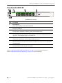
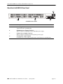


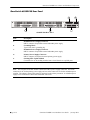

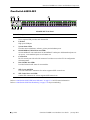
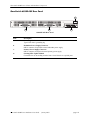

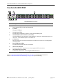
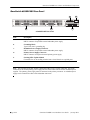

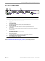
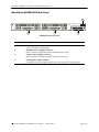

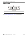


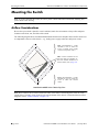
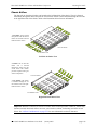

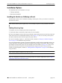
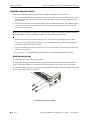
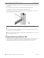
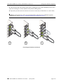
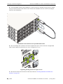


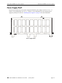
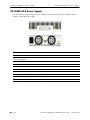
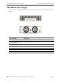
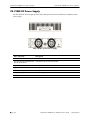
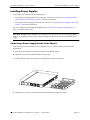
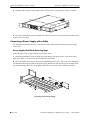
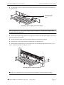
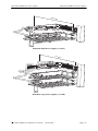
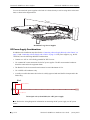
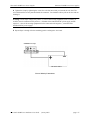


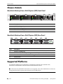

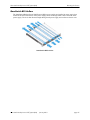
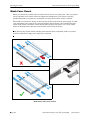
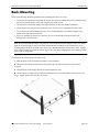
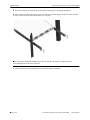
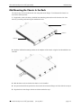
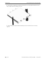
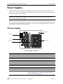

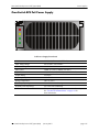


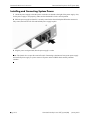
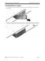
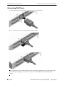

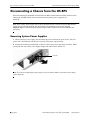
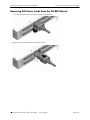
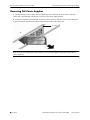


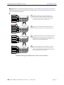
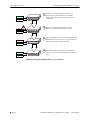
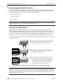
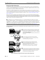
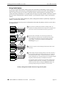
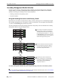
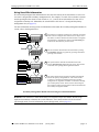
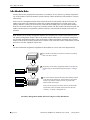


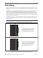
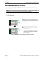
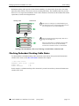

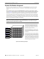
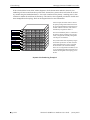
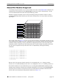
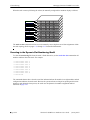
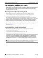


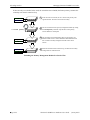
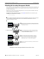
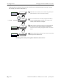


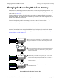
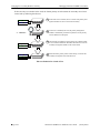


![G2 Decoder [obsolete] Second Generation User Manual](http://vs1.manualzilla.com/store/data/005963661_1-2c18e92993151caf68904a7a924089ff-150x150.png)
![AWD10SS [obsolete] User Manual](http://vs1.manualzilla.com/store/data/005777265_1-bc3e4afb4b891fb2fe3c32a930faa0e5-150x150.png)