1
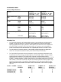
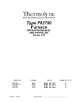
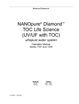
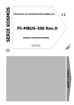
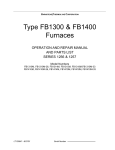
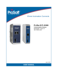
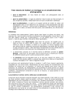
Thermolyne
Barnstead|Thermolyne Corporation
Type 30400
Thermolyne Furnace
OPERATION MANUAL
AND PARTS LIST
Series 718
AUTOMATIC MODELS
MODEL NUMBER
F30420C
F30428C
PHASE
1
1
VOLTAGE
240
208
DISPLAY
°C & °F
°C & °F
PROGRAMMABLE MODELS
MODEL NUMBER
F30430CM
F30438CM
F30420C-70
F30428C-70
PHASE
1
1
1
1
VOLTAGE
240
208
240
208
DISPLAY
°C & °F
°C & °F
°C & °F
°C & °F
PROGRAMMABLE ASHING MODELS
MODEL NUMBER
F30430CM-60
F30438CM-60
F30420C-60-70
F30428C-60-70
LT718X1 • 12/4/00
PHASE
1
1
1
1
VOLTAGE
240
208
240
208
DISPLAY
°C & °F
°C & °F
°C & °F
°C & °F
Serial Number: _______________________________
Read All Warnings, Cautions and Instructions Carefully Before Operating This Thermolyne Furnace.
IMPORTANT INFORMATION
This manual contains important operating and safety information. You must carefully
read and understand the contents of this manual prior to the use of this equipment.
Table of Contents
Safety Information.........................................................................................................................3
Alert Boxes ..................................................................................................................................3
Warnings......................................................................................................................................3
Introduction..................................................................................................................................4
General Specifications ..............................................................................................................4
Intended Use ...........................................................................................................................4
Principles of Operation..............................................................................................................5
Unpacking....................................................................................................................................9
Installation....................................................................................................................................9
Single Setpoint Temperature Control (Automatic) Operation (Models F30420C and F30428C) .......10
Controls and Displays..............................................................................................................10
Adjusting Furnace Setpoint Temperature.................................................................................11
Tuning...................................................................................................................................11
Changing Temperature Indication............................................................................................12
Setting the High Alarm Temperature (Over Temperature Protection OTP) ..................................12
Alarm Indications.....................................................................................................................12
Operation of 2 Ramp & 2 Dwell Programmable Models (F30420C-70, F30428C-70, F30420C-60-70,
F30428C-60-70) ........................................................................................................................13
Controls and Displays..............................................................................................................13
Parameters.............................................................................................................................14
Tuning Your Controller............................................................................................................15
Operating the Controller..........................................................................................................16
Single Set Point Operation..............................................................................................16
Programming Controller ..................................................................................................16
Implementing Programs ..........................................................................................................17
8 Ramp & 8 Dwell Multi-Programmable Models (Models F30430CM, F30438CM, F30430CM-60,
F30438CM-60)...........................................................................................................................19
Controls and Displays..............................................................................................................19
Parameters.............................................................................................................................20
Tuning Your Controller............................................................................................................21
Operating the Controller..........................................................................................................22
Single Set Point Operation..............................................................................................22
Programming Controller ..................................................................................................22
Implementing Programs ..........................................................................................................24
Program Execution.........................................................................................................24
Parameter Change While Running...................................................................................24
Loop Count....................................................................................................................24
Program Hold .................................................................................................................24
Program Reset ...............................................................................................................24
Installation and Operation of Air Control........................................................................................25
Furnace Loading ........................................................................................................................26
Preventative Maintenance...........................................................................................................26
Problem Solving.........................................................................................................................27
Maintenance and Servicing .........................................................................................................28
To Replace a Heating Element.................................................................................................29
2
To Replace a Platinel II Thermocouple......................................................................................29
To Replace Solid State Relay...................................................................................................30
To Replace Door Switch (Microswitch)......................................................................................30
To Realign Door Switch (Microswitch).......................................................................................30
To Replace Control Module.....................................................................................................31
Replacement Parts List ...............................................................................................................32
Ordering Procedures..................................................................................................................32
Material Safety Data Sheet...........................................................................................................36
Warranty.....................................................................................................................................38
Safety Information
Your Thermolyne furnace has been designed with function, reliability and safety in mind. It is your
responsibility to install it in conformance with local electrical codes. For safe operation, please pay
attention to the alert boxes throughout the manual.
Alert Boxes
WARNING
Warning alerts apply when there is a possibility of personal injury.
CAUTION
Caution alerts apply when there is a possibility of damage to the equipment.
NOTE
Notes alert the manual user to pertinent facts and conditions.
Warnings
WARNING
To avoid electrical shock, this furnace must:
1. Use a properly grounded electrical outlet of correct voltage and current handling capacity.
2. Disconnect from the power supply prior to maintenance and servicing.
3. Have the door switch operating properly.
To avoid burns, this furnace must:
1. Not be touched on the exterior or interior surfaces during use or for a period of time after use.
To avoid personal injury:
1. Do not use in the presence of flammable or combustible materials; fire or explosion may result.
This device contains components which may ignite such material.
2. Refer servicing to qualified personnel.
3. This furnace contains refractory ceramic insulation which can produce respirable fibers and dust
when handled. These fibers can cause irritation and can aggravate pre-existing respiratory
disease. The International Agency for Research on Cancer (IARC) has classified refractory
ceramic fiber as possibly carcinogenic. After service refractory ceramic fiber dust may contain
crystalline silica, which may cause lung damage (silicosis) and which has been classed by IARC as
a probable carcinogen.
3
Barnstead |Thermolyne • 800-553-0039
Introduction
General Specifications
Models
F30420C
F30420C-70 & (-60)
F30430CM & (-60)
F30428C
F30428C-70 & (-60)
F30438CM & (-60)
Overall Dimensions IN. Width
(CM)
Height
Depth
Chamber Dimensions Width
IN. (CM
Height
Depth
Weight
Lbs. (KG)
Electrical Ratings
Volts
Amps
Watts
Freq.
Phase
Temperature Ratings Cont.
°F (°C)
21 1/2 (55)
29 1/2 (75)
25 1/2 (65)
14 (35)
14 (35)
14 5/8 (37)
188 (86)
240
22.9
5500
50/60
1
400°F-1800°F*
(204°C)-(982°C)
21 1/2 (55)
29 1/2 (75)
25 1/2 (65)
14 (35)
14 (35)
14 5/8 (37)
188 (86)
208
23.4
5500
50/60
1
400°F-1800°F*
(204°C)-(982°C)
Intermittent
1800°F-2000°F
1800°F-2000°F
(982°C)-(1093°C)
(982°C)-(1093°C)
* The maximum continuous temperature for ashing furnaces (-60 models) is 1787°F (975°C).
Intended Use
1.
The Type 30400 Automatic and Programmable furnaces are general laboratory and heat treating
furnaces. For optimum element life, Thermolyne recommends these furnaces for applications
requiring temperatures from 400°F (204°C) to 1800°F (982°C) for continuous use, or temperatures
from 1800°F (982°C) to 2000°F (1093°C) for intermittent use. Continuous use is operating the
furnace for more than 3 hours and intermittent use is operating the furnace for less than 3 hours.
2.
The unit consists of 1) a heating chamber; 2) an automatic proportioning digital set, digital read
control with overtemperature protection and 3) a door interlock relay for user safety.
3.
The Type 30400 Programmable furnace is designed to control a programmed temperature profile.
The profile is in the format of ramps and dwell segments. The first ramp, RAMP 1, starts at the initial
measured furnace temperature. This ramp is positive going at a programmed rate until the
programmed level is reached. The setpoint will stay at this level for a period determined by the setting
of DWELL 1. Additional positive or negative going ramps are now initiated starting at the level at the
end of DWELL 1. When the second ramp reaches the second programmed level, the setpoint stays
at that level for the duration of the segment. Depending upon the model ordered, additional ramp
and dwell segments may be added. See specific model number below for total number of program
segments.
MODEL NUMBER
F30420C-70 & (-60)
F30428C-70 & (-60)
F30430CM & (-60)
F30438CM & (-60)
DIGITAL
COMMUM.
NO
NO
YES
YES
NUMBER OF
RAMP
SEGMENTS
2
2
8
8
4
NUMBER OF
DWELL
SEGMENTS
2
2
8
8
NUMBER OF
STORED
PROGRAMS
1
1
4
4
Typical Profile For Programmable Models Above. Other Profiles May Be Formed.
4.
The Type 30400 Automatic furnace is designed as a single set point controller which reaches and
maintains one temperature value.
Principles of Operation
1.
Furnace: The furnace chamber is heated by four electric resistance heaters which are embedded in a
refractory material. The chamber is insulated with a ceramic fiber insulation. The temperature is
controlled by an automatic proportioning controller using a platinel thermocouple to feed back
information. The control is located under the furnace chamber and is well insulated from the heat
generated in the furnace chamber. The door hinges may be attached for either left or right hand
opening.
2.
Temperature Controller - "Automatic": This furnace controller consists of a microprocessor based
three mode temperature controller having adjustable over-temperature protection and appropriate
output switching devices to control the furnace. This controller is capable of one temperature setting.
3.
Temperature Controller - "Programmable": This furnace controller consists of a microprocessor based
three mode temperature controller/programmer with adjustable overtemperature protection and
appropriate output switching devices to control the furnace. These controllers are capable of multiple
temperature settings by setting ramp and dwell segments.
NOTE
When in the program RUN mode, the programmable controller serves to provide a
programmed temperature profile as described earlier. When in the single setpoint
automatic mode, the unit serves as an automatic temperature controller.
5
Barnstead |Thermolyne • 800-553-0039
Multi-Programmable Control (8 Ramp and 8 Dwell X 4 Programs)
2 Ramp and 2 Dwell Programmable Control
6
Single Setpoint Controller
7
Barnstead |Thermolyne • 800-553-0039
8
Unpacking
1.
Visually check for any physical damage to the shipping container. Inspect the equipment surfaces
that are adjacent to any damaged area. Open the furnace door and remove packing material from
inside the furnace chamber. Vacuum the chamber prior to use to remove the insulation dust due to
shipment. Two shelves are supplied with furnace.
2.
Retain the original packaging material if re-shipment is foreseen or required.
NOTE
The Type 30400 furnaces do not come with a power cord because current requirements
are too great to be handled by ordinary power cords and standard wall supply.
Installation
Site Selection:
Install furnace on a sturdy surface and allow space for ventilation.
CAUTION
Be sure ambient temperature does not exceed 104°F (40°C). Ambients above this level
may result in damage to the controller.
Allow at least six inches of space between the furnace and any vertical surface. This
permits the heat from furnace case to escape so as not to create a possible fire hazard.
The electrical specifications are located on the specification plate on the back of the furnace. Consult
Barnstead/Thermolyne if your electrical service is different than those listed on the specification plate.
Prior to connecting your Type 30400 furnace to your electrical supply, be sure the front power switch and
rear circuit breaker are in the OFF position.
WARNING
To avoid electrical shock, this furnace must be installed by a competent, qualified
electrician who insures compatibility among furnace specification, power source and
ground code requirements.
Your 30400 furnace may be wired either directly through a conduit system or by using a power cord and
plug which conforms to the National Electrical Codes and electrical code requirements of your area. The
terminal block to be used in wiring is located on the lower rear of the furnace. (See Fig. 3C).
CAUTION
For supply connections, use 10 AWG or larger wires suitable for at least 90°C. Failure to
observe this caution could result in damage to furnace.
9
Barnstead |Thermolyne • 800-553-0039
Observe These Warnings Before Operating Your Furnace:
WARNING
Do not use in the presence of flammable or combustible chemicals; fire or explosion may
result. This device contains components which may ignite such materials.
WARNING
To avoid burns, this furnace must not be touched on the exterior or interior furnace
surfaces during use or for a period of time after use.
Single Setpoint Temperature Control (Automatic)
Operation (Models F30420C and F30428C)
NOTE
The temperature control in these models is a single set-point device. By using the "UP" or
"DOWN" buttons a specific temperature can be chosen. The control will cause the furnace
chamber to heat to the chosen temperature and hold it at this temperature until you turn off
the power switch or select another temperature.
Controls and Displays
Power Switch:
Switch power switch to the "ON" position. The CONTROLLER will illuminate when power is on.
Cycle Indicator:
The amber cycle light will illuminate whenever the door is closed and the actual chamber temperature is
less than the setpoint temperature. This light will go out when the door is open, when the chamber
temperature has reached the setpoint temperature or when there is an over-temperature condition.
Door Safety Switch:
The door safety switch removes power from the heating elements when the door is opened. Open and
close the door a few times, note that the amber cycle light will go out while the door is open. If the cycle
light does not go out while the door is open, consult the Problem Solving section before proceeding.
WARNING
To avoid electrical shock, this furnace must have the door switch connected and operating
properly. If the furnace power light does not go out while the door is open, consult the
Problem Solving section before proceeding.
Control Buttons
To illuminate the "DOWN" button, "SCROLL" button, and "UP" button, touch anywhere on the front
panel.
10
NOTE
When performing the operations with the controller, remember that if more than eight to ten
seconds elapse before the buttons are used again, the display screen will automatically
switch back to displaying chamber temperature. If this happens, light up the front panel again
and step through each parameter until you reach the point at which the interruption occurred.
The parameter values you adjusted earlier, however, will not be lost or altered. Holding down
on the "SCROLL" button allows longer viewing time.
Digital Readout:
The Digital Readout continuously displays chamber (upper display) and setpoint (lower display)
temperatures unless the "SCROLL" button is depressed.
Startup Display:
When the power switch is turned on, the controller will perform a self-test to make sure controller is
operating properly. (If all four 1's do not light up or fails to go to "8888" contact Thermolyne.)
Adjusting Furnace Setpoint Temperature:
To illuminate the "DOWN" button, "SCROLL" button, and "UP" button, touch anywhere on the front
panel.
Push the "UP" button or the "DOWN" button to modify the temperature setpoint (lower digital display).
CAUTION
Do not exceed limitations for continuous or intermittent operating temperature shown in
the General Specifications. Exceeding these limits will result in severely reduced heating
element life.
Tuning:
This control incorporates a self tuning feature which determines the optimum control parameters for the
best temperature accuracy. We recommend that you tune the furnace to your specific application to obtain
the best results. Perform the following procedures when you first set up your furnace and each time you
change your load type or operating temperature.
To tune your furnace:
Load your furnace with a load characteristic of those you intend to heat in it.
Set the furnace's setpoint to the temperature you intend to use for your application.
Push the "SCROLL" button until 'tunE" appears. To start the tuning function, push the "UP" button.
When the tuning process is started, the lower display will flash 'tunE" along with the furnace temperature
setpoint. During tuning, the temperature setpoint cannot be changed. To change temperature setpoint
'tunE" must be turned "OFF." (To stop the tuning function, push the "DOWN" button.)
11
Barnstead |Thermolyne • 800-553-0039
NOTE
If the power to furnace is "turned off" or interrupted while in "tuning,"upon returning power to
furnace, the controller display will indicate "LinE FAIL" because sampled data could be
questionable. To restart tuning, refer to "Tuning" procedure.
If the controller cannot maintain temperature setpoint, "tunE FAIL" will appear on display.
First, correct problem responsible for not maintaining the temperature setpoint, then restart
the "tuning" procedure.
Changing Temperature Indication:
Push "SCROLL" button once, "°C" will appear. This indicates temperature measurement. (Contact
Thermolyne if control needs to be changed to °F.)
Setting the High Alarm Temperature (Over Temperature Protection OTP):
Push "SCROLL" button until "AL.SP" (Alarm Setpoint) appears. The lower display should indicate
1100°C.
NOTE
HIAL- HIGH ALARM. (over-temperature protection, OTP)
The controller is fitted with a mechanical relay which is de-energized in the alarm mode. This
relay, when de-energized, removes power from the heating elements. If the primary control
circuit fails, the OTP will control the furnace temperature at the preset value you have
entered. It does not shut off the furnace. but will maintain the chamber temperature at that
value.
Depress either the "UP" or "DOWN" button to select the OTP value you desire. Thermolyne recommends
that you set the value either at the maximum operating temperature of the furnace or a value of 20
degrees above your working temperature if you desire to provide protection for your workload.
Alarm Indications:
Over-temperature
In the event that the furnace chamber temperature exceeds the value of "AL.SP", the red "AL" lamp will
light and the alarm relay will be de-energized, cutting off power to the heating elements. When the
chamber temperature falls below the value of "AL.SP", the red "AL" lamp will extinguish and the alarm
relay will re-energize, returning power to the heating elements and allowing the chamber to heat again.
This process will repeat continuously until you rectify the problem that caused the over-temperature
situation.
Thermocouple Failure
In the event that the thermocouple circuit breaks or the thermocouple fails, the display will indicate
"SnSr FAIL" and the output power level will be decreased to 0%. When the problem with the
thermocouple circuit has been rectified, the controller will resume controlling with the same output power
level used at the moment of the break or failure.
12
Operation of 2 Ramp & 2 Dwell Programmable
Models (F30420C-70, F30428C-70, F30420C-60-70,
F30428C-60-70)
Controls and Displays
Digital Readout:
The digital readout continuously displays chamber (upper display) and setpoint (lower display)
temperatures unless the PAR (parameter) button is depressed.
If a program is in either run, Hb or Hold, pressing "PAR" once causes the lower display to indicate the
current segment of the program (r1, d1, r2, d2, or Hb) along with °C or °F. If the program is currently in
either d1 and d2, the value shown below these parameters (d1 and d2) reflects the time remaining in the
segment.
While the program is in run, Hold, or Hb, the set point shown on the bottom display is the current working
set point.
When the controller is in idle, depressing PAR shows each parameter and its current value in turn on the
display. The parameter value can either be modified with the "up" or "down" push buttons or left
unmodified.
See Parameters for a list of the controller parameters in order.
NOTE
In the event of a thermocouple break (open circuit), the numeric display increases rapidly
upscale, then displays "Sn b" (sensor break), and may alternatively flash "HiAL" (high alarm)
and/or dAL (deviation alarm) and the sensor break power value.
A reversed thermocouple connection or incorrect thermocouple will cause the display to read
"ur" (underrange) and the control will maintain the sensor break power output value selected.
NOTE
When performing operations with the controller, if you depress and release either the "PAR,"
scroll "up," or scroll "down" push buttons and more than 6 seconds elapse before the
buttons are used again, the display screen will automatically switch to displaying chamber
temperature. If this happens, you will have to step through each parameter until you reach the
point at which the interruption occurred. The parameter values you adjusted earlier, however,
will not be lost or altered. Holding down on "PAR" allows longer viewing time.
Power Switch: Set power switch to the "ON" position. The CONTROLLER will illuminate when power is
on.
CAUTION
Remember that whenever the power switch is turned "ON," the furnace will begin to heat
at the setpoint temperature that was previously set. This value will remain unchanged for
up to a year without power being applied to the control.
13
Barnstead |Thermolyne • 800-553-0039
Cycle Indicator:
The amber cycle light will illuminate whenever the door is closed and the actual chamber temperature is
less than the setpoint temperature. This light will go out when the door is open, when the chamber
temperature has reached the setpoint temperature or when there is an over-temperature condition.
Door Safety Switch:
The door safety switch removes power from the heating elements when the door is opened. Open and
close the door a few times, note that the amber cycle light will go out while the door is open. If the cycle
light does not go out while the door is open, consult the Problem Solving section before proceeding.
WARNING
To avoid electrical shock, this furnace must have the door switch connected and operating
properly. If the furnace power light does not go out while the door is open, consult the
Problem Solving section before proceeding.
NOTE
Pushbutton "A/M" and light "OP2" are inactive and not used.
Parameters
PROG - program options . By pushing up or down buttons, three options can be chosen: run - to
start program; idle - to end program; hold - to hold program until further action.
SP - set point temperature. When running a program, it is the last temperature value attained. Push
up or down button to set.
TUNE - self-tuning feature. Push up or down button to set.
LC - loop count. The number of times the program is repeated. Push up or down button to set.
r1 - ramp rate #1. The rate of heat increase or decrease in °/minute. Push up or down button to set.
L1 - temp level #1. The temp level that r1 will attain. Push up or down button to set.
d1 - dwell (soak) time #1. The amount of time in minutes to hold L1 temp level #1. Push up or down
button to set.
r2 - ramp rate #2. The rate of heat increase or decrease in °C/minute. Push up or down button to set.
L2 - temp level #2. The temperature level r2 will attain. Push up or down button to set.
d2 - dwell (soak) time #2. The amount of time in minutes to hold L2 temperature level #2. Push up or
down button to set.
Hb - "holdback." Automatically places the programmer into "HOLD" if the measured value deviates
more than a specified amount from programmer setpoint. When measured value reenters the holdback
band, the timing for the segment resumes. (Parameter is expressed in °C and only functions when
running a program). Push up or down button to set.
HiAL - high alarm (over temperature protection). Push up or down button to set. Thermolyne
recommends that you set the value either at the maximum operating temperature of the furnace or a value
of 20 degrees above your working temperature if you desire to provide protection for your workload.
NOTE
The controller is fitted with a mechanical relay which is de-energized in the alarm mode. This
relay, when de-energized, removes power from the heating elements. If the primary control
circuit fails, the OTP will control the furnace temperature at the preset value you have
entered. It does not shut off the furnace but will maintain the chamber temperature at that
value.
14
The next three parameters - Proportional Band, Integral and Derivatives - are the three control parameters
of a P.l.D. control system. These parameters will be set when you tune your furnace. (See Tuning.)
Prop - Proportional Band.
In.t - Integral Time.
dEr.t - Derivative Time.
HPl - High Power Limit (%) This parameter limits the average maximum power that is applied to the
heating elements. Remember that this parameter does not reduce the voltage to the elements. It reduces
the average power to the elements by cycling power on and off.
C/F - Centigrade/Fahrenheit. Choose the desired temperature unit by depressing the "UP" or
"DOWN" pushbutton.
NOTE
All temperature dependent parameters are automatically converted when the temperature
unit (C or F) is changed.
Tuning Your Controller
This programmable control has an automatic tuning feature which installs optimum tuning parameters to
give the best temperature accuracy. No manual loading of tuning parameters is needed. We highly
recommend using this feature to provide the best temperature accuracy the controller can attain. Perform
the following procedures when you first set up your furnace and each time you change your load type,
operating temperature, or program.
To initiate the self tune feature:
Load your furnace with a load characteristic of those you intend to heat in it.
If you will be using the controller as a single Setpoint Controller, set the furnace's setpoint to the
temperature you intend to use for your application.
If you will be running a multi-step program, set the furnace's setpoint to the value of L1 (temp level
#1).
Push "PAR" button until TUNE is displayed, then push "UP" or "DOWN" button to turn tune "ON."
During the operation, TUNE flashes in the lower display. Do not make any adjustments to the controller
parameters during this period. The self tuning is finished when TUNE no longer flashes in the lower
display.
Self tuning will calculate values for:
Proportional band - prop
Integral time - Int.t
Derivative time - der.t
• Self tuning cannot be initiated while running a program.
• A power failure will cause the TUNE parameter to revert back to NO. (Reset tune parameter to YES).
• If there are alarm conditions during self tuning, they flash alternately with TUNE.
15
Barnstead |Thermolyne • 800-553-0039
Operating the Controller
CAUTION
Do not exceed limitations for continuous or intermittent operating temperature shown in
the General Specifications (in furnace manual). Exceeding these limits will result in
severely reduced heating element life.
Single Set Point Operation
The programmable control can be used as a single setpoint control or as a programmable control. To use
as a single set point control simply push up or down buttons to choose a specific temperature. The control
will cause the furnace chamber to heat to the chosen temperature and hold this temperature until the
power switch is set to OFF or another temperature is selected.
a.
The setpoint temperature presently set in the control will be read out on the lower display.
b.
To change this set point, depress the "UP" or "DOWN" push button until the desired setpoint value
is displayed then release the button.
c.
At this point the furnace will begin to heat if the new set point temperature you have chosen is higher
than the present chamber temperature.
Programming Controller
To run a program, first determine your ramp rate, dwell times. and program levels. It is helpful to graph your
program out for ease of loading the program into controller.
A maximum of 2 ramp and 2 dwell segment combinations are available, thus enabling 2 different set point
levels to be achieved. Each ramp is programmed by specifying the temperature level (L1) and the required
ramp rate (r1). The controller then automatically calculates the time that is required to attain the
temperature level (L1) based on the desired ramp rate (r1). Dwell segments (d1) then can be attached to
each temperature level (L1) to hold that temperature for a specified amount of time.
Make sure the PROG parameter is set to idle (to stop program) when entering program values. (See
Parameters.)
Push "PAR" until "r1" is displayed. Push "UP" or "DOWN" buttons and set ramp rate "r1" (heat increase or
decrease) in °C/minute.
Push "PAR" until "L1" is displayed. Push "UP" or "DOWN" buttons and set temperature level "L1." This is
the target temperature for the first ramp.
Push "PAR" until "d1" is displayed. Push "UP" or "DOWN" buttons and set dwell (soak) time "d1" in
minutes.
Push "PAR" until "r2" is displayed. Push "UP" or "DOWN" buttons and set ramp rate "r2" in C/minutes.
Push "PAR" until "L2" is displayed. Push "UP" or "DOWN" buttons and set temperature level "L2." This is
the target temperature for the second ramp.
Push 'PAR'' until "d2" is displayed. Push "UP" or "DOWN" buttons and set dwell (soak) time "d2" in
minutes.
16
Push "PAR" until "SP" is displayed. Push "UP" or "DOWN" buttons and modify set point temperature.
After "d2" dwell time has expired, thus ending the program, the last temperature level to be attained will be
equal to "SP" temperature. For example, if after your program has been completed, you want the furnace
to cool to ambient, set "SP" to 20. This will be the last temperature level attained.
Push "PAR" until "LC" is displayed. Push "UP" or "DOWN" buttons and set "LC" (loop count - number of
times program is repeated).
Skipping Segments
If you desire to skip a ramp or dwell segment, follow this procedure:
• for a dwell segment, enter a setting of "0" minutes.
• for a ramp segment, enter a high value such as 100°/min. This will cause controller to skip to next
segment as fast as the furnace is capable.
Setting the Holdback Feature
This controller features a holdback (Hb) function to ensure programmed parameter values are adhered to.
Holdback is set in display units (degrees C or F) and represents the allowable excursion of measured value
away from the current set point, either above or below, before the program is forced into hold (clock
stops).
The program will remain in hold until the measured value comes within holdback band (clock starts). This
feature is active the whole time that the program is running. (Holdback functions only while running a
program).
Push PAR until "Hb" is displayed. Select desired holdback setting - a setting of 20° is recommended.
If a running program is forced into holdback, the illuminated dot below the "R" symbol on controller will
flash and the PROG parameter will indicate "Hb." When the program is in "holdback," it effectively
lengthens the time of the program - if the holdback band "Hb" is set too low, the program will never escape
the holdback band, thus the program will never be completed. If you do not want to use the holdback
function, set "Hb" to an extremely large value.
Implementing Programs
When you have finished programming and are ready to run your program, push "PAR" until PROG is
displayed. Pushing the "UP" or "DOWN" buttons, you have three options: "Run" (to start program), "idle"
(to stop program), "hold" (to hold program) - parameter values can be changed when hold is chosen.
Program Execution
When "run" is selected, the program will start from the actual furnace temperature at that point in time.
Also, the dot under "R" on the control will illuminate to indicate the program is running.
NOTE
Notes alert the manual user to pertinent facts and conditions.
Parameter values r1, L1, D1, r2, L2, D2 and LC cannot be adjusted while running a program.
Program Hold
To adjust parameters while running a program, you must put control into "Hold." Push "PAR" until "prog" is
displayed. Push "UP" or "DOWN" buttons until Hold is displayed. When the dot underneath "R" on
17
Barnstead |Thermolyne • 800-553-0039
controller flashes and "Hold" is indicated at the "prog" parameter, the controller is in Hold. Now you are
able to adjust all parameters. To restart the program, set "prog" to "run" again.
Program Idle
To stop program, push "PAR" button until "prog" is displayed. Push "UP" or "DOWN" buttons until "idle" is
displayed. This will terminate program.
18
8 Ramp & 8 Dwell Multi-Programmable Models
(Models F30430CM, F30438CM, F30430CM-60,
F30438CM-60)
Controls and Displays
Digital Readout:
The digital readout continuously displays chamber (upper display) and setpoint (lower display)
temperatures unless the scroll button is depressed.
If the scroll button is depressed and released, the lower display will indicate output power (OP) or setpoint
(SP). This is referred to as the "short scroll." Continued single step action of scroll button will cause lower
display to alternate between setpoint (SP) and output power (OP).
To enter the main scroll list (list of all controller parameters that are accessed through front keyboard), the
scroll button should be held depressed. PR1 (program ramp rate 1) will appear. To progress through the
parameter list, the scroll button must first be released; subsequent single step depression will advance
you through the list. Rapid progression through the parameter list is achieved by holding the scroll button
depressed.
See Parameters for a list of the controller parameters in order.
NOTE
When performing operations with the controller, if you depress and release either the "scroll,"
"up," or "down" push buttons and more than 8 seconds elapse before the buttons are used
again, the display screen will automatically switch back to displaying setpoint temperature. If
this happens, you will have to step through each parameter until you reach the point at which
the interruption occurred. The parameter values you adjusted earlier, however, will not be lost
or altered.
NOTE
To change from °C indication to °F indication, contact Barnstead/Thermolyne.
Power Switch: Turn power switch to the "ON" position.
CAUTION
Remember that whenever the power switch is turned "ON," the furnace will begin to heat
at the setpoint temperature that was previously set in. This value will remain unchanged
for up to a year without power being applied to the control.
Cycle Indicator:
The amber cycle light will illuminate whenever the door is closed and the actual chamber temperature is
less than the setpoint temperature. This light will go out when the door is open, when the chamber
temperature has reached the setpoint temperature or when there is an over-temperature condition.
Door Safety Switch:
The door safety switch removes power from the heating elements when the door is opened. Open and
close the door a few times, note that the amber cycle light will go out while the door is open. If the cycle
light does not go out while the door is open, consult the Problem Solving section before proceeding.
19
Barnstead |Thermolyne • 800-553-0039
WARNING
To avoid electrical shock, this furnace must have the door switch connected and operating
properly. If the furnace power light does not go out while the door is open, consult the
Problem Solving section before proceeding.
NOTE
The two center push buttons are inactive and not used.
Parameters
Pnr - Program Number. The program number of the program you are are going to work with. By
pushing the up or down button you can select a program numbered from 1 to 4.
PR1 - Program Ramp Rate. The rate of heat increase or decrease in °C/minutes. Pushing the up or
down button will give current setting of this ramp.
PL1 - Program Level. The temperature to which the furnace needs to attain. Push up or down button
to set.
PD1 - Program Dwell 1. Amount of time in minutes to hold PL1 program level temperature entered.
Push up or down button to set.
You will use the same descriptions and procedures used for PR1, PL1, PD1 for the remaining Program
Ramp Rates PR2 - PR8, Program Levels PL2 - PL8, and Program Dwells PD2 - PD8.
Cnt - Continue. Allows linking of programs. You may select Cnt as "y" (yes) or "n" (no) by pushing the
up or down button.
HB - Holdback. Automatically places the programmer into "Hold" if the measured value deviates more
than a specified amount from programmer setpoint. When measured value re-enters the holdback band,
the timing for the segment resumes. (Parameter is expressed in °C and only functions when running a
program). Push up or down button to set.
PLC - Program Loop Count. The number of times a program will be repeated. Push up or down
button to set.
SP1 - Setpoint One. Indicates current setpoint. Push up or down button to set.
SP2 - Setpoint two. Not configured into control and nonfunctional. Set to "20".
AT - Adaptive Tune. Analyzes and inputs optimum PID values when temperature has reached
setpoint. This function does not have a value; it is either "ON" or "OFF." (See Furnace Operation for
function of Adaptive Tune).
ATR - Adaptive Tune Range setting. Determines the operational band width of the adaptive tuning
function. Self Tuning automatically determines this setting.
AL1 - Alarm 1. A full scale alarm which protects load and furnace when temperature exceeds preset
value. Furnace will control temperature at the preset temperature value; it will not shut off furnace. Push
up or down button to set.
NOTE
Thermolyne recommends that you set the value either at maximum operating temperature of
the furnace (1100°C = 2012°F) or a value of 20 degrees above your working temperature if
you desire to provide protection for your workload.
20
The next three parameters - Proportional (PB) Integral (+i) and Derivative (+d) - are the three control
parameters of a P.l.D. control system. These parameters will be set when you tune your furnace. (See
Tuning Your Controller.)
Pb - Proportional.
(+i) - Integral.
(+d) - Derivative.
The next two parameters - cutback low (cbl) and cutback high (cbh) - are to aid the control in preventing
temperature overshoots and undershoots. The point from setpoint where the power starts "cutting back"
is defined as the cutback value. These values are also automatically adjusted by the Self Tuning and
Adaptive Tuning features. These values cannot be changed by the user; the controller automatically
installs optimum cutback values when in Self Tuning and Adaptive Tuning.
HL - Output Power limits the average maximum power that is applied to the heating elements. Normal
setting is 100%. If you plan to use the furnace below 260°C (500°F) the output power may be reduced.
This will significantly shorten the time it takes for stabilization. It will also reduce drastic temperature
overshoots. Contact Barnstead/Thermolyne Customer Service for advice on the proper value to use.
Remember that this parameter does not reduce the voltage to the elements. It reduces the average power
to the elements by cycling power on and off.
HC - Cycle Time is the rate at which power is supplied to power control switch. Push up or down button
to set.
Sbr - the percent of power that is supplied to the control output terminals if an open
thermocouple condition exists. Push up or down button to check. 0.0 will be displayed. This
parameter cannot be changed; if 0.0 is not displayed, contact Barnstead/Thermolyne. The upper display
will flash "OR" if an open thermocouple condition exists.
Tuning Your Controller
The programmable control has automatic tuning features which install optimum tuning parameters to give
the best temperature accuracy. No manual loading of tuning parameters is needed. We highly
recommend using these features to provide the best temperature accuracy the controller can attain.
Perform the following procedures when you first set up your furnace and each time you change your load
type, operating temperature, or program.
The following procedure is instruction on how to initiate the SAT Self and Adaptive Tuning feature. This
feature starts the controller in the Self Tune mode then automatically switches over to the Adaptive
Tuning Feature. Self Tuning is a one-time function which permits the user to retune the instrument control
parameters to suit new process conditions. Adaptive tuning takes over when the self tune is completed
and continuously reevaluates the tuned parameters. Adaptive tuning will then automatically install new
values if a better response could have been attained.
To initiate the tuning feature:
Load your furnace with a load characteristic of those you intend to heat in it.
Depress scroll button until SAT is displayed. Depress the up and down buttons simultaneously to start self
tuning. The A-T indicator is then illuminated (upper right hand comer) and the lower display indicates the
setpoint at which the self-tune sequence will occur. The "SP" indicator will flash for 1 minute, during which
time the setpoint may be changed, if it is required to retune at a new setpoint either above or below the
process value indicated on the upper display. (If you will be using the controller as a single Setpoint
Controller, set the furnace's setpoint to the temperature you intend to use for your application. If you will
21
Barnstead |Thermolyne • 800-553-0039
be running a multi-step program, set the furnace's setpoint to the value of PL1 (Program Level #1).)
At the end of the minute, the "SP" indicator will stop flashing, indicating that the setpoint can no longer be
changed. The A-T indicator will start flashing and continue to flash until the self tune has completed. Once
the self tune is completed, adaptive tune takes over and the A-T indicator will remain illuminated.
To stop tuning, function scroll until SAT is displayed and simultaneously push up and down buttons.
Operating the Controller
CAUTION
Do not exceed limitations for continuous or intermittent operating temperature shown in
the General Specifications. Exceeding these limits will result in severely reduced heating
element life.
Single Set Point Operation
This programmable control can be used as a single setpoint control or as a programmable control. To use
as a single set point control, simply push up or down buttons to choose a specific temperature.
Temperature setpoint or output power is indicated on lower display; single depression of scroll button will
alternate between these two parameters. The control will cause the furnace chamber to heat to the
chosen temperature and hold it at this temperature until you turn off the power switch or select another
temperature.
a.
The setpoint temperature presently set in the control will be read out on the lower display.
b.
To change this set point, depress the "UP" or "DOWN" push button until the desired setpoint value
is displayed then release the button.
c.
At this point the furnace will begin to heat if the new set point temperature you have chosen is higher
than the present chamber temperature.
d.
The upper display indicates the actual furnace temperature.
Programming Controller
The multi-programmable controller in these units provides up to 4 separate programs of 8 ramps and 8
dwells each. This controller also allows you to link programs together, which allows you to achieve 64 total
segments (4 programs X 16 segments). These functions are controlled by the controller's first two
programming parameters, "Pnr" and "Cnt."
A maximum of 8 ramp and 8 dwell segment combinations are available per program, thus enabling eight
different setpoint levels to be achieved. Each ramp is programmed by specifying the program level (PL)
and the required ramp rate (PR). The controller then automatically calculates the time that is required to
attain the program level (PL) based on desired ramp rate (PR). Dwell segments (soak) then can be
attached to each program level (PL) to hold that temperature for a specified time.
To run a program, first determine your ramp rate, dwell times, program levels. It is helpful to graph your
program out for ease of loading program into controller.
To select program number
Push scroll button until "Pnr 1" is displayed. Push the up or down button to select a program number from
1 to 4.
22
Program Entry
To Link Programs Together
Push scroll button until "Cnt n" is displayed. Press and release the up and down buttons to switch
between "Cnt y" (continue yes) and "Cnt n" (continue no). The effect of selecting "Cnt y" is to continue
the program to the next program number. For example, if in program #3 you select "Cnt y," when program
#3 is complete, program #4 will run automatically. Setting "Cnt y" in program #4 will initiate the start of
program #1 upon the completion of program #4. Each program will complete the selected number of
loops before continuing (see Loop Count). If you do not want to link programs, set Cnt to "Cnt n"
(continue no).
NOTE
Once the desired parameter has been selected, depressing either the raise or lower button
will cause the parameter to be replaced with the new value. At this point, the "top dot" of the
least significant digit of the secondary display will flash on and off. Any further use of up or
down buttons will change parameter value. In all cases, the value shown on the display is the
current working value of that parameter.
Set Ramp Rates
1. With the programmer not operating, indicated by the bottom right hand side of the display
extinguished, depress scroll button until PR1 is displayed. Push the up or down button to scroll to
the desired value, which is degrees per minute.
Scrolling down below zero will give three other options for the ramp:
NONE-which will force the program to skip to the next segment;
END-which will cause the program to stop or restart if loops remaining is not zero;
STEP-which will cause the program to ramp as quickly as possible to the next temperature level.
All other ramps in the program are set in a similar fashion by selecting 'PR' followed by the relevant ramp
number.
Set Level Temperatures
2. The level to which the first ramp is aiming is entered by scrolling through the main scroll list until "PL1"
is displayed. By pressing either the up or down button the present value of this level is indicated in
display units. Using the up or down button will scroll the present value to the new value required. All
other levels in the program are set in a similar fashion by selecting 'PL' followed by the relevant
number.
Set Dwell Times
3. To set the dwell time for the first level, scroll through the main scroll list until "Pd1" is displayed.
Pressing the up or down button will reveal the current value of time in minutes. Using the up or down
button will scroll the present value to the new value required. Scrolling this value downscale will allow
a setting of "END." A setting of "END" will terminate the program, or force it to restart if loops
remaining are not zero at the beginning of that dwell.
All other dwells in the program can be set in a similar fashion by selecting "PD" followed by the relevant
dwell number.
Set the Number of Times to Repeat the Program
4. Scrolling through the main scroll until the parameter "PLC" is displayed and then depressing the up
or down button will reveal the present setting of the loop count. This is the number of times that the
entered program will be repeated before a continuous setpoint at the last level of the program is
23
Barnstead |Thermolyne • 800-553-0039
achieved. By pushing the up or down button the number of loops can be set at any value from 1 to
999.
Set the Holdback Feature
5. Scroll through the main scroll list until "HB" is displayed. Push the up or down button to reveal the
current value of holdback. The up or down button can now be depressed to scroll to the required
value. Holdback is set in display units and represents the allowable excursion of measured value
away from the current setpoint, either above or below, before the program is forced into hold. The
program will remain in hold until the measured value comes within holdback limits. This feature is
active the whole time that the program is running. When hold is forced onto the program by holdback,
the "HOLD'"legend is not illuminated but either the "RAMP" or "DWELL" legend will flash.
Implementing Programs
Program Execution
Once the program has been entered it can be set running by depressing the ‘RUN/HOLD' push button on
the front.
NOTE
Be sure to select the program number before pressing "Run/Hold."
With the run initiated, the program will commence and the legend on the display will indicate if a ramp or
dwell is being performed. While a program is running the short scroll will contain a third parameter "TIME."
Push scroll button once; time remaining for the current segment, either ramp or dwell will be indicated. If
the loop counter has been set to any value other than one, then the above procedure will be repeated for
each loop.
At the end of the complete program, an "E" will appear on the display.
Parameter Change While Running
The previous parameters can be inspected but not changed while a program is running. If it is necessary to
alter a parameter while a program is running, the program must be placed into the hold condition. To put
program into hold, push run/hold button once. After modification of the parameter, returning the program
to the run state will cause the program to continue with the changed value(s) installed. Push run/hold
button again to restart program.
Loop Count
If the loop count is set to values other than one, then the number of loops remaining in a running program
can be displayed. To determine which loop is being performed depress scroll button until LR' is displayed
and by pushing either the up or down button the remaining number of loops, excluding the one being
executed, is displayed.
Program Hold
A running program can be forced into hold at any stage by depressing the "RUN/HOLD" push button on
the front. When a running program is forced into hold, "HOLD" legend will appear on the display together
with the segment type and will be flashing. Pushing "RUN/HOLD" button again will return the program to a
run situation and extinguish the "HOLD" legend.
Program Reset
A running, held or finished program can be reset by depressing the up and down push buttons together.
24
When the reset has been enabled, the parts of the display associated with programming will be
extinguished and the controller will operate as a single setpoint control.
NOTE
The temperature control in these models is a programmable "and" automatic single setpoint
device. When the program has ended, the controller will maintain the chamber temperature at
a value equal to the last programmed level (PL) until the program is cancelled. It will not
automatically cool to ambient unless last programmed level (PL) is set at ambient. When a
program is cancelled, the controller will maintain the chamber temperature at a value equal to
the main setpoint (SP1 or SP). To cancel a program, depress and release the "UP" and
"DOWN" push buttons simultaneously. Be sure single set point mode is set to 20 or below
degrees as described earlier in this manual.
Installation and Operation of Air Control
Models F30438CM-60, F30430CM-60, F30428C-60-70, F30420C-60-70
NOTE
Ashing furnaces -60 models contain a feature to provide air (or inert gas) flow within the
furnace chamber.
Installation
NOTE
A pressurized air line with a minimum working pressure range of 0 to 40 psi is required.
Compressed air hook-up
1.
At the rear of the furnace is located a 0.250 inch tube fitting.
2.
Using 0.250 inch I.D. rubber tubing, connect a length of tubing from this input fitting to a
corresponding 0.250 inch fitting located on the regulated side of a pressurized air service line.
3.
Prior to making connections at the regulator, insure that the regulator is turned fully closed (0 psi).
4.
Turn flow control valve located at the bottom of the flowmeter (front control panel) fully clockwise
to closed position.
5.
Turn regulator to maximum output pressure of 30 psi. Check for any leaks at connection points of
connecting tubing.
6.
Open flow control valve slowly until ball in flow meter reads between 40 to 45 liters per minute flow
rate.
7.
Open furnace door and check that air is exhausting from the manifold located at the bottom rear of
the chamber.
8.
Turn flow control valve to off (fully clockwise).
NOTE
If furnace is to be used regularly, the airline regulator may be left open to 30 psi.
25
Barnstead |Thermolyne • 800-553-0039
Exhaust tubing hook-up.
NOTE
Appropriate exhaust must be provided to remove smoke and gases produced in an ashing
procedure.
Using accessory tubing available from Barnstead/Thermolyne Corporation (part number
AY408X1A for furnace temperatures less than 975°C, part number AY718X1 for furnace
temperatures of 975°C or greater) or equal quality 2.5" I.D. tubing appropriate for the
temperatures at which you will operate your furnace, connect flexible tubing from vent port at top
of furnace case to an appropriate negative pressure exhaust system. This exhaust system must
be capable of handling smoke and gases produced in an ashing procedure.
NOTE
Failure to connect the exhaust port to an appropriate exhaust system will result in smoke and
gases filling the work area. Without the connection, gases and smoke will escape around the
door seal and at the rear of the furnace.
Furnace Loading
For best results, use only the center two-thirds of the furnace chamber.
CAUTION
Do not overload your furnace chamber. If the load is to be heated uniformly it should not
occupy more than two-thirds of the furnace chamber. Failure to observe this caution could
result in damage to furnace components.
Use Hearth plate to elevate load when placing on bottom heating element. This prevents bottom heating
element from overheating and burning out. (Part Numbers PHX1 &PHX2)
If you are heating a number of small parts, spread them throughout the center of the furnace chamber.
Keep objects away from thermocouple.
Use insulated tongs and mittens when loading and unloading furnace.
Always wear safety glasses.
Preventative Maintenance
This unit is equipped with a venting system on the top of the furnace. This is for the removal of fumes from
the chamber of the unit. Contamination is a major cause of element failure, therefore, remove all fume
forming material before heating. (e.g. clean cutting oil from tool steel).
Housekeeping is vital to your electric furnace - KEEP IT CLEAN. Run your furnace up to 1600°F empty
occasionally to burn off the contamination that may exist on the insulation and elements. Maintain 1600°F
for at least 4 hours to insure complete ashing of foreign materials.
Element life is reduced somewhat by repeated heating and cooling. If the furnace is to be used again
within a few hours, it is best to keep it at the operating temperature or at a reduced level such as 500°F
(260°C).
26
Problem Solving
The Problem Solving section is intended to aid in defining and correcting possible service problems.
When using the chart, select the problem category that resembles the malfunction. Then proceed to the
possible causes category and take necessary corrective action.
Problem
The cycle light does not
illuminate.
Probable Causes
The furnace is not connected to
power supply.
ON and OFF power switch is
defective.
Door switch defective.
Incorrect power source.
Defective circuit breaker.
The furnace does not heat.
No power.
Defective electrical hookup.
Thermocouple has oxidized and
opened the circuit.
Controller malfunction.
Two or more heating elements in
208V or 240V furnaces are
burned out.
Door switch malfunction.
Defective safety relay.
Defective solid state relay (SSR)
Slow heatup.
Low line voltage.
Heavy load in chamber.
Wrong heating element
One or more heating elements
are burned out.
Wired improperly.
Door switch does not cut power
to the furnace chamber.
Door switch is not functioning.
Safety relay malfunction.
Controller overtemperature alarm Alarm output defective.
does not control power to
furnace chamber.
27
Corrective Action
Check furnace connection to
power source.
Replace power switch.
Re-align or replace furnace door
switch.
Check power source.
Replace circuit breaker.
Check power source and fuses
or breakers.
Repair electrical hookup.
Replace thermocouple.
Contact Thermolyne customer
service.
Replace defective elements.
Re-align or replace door safety
switch.
Replace safety repay.
Replace SS relay.
Install line of sufficient size and
proper voltage (Isolate furnace
from other electrical loads).
Lighten load in chamber to allow
heat to circulate.
Install proper element.
Replace burned out elements.
Check wiring diagram for correct
wiring of your furnace.
Re-align or replace door safety
switch.
Replace safety relay.
Replace control module (contact
Thermolyne).
Barnstead |Thermolyne • 800-553-0039
Problem
Control/Programmer locked up,
not allowing any change to
values.
Probable Causes
Program is running.
Corrective Action
To cancel program, press up &
down arrows at the same time.
Repeated element burnout.
Overheating furnace.
Do not exceed the maximum
operating temperature of furnace
or recommended continuous
intermittent use values.
Enclose material in container.
Clean up spills on chamber.
Ventilate chamber by leaving
door cracked slightly open when
heating known harmful reagents.
Clean and/or replace insulation
material.
Check wiring diagram for correct
wiring of your furnace.
Heating harmful materials.
Contamination present from
previous burnout.
Wired improperly.
Inaccurate.
Oxidized or contaminated
thermocouple.
Poor thermocouple connections.
Improper loading.
Poor ventilation of base.
Control out of calibration.
Replace thermocouple.
Tighten connections.
Use proper loading procedures.
Clear area around furnace base.
Contact Thermolyne.
Maintenance and Servicing
WARNING
This furnace contains refractory ceramic insulation which can produce respirable fibers
and dust when handled. These fibers can cause irritation and can aggravate pre-existing
respiratory disease. The International Agency for Research on Cancer (IARC) has
classified refractory ceramic fiber as possibly carcinogenic. After service refractory ceramic
fiber dust may contain crystalline silica, which may cause lung damage (silicosis) and which
has been classed by IARC as a probable carcinogen.
Refer servicing to qualified personnel.
The refractory ceramic materials are located in the door, and in the chamber of the furnace. Tests
performed by the manufacturer indicate that there is no significant risk of exposure to dust or respirable
refractory ceramic fiber resulting from operation of the equipment under normal conditions. However,
there may be a risk of exposure to respirable refractory ceramic dust or fiber when repairing or maintaining
the insulating materials, or when otherwise disturbing the materials in a manner which causes release of
dust or fibers therefrom. Through the use of proper handling procedures you can work safely with these
insulating materials and minimize any exposure. Accordingly, before you repair or replace any insulating
materials, or perform any other servicing on this product which could disturb or cause exposure to dust
from insulating materials, you should consult the appropriate Material Safety Data Sheets (MSDS’s) for
such products with respect to proper handling and appropriate protective equipment. For additional
28
MSDS’s, or additional information concerning the handling of refractory ceramic products, please contact
the Customer Service Department of Barnstead/Thermolyne Corporation.
WARNING
To avoid electrical shock, this furnace must always be disconnected from the power supply
prior to maintenance and service.
Perform only maintenance described in this manual. Contact an authorized dealer or our
factory for parts and assistance.
To Replace a Heating Element:
a.
Disconnect furnace from power supply.
b.
Remove the back terminal cover of the furnace (Note placement and connections of wires).
c.
Loosen the screws and nuts on the terminals of the element to be replaced. Be careful not to nick
element lead wires.
d.
Open the door and pull the defective element out.
e.
Slide the new element into place, threading the leads through the insulating porcelain bushing on
the back of the furnace.
f.
Cut off any excess lead wire. Be careful not to nick element lead wires. Reinstall terminal connections
and tighten screws and nuts securely.
g.
Replace the back terminal cover.
h.
Reconnect furnace to power supply.
i.
Test operation of furnace.
To Replace a Platinel II Thermocouple:
a.
Disconnect furnace from power supply.
b.
Remove the back terminal cover of the furnace. (Note placement and connection of T/C lead wires).
c.
Remove the screws on the thermocouple terminals and pull the thermocouple straight out.
d.
Insert the new thermocouple into the furnace with blue and yellow beaded lead connected to the
positive (+) marked terminal and other lead to negative (-) terminal.
e.
Secure connections with screws removed in c.
f.
Replace the back terminal cover.
g.
Reconnect the furnace to power supply.
h.
Test operation of furnace.
29
Barnstead |Thermolyne • 800-553-0039
To Replace Solid State Relay:
a.
b.
Disconnect furnace from power supply.
Remove the screws on the front dial and the screws on the lower back cover.
c.
Remove the upper back cover.
d.
Disconnect the element lead wires and one ground wire from back of furnace. Also, disconnect T/C
lead wire from terminal block. (Note placement and connection of of wires).
e.
Slide control section forward and disconnect two wires from door switch. (Note placement and
connection of wires).
f.
Control section can now be removed from furnace housing.
g.
Relay is mounted on heat sink on back of control section. Disconnect wires from relay and remove
relay. (Note placement and connection of wires).
h.
Install new relay.
i.
Reverse steps a - e to reassemble furnace.
j.
Test operation of furnace.
To Replace Door Switch (Microswitch):
a.
Disconnect furnace from power supply.
b.
Remove the four top screws on the front dial and the four bottom screws on the back cover.
c.
Slide the control section forward. (Note: do not pull excessively on the internal wires).
d.
Disconnect the wires from the door switch. (Note connection and placement of wires to Microswitch).
e.
Remove the two screws and nuts from the Microswitch.
f.
Insert new Microswitch and secure with screws and nuts removed in Step e.
g.
Reconnect wires identified or marked in Step c to new door switch.
h.
To realign door switch see To Realign Door Switch (Microswitch) steps e through g.
i.
Slide control section back and replace the screws described in Step b.
j.
Reconnect to power supply.
k.
Test operation of door switch. (To Realign Door Switch (Microswitch) Step f).
To Realign Door Switch (Microswitch):
a.
Disconnect furnace form power supply.
b.
Remove the four top screws on the front dial and the four bottom screws on the back cover.
c.
Slide the control section forward. (Note: do not pull excessively on the internal wires).
30
d.
With the door closed loosen the screws on the microswitch and slide the switch downward, so that
the screws are at the bottom of the slots in the mounting bracket.
e.
Finger tighten both screws. While holding down the rear of the Microswitch housing, gently push up
on the front switch until you hear a click.
f.
Open and close the door; the switch should click when the door is opened approximately 1" and 1/2"
to 1" before the door is closed. Slide the front of the switch up to increase the distance, down to
decrease the distance.
g.
Tighten the two screws to secure the Microswitch. Check the operation of the switch as described in
Step f after tightening the screws.
h.
Slide control section back and replace the screws described in Step b.
i.
Reconnect to power supply.
j.
To test the operation of the door switch: turn the power switch on, set the control to a setting high
enough to keep the control from cycling, open and close the door; the cycle light should turn off
when the door is opened approximately 1" and on 1/2" to 1" before the door is closed.
To Replace Control Module:
a.
Turn the screw on the control counterclockwise. (Located behind the door on 8 ramp and 8 dwell
models.)
b.
As the control module starts to disengage, pull it straight out of the control sleeve.
c.
For single set point models, squeeze top and bottom of control and pull straight out.
31
Barnstead |Thermolyne • 800-553-0039
Replacement Parts List
Series 718
Part Number
CN71X55
CN71X40
Description
Control unit, automatic model
Control Unit, Prog. (2 ramp & 2
dwell)
CN71X56
Control unit, programmable
model (8 ramp & 8 dwell)
Models Used On
F30420C,F30428C
F30420C-70, F30428C-70,
F30420C-60-70, F30428C-6070
F30430CM, F30438CM,
F30430CM-60, F30438CM-60
DR718X1C
Door Assembly
(all models)
EL412X1
EL412X2
EL412X3
Heating element, top,
Heating element, bottom,
Heating element, side,
208 volt models
208 volt models
208 volt models (2 req'd)
EL412X4
EL412X5
EL412X6
Heating element, top,
Heating element, bottom,
Heating element, side,
240 volt models
240 volt models
240 volt models (2 req’d)
PLX82
Cycle light
(all models)
RYX31
RYX37
Mechanical Relay
Solid state relay
(all models)
SWX68
SWX103
SW412X1A
Switch, power on/off
Switch, circuit breaker
Switch assembly, door interlock
(all models)
(all models)
(all models)
TC412X1A
Thermocouple, Type F
(Platinel II)
(all models)
Ordering Procedures
Please refer to the Specification Plate for the complete model number, serial number, and series number
when requesting service, replacement parts or in any correspondence concerning this unit.
All parts listed herein may be ordered from the Barnstead|Thermolyne dealer from whom you
purchased this unit or can be obtained promptly from the factory. When service or replacement parts are
needed we ask that you check first with your dealer. If the dealer cannot handle your request, then contact
our Customer Service Department at 319-556-2241 or 800-553-0039.
Prior to returning any materials to Barnstead |Thermolyne Corp., please contact our Customer
Service Department for a “Return Goods Authorization” number (RGA). Material returned without a RGA
number will be refused.
32
Wiring Diagrams Series 718
Models F30430CM, F30438CM, F30430CM-60 & F30438CM-60
33
Barnstead |Thermolyne • 800-553-0039
Models
Wiring Diagrams Series 718
F30420C-70, F30428C-70, F30420C-60-70,
34
F30428C-60-70
Wiring Diagrams Series 718
Models F30420C & F30428C
35
Barnstead |Thermolyne • 800-553-0039
Thermal
Ceramics
Material Safety
Data Sheet
Date Revised:
7/2/91
PRODUCT IDENTIFICATION
Trade Name(s):
Generic Name:
Chemical Name:
Manufacturer:
Address:
City:
CERAFIBER
REFRACTORY CERAMIC FIBER INSULATION
ALUMINA SILICA
Thermal Ceramics
P.0. BOX 923, 2102 Old Savannah Road
Augusta
State:
Georgia
Zip: 30903
CAS #:
Formula:
Telephone:
65997-17-3
MIXTURE
(404) 796-4200
PRODUCT INGREDIENTS
INGREDIENT NAME
REFRACTORY CERAMIC FIBER
CAS NUMBER
65997-17-3
%
100
CRYSTALLINE SILICA (CRISTOBALITE) WILL FORM
"AFTER SERVICE" AT TEMPERATURES >1000°C.
14464-46-1
>20
PEL and TLV (except as noted)
1 FIBER/CC EXPOSURE GUIDELINE
5mg/M3 - NUISANCE RESPIRABLE - OSHA
10mg/M3 - NUISANCE TOTAL - ACGIH
0.05 mg/M3 - OSHA Respirable Dust
PHYSICAL DATA
Appearance and Odor:
Boiling Point:
Vapor Pressure:
Water Solubility (%):
Vapor Density (Air= l):
WHITE FIBER-NO ODOR.
NA
NA
NIL
NA
Evaporation Rate (NA = 1):
Specific Gravity (water = 1 ):
Melting Point:
% Volatile by Volume:
NA
2.6
>3000°F
0
FIRE AND EXPLOSION DATA
Flash Point (Method):
NONFLAMMABLE
NFPA Flammable/Combustible Liquid Classification:
Flammable Limits:
NA
LEL: NA %
UEL:
NA %
Auto-Ignition Temperature:
HEALTH HAZARDS
Summary/Risks
Summary: EXPOSURE TO DUST FROM THIS PRODUCT SHOULD BE MINIMIZED. ANIMAL INHALATION AND ARTIFICIAL
IMPLANTATION STUDIES HAVE REPORTED THE DEVELOPMENT OF TUMORS. BASED ON PRELIMINARY RESULTS, A
NOTICE OF SUBSTANTIAL RISK HAS BEEN FILED WITH THE EPA ACCORDING TO SECTION 8(e) OF THE TOXIC
SUBSTANCES CONTROL ACT. BASED ON ANIMAL STUDIES, IARC HAS CLASSIFIED RCF AS POSSIBLY CARCINOGENIC
FOR HUMANS (2B). DATA FROM HUMAN EPIDEMIOLOGICAL STUDIES IS INSUFFICIENT. THIS SUBSTANCE OR
MIXTURE HAS NOT BEEN CLASSIFIED A CARCINOGEN BY NTP OR OSHA.
Medical conditions which may be aggravated: AS WITH ANY DUST, PRE-EXISTING UPPER RESPIRATORY AND LUNG
DISEASES MAY BE AGGRAVATED.
Target Organ(s): LUNGS, SKIN AND EYES .
Acute Health Effects: PRODUCT IS A MECHANICAL IRRITANT TO SKIN, EYES AND UPPER RESPIRATORY SYSTEM.
Chronic Health Effects: EXCESSIVE EXPOSURE TO RCF DUSTS AND AFTER SERVICE FIBERS MAY CAUSE LUNG DAMAGE
(FIBROSIS). IARC STATES THERE IS SUFFICIENT EVIDENCE IN ANIMALS AND LIMITED EVIDENCE IN HUMANS TO
CLASSIFY CRYSTALLINE SILICA AS A PROBABLE CARCINOGEN (2A) AND RCF AS A POSSIBLE CARCINOGEN (2B).
Primary Entry Route(s): INHALATION, SKIN AND EYE CONTACT.
Signs/Symptoms of Overexposure
Inhalation: IRRITATION OR SORENESS IN THROAT & NOSE. IN EXTREME EXPOSURES SOME CONGESTION MAY OCCUR.
Skin Contact: TEMPORARY IRRITATION OR RASH.
Skin Absorption: NA
Ingestion: NOT HAZARDOUS WHEN INGESTED. MAY CAUSE TEMPORARY IRRITATION TO GI TRACT.
Eyes: TEMPORARY IRRITATION OR INFLAMMATION
36
NA
First Aid/Emergency Procedures
Inhalation: REMOVE TO FRESH AIR. DRINK WATER TO CLEAR THROAT AND BLOW NOSE TO EVACUATE FIBERS.
Skin Contact: WASH AFFECTED AREAS GENTLY WITH SOAP AND WARM WATER.
Skin Absorption: NA
Ingestion: NA
Eyes: FLUSH EYES WITH COPIOUS QUANTITIES OF WATER. IF IRRITATION PERSISTS CONSULT A PHYSICIAN.
REACTIVITY DATA
MATERIAL IS STABLE.
HAZARDOUS POLYMERIZATION CANNOT OCCUR.
Chemical Incompatibilities: HYDROFLUORIC ACID
Conditions to Avoid: NONE IN DESIGNED USE.
Hazardous Decomposition Products: NONE
SPILL OR LEAK PROCEDURES
Procedures for Spill/Leak: VACUUM CLEAN DUST WITH EQUIPMENT FITTED WITH HEPA FILTER. IF SWEEPING IS
NECESSARY USE A DUST SUPPRESSANT.
Waste Management: WASTES ARE NOT HAZARDOUS AS DEFINED BY RCRA (40 CFR PART 261 ) . COMPLY WITH FEDERAL,
STATE & LOCAL REGULATIONS. METHOD OF DISPOSAL - LANDFILL. RQ - N/A.
SPECIAL PROTECTION INFORMATION
Goggles: GOGGLES OR SAFETY GLASSES WITH SIDE SHIELDS ARE RECOMMENDED.
Gloves: GLOVES ARE RECOMMENDED.
Respirator: <1 F/CC, USE 3M 9900; <10 F/CC, USE MSA COMFO II WITH H FILTER; <50 F/CC, USE MSA ULTRA-TWIN H FILTER;
OR EQUIVALENTS. SEE SECTION IX-OTHER.
Ventilation: USE SUFFICIENT NATURAL OR MECHANICAL VENTILATION TO KEEP DUST LEVEL TO BELOW PEL/TLV/WEG
(WORKPLACE EXPOSURE GUIDELINE) USE DUST COLLECTION WHEN TEARING OUT.
Other: WEAR LOOSE FITTING, LONG SLEEVED CLOTHING. WASH EXPOSED AREAS WITH SOAP & WARM WATER AFTER
HANDLING. WASH WORK CLOTHES SEPARATELY FROM OTHER CLOTHING; RINSE WASHER THOROUGHLY.
Special Considerations for repair/maintenance of contaminated equipment: CRISTOBALITE RESPIRATOR: <10X PEL, USE 3M
9900; <100X PEL, USE MSA ULTRA-TWIN H FILTER; OR EQUIV. SEE SEC IX-OTHER.
SPECIAL PRECAUTIONS
*** ALWAYS SEGREGATE MATERIALS BY MAJOR HAZARD CLASS ***
THIS PRODUCT CONTAINS A CHEMICAL KNOWN TO THE STATE OF CALIFORNIA TO CAUSE CANCER.
Storage Segregation Hazard Classes: IRRITANT
Special Handling/Storage: KEEP MATERIAL DRY.
Special Workplace Engineering Controls: ADEQUATE VENTILATION TO KEEP DUST LEVEL TO BELOW PEL/TLV/WEG
(WORKPLACE EXPOSURE GUIDELINE).
Other: ADDITIONAL INFORMATION ON THE HEALTH AND SAFETY ASPECTS OF REFRACTORY CERAMIC FIBERS IS
AVAILABLE.
† Copyright© 1980, National Fire Protection Assoc., Quincy, MA 02269. This reprinted material is not the complete and official position of
the NFPA on the referenced subject, which is represented only by the standard in its entirety.
MSSM/226-21:26/00030
As of the date of preparation of this document, the foregoing information is believed to be accurate and is provided in good faith to comply
with applicable federal and state law(s). However, no warranty or representation with respect to such information is intended or given.
MSDS/MSD3 FORM REV. 7/2/91
37
Barnstead |Thermolyne • 800-553-0039
Barnstead|Thermolyne
One Year Limited Warranty
Barnstead|Thermolyne Corporation warrants that if a product manufactured by
Barnstead|Thermolyne and sold within the continental United States or Canada proves to be
defective in material or construction, Barnstead|Thermolyne will provide you, without charge, for a
period of ninety (90) days, the labor, and a period of one (1) year, the parts, necessary to remedy any
such defect. Outside the continental United States and Canada, the warranty provides, for one (1) year,
the parts necessary to remedy any such defect. The warranty period shall commence either six (6)
months following the date the product is sold by Barnstead|Thermolyne or on the date it is
purchased by the original retail consumer, whichever date occurs first.
All warranty inspections and repairs must be performed by and parts obtained from an authorized
Barnstead|Thermolyne dealer or Barnstead|Thermolyne. Heating elements, however, because
of their susceptibility to overheating and contamination, must be returned to our factory, and if, upon
inspection, it is concluded that failure is not due to excessive high temperature or contamination,
warranty replacement will be provided by Barnstead|Thermolyne. The name of the authorized
Barnstead|Thermolyne dealer nearest you may be obtained by calling 1-800-446-6060 or writing to:
Barnstead|Thermolyne
P.O. Box 797
2555 Kerper Boulevard
Dubuque, IA 52004-0797
USA
FAX: (319) 556-0695
Barnstead|Thermolyne's sole obligation with respect to its product shall be to repair or replace the
product. Under no circumstances shall it be liable for incidental or consequential damage.
THE WARRANTY STATED HEREIN IS THE SOLE WARRANTY APPLICABLE TO
BARNSTEAD|THERMOLYNE PRODUCTS. BARNSTEAD|THERMOLYNE EXPRESSLY
DISCLAIMS ANY AND ALL OTHER WARRANTIES, EXPRESSED OR IMPLIED, INCLUDING
WARRANTIES OF MERCHANTABILITY OR FITNESS FOR USE.
38
39
Barnstead |Thermolyne • 800-553-0039
40