1
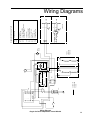
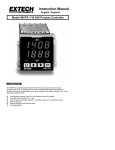
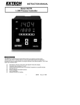
BARNSTEAD|THERMOLYNE CORPORATION
Type F62700
Furnace
OPERATION MANUAL
AND PARTS LIST
Series1075
Model No.
Voltage
Control
Display (°C or °F)
F62730
F62730-80
F62730-26
F62730-26-80
F62730-33
F62730-33-80
F62734
F62735
F62735-80
220-240V
220-240V
220-240V
220-240V
220-240V
220-240V
100V
120V
120V
Single Set Point
Programmable
Single Set Point
Programmable
Single Set Point
Programmable
Single Set Point
SIngle Set Point
Programmable
°C
°C
°C
°C
°C
°C
°C
°C
°C
LT1075X1 • 4/7/97
1
Table of Contents
F IMPORTANT INFORMATION
This manual contains important operating and safety information. The user must carefully
read and understand the contents of this manual prior to the use of this equipment.
Table of Contents
Safety Information ............................................................................................................................... 3
Alert Boxes ........................................................................................................................................... 3
Warnings .............................................................................................................................................. 4
Introduction .......................................................................................................................................... 5
Intended Use .................................................................................................................................... 5
General Usage ................................................................................................................................. 5
Principles of Operation ..................................................................................................................... 5
Single Set Point Temperature Controller .......................................................................................... 5
4 Ramp & 4 Dwell Programmable Controller ................................................................................... 6
General Specifications ......................................................................................................................... 8
Environmental Conditions ................................................................................................................ 8
Declaration of Conformity ..................................................................................................................... 9
Unpackaging ...................................................................................................................................... 10
Installation .......................................................................................................................................... 11
Site Selection: ................................................................................................................................ 11
General Operation of Furnace ............................................................................................................ 12
Operation of Single Set Point Temperature Control (Automatic) Models ............................................ 14
Models F62730, F62730-26, F62730-33, F62734, F62735 ............................................................ 14
Initial Startup .................................................................................................................................. 14
Adjustment of Parameters: (See Figure 1, page 4) ........................................................................ 14
Set Point Temperature ................................................................................................................... 14
Operation of 4 Ramp & 4 Dwell Programmable Models ..................................................................... 16
Models F62730-80, F62730-26-80, F62730-33-80, F62735-80 ..................................................... 16
Single Set Point Operation ............................................................................................................. 16
Programmed Operation .................................................................................................................. 16
Self Tuning Feature ........................................................................................................................ 20
Furnace Loading: ............................................................................................................................... 22
Preventative Maintenance .................................................................................................................. 23
General Cleaning Instructions ........................................................................................................ 24
Troubleshooting .................................................................................................................................. 25
Maintenance and Servicing ................................................................................................................ 27
Thermocouple Replacement (Type K) ........................................................................................... 28
Muffle (Heating Element) Replacement ......................................................................................... 28
Wiring Diagrams ................................................................................................................................. 29
Parts List ............................................................................................................................................ 31
Ordering Procedures .......................................................................................................................... 32
Material Safety Data Sheet ................................................................................................................ 33
Warranty ............................................................................................................................................. 36
2
Safety Information
Safety Information
Your Thermolyne furnace has been designed with function, reliability, and safety in mind. It is the user’s responsibility to install it in conformance with local electrical
codes. For safe operation, please pay attention to the
alert boxes throughout the manual.
Alert Boxes
WARNING
Warning alerts apply when there is a possibility of
personal injury.
CAUTION
Caution alerts apply when there is a possibility of
damage to the equipment.
NOTE
Notes alert the manual user to pertinent facts and
conditions.
HOT SURFACE
Hot surfaces alert you to a possibility of personal
injury if you come in contact with a surface during
use or for a period of time after use..
3
SAFETY INFORMATION
Warnings
WARNING
To avoid electrical shock, this furnace must:
1. Use a properly grounded electrical outlet of correct voltage and current handling capacity.
2. Disconnect from the power supply prior to maintenance and servicing.
3. Have the door switch operating properly.
To avoid burns, this furnace must:
1. Not be touched on the exterior or interior surfaces during use or for a period of time after use.
To avoid personal injury:
1. Do not use in the presence of flammable or combustible materials ; fire or explosion may result. This
device contains components which may ignite such material.
2. Refer servicing to qualified personnel.
3. This warning is presented for compliance with California Proposition 65 and other regulatory agencies
and only applies to the insulation in this product. This product contains refractory ceramic, refractory
ceramic fiber or fiberglass insulation, which can produce respirable dust or fibers during disassembly.
Dust or fibers can cause irritation and can aggravate pre-existing respiratory diseases. Refractory ceramic and refractory ceramic fibers (after reaching 1000°C) contain crystalline silica, which can cause
lung damage (silicosis). The International Agency for Research on Cancer (IARC) has classified refractory ceramic fiber and fiberglass as possibly carcinogenic (Group 2B), and crystalline silica as carcinogenic to humans (Group 1).
The insulating materials can be located in the door, the hearth collar, in the chamber of the product or under the
hot plate top. Tests performed by the manufacturer indicate that there is no risk of exposure to dust or respirable fibers resulting from operation of this product under normal conditions. However, there may be a risk of
exposure to respirable dust or fibers when repairing or maintaining the insulating materials, or when otherwise
disturbing them in a manner which causes release of dust or fibers. By using proper handling procedures and
protective equipment you can work safely with these insulating materials and minimize any exposure. Refer to
the appropriate Material Safety Data Sheets (MSDS) for information regarding proper handling and recommended protective equipment. For additional MSDS copies, or additional information concerning the handling
of refractory ceramic products, please contact the Customer Service Department at Barnstead|Thermolyne
Corporation at 1-800-553-0039.
4
Introduction
Introduction
Intended Use
The Type F62700 furnace is a general laboratory and
heat treating furnace. For optimum element life, it is suggested that this furnace be used for applications requiring temperatures from 400°F (204°C) to 1600°F (871°C)
for continuous use, or temperatures from 1600°F (871°C)
to 1832°F (1000°C) for intermittent use. Continuous use
is operating the furnace for more than 3 hours and intermittent use is operating the furnace for less than 3 hours.
The unit consists of: 1) muffle heating chamber, 2) a microprocessor control and 3) a door interlock relay for
user safety.
General Usage
Do not use this product for anything other than its intended usage.
Principles of Operation
The furnace chamber incorporates a heating element
that is embedded into the side walls and top and back of
heating chamber. The ceramic fiber oval muffle with four
heating surfaces creates even heat distribution within the
chamber. The temperature is controlled by a microprocessor control with a type K Chromel/Alumel Thermocouple. A fan is provided in the furnace to provide forced
air cooling for the temperature controller. A door safety
switch removes power to the heating elements whenever
the furnace door is opened.
Single Set Point Temperature Controller
One of the furnace’s controllers is a single set point control, with programmable over temperature protection
which enables the user to bring the furnace up to a preset point and hold the temperature.
5
INTRODUCTION
4 Ramp & 4 Dwell Programmable Controller
This controller consists of a microprocessor based threemode (Proportional, Integral, Derivative), programmable
temperature controller with “Fuzzy” logic capability, programmable over-temperature protection and appropriate
output switching devices to control the furnace. The digital
readout continuously displays chamber (upper display) and
setpoint (lower display) temperatures unless the “SEL” button is depressed.
The programmable control can be used as a single setpoint
control or as a programmable control.
6
Furnace Chamber
Temperature
Secret Key
Temperature Set Point
Cycle Light
Alarm Indicator
Down Button
Up Button
Scroll Button
Figure 1
Single Set Point Temperature Controller
Output Indicator
Furnace Chamber
Temperature
Non-functional
Alarm Indicator
Non-functional
Set point Temperature
Enter Button
“SEL” Button
Down Button
Up Button
Figure 2
4 Ramp & 4 Dwell Programmable Controller
7
General Specifications
MODEL NUMBER
F62730,
F62730-80
F62730-26,
F62730-26-80,
F62730-33
F62730-33-80
F62734
F62735,
F62735-80
OVERALL
WIDTH
23-1/2
(59.7 CM)
23-1/2
(59.7 CM)
23-1/2
(59.7 CM)
23-1/2
(59.7 CM)
DIMENSIONS
HEIGHT
16-1/4
(41.3 CM)
16-1/4
(41.3 CM)
16-1/4
(41.3 CM)
16-1/4
(41.3 CM)
IN. (CM)
DEPTH
18-3/4
(47.6 CM)
18-3/4
(47.6 CM)
18-3/4
(47.6 CM)
18-3/4
(47.6 CM)
CHAMBER
WIDTH
11-1/2
(29.2 CM)
11-1/2
(29.2 CM)
11-1/2
(29.2 CM)
11-1/2
(29.2 CM)
DIMENSIONS
HEIGHT
7-1/2
(19.1 CM)
7-1/2
(19.1 CM)
7-1/2
19.1 CM)
7-1/2
19.1 CM)
IN. (CM.)
DEPTH
11-1/2
(29.2 CM)
11-1/2
(29.2 CM)
11-1/2
(29.2 CM)
11-1/2
(29.2 CM)
WEIGHT
LBS.
(KG)
55 LBS
(25 KG)
55 LBS
(25 KG)
55 LBS
(25 KG)
55 LBS
(25 KG)
VOLTS
220-240
220-240
100
120
AMPS
6.2
6.2
14.8
12.4
WATTS
1488
1488
1488
1488
FREQ.
PHASE
50/60
1
50/60
1
50/60
1
50/60
1
CONTINUOUS
1832°F
(1000°C)
1832°F
(1000°C)
1832°F
(1000°C)
1832°F
(1000°C)
ELECTRICAL
RATINGS
OPERATING
TEMP.
Environmental Conditions
Operating: 17°C - 27°C; 20% to 80% relative humidity, non-condensing. Installation Category II
(over-voltage) in accordance with IEC 664. Pollution Degree 2 in accordance with IEC 664.
Altitude limit: 2,000 meters.
Storage: -25°C to 65°C; 20% to 80% relative humidity.
8
Declaration of Conformity
Declaration of Conformity
(for -33 models only)
Barnstead|Thermolyne hereby declares under its sole responsibility that this product conforms with the technical
requirements of the following standards:
EMC: EN 50081-1 Generic Emission Standard; EN
50082-1 Generic Immunity Standard;
Safety: IEC 1010-1-92 Safety requirements for electrical equipment for measurement,
control, and laboratory use; Part I: General Requirements
IEC1010-2-010 Part II: Particular requirements
for laboratory equipment for the heating
of materials
per the provisions of the Electromagnetic Compatability
Directive 89/336/EEC, as amended by 92/31/EEC and
93/68/EEC, and per the provisions of the Low Voltage Directive 73/23/EEC, as amended by 93/68/EEC.
The authorized representative located within the European Community is:
European Manager
Barnstead|Thermolyne
Saarbrückener Str. 248
D-38116 Braunschweig
Germany
Copies of the Declaration of Conformity are available
upon request.
9
Unpackaging
Unpackaging
Visually check for any physical damage to the shipping container. Inspect the equipment surfaces that are adjacent to
any damaged area. Open the furnace door and remove
packing material from inside the furnace chamber. Vacuum
the chamber prior to use to remove the insulation dust due
to shipping.
The furnace is supplied with two hearth plates. Place the
hearth plates on the bottom of the chamber.
Install ceramic sleeve into top vent hole on furnace case.
Retain the original packaging material if re-shipment is foreseen or required.
10
Installation
Installation
Site Selection:
Install furnace on a sturdy surface and allow adequate
space for ventilation.
CAUTION
Be sure ambient temperature does not exceed
104°F (40°C). Ambients above this level may result in damage to the controller.
Allow at least six inches of space between the furnace and any combustible surface. This permits
the heat from the furnace case to escape so as not
to create a possible fire hazard.
The electrical specifications are located on the specification plate on the back of the furnace. Consult Barnstead/
Thermolyne if your electrical service is different than
those listed on the specification plate. Prior to connecting
your Type F62700 furnace to your electrical supply, be
sure the front power switch is in the “OFF” position.
ObservŇThese Warnings Before Operating
Your Furnace:
WARNING
Do not use in the presence of flammable or combustible chemicals. Fire or explosion may result;
this device contains components which may ignite
such materials.
WARNING
To avoid burns, this furnace must not be touched
on the exterior or interior furnace surfaces during
use or for a period of time after use.
11
General Operation of Furnace
General Operation of Furnace
WARNING
To avoid electrical shock, this furnace must:
1. Use a properly grounded electrical outlet of correct voltage and current handling capacity.
2. Disconnect from the power supply prior to maintenance and servicing.
3. Have the door switch operating properly.
To avoid personal injury:
1. Do not use in the presence of flammable or combustible materials ; fire or explosion may result. This
device contains components which may ignite such material.
2. Refer servicing to qualified personnel.
3. This warning is presented for compliance with California Proposition 65 and other regulatory agencies
and only applies to the insulation in this product. This product contains refractory ceramic, refractory
ceramic fiber or fiberglass insulation, which can produce respirable dust or fibers during disassembly.
Dust or fibers can cause irritation and can aggravate pre-existing respiratory diseases. Refractory ceramic and refractory ceramic fibers (after reaching 1000°C) contain crystalline silica, which can cause
lung damage (silicosis). The International Agency for Research on Cancer (IARC) has classified refractory ceramic fiber and fiberglass as possibly carcinogenic (Group 2B), and crystalline silica as carcinogenic to humans (Group 1).
The insulating materials can be located in the door, the hearth collar, in the chamber of the product or under the
hot plate top. Tests performed by the manufacturer indicate that there is no risk of exposure to dust or respirable fibers resulting from operation of this product under normal conditions. However, there may be a risk of
exposure to respirable dust or fibers when repairing or maintaining the insulating materials, or when otherwise
disturbing them in a manner which causes release of dust or fibers. By using proper handling procedures and
protective equipment you can work safely with these insulating materials and minimize any exposure. Refer to
the appropriate Material Safety Data Sheets (MSDS) for information regarding proper handling and recommended protective equipment. For additional MSDS copies, or additional information concerning the handling
of refractory ceramic products, please contact the Customer Service Department at Barnstead|Thermolyne
Corporation at 1-800-553-0039.
12
GENERAL OPERATION
OF
FURNACE
Power Switch:
Switch power switch to the “ON” position. The switch will
illuminate when power is on.
CAUTION
If the power supply must be disconnected from the
furnace at any time, be sure the chamber temperature is 500°C or less before doing so.
FAN:
The fan located in the rear of the control section will run
continuously as long as power is supplied to the furnace,
even when the furnace power switch is OFF. This serves
to remove residual heat after the furnace is turned OFF
so the heat does not cause damage to sensitive electronic components.
Cycle Indicator:
The amber cycle light will illuminate whenever the power
is being applied to the elements.
WARNING
To avoid electrical shock, this furnace must have
the door switch operating properly.
Door Safety Switch:
The door safety switch removes power from the heating
elements when the door is opened. Open and close
door a few times, note that the amber cycle light will go
out while the door is open. If this condition is not true,
consult the troubleshooting section before proceeding.
Digital Readout:
The Digital Readout continuously displays chamber
(upper display) and set point (lower display) temperatures.
13
Operation of Single Set Point
Temperature Control
(Automatic) Models
NOTE
The temperature control in these models is a
single set-point device. By using the “up” or
“down” push buttons a specific temperature can
be chosen. The control will cause the furnace
chamber to heat to the chosen temperature and
hold it at this temperature until you turn off the
power switch or select another temperature.
Operation of Single Set
Point Temperature Control
(Automatic) Models
Models F62730, F62730-26, F62730-33, F62734, F62735)
This furnace controller consists of a microprocessor based
three-mode (Proportional, Integral, Derivative), single
setpoint temperature controller. The controller features programmable over temperature protection and thermocouple
break protection.
Initial Startup:
NOTE
When performing the following steps remember
that if more than eight to ten seconds elapse before the buttons are used again, the display
screen will automatically switch back to displaying chamber temperature. If this happens, light
up the front panel again and step through each
parameter until you reach the point at which the
interruption occurred. The parameter values you
checked earlier, however, will not be lost or altered. Holding down on the scroll button allows
longer viewing time.
CAUTION
Do not exceed limitations for continuous or intermittent operating temperature shown in the
General Specifications. Exceeding these limits
will result in severely reduced heating element
life.
When the power switch is turned on the controller will perform a self-test to make sure controller is operating properly. (If all four 1’s do not light up or fails to go to “8888”
contact Thermolyne.)
Adjustment of Parameters: (See Figure 1,
page 4)
To illuminate down ▼ button, scroll
▲ button, touch anywhere on front panel.
button, and up
Set Point Temperature:
Push up ▲ button or down ▼ button, to modify temperature
set point (lower digital display).
Temperature Indication:
Push scroll
button once, “°C” will appear. This indicates temperature measurement. (Contact Thermolyne if
control needs to be changed to °F.)
Tuning:
This control incorporates a self tuning feature which determines the optimum control parameters for the best temperature accuracy.
Push scroll
button until “tunE” appears. To start tuning function push ▲ button. To stop tuning function push ▼
button.
14
OPERATION
OF
SINGLE SET POINT TEMPERATURE CONTROL (AUTOMATIC) MODELS
When the tuning process is started the lower display will
flash “tunE” along with the furnace temperature set
point. During tuning the temperature set point cannot be
changed. To change temperature set point “tunE” must
be turned “OFF”.
NOTE
If the power to the furnace is “turned off” or interrupted while in “tuning,” upon return of power to
the furnace, the controller display will indicate
“LINE FAIL” because sampled data could be
questionable. To restart tuning, refer to “Tuning”
procedure.
If the controller cannot maintain temperature set
point “tunE FAIL” will appear on display. First, correct problem for not maintaining temperature set
point, then restart “tuning” procedure.
High Alarm (Over Temperature Protection OTP):
Push scroll button until “AL.SP” (Alarm Set Point)
appears. The lower display should indicate 1010°C.
Depress either the “UP” or “DOWN” push button to select the OTP value you desire. Thermolyne recommends
that you set the value either at the maximum operating
temperature of the furnace or a value of 20 degrees
above your working temperature if you desire to provide
protection for your workload.
NOTE
HiAL- HIGH ALARM. (over-temperature protection, OTP)
The controller is fitted with a mechanical relay
which is de-energized in the alarm mode. This relay, when de-energized, removes power from the
heating elements. If the primary control circuit fails,
the OTP will control the furnace temperature at the
preset value you have entered. It does not shut off
the furnace, but will maintain the chamber temperature at that value.
15
Operation of 4 Ramp & 4
Dwell Programmable Models
Operation of 4 Ramp & 4 Dwell
Programmable Models
Models F62730-80, F62730-26-80, F62730-3380, F62735-80)
WARNING
To avoid electrical shock, this furnace must
have the door switch operating properly.
NOTE
For optimum control of a single set point operation, set the “CTrL” parameter to “FUZY” to take
advantage of the controller’s fuzzy logic capabilities.
This controller consists of a microprocessor based threemode (Proportional, Integral, Derivative), programmable
temperature controller with “Fuzzy” logic capability, programmable over-temperature protection and appropriate
output switching devices to control the furnace. The digital
readout continuously displays chamber (upper display) and
setpoint (lower display) temperatures unless the “SEL” button is depressed.
The programmable control can be used as a single set
point control or as a programmable control.
Single Set Point Operation
NOTE
The furnace will begin to heat to the current set
point temperature when you turn the power
switch “ON.” To examine the control parameters
without heating the furnace, depress and hold
the “DOWN”button until the setpoint (lower) display reads “20”.
To use as a single set point control simply push “UP” or
“DOWN” button to choose a specific temperature.
1.
The set point temperature presently set in the
control will be read out on the lower display
2.
To change this set point, depress the “UP” or
“DOWN” button until the desired set point value
is displayed, then release the button.
3.
At this point, the furnace will begin to heat if the
new set point temperature you have chosen is
higher than the present chamber temperature.
Programmed Operation
Control Parameters
You can gain access to the control parameters by holding
the “SEL” button depressed for about 3 seconds. “LoCt” will
be displayed in the upper display.
16
OPERATION OF 4 RAMP & 4 DWELL PROGRAMMABLE MODELS
NOTE
When examining the parameters, if you depress
and release either the “SEL,” “UP,” or “DOWN” buttons and more than 1 minute elapses before the
buttons are used again, the display screen will automatically switch to displaying chamber temperature. If this happens, you will have to step through
each parameter until you reach the point at which
the interruption occurred. The parameter values
you checked earlier, however, will not be lost or altered.
Depressing “SEL” once again shows the next parameter
and its current value on the display. The parameter value
can either be modified with the buttons or left unmodified.
Pressing the enter button (>) will allow you to modify the
current value using the “Up” and “Down” buttons. Press
the enter button again to set the new value as the current
value. (See “Programming Controller” for information on
programming.)
The control parameters in order are:
LoCt - Parameter lock level. Determines the number of
parameters displayed when you press “SEL”. It should
be set to “0002.” If it does not, set to “0002.”
Nod - Mode. By pushing “UP” or “DOWN” buttons, this
can be set to “Auto” or “NAn” (Manual). Set to “Auto”. In
Manual mode, you must enter values to control the furnace chamber temperature.
At - Autotuning feature. Will automatically set optimum
P.I.D. values for your process. For Tuning, set to “on.”
For normal operation, set to “oFF.”
StAt - Status. Displays current status of program and
cannot be changed.
Tine - Time. Displays the time remaining in the current
program.
ProG - Program options. Can be set to one of three options: “oFF”, “rUn” or “hold”. “oFF” will stop any running
program and reset the program to the beginning. “rUn”
will start a program from the beginning or resume a program from “hold” from the point it was held. “hold” will interrupt a running program without resetting the program
to the beginning.
Sü-1 - Set point 1. The temperature at which the first
ramp is aiming and at which the first dwell will be held.
tN1r - Ramp time 1. The time the controller will take to
charge the chamber temperature from its present temperature to the value of Set point 1. This time may be limited by the physical capabilities of the furnace.
tN1S - Dwell time 1. The length of time the controller will
hold the furnace at the Set point 1 temperature.
17
OPERATION OF 4 RAMP & 4 DWELL PROGRAMMABLE MODELS
Sü-2 - Set point 2.
tN2r - Ramp time 2.
tN2S - Dwell time 2.
Sü-3 - Set point 3.
tN3R - Ramp time 3.
tN3S - Dwell time 3.
Sü-4 - Set point 4.
tN4r - Ramp time 4.
tN4S - Dwell time 4.
P-on - Power-on start. Push the “Up” or “Down” Buttons to
set to “Yes” or “No.” When set to “Yes,” your furnace will
immediately begin running the set program when you power
on your furnace. For most applications, set to “No.”
NOTE
Overtemperature protection
The controller is fitted with a mechanical relay
which is de-energized in the alarm mode. This
relay, when de-energized, removes power from
the heating elements. If the primary control circuit fails, the OTP will control the furnace temperature at the value you have entered for AL11.
It does not shut off the furnace, but will maintain
the chamber temperature at that value.
The next three parameters - Proportional band, Integral and
Derivative - are the three control parameters of a P.I.D. control system. The values for these parameters are set during
the tuning process. You should not change them; doing so
may cause your controller to operate incorrectly.
P - Proportional band
i - Integral
d - Derivative
AL1T - Alarm type. This parameter determines how the
controller responds to any alarm input. It should display
“0031.” If it does not, set it to “0031.”
AL11 - Furnace overtemperature alarm. This parameter
determines the absolute upper limit on the
furnace
chamber temperature. We recommend a setting of
“1000°C” since 1000°C is the maximum temperature
your furnace can obtain without damage to furnace components. You may wish to set the parameter lower if you need
to ensure a crucial process is protected from high
temperature.
18
AL12 - High deviation alarm. This parameter determines
OPERATION OF 4 RAMP & 4 DWELL PROGRAMMABLE MODELS
how far the furnace chamber temperature
can rise
above your set point. We recommend a setting of 20;
since a P.I.D. control process involves some degree of
temperature overshoot, a setting of less than 20 may interfere with the function of your controller.
CAUTION
Remember that whenever the power switch is
turned “ON,” the furnace will begin to heat at the
set point temperature that was previously set. This
value will remain unchanged for up to a year without power being applied to the control.
LooP - Thermocouple break alarm detection time. For
proper operation of your furnace, this
parameter
should be set to “0.00”. If it is not, set it to “0.00”.
CTrL - Control type. Push the “Up” or “Down” buttons to
set to “Pid” or “FUZY”. Programmed
operation requires P.I.D. control. Single set point operation will
achieve better control using Fuzzy
logic control.
Programming Controller
This controller allows you a maximum of 4 ramp and 4
dwell segment combinations, thus enabling 4 different set
point levels to be achieved. Each ramp is programmed
by specifying the ending temperature level and the required time to ramp to that temperature. The controller
then automatically calculates the ramp rate required to
attain the ending temperature level based on the desired
ramp time. Dwell segments then can be attached to each
temperature level to hold that temperature for a specified
amount of time.
To run a program, first determine your ramp times, ending temperature levels and dwell times. It is helpful to
graph your program out for ease of loading the program
into the controller.
Make sure “ProG” (program options) is set to “oFF” (to
stop the program) when entering program values.
Push “SEL” button until “Sü-1” is displayed. Push the Enter button (>) to select the current value. Push “UP” or
“DOWN” button and set Set point 1 in °C. Push the Enter
button to enter the set value as the current value.
Push “SEL” button until “TN1r” is displayed. Push the En-
19
OPERATION OF 4 RAMP & 4 DWELL PROGRAMMABLE MODELS
NOTE
If you desire to skip a ramp or dwell segment,
follow this procedure:
for a dwell segment, enter a setting of “0” minutes.
for a ramp segment, enter a setting of “00.00”
hour.minutes. This will cause controller to skip to
next segment as fast as the furnace can heat or
cool down.
ter button (>) to select the current value. Push “UP” or
“DOWN” button and set Ramp time 1 in hours and minutes
in the format “X.XX”
(hour.minutes). This is the time
Ramp 1 will take to reach Set point 1. Push the Enter button
to
enter the set value as the current value.
Push “SEL” button until “TH1S” is displayed. Push the Enter
button (>) to select the current value.
Push “UP” or
“DOWN” button and set Dwell time 1 in hours and minutes
in the format “X.XX”
(hour.minutes). Push the Enter button to enter the set value as the current value.
Set “Sü-2” “TN2r” “TN2S” “Sü-3” “TN3r” “TN3S” “Sü-4”
“TN4r” and “TN4S” in the same manner as “Sü-1” “TN1r”
“TN1S”.
NOTE
The temperature control in these models is a
programmable “and” automatic single set point
device. When the program has ended, the controller will maintain the chamber temperature at
a value equal to the last programmed level (Set
point 4) until the program is canceled. It will not
automatically cool to ambient unless Set point 4
is set at ambient. When a program is canceled,
the controller will maintain the chamber temperature at a value equal to the single set point
mode set point.
Program Execution
Push “SEL” button until “ProG” is displayed. Pushing “UP”
or “DOWN” button, select “run.” When “run” is selected, the
program will start from the actual furnace temperature at
that point in time.
Set point
While the program is in “run” or “Hold,” the set point shown
on the bottom display is the current working set point.
Program End
When the program ends, the controller will hold the furnace
at the value of Set point 4 until you stop the program
Program Stop
To stop program, push “SEL” button until “ProG” is displayed. Push “UP” or “DOWN” button until “oFF” is displayed. This will terminate program.
Self Tuning Feature
This programmable control has an automatic tuning feature
which installs optimum tuning parameters to give the best
temperature accuracy with your load and set point or program. No manual loading of tuning parameters is needed.
Barnstead|Thermolyne highly recommends using this
feature to provide the best temperature accuracy the
controller can attain. Use this feature the first time you
use your furnace and each time you change your set point
20
OPERATION OF 4 RAMP & 4 DWELL PROGRAMMABLE MODELS
or program or the type of load you are heating. To use
the Tuning feature:
NOTE
For processes which cannot tolerate the overshoot
naturally generated during the tuning process, select “Lo” rather than “on” for the “AT” setting. The
“Lo” setting will tune your furnace at a temperature
below your set point, then apply the result to your
set point. This approach prevents the necessary
tuning overshoot from exceeding your actual set
point.
1.
Select the temperature at which you intend to
operate. If you will be running a program,
enter the value of Set point 1 as a single set
point.
2.
Load your furnace with a characteristic sample of
the load you will be heating.
3.
Push “SEL” button until “AT” is displayed, then
push “UP” or “DOWN” button to turn “AT” “on.”
During the operation, “TunE” flashes in the lower display.
Do not make any adjustments to the controller parameters during this period. The self tuning is finished when
“TunE” no longer flashes in the lower display.
Self tuning will calculate values for:
Proportional band - P
Integral - I
Derivative - d
•
Self tuning cannot be initiated while running a
program.
•
A power failure will cause the AT parameter to
revert back to “OFF”. (Reset tune parameter to
“ON” using the “UP” button).
•
In the case of alarm conditions during tuning,
those conditions will flash alternately with
“TunE.”
The next time you use your furnace, push “SEL” button
until “AT” is displayed, then push “UP” or “DOWN” button
to turn tune “oFF.”
Furnace Loading:
1.
For best results use only the center 2/3
of the furnace chamber.
21
Furnace Loading
CAUTION
Do not overload your furnace chamber. If the
load is to be heated uniformly it should not occupy more than the center two-thirds of the furnace chamber. Failure to observe this caution
could result in damage to furnace components.
2.
If you are heating a number of small parts,
spread them throughout the center twothirds of the furnace chamber.
3.
Keep objects away from thermocouple.
4.
Use insulated tongs and mittens when
loading and unloading furnace.
5.
Always wear safety glasses.
6.
Use the hearth plates supplied to protect
bottom of chamber. Part # PH421X1.
7.
Do not exceed a load of 25 lbs. in the furnace chamber.
Preventative Maintenance
22
Preventative Maintenance
WARNING
This warning is presented for compliance with California Proposition 65 and other regulatory agencies and only
applies to the insulation in this product. This product contains refractory ceramic, refractory ceramic fiber or
fiberglass insulation, which can produce respirable dust or fibers during disassembly. Dust or fibers can cause
irritation and can aggravate pre-existing respiratory diseases. Refractory ceramic and refractory ceramic fibers
(after reaching 1000°C) contain crystalline silica, which can cause lung damage (silicosis). The International
Agency for Research on Cancer (IARC) has classified refractory ceramic fiber and fiberglass as possibly
carcinogenic (Group 2B), and crystalline silica as carcinogenic to humans (Group 1).
The insulating materials can be located in the door, the hearth collar, in the chamber of the product or under the
hot plate top. Tests performed by the manufacturer indicate that there is no risk of exposure to dust or respirable fibers resulting from operation of this product under normal conditions. However, there may be a risk of
exposure to respirable dust or fibers when repairing or maintaining the insulating materials, or when otherwise
disturbing them in a manner which causes release of dust or fibers. By using proper handling procedures and
protective equipment you can work safely with these insulating materials and minimize any exposure. Refer to
the appropriate Material Safety Data Sheets (MSDS) for information regarding proper handling and recommended protective equipment. For additional MSDS copies, or additional information concerning the handling
of refractory ceramic products, please contact the Customer Service Department at Barnstead|Thermolyne
Corporation at 1-800-553-0039.
WARNING
Disconnect from the power supply prior to maintenance and servicing.
Refer servicing to qualified personnel.
This unit is equipped with a venting system on the top of the furnace. This is for the removal of fumes from the
chamber of the unit. Contamination is a major cause of element failure, therefore, when possible remove the
fume forming material before heating. (e.g., cleaning cutting oil from tool steel.)
23
PREVENTATIVE MAINTENANCE
Housekeeping is vital to your electric furnace - KEEP IT
CLEAN. Run your furnace up to 1600°F empty occasionally
to burn off the contamination that may exist on the insulation and elements. Maintain 1600°F for at least 4 hrs. to insure complete ashing of foreign materials.
Element life is reduced somewhat by repeated heating and
cooling. If the furnace is to be used again within a few
hours, it is best to keep it at the operating temperature or at
a reduced level such as 500°F (260°C).
General Cleaning Instructions
Wipe exterior surfaces with lightly dampened cloth containing mild soap solution.
The Troubleshooting section is intended to aid in defining
and correcting possible service problems. When using the
chart, select the problem category that resembles the malfunction; then proceed to the possible causes category and
take necessary corrective action.
24
Troubleshooting
PROBLEM
POSSIBLE CAUSES
CORRECTIVE ACTION
The power light does not
illuminate.
The furnace is not connected
to power supply.
Check furnace connection to
power source.
ON and OFF power switch
defective.
Replace power switch.
The furnace is not connected to
the power supply.
Check furnace connection
to power source.
Blown fuses.
Replace fuses.
No power.
Check power source and
fuses or breakers.
Thermocouple is open or
thermocouple leads reversed.
Replace thermocouple or check
thermocouple connections.
Controller malfunction.
Verify and correct all parameters
and configuration values.
If malfunction persists,
replace control.
Element burned out.
Replace muffle (element).
Solid state relay defective.
Replace solid state relay.
Door switch malfunction.
Re-align or replace door switch.
Low line voltage.
Install line of sufficient size and
proper voltage. (Isolate furnace
from other electrical loads.)
Heavy load in chamber.
Lighten load in chamber to allow
heat to circulate.
Wrong heating element.
Install proper element.
Wired improperly.
Check wiring diagram for correct
wiring of your furnace.
POSSIBLE CAUSES
One side of element is burned out
on 120V or 100V unit.
CORRECTIVE ACTION
Replace muffle (element).
Fan does not operate
The furnace does not heat.
Slow heatup.
PROBLEM
25
TROUBLESHOOTING
Door switch does not cut
Door switch is not functioning.
Re-align or replace door
safety switch.
Repeated element burnout.
Heating harmful materials.
Clean up spills in and on chamber.
Ventilate chamber by leaving
top vent slightly open when
heating known harmful reagents.
Wrong element.
Install proper element.
Oxidized thermocouple.
Replace thermocouple.
Contamination present from
previous burnout.
Clean and/or replace
insulation material.
Wired improperly.
Check wiring diagram for correct
wiring of your furnace.
Oxidized or contaminated
thermocouple.
Replace thermocouple.
Poor thermocouple connection.
Tighten connections.
Solid state relay malfunction.
Replace solid state relay.
Improper loading procedures.
Use proper loading procedures.
Poor ventilation of base or
cooling fan failed.
Clear area around furnace base
or replace cooling fan.
Control out of calibration.
Contact Barnstead/Thermolyne.
Thermocouple connections
reversed.
Reconnect thermocouple
correctly.
P.I.D. values invalid.
Re-tune control.
Control malfunction.
Verify and correct all parameter
and configuration values.
If malfunction persists, replace
control.
Inaccurate temperature readout.
26
WARNING
Maintenance and Servicing
This warning is presented for compliance with California Proposition 65 and other regulatory agencies and only
applies to the insulation in this product. This product contains refractory ceramic, refractory ceramic fiber or
fiberglass insulation, which can produce respirable dust or fibers during disassembly. Dust or fibers can cause
irritation and can aggravate pre-existing respiratory diseases. Refractory ceramic and refractory ceramic fibers
(after reaching 1000°C) contain crystalline silica, which can cause lung damage (silicosis). The International
Agency for Research on Cancer (IARC) has classified refractory ceramic fiber and fiberglass as possibly
carcinogenic (Group 2B), and crystalline silica as carcinogenic to humans (Group 1).
The insulating materials can be located in the door, the hearth collar, in the chamber of the product or under the
hot plate top. Tests performed by the manufacturer indicate that there is no risk of exposure to dust or respirable fibers resulting from operation of this product under normal conditions. However, there may be a risk of
exposure to respirable dust or fibers when repairing or maintaining the insulating materials, or when otherwise
disturbing them in a manner which causes release of dust or fibers. By using proper handling procedures and
protective equipment you can work safely with these insulating materials and minimize any exposure. Refer to
the appropriate Material Safety Data Sheets (MSDS) for information regarding proper handling and recommended protective equipment. For additional MSDS copies, or additional information concerning the handling
of refractory ceramic products, please contact the Customer Service Department at Barnstead|Thermolyne
Corporation at 1-800-553-0039.
WARNING
Disconnect from the power supply prior to maintenance and servicing.
Refer servicing to qualified personnel.
Replace fuses with the same type and rating.
Thermocouple Replacement (Type K)
a.
b.
c.
d.
e.
f.
Disconnect from power supply.
Set furnace on its door.
Remove (one piece) top, back and bottom cover.
Remove retaining clip from the thermocouple and pull the thermocouple straight out from the chamber.
Disconnect thermocouple lead ends from back of the controller and remove the thermocouple.
Reinstall thermocouple by reversing steps A through E.
27
MAINTENANCE AND SERVICIMG
Muffle (Heating Element) Replacement
NOTE
Perform only maintenance described in this
manual. Contact an authorized dealer or our factory for parts and assistance.
a.
b.
c.
d.
e.
f.
g.
h.
i.
NOTE
Make sure yellow thermocouple lead wire is connected to terminal #9 on back of the controller.
Make sure red thermocouple lead wire is connected to terminal #10 on back of the controller.
j.
k.
On the 120V or 100V muffle there are three element
lead wires. Connect the front and the back element
lead wires to the mechanical relay. Connect the middle
element lead wire to the solid state relay.
Make sure the exposed section of the T/C lead
wires are not contacting each other.
On the 230V and 240V muffles there are two element
lead wires. Connect the front element lead wire to mechanical relay. Connect the back element lead wire to
the solid state relay.
NOTE
Make sure the black insulation sleeving covers
the exposed portion of the element lead wires.
NOTE
Make sure the exposed section of the T/C lead
wires are not contacting each other.
28
Disconnect from power supply.
Set furnace on its door.
Remove (one piece) top, back and bottom cover.
Disconnect element lead wires from relays. (Note
placement and connection of.)
Remove clip from thermocouple and pull thermocouple
out of muffle.
Remove metal retaining band from defective muffle.
Loosen top adjustment bracket and remove defective
muffle.
Insert new muffle with vent hole facing the top of unit.
Readjust top bracket to fit snugly up against muffle.
Make sure muffle is laying flush against front case section.
Reinstall metal retaining band and tighten until muffle
seats firmly into case section.
Reconnect element lead wires.
l.
m.
n.
Reinstall the thermocouple and the retaining clip.
Reinstall the cover section.
Set the furnace upright and test the operation of the
furnace.
S2
5
11
TC-
CN1
2
3
Wiring Diagram
Single Set Point Temperature Control Models
F62735
F62734 AND
USED WITH
+
1
4
L1
RY1
RY2
L2
B1
H1
S1
F62730-26
F62730-33
F62730
CYCLE
DS1
FL1
G
L2
L1
F62730-33
G
L2
L1
GND
GND
THERMOCOUPLE
F1
DOOR SWITCH
TC1
HEATING ELEMENT
SOLID STATE RELAY
H1
RY1
S2
FILTER, EMI
FL1
RELAY, DPST, N.O.
SWITCH
FUSE (TYPE NON-TIME LAG,
250 VOLT, 10 AMP)
F1
RY2
S1
BLOWER FAN
PILOT LIGHT, NEON
LOAD
TC1
TC+
10
9
8
3
12
7
2
4
6
1
CONTROL
B1
DS1
DESCRIPTION
CN1
NO.
REF.
DIAGRAM COMPONENT LIST
LINE
LINE
Wiring Diagrams
LINE
29
30
S2
9
10
4
5
TC-
CN1
Wiring Diagram
4 Ramp & 4 Dwell Programmable Models
USED WITH
F62735-80
+
4
3
L1
1
2
RY1
RY2
L2
B1
H1
S1
DS1
F62730-33-80
F62730-26-80
F62730-80
CYCLE
DOOR SWITCH
THERMOCOUPLE
TC1
FL1
SWITCH
S2
F1
RELAY, DPST, N.O.
S1
SOLID STATE RELAY
HEATING ELEMENT
FILTER, EMI
RY2
RY1
H1
FL1
L1
G
L2
F62730-33-80
GND
G
L2
L1
GND
PILOT LIGHT, NEON
FUSE (TYPE NON-TIME LAG,
250 VOLT, 10 AMP)
DS1
F1
LOAD
TC1
TC+
8
3
12
7
11
6
2
1
CONTROL
BLOWER FAN
CN1
DESCRIPTION
B1
NO.
REF.
DIAGRAM COMPONENT LIST
LINE
LINE
WIRING DIAGRAMS
LINE
Replacement Parts List
Replacement Parts List
Listed below are the common replacement parts for all models of the F62700 furnace.
PART
PART NO.
Temperature Control (Single Set Point Models) CN71X45
Temperature Control (4 Ramp & 4 Dwell Programmable Models) CN71X62
Muffle Heating Element 100V
EL1075X3A
Muffle Heating Element 120V
EL1075X1A
Muffle Heating Element 220-240V
EL1075X2A
Solid State Relay
RYX34
Mechanical Relay 120V, 100V
RYX56
Mechanical Relay 220-240V
RYX57
On/Off Switch 120V SWX143
On/Off Switch 220-240V
SWX144
Fan 120V, 100V
FAX3
Fan 220-240V
FAX4
Door Switch
SWX163
Thermocouple
TC517X1A
Door Insulation
JC517X1
Hearth Plate (2 required)
PH421X1
Pilot light, 100V & 120V
PLX103
Pilot light, 220-240V PLX104
Door Assembly, with insulation
DR1075X1A
Fuses, Type Non-Time Lag, 250 Volt,
10 Amp
FZX30
WARNING
Replace fuses with the same type and rating.
31
Ordering Procedures
Ordering Procedures
Please refer to the Specification Plate for the complete
model number, serial number, and series number when requesting service, replacement parts or in any correspondence concerning this unit.
All parts listed herein may be ordered from the
Barnstead|Thermolyne dealer from whom you purchased
this unit or can be obtained promptly from the factory. When
service or replacement parts are needed we ask that you
check first with your dealer. If the dealer cannot handle your
request, then contact our Customer Service Department at
319-556-2241 or 800-553-0039.
Prior to returning any materials to Barnstead|Thermolyne
Corp., please contact our Customer Service Department for
a “Return Goods Authorization” number (RGA). Material returned without a RGA number will be refused. Minimum invoice: $25.
32
Material Safety Data Sheet
Thermal Ceramics
Material Safety Data Sheet
Date Revised:
7/2/91
PRODUCT IDENTIFICATION
Trade Name(s):
Generic Name:
Chemical Name:
Manufacturer:
Address:
City:
CERAFIBER
REFRACTORY CERAMIC FIBER INSULATION
ALUMINA SILICA
Thermal Ceramics
P.0. BOX 923, 2102 Old Savannah Road
Augusta
State:
Georgia
Zip: 30903
CAS #:
Formula:
Telephone:
65997-17-3
MIXTURE
(404) 796-4200
PRODUCT INGREDIENTS
INGREDIENT NAME
REFRACTORY CERAMIC FIBER
CAS NUMBER
%
PEL and TLV (except as noted)
65997-17-3
100
EXPOSURE GUIDELINE
5mg/M- NUISANCE RESPIRABLE - OSHA
1 FIBER/CC
10mg/M- NUISANCE TOTAL - ACGIH
CRYSTALLINE SILICA (CRISTOBALITE) WILL FORM “AFTER SERVICE” AT TEMPERATURES >1000°C.
14464-46-1
>20
0.05 mg/M- OSHA Respirable Dust
PHYSICAL DATA
Appearance and Odor:
Boiling Point:
Vapor Pressure:
Water Solubility (%):
Vapor Density (Air= l):
WHITE FIBER-NO ODOR.
NA
NA
NIL
NA
Evaporation Rate (NA = 1):
Specific Gravity (water = 1 ):
Melting Point:
% Volatile by Volume:
NA
2.6
>3000°F
0
FIRE AND EXPLOSION DATA
Flash Point (Method):
NONFLAMMABLE
NFPA Flammable/Combustible Liquid Classification:
NA Flammable Limits: LEL: NA %
UEL:
NA %
Auto-Ignition Temperature:
NA
HEALTH HAZARDS
Summary/Risks
Summary: EXPOSURE TO DUST FROM THIS PRODUCT SHOULD BE MINIMIZED. ANIMAL INHALATION AND ARTIFICIAL IMPLANTATION STUDIES HAVE REPORTED THE DEVELOPMENT OF TUMORS. BASED ON PRELIMINARY RESULTS, A NOTICE OF
SUBSTANTIAL RISK HAS BEEN FILED WITH THE EPA ACCORDING TO SECTION 8(e) OF THE TOXIC SUBSTANCES CONTROL
ACT. BASED ON ANIMAL STUDIES, IARC HAS CLASSIFIED RCF AS POSSIBLY CARCINOGENIC FOR HUMANS (2B). DATA
FROM HUMAN EPIDEMIOLOGICAL STUDIES IS INSUFFICIENT. THIS SUBSTANCE OR MIXTURE HAS NOT BEEN CLASSIFIED
A CARCINOGEN BY NTP OR OSHA.
Medical conditions which may be aggravated: AS WITH ANY DUST, PRE-EXISTING UPPER RESPIRATORY AND LUNG DISEASES
33
MATERIAL SAFETY DATA SHEET
MAY BE AGGRAVATED.
Target Organ(s): LUNGS, SKIN AND EYES .
Acute Health Effects: PRODUCT IS A MECHANICAL IRRITANT TO SKIN, EYES AND UPPER RESPIRATORY SYSTEM.
Chronic Health Effects: EXCESSIVE EXPOSURE TO RCF DUSTS AND AFTER SERVICE FIBERS MAY CAUSE LUNG DAMAGE (FIBROSIS). IARC STATES THERE IS SUFFICIENT EVIDENCE IN ANIMALS AND LIMITED EVIDENCE IN HUMANS TO CLASSIFY
CRYSTALLINE SILICA AS A PROBABLE CARCINOGEN (2A) AND RCF AS A POSSIBLE CARCINOGEN (2B).
Primary Entry Route(s): INHALATION, SKIN AND EYE CONTACT.
Signs/Symptoms of Overexposure
Inhalation: IRRITATION OR SORENESS IN THROAT & NOSE. IN EXTREME EXPOSURES SOME CONGESTION MAY OCCUR.
Skin Contact: TEMPORARY IRRITATION OR RASH.
Skin Absorption: NA
Ingestion: NOT HAZARDOUS WHEN INGESTED. MAY CAUSE TEMPORARY IRRITATION TO GI TRACT.
Eyes: TEMPORARY IRRITATION OR INFLAMMATION
First Aid/Emergency Procedures
Inhalation: REMOVE TO FRESH AIR. DRINK WATER TO CLEAR THROAT AND BLOW NOSE TO EVACUATE FIBERS.
Skin Contact: WASH AFFECTED AREAS GENTLY WITH SOAP AND WARM WATER.
Skin Absorption: NA
Ingestion: NA
Eyes: FLUSH EYES WITH COPIOUS QUANTITIES OF WATER. IF IRRITATION PERSISTS CONSULT A PHYSICIAN.
REACTIVITY DATA
MATERIAL IS STABLE.
Chemical Incompatibilities: HYDROFLUORIC ACID
Conditions to Avoid: NONE IN DESIGNED USE.
Hazardous Decomposition Products: NONE
HAZARDOUS POLYMERIZATION CANNOT OCCUR.
SPILL OR LEAK PROCEDURES
Procedures for Spill/Leak: VACUUM CLEAN DUST WITH EQUIPMENT FITTED WITH HEPA FILTER. IF SWEEPING IS NECESSARY
USE A DUST SUPPRESSANT.
Waste Management: WASTES ARE NOT HAZARDOUS AS DEFINED BY RCRA (40 CFR PART 261 ) . COMPLY WITH FEDERAL,
STATE & LOCAL REGULATIONS. METHOD OF DISPOSAL - LANDFILL. RQ - N/A.
SPECIAL PROTECTION INFORMATION
Goggles: GOGGLES OR SAFETY GLASSES WITH SIDE SHIELDS ARE RECOMMENDED.
Gloves: GLOVES ARE RECOMMENDED.
Respirator: <1 F/CC, USE 3M 9900; <10 F/CC, USE MSA COMFO II WITH H FILTER; <50 F/CC, USE MSA ULTRA-TWIN H FILTER; OR
EQUIVALENTS. SEE SECTION IX-OTHER.
Ventilation: USE SUFFICIENT NATURAL OR MECHANICAL VENTILATION TO KEEP DUST LEVEL TO BELOW PEL/TLV/WEG (WORKPLACE EXPOSURE GUIDELINE) USE DUST COLLECTION WHEN TEARING OUT.
Other: WEAR LOOSE FITTING, LONG SLEEVED CLOTHING. WASH EXPOSED AREAS WITH SOAP & WARM WATER AFTER HANDLING. WASH WORK CLOTHES SEPARATELY FROM OTHER CLOTHING; RINSE WASHER THOROUGHLY.
Special Considerations for repair/maintenance of contaminated equipment: CRISTOBALITE RESPIRATOR: <10X PEL, USE 3M
9900; <100X PEL, USE MSA ULTRA-TWIN H FILTER; OR EQUIV. SEE SEC IX-OTHER.
34
MATERIAL SAFETY DATA SHEET
SPECIAL PRECAUTIONS
*** ALWAYS SEGREGATE MATERIALS BY MAJOR HAZARD CLASS ***
THIS PRODUCT CONTAINS A CHEMICAL KNOWN TO THE STATE OF CALIFORNIA TO CAUSE CANCER.
Storage Segregation Hazard Classes: IRRITANT
Special Handling/Storage: KEEP MATERIAL DRY.
Special Workplace Engineering Controls: ADEQUATE VENTILATION TO KEEP DUST LEVEL TO BELOW PEL/TLV/WEG (WORKPLACE
EXPOSURE GUIDELINE).
Other: ADDITIONAL INFORMATION ON THE HEALTH AND SAFETY ASPECTS OF REFRACTORY CERAMIC FIBERS IS AVAILABLE.
† Copyright© 1980, National Fire Protection Assoc., Quincy, MA 02269. This reprinted material is not the complete and official position of
the NFPA on the referenced subject, which is represented only by the standard in its entirety.
MSSM/226-21:26/00030
As of the date of preparation of this document, the foregoing information is believed to be accurate and is provided in good faith to comply
with applicable federal and state law(s). However, no warranty or representation with respect to such information is intended or given.
MSDS/MSD3 FORM REV. 7/2/91
35
Barnstead|Thermolyne
One Year Limited Warranty
Barnstead|Thermolyne Corporation warrants that if a product manufactured by Barnstead|Thermolyne
and sold by it within the continental United States or Canada proves to be defective in material or workmanship, it will provide you, without charge, for a period of ninety (90) days, the labor, and a period of one (1) year,
the parts, necessary to remedy any such defect. Outside the continental United States and Canada, the warranty provides, for one (1) year, the parts necessary to remedy any such defect. The warranty period shall
commence either six (6) months following the date the product is sold by Barnstead|Thermolyne or on the
date it is purchased by the original retail consumer, whichever date occurs first.
All warranty inspections and repairs must be performed by and parts obtained from an authorized
Barnstead|Thermolyne dealer or Barnstead|Thermolyne. Heating elements, however, because of their susceptibility to overheating and contamination, must be returned to our factory, and if, upon inspection, it is concluded that failure is not due to excessive high temperature or contamination, warranty replacement will be
provided by Barnstead|Thermolyne. The name of the authorized Barnstead|Thermolyne dealer nearest you
may be obtained by calling 1-800-446-6060 or writing to:
Barnstead|Thermolyne
P.O. Box 797
2555 Kerper Boulevard
Dubuque, IA 52004-0797
FAX: (319) 556-0695
Barnstead|Thermolyne’s sole obligation with respect to its product shall be to repair or replace the product.
Under no circumstances shall it be liable for incidental or consequential damage.
THE WARRANTY STATED HEREIN IS THE SOLE WARRANTY APPLICABLE TO
BARNSTEAD|THERMOLYNE PRODUCTS. BARNSTEAD|THERMOLYNE EXPRESSLY DISCLAIMS ANY
AND ALL OTHER WARRANTIES, EXPRESSED OR IMPLIED, INCLUDING WARRANTIES OF MERCHANTABILITY OR FITNESS FOR USE.
Barnstead Thermolyne
2555 Kerper Blvd
P.O. Box 797
Dubuque, IA 52004-0797 USA
PHONE: 319-556-2241 800-553-0039
FAX: 319-556-0695
E-Mail Address: [email protected]
36
a subsidiary of