1
TM
Smart-UPS
Models 900,
1250 and 2000
User's
Manual
®
Important safety instructions!
Please read this manual!
Veuillez lire ce manuel!
Bitte lesen Sie dieses Anleitungshandbuch!
¡Se ruega leer este manual de instrucciones!
This manual provides safety, installation and operating instructions that will help you derive
the fullest performance and service life that the UPS has to offer.
PLEASE SAVE THIS MANUAL ! It includes important instructions for the safe use of this UPS
and for obtaining factory service should the proper operation of the UPS come into question.
Down the road, service or storage issues may arise and require reference to this manual.
CONSERVER CES INSTRUCTIONS ! Cette notice contient des instructions importantes
concernant la sécurité.
Radio Frequency Interference
WARNING: Changes or modifications to this unit not expressly approved by the party
responsible for compliance could void the user's authority to operate the equipment.
NOTE: This equipment has been tested and found to comply with the limits for a Class A digital
device pursuant to Part 15 of the FCC Rules. These limits are designed to provide reasonable
protection against harmful interference when the equipment is operated in a commercial
environment. This equipment generates, uses, and can radiate radio frequency energy and, if
not installed and used in accordance with the instruction manual, may cause harmful interference to radio communications. Operation of this equipment in a residential area is likely to
cause harmful interference in which case the user will be required to correct the interference at
his own expense.
Shielded signaling cables must be used with this unit to ensure compliance with the Class A
FCC limits.
This digital apparatus does not exceed the Class A limits for radio noise emissions from digital
apparatus set out in the Radio Interference Regulations of the Canadian Department of
Communications.
Le présent appareil numérique n'emet pas de bruits radioélectriques dépassant les limites
applicables aux appareils numériques de la Class A prescrites dans le Règlement sur le
brouillage radioélectrique édicte par le ministère dès Communications du Canada.
Hiermit wird bescheinigt, dass der Smart-UPS 900, 1250, 2000 Ununterbrechbare Stromversorgungs-Gerät in Unereinstimmung mit den Bestimmungen der Vfg 1046/1984 funk-entstort
ist. Der Deutschen Bundespost wurde das Inverkehrbringen diese Gerates angezeigt und die
Berechtigung zur Uberprufung der Serie auf Einhaltung der Bestimmungen eingeraumt.
VCCI-1*
Table of contents
1.0 Introduction...................................................................... 2
2.0 Safety! .............................................................................. 4
Sécurité! (Français) ............................................................................................... 5
Sicherheit! (Deutsch) ............................................................................................ 6
¡Seguridad! (Español) ........................................................................................... 7
3.0 Presentation ..................................................................... 8
900VA and 1250VA models .................................................................................. 8
2000VA models .................................................................................................... 10
4.0 Installation ..................................................................... 14
5.0 Operation ....................................................................... 18
6.0 UPS monitoring .............................................................. 26
7.0 Difficulty ......................................................................... 28
Difficulté (Français) ............................................................................................ 29
Schwierigkeit (Deutsch) ..................................................................................... 30
Dificultad (Español) ........................................................................................... 31
8.0 Storing the UPS .............................................................. 35
9.0 Specifications .................................................................. 36
Typical run time versus load ............................................................................. 38
Page1
1.0 Introduction
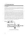
1.1 Overview
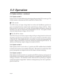
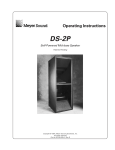
This equipment is a high performance line interactive uninterruptible power source
(UPS) designed to provide clean, reliable AC power to computer loads. The UPS's line
interactive circuit topology, illustrated below, offers excellent efficiency, on-line voltage
regulation and fast utility fault response.
The UPS’s DC-to-AC inverter is always connected to the output and when operating online, a portion of the inverter circuitry is put to work “in reverse” to continuously
maintain optimum float charge on the battery. The inverter circuitry also acts to protect
the load from surges and EMI/RFI noise as part of an advanced hybrid surge suppression and filtering network. A unique mode of operation, named SmartBoost, serves to
regulate the load voltage by compensating for brownouts or sags. This is accomplished
without the need to draw power from the UPS’s battery. In anticipation of utility failure,
the UPS continuously monitors the line and prepares the inverter frequency for
synchronous transfer of the load. Upon occurrence of utility voltage failure such as a
blackout, severe brownout or an overvoltage condition, the UPS transfers the load to
power derived from the battery. Transfer to the "on-battery" mode of operation takes
place typically within 2 milliseconds. The inverter's output voltage waveshape is a low
distortion sine wave. Resynchronization and retransfer to on-line operation is automatic upon recovery of the line voltage to within normal limits.
Line interactive UPS block diagram
Page2
1.0 Introduction
1.2 SmartBoost
SmartBoost allows continuous on-line operation during extended brownouts or low
line voltage conditions. The UPS compensates for the reduced line voltage by boosting
the load voltage to a value 12% above the input. Reliability is enhanced because the
limited battery capacity is saved for complete utility failures.
1.3 Battery replacement indicators and test
The UPS provides both visual and audible Replace Battery indications. The indications
are based on the result of an actual load test on the battery. By exercising the UPS’s
battery during a startup test, the UPS is able to detect a weak battery before it is put into
service. In applications where the UPS is not turned off daily, or where the UPS is
purposely left operating unattended, the UPS automatically conducts this self test
every 14 days.
1.4 Remote interfaces
The UPS provides a remote computer interface capable of full bidirectional RS-232
communications. When combined with PowerDoctor UPS monitoring software and a
serially connected local DOS PC, power quality related events can be logged. PowerChute plus offers all the features of PowerDoctor, plus the ability to control orderly and
unattended network or multi-user computer system shutdown during an extended
power outage. Also available for the UPS is the SNMP (Simple Network Management
Protocol) Adapter to provide load type independent remote monitoring and management across Ethernet or Token Ring based LANs or WANs capable of routing IP
messages. Using any standard Network Management System (NMS) and the SNMP
Adapter, the UPS becomes manageable through a single familiar interface - from across
your building to across the world.
1.5 Extended capabilities
Via the UPS's remote interface, the user can access advanced monitoring, power
management and operation customizing functions. Monitored parameters include
available run time, line voltage, line frequency, output power, output voltage, battery
capacity, battery voltage and internal temperature. Power management functions
include scheduled shutdown, power failure simulation, and remote turn off. UPS
functions that can be customized include the automatic self test and low battery
warning intervals; shut down, turn-off and turn-on delay intervals; transfer voltage;
utility fault sensitivity; and activation of the audible alarm.
Page3
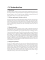
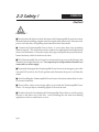
2.0 Safety !
ENGLISH
Caution!
CAUTION !
■ To reduce the risk of electric shock, disconnect the Uninterruptible Power Source from
the mains before installing computer interface signal cable (when used). Reconnect the
power cord only after all signalling interconnections have been made.
■ Connect the Uninterruptible Power Source to a two-pole, three-wire grounding
mains receptacle. The receptacle must be connected to appropriate branch protection
(fuse or circuit breaker). Connection to any other type of receptacle may result in a shock
hazard and may violate local electrical codes.
■ This Uninterruptible Power Source has an internal energy source (the battery) that
cannot be de-energized by the user. The output may be energized when the unit is not
connected to a mains supply.
■ To properly deenergize the Uninterruptible Power Source in an emergency, move the
rear panel I/O switch to the O (off) position and disconnect the power cord from the
mains.
■ Avoid installing the Uninterruptible Power Source in locations where there is water
or excessive humidity.
■ Do not allow water or any foreign object to get inside the Uninterruptible Power
Source. Do not put objects containing liquid on or near the unit.
■ To reduce the risk of overheating the Uninterruptible Power Source, avoid exposing
the unit to the direct rays of the sun. Avoid installing the unit near heat emitting
appliances such as a room heater or stove.
Page4
2.0 Sécurité !
FRANÇAIS
Attention!
ATTENTION!
■ Pour réduire le risque d’électrocution, débranchez la prise principale de la source
d’alimentation permanente (Uninterruptible Power Source), avant d’installer le câble
d’interface allant à l’ordinateur (si utilisé). Ne rebranchez le bloc d’alimentation
qu’après avoir effectué toutes les connections.
■ Branchez la source d’alimentation permanente (UPS) dans une prise de courant à 3
dérivations (deux pôles et la terre). Cette prise doit être munie d’une protection
adéquate (fusible ou coupe-circuit). Le branchement dans tout autre genre de prise
pourrait entraîner un risque d’électrocution et peut constituer une infraction à la
réglementation locale concernant les installations électriques.
■ Cette source d’alimentation permanente (UPS) est munie d’une source d’énergie
interne (accumulateur) qui ne peut pas être désactivée par l’utilisateur. La prise de
sortie peut donc être sous tension même lorsque l’appareil n’est pas branché.
■ En cas d’urgence, pour désactiver correctement la source d’alimentation permanente
(UPS), poussez l’interrupteur du panneau arrière sur la position O (Off) et débranchez
le cordon d’alimentation principal.
■ Ne pas installer la source d’alimentation permanente (UPS) dans un endroit où il y
a de l’eau ou une humidité excessive.
■ Ne pas laisser de l’eau ou tout objet pénétrer dans la source d’alimentation
permanente (UPS). Ne pas placer de récipients contenant un liquide sur cet appareil, ni
à proximité de celui-ci.
■ Pour éviter une surchauffe de la source d’alimentation permanente (UPS), conservezla à l’abri du soleil. Ne pas installer à proximité d’appareils dégageant de la chaleur tels
que radiateurs ou appareils de chauffage.
Page5
2.0 Sicherheit !
DEUTSCH
Vorsicht!
VORSICHT!
■ Um die Gefahr eines elektrischen Schlages auf ein Minimum zu reduzieren, die
unterbrechungsfreie Stromversorgung vom Stromnetz trennen, bevor ggf. ein Computer-Schnittstellensignalkabel angeschlossen wird. Das Netzkabel erst nach Herstellung
aller Signalverbindungen wieder einstecken.
■ Die unterbrechungsfreie Stromversorgung an eine geerdete zweipolige DreiphasenNetzsteckdose anschließen. Die Steckdose muß mit einem geeigneten Abzweigschutz
(Sicherung oder Leistungsschalter) verbunden sein. Der Anschluß der
unterbrechungsfreien Stromversorgung an einen anderen Steckdosentyp kann zu
Stromschlägen führen und gegen die örtlichen Vorschriften verstoßen.
■ Diese unterbrechungsfreie Stromversorgung besitzt eine interne Energiequelle
(Batterie), die vom Benutzer nicht abgeschaltet werden kann. Der Ausgang kann
eingeschaltet werden, wenn das Gerät nicht an das Stromnetz angeschlossen ist.
■ Um die unterbrechungsfreie Stromversorgung im Notfall ordnungsgemäß
abzuschalten, den I/O-Schalter an der Rückseite auf O (Aus) stellen und das Netzkabel
aus der Steckdose ziehen.
■ Die unterbrechungsfreie Stromversorgung nicht an einem Ort aufstellen, an dem sie
mit Wasser oder übermäßig hoher Luftfeuchtigkeit in Berührung kommen könnte.
■ Darauf achten, daß weder Wasser noch Fremdkörper in das Innere der
unterbrechungsfreien Stromversorgung eindringen. Keine Objekte, die Flüssigkeit
enthalten, auf oder neben die unterbrechungsfreie Stromversorgung stellen.
■ Um ein Überhitzen der unterbrechungsfreien Stromversorgung zu verhindern, das
Gerät vor direkter Sonneneinstrahlung fernhalten und nicht in der Nähe von
wärmeabstrahlenden Haushaltsgeräten (z.B. Heizgerät oder Herd) aufstellen.
Page6
2.0 ¡ Seguridad !
ESPAÑOL
¡Atencion!
¡ATENCION!
■ Para reducir el riesgo de descarga eléctrica, desconecte de la red la Fuente de energía
ininterrumpible antes de instalar el cable de señalización de interfaz de la computadora
(si se usa). Vuelva a conectar el conductor flexible de alimentación solamente una vez
efectuadas todas las interconexiones de señalización.
■ Conecte la Fuente de energía ininterrumpible a un tomacorriente bipolar y trifilar con
neutro de puesta a tierra. El tomacorriente debe estar conectado a la protección de
derivación apropiada (ya sea un fusible o un disyuntor). La conexión a cualquier otro
tipo de tomacorriente puede constituir peligro de descarga eléctrica y violar los códigos
eléctricos locales.
■ Esta Fuente de energía ininterrumpible tiene una fuente de energía interna (la batería)
que no puede ser desactivada por el usuario. La salida puede tener corriente aun
cuando la unidad no se encuentre conectada al suministro de red.
■ Para desactivar correctamente la Fuente de energía ininterrumpible en una situación
de emergencia, coloque el interruptor I/O del panel posterior en la posición O (Off desconectado) y desconecte de la red el conductor flexible de alimentación.
■ No instale la Fuente de energía ininterrumpible en lugares donde haya agua o
humedad excesiva.
■ No deje que en la Fuente de energía ininterrumpible entre agua ni ningún objeto
extraño. No ponga objetos con líquidos encima de la unidad ni cerca de ella.
■ Para reducir el riesgo de sobrecalentamiento, no exponga la unidad a los rayos
directos del sol ni la instale cerca de artefactos que emiten calor, como estufas o cocinas.
Page7
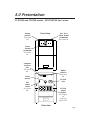
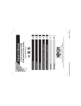
3.0 Presentation
3.1 900VA and 1250VA models - 100, 120 Vac versions
Display
features
See section
5.0.
Front view
On / Test /
Alarm disable
pushbutton
See section 5.1.
Power
standby
pushbutton
See section
5.1.
Computer
interface
port
See section
6.0.
Site wiring
fault light
See section
4.6.
Circuit
breaker
Option
switches
See section
5.6.
UPS
enable
switch
See section
4.4.
IEC 320
inlet
NEMA
5-15R
receptacles
Rear view
Page8
3.0 Presentation
3.2 900VA and 1250VA models - 220/230/240 Vac version
Display
features
See section
5.0.
Front view
On / Test /
Alarm disable
pushbutton
See section 5.1.
Power
standby
pushbutton
See section
5.1.
Computer
interface
port
See section
6.0.
Option
switches
See section
5.6.
Circuit
breaker
IEC 320
inlet
UPS
enable
switch
See section
4.4.
IEC 320
output
couplers
All couplers
are
protected
by the UPS.
Rear view
Page9
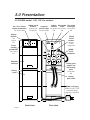
3.0 Presentation
3.3 2000VA model - 100, 120 Vac versions
On / Test / Alarm
disable pushbutton
See section 5.1.
15Amp circuit
Option UPS enable Site wiring
breaker
Computer
switches
switch
fault light
protects side interface port See section See section See section
receptacles
See section 6.0.
5.6.
4.4.
4.6.
Display
features
See
section
5.0.
15Amp
circuit
breaker
protects
center
receptacles
Power
standby
pushbutton
See section
5.1.
NEMA
5-15R
receptacles
Electronics
enclosure
Battery pack
coupler and
UPS locking
plate
See section
4.3.
Battery
pack
Battery
pack cables
NEMA 5-15P plug
NEMA L5-30P, 5-20P
rewireable plugs
supplied as alternate.
Front view
Page10
Rear view
3.0 Presentation
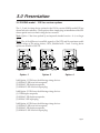
3.4 2000VA model - 120 Vac versions options
The -1, -2 and -4 wiring device options for the 120 Vac version 2000VA model UPS are
shown below for reference. These options allow simple plug-in installation of the UPS
where special service or load wiring devices are used.
Note: Option -3 has been replaced by an improved standard version - it is no longer
offered.
Note: Due to the difference in available capacity of the UPS and the maximum usable
current ratings of the wiring devices, UPSs furnished with -1 and -2 wiring device
options are derated to 1850 VA.
Option -1
Option -2
Option -4
3.4.1 Option -1 UPSs have the following wiring devices:
(1) NEMA L5-20R twist lock receptacle,
(2) NEMA 5-15R duplex receptacles,
(1) NEMA L5-20P twist lock input plug.
3.4.2 Option -2 UPSs have the following wiring devices:
(1) 5-20R duplex receptacle,
(2) NEMA 5-15R duplex receptacles,
(1) NEMA 5-20P input plug.
3.4.3 Option -4 UPSs have the following wiring devices:
(1) NEMA L5-30R twist lock receptacle,
(2) NEMA 5-15R duplex receptacles,
(1) NEMA L5-30P twist lock input plug.
Page11
3.0 Presentation
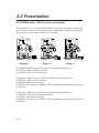
3.5 2000VA model - 208 Vac version and options
The standard 208 Vac version 2000VA model UPS and its wiring device options are
shown below for reference. These options allow simple plug-in installation of the UPS
where special service or load wiring devices are used.
Standard
Option -1
Option -2
3.5.1 Standard 208 Vac version UPSs have the following wiring devices:
(2) NEMA L6-30R twist lock receptacles,
(1) NEMA L6-30P twist lock input plug.
3.5.2 Option -1 208 Vac version UPSs have the following wiring devices:
(1) NEMA L6-20R twist lock receptacle,
(2) NEMA 6-20R duplex receptacles,
(1) NEMA 6-20P input plug - a NEMA L6-20P rewireable twist lock plug is provided as
an alternate.
3.5.3 Option -2 208 Vac version UPSs have the following wiring devices:
(1) NEMA L6-15R twist lock duplex receptacle,
(2) NEMA 6-15R duplex receptacles,
(1) NEMA 6-15P input plug - a NEMA L6-15P rewireable twist lock plug is provided as
an alternate.
Page12
3.0 Presentation
3.6 2000VA model - 220/230/240 Vac version
On / Test / Alarm UPS enable
switch
disable pushbutton
See section 4.4.
See section 5.1.
Computer
Option
interface port
switches
See section 6.0. See section 5.6.
Display
features
See
section
5.0.
15Amp
circuit
breaker
IEC 320
inlet
Power
standby
pushbutton
See section
5.1.
IEC 320
output
couplers
All couplers
are
protected by
the UPS.
Electronics
enclosure
Battery pack
coupler and
UPS locking
plate
See section
4.3.
Battery
pack
Battery
pack cables
Front view
Rear view
Page13
4.0 Installation
4.1 Receiving inspection
Once the UPS has been removed from its shipping container, it should be inspected for
damage that may have occurred while in transit. Immediately notify the carrier and
place of purchase if any damage is found. The packing materials are made from
recyclable materials and should be saved for reuse or disposed of properly.
4.2 Placement
The UPS may be installed in any protected environment. The location should provide
adequate air flow around the unit, in an atmosphere free from excessive dust.
Note: Allow 1" (2.5 cm)
minimum clearance on all
sides for proper ventilation.
Do not operate the UPS in an environment where the ambient temperature or humidity
is outside the limits given in the Specifications section of this manual.
Page14
4.0 Installation
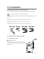
4.3 Connect battery pack - 2000VA model only
Follow the instructions listed below to install and lock the battery pack coupler.
Note: Use only factory supplied or authorized battery packs!
4.3.1 Use a phillips screwdriver to remove the battery coupler clamp from the electronics
enclosure.
4.3.2 Turn the battery coupler clamp and refasten loosely at one side.
4.3.3 Mate the battery pack coupler to the electronics enclosure.
4.3.4 Fasten remaining side of battery coupler clamp to lock in place.
4.4 Connect UPS to service and enable
4.4.1 Connect UPS to service
■ 100, 120 Vac versions
Plug the UPS into a two-pole, three wire grounding
receptacle only. Avoid the use of extension cords and
adapter plugs.
Page15
4.0 Installation
4.4 Connect UPS to service and enable - continued
■ 220/230/240 Vac versions
The 220/230/240 Vac version UPS is not furnished with an input line cord. Instead, two
output cords are supplied. However, in most installations it will not be necessary to
purchase a UPS input power cord. Simply swap the line cords from your equipment
with the furnished output cords. Plug in the UPS using one of the swapped out
equipment cords. The UPS's input cord must be three conductor, each 1.0 mm2, rated
to 10 Amps.
In the event your equipment does not have a removable line cord, the provided
rewireable plug may be installed on the line cord. Additional output cords and adapter
plugs are available from your dealer and from the factory.
The UPS may be configured to operate where 240 Vac, 50 Hz service is provided. When
Option switch 2 is set to the on position, the UPS's transfer and on-battery output
voltages are adjusted for proper operation on 240 Vac service. See section 5.6.
4.4.2 Enable UPS
Move the UPS Enable switch to the on ( I ) position. When
shipped, this switch is in the off position to prevent accidental
activation of the UPS. The batteries will not appreciably discharge if this switch is left on.
Allow the UPS to charge its battery for at least 8 hours before use. The UPS recharges
its battery whenever the utility voltage is normal and UPS Enable switch is ON. While
the UPS was shipped from the factory with the batteries in a fully charged state, the
batteries may lose some charge during shipping and storage. You may use the UPS
immediately without charging, but the Low Battery indicator may illuminate and the
UPS may have reduced backup time until the battery has had an opportunity to charge.
Page16
4.0 Installation
4.5 Plug loads into UPS
Plug all loads to be protected into the UPS. Do not exceed the UPS's capacity as given
in section 9.0. Once switched on, the UPS will monitor and display the magnitude of the
applied load.
Note: Do not plug laser printers into this UPS. Laser printers
draw a considerable amount of power. This will reduce the
available backup time and in some cases will cause the UPS to
signal an overload.
4.6 Check Site Wiring Fault indicator - 100, 120 Vac versions
Once loads are connected to the UPS and the UPS is turned on, the Site Wiring Fault
indicator at the UPS's rear panel should be checked. It will illuminate when the UPS is
plugged into an improperly wired wall outlet. Wiring faults detected include missing
ground, hot-neutral polarity reversal and overloaded neutral
circuit.
Note: If the UPS indicates a site wiring fault, a qualified electrician should be summoned to correct the building wiring.
4.7 Switch on load equipment
If load equipment switches are left on, the UPS'sI/Test pushbutton can be used as master
system on/off switch.
4.8 Switch on the UPS
The UPS and your loads will become energized when the I/Test
pushbutton is held pressed for a second. Once powered, the UPS
will initiate a battery test. During the test, the UPS will operate the
load from power derived from the battery. This test function ensures
that the UPS is working properly and that its battery does not require
replacement. In the event the batteries are too weak to support the load during
the test, the UPS will immediately return to on-line operation (the load will not be
affected). The test is completed when the On Line indicator ceases to blink.
Note: If the red Load indicator is illuminated, the UPS is overloaded. Unplug equipment
that does not require backing up, such as a printer, and restart the UPS. If the Replace
Battery indicator illuminates, recharge the UPS overnight and retest.
Page17
5.0 Operation
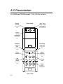
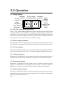
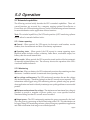
5.1 Display features
On Battery
On Line indicator
indicator
On, Test, Alarm
SmartBoost
disable pushbutton
indicator Replace
Battery
indicator
Power
bar graph
Power standby
pushbutton
Battery
capacity & line
voltage bar
graph
5.1.1 On / Test / Alarm disable pushbutton
The On / Test / Alarm disable pushbutton is used to control activation of the UPS and
to energize the load. Once the UPS is energized, pressing the button will initiate a
battery test. This will force the UPS to operate on-battery for a brief time during which
the UPS determines the strength of the battery. When the UPS is on-battery, this button
may be pressed to silence the utility failure audible warning.
5.1.2 Power standby pushbutton
When held pressed for a second, this control will deenergize the UPS and all protected
loads. However, operation of the UPS's battery charger is unaffected by this control.
5.1.3 On Line indicator
Illumination of the On Line indicator means that the load is being supplied conditioned
power derived from the utility service. The indicator blinks during the battery test.
5.1.4 On Battery indicator
Illumination of the On Battery indicator means that load has been transferred to power
derived from the UPS's battery and that utility voltage is not within normal limits.
5.1.5 Smart Boost indicator
Illumination of SmartBoost indicator means that the SmartBoost circuitry has been
engaged to compensate for unacceptably low line voltage. The UPS is capable of
operating in this mode continuously without draining charge from the battery.
5.1.6 Replace Battery indicator
Illumination of the Replace Battery indicator means that the automatic battery test has
found that the battery is weak and requires replacement. The indicator is extinguished
following a successful battery test.
Page18
5.0 Operation
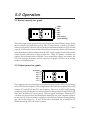
5.2 Battery capacity bar graph
100%
80%
60%
40%
20%
Low battery
when blinking
The battery capacity bar graph continuously displays the state of battery charge. In the
above example, the display shows that 100% of rated battery capacity is available.
Where power quality is fair, the UPS will be able to maintain the battery at 100% of rated
capacity. In the event of an extended utility failure, the capacity shown will decrease at
a rate dependent on the load drawn from the UPS. Large computer loads will cause the
battery capacity indication to fall at a faster rate. When low battery conditions are
reached, the bottom-most bar will blink. Once normal line voltages are restored, the
UPS will recharge the battery and the capacity bar graph will show an increasing
number of illuminated bars.
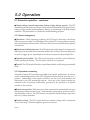
5.3 Output power bar graph
Overload
85%
67%
50%
33%
17%
The output power bar graph displays the power drawn from the UPS as a percentage
of the UPS's full rated capacity. This example shows that the load equipment is drawing
between 67% and 85% of the UPS's rated capacity. If this were a 1250VA UPS running
a computer load, then the above would correspond to between 840 VA and 1060 VA (590
Watts and 740 Watts at 0.7 power factor). This is a typical installation. When the UPS
is loaded such that five bars are illuminated, thoroughly test your complete system to
be sure the UPS will not become overloaded. A thorough test includes running backup
tape drives, disk drives, etc. If the UPS becomes overloaded, the overload bar will
illuminate and the UPS will sound an alarm.
Page19
5.0 Operation
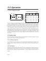
5.4 Line voltage bar graph
Bar increments versus version type
100 Vac
120 Vac
208 Vac
220/230/
240 Vac
116
130
237
260
109
123
225
246
102
116
212
232
96
110
200
220
90
104
187
208
84
98
175
196
The line voltage bar graph displays the UPS's input voltage in discrete steps. Line
voltage is displayed when the I/Test pushbutton is pressed and held. The example
above shows that the UPS's input line voltage is between 116 and 123 Vac (120 Vac
version UPS, see table for values for other versions). If no bars are illuminated, and the
UPS is plugged into a known working wall outlet, the line voltage is extremely low. Low
input voltage could be a result of an overloaded branch circuit, a misadjusted service
pole transformer or intentional local service brownout. The UPS will compensate for
this problem by boosting the load voltage supplied to your computer equipment. If all
six bars are illuminated, the line voltage is high and should be checked by a qualified
electrician.
5.5 Audible alarm
The UPS contains a beeper that emits sound through the ventilation openings. Events
that cause the beeper to sound are listed below.
5.5.1 On-battery operation
The UPS emits four short beeps every 30 seconds following failure of the utility. The
audible alarm is silenced until the next utility failure when the I/Test pushbutton is
pressed.
5.5.2 Low battery
During an extended utility failure, the UPS will eventually emit continuous beeps to
indicate that less than 2 minutes (or 5 minutes, see section 5.6) of run time remain before
shut down due to battery capacity exhaustion. The low battery warning cannot be
muted.
Page20
5.0 Operation
5.5.3 Replace battery
In the event the UPS's battery fails a battery test, the UPS will emit "chirps" for a period
of 1 minute. If the UPS is left operating while in this condition, the UPS will emits chirps
once every 5 hours until a successful battery test is completed.
5.5.4 Overload
The UPS will emit a loud, sustained tone when overloaded. When an overload is
applied while on-line, the alarm will sound until the overload is removed. If the
overload is applied while on-battery, the alarm will sound until the UPS Enable control
is switched off.
5.6 Option switches
Note: Option switches may
be thrown at any time and
take effect immediately.
5.6.1 Option switch 1
The UPS contains utility fault detection circuitry that is extremely sensitive to line
voltage distortions including spikes, notches, sudden dips and swells. The UPS is
factory set to react to such line voltage distortions by transferring the load immediately
to on-battery operation. This affords maximum protection for all load types. Where
power quality is poor due to local cyclic heavy load switching or use of inexpensive fuel
generators, the UPS may be caused to transfer to on-battery operation very often. If the
UPS is powering loads that are known to operate normally under such conditions, such
behavior is undesirable as battery capacity is being spent unnecessarily.
The user may set Option switch 1 to the on ( I ) position in order to desensitize the UPS
to rapid low amplitude line voltage fluctuations. When this is done, the UPS's upper
transfer voltage is also increased by 3%, for a total of 13% above the nominal input
voltage. This allows the UPS's battery charger to maintain maximum possible battery
capacity, saving it for gross utility failures.
Page21
5.0 Operation
5.6 Option switches - continued
5.6.2 Option switch 2
Option switch 2 controls different functions depending upon the UPS version type. The
switch controls no functions on 100 Vac and 208 Vac version UPSs.
■ 120 Vac version
The UPS's factory set input voltage limits for on-line and SmartBoost operation are
given in section 9.0 and are centered on the nominal input voltage of 120 Vac. When
Option switch 2 is set to the on ( I ) position, the upper and lower transfer voltages are
lowered by 4% and are centered on a nominal input of 115 Vac. This option is useful
where the nominal input voltage is 110 to 115 Vac.
■ 220/230/240 Vac version
The UPS's factory set on-battery output voltage and input voltage limits for on-line and
SmartBoost operation are appropriate for use in regions where the nominal line voltage
is 220 to 230 Vac. When Option switch 2 is set to the on ( I ) position, the upper and lower
transfer voltages are raised by 4% and are centered on a nominal input of 240 Vac. In
addition, the on-battery output voltage is increased to 240 Vac.
5.6.3 Option switch 3
When Option switch 3 is set to the on ( I ) position, the UPS's audible alarm is disabled
for the first 30 seconds of an extended utility fault. This function is useful where brief
power interruptions are frequent and cause the alarm to become annoying.
5.6.4 Option switch 4
When Option switch 4 is set to the on ( I ) position, the UPS's low battery warning interval
before shutdown due to battery capacity exhaustion is extended from 2 minutes (factory
setting) to 5 minutes. This function is useful where the UPS is protecting a computer
system that requires longer than 2 minutes warning before power loss to perform a
graceful shutdown.
Page22
5.0 Operation
5.7 Extended capabilities
The following sections briefly describe the UPS’s extended capabilities. These advanced functions are accessed by a computer running optional PowerDoctor or
PowerChute plus UPS monitoring software. See the UPS monitoring software literature
for more information on the application of these functions.
Note: The extended capabilities of the UPS and operation of UPS monitoring software
may be altered or amended without notice.
5.7.1 Status reporting
● General - When queried, the UPS reports its electronics serial number, version
number, date of manufacture and date of last battery replacement.
● Operating status - When queried, the UPS reports its current operating status.
Reported modes includes on-line, on-battery, Smart Boost, overloaded output, low
battery, shut down and internal fault.
● Test results - When queried, the UPS reports the stored results of the last automatic
or manually initiated battery test. The user may also test the operation of the UPS’s
visual and audible indicators.
5.7.2 Monitoring
● Run time - When on-battery, the UPS continuously monitors the remaining run time
in minutes. Available run time is monitored when operating on-line.
● Line voltage and frequency- The UPS continuously monitors the rms line voltage
and the line frequency. Transients lasting less than 0.5 seconds are not reported. This
information can be logged using UPS monitoring software, plotted using any spreadsheet application and used to identify transient power quality problems over extended
periods.
● Minimum and maximum line voltage - The minimum and maximum line voltage is
recorded to provide a snapshot of power quality over a user specified interval.
Transients lasting less than 0.5 seconds are not recorded.
● Output power - The UPS continuously monitors the power consumed by the load.
The value given is a percentage of the full load rating of the UPS. This information can
be logged using UPS monitoring software, plotted using any spreadsheet application
and used to determine load usage over extended periods.
Page23
5.0 Operation
5.7 Extended capabilities - continued
● Output voltage, internal temperature, battery voltage, battery capacity - The UPS
continuously monitors the rms output voltage, internal temperature in degrees Celsius,
battery voltage, and the remaining battery capacity as a percentage of the fully charged
condition. This information is valuable for troubleshooting purposes.
5.7.3 Power management
● Shut down - While operating on-battery, the UPS may be directed to shut down
following a user set delay. Controlled shut down of the UPS conserves battery capacity
and extends battery life because the UPS is not allowed to run until all battery capacity
is exhausted.
● Shut down with delayed restart - The UPS may be directed to shut down in any mode
following a user set delay, then restart after another user set delay. The restart delay may
be used to stagger power up multiple network servers protected by multiple UPSs.
● Simulate power failure - The UPS may be directed to simulate a power failure by
briefly operating on-battery. This function is useful for test purposes.
● Turn off - The UPS may be directed to turn off immediately or following a user settable
delay.
5.7.4 Operation customizing
Alteration of many UPS operations is possible to suit specific applications. In order to
use the customizing features of the UPS, all Option switches must be set to the on ( I )
position. Functionality of the option switches is not lost as all such functions are
duplicated by the UPS monitoring software. Once any of the Option switches are
returned to the off position, functionality governed by the position of all Option
switches is also restored.
● Battery test operation - The battery test can be customized to automatically run upon
startup, upon startup and once every 7 days thereafter, upon startup and once every 14
days thereafter, or never. The UPS’s battery test operation default setting is upon start
and every 14 days thereafter.
● Transfer voltage - The UPS’s upper and lower transfer voltages can be customized
over a wide range. Default settings are given in section 9.0.
Page24
5.0 Operation
5.7 Extended capabilities - continued
● On-battery output voltage (220/230/240 Vac versions only) - The UPS’s on-battery
output voltage may be set to a nominal 220, 225, 230 or 240 Vac. The UPS’s default setting
is 225 Vac.
● Utility failure sensitivity - The UPS’s sensitivity to line voltage distortions may be
customized to allow use of the UPS in “noisy” electrical environments or with fuel
powered generators. High, medium and low sensitivity settings may be chosen. The
high setting provides the best protection from all utility voltage vagaries. The medium
setting is selected where rapid low amplitude line voltage fluctuations occur frequently
as the result of motor load switching in air conditioners, elevators, etc. The low setting
is selected when the UPS is operated from an inexpensive fuel powered generator. The
UPS’s utility failure sensitivity default setting is high.
● Low battery warning interval - The UPS’s low battery warning may be customized
to activate at a time 2, 5, 7 or 10 minutes prior to shut down. The UPS’s low battery
warning interval default setting is 2 minutes.
● Audible alarm operation - The UPS’s audible alarm beeps four times every 30
seconds in response to failed utility conditions. The alarm beeps continuously when
low battery conditions are reached. This is the default operation. Audible alarm
operation may be customized such that an indication in response to utility failure is
delayed by 30 seconds, silenced until low battery conditions are reached, or muted
during both utility failure and low battery conditions.
● Minimum battery capacity to restart - The UPS may be customized so that it will not
restart upon restoration of the utility until the battery has been recharged to within 0%,
10%, 25% or 90% of full capacity. This function eliminates unexpectedly short run times
when repetitive utility failures occur. The UPS’s minimum battery capacity to restart
default setting is 0%.
● Shut down, turn off delay - The UPS’s shut down or turn off delay interval may be
customized to 20, 180, 300 or 600 seconds. The UPS’s shut down delay default setting
is 20 seconds. Extension of the shut delay is useful where the time between issuance of
the UPS shut down command, and actual completion of the operating system shutdown routine is longer than 20 seconds.
● Turn on delay - The UPS’s turn on delay may be customized to 0, 60, 180 or 300
seconds. The UPS’s turn on delay default setting is 0 seconds.
Page25
6.0 UPS Monitoring
6.1 Overview
A UPS system alone provides excellent protection from brief power problems. However, during an extended power outage an unattended computer system will eventually
shut down due to battery capacity exhaustion. To prevent data corruption when the
UPS shuts down, the computer must be informed by the UPS of impending shut down
and take appropriate file-saving measures. This important function is called “UPS
monitoring.” The UPS’s computer interface port is the means by which your UPS
communicates with a computer system.
Some computer operating systems have built-in UPS monitoring. These systems
require various hardware interfaces. Interface kits for all operating systems that
support UPS monitoring are available from your dealer. In addition, your dealer also
offers PowerChute software which enhances such built-in UPS monitoring. Versions of
PowerChute are available which add the UPS monitoring function to the many
operating systems which do not inherently provide UPS monitoring.
6.2 Interface Kits
A series of interface kits is available for operating systems that provide UPS monitoring.
Each interface kit includes the special interface cable required to convert status signals
from the UPS into signals which individual operating systems recognize. Each kit
includes all necessary installation instructions. Systems for which interface kits are
offered include Novell, LAN Manager, LAN Server, LANtastic, Banyan VINES and IBM
AS/400.
6.3 PowerChute Software
PowerChute software provides complete data protection for most operating systems.
This software is a background process that monitors the UPS through a RS-232 serial
port on the host. PowerChute offers user notification of impending shutdown, power
event logging, auto-restart upon power return and UPS battery conservation features.
For selected operating systems, PowerChute offers sophisticated power diagnostic and
network power management features. These include interactive battery testing;
scheduled server shutdowns, reboots and battery testing; detailed power quality
logging and a remote, real time, graphical power status display showing UPS loading
and battery conditions. PowerChute is available for many platforms including Novell,
OS/2,AppleShare, XENIX, most UNIX-based operating systems, and DEC VAX/VMS.
Caution: Use only factory supplied or authorized UPS monitoring cables!
Page26
6.0 UPS Monitoring
6.4 Computer interface port
The computer interface port is diagramed below for your reference. Those with
technical abilities wishing to use this port in a special application should be aware of the
following limitations and capabilities of the interface.
■ Outputs at pins 3, 5 and 6 are actually open collector outputs which must be pulled
up to a common referenced supply no greater than +40 Vdc. The transistors are capable
of a maximum non-inductive load of 25 mAdc. Use only Pin 4 as the common.
■ The output at Pin 2 will generate a LO to HI RS-232 level upon transfer of the output
load to power derived from the UPS’s battery. The pin is normally at a LO RS-232 level.
■ The UPS will shut down when a HI RS-232 level, sustained for 4.5 s, is applied to Pin
1. The UPS responds to this signal, following a delay, only during mains failures (load
is operating from the UPS’s internal power source).
■ An unregulated +24 Vdc appears at Pin 8 of the interface port whenever the UPS is
powered. The supply is limited to 40 mAdc maximum.
Page27
7.0 Difficulty
ENGLISH
Caution !
CAUTION !
■ This Uninterruptible Power Source contains potentially hazardous voltages. Do not
attempt to disassemble the unit. The unit contains no user serviceable parts. Repairs
are performed only by factory trained service personnel.
■ This Uninterruptible Power Source uses batteries. The batteries will eventually
become too weak to provide rated autonomous operation. Due to the potential health
and environmental hazards posed by the batteries, they may be replaced only at factory
authorized Service Centers. To obtain battery replacement or repair service, please call
the Customer Service telephone number written on the cover of this manual for
information on the Service Center nearest you.
■ The batteries used by this Uninterruptible Power Source are recyclable. Proper
disposal of the batteries is required. The batteries contain lead and pose a hazard to
the environment and human health if not disposed of properly. Please refer to local
codes for proper disposal requirements or return the unit to a factory authorized
Service Center for battery replacement or disposal.
■ Battery replacement should be performed or supervised by personnel familiar with
the danger of batteries and the required precautions. Keep unauthorized personnel
away from batteries. When replacing batteries, use the same number and type of sealed
lead acid batteries as were originally contained in your UPS.
■ CAUTION - Do not dispose of batteries in a fire. The batteries may explode.
■ CAUTION - Do not open or mutilate batteries. They contain an electrolyte which is
toxic and harmful to the skin and eyes.
■ CAUTION - A battery can present a risk of electrical shock and high short circuit
current. When replacing batteries, wrist watches and jewelry such as rings should be
removed. Use tools with insulated handles.
Page28
7.0 Difficulté
FRANÇAIS
Attention !
ATTENTION!
■ Cette source d’alimentation permanente (UPS) contient des circuits haute tension
présentant un danger. Ne jamais essayer de le démonter. Il n’y a aucun composant qui
puisse être réparé par l’utilisateur. Toutes les réparations doivent être effectuées par du
personnel qualifié et agréé par le constructeur.
■ Cette source d’alimentation permanente (UPS) contient des accumulateurs. Ces
accumulateurs deviendront un jour trop faibles pour pouvoir assurer un fonctionnement
autonome correct. En raison des risques que posent les accumulateurs à la santé et à
l’environnement, ils ne peuvent être remplacés que dans les Centres de Service agréés
par le fabriquant. Pour toute réparation ou remplacement des accumulateurs, composez
le numéro du Service à la clientèle inscrit sur la couverture de ce manuel afin d’obtenir
les coordonnées du Centre de Service le plus proche.
■ Les accumulateurs contenus dans cette source d’alimentation sont recyclables.
L’elimination des batteries est règlementée. Consulter les codes locaux à cet effet. Ils
contiennent du plomb et représentent donc un risque pour l’homme et pour
l’environnement si les règles de mise au rebut ne sont pas respectées. Veuillez
retournez l’unité à un Centre de Service agréé lorsque vous désirerez remplacer ou
vous débarrasser des accumulateurs usagés.
■ ATTENTION - Pour le remplacement, utiliser le même nombre de batteries du
modéle suivant: accumulateur au plomb.
■ ATTENTION - Une batterie peut présenter un risque de choc electrique, de brûlure
par transfert d’énergie. Suivre les précautions qui s’imposent.
Page29
7.0 Schwierigkeit
DEUTSCH
Vorsicht !
VORSICHT!
■ Im Inneren dieser unterbrechungsfreien Stromversorgung herrschen potentiell
gefährliche Spannungen. Nicht versuchen, das Gerät zu öffnen. Es enthält keine vom
Benutzer reparierbaren Teile. Reparaturen dürfen nur von ausgebildetem
Kundendienstpersonal durchgeführt werden.
■ Diese unterbrechungsfreie Stromversorgung enthält Batterien, die nach einer
bestimmten Zeit so schwach werden, daß der autonome Nennbetrieb nicht mehr
gewährleistet ist. Aufgrund der potentiellen Gesundheits- und Umweltgefahren, die
von den Batterien ausgehen, dürfen sie nur in einem vom Werk autorisierten
Kundendienstzentrum ausgewechselt werden. Wenn die Batterien ausgewechselt
werden müssen oder Reparaturen fällig sind, die auf der Umschlagseite dieser
Gebrauchsanweisung angegebene Kundendienst-Telefonnummer anrufen. Dort teilt
man Ihnen mit, welches Kundendienstzentrum für Sie zuständig ist.
■ Die Batterien in dieser unterbrechungsfreien Stromversorgung sind
wiederverwertbar. Sie sind bleihaltig und stellen eine Gefahr für die Umwelt und
die Gesundheit dar, wenn sie nicht ordnungsgemäß entsorgt werden. Das Gerät an
ein vom Werk autorisiertes Kundendienstzentrum einsenden, um die Batterien
auswechseln oder entsorgen zu lassen.
Page30
7.0 Dificultad
ESPAÑOL
¡Cuidado!
¡CUIDADO!
■ Esta Fuente de energía ininterrumpible contiene niveles de voltaje peligrosos en
potencia. No intente desarmar la unidad, pues no contiene piezas que puedan ser
reparadas por el usuario. Las reparaciones deben efectuarse únicamente por parte del
personal de mantenimiento capacitado en la fábrica.
■ Esta Fuente de energía ininterrumpible contiene baterías. Con el tiempo las baterías
se gastan demasiado para poder sustentar el funcionamiento autónomo a la capacidad
nominal. Debido a que presentan un peligro potencial para la salud y el medio ambiente,
las baterías pueden reemplazarse únicamente en los Centros de Servicio autorizados
por la fábrica. Para solicitar el reemplazo de baterías o servicio de reparaciones, se ruega
llamar al número telefónico deAtención a los Clientes indicado en la tapa de este manual
y averiguar el Centro de Servicio más cercano.
■ Las baterías que se encuentran en esta Fuente de energía ininterrumpible son
reciclables. Las baterías contienen plomo y constituyen un peligro para el medio
ambiente y para la salud de las personas si no se las desechan como corresponde. Se
ruega devolver la unidad a un Centro de Servicio autorizado por la fábrica para el
reemplazo o la eliminación de las baterías.
Page31
7.0 Difficulty
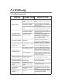
7.1 Troubleshooting chart
PROBLEM
POSSIBLE CAUSE
ACTION TO TAKE
1. UPS Enable switch is in the off 1. Turn on the rear panel UPS Enable switch.
position or front panel switch not Press front panel switch to power UPS and
pressed.
loads.
UPS will not turn on.
2. UPS’s input circuit breaker is
tripped (button is extended).
2. Reduce the UPS’s load by unplugging
equipment and reset the circuit breaker (press
button on rear panel).
3. Very low utility voltage or dead 3. Check outlet with a table lamp. If very dim,
outlet.
have utility voltage checked by an electrician.
1. UPS’s input circuit breaker is
tripped (button is extended).
1. Reduce the UPS’s load by unplugging
equipment and reset the circuit breaker (press
button on rear panel).
UPS operates on-battery
even though normal line
voltage is thought to exist.
2. Very high, low or badly
distorted line voltage.
2. Test the input voltage with UPS’s Line
voltage bar graph - see section 5.0.
Inexpensive fuel powered generators can
cause distorted line voltages - set Option
switch 1 to the on ( I ) position.
UPS "beeps" occasionally.
This is normal.
UPS beeps more than once
or twice an hour.
Chronically high or distorted line
voltage.
UPS does not provide
expected back up time.
Set Option switches 1 and 2 to match input
voltage range. Alternatively, set Option switch
3 to the on ( I ) position - see section 5.0.
1. UPS’s battery is weak due to
recent utility outage or wear.
1. The UPS’s batteries require recharging
following an extended outage. The batteries
will wear faster when put into service often
and when operating at elevated temperatures.
2. UPS is overloaded.
2. Check load using UPS’s Output power bar
graph - see section 5.0. Unplug non-critical
equipment such as printers.
Indicators on front panel flash UPS has been shut down by
in a "marquee" fashion.
computer software.
All indicators are illuminated
Internal UPS fault.
and UPS emits constant tone.
Site wiring fault light is
illuminated - UPS operates
normally.
The UPS is protecting your computer
equipment from momentary sags or swells.
Building wiring error such as
missing ground or hot-neutral
reversal.
UPS will restart when AC power returns.
Do not attempt to use UPS. Turn off UPS and
have it serviced immediately.
A qualified electrician should be summoned to
correct the building wiring.
Low battery light is illuminated UPS is shut down and battery is
and on-line light is
discharged due to extended
extinguished.
power failure.
UPS will return to normal operation when
power is restored and battery has charged
sufficiently.
Replace battery light is
illuminated.
Allow the batteries to recharge for at least 8
hours. If the problem persists after recharging,
the batteries should be replaced.
Page32
Weak battery.
7.0 Difficulty
7.2 Battery replacement check
You can expect to receive 3 to 6 years of service life from the UPS's batteries when
installed in a cool, dry location. Battery life is shortened when operated in an
environment where the ambient temperature is normally above 30°C (86°F).
The UPS automatically performs a battery test upon start up and, if left operating, every
14 days thereafter. This test actually loads the battery for a brief time and will detect a
weak battery before it is put into service during a power failure. If the battery is too weak
to support the load during this test, the UPS will instantly return to on-line operation.
The UPS will illuminate the Replace Battery indicator when it is detected that the
batteries can no longer sustain sufficient charge. This means that the UPS would be
unable to provide power for longer than half the normal interval (see section 9.9) during
an extended utility failure.
If the UPS illuminates the Replace Battery indicator, perform the following procedures
to be sure that the batteries need replacing.
7.2.1 Use the UPS's Line voltage bar graph to check that the utility voltage is within a
normal range. The UPS will charge the batteries at a slower rate when operated from
very low input voltages. Where low line voltages and frequent disturbances are
common, set the UPS's Option switch 1 to the on ( I ) position - see section 5.0.
7.2.2 Allow the UPS to charge the batteries for at least 8 hours following an extended
utility failure.
7.2.3 Recheck the UPS's batteries by conducting a battery test. Press the I/Test button
to initiate the battery test.
7.2.4 If the Replace Battery indicator does not illuminate following the battery test, the
batteries do not require replacement. Extended storage without recharge, or successive
power outages can cause false indications.
7.2.5 If the Replace Battery is illuminated following the battery test, the batteries are
worn and need to be replaced.
7.2.6 Call the Customer Service phone number given on the cover of this manual to
obtain information about battery replacement service or battery replacement kits.
Note: Please see the battery cautions at the beginning of this section.
Page33
7.0 Difficulty
7.3 Obtaining Service
The troubleshooting chart in section 7.1 covers most of the difficulties that a user may
encounter under conditions other than a failure of the UPS itself. For problems not
covered in the chart, the procedures outlined below should be followed.
If your UPS should require service:
■ See the troubleshooting chart and eliminate the obvious. A tripped UPS circuit
breaker is the most common problem encountered and is user resettable once
excessive loads are unplugged from the UPS.
■ If the circuit breaker is OK, note your UPS model, serial number and date of purchase.
Contact the Customer Service Department at the phone number given on the cover of
this booklet.
■ Be prepared to provide a description of the problem. A technician will help you solve
the problem over the phone if possible, or will give you a Return MaterialAuthorization
Number (RMA#).
■ If the UPS is within the warranty period, repairs will be performed free of charge. If
it is not within the warranty period, there will be a charge for repair.
■ Pack the UPS in its original packaging. If you no longer have the original shipping
materials, ask the technician about obtaining a new set. It is very important that you pack
the UPS properly to avoid damage in transit. Never use styrofoam beads for packaging
the UPS because it will settle through beads and become damaged. Damages sustained
in transit are not covered under warranty. Enclose a letter in the package with your
name, RMA#, address, copy of sales receipt, description of trouble, phone number and
check (if necessary).
■ Mark your RMA# on the outside of the package. The factory cannot accept any package
without this marking.
■ Return your UPS via insured, prepaid carrier to the address on the rear of this booklet.
Page34
8.0 Storing the UPS
8.1 Storage conditions
The UPS should be covered and stored upright in a cool dry location. The UPS should
be stored with its battery in a fully charged state. That is, the indicated battery capacity
should be 100% before the UPS is switched off for storage. Disconnect accessories or
cables connected at the computer interface port as such devices may unnecessarily
drain battery charge.
8.2 Extended storage
To achieve expected run time following extended storage, the UPS should be allowed
to refresh its batteries every 6 months in environments where the ambient temperature
is -15°C to +30°C (5°F to 86°F). For extended storage in environments where the ambient
temperature is +30°C to +45°C (86°F to 113°F), the UPS should be allowed to refresh its
batteries every 3 months.
Page35
9.0 Specifications
Note: Where specifications ratings differ, values for the 100 Vac version are given in { } brackets,
values for 208 Vac versions are given in ( ) brackets, and values for 220/230/240 Vac versions
are given in [ ] brackets.
9.1 Input
Nominal input voltage: single phase, {100 Vac}, 120 Vac, (208 Vac), [220/230/240 Vac].
Nominal input frequency: 50 or 60 Hz, internally selected by microprocessor.
Input protection, 900VA model: {14Amp}, 14 Amp, [12 Amp] resettable circuit breaker.
Input protection, 1250VA model:{15Amp}, 14Amp, [12Amp] resettable circuit breaker.
Input protection, 2000VA model: (14 Amp), [15 Amp] resettable circuit breaker.
9.2 Transfer characteristics
Frequency limits for on-line operation: 50 or 60 Hz, ±5%.
Lower input voltage limit for on-line operation: {80 Vac}, 90 Vac, (150 Vac ), [173 Vac;
when set for operation at the nominal 240 Vac line, the lower input voltage limit is
increased to 180 Vac].
Upper input voltage limit for on-line operation: {110 Vac}, 132 Vac, (224 Vac), [253 Vac;
when set for operation at the nominal 240 Vac line, the upper input voltage limit is
increased to 264 Vac].
SmartBoost operation input voltage range: {80 to 90 Vac}, 90 to 103 Vac, (150 to 172 Vac),
[173 to 196 Vac; when set for operation at the nominal 240 Vac line, the SmartBoost input
voltage range is increased to 180 to 204 Vac].
Transfer time: 2 ms typical, 4 ms maximum. Note that 1 ms is 0.001 seconds.
9.3 Output characteristics
Maximum load, 900VA model: 900 VA or 630 W @ 0.70 power factor.
Maximum load, 1250VA model: 1250 VA or 900 W @ 0.72 power factor.
Maximum load, 2000VA model - 100, 120 Vac versions: 2000 VA or 1500 W @ 0.75 power
factor with supplied NEMA L5-30P installed; 1850 VA or 1500 W @ 0.81 power factor
with supplied NEMA 5-20P installed; 1440 VA or 1440 W as supplied. See section 3.0
for maximum load ratings of models with wiring device options.
Maximum load, 2000VA model - 208, 220/230/240 Vac versions: 2000 VA or 1500 W @
0.75 power factor.
On-battery output voltage: {100 Vac}, 115 Vac, (208 Vac), [225 Vac] ±5%. The 220/230/
240 Vac version may be set to provide a nominal 240 Vac, see section 5.0.
On-battery frequency: 50 or 60 Hz, ±0.1 Hz unless synchronized to mains frequency
during utility brownout.
On-battery waveshape: low distortion sinewave.
Protection: overcurrent and short circuit protected, latching shutdown upon overload.
Page36
9.0 Specifications
9.4 Noise and surge suppression
Surge energy rating (one time, 10/1000 µs waveform): {160 J}, 480 J, (480 J), [480 J].
Surge current capability (one time, 8/20 µs waveform): 6500 Amp peak maximum.
Surge response time: 0 ns (instantaneous) normal mode, <5 ns common mode.
Surge voltage let-through: {<0.3%], <0.3%, (<2%), [<2%] of applied ANSI C62.41
Category A ± 6 kV test waveform.
Noise filter: normal and common mode EMI/RFI suppression, 100 kHz to 10 MHz.
9.5 Battery and charger
Battery type: spill proof, maintenance free sealed lead-calcium.
Typical battery life: 3 to 6 years - depends on number of discharge cycles and ambient
temperature.
Typical recharge time: 4 to 10 hours from total discharge. UPS may be used
immediately after discharge but will provide shorter run time.
9.6 Environment
Operating temperature: 0°C to 40°C (32°F to 104°F).
Storage temperature: -15°C to 45°C (5°F to 113°F).
Operating and storage relative humidity: 0 to 95%, non-condensing.
Operating elevation: 0 to 3,000 m (10,000 ft).
Storage elevation: 0 to 15,000 m (50,000 ft).
Electromagnetic immunity: IEC 801-2, 801-3, 801-4, 801-5; severity levels III or IV.
Audible noise, 900VA model: < 45 dBA at 1 m (3 ft).
Audible noise; 1250VA, 2000VA models: < 50 dBA at 1 m (3 ft).
9.7 Physical
Size; 900VA, 1250VA models: 9.1"H x 6.9"W x 17.8"D (23.1 x 17.5 x 45.2 cm).
Size, 2000VA model: two enclosures each 9.1"H x 6.9"W x 17.8"D (23.1 x 17.5 x 45.2 cm).
Weight, 900VA model: 43 lbs (19.5 kg), shipping weight is 48 lbs (21.8 kg).
Weight, 1250VA model: 50 lbs (22.7 kg), shipping weight is 55 lbs (24.9 kg).
Weight, 2000VA model: Electronics enclosure is 39 lbs (17.7 kg), shipping weight is 44
lbs (20.0 kg). The battery is 61 lbs (27.7 kg), shipping weight is 66 lbs (29.9 kg).
9.8 Approvals
Safety approvals: UL per 1778, CSA per C22.2, TUV per IEC 950.
EMC verification: FCC, DOC Class A and B verified; VCCI Class 2 compliance;
EN55022 Class B verified.
Page37
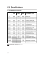
9.0 Specifications
9.9 Typical run time versus load
Load
900VA
model
1250VA
model
2000VA
model
Typical computer load
(0.7 volt-amps = Watts)
50 VA
150 min
290 min
450 min
Typical ASCII terminal
75 VA
125 min
250 min
400 min
Macintosh SE/30
100 VA
100 min
210 min
350 min
IBM PS/2 30 w/ monochrome monitor
150 VA
75 min
160 min
280 min
IBM PS/2 30 with VGA monitor
200 VA
58 min
120 min
220 min
IBM PS/2 55sx with VGA monitor
250 VA
44 min
90 min
180 min
Compaq 386/25e with VGA monitor
300 VA
36 min
70 min
145 min
Compaq 386/33 with VGA monitor
350 VA
28 min
50 min
109 min
IBM PS/2 80 file server
400 VA
24 min
38 min
88 min
Compaq 386/33 with 19" monitor
450 VA
20 min
32 min
70 min
Compaq 486/33 with 19" monitor
500 VA
18 min
27 min
55 min
Compaq Systempro server
550 VA
15 min
24 min
45 min
(2) Compaq 386/25e w/ VGA monitors
600 VA
13 min
22 min
40 min
(2) Compaq 386/33 with VGA monitors
700 VA
11 min
17 min
35 min
(2) IBM PS/2 80 file servers
800 VA
9 min
14 min
29 min
IBM AS/400 B20 minicomputer
900 VA
7 min
12 min
25 min
DEC MicroVax
1000 VA
10 min
22 min
(2) Compaq Systempro servers
1200 VA
7 min
17 min
(4) Compaq 386/33 w/ VGA monitors
1400 VA
14 min
1600 VA
11 min
(8) IBM PS/2 55sx w/ VGA monitors
2000 VA
8 min
(4) Compaq Systempro servers
Note: Run times are typical at 25°C (77°F).
Page38
Notes
Page39
DECLARATION OF CONFORMITY
Application of Council Directive(s):
89/336/EEC
Standard(s) to which Conformity is Declared:
EN55022, EN50082-1
Manufacturer's Name:
AMERICAN POWER CONVERSION
Manufacturer's Address:
132 FAIRGROUNDS ROAD
WEST KINGSTON, RI
02892
USA
Importer's Name:
Importer's Address:
Type of Equipment:
UNINTERRUPTIBLE POWER SOURCE
Model No.: SMART-UPS 900, 1250, 2000, 2000M INCLUDING
OPTIONS -1, -2, -3, -4
Serial Number:
S930100001-S931299999, S940100001-S941299999
Year of Manufacture:
1993, 1994
I, the undersigned, hereby declare that the equipment specified above conforms
to the above Directives(s).
Place: BILLERICA, MA
USA
(Signature)
Date:
11/1/93
Joseph Pomata
(Full name)
Regulatory Compliance Engineer
(Position)
Page40
Limited Warranty
American Power Conversion (APC) warrants its products to be free from defects in materials
and workmanship for a period of two years from the date of purchase. Its obligation under this
warranty is limited to repairing or replacing, at its own sole option, any such defective
products. To obtain service under warranty you must obtain a Returned Material Authorization (RMA) number from APC or an APC service center. Products must be returned to APC
or an APC service center with transportation charges prepaid and must be accompanied by a
brief description of the problem encountered and proof of date and place of purchase. This
warranty does not apply to equipment which has been damaged by accident, negligence, or
mis-application or has been altered or modified in any way. This warranty applies only to the
original purchaser who must have properly registered the product within 10 days of purchase.
EXCEPT AS PROVIDED HEREIN, AMERICAN POWER CONVERSION MAKES NO WARRANTIES, EXPRESS OR IMPLIED, INCLUDING WARRANTIES OF MERCHANTABILITY
AND FITNESS FOR A PARTICULAR PURPOSE. Some states do not permit limitation or
exclusion of implied warranties; therefore, the aforesaid limitation(s) or exclusion(s) may not
apply to the purchaser.
EXCEPT AS PROVIDED ABOVE, IN NO EVENT WILL APC BE LIABLE FOR DIRECT,
INDIRECT, SPECIAL, INCIDENTAL, OR CONSEQUENTIAL DAMAGES ARISING OUT OF
THE USE OF THIS PRODUCT, EVEN IF ADVISED OF THE POSSIBILITY OF SUCH DAMAGE. Specifically, APC is not liable for any costs, such as lost profits or revenue, loss of
equipment, loss of use of equipment, loss of software, loss of data, costs of substitutes, claims
by third parties, or otherwise. This warranty gives you specific legal rights and you may also
have other rights which vary from state to state.
Life support policy
As a general policy, American Power Conversion (APC) does not recommend the use of any
of its products in life support applications where failure or malfunction of the APC product can
be reasonably expected to cause failure of the life support device or to significantly affect its
safety or effectiveness. APC does not recommend the use of any of its products in direct patient
care. APC will not knowingly sell its products for use in such applications unless it receives in
writing assurances satisfactory to APC that (a) the risks of injury or damage have been
minimized, (b) the customer assumes all such risks, and (c) the liability of American Power
Conversion is adequately protected under the circumstances.
Examples of devices considered to be life support devices are neonatal oxygen analyzers, nerve
stimulators (whether used for anesthesia, pain relief, or other purposes), autotransfusion
devices, blood pumps, defibrillators, arrhythmia detectors and alarms, pacemakers,
hemodialysis systems, peritoneal dialysis systems, neonatal ventilator incubators, ventilators
for both adults and infants, anesthesia ventilators, and infusion pumps as well as any other
devices designated as “critical” by the U.S. FDA.
Hospital grade wiring devices and leakage current may be ordered as options on many APC
UPS systems. APC does not claim that units with this modification are certified or listed as
Hospital Grade by APC or any other organization. Therefore these units do not meet the
requirements for use in direct patient care.
TM
( PHONE
( PHONE
(800) 800-4272 in USA, Canada
(401) 789-5735 world wide
(+33) 1.64.62.59.00 in Eur
ope
Europe
(401) 789-5735 world wide
* MAILING
* MAILING
American Power Conversion
132 Fairgrounds Road
P.O. Box 278
West Kingston, Rhode Island
02892 USA
American Power Conversion
4, rue Ste Claire Deville
Zac du Mandinet-Bâtiment Espace
LOGNES
77447 MARNE LA VALLEE Cédex 2
FRANCE
Note: The troubleshooting chart in section 7.0 offers solutions for most of the difficulties
you may encounter with this UPS. Before calling the customer service number,
please have available your UPS's serial number (see the label at the rear of the
UPS).
Serial number: ___________________________
Serial number: ___________________________
Entire contents copyright © 1993 American Power Conversion. All rights reserved; reproduction in whole or in part without
permission is prohibited. Smart-UPS, PowerDoctor and PowerChute are registered trademarks of APC. SNMP Adapter and
SmartBoost are trademarks of APC. All other trademarks are the property of their respective owners.
990-7001-A-8 10/93