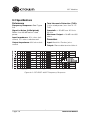
1
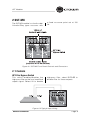
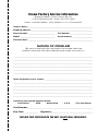
SST-Modules
This manual describes the following models:
SST-MX
SST-SX
SST-SBSC
SST-SBSC 3632T
SST-4622
SST-3632
SST-4632
SST-SBSC 4632T
© 2003 by Crown Audio, Inc., P.O. Box 1000, Elkhart, IN 46515-1000 U.S.A.
Telephone: 574-294-8000. Fax: 574-294-8329. SST modules are produced by
Crown Audio, Inc. Trademark Notice: Crown is a registered trademark of Crown
International. Other trademarks are the property of their respective owners.
Obtaining Other Language Versions:
To obtain information in another language about the use of this
product, please contact your local Crown Distributor. If you need assistance locating your local distributor, please contact Crown at 574-294-8200.
Note: The information provided in this manual was deemed accurate as of the
publication date. However, updates to this information may have occurred.
To obtain the latest version of this manual, please visit the Crown website at
www.crownaudio.com.
Printed on
recycled paper.
132166-3B
4/03
SST Modules
STOP!
Crown SST modules may only be installed by Crown or an authorized
Warranty Service Center. The name of a Service Center near you may
be found online at www.crownaudio.com, or by contacting Crown
Factory Service at:
Crown Factory Service
1718 W. Mishawaka Rd., Elkhart, IN 46515 USA
Phone: 800-342-6939 (North America, Puerto Rico and Virgin Islands)
or 574-294-8200 Fax: 574-294-8301
Internet: http://www.crownaudio.com
The information furnished in this manual does not include all of the
details of design, production, or variations of the equipment. Nor does
it cover every possible situation which may arise during operation or
maintenance. If you need special assistance beyond the scope of this
manual, please contact Crown Customer Service.
Page 2
Reference Manual
SST Modules
Contents
1 Welcome........................ 4
5 SST-4622.......................17
1.1 Wiring ................................... 4
5.1 System Setup ..................... 17
2 SST-MX.......................... 5
5.2 Specifications ..................... 18
2.1 Controls ................................ 5
6 SST-3632.......................19
2.2 System Setup ....................... 6
6.1 System Setup ..................... 19
2.3 Block Diagram...................... 8
6.2 Specifications ..................... 20
2.4 Specifications ....................... 8
7 SST-4632.......................21
3 SST-SX .......................... 9
7.1 System Setup ..................... 21
3.1 Controls ................................ 9
7.2 Specifications ..................... 22
3.2 System Setup ..................... 10
8 SST-SBSC 3632T..............23
3.3 Block Diagram.................... 12
8.1 System Setup ..................... 23
3.4 Specifications ..................... 12
8.2 Specifications ..................... 24
4 SST-SBSC ......................13
9 SST-SBSC 4632T..............25
4.1 Specifications ..................... 13
9.1 System Setup ..................... 25
4.2 Features.............................. 13
9.2 Specifications ..................... 26
4.3 Block Diagram.................... 14
10 Service........................27
4.4 Input Wiring and Crossover
Frequencies.............................. 15
Appendix .........................29
4.5 System Setup ..................... 16
Reference Manual
Page 3
SST Modules
1 Welcome
Crown®’s System Solution Topology
(SST) modules bring you superior
control and flexibility with the convenience and cost savings of plug-in
processing. SSTs plug quickly and
easily into the back of your amp.
loss found with passive crossover
networks). Compact and versatile,
Crown SST modules continue the
Crown tradition for fast setup, greatsounding output and exceptional
value.
When you use a Crown SST module
to split the power drive to the
loudspeaker components, you gain
a wide range of advantages, including:
1.1 Wiring
1. Increased gain because the
insertion loss of passive crossover networks is eliminated.
2. Consistent power bandwidth:
power bandwidth is changed
in multi-way passive systems if
transducers change impedance
or vaporize (blow up).
3. Levels can be matched more
accurately to the components.
4. Quicker troubleshooting.
5. Improved dynamic range.
6. Better protection of components
due to steep 24-dB/octave filters.
With hard-wired precision components, SST modules deliver consistent bandwidth control, more accurate level matching, and increased
gain (with none of the insertion
Page 4
All SST modules feature balanced
inputs. Some models also feature
balanced outputs for routing signals
to other amplifiers in biamped and
triamped systems.
Following are the standard wiring
conventions to follow when wiring
balanced connections to SST modules:
XLR (AES Standard)
Pin 1:
Pin 2:
+
Pin 3:
–
Tip Ring Sleeve
Tip:
+
Ring:
–
Sleeve:
Barrier Block and Terminal Block
connections should be wired as
marked on the SST front panel.
Reference Manual
SST Modules
2 SST-MX
The SST-MX module is a fourth-order
Linkwitz-Riley type crossover with
a fixed crossover point set at 100
Hz.
Figure 2.1 SST-MX Front Panel Controls and Connectors
2.1 Controls
HP Filter Bypass Switch
This switch enables/disables the
high-pass filter on the local amplified
output signal. Select IN to enable
high-pass filter; select BYPASS to
disable filter for these outputs.
Figure 2.2 Typical Input Wiring
Reference Manual
Page 5
SST Modules
2.2 System Setup
Typical input wiring is shown in Figure
2.2 on the previous page.
Stereo Mode
Standard stereo-mode output configuration (shown in Figure 2.3)
routes the signal in the following
manner: low-frequency signal from
the amplifier’s Channel 1 input is sent
to the Channel 1 barrier block output;
low-frequency signal from Channel 2
input is sent to the Channel 2 barrier
block output; high-frequency signal
from Channel 1 input is sent to the
local (amplified) Channel 1 output;
high-frequency signal from Channel
2 input is sent to the local (amplified)
Channel 2 output.
Figure 2.3 Typical stereo configuration using Crown SST-compatible
amplifier and the SST-MX crossover module.
Page 6
Reference Manual
SST Modules
Bridge-Mono Mode
Standard bridge-mono-mode output
configuration (shown in Figure 2.4)
routes the signal in the following
manner: low-frequency signal from
the amplifier’s Channel 1 input is
sent to the Channel 1 barrier block
output; high-frequency signal from
Channel 1 input is sent to the local
(amplified) Channel 1 output.
Note: Only the Channel 1 audio
signal is required to drive the amplifier during mono operation. If you
are using the SST-MX module with
the amplifier in mono mode, be sure
to turn your Channel 2 level controls
all the way down.
Figure 2.4 Typical Bridge-Mono configuration using Crown SST-compatible
amplifier and the SST-MX crossover module.
Reference Manual
Page 7
SST Modules
High-Pass Filter Bypass
When activated, the High-Pass Filter
Bypass (Section 2.1) allows the fullrange signal to be sent to the local
(amplified) Channel 1 and Channel 2
outputs, while still providing filtered
low-frequency output to the Channel
1 and Channel 2 barrier block
outputs. This configuration works
well if you have full-range speakers
driven by the main amplifier, plus
dual subs on an auxiliary amp for
sub-bass output.
2.3 Block Diagram
100HzLP
24dB/oct.slope
–
3
CH1
2
+
1
100HzHP
24dB/oct.slope
IN
TB
HOST
AMPLIFIER
CH1INPUT
+
+
–
–
CH1SUBOUT
BYP ASS
100HzLP
100HzHP
100HzHP
24dB/oct.slope
IN
–
–
CH2SUBOUT
HOST
AMPLIFIER
CH2INPUT
+
+
BYP ASS
100HzLP
24dB/oct.slope
–
3
CH2
2
1
+
Figure 2.5 SST-MX Block Diagram
2.4 Specifications
Note: Specifications describe typical results
using the module installed in a Crown SSTcompatible amplifier. All measurements are
in Stereo mode with 8-ohm loads and an
input sensitivity of 26-dB gain at 1-kHz
rated power unless otherwise specified.
Specifications for units supplied outside
the U.S.A. may vary slightly at different AC
voltages and frequencies.
Input Impedance: 20 k ohms balanced, 10 k ohms unbalanced.
Frequency Response: ±0.1 dB
from 20 Hz to 20 kHz.
Crosstalk: > 50 dB from 20 Hz to
20 kHz.
Signal to Noise (A-Weighted):
Better than 85 dB below rated
power.
Maximum Output: +18 dB into 600
ohms.
Page 8
Output Impedance: 600 ohms
balanced.
Total Harmonic Distortion (THD):
1 kHz rated power, less than 0.1%
true THD.
Reference Manual
SST Modules
3 SST-SX
The SST-SX module is a fourthorder Linkwitz-Riley type crossover
switchable between 80 Hz and 120
Hz. It also includes summed lowfrequency output.
Figure 3.1 SST-SX Controls and Connectors
3.1 Controls
80/120 Hz Crossover Selector
HP Filter Bypass Switch
A two-position switch, located on the
front panel of the module, is used to
select a crossover frequency of 80
or 120 Hz for both channels 1 and 2
of the local (amplified) signals. This
switch also determines the LP Filter
frequency routed to the Mono Sub
Out connector.
This two-position switch enables/
disables the high-pass filter on the
Channel 1 and 2 local (amplified)
signals.The HP Filter Bypass Switch
does not affect signals routed to the
Mono Sub Out connector.
Figure 3.2 Typical Input Wiring
Reference Manual
Page 9
SST Modules
3.2 System Setup
Typical input wiring is shown in Figure
3.2 on the previous page.
Stereo Mode
For standard stereo-mode output
wiring, connect your system components as shown in Figure 3.3. This
configuration routes the signal in
the following manner: low-frequency
signals from the local amplifier are
sent to the male XLR output; highfrequency signals from the local
amplifier’s Channel 1 input are sent
to the local (amplified) Channel 1
output; high-frequency signal from
the host amplifier’s Channel 2 input
are sent to the local (amplified)
Channel 2 output.
Figure 3.3 Typical Stereo with Mono Sub Configuration Using the
SST-SX Crossover Module
Page 10
Reference Manual
SST Modules
Bridge-Mono Mode
For standard bridge-mono-mode
output wiring, connect your system
components as shown in Figure
3.4. This configuration routes the
signals in the following manner:
low-frequency signals from the host
amplifier are sent to the male XLR
output; high-frequency signal from
the host amplifier’s Channel 1 input
are sent to the local (amplified)
Channel 1 output.
Note: Only the Channel 1 audio
signals are required to drive the
amplifier during mono operation. If
you are using the SST-SX module with
a Crown SST-compatible amplifier
in mono mode, be sure to turn your
Channel 2 level control all the way
down.
Figure 3.4 Typical Bridge-Mono Configuration Using the SST-SX
Crossover Module
Reference Manual
Page 11
SST Modules
High-Pass Filter Bypass
When activated, the High-Pass Filter
Bypass (Section 3.1) allows the fullrange signal to be sent to the local
(amplified) Channel 1 and Channel 2
outputs, while still providing filtered
low-frequency output to the Mono
Summed Male XLR Output. This
configuration works well if you have
full-range speakers driven by the
main amplifier, plus a sub on an
auxiliary amp for sub-bass output.
3.3 Block Diagram
80 / 120 Hz HP
24 dB/oct. slope
CH1
3
2
1
OUT
BYPASS
HOST
AMPLIFIER
CH1 INPUT
IN
80 Hz
120 Hz
80 / 120 Hz LP
24 dB/oct. slope
SUB OUT
(SUMMED)
80 / 120 Hz LP
24 dB/oct. slope
80 Hz
OUT
CH2
120 Hz
BYPASS
3
2
1
HOST
AMPLIFIER
CH2 INPUT
IN
80 / 120 Hz HP
24 dB/oct. slope
Figure 3.5 SST-SX Block Diagram
3.4 Specifications
Note: Specifications describe typical results
using the module installed in a Crown SSTcompatible amplifier. All measurements are
in Stereo mode with 8-ohm loads and an
input sensitivity of 26-dB gain at 1-kHz
rated power unless otherwise specified.
Specifications for units supplied outside
the U.S.A. may vary slightly at different AC
voltages and frequencies.
Total Harmonic Distortion (THD):
1-kHz rated power, 1.0% or less
true THD from 20 Hz to 20 kHz.
Performance
Input Impedance: Nominally 20 k
ohms, balanced. Nominally 10 k
ohms, unbalanced.
Frequency Response: ±0.1 dB
from 20 Hz to 20 kHz at 1 watt.
Signal to Noise Ratio,
A-Weighted: Better than 105 dB
below rated 1-kHz power;
20 Hz to 20 kHz: Better than 100
dB below rated 1-kHz power.
Page 12
Crosstalk: Better than 50 dB below
rated power, 20 Hz to 20 kHz.
Input/Output
Output Impedance: 600 ohms,
balanced.
Maximum Output: +15 dBm into
600 ohms.
Reference Manual
SST Modules
4 SST-SBSC
The Crown SST-SBSC modules
are stereo crossover networks
with equalization and summed
bass output. Truly professional
crossovers, SST-SBSC modules use
hard-wired precision components
that stay at the factory-set frequencies for consistent bandwidth
control.
SST (System Solution Topologies)
modules install into the back of
Crown SST-compatible amplifiers,
saving rack space and simplifying
system wiring.
Several SST-SBSC modules with
different crossover frequencies are
available (see Table 1 on page
15).
4.1 Specifications
Signal to Noise (A-Weighted):
Better than 85 dB below rated
power.
Input Impedance: 20 k ohms balanced, 10 k ohms unbalanced.
Output Impedance: 600 ohms
balanced.
Total Harmonic Distortion (THD):
1 kHz rated power, less than 0.1%
true THD.
Crosstalk: > 50 dB from 20 Hz
to 20 kHz.
Maximum Output: +18 dB into
600 ohms.
Figure 4.1 SST-SBSC Front Panel
Connectors
4.2 Features
• Stereo biamp and sub output.
Two in, five out.
• Mono summing of sub output
for driving subwoofers.
• Certain modules have 2.8-kHz
CD horn equalization.
• Certain modules are designed
specifically for JBL ScreenArray™ loudspeakers.
• Neutrik® Combo input jacks.
• Removable barrier block jacks
for balanced output to other
components.
• 18-dB/octave high-pass filter on
sub and 18-dB/octave highpass filter on low-frequency outputs.
• 24-dB/octave low-pass filter on
high-frequency outputs.
Reference Manual
Page 13
SST Modules
4.3 Block Diagram
Figure 4.2 SST-SBSC Block Diagram
Page 14
Reference Manual
SST Modules
4.4 Input Wiring and Crossover Frequencies
Figure 4.3 Typical Input Wiring
Table 1: SBSC MODULES CROSSOVER FREQUENCIES
MODEL
NUMBER
CHANNEL 1 & 2
LOW FREQUENCY
HIGH PASS
LOW PASS
SUMMED SUB
HIGH FREQUENCY
HIGH PASS
LOW PASS
CD
BOOST
OUTPUT
HIGH PASS
LOW PASS
SBSCX1
80
800
800
16K
32
80
Y
SBSCX2
80
500
500
16K
32
80
Y
SBSCX12
32
120
120
20K
32
120
N
SBSCX17
32
350
350
20K
32
80
N
SBSCX19
32
1.25K
1.25K
20K
32
100
Y
SBSCX3632T
500
1.2K
1.5K
22.5K
35
450
Y
SBSCX4632T
250
1.2K
1.5K
22.5K
35
250
Y
SBSCJBL4675
32
1.2K
1K
22.5K
32
100
N
SBSCJBL5672
250
2.4K
2.5K
22.5K
32
300
N
Reference Manual
Page 15
SST Modules
4.5 System Setup
Typical input wiring is shown in Figure
4.3 on the previous page.
Stereo
Standard stereo-mode output configuration (Figure 4.4) routes the
signal in the following manner:
Lows from SST-SBSC CH1 go
through the local amp to its CH1
speaker output.
Lows from SST-SBSC CH2 go
through the local amp to its CH2
speaker output.
Highs from SST-SBSC CH1 go to its
Output A, and from there through
aux amp CH1 to its CH1 speaker
output.
Highs from SST-SBSC CH2 go to its
Output C, and from there through
aux amp CH2 to its CH2 speaker
output.
Sub-bass signal (from SST-SBSC
CH1 and CH2 summed) goes to
SST-SBSC Output B, and from there
through sub amp CH1 to its CH1
speaker output.
Figure 4.4 Typical stereo configuration using Crown SST-compatible amplifier
and an SST-SBSC crossover module
Page 16
Reference Manual
SST Modules
The remaining SST modules described in this manual are designed specifically
for use with JBL® ScreenArray ® cinema speaker systems. Each SST model is
optimized for use with one specific JBL ScreenArray speaker model.
5 SST-4622
The SST-4622 provides custom
crossover and equalization optimized
for the JBL ScreenArray model 4622
cinema speaker system.
5.1 System Setup
Connect your system components
as shown in Figure 5.2.
Note: The amplifier should be placed
in Stereo (Dual) mode.
Figure 5.1 SST-4622 Front Panel
Connector
Figure 5.2 Stereo configuration using a Crown SST-compatible amplifier
and the SST-4622 module.
Reference Manual
Page 17
SST Modules
5.2 Specifications
Frequency Response: See Figure
5.3.
Input Impedance: 20 k ohms balanced, 10 k ohms unbalanced.
Signal to Noise Ratio: 90 dB, A
weighted.
Connectors
Input: Electronically Balanced,
3-position removable terminal
block.
Figure 5.3 SST-4622 Frequency Response
Page 18
Reference Manual
SST Modules
6 SST-3632
The SST-3632 provides custom
crossover and equalization optimized for the JBL ScreenArray model
3632 cinema speaker system.
6.1 System Setup
Connect your system components
as shown in Figure 6.2.
Note: The amplifier should be placed
in Stereo (Dual) mode.
Figure 6.1 SST-3632 Front Panel
Connector
Figure 6.2 Stereo configuration using a Crown SST-compatible amplifier
and the SST-3632 module.
Reference Manual
Page 19
SST Modules
6.2 Specifications
Frequency Response: See Figure
6.3.
Input Impedance: 20 k ohms balanced, 10 k ohms unbalanced.
Signal to Noise Ratio: 90 dB, A
weighted.
Connectors
Input: Electronically Balanced,
3-position removable terminal
block.
Figure 6.3 SST-3632 Frequency Response
Page 20
Reference Manual
SST Modules
7 SST-4632
The SST-4632 provides custom
crossover and equalization optimized for the JBL ScreenArray model
4632 cinema speaker system.
7.1 System Setup
Connect your system components
as shown in Figure 7.2.
Note: The amplifier should be placed
in Stereo (Dual) mode.
Figure 7.1 SST-4632 Front Panel
Connector
Figure 7.2 Stereo configuration using a Crown SST-compatible amplifier
and the SST-4632 module.
Reference Manual
Page 21
SST Modules
7.2 Specifications
Frequency Response: See Figure
7.3.
Input Impedance: 20 k ohms balanced, 10 k ohms unbalanced.
Signal to Noise Ratio: 90 dB, A
weighted.
Connectors
Input: Electronically Balanced,
3-position removable terminal
block.
Figure 7.3 SST-4632 Frequency Response
Page 22
Reference Manual
SST Modules
8 SST-SBSC 3632T
The SST-SBSC 3632T is an SSTSBSC factory-configured to provide
crossover, equalization and signal
routing specifically for the triamped
JBL ScreenArray model 3632T
cinema speaker system.
8.1 System Setup
Your system should be wired as
shown in Figure 8.2.
Note: The amplifier should be placed
in Stereo (Dual) mode.
Figure 8.1 SST-SBSC 3632T
Front Panel Connectors
Figure 8.2 SST-SBSC 3632T Screen Channel Wiring
Left, Center and Right Screen Channels Wired Identically
Reference Manual
Page 23
SST Modules
8.2 Specifications
Performance
Frequency Response: See Figure
8.3.
Signal to Noise (A-Weighted):
Better than 85 dB below rated
power.
Input Impedance: 20 k ohms balanced, 10 k ohms unbalanced.
Output Impedance: 600 ohms balanced.
Total Harmonic Distortion (THD):
1 kHz rated power, less than 0.1%
THD.
Crosstalk: > 50 dB from 20 Hz to
20 kHz.
Maximum Output: +18 dB into 600
ohms.
Connectors
Input: Neutrik® Combo jacks.
Output: Removable terminal block.
Figure 8.3 SST-SBSC 3632T Frequency Response
Page 24
Reference Manual
SST Modules
9 SST-SBSC 4632T
The SST-SBSC 4632T is an SSTSBSC factory-configured to provide
crossover, equalization and signal
routing specifically for the triamped
JBL ScreenArray model 4632T
cinema speaker system.
9.1 System Setup
Your system should be wired as
shown in Figure 9.2.
Note: The amplifier should be placed
in Stereo (Dual) mode.
Figure 9.1 SST-SBSC 4632T Front
Panel Connectors
4632T
High
Not
Used
Not
Used
Channel 2 Output
Amp in Dual Mode
4632T
Mid
OUTPUTS
CH2
CH1
Channel 1 Output
Not Used
From Cinema Processor
4632T
Low
Bridged Output
Amp in Bridge Mode
INPUTS
CH2
Not Used
CH1
OUTPUTS
CH2
CH1
Note: for best results,
lift the signal ground
at the input of this amp.
Figure 9.2 SST-SBSC 4632T Screen Channel Wiring
Left, Center and Right Screen Channels Wired Identically
Reference Manual
Page 25
SST Modules
9.2 Specifications
Performance
Frequency Response: See Figure
9.3.
Signal to Noise (A-Weighted):
Better than 85 dB below rated
power.
Input Impedance: 20 k ohms balanced, 10 k ohms unbalanced.
Output Impedance: 600 ohms balanced.
Total Harmonic Distortion (THD):
1 kHz rated power, less than 0.1%
THD.
Crosstalk: > 50 dB from 20 Hz to
20 kHz.
Maximum Output: +18 dB into 600
ohms.
Connectors
Input: Neutrik® Combo jacks.
Output: Removable terminal block.
Figure 9.3 SST-SBSC 4632T Frequency Response
Page 26
Reference Manual
SST Modules
10 Service
10.1 Worldwide Service
Service may be obtained from an
authorized service center. (Contact
your local Crown/Amcron representative or our office for a list of authorized
service centers.) To obtain service,
simply present the bill of sale as
proof of purchase along with the
defective unit to an authorized
service center. They will handle the
necessary paperwork and repair.
Remember to transport your unit in
the original factory pack.
10.2 US and Canada Service
Service may be obtained in one of
two ways: from an authorized service
center or from the factory. You may
choose either. It is important that you
have your copy of the bill of sale as
your proof of purchase.
10.2.1 Service at a US or Canada
Service Center
This method usually saves the most
time and effort. Simply present your
bill of sale along with the defective
unit to an authorized service center
to obtain service. They will handle
the necessary paperwork and repair.
Remember to transport the unit in
the original factory pack. A list of
authorized service centers in your
area can be obtained from the Crown
website at www.crownaudio.com, or
by calling Crown Factory Service.
10.2.2 Factory Service
To obtain factory service, fill out the
service information page found in
the back of this manual and send it
along with your proof of purchase
Reference Manual
and the defective unit to the Crown
factory.
For warranty service, we will pay
for ground shipping both ways in
the United States. Contact Crown
Factory Service to obtain prepaid
shipping labels prior to sending the
unit. Or, if you prefer, you may prepay
the cost of shipping, and Crown will
reimburse you. Send copies of the
shipping receipts to Crown Factory
Service to receive reimbursement.
Your repaired unit will be returned
via UPS ground. Please contact us if
other arrangements are required.
10.2.3 Factory Service Shipping
Instructions:
1. Before sending a Crown product to
the factory for service, first call the
Crown Factory Service for a return
authorization (RA) number.
2. Be sure to fill out the service
information form that follows and
enclose it with your shipment,
either inside the box or in a
packing slip envelope securely
attached to the outside of the
shipping carton. Do not send
the service information form separately. If you are sending the
unit from a Shipping Center, we
recommend taping the form to
the product. We also recommend
recording the serial number and
model before shipping for your
reference.
3. To ensure the safe transportation of
your unit to the factory, ship it in an
original factory packing container.
Page 27
SST Modules
If you don’t have the original
carton, you may obtain a product
service foam-in-place shipping
pack from the Crown Factory
Service at the number listed
below. For non-warranty service,
you may also provide your own
shipping pack, however we
still recommend using a Crown
Supplied Shipping Container.
Minimum recommended requirements for materials are as follows:
275 P.S.I. burst test Double-Wall
carton that allows for 2-inch solid
Styrofoam on all six sides of unit
or 3 inches of plastic bubble
wrap on all six sides of unit;
securely seal the package with
an adequate carton sealing
tape. Do not use light boxes or
“peanuts.” Damage caused by
poor packing cannot be covered
under warranty.
4. Do not ship the unit in any kind of
cabinet (wood or metal). Ignoring this warning may result in
extensive damage to the unit and
the cabinet. Accessories are not
needed-do not send the product
documentation, cables and other
hardware.
If you have any questions, please
contact Crown Factory Service.
Crown Factory Service
1718 W. Mishawaka Rd.,
Elkhart, Indiana 46517 U.S.A.
Telephone: 574-294-8200
800-342-6939 (North America,
Puerto Rico, and Virgin Islands only)
Facsimile:
574-294-8301 (Technical Support)
574-294-8124 (Factory Service)
Internet:
http://www.crownaudio.com
Page 28
Reference Manual
SST Modules
Appendix
Warranty Statements
SST-SBSC Custom Configuration Form
Crown Factory Service Form
Reference Manual
Page 29
3
YEAR
UNITED STATES & CANADA
SUMMARY OF WARRANTY
Crown International, Inc., 1718 West Mishawaka Road, Elkhart, Indiana 46517-4095 U.S.A.
warrants to you, the ORIGINAL PURCHASER and ANY SUBSEQUENT OWNER of each
NEW Crown product, for a period of three (3) years from the date of purchase by the
original purchaser (the “warranty period”) that the new Crown product is free of defects in
materials and workmanship. We further warrant the new Crown product regardless of the
reason for failure, except as excluded in this Warranty.
ITEMS EXCLUDED FROM THIS CROWN WARRANTY
This Crown Warranty is in effect only for failure of a new Crown product which occurred
within the Warranty Period. It does not cover any product which has been damaged
because of any intentional misuse, accident, negligence, or loss which is covered under
any of your insurance contracts. This Crown Warranty also does not extend to the new
Crown product if the serial number has been defaced, altered, or removed.
THREE YEAR
FULL WARRANTY
WHAT THE WARRANTOR WILL DO
We will remedy any defect, regardless of the reason for failure (except as excluded), by
repair, replacement, or refund. We may not elect refund unless you agree, or unless we
are unable to provide replacement, and repair is not practical or cannot be timely made. If
a refund is elected, then you must make the defective or malfunctioning product available
to us free and clear of all liens or other encumbrances. The refund will be equal to the
actual purchase price, not including interest, insurance, closing costs, and other finance
charges less a reasonable depreciation on the product from the date of original purchase.
Warranty work can only be performed at our authorized service centers or at the factory.
Warranty work for some products can only be performed at our factory. We will remedy the
defect and ship the product from the service center or our factory within a reasonable time
after receipt of the defective product at our authorized service center or our factory. All
expenses in remedying the defect, including surface shipping costs in the United States,
will be borne by us. (You must bear the expense of shipping the product between any
foreign country and the port of entry in the United States and all taxes, duties, and other
customs fees for such foreign shipments.)
HOW TO OBTAIN WARRANTY SERVICE
You must notify us of your need for warranty service within the warranty period. All
components must be shipped in a factory pack, which, if needed, may be obtained
from us free of charge. Corrective action will be taken within a reasonable time of the
date of receipt of the defective product by us or our authorized service center. If the
repairs made by us or our authorized service center are not satisfactory, notify us or our
authorized service center immediately.
DISCLAIMER OF CONSEQUENTIAL & INCIDENTAL DAMAGES
YOU ARE NOT ENTITLED TO RECOVER FROM US ANY INCIDENTAL DAMAGES
RESULTING FROM ANY DEFECT IN THE NEW CROWN PRODUCT. THIS INCLUDES ANY
DAMAGE TO ANOTHER PRODUCT OR PRODUCTS RESULTING FROM SUCH A DEFECT.
SOME STATES DO NOT ALLOW THE EXCLUSION OR LIMITATIONS OF INCIDENTAL
OR CONSEQUENTIAL DAMAGES, SO THE ABOVE LIMITATION OR EXCLUSION MAY
NOT APPLY TO YOU.
WARRANTY ALTERATIONS
No person has the authority to enlarge, amend, or modify this Crown Warranty. This Crown
Warranty is not extended by the length of time which you are deprived of the use of the new
Crown product. Repairs and replacement parts provided under the terms of this Crown
Warranty shall carry only the unexpired portion of this Crown Warranty.
DESIGN CHANGES
We reserve the right to change the design of any product from time to time without
notice and with no obligation to make corresponding changes in products previously
manufactured.
LEGAL REMEDIES OF PURCHASER
THIS CROWN WARRANTY GIVES YOU SPECIFIC LEGAL RIGHTS, YOU MAY ALSO HAVE
OTHER RIGHTS WHICH VARY FROM STATE TO STATE. No action to enforce this Crown
Warranty shall be commenced after expiration of the warranty period.
THIS STATEMENT OF WARRANTY SUPERSEDES ANY OTHERS
CONTAINED IN THIS MANUAL FOR CROWN PRODUCTS.
7/01
WORLDWIDE EXCEPT US & CANADA
SUMMARY OF WARRANTY
Crown International, Inc., 1718 West Mishawaka Road, Elkhart, Indiana 46517-4095 U.S.A.
warrants to you, the ORIGINAL PURCHASER and ANY SUBSEQUENT OWNER of each
NEW Crown1 product, for a period of three (3) years from the date of purchase by the
original purchaser (the “warranty period”) that the new Crown product is free of defects in
materials and workmanship, and we further warrant the new Crown product regardless of
the reason for failure, except as excluded in this Crown Warranty.
3
YEAR
1 Note: If your unit bears the name “Amcron,” please substitute it for the name
“Crown” in this warranty.
ITEMS EXCLUDED FROM THIS CROWN WARRANTY
This Crown Warranty is in effect only for failure of a new Crown product which occurred
within the Warranty Period. It does not cover any product which has been damaged
because of any intentional misuse, accident, negligence, or loss which is covered under
any of your insurance contracts. This Crown Warranty also does not extend to the new
Crown product if the serial number has been defaced, altered, or removed.
WHAT THE WARRANTOR WILL DO
HOW TO OBTAIN WARRANTY SERVICE
You must notify your local Crown inporter of your need for warranty service within the
warranty period. All components must be shipped in the original box. Corrective action
will be taken within a reasonable time of the date of receipt of the defective product by
our authorized service center. If the repairs made by our authorized service center are not
satisfactory, notify our authorized service center immediately.
DISCLAIMER OF CONSEQUENTIAL & INCIDENTAL DAMAGES
YOU ARE NOT ENTITLED TO RECOVER FROM US ANY INCIDENTAL DAMAGES
RESULTING FROM ANY DEFECT IN THE NEW CROWN PRODUCT. THIS INCLUDES
ANY DAMAGE TO ANOTHER PRODUCT OR PRODUCTS RESULTING FROM SUCH
A DEFECT.
WARRANTY ALTERATIONS
No person has the authority to enlarge, amend, or modify this Crown Warranty. This Crown
Warranty is not extended by the length of time which you are deprived of the use of the new
Crown product. Repairs and replacement parts provided under the terms of this Crown
Warranty shall carry only the unexpired portion of this Crown Warranty.
DESIGN CHANGES
We reserve the right to change the design of any product from time to time without
notice and with no obligation to make corresponding changes in products previously
manufactured.
LEGAL REMEDIES OF PURCHASER
No action to enforce this Crown Warranty shall be commenced after expiration of
the warranty period.
THIS STATEMENT OF WARRANTY SUPERSEDES ANY OTHERS
CONTAINED IN THIS MANUAL FOR CROWN PRODUCTS.
12/01
THREE YEAR
FULL WARRANTY
We will remedy any defect, regardless of the reason for failure (except as excluded), by
repair, replacement, or refund. We may not elect refund unless you agree, or unless we
are unable to provide replacement, and repair is not practical or cannot be timely made. If
a refund is elected, then you must make the defective or malfunctioning product available
to us free and clear of all liens or other encumbrances. The refund will be equal to the
actual purchase price, not including interest, insurance, closing costs, and other finance
charges less a reasonable depreciation on the product from the date of original purchase.
Warranty work can only be performed at our authorized service centers. We will remedy
the defect and ship the product from the service center within a reasonable time after
receipt of the defective product at our authorized service center.
Crown Factory Service Information
Shipping Address: Crown Factory Service,
1718 W. Mishawaka Rd., Elkhart, IN U.S.A. 46517
Phone: 1-800-342-6939 or 1-574-294-8200 Fax: 1-574-294-8124
Owner’s Name:___________________________________________________________
Shipping Address:________________________________________________________
Phone Number: ________________________
Fax Number: ____________________
Model: ________________________________
Serial Number: __________________
Purchase Date: __________________________________________________________
NATURE OF PROBLEM
(Be sure to describe the conditions that existed when the
problem occurred and what attempts were made to correct it.)
________________________________________________________________________
________________________________________________________________________
________________________________________________________________________
________________________________________________________________________
________________________________________________________________________
________________________________________________________________________
Other equipment in your system: ___________________________________________
________________________________________________________________________
________________________________________________________________________
________________________________________________________________________
________________________________________________________________________
________________________________________________________________________
If warranty has expired, payment will be:
Cash/Check
VISA
MasterCard
C.O.D.
P.O. from Dealer
Card Number:____________________________________________________
Exp. Date: ___________
Signature:_________________________________
ENCLOSE THIS PORTION WITH THE UNIT. DO NOT MAIL SEPARATELY.