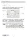
1
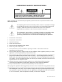
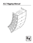
Software Version 3.02
Telex Communications (UK) Limited,
Klark Teknik Building,
Walter Nash Road,
Kidderminster.
Worcestershire.
DY11 7HJ.
England.
Tel:+44 (0) 1562 741515
Fax:+44 (0) 1562 745371
Email: [email protected]
Website: www.klarkteknik.com
DN9848 Loudspeaker Processor Operators Manual
DOC02-DN9848 Issue 2.0 - January 2005
(c) Telex Communications (UK) Limited.
In line with the company’s policy of continual improvement, specifications and function may be
subject to change without notice. This Operators Manual was correct at the time of writing. E&OE.
IMPORTANT SAFETY INSTRUCTIONS
WARNING: TO REDUCE THE RISK OF FIRE OR ELECTRIC SHOCK,
DO NOT EXPOSE THIS APPLIANCE TO RAIN OR MOISTURE
AVIS:
RISQUE DE CHOC ELECTRIQUE. NE PAS OUVRIR
These symbols are internationally accepted symbols that warn of potential hazards with
electrical products.
The lightning flash with arrowhead symbol, within an equilateral triangle
is intended to alert the user to the presence of uninsulated “dangerous
voltage” within the product's enclosure that may be of sufficient
magnitude to constitute a risk of electric shock to persons.
The exclamation point within an equilateral triangle is intended to alert
the user to the presence of important operating and maintenance
(servicing) instructions in the literature accompanying the appliance.
1. Read these instructions.
2. Keep these instructions.
3. Heed all warnings.
4. Follow all instructions.
5. Do not use this apparatus near water.
6. Clean only with a dry cloth.
7. Do not block any of the ventilation openings. Install in accordance with the
manufacturers instructions.
8. Do not install near any heat sources such as radiators, heat registers, stoves, or other
apparatus (including amplifiers) that produce heat.
9. Do not defeat the safety purpose of the polarized or grounding-type plug. A polarized
plug has two blades with one wider than the other. A grounding type plug has two
blades and a third grounding prong. The wide blade or the third prong are provided for
your safety. If the provided plug does not fit into your outlet, consult an electrician for
replacement of the obsolete outlet.
10. Protect the power cord from being walked on or pinched particularly at plugs,
convenience receptacles, and the point where they exit from the apparatus.
11. Only use attachments / accessories specified by the manufacturer.
12. Unplug this apparatus during lightning storms or when unused for long periods of time.
13. Refer all servicing to qualified personnel. Servicing is required when the apparatus has
been damaged in any way, such as power-supply cord or plug is damaged, liquid has
been spilled or objects have fallen into the apparatus, the apparatus has been exposed
to rain or moisture, does not operate normally, or has been dropped.
IEC-60065-Edn7-KT
Telex Communications (UK) Limited, Klark Teknik Building,
Walter Nash Road, Kidderminster. Worcs. DY11 7HJ. England.
Tel: +44 1562 741515 Fax: +44 1562 745371
www.midasconsoles.com www.klarkteknik.com
DECLARATION OF CONFORMITY
We,
Telex Communications (UK) Limited
of,
Klark Teknik Building, Walter Nash Road, Kidderminster, Worcestershire, DY11 7HJ.
Declare that a sample of the following product:Product Type Number
DN9848
Product Description
Loudspeaker
Processor
Nominal Voltage(s)
115V AC
230V AC
Current
200mA
100mA
Freq
50/60Hz
to which this declaration refers, is in conformity with the following directives and/or standards:Directive(s)
Test Standard(s)
89/336/EEC Electromagnetic Compatibility Directive
amended by 92/31/EEC & 93/68/EEC 73/23/EEC,
Low Voltage Directive, amended by 93/68/EEC
Generic Standard Using EN55103 Limits and Methods
EN50081/1
Class B Conducted Emissions PAVI
EN55103
Class B Radiated Emissions PAVI
EN55103
Fast Transient Bursts at 2kV
EN61000-4-4
Static Discharge at 4kV
EN61000-4-2
Electrical Stress Test
EN60204
Electrical Safety
UL6500-99
CAN/CSA E60065-00
Signed: ............................
Name: Simon Harrison
Date:1th January 2005
Authority: Research and Development Director, Telex Communications (UK) Limited
Attention!
Where applicable, the attention of the specifier, purchaser, installer or user is drawn to
special limitations of use which must be observed when these products are taken into
service to maintain compliance with the above directives. Details of these special measures
and limitations to use are available on request and are available in product manuals.
Company registration No. 2414018. A Subsidiary of Telex Communications Inc.
Thank You For Using This Klark Teknik Product
Our engineers have designed this product with uncompromising dedication to providing the superb
audio performance, ease of use and rugged reliability that meets the demands of live sound
engineering.
Please take time to complete and return the Klark Teknik three-year warranty registration card and,
to obtain maximum performance with minimum effort, refer to this operators manual. Please ensure
that you read both the Important Safety Instructions and Attention! pages.
Finally, enjoy your new DN9848!
CONTENTS
ATTENTION! ......................................................................................... 1
1.
INTRODUCING THE DN9848 .........................................................................3
2.
FRONT PANEL ..........................................................................................4
3.
REAR PANEL ............................................................................................5
4.
PROGRAMMING SETTINGS ............................................................................6
4.1.
The DN9848 Programming Panel .................................................................................. 6
4.2.
Navigating the DN9848 Menus ..................................................................................... 6
4.2.1
Input and Output Menus ....................................................................................... 6
4.2.2
Set Up Menu ....................................................................................................... 7
4.2.3
Store and Recall................................................................................................... 7
4.2.4
Home Page ......................................................................................................... 7
5.
INPUT CHANNELS ......................................................................................9
5.1.
Brief Technical Overview ............................................................................................. 9
5.2.
Setting Input Parameters ............................................................................................ 9
5.2.1
The Input Menu ................................................................................................... 9
5.2.2
Naming the Input Channel (Page 1) ........................................................................ 9
5.2.3
Gain and Delay (Page 1) ..................................................................................... 10
5.2.4
Parametric Equalisation (Pages 2 to 13) ................................................................ 10
5.2.5
Compression (Page 14) ....................................................................................... 11
5.3.
6.
Monitoring the Input Signal ....................................................................................... 11
OUTPUT CHANNELS .................................................................................. 12
6.1.
Brief Technical Overview ........................................................................................... 12
6.2.
Setting Output Parameters ........................................................................................ 13
6.2.2
Naming the Output Channel (Page 1) .................................................................... 13
6.2.3
Routing (Page 2)................................................................................................ 13
6.2.4
Signal Invert, Delay and Output Level (Page 3) ...................................................... 14
6.2.5
Phase Adjustment (Pages 4 and 5) ...................................................................... 14
6.2.6
High Pass and Low Pass Filters (Pages 6 and 7) ...................................................... 15
6.2.7
Parametric Equalisation (Pages 2 to 13) ................................................................ 16
6.2.8
Compression (Page 14) ....................................................................................... 16
6.2.9
Output Limiter ................................................................................................... 17
6.3.
Monitoring the Output Signal...................................................................................... 17
6.4.
Output Gain and Mute - Front Panel Control ................................................................. 18
7.
DN9848 SET UP OPTIONS .........................................................................19
7.1.
General................................................................................................................... 19
7.2.
Remote Comms Channel (Page 1)............................................................................... 19
7.3.
Security Settings (Pages 2 and 3) ............................................................................... 19
7.3.1
Front Panel Lock (Page 2).................................................................................... 19
7.3.2
System Protect (Page 3)...................................................................................... 20
7.4.
LCD Lighting (Page 4) ............................................................................................... 21
7.5.
Naming (Pages 5 and 6) ............................................................................................ 21
7.6.
Delay Options (Page 7) ............................................................................................. 22
7.7.
Power Up Options (Page 8) ........................................................................................ 22
8.
STORING AND RECALLING SETTINGS ..............................................................23
9.
DN9848 REMOTE CONTROL SETUP ...............................................................25
10. APPLICATION NOTES .................................................................................27
10.1. The Advantage of DN9848 Look-Ahead Limiters ............................................................ 27
10.2. Phase-adjustment with the DN9848 ............................................................................ 29
11. TECHNICAL SPECIFICATION .........................................................................31
ATTENTION!
Please ensure that you read and follow the
IMPORTANT SAFETY INSTRUCTIONS at the front of this manual and the
SAFETY WARNINGS and INSTALLATION CONSIDERATIONS given below.
Safety Warning
To prevent shock or fire hazard, do not expose the unit to rain or moisture. To avoid electrical shock
do not remove covers. Refer servicing to qualified personnel only.
This unit is fitted with a standard fused IEC mains power socket. The unit contains a switch mode
power supply that automatically adjusts itself to 50/60Hz mains supplies in the 100 V to 240 V (+/10%) AC range. This information is printed on the rear of the unit, below the mains inlet socket.
Before connecting this unit to the mains supply, ensure that the fuse fitted is the correct type and
rating as indicated on the rear panel.
For safety reasons the mains earth lead should never be disconnected. In the event of ground loop
problems, disconnect the signal screen at one end of the connecting cables – note that this can only
be done when the unit is used within a balanced system.
Installation Considerations
Location:
Do not install this unit in a location subjected to excessive heat, dust or
mechanical vibration. Allow for adequate ventilation around the unit, making sure
the unit’s fans and vents are not obstructed. To prevent excessive heating of the
unit, avoid mounting the unit directly above power amplifiers or other devices
that radiate significant amounts of heat. Where necessary use fan cooled racks.
Cables:
To ensure correct and reliable performance, this product should only be used with
high quality, screened twisted pair audio cables, terminated with metal bodied 3pin XLR connectors (Pin 2 Hot).
Electric Fields:
Should this product be used in an electromagnetic field that is amplitude
modulated by an audio frequency signal (20Hz to 20kHz), the signal to noise ratio
may be degraded. Degradation of up to 60dB at a frequency corresponding to the
modulation signal may be experienced under extreme conditions (3V/m, 90%
modulation).
After Unpacking
Please retain the original packing for use should you need to transport or ship this unit.
Please inspect the unit carefully for any signs of damage that may have occurred in transit and notify
the courier immediately if you feel that any damage has occurred.
1
DN9848 Key Features
1. INTRODUCING THE DN9848
The DN9848 is a highly configurable, digital electronic cross-over/loudspeaker management system
comprising four balanced analogue input channels and eight balanced analogue output channels. Its
unrivalled routing flexibility enables each output to be sourced from a single input, a pair of inputs, or
all four inputs.
Each input channel features:
12 separately configurable, fully parametric equalisation stages that
may be used for room equalisation
A programmable delay of up to 1000ms
Gain control
Full range compression
Each output channel features:
Configurable high and low-pass filters for setting the cross-over characteristics
Six stages of fully parametric equalisation that may be used to
compensate for system or enclosure characteristics
Delay of up to 300ms on each output, mainly used for system time alignment
Gain control and output muting
Full range compression and full range limiting
Dual all-pass phase correction sections, the first of which can be any of the
filter or parametric EQ stages and can be adjustable in 5 degree steps
The cross-over filter may be chosen from the following types:
12dB/oct and 24dB/oct peaking (high-pass filter only)
Butterworth (6, 12, 18, 24, 36 and 48dB/octave)
Linkwitz-Riley (12 and 24dB/octave)
Bessel (12, 18, 24, 36 and 48dB/octave)
Channel programming can be performed directly from the front panel controls or remotely using the
associated Stardraw software application or Smaart real-time analysis software (via the RS-232 PC
Port or RS-485 COMMS connectors). If required, access to critical parameter menus can be password
protected, e.g. to avoid unauthorised adjustments in hire installations.
Commonly used settings can be stored for repetitive use in up to 32 lockable System memories while
varying show settings can be stored in up to 5 User memories. Also 99 Presets can be stored in nonvolatile Flash memory, including up to 25 available Factory Preset cross-over set ups for commonly
used Electro-Voice loudspeaker systems.
Klark Teknik has a policy of continuous development and may produce updates to the DN9848 host
code. These can be downloaded to the unit via the front panel PC Port. To keep up with newest
features and functions, please visit www.klarkteknik.com.
3
Controls, Connectors, Indicators
2. FRONT PANEL
1
2
6
1
3
5
4
7
8
9
Input channels A-D
Menu Access
Buttons A-D
Press to access and step through the menu pages for the
respective input. The available pages depend on the current
security setting. The button is lit when active.
Signal Level
Meters A - D
9-segment signal meters for monitoring signal level
(compressor headroom and gain reduction) and clip on the
respective channels.
2
Recall button
Press to access the Recall menu page from which a User,
System or Preset memory can be selected for recall.
3
Alphanumeric display
Displays menu pages for viewing/defining parameter values.
Values are adjusted via the DATA ENTRY encoders knobs.
4
Home (Set Up) button
Press to exit current menu page and return to default Home
page. Press and hold for 1 second to access Set Up menu,
then press to step through Set Up pages.
5
Output channels 1 - 8
Menu Access
Buttons 1-8
As for input channels.
Signal Level
Meters 1 - 8
11-segment signal meters for monitoring signal level
(compressor/limiter headroom and gain reduction) and clip
on the respective channels.
Output level and
mute control
Potentiometer control for fine-tuning/muting of output level.
Zero level refers to the level set in the output menu. Turn
control to increase/decrease level or press to mute. Red ring
lights when mute is active.
6
Data entry encoder
knobs
Used to set parameter values on menu pages
(see Section 4.1).
7
Store button
Press to access the Store menu page for storing User or
System memories.
8
PC port
8-pin mini-DIN socket for connecting to an RS-232 serial
port on a PC or other remote control device. (XLR connector
is provided on the rear panel for remote control via RS-485.)
9
Power button
Press to switch the unit on or off.
4
Controls, Connectors, Indicators
3. REAR PANEL
1
2
3
4
1
IEC fused mains
inlet socket
For mains power connection. Accepts input voltages from
100-240V AC 50/60Hz.
2
COMMS
In and Out
Communications input and output for remote control using
XLR cabling.
3
Outputs 1-8
Electronically balanced XLR audio output plugs
Pinouts:
4
Inputs A-D
Pin 1 Screen
Pin 2 Hot
Pin 3 Return
Electronically balanced XLR audio input sockets
Pinouts:
Pin 1 Screen
Pin 2 Hot
Pin 3 Return
5
DN9848 Menu System
4. PROGRAMMING SETTINGS
4.1. The DN9848 Programming Panel
All the parameters for input and output signal processing and routing are defined via function specific
menu pages that are displayed and edited at the programming panel shown below. As described in
the illustration, each menu page uses a standard layout that relates the displayed parameters to the
three DATA ENTRY encoder knobs, which are used to adjust the parameter values.
The adjustable parameters are
named on the top line. Current
values are given below in
corresponding order.
The alpha numeric display,
showing the menu page for
programming PEQ1
The DATA ENTRY encoder knobs adjust
the left, centre and right parameter values
at the display, in corresponding order. If
there are only one or two parameters, only
the active controls are lit.
Left knob
moves cursor
When the menu page requires text entry, ‘<>’
indicates which knob moves the cursor left and
right while ‘chr’ indicates which knob changes the
alpha numeric character.
When there are sub-menu pages either the left of
right knob will be allocated to moving forward ( - - >)
or back up ( < - -). This will be indicated here by a
knob icon marked L (Left) or R (Right).
Centre knob
changes
character
Right knob
inactive
The icon indicates
that turning the left
knob will access the
sub-menu page.
4.2. Navigating the DN9848 Menus
The DN9848 menu system is divided logically into Input, Output and Set Up menus, plus two function
specific menus for quick access to the Store and Recall commands. A menu map is provided at the
end of this section for reference purposes.
4.2.1
Input and Output Menus
Each of the four input channels (A-D) and eight output channels (1-8) has their own set of menu
pages, accessed and stepped through by pressing the channel’s yellow MENU ACCESS button. When you
select a channel, its button lights to show that this channel is currently active at the programming
panel. In addition, all the menu pages show the channel number/letter in the top left-hand corner.
6
DN9848 Menu System
If you prefer to program each parameter in turn across all the input/output channels, you can also
skip across from the current channel to the same page on another input/output channel by pressing
the MENU ACCESS button of the other channel. If you want to jump to the first page of a different
channel, press the HOME button and then the required channel button.
4.2.2
Set Up Menu
Global parameters, such as the Comms Channel for remote control set ups, security options and unit
labelling are defined in the Set Up menu. To switch to the Set Up menu, press and hold the black
HOME (SET UP) button located on the programming panel. Press the button repeatedly to cycle through
the menu pages.
4.2.3
Store and Recall
The Store and Recall menu pages are accessed by the corresponding buttons on the programming
panel. To abort and exit the store/recall menu press the HOME button.
4.2.4
Home Page
The Home page, displayed at the end of the start up routine, indicates the unit name (set by the
User) and the current working memory which was retained from the previous session. To return to
the Home page at any time, press and release the HOME button. (The HOME button is a dual function
button – a short press returns to the Home page while a long press opens the Set Up menu.) The
HOME button can also be pressed to abort a Store or Recall process.
7
DN9848 Menu Map
8
Input Channels
5. INPUT CHANNELS
5.1. Brief Technical Overview
Referring to the illustration below, each input channel of the DN9848 processes the audio signal
through delay and gain stages, followed by 12 bands of parametric equalisation, and a full-band
compressor. All key stages are monitored for signal clipping which, if detected, lights the top red
segment at the top of the input signal meter; thus clipping of the signal during processing is not
inadvertently missed. In addition, the signal level is monitored at the compressor to provide signal
head room and gain reduction indications at the meter.
5.2. Setting Input Parameters
5.2.1
The Input Menu
The signal processing for each input channel is programmed independently via the separate Input
menu associated with each channel. The signal processing parameters are described below in menu
order.
To access the Input menu pages for a particular channel
1
Press its yellow MENU ACCESS button (A – D) to switch to its menu.
2
Press the button repeatedly to step through the pages in turn. Note that, after the last page,
the next button press will cycle the menu back to the first page.
To skip across to the same parameter on another input, press its MENU ACCESS button.
5.2.2
Naming the Input Channel (Page 1)
Each input channel can be allocated a name up to 7
characters long, which will be shown in the first page
of the menu for easy reference. The default names
are Input A, Input B, etc. Names are retained after
power down and are included in stored settings.
User defined
channel name
To enter a name
1
Turn the left-hand knob clockwise to access
the Input Name sub-menu page.
2
Use the centre knob to move the cursor right or left, and the right-hand knob to select the
letter, number or symbol.
3
On completion, turn the left-hand knob anti-clockwise to go back to the main page. The new
name is now shown to the left of the menu page.
9
Input Channels
5.2.3
Gain and Delay (Page 1)
Gain and delay are also set in the first page of the
channel’s menu, providing easy access for quick
adjustment during set up or performance. Note that
the delay can be specified in terms of time or
distance, as preferred. The unit of measurement is
changed in the Set Up menu (see Section 7.6).
Delays can be set in
seconds, metres, or feet.
To set the delay
Turn the centre knob slowly for step increments, or sharply to leap to the bottom/top of the
range (2 or 3 sharp turns will cover the whole range). The range is 0 to 1ms in steps of
20.83 s and 1ms to 1s in steps of 0.02ms, or the equivalent in metres or feet.
To adjust the gain
Turn the right-hand knob. The range is –40dB to +12dB in steps of 0.1dB, with an OFF
position just ‘below’ –40dB. Setting the gain to OFF will mute the input signal.
5.2.4
Parametric Equalisation (Pages 2 to 13)
The DN9848 provides 12 parametric equalisation stages
on each input channel, for equalising the input signal in
respect of room/venue characteristics. Each stage can
be used across the full range from 20Hz to 20kHz and is
set independently via its own menu page.
To set a PEQ
1
Set a centre frequency (21 steps per octave) and bandwidth (0.08 to 3 Oct) for the PEQ
section, using the left and centre knobs, respectively.
2
Turn the right-hand knob to set an attention/boost level in the range -18dB to +6dB.
PEQ sections which are not needed in the set up should be set to 0dB attention/boost.
10
Input Channels
5.2.5
Compression (Page 14)
Each input has an independent full-range
compressor to improve the dynamics of the
incoming signal levels. The compressors are
variable ratio and can be set to a hard knee
characteristic for a sharp gain reduction
response at the compression threshold, or
soft knee for a more ‘musical’ response.
To set the compressor parameters
1
On the first compressor menu page, use the centre knob to select a threshold value in the
range –10dB to +21dB, and the right-hand knob to set a ratio from 1:1 to 5:1.
2
Turn the left-hand knob clockwise to access the first sub-menu page. Use the centre knob to
select a hard or soft knee characteristic and the right-hand knob to set the bypass state to
‘No’ so that the compressor is included in the signal path.
3
Turn the left-hand knob clockwise to access the second sub-menu page. Use the centre knob
to set the compressor attack time (range of 40 s – 1ms in 20 s steps or 1ms to 100ms in
1ms steps). Use the right-hand knob to set the release time (10ms to 2s in 10ms steps).
To switch the compressor out of the circuit
Set the bypass state on the second compressor page to ‘Yes’. The other settings are held for
future use.
5.3. Monitoring the Input Signal
Each of the four inputs has a 9-segment signal meter for monitoring the internal signal clipping and
compressor headroom or gain reduction.
The top CLIP segment monitors the internal signal clipping. It operates independently
of the rest of the meter, lighting when signal clipping is detected at any stage in the
processing circuits, regardless of whether the input level is above or below the
compressor and/or limiter thresholds. Hence, the audio engineer has full visibility of
internal signal clipping that may result in audio distortion.
The 0 to - 40 signal meter monitors the input level on a relative scale, where the 0 segment is set at
the specified compressor threshold. For example, if the threshold is set to +9dBu then the input
signal meter 0 segment is set at 9dBu true value, and a signal of –3dBu registers as 12dBu below the
threshold (below left). Thus, when the signal level is below the threshold, the meter indicates the
headroom.
When the signal level reaches the threshold, i.e. the red 0 segment lights, the meter ‘flips’ and reads
downwards to show the amount of gain reduction applied to the signal.
11
Output Channels
6. OUTPUT CHANNELS
6.1. Brief Technical Overview
The output channels are slightly more complex than the input channels in that they are responsible
for the signal routing as well as output signal processing. At the input of each output channel is a
routing block that can source the output signal from a single input, a pair of inputs, or all four inputs.
In addition, as shown below, the paired inputs can be weighted (default 50:50).
After routing, the resultant signal is passed through the various output processing circuits as shown
below. Processing options include delay, inversion, two independent phase adjustment stages (Phase
Shift and All Pass), filtering, six stages of parametric equalisation, gain/mute, compression and
limiting. All key stages are monitored for signal clipping which, if detected, lights the top red
segment at the top of the output signal meter. In addition, the signal is monitored through the
compressor and limiter stages to provide headroom/gain reduction indications at the signal meter.
12
Output Channels
6.2. Setting Output Parameters
Signal processing for each output channel is programmed independently via the separate Output
menu associated with each channel. The signal processing parameters are described below in menu
order.
To access the Output menu pages for a particular channel
Press its yellow MENU ACCESS button (1 – 8) to switch to its menu.
Press the button repeatedly to step through the pages in turn. Note that, after the last page,
the next button press will cycle the menu back to the first page.
To skip across to the same parameter on another output, press its MENU ACCESS button.
6.2.2
Naming the Output Channel (Page 1)
Each output channel can be allocated a name up to
8 characters long, which will be shown in the first
page of the menu for easy reference. The default
names are Output 1, Output 2, etc. Names are
retained after power down and are included in
stored settings.
User defined
channel name
To enter a name
1
Turn the left-hand knob clockwise to access
the Output Name menu page.
2
Use the centre knob to move the cursor right or left, and the right-hand knob to select the
letter, number or symbol.
3
On completion, turn the left-hand knob anti-clockwise to go back to the main page. The new
name is now shown to the left of the menu page.
6.2.3
Routing (Page 2)
Each output of the DN9848 can be acquired from a single input, a pair of outputs or all outputs. For
paired outputs, the source inputs are attenuated by 6dB prior to summing and the ratio of the two
signals used is adjustable. When all outputs are
combined, the source inputs are attenuated by 12dB
prior to summing in equal proportion. (See Section 6.1
for Technical Overview).
For easy access and reference purposes, the routing is
selected in the first menu page as shown opposite.
To set the routing for the output
The ratio of paired
outputs is adjustable.
1
Turn the centre knob to select the required
source from the following sequence of choices:
A, B, C, D, A+B, C+D, All.
2
If you select A+B or C+D, use the right-hand knob to set the ratio for the signals, i.e. A:B or
C:D, respectively.
Important! Delays for the summed channels must be set to the same value.
13
Output Channels
6.2.4
Signal Invert, Delay and Output Level (Page 3)
Each output can be phase inverted by 180º (separate
to the phase-alignment for cross-over), delayed for
system alignment and the level attenuated or boosted.
Delay can be specified in terms of time or distance, as
preferred. The unit of measurement is changed in the
Set Up menu (see Section 7.6).
This level sets the
baseline for the rotary
Output Gain control
The Level entered here sets the baseline output level,
Delays can be set in
i.e. the ‘zero’ value, for the rotary Output Gain
seconds, metres, or feet.
controls. For example, if the Level is set to 6dB, the 0
represents 6dB. Turning the rotary Gain Control
right/left will increase/decrease the level in a
proportional manner beyond 6dB (it is not directly additive since the gain is limited to +12dB).
Hence, the Output Gain controls enable fine-tuning during a performance while the baseline output
level is retained as a standard setting for future use.
To invert the output signal
Turn the left-hand knob clockwise until the Invert field reads ‘Yes’. The default setting is ‘No’
inversion.
To set the delay
Turn the centre knob slowly for step increments, or sharply to leap to the bottom/top of the
range (1-2 sharp turns covers the whole range). The range is 0 to 1ms in steps of 20.83 s
and 1ms to 300ms in steps of 0.01ms, or the equivalent in metres or feet.
To set the base level for the front panel Gain control
Turn the right-hand knob. The range is –40dB to +12dB in steps of 0.1dB, with an OFF
position just ‘below’ –40dB. Setting the gain to OFF will mute the input signal.
6.2.5
Phase Adjustment (Pages 4 and 5)
To meet the demands of a wide range of situations, the Klark Teknik DN9848 provides two all-pass
filters with complementary control parameters for fine-tuning the phase response on each output,
e.g. for alignment at cross-over. The first filter is presented as a “phase shifter” for which you can
set a specific phase shift at a reference frequency, eg. the HPF or LPF (typically the cross-over point).
The second filter enables a 1st or 2nd order phase shift to be applied at a chosen frequency. With 2nd
order, the phase shift window can be shaped, i.e. you can adjust the steepness of the transition by
setting the Q value.
For detailed information on how these filters modify the signal, please refer to the Application Notes
section.
To set a precise phase shift at a reference frequency
1
Step to the Phase Angle/Ref page shown right.
2
Turn the centre knob to select a phase angle
between 0º and 180º. Turn the right-hand knob
to set the reference frequency to HPF, LPF or
one of the six PEQs (set in the subsequent
Output menu pages).
14
Output Channels
To apply a 1st order phase adjustment in relation to a chosen frequency
1
Step to the All-Pass page shown right.
2
Turn the right-hand knob to enable a 1st (90º)
order shift.
3
Turn the left-hand knob to the required
frequency.
To apply a ‘shaped’ phase transition at a chosen frequency
1
Step to the All-Pass page.
2
Turn the right-hand knob to enable a 2nd (180º)
order shift.
3
Turn the centre knob to select the Q (slope) and
the left-hand knob to select the frequency.
6.2.6
High Pass and Low Pass Filters (Pages 6 and 7)
The DN9848 provides the following high and low pass filter (HPF and LPF) options for cross-over
purposes:
Butterworth
6, 12, 18, 24, 36 and 48dB / Octave
Bessel
12, 18, 24, 36 and 48dB / Octave
Linkwitz Riley
12 and 24dB / Octave
Peaking (HPF only)
12 and 24dB / Octave 0-6dB Gain
Bypass
No Filter
To add a high/low pass filter to output processing
1
Step to the HPF or LPF page, as required (see right).
2
Use the left-hand knob to specify the cut-off
frequency.
3
Use the centre knob to select the filter type and the
right-hand knob to set the slope/gain. (The righthand parameter switches between slope and gain,
dependent on the filter type).
To bypass the high/low pass filter processing
1
Step to the HPF or LPF page, as required.
2
Turn the centre knob anti-clockwise to ‘Bypass’. The last selected values for each type of filter
are retained in the background for easy recall.
15
Output Channels
6.2.7
Parametric Equalisation (Pages 2 to 13)
The DN9848 provides six parametric equalisation
stages on each output channel, for equalising the
output signal in respect of loudspeaker and/or system
characteristics. The first and last of these PEQ
sections can be alternatively be configured for lower
and upper shelving equalisation. All the PEQ sections
can be used across the full range from 20Hz to 20kHz
and are set independently via their own menu page.
Any PEQ can be used as the
reference frequency for the Phase
Shifter (see Section 6.2.5)
To set a PEQ
1
Set a centre frequency (21 steps per octave) and bandwidth (0.08 to 3 Oct) for the PEQ
section, using the left and centre knobs, respectively.
or
Switch to an LEQ/HEQ setting with a 6dB or 12db slope by turning the centre knob clockwise
beyond 3 Oct (see below). Use the left-hand knob to set the LEQ/HEQ frequency.
2
Turn the right-hand knob to set an attention/boost level between -12dB and +12dB.
If a PEQ section is not needed in the set up, set its level to 0dB.
6.2.8
Compression (Page 14)
Each output has an independent full range
compressor to improve the audio dynamics
and/or reduce louder signal levels to avoid
loudspeaker damage. The compressors are
variable ratio and can be set to a hard knee
characteristic for a sharp gain reduction
response at the compression threshold, or
soft knee for a more ‘musical’ response.
To set the compressor parameters
1
On the first compressor menu page, use the centre knob to
select a threshold value in the range –10dB to +21dB, and
the right-hand knob to set a ratio from 1:1 to 5:1.
2
Turn the left-hand knob clockwise to access the first submenu page. Use the centre knob to select a hard or soft
knee characteristic and the right-hand knob to set the
bypass state to No so that the compressor is included in the
signal path. The relative position of the compressor
threshold to the limiter threshold will be indicated by a lit
segment at the meter (provided the compressor threshold is
below the limiter threshold).
16
Lit segment shows
the compressor
position relative to
the limiter
threshold
Output Channels
3
Turn the left-hand knob clockwise to access the second sub-menu page. Use the centre knob
to set the compressor attack time (range of 40 s – 1ms in 20 s steps or 1ms to 100ms in
1ms steps). Use the right-hand knob to set the release time (10ms to 2s in 10ms steps).
To switch the compressor out of the circuit
Set the bypass state on the second page to ‘Yes’. The other settings will be retained for
future use.
6.2.9
Output Limiter
In addition to compression, each DN9848 output has a
limiter to protect any attached equipment being driven
into clip and potentially being damaged. Notably, the
DN9848 uses a special ‘look-ahead’ limiter so that it can
anticipate transient overshoots and act ‘immediately’
(see Application Notes for further details). The limiter threshold can be adjusted to accommodate the
varying requirements of commercial equipment.
To set the limiter parameters
1
Select a threshold value in the range –10dB to +21dB with the left-hand knob.
2
Use the centre knob to set a release time between 1ms and 100ms.
3
Use the right-hand knob to select a hard or soft knee characteristic for a sharp or gradual cutoff, respectively.
To switch the limiter out of the circuit
Turn the left-hand knob fully clockwise until the threshold value reads ‘OFF’ (a sharp turn will
leap to the OFF position).
6.3. Monitoring the Output Signal
Each of the eight outputs has an 11-segment signal meter for monitoring internal signal clipping and
output levels that may cause damage to the loudspeaker equipment.
The top CLIP segment monitors the internal signal clipping. It operates independently
of the rest of the meter, lighting if signal clipping is detected at any stage in the
processing circuits regardless of whether the level of the final processed signal is above
or below the compressor and/or limiter thresholds. Hence, the audio engineer has full
visibility of any internal signal clipping that may result in audio distortion.
The 0 to - 40 signal meter is primarily designed to monitor the output level with respect to excessive
levels that may cause damage to the onward loudspeaker equipment. To do this is uses a dualpurpose scale that refers the signal level to both limiter threshold and compressor threshold, as
illustrated and described overleaf.
17
Output Channels
1
The meter uses a downward relative scale where the 0 segment represents the limiter
threshold. For example, if the limiter threshold is set to +5dB in the output menu
page, then the signal meter 0 segment represents 5dBu true value, the –3 segment
becomes 2dBu down, - 6 becomes -1dBu down and so on.
The compressor threshold is also marked, relative to the limiter threshold, by a single
steadily lit segment. For example, when the limiter threshold is set to 8dBu, the 0
segment is 8dBu; if the compressor threshold is –1dBu, segment 9 will be lit.
Note
If the limiter is set to OFF, the meter is scaled relative to 21dBu.
2
While the signal level lies below the compressor threshold, the meter lights upwards
from -40 such that the current headroom to both the compressor and limiter
thresholds can be monitored.
3
When the signal level reaches the compressor threshold level, the meter ‘flips’ and
reads downwards to show the amount of gain reduction applied to the signal.
4
With further increase, the meter reads in both directions: i.e., it increments upwards
to track the signal level as it approaches the limiter threshold and increments
downwards to show the applied gain reduction.
5
When the limiter kicks in, the meter flips to read downwards from the 0 segment
instead of just from the compressor threshold. It now shows the summed gain
reduction from both compressor and limiter.
6.4. Output Gain and Mute - Front Panel Control
Each output is equipped with a dual action rotary/push-switch control for adjusting or muting the
output level. Note that zero mark on the control refers to the baseline output level set in the Output
menu (see Section 6.2.4) and hence the rotary control provides fine-tuning referred to this level.
To increase/decrease the level
turn clockwise/anti-clockwise
To mute an output
push in and hold until the red ring lights
To un-mute an output
push in and hold until the red ring light goes out.
To mute all outputs
push in and hold an unlit output until it and then all
other controls light
To un-mute all outputs
push in and hold a muted (lit) output until it and then
all other red rings go out
18
Security and other Set Up Options
7. DN9848 SET UP OPTIONS
7.1. General
The DN9848 provides various set up options for adapting the operation of the unit to best suit your
operational requirements and preferences, as follows:
Comms channel setting for remote control
Security features
Display lighting
Unit and memory naming
Delay units of measurement
Power up settings
These options are programmed in the Set Up menu and are described below in menu order.
To access the Set Up menu pages
Press HOME (SET UP) to return to the Home page.
Press and hold the HOME (SET UP) button to open the menu.
Press the HOME (SET UP) button repeatedly to step through the pages in turn.
Note that this menu does not ‘cycle’. On completing the set up, the menu returns to the Home page.
7.2. Remote Comms Channel (Page 1)
This page specifies the communications channel on which the unit will send and receive data to/from
a controlling PC. Channels 1 to 32 are available, enabling a
slave network of up to 32 DN9848 Equalisers to be
controlled from a PC using Stardraw or Smaart software.
DN9848 remote control set ups are covered in Section 9.
7.3. Security Settings (Pages 2 and 3)
7.3.1
Front Panel Lock (Page 2)
This option is used to set a password and lock out the all, or nearly all, of the front panel controls to
protect settings from tampering by unauthorised
personnel. Five levels of Panel Lock are possible:
Unlocked – All controls available.
Lock + Recall – This leaves the Recall
button active so that saved memories can be
still be recalled.
Lock + Recall + Mute - As above but also
leaves the Mute controls active.
Lock + Mutes – Leaves the Mute controls
only active.
Locked – Imposes a full lockout on the front
panel controls.
In all cases, limited Set Up menu options remain available, namely the Comms Channel, Panel Unlock
pages and Power Up pages.
19
Security and other Set Up Options
To set a Panel Lock
1
Step through the Set Up menu to the Panel Lock menu page.
2
Use the left and centre knobs to set a password of 12 characters, including blank spaces,
made up of letters, numbers and/or symbols.
Important! Note that preliminary and subsequent blank spaces are recorded as part of the
12-character password; therefore if you use a short password, the characters must be reentered in exactly the same position to unlock the panel. To avoid confusion, either record
the blanks as part of the password or enter the word at the far left of the display.
3
Turn the right-hand knob clockwise to cycle to the required lock type.
4
Press HOME to apply the Panel Lock.
The Home page now indicates that the unit is ‘Locked’. The lock state is retained after power down,
and will be indicated on the Home page when the unit is powered up again.
To remove the Panel Lock
1
Step through the Set Up menu to the Panel Lock page.
2
Use the left and centre knobs to enter the password. Note that the letters must be in the
same position as when the password was set.
3
Turn the right-hand knob clockwise to apply the password.
4
If correct, the display will report ‘UNLOCKED’. Press HOME to exit the page and return to
normal operation.
If you have entered the wrong password, the DN9848 will flag it as incorrect and return to the
Panel Unlock page for a further attempt.
7.3.2
System Protect (Page 3)
System Protect offers limited operational control
while protecting against unauthorised users
tampering with key parameters that may result in
loudspeaker damage.
When System Protect is on
The output MENU ACCESS buttons and Output Mute controls are disabled, but the inputs can still
be edited.
User memory settings can be recalled or stored, but factory and system memories are
inaccessible.
The full Set Up menu is still available.
Note
Panel Lockout takes priority over the System Protect state.
20
Security and other Set Up Options
To switch System Protect on
1
Step through the Set Up menu to the System Protect menu page.
2
Use the left and centre knobs to set a password of 12 characters (including blank spaces)
made up of letters, numbers and a limited number of symbols.
Important! Note that preliminary and subsequent blank spaces are recorded as part of the
12-character password; therefore if you use a short password, the characters must be reentered in exactly the same position to unlock the panel. To avoid confusion, either record
the blanks as part of the password or enter the word at the far left of the display.
3
Turn the right-hand knob (‘on>’) clockwise to accept the password and switch protection on.
4
Press HOME to apply the System Protect state.
The Home page now indicates the unit is locked with inputs editable. The System Protect state is
retained after power down, as will be shown on the Home page when the unit is powered up again.
To switch System Protect off
1
Step through the Set Up menu to the System Protect page.
2
Use the left and centre knobs to enter the password. Note that the letters must be in the
same position as when the password was set.
3
Turn the right-hand knob clockwise to apply the password.
4
If you have entered the wrong password, the DN9848 will flag it as incorrect and return to the
Panel Unlock page for a further attempt.
If accepted, the password cursor stops flashing. When you next access this menu page,
System Protect will be in the default Off state.
7.4. LCD Lighting (Page 4)
If required, the lighting of the alphanumeric display can
be adjusted to accommodate off-axis viewing.
To adjust the lighting
Step to the LCD page, and turn the left knob to adjust the display contrast. The default
setting is 5, with a range of 0-10.
7.5.
Naming (Pages 5 and 6)
To help with system identification, the DN9848 unit and
the current working memory may each be given a name
up to 24 characters long.
Both names are shown in the Home page and are
retained after power down, which is particularly useful
for system reassembly when changing venues.
To enter a name
Use the left-hand knob to move the cursor right or left, and the centre knob to select the
letter, number or symbol. The name is automatically applied.
21
Security and other Set Up Options
Names can also be allocated to individual input and output channels via their associated menus (see
Sections 5.2.2 and 6.2.2).
All names are stored with User and System memory settings. The Store function will assume the
working memory name as the default memory name, prompting you to edit it if required (see Section
8 Storing and Recalling Settings).
7.6. Delay Options (Page 7)
The units of measurement used to specify the delay on the input and output channels can be set to
suit user preference, as follows:
Time (milliseconds and microseconds)
Metric distance (metres)
Imperial distance (feet and inches)
To change the units of measurement
1
Turn the left-hand knob to choose the units.
2
For Metric or Imperial distance measurement, specify the ambient temperature of the venue
using the centre knob. The DN9848 will use this to adjust the speed of sound (which varies
with temperature) in the delay calculation so that accurate delays are applied to the channels.
The delay units are changed in the input and output menus, with the current values being
automatically converted to equivalent values.
7.7. Power Up Options (Page 8)
Two power up options are provided as follows:
Logo On/Off– This refers to the logo animation
displayed a start up.
Output Level Ramp – This is used to apply a
gradual ramp up to full output levels when you
power on the unit, e.g. to avoid sudden power surges in larger systems. The ramp can be
adjusted between 0 – 32s and will recover the output mute states held when the unit was last
switched off. Alternatively, an initial mute can be automatically applied to all of the outputs
(on a ramp setting; this is the default setting.
To switch the logo on/off, turn the left-hand knob.
To change the ramp up time at the outputs, turn the centre knob. The ‘Outputs Muted’
option is found just below 0s.
22
Using the DN9848 Memories
8. STORING AND RECALLING SETTINGS
The DN9848 Loudspeaker Processor is provided with the following memory facilities:
32 lockable System memories, designated as S01 to S32, for storing standard set ups in
battery-backed-up SRAM.
5 free access User memories, designated as U01 to U05, for storing a series of set ups for the
current show.
99 Preset (flash) memory locations, designated P01 –P99, for secure storage of essential
settings against overwriting or battery failure. These memories can only be programmed from
an external computer. Up to 25 Factory Presets, including cross-over set ups for commonly
used EV and third-party loudspeaker systems, are available at www.klarkteknik.com for
downloading to the unit via the front panel PC port. These are listed with the Technical
Specification in Section 11.
To store settings
1
Press the black STORE button to access the
Store menu.
2
To include the current trims in the
memory, i.e. the settings on the front
panel Output Level controls, turn the
right-hand knob to select ‘Yes’.
3
Press STORE to move to the next menu
page. Select a User (U01 –U05) or
System (S01 – S32) memory location
using the left-hand or centre knob,
respectively.
Note
Since a memory location is now active, you should only press STORE if you wish to accept and
continue the storing process. Otherwise, press HOME to abort.
4
Press STORE to accept the memory location and move on.
5
The current working memory name is displayed
(as defined in the Set Up menu). To change the
name before storing, use the centre knob to
move the cursor right or left, and the right-hand
knob to select the letter, number or symbol.
6
Press STORE to confirm the action and return to the DN9848 Home page.
The DN9848 automatically checks the memory settings and displays a warning if any errors are
found. Where possible, it will also attempt to automatically correct the error.
To lock the system memories, refer to Section 7.3 Security Settings.
23
Using the DN9848 Memories
To recall stored settings from memory
1
Press the black RECALL button to access the
Recall menu.
2
Select a User, System or Preset memory
using the left, centre or right-hand knob.
3
Press RECALL to confirm the action and
return to the DN9848 Home page.
The selected memory settings are recalled to the working memory.
24
Remote Control Setup
9. DN9848 REMOTE CONTROL SETUP
Up to 32 DN9848 Loudspeaker processors can be linked together in a daisy-chain RS-485 network for
remote control from a computer running the commercially available Stardraw or Smaart software.
Further details of these applications are available from the Klark Teknik website at
www.klarkteknik.com.
This section specifically covers how to connect and configure the DN9848 units for remote operation.
For operational guidance on using the Stardraw or Smaart remote control applications with the
DN9848, please refer to the manufacturer’s documentation.
To set up a slave network of DN9848 units for remote control from a PC,
1
Using standard balanced mic cables, connect the DN9848 units together in a daisy chain
sequence from the rear panel RS-485 COMMS In connector on one unit to the COMMS Out on
the next. The first unit in the chain will have no connection to its input, and the last unit will
have no connection to its output. Note that when using an RS-232 connection to the PC, up to
32 units can be included in the daisy chain, but when using an RS-485 connection to the PC,
the maximum is 31 units.
2
Power up and put each unit in remote control mode by assigning it a unique Comms channel
address as follows:
Press and hold the HOME (SETUP)
button to access the Comms menu
page.
Use the left-hand knob to select a
channel between 1 and 32.
Press HOME (SETUP) to accept.
The front panel controls, except the HOME (SETUP) button, are locked out to facilitate remote
operation. The display indicates that the unit is under remote control.
Note
3
The order of the addresses does not need to mirror the order of the daisy chain
networking, but each unit MUST have a unique comms channel address.
Referring to the table overleaf, connect your laptop/PC to the DN9848 daisy chain as relevant
to your specific system set up. Note that, as the RS-485 network has through connections,
you may connect the PC to any unit in the chain.
25
Remote Control Setup
DN9848 Connection
RS-232 input to front panel
PC PORT for short cable run
RS-485 input to rear panel
COMMS In XLR connector for
long cable run
Laptop/PC
Connection
Cable /Converter Required
D9 COM port
Host cable
USB port
KK systems USB/232 converter plus host cable
D9 COM port
RS-232/485 converter, e.g. KT LBB-485
powered from PS2 mouse port
Or
KK systems K3-ADE plus power supply*
USB port
B+B Electronics USOTL4
*For full details of recommended converters and pin out connections please refer to the KlarkTeknik.com website
at http://www.klarkteknik.com/faq_connections.htm .
4
Boot up (or re-boot) your laptop/PC.
Important!
If the connection is made to an already running laptop/PC, you must re-boot to ensure the
new COM or USB port is reliably recognised. This is a limitation of the port devices.
5
Open your Stardraw or Smaart application.
Your network is now ready for remote control operation. Successful communications is indicated by
‘rotating’ t/r symbols.
To disable remote control
1
Press and hold the HOME (SETUP) button to access the Comms menu page.
2
Use the left-hand knob to set the Channel to Off.
3
Press the HOME (SETUP) button to accept.
The unit front panel controls are now available for manual operation.
26
Application Notes
10. APPLICATION NOTES
10.1. The Advantage of DN9848 Look-Ahead Limiters
The limiter in a loudspeaker processor is the last line of defence in protecting the speaker drivers
from damage, and as such it has a very specific and critical job to do. One of the chief modes of
loudspeaker failure is driver over-excursion, and unless the limiter is designed to act instantly in
response to sudden increases in level, it will allow through brief transients that can cause damage
through over-excursion. All dynamics processors take a finite amount of time to respond to a change
in input level, and unless additional steps are taken the result is that the input signal is initially let
through at anything up to its full level, until the gain element in the limiter can act in response to the
increase in signal level.
The DN9848 exploits the fact that digital signal processing works on a sample-by-sample basis (the
signal data samples are clocked through the unit at the sample rate of 48 kHz) and that there is a
small delay through each processing block, and literally ‘looks-ahead’ further back in the signal chain
to sample the data for the limiter side chain, so that the limiter can apply the required gain reduction
on an instantaneous sample-by-sample basis, so that the limiter never lets through any dangerous
transients.
In the example below a 10 kHz tone burst of 10 ms duration has been used as the input signal and
the output of both a DN9848 and a leading competitor are shown. Note the very large transient of
the competitor unit which does not have a look-ahead limiter.
Signal source: Audio Precision System One
Settings: Waveform: Burst – Normal. Frequency: 10.0 kHz. Burst: 10 ms. Interval: 100 ms. High Level: +10.0 dBu Low level: 40.0 dBu
DN9848 settings: HPF: 1.25kHz Lnk-Ril 24dB/Oct. LPF: 20kHz Lnk-Ril 24dB/Oct. Limiter Threshold: 0.0dBu Release: 50ms
Response: Hard Knee
Competitor settings: HPF: 1.26kHz Lnk-Ril 24dB/Oct. LPF: 22kHz Lnk-Ril 24dB/Oct. Limiter Threshold: 0.0dBu Attack &
Release: Automatic
All other settings are default on both units.
As with all units that use sigma-delta ADC and DAC converters, there is a propagation delay from
input to output, 3.2 ms for the DN9848 and 2.1 ms for the competitor unit, the additional delay in
27
Application Notes
DN9848 is caused by the use of sigma-delta converters for both analogue-to-digital and digital-to
analogue conversion (the competitor unit uses a different method of digital-to-analogue conversion),
which allows the DN9848 to achieve its superior dynamic range.
In order to prevent driver failure, the competitor product’s limiter threshold needs to be reduced such
that the peak of the transient is at the same level as the threshold of the DN9848’s look-ahead
limiter, with a major effect on efficiency of speaker systems, as the effect of reducing the limiter
threshold is to limit the amount of continuous output power available, which means more amplifiers
and more speaker cabinets to achieve the same SPL. In the example below the competing unit’s
limiter threshold has been reduced so that level of the transient peak matches the threshold of the
DN9848’s limiter:-
The limiter threshold of the competitor’s unit has been lowered to -10.0 dBu to avoid the risk of driver
damage from the initial transient, at the cost of greatly reducing the efficiency of the PA system. The
look-ahead capability of the DN9848’s limiters allows the thresholds to be set at the levels required to
protect the loudspeaker drivers, without the need to be concerned about transients being passed by
the limiters. This allows the PA system performance to be maximised by safely exploiting the full
operational range of the loudspeaker drivers.
28
Application Notes
10.2. Phase-adjustment with the DN9848
To meet the demands of a wide range of situations, the Klark Teknik DN9848 provides two all-pass
filters with complementary control parameters for fine-tuning the phase response on each output.
Although some cross-over filter designs, e.g. Linkwitz-Riley types, are inherently phase-aligned at
cross-over, others such as Butterworth or Bessel responses may require manual phase alignment.
Even Linkwitz-Riley filters may not produce accurate phase coherence when HPF and LPF are
combined to produce a band-pass output. In addition, the phase response of the drive units and
cabinets (especially horn-loaded types) may require compensation to achieve correct acoustic phase,
even if the electrical phase is correct. The DN9848 filters provide straightforward tuning control in all
cases.
The first filter of the DN9848 is presented as a “phase shifter” for which you can specify a particular
phase shift at a reference frequency, namely a HPF or LPF (typically the cross-over point) or one of
the 6 PEQs. The plots in the graph below show the effect of these controls on the filter response
when set to a 90 phase shift at references points equivalent to 20Hz, 300Hz, 1kHz and 20kHz.
Referring to the figure, the overall response always remains the same shape i.e. tending from +180
at low frequencies to 0 at high frequencies, but is shifted along the frequency axis to achieve the
required phase shift at the specified reference point.
Audio Precision
90 deg phase shift @ 20, 300, 1K, 20K
01/19/01 15:52:45
+150
+150
+100
+100
+50
d
e
g
+50
+0
+0
-50
-50
-100
-100
-150
-150
20
50
100
200
500
1k
2k
5k
10k
d
e
g
20k
Hz
C olor
Lin e Style
Th ick
D ata
Axis
Gree n
Ye llo w
Ye llo w
Solid
Solid
Solid
1
1
1
An lr.Pha s e
An lr.Pha s e
An lr.Pha s e
Left
R igh t
Left
ph as e.a t1
Response of the phase shifter filter for a phase shift of 90 at
reference points equivalent to 20Hz, 300Hz, 1kHz and 20kHz
The second filter, presented to the user as an “all-pass filter”, enables the user to set the Order and Q
of the phase shift, at a particular Frequency. The Order can be switched to Off (no filter), 1st order
(90 shift) or 2nd Order (180 shift).
The graph over the page shows the response of the filter for a 1st order shift. In this mode, the Q
control is disabled. As can be seen, the filter behaves in an identical manner to the phase shifter, i.e.
the response tends from +180 at low frequencies to 0 at high frequencies, shifted along the
frequency axis according to the chosen frequency. In effect, this is a phase shifter for which the
frequency is entered directly, rather than being referred to a HPF/LPF or PEQ section.
29
Application Notes
Audio Precision
1st order allpass @ 300, 1K, 10K
01/19/01 16:00:02
+150
+150
+100
+100
+50
d
e
g
+50
+0
+0
-50
-50
-100
-100
-150
-150
20
50
100
200
500
1k
2k
5k
10k
d
e
g
20k
Hz
C olor
Lin e Style
Th ick
D ata
Axis
Gree n
Ye llo w
Ye llo w
Solid
Solid
Solid
1
1
1
An lr.Pha s e
An lr.Pha s e
An lr.Pha s e
Left
R igh t
Left
ph as e.a t1
Response of the All Pass Filter for 1st Order phase
shift at frequencies of 300Hz, 1kHz and 10kHz
The response of the filter for a 2nd order shift is shown below with the Q control set to 1, at
frequencies of 300Hz, 1kHz, and 10kHz, and also Q set to 6 (max) and 0.4 (min) at 1kHz. As can be
seen, the filter response now tends from 360 at low frequencies to 0 at high frequencies, and Q
controls the rate at which the phase changes (i.e. the slope) around the transition point. With low Q,
the phase changes gradually across the whole frequency range. With high Q, the phase changes
rapidly in the transition area, and is unchanging at 360°/0° over the remainder of the frequency
spectrum. Hence, the 2nd order all-pass provides the user with the additional control of shaping the
phase shift ‘window’.
Audio Precision
d
e
g
2nd order allpass Q=1 @ 300, 1K, 10K + Q=6 Q=0.4
@ 1K
01/19/01 16:09:11
+400
+400
+300
+300
+200
+200
+100
+100
d
e
g
+0
+0
-100
-100
-200
20
50
100
200
500
1k
2k
5k
10k
20k
-200
Hz
Color
Line Style
Thick
Data
Axis
Green
Yellow
Yellow
Solid
Solid
Solid
1
1
1
Anlr.Phase
Anlr.Phase
Anlr.Phase
Left
Right
Left
phase.at1
Response of the all pass filter for 2nd order phase shift with Q=1 at frequencies
of 300Hz, 1kHz and 10kHz and also with Q=6 at (max) and Q=0.4 (min) at 1kHz
Note: Both filters are all-pass with a flat amplitude response between 20Hz and 20kHz; only the
phase response changes with frequency.
30
Technical Specification
11. TECHNICAL SPECIFICATION
Audio Inputs (four)
Type
Electronically balanced (Pin 2 Hot)
Impedance (Ω)
Balanced 20k, Unbalanced 10k
Common Mode Rejection
>80dB @ 1kHz
Maximum level
+ 21dBu
Audio Outputs (eight)
Type
Electronically Balanced (Pin 2 Hot)
Minimum load impedance
56Ω /20nF
Source impedance
56Ω
Maximum level
+ 21dBu into > 2kΩ
Performance (20Hz to 20kHz)
Frequency response
+/- 0.3dB with all filters and EQ flat
Distortion @ +8dBu
<0.02%
Dynamic range (unweighted)
>113dB
Input Processing (per channel)
Gain
+12dB to -40dB in 0.1dB steps plus Off
Delay
0 to 1 second in 20.83 us steps
(0 - 343.53 m or 0 - 1127' 0" at 20 C)
Parametric EQ 1-12
Frequency range: 20Hz to 20kHz in 21 steps per octave
Boost/cut:
+6/-18dB in 0.1dB steps
Bandwidth:
3.0 to 0.08
Compressor
Threshold:
Attack:
Release:
Ratio:
Knee:
Bypass:
+21dBu to -10dBu in 0.1dB steps
40 s to 100ms in 20 s steps and 100ms –1s in 1ms steps
10ms to 2000ms in 10ms increments
1:1 to 5:1 in unit increments
Hard/Soft
Yes/No
Output Processing (per channel)
Routing from Inputs
None
From Channels A, B, C or D
From Channels A+B or C+D, with ratio control, attenuated by 6dB before summing
From Channels A+B+C+D, attenuated by 12dB before summing
Note: Sources comprising summed channels are only available if the input channel delays for
the summed channels are set to the same value.
Phase invert
Normal/invert
Output gain
+12dB to –40dB in 0.1dB steps plus Off
Delay
0 to 300 milliseconds
(0 – 103.06 m or 0 - 338' 1" at 20 C)
Output phase correction filter
Phase angle:
Angle Reference:
0° to 180° in 5° steps. 0° is off
LPF, HPF, LEQ/PEQ1, PEQ2, 3, 4, 5, or HEQ/PEQ6
Output all-pass filter
Freq. Range:
Phase shift
Q (2nd order only)
20Hz – 20kHz in 21 steps per octave
1st (90o) or 2nd (180o) order
0.4 to 6.0
31
Technical Specification
High pass filter
Types available
Freq. Range:
Peaking Filter Boost:
Butterworth (6dB/Oct, 12dB/Oct, 18dB/Oct, 24dB/Oct, 36dB/Oct, 48dB/Oct)
Linkwitz-Riley (12dB/Oct, 24dB/Oct)
Bessel (12dB/Oct, 18dB/Oct, 24dB/Oct, 36dB/Oct, 48dB/Oct)
12dB/Oct Peaking
24dB/Oct Peaking
20Hz to 15kHz in 21 steps/octave
0dB to +6dB in 0.1dB steps.
Low pass filter
Types available
Freq. Range:
Butterworth (6dB/Oct, 12dB/Oct, 18dB/Oct, 24dB/Oct, 36dB/Oct, 48dB/Oct)
Linkwitz-Riley (12dB/Oct, 24dB/Oct)
Bessel (12dB/Oct, 18dB/Oct, 24dB/Oct, 36dB/Oct, 48dB/Oct)
50Hz to 20kHz in 21 steps/octave
Parametric EQ 1 –6
Frequency range:
Boost/cut:
PEQ Bandwidth:
20Hz to 20kHz in 21 steps per octave
+12/-12dB in 0.1dB steps
3.0 to 0.08
Low/High shelf filter
Frequency range:
Boost/cut:
Shelf slope:
20Hz to 20kHz in 21 steps per octave
+12/-12dB in 0.1dB steps
6dB/Oct and 12dB/Oct
Compressor
Threshold:
Bypass:
Attack:
Release:
Ratio:
Knee:
+21dBu to –10dBu in 0.1dB steps
Yes/No
40ms to 100ms in 20us increments up to 1ms, then in 1ms increments.
10ms to 2000ms in 10ms increments
1:1 to 5:1 in unit increments
Hard/Soft
Look-ahead limiter
Threshold:
Release:
Knee:
Mute
+21dBu to 10dBu in 0.5dB steps
10ms to 1000ms
Hard/Soft
On/off (Press output trim)
Power Requirements
Voltage
Consumption
Fuse rating
90 to 250V AC @ 50/60Hz
< 60 VA
T 800mA, L 250 V
Dimensions & Weight
Width
Height
Depth
483mm (19 inch)
44mm (1.75 inch)
287mm (12 inch)
Nett
Shipping
4kg
6kg
Terminations
Audio inputs/outputs
RS-485 inputs/outputs
RS-232
Power
3-pin
3-pin
8-pin
3-pin
XLR
XLR
Mini-DIN socket
IEC
32
Technical Specification
Factory Presets for X-Array Series
Memory
Identification
In
P01
A
XW15 – 4MIX R1-3
4 x EV XW15 15” Bi-amped
(8 outputs used)
Out
1
2
LF
HF
B
3
4
LF
HF
C
5
6
LF
HF
D
P02
XN/XB/2XF R21 x EV XN + EV XB + 2 x EV
XF (8 outputs used)
A
7
8
LF
HF
Xn LF
Xn MB
Xn HF
Xb LF
Xf MB
Xf HF
Xf MF
Xf HF
Xcb LF
Xcn MB
Xcn HF
Xb LF
Xf MB
Xf HF
Xf MF
Xf HF
Xb LF
Xf MB
Xf HF
Xf LF
Xf MB
Xf HF
LF
HF
Xcb LF
Xcn MB
Xcn MF
Xn LF
Xn MB
Xn HF
B
C
D
P03
XCB/XCN/XB/2XF R2-4
1 x EV XCB + EV XCN + EV
XB + 2 x EV XF (8 outputs
used)
A
B
C
D
P04
XDS/XDS/2XB/2XF R2-4
2 x EV XDS + 2 x EV XB + 2
x EV XF (8 outputs used)
A
B
C
Xds SUB
Xds SUB
LF
HF
D
P05
XW12 – 4MIX R1-3
4 x EV XW12 12” Bi-amped
(8 outputs used)
A
B
LF
HF
C
LF
HF
D
P06
XDS/XCB/XCN R2-4
2 x EV XDS + EV XCB + EV
XCN (8 outputs used)
A
Xcb LF
Xcn MB
Xcn MF
B
C
Xds SUB
Xds SUB
D
P07
XDS/XN R2-4
2 x XDS + EV XN (8 outputs
used)
A
Xn LF
B
C
Xds SUB
Xds SUB
D
33
Xn MB
Xn HF
Technical Specification
Factory Presets for X-Array Install (Xi) Series
Memory
Identification
In
P08
A
XI1122/85 4MIX R1-2
4 x EV XI1122/85 12” Biamped (8 outputs used)
Out
1
2
LF
HF
B
3
4
LF
HF
C
5
6
LF
HF
D
P09
P10
XI1122/85 & 1191
R1-2
2 x EV XI1122/85 12”
plus EV 1191 Sub triamped (6 outputs used)
XI1152/64 4-MIX R1-2
4 x EV XI1152/64 15”Biamped (8 ouputs used)
A
1191 SUB
1122 LF
1122 HF
B
1191 SUB
1122 LF
P12
XI1152/94 4-MIX R1-2
4 x EV XI1152/94 15” Biamped (8 outputs used)
A
LF
P14
XI1183/64 R1-2
2 x EV XI1183/64 18” Triamped (6 ouputs used)
1122 HF
FULL
LF
HF
LF
HF
1152 HF
FULL
LF
HF
HF
B
LF
HF
A
1191 SUB
1152 LF
1152 HF
FULL
B
1191 SUB
1152 LF
LF
HF
C
D
A
LF
HF
B
LF
HF
D
XI1152/94 & 1191
R1-2
2 x EV XI1152/94 15”
plus EV 1191 Sub triamped (6 outputs used)
HF
D
C
P13
LF
C
D
XI1152/64 & 1191
R1-2
2 x EV XI1152/64 15”
plus EV 1191 Sub triamped (6 outputs used)
8
FULL
C
P11
7
A
1191 SUB
1152 LF
1152 HF
FULL
B
1191 SUB
1152 LF
1152 HF
FULL
LF
MB
HF
FULL
2181 SUB
1183 LF
1183 MB
1183 HF
LF
MB
HF
FULL
1191 SUB
1153 LF
1153 MB
1153 HF
C
D
A
LF
MB
HF
FULL
B
C
D
P15
P16
XI1183/64 & 2181
R1-2
2 x EV XI1183/64 18”
plus EV 2181 Sub Quadamped (8 outputs used)
XI1153/64 R1-2
2 x EV XI1153/64 15” Triamped (6 ouputs used)
A
2181 SUB
1183 LF
1183 MB
1183 HF
B
C
D
A
LF
MB
HF
FULL
B
C
D
P17
XI1153/64 & 1191
R1-2
2 x EV XI1153/64 15”
plus EV 1191 Sub Quadamped (8 outputs used)
A
1191 SUB
1153 LF
1153 MB
B
C
D
34
1153 HF
Technical Specification
Memory
Identification
P18
In
A
XI2153/64 R1-2
2 x EV XI2153/64 15”
Tri-amped (6 ouputs
used)
Out
1
2
3
4
LF
MB
HF
FULL
B
5
6
7
8
LF
MB
HF
FULL
1191
SUB
2153 LF
2153
MB
2153
HF
LF
MB
HF
FULL
1191
SUB
1123 LF
1123
MF
1123
HF
LF
MB
HF
FULL
1191
SUB
2123 LF
2123
MB
2123
HF
C
D
P19
A
XI2153/64 & 1191
R1-2
2 x EV XI2153/64 15”
plus EV 1191 Sub
Quad-amped (8
outputs used)
1191
SUB
2153 LF
2153
MB
2153
HF
B
C
D
P20
A
XI1123/106 R1-2
2 x EV XI1123/106
12” Tri-amped (6
ouputs used)
LF
MB
HF
FULL
B
C
D
P21
A
XI1123/106 & 1191
R1-2
2 x EV XI1123/106
15” plus EV 1191 Sub
Quad-amped (8
outputs used)
1191
SUB
1123 LF
1123
MF
1123
HF
B
C
D
P22
A
XI2123/106 R1-2
2 x EV XI2123/106
Tri-amped (6 ouputs
used)
LF
MB
HF
FULL
B
C
D
P23
A
XI2123/106 & 1191
R1-2
2 x EV XI2123/64 15”
plus EV 1191 Sub
Quad-amped (8
outputs used)
1191
SUB
2123 LF
2123
MB
2123
HF
B
C
D
Factory Presets for X-Line Series
Memory
Identification
In
P24
A
X-LINE 3W+S 0DBU
R2-7
X-line + Sub Array (8
outputs used)
B
Out
1
2
3
4
5
6
7
8
Xxxx LF
Xfil MB
Xfil HF
Xvlt MB
Xvlt HF
Xvls MB
Xvls HF
Xxxx LF
Xfil MB
Xfil HF
Xvlt MB
Xvlt HF
Xvls MB
Xvls HF
Xsub
C
D
P25
X-LINE 3W+S 6DBU
R2-7
X-line + Sub Array (8
outputs used)
A
B
Xsub
C
D
35