1
OC120--1.qxp
24/6/97 12:20 AM
Page 1
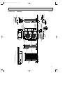
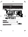
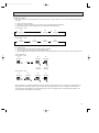
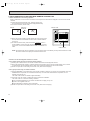
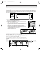
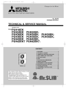
SPLIT-TYPE,HEAT PUMP AIR CONDITIONERS
No. OC120
TECHNICAL & SERVICE MANUAL
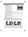
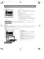
Series PKH Wall Mounted
<Indoor unit>
PKH18FK
PKH24FK
PKH30FK
PKH36FK
/
/
/
/
PUH18EK
PUH24EK
PUH30EK
PUH36EK
CONTENTS
1. FEATURES ···········································2
2. SPECIFICATIONS·································5
3. DATA ·····················································6
4. OUTLINES AND DIMENSIONS··········16
5. WIRING DIAGRAM·····························22
6. REFRIGERANT SYSTEM DIAGRAM ······25
7. OPERATION FLOW-CHART ··············26
8. MICROPROCESSOR CONTROL·······30
9. TROUBLESHOOTING ························51
10. SYSTEM CONTROL ···························59
11. DISASSEMBLY INSTRUCTIONS ·······64
12. PARTS LIST········································71
13. OPTIONAL PARTS ·····························83
Indoor unit
-CENTRALLY CONTROLLEDSTAND BY
DEFROST ON
CHECK DRY
COOL
HEAT
CHECK
SET TEMP
TIMER OFF
AUTO STOP
AUTO START
F
HR
LOW HIGH
F
AUTO RETURN
CHECK TEST RUN
POWER
HEAT
AUTO
SET
WARMER
TEMPERATURE
TIMER
MODE
ON/OFF
COOL/DRY
COOLER
HOURS
FAN SPEED LOW/HIOGH
AIR
UP/DOWN SWING STOP
DISCHARGE
CHECK
TEST RUN
MITSUBISHI ELECTRIC
IFIED TO ARI A
RT
SC
CE
O
AIR
-CO
Y
EQ
UIP MENT
IFI
NS
C
IO
AIR ATIO N SE CT 10
S TA N DARD 2
O
CE
RT
F
UNIT
AR
R
•
G WITH
YIN
PL
M
NING
ITIO
ND
MANUFAC
TU
RE
REMOTE CONTROLLER
•
Models
L IS E D
T
R
The Slim Line.
From Mitsubishi Electric.
OC120--1.qxp
1
24/6/97 12:20 AM
Page 2
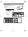
FEATURES
-CENTRALLY CONTROLLEDSTAND BY
DEFROST ON
CHECK DRY
COOL
HEAT
CHECK
SET TEMP
TIMER OFF
AUTO STOP
AUTO START
F
HR
LOW HIGH
F
AUTO RETURN
CHECK TEST RUN
ON/OFF
POWER
HEAT
AUTO
COOL/DRY
SET
WARMER
TEMPERATURE
TIMER
MODE
COOLER
HOURS
FAN SPEED LOW/HIOGH
AIR
UP/DOWN SWING STOP
DISCHARGE
CHECK
TEST RUN
MITSUBISHI ELECTRIC
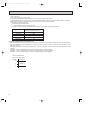
Indoor unit
Remote controller
Models
Cooling capacity / Heating capacity
PKH18FK
PKH24FK
PKH30FK
PKH36FK
18,000
24,000
30,000
34,200
/
/
/
/
18,600
25,000
33,000
38,000
[25,100]
[31,500]
[40,500]
[45,500]
Btu/h
Btu/h
Btu/h
Btu/h
PUH24EK
Outdoor unit
SEER
11.1
10.2
10.6
10.5
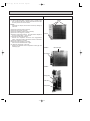
1. COMPACT DESIGN
The PK series models have been downsized and now require such minimal wall space that they can even be installed
above windows. For the PKH18/24FK, 13in of wall space between the ceiling and the window allows “above window”
installation (14.5in for the PKH30/36FK)
2. A FURTHER REFINEMENT OF COMFORT WITH NOISE SUPPRESSION
Remarkably low-noise operation has been achieved through the development of a “near-silent” fan and a design which
minimizes airflow resistance.
3. AUTO FLAP SHUTTER
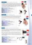
With a simple flick of the OFF switch the air outlet can be closed off with a shutter. The shutter also functions as a flap
during operation to adjust the air flow angle, with “Auto Angle 1” securing a comfortable air flow.
4. INSTALLATION : FAST AND ENDLESSLY ADAPTABLE
(1) External piping
An external piping connection of 24in and a very light body promote trouble-free installation for PKH18FK.
(2) Multi-directional piping
Multi directional drain and refrigerant piping rodically improves flexibility in selecting installation layouts. PKH18FK drain
piping can be installed in 5 directions, while PKH30/36FK models boast refrigerant piping in 4 directions and drain piping
in 2 directions.
(3) Back plate installation guide
The back plate installation guide gives clear instructions on installation positions. The enlarged back plate secures the
unit firmly to the wall, while the support piece which lifts the unit makes left side piping work much easier.
(4) Front power supply box
The front power supply box allows electrical wiring work to be performed easily even after the indoor unit has been fully
installed. All the screws for the indoor unit can be tightened from the front side thus ensuring smooth installation.
(only for PKH18/24FK)
(5) Easily removable filter
The presence of thumbscrews on the filters means that the filters can be quickly and smoothly removed.
(only for PKH30/36FK)
2
OC120--1.qxp
24/6/97 12:21 AM
Page 3
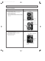
5. ADVANCED MICROPROCESSOR
(1) Easy to Use Microprocessor
1) Ultra-Thin Remote Controller
The streamlined, square controller is designed to
blend with any kind of interior and the adoption of
a sophisticated microprocessor allows you to
carry out a wide range of operations easily.
2) Ultra-Thin Remote Controller
Units operation mode, set temperature, room temperature, timer setting, fan speed, louver operation, and air flow direction are displayed on the
remote controller with the easily understood visual
Liquid Crystal Display (LCD).
3) Convenient 24-Hour ON-OFF Timer
The timer allows Mr.SLIM to be switched on or
off automatically at the time is shown on the LCD.
-CENTRALLY CONTROLLEDSTAND BY
DEFROST ON
POWER
CHECK DRY
COOL
HEAT
HEAT
CHECK
SET TEMP
F
TIMER OFF
AUTO STOP
AUTO START
SET
WARMER
TEMPERATURE
TIMER
HR
LOW HIGH
AUTO
ON/OFF
COOL/DRY
COOLER
MODE
HOURS
FAN SPEED LOW/HIOGH
AIR
UP/DOWN SWING STOP
DISCHARGE
F
AUTO RETURN
CHECK TEST RUN
CHECK
TEST RUN
MITSUBISHI ELECTRIC
4) Self-Diagnostic Feature Indicates Instantly
In the rare case when a problem occurs, the unit stops operating and the set temperature indicator changes to the
self-diagnostic indicator, indicating the location of the fault.
If the check switch is pressed twice, the unit stops operating and the check mode is initiated. The cause of the most
recent problem stored in the memory is displayed on the LCD. This is extremely useful for maintenance purposes.
5) Useful Memory Feature for Storing Instructions
The previous set value is memorized so that constant temperature control can be obtained. This is convenient when,
for example, a power failure occurs.
(2) Non-polar Two-Wire Remote Controller Cables
The non-polar, two-wire type remote controller cable is slim, installation is simple and troublefree. Remote controller
wire can be extended up to 550 yards.
(3) Automatic Cooling / Heating Changeover Operation
An automatic cooling and heating changeover operation system is provided to ensure easy control and year-round air
conditioning.
Once the desired temperature is set, unit operation is switched automatically between cooling and heating, in
accordance with the room temperatures as low as 23oF.
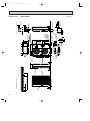
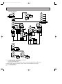
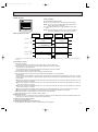
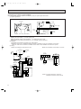
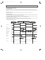
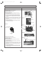
6. REDI-CHARGED REFRIGERANT SYSTEM
PRE-CHARGE REFRIGERANT REQUIRED FOR MAXIMUM PIPING LENGTH AT
SHIPMENT. PREVENTING TROUBLES DUE TO SHORTAGE OF REFRIGERANT.
The unique refrigerant circuit and a large accumulator always controls the refrigerant to its optimum condition regardless of
the length of 164ft maximum or 25ft minimum. The additional refrigerant charging work at the field which often caused
uncertain problems heretofore is completely eliminated. This unique system serves to improve the quality of work and
reliability, and also helps to speed up the installation work.
Indoor unit
Outdoor unit
Indoor unit
Outdoor unit
4•way
valve
Indoor
heat
exchanger
Capillary
tubes for
cooling
Restrictor
valve
4•way
valve
Indoor
heat
exchanger
Outdoor
heat
exchanger
Accumulator
Compressor
Liquid section
of piping
HIgh-pressure
liquid
retrigerant
Capillary
tubes for
heating
Capillary tubes
for heating
Restrictor valve
Restrictor
valve
Outdoor
heat
exchanger
Accumulator
Compressor
Liquid section
of piping
Low-pressure
two-phase
retrigerant
Capillary tubes
for cooling
Restrictor valve
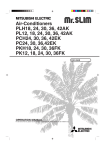
With normal circulation systems, a high-pressure refrigerant, condensed for cooling by the outdoor heat exacanger, is
reduced in pressure by capillary tubes in the indoor unit after passing through the restrictor valve in the outdoor unit (see
Figure 1). With the new circulation system, the direction of the restrictor valve is reversed as shown in Figure 2, and the
condensed high pressure refrigerant is reduced in pressure by the capacity tubes in the outdoor unit. This results in a “twophase refrigerant” of reduced pressure in the liquid section of the piping, The density of this two-phase refrigerant is 1/3~
1/2 of that of the high pressure liquid refrigerant, and thus is required in smaller amounts (see Figures 1 and 2). As a result,
the length of the piping can be extended further, and the effects of height differences are reduced. These new circulation
system are also equipped with a large accumulator which allows the refrigerant required for the 100ft piping length to be
enclosed in the outdoor unit. The result is an air conditioner that requires no charging unless piping is extended beyond
100ft.
3
OC120--1.qxp
24/6/97 12:21 AM
Page 4
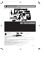
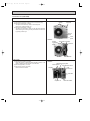
7. HIGH RELIABILITY AND EASY SERVICING
In addition to the self-diagnostic function, units are also equipped with a 3-minute time delay mechanism (cooling), an auto
restart function, an emergency operation function, a test run switch, etc., to assure high reliability and easy servicing.
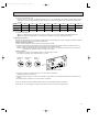
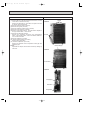
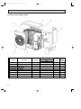
8. FOUR-WAY PIPING ACCESS MAKES
INSTALLATION LAYOUT EASY
Piping on the outdoor unit may be connected from either of
four directions: front, rear, side or beneath the base.
This easy-access design makes it possible to install a
number of units in a compact arrangement at a single site.
The outdoor unit allows for unheard-of flexibility in
detemining a piping layout, thus greatly simplifying
installation.
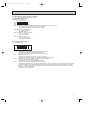
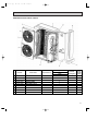
9. FRONT-ACCESS FACILITATES
MAINTENANCE
The outdoor unit has been designed with a frontaccess
service panel that allows easy access to all maintenance
point, regardless of the installation layout. What’s more, this
front panel may be removed by loosening only two screws.
It all adds up to greatly simplified maintenance work.
10. NITROGEN GAS IS CHARGED TO
INDOOR UNIT
Indoor unit and refrigerant pipes are charged with nitrogen
gas (N2) instead of R-22 before shipment from the
factory.
4
Red
Front
Base
Right
OC120--1.qxp
24/6/97 12:21 AM
2
Page 5
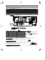
SPECIFICATIONS
MODELS : PKH18/24/30/36FK
Model
PKH18FK
PKH24FK
PKH30FK
PKH36FK
18,000
18,600[24,100/25,100]
10,700[16,200/17,200]
5.3
1.79
1.56[3.16/3.46]
1.34[2.94/3.24]
10.1
11.1
7.2
3.5
2.3
PKH18FK
24,000
25,000[30,500/31,500]
14,700[20,200/21,200]
7.0
2.36
2.37[3.97/4.27]
1.92[3.52/3.82]
10.2
10.2
6.8
3.1
2.2
PKH24FK
Munsell 3.4Y 7.7/0.8
208/230,1,60
15
12
0.5
7.6/8.4[1.6/1.9]
710-530
640-480
43-35
1
30,000
33,000[39,100/40,500]
19,000[25,100/26,500]
9.1
3.12
3.02[4.82/5.22]
2.48[4.28/4.68]
9.6
10.6
7.1
3.2
2.2
PKH30FK
34,200
38,000[44,100/45,500]
19,600[25,700/27,100]
10.5
3.44
3.54[5.34/5.74]
2.65[4.45/4.85]
9.9
10.5
6.9
3.1
2.2
PKH36FK
15
13
0.6
8.7/9.6[1.8/2.2]
990-780
890-700
46-41
1
13
0.6
8.7/9.6[1.8/2.2]
990-780
890-700
46-41
1
Item
Capacity
Cooling *1
Heating *1
Heating *2
Moisture removal
Power
Consomption
EER
SEER
HSPF
Cooling *1
Heating *1
Heating *2
*1
Btu/h
Btu/h
Btu/h
Pints/h
kW
kW
kW
*1
*2
COP
INDOOR UNIT MODELS
External finish
Power supply
V,phase,Hz
Max.fuse size (time dalay)
A
Min.ampacity
A
Fan motor
F.L.A.
Booster heater
A(kW)
Dry
CFM
Airflow Hi-Lo
Wet
CFM
Sound level Hi-Lo
dB(A)
Cond. drain connection OD
W
in.
Dimensions
D
in.
H
in.
Weight
in.
OUTDOOR UNIT MODELS
lb
External finish
Power supply
Max.fuse size (time dalay)
V,phase,Hz
Min.ampacity
A
Fan motor
A
Model (type) F.L.A.
Compressor
R.L.A.
Crankcase heater
L.R.A.
Refrigerant control
A(W)
Defrost method
Sound level
dB(A)
W
Dimensions
D
in.
H
in.
Weight
in.
REMOTE CONTROLLER
lb
Control voltage (by built-in transformer)
REFRIGERANT PIPING
Liquid
Pipe size
Gas
in.
Connection
Indoors
in.
method
Outdoors
Between the indoor
Height difference ft
& outdoor units
Piping length
ft
15
12
0.5
7.6/8.4[1.6/1.9]
710-530
640-480
43-35
1
55-1/8
66-5/32
9-1/4
13-3/8
57
PUH18EK
57
PUH24EK
Munsell 5Y 7/1
208/230,1,60
20
16
0.65+0.65
NH33NBD
11.5
54
0.16/0.17[33/39]
Capillary tube
Reverse cycle
55
20
16
0.75
RH247NAB
12
37
0.11/0.12[23/28]
53
34-1/4
11-5/8
33-1/2
131
66
PHU30EK
66
PUH36EK
30
20
0.75+0.75
NH41NAD
14.0
73
0.16/0.17[33/39]
30
22
0.75+0.75
NH47ND
17.5
87
0.16/0.17[33/39]
55
38-3/16
13-9/16
49-9/16
245
38-3/16
13-9/16
49-9/16
246
49-9/16
202
With indoor unit
Indoor unit-remote controller:DC12V. Indoor unit-outdoor unit:DC12V
Not supplied(optional parts)
1/2
3/8
3/4
5/8
Flared
Flared
130
164
130
164
1/2
3/4
164
164
NOTES : *1.Rating conditions (cooling)-indoor : 80˚FDB,67˚FWB outdoor : 95˚FDB,75˚FWB.
(heating)-indoor : 70˚FDB,60˚FWB outdoor : 47˚FDB,43˚FWB.
*2.Rating conditions (heating)-indoor : 70˚FDB,60˚FWB outdoor : 17˚FDB,15˚FWB.
*3.Heating capacity and power consumption in [ ] includes heater operation at 208/230V.
Operating range
Cooling
Heating
Maximum
Minimum
Maximum
Minimum
Indoor intake air temperature
Outdoor intake air temperature
95˚FDB,71˚FWB
67˚FDB,57˚FWB
80˚FDB,67˚FWB
70˚FDB,68˚FWB
115˚FDB
0˚FDB
75˚FDB,65˚FWB
17˚FDB,15˚FWB
5
OC120--1.qxp
3
24/6/97 12:21 AM
Page 6
DATA
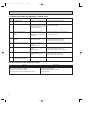
MODELS : PKH18/24/30/36FK
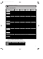
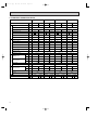
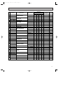
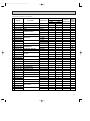
1. PERFORMANS DATA
1) COOLING CAPACITY
Models
Models
Airflow
(CFM)
B.F
Outdoor intake air DB temperature(˚F)
75
85
95
115
TC
SHC
TPC
TC
SHC
TPC
TC
SHC
TPC
TC
SHC
TPC
TC
SHC
TPC
71
21.0
14.4
1.56
20.2
13.9
1.69
19.4
13.3
1.84
18.5
12.7
1.99
17.6
12.1
2.15
67
19.5
16.0
1.52
18.8
15.4
1.65
18.0
14.8
1.79
17.1
14.0
1.93
16.3
13.4
2.07
63
18.2
17.4
1.49
17.5
16.7
1.61
16.8
16.0
1.74
15.9
15.2
1.88
15.1
14.4
2.01
DB 75¡F (50%RH) 62.5
18.1
15.5
1.49
17.4
14.9
1.61
16.6
14.3
1.74
15.8
13.6
1.87
15.0
12.9
2.00
DB 72¡F (50%RH)
60
17.2
15.1
1.47
16.6
14.5
1.58
15.8
13.8
1.70
15.0
13.1
1.84
14.2
12.4
1.96
DB 70¡F (50%RH)
59
16.8
14.5
1.46
16.2
14.0
1.57
15.5
13.4
1.69
14.6
12.6
1.83
13.9
12.0
1.94
71
27.9
16.1
2.05
26.9
15.5
2.23
25.8
14.9
2.43
24.6
14.2
2.63
23.4
13.5
2.84
67
26.1
18.5
2.01
25.1
17.8
2.18
24.0
17.0
2.36
22.9
16.3
2.55
21.7
15.4
2.73
63
24.3
20.5
1.97
23.4
19.7
2.12
22.4
18.9
2.30
21.3
18.0
2.47
20.1
17.0
2.65
DB 75¡F (50%RH) 62.5
24.1
18.0
1.96
23.2
17.4
2.12
22.2
16.6
2.29
21.1
15.8
2.47
19.9
14.9
2.64
DB 72¡F (50%RH)
60
23.0
17.6
1.94
22.1
16.9
2.09
21.1
16.2
2.25
20.1
15.4
2.41
18.9
14.5
2.58
DB 70¡F (50%RH)
59
22.5
17.0
1.93
21.7
16.4
2.07
20.7
15.6
2.24
19.7
14.9
2.39
18.5
14.0
2.56
71
34.9
21.5
2.72
33.7
20.8
2.95
32.3
19.9
3.21
30.8
19.0
3.48
29.3
18.1
3.75
67
32.6
24.5
2.66
31.4
23.6
2.88
30.0
22.5
3.12
28.6
21.5
3.37
27.1
20.3
3.61
63
710
0.16
PKH18FK
710
0.16
PKH24FK
990
0.15
PKH30FK
30.4
26.9
2.60
29.2
25.8
2.81
27.9
24.6
3.04
26.6
23.5
3.27
25.1
22.2
3.50
DB 75¡F (50%RH) 62.5
30.2
23.8
2.59
29.0
22.9
2.80
27.7
21.9
3.03
26.3
20.7
3.26
24.9
19.6
3.49
DB 72¡F (50%RH)
60
28.8
23.2
2.57
27.6
22.2
2.77
26.3
21.2
2.99
24.9
20.1
3.21
23.5
18.9
3.43
DB 70¡F (50%RH)
59
28.2
22.4
2.56
27.0
21.5
2.76
25.7
20.4
2.98
24.4
19.4
3.19
22.9
18.2
3.41
71
39.8
23.0
3.00
38.4
22.1
3.25
36.8
21.2
3.54
35.1
20.2
3.83
33.4
19.3
4.13
67
37.1
26.3
2.93
35.7
25.3
3.17
34.2
24.3
3.44
32.6
23.1
3.71
30.9
21.9
3.98
63
34.7
29.3
2.87
33.3
28.1
3.10
31.9
26.9
3.35
30.3
25.6
3.61
28.7
24.2
3.86
DB 75¡F (50%RH) 62.5
34.4
25.8
2.86
33.1
24.8
3.09
31.6
23.7
3.34
30.0
22.5
3.59
28.4
21.3
3.85
DB 72¡F (50%RH)
60
32.8
25.1
2.82
31.5
24.1
3.04
30.1
23.0
3.28
28.5
21.8
3.52
26.9
20.6
3.76
DB 70¡F (50%RH)
59
32.2
24.3
2.81
30.8
23.2
3.03
29.5
22.3
3.26
27.9
21.0
3.50
26.4
19.9
3.73
990
0.14
PKH36FK
Notes 1. B.F. : Bypass Factor, IWB : Intake air wet-bulb temperature
TC : Total Capacity (x103 Btu/h), SHC : Sensible Heat Capacity (x103 Btu/h)
TPC : Total Power Consumption (kW)
2. SHC is based on 80˚FDB of indoor intake air temperature.
3. Cooling capacity correction factors and Refrigerant piping length (one way) range.
Refrigerant piping length (one way)
MODEL
6
105
IWB
(˚F)
25ft
40ft
55ft
70ft
85ft
100ft
115ft
130ft
PKH18FK
1.0
0.992
0.983
0.978
0.966
0.959
0.950
0.945
PKH24FK
1.0
0.981
0.968
0.952
0.940
0.925
0.913
PKH30FK
1.0
0.981
0.968
0.952
0.940
0.925
0.913
PKH36FK
1.0
0.981
0.968
0.952
0.940
0.925
0.913
150ft
164ft
0.900
0.886
0.874
0.900
0.886
0.874
0.900
0.886
0.874
OC120--1.qxp
24/6/97 12:21 AM
Page 7
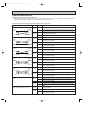
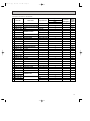
2) HEATING CAPACITY
Models
Models
PKH18FK
PKH24FK
PKH30FK
PKH36FK
Airflow
(CFM)
710
710
990
990
Auxiliary heater
208V
230V
Outdoor intake air WB temperature(˚F)
15
25
35
45
55
65
IWB
(˚F)
CA
PC
CA
PC
CA
PC
CA
PC
CA
PC
CA
PC
CA
PC
75
12.1
1.20
14.1
1.34
16.3
1.49
18.7
1.65
21.4
1.83
23.7
1.99
5.5
1.6
70
12.4
1.16
14.4
1.29
16.7
1.44
19.1
1.59
21.8
1.76
24.1
1.91
65
12.7
1.11
14.7
1.24
17.0
1.38
19.5
1.53
22.2
1.69
24.5
1.83
6.5
1.9
75
16.3
1.82
18.9
2.03
21.9
2.27
25.2
2.51
28.8
2.77
32.8
3.01
5.5
1.6
70
16.6
1.76
19.4
1.96
22.4
2.19
25.7
2.42
29.3
2.67
33.3
2.90
65
17.0
1.69
19.8
1.89
22.9
2.10
26.2
2.32
29.9
2.56
33.9
2.78
6.5
1.9
75
21.5
2.32
25.0
2.59
28.9
2.89
33.2
3.20
38.0
3.53
43.2
3.86
6.1
1.8
70
21.9
2.24
25.5
2.50
29.6
2.78
33.9
3.08
38.6
3.40
43.7
3.72
7.5
2.2
65
22.5
2.15
26.1
2.40
30.2
2.68
34.6
2.96
39.4
3.26
44.6
3.56
75
24.7
2.71
28.7
3.04
33.3
3.39
38.2
3.75
43.7
4.14
49.6
4.49
6.1
1.8
70
25.3
2.62
29.4
2.93
34.1
3.26
39.0
3.61
44.5
3.98
50.4
4.28
7.5
2.2
65
25.9
2.53
30.1
2.82
34.8
3.14
39.9
3.47
45.4
3.83
51.3
4.14
Notes 1. IDB : Intake air dry-bulb temperature
CA : Capacity (x103 Btu/h), PC : Power Consumption (kW)
2. When booster heater is "on", total capacity and total power consnmption should be added the figures described in
booster heater colnmn.
•Booster heater ON : When the set temperature is higher than the room temperature by more than 5.4 deg.
•Booster heater OFF : When the set temperature is higher than the room temperature by less than 3.6 deg.
3. Heating capacity correction factors.
Refrigerant piping length (one way)
Models
Less than 100ft
100~130ft
130~164ft
PKH18FK
1.00
0.995
0.990
PKH24FK
1.00
0.995
0.990
PKH30FK
1.00
0.995
0.990
PKH36FK
1.00
0.995
0.990
7
OC120--1.qxp
24/6/97 12:21 AM
Page 8
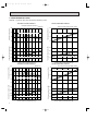
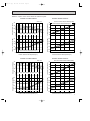
2. PERFORMANCE CURVE
NOTES : A point on the curve shows the reference point.
PKH18FK COOLING CAPACITY
PKH18FK HEATING CAPACITY
Total capacity (x10 3 Btu/h)
24
SHF=0.82
Indoor intake air WB temperature ( F)
18
71
67
63
Total capacity (x10 3 Btu/h)
PKH18FK COOLING CAPACITY
30
12
1.5
Indoor intake air WB temperature ( F)
1.0
023
32 35
45
55
65(67) 75
85
95
105
Total power consumption (kW)
71
67
63
2.0
Indoor intake air DB temperature ( F)
18
2.5
75
70
65
2.0
1.5
Indoor intake air DB temperature ( F)
1.0
15
115
Outdoor intake air DB temperature ( F)
Indoor intake air WB temperature ( F)
71
67
63
18
Total capacity (x10 3 Btu/h)
Total capacity (x10 3 Btu/h)
30
24
12
45
55
65
Does not include booster heater (1.9kW)
35
Indoor intake air DB temperature ( F)
30
65
70
75
24
18
12
3.0
71
67
63
2.5
2.0
Indoor intake air WB temperature ( F)
1.5
023
32 35
45
55
65(67) 75
85
95 105
Outdoor intake air DB temperature ( F)
115
Total power consumption (kW)
Total power consumption (kW)
35
PKH24FK HEATING CAPACITY
SHF=0.71V
36
25
Outdoor intake air WB temperature ( F)
PKH24FK COOLING CAPACITY
8
65
70
75
24
12
2.5
Total power consumption (kW)
Does not include booster heater (1.9kW)
30
3.0
75
70
65
2.5
2.0
Indoor intake air DB temperature ( F)
1.5
15
25
35
45
55
Outdoor intake air WB temperature ( F)
65
OC120--1.qxp
24/6/97 12:21 AM
Page 9
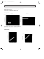
NOTES : A point on the curve shows the reference point.
PKH30FK COOLING CAPACITY
SHF=0.75
36
30
71
67
63
24
indoor intake air WB temperature(¡F)
4.0
71
67
63
3.5
3.0
2.5
2.0
indoor intake air WB temperature(¡F)
0 23 32 35 45
55 65 (67) 75
85
95 105
Outdoor intake air DB temperature(¡F)
Total capacity(x10 3 Btu/h)
48
Total power consumption(kW)
Total power consumption(kW)
Total capacity(x10 3 Btu/h)
42
PKH30FK HEATING CAPACITY
115
42
36
30
24
18
4.0
75
70
65
3.5
3.0
2.5
2.0
indoor intake air DB temperature(¡F)
1.5
15
25
35
45
55
65
Outdoor intake air WB temperature(¡F)
PKH36FK HEATING CAPACITY
SHF=0.71
36
71
67
63
30
24
indoor intake air WB temperature(¡F)
4.5
71
67
63
4.0
3.5
3.0
2.5
indoor intake air WB temperature(¡F)
0 23 32 35 45
55 65 (67) 75
85
95 105
Outdoor intake air DB temperature(¡F)
115
Total capacity(x10 3 Btu/h)
54
Total power consumption(kW)
Total capacity(x10 3 Btu/h)
Total power consumption(kW)
65
70
75
indoor intake air DB temperature(¡F)
PKH36FK COOLING CAPACITY
42
Does not include booster heater(2.2kW)
Does not include booster heater(2.2kW)
indoor intake air DB temperature(¡F)
48
65
70
75
32
36
30
24
75
70
65
4.5
4.0
3.5
3.0
2.5
indoor intake air DB temperature(¡F)
2.0
15
25
35
45
55
65
Outdoor intake air WB temperature(¡F)
9
OC120--1.qxp
24/6/97 12:21 AM
Page 10
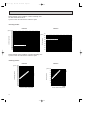
3. CONDENSING PRESSURE AND SUCTION PRESSURE
Data is based on the condition of indoor humidity 50%.
Air flow should be set at HI.
A point on the curve shows the reference point.
<Cooling mode>
PKH18FK
86
80
75
70 (psi.G) 100
86
80
75
70
90
Suction pressure
Condensing pressure
(psi.G) 350
340
330
320
310
300
290
280
270
260
250
240
230
220
210
200
190
180
170
160
150
PKH18FK
80
Indoor DB temperature( F)
70
60
50
40
Indoor DB
temperature( F)
30
30
40
50
60
70
80
90
Outdoor ambient temperature
100
110
DB( F)
20
30
40
50
60
70
80
90
Outdoor ambient temperature
100
Data is based on the condition of outdoor humidity 75%.
A point on the curve shows the reference point.
<Heating mode>
PKH18FK
10
80
F)
(psi.G)
75
70
65
pe
r
at
ur
e(
70
50
40
DB
te
m
60
In
do
or
Suction pressure
Condensing pressure
(psi.G) 350
340
330
320
310
300
290
280
270
260
250
)
240
(F
e
r
230
tu
75
ra
220
70
pe
m
210
65
te
B
200
D
r
190
oo
180 Ind
170
160
150
20 25 30 35 40 45 50 55 60 65 70
DB( F)
Outdoor ambient temperature
PKH18FK
30
20
10
20 25 30 35 40 45 50 55 60 65 70
DB( F)
Outdoor ambient temperature
110
DB( F)
OC120--1.qxp
24/6/97 12:21 AM
Page 11
Data is based on the condition of indoor humidity 50%.
Air flow should be set at HI.
A point on the curve shows the reference point.
<Cooling mode>
PKH24FK
360
(psi.G) 350
340
330
320
310
300
290
280
270
260
250
240
230
220
210
200
190
180
170
160
PKH24FK
Suction pressure
Condensing pressure
86
80 (psi.G) 100
75
70
90
Indoor DB
temperature( F)
80
86
80
75
70
Indoor DB temperature( F)
70
60
50
40
30
30
40
50
60
70
80
90
Outdoor ambient temperature
100
110
DB( F)
20
30
40
50
60
70
80
90
Outdoor ambient temperature
100
110
DB( F)
Data is based on the condition of outdoor humidity 75%.
A point on the curve shows the reference point.
<Heating mode>
PKH24FK
e(
F)
(psi.G) 80
75
70
65
pe
ra
tu
r
70
te
m
60
40
do
or
DB
50
In
Suction pressure
Condensing pressure
(psi.G) 350
340
330
320
310
300
290
F)
280
e(
ur
t
270
ra
75
pe
260
m
70
te
250
B
65
D
240
or
o
230 nd
220 I
210
200
190
180
170
160
150
20 25 30 35 40 45 50 55 60 65 70
DB( F)
Outdoor ambient temperature
PKH24FK
30
20
10
20 25 30 35 40 45 50 55 60 65 70
DB( F)
Outdoor ambient temperature
11
OC120--1.qxp
24/6/97 12:21 AM
Page 12
Data is based on the condition of indoor humidity 50%.
Air flow should be set at HI.
A point on the curve shows the reference point.
<Cooling mode>
PKH30FK
PKH30FK
86
80 (psi.G) 110
75
100
70
Suction pressure
Condensing pressure
(psi.G) 350
340
330
320
310
300
290
280
270
260
250
240
230
220
210
200
190
180
170
160
150
Indoor DB temperature( F)
86
80
75
70
90
Indoor DB temperature( F)
80
70
60
50
40
30
40
50
60
70
80
90
Outdoor ambient temperature
100
110
DB( F)
30
30
40
50
60
70
80
90
Outdoor ambient temperature
100
Data is based on the condition of outdoor humidity 75%.
A point on the curve shows the reference point.
<Heating mode>
PKH30FK
12
e(
F
)
(psi.G) 80
at
ur
70
te
In
do
or
DB
50
40
75
70
65
m
pe
r
60
Suction pressure
Condensing pressure
(psi.G) 340
330
320
310
300
290
280
F)
e(
270
r
tu
260
ra
75
pe
250
70
m
te
240
65
B
D
230
or
o
220
d
210 In
200
190
180
170
160
150
140
20 25 30 35 40 45 50 55 60 65 70
DB( F)
Outdoor ambient temperature
PKH30FK
30
20
10
20 25 30 35 40 45 50 55 60 65 70
DB( F)
Outdoor ambient temperature
110
DB( F)
OC120--1.qxp
24/6/97 12:21 AM
Page 13
Data is based on the condition of indoor humidity 50%.
Air flow should be set at HI.
A point on the curve shows the reference point.
<Cooling mode>
PKH36FK
Suction pressure
86
80 (psi.G)
90
75
70
80
Condensing pressure
(psi.G) 350
340
330
320
310
300
290
280
270
260
250
240
230
220
210
200
190
180
170
160
150
PKH36FK
Indoor DB temperature( F)
70
86
80
75
70
Indoor DB temperature( F)
60
50
40
30
20
30
40
50
60
70
80
90
Outdoor ambient temperature
100
110
DB( F)
30
40
50
60
70
80
90
Outdoor ambient temperature
100
110
DB( F)
Data is based on the condition of outdoor humidity 75%.
A point on the curve shows the reference point.
<Heating mode>
PKH36FK
(F
)
(psi.G) 80
pe
ra
tu
re
70
In
do
or
D
B
50
40
75
70
65
te
m
60
Suction pressure
Condensing pressure
(psi.G) 390
380
370
360
350
340
330
320
310
F)
300
e(
r
290
tu
75
ra
280
70
pe
m
270
65
te
260
DB
r
250
oo
240 Ind
230
220
210
200
190
20 25 30 35 40 45 50 55 60 65 70
DB( F)
Outdoor ambient temperature
PKH36FK
30
20
10
20 25 30 35 40 45 50 55 60 65 70
DB( F)
Outdoor ambient temperature
13
OC120--1.qxp
24/6/97 12:21 AM
Page 14
4. STANDARD OPERATION DATA
Models
PKH18FK
Refrigerant circuit
Electrical circuit
Item
Indoor side
Outdoor side
PKH36FK
Cooling
Heating
Cooling
Heating
Cooling
Heating
Cooling
Heating
Voltage
V
208/230
208/230
208/230
208/230
208/230
208/230
208/230
208/230
Frequency
Hz
Total input
kW
1.79
1.56
2.36
2.37
3.12
3.02
3.44
3.54
Indoor fan current
A
0.5
0.5
0.5
0.5
0.5
0.5
0.5
0.5
Booster heater current
A
Outdoor fan current
A
0.75
0.75
0.65+0.65
0.65+0.65
0.75+0.75
0.75+0.75
0.75+0.75
0.75+0.75
Comp. current
A
7.4/6.9
6.1/5.9
9.3/8.7
9.5/8.7
12.6/11.8
12.2/11.4
14.3/13.2
14.7/13.7
Condensing pressure
psi.G
255
202
240
243
245
236
243
263
Suction pressure
psi.G
81
61
75
63
80
60
74
60
Discharge temperature
˚F
182
126
158
149
158
159
160
170
Condensing temperature
˚F
118
102
115
115
115
113
115
120
Suction temperature
˚F
66
34
46
35
49
32
45
33
Comp.shell bottom temperature
˚F
171
111
141
126
138
130
142
148
Ref. pipe length
ft
Intake
air temperature
Discharge
air temperature
60
60
60
7.6/8.4
60
7.6/8.4
7.6/8.4
25
5 lbs 8 oz
8.7/9.6
25
9 lbs 15 oz
25
10 lbs 2 oz
10 lbs 9 oz
DB
˚F
80
70
80
70
80
70
80
70
WB
˚F
67
60
67
60
67
60
67
60
DB
˚F
61
96
58
105
59
103
58
109
WB
˚F
59
68
56
70
58
70
56
71
Fan speed
r.p.m.
1,490
1,490
1,490
1,490
Airflow (High)
CFM
710
710
990
990
Intake
air temperature
Fan speed upper/lower
Airflow
Capacity
14
PKH30FK
Unit
Refrigerant charge
SHF
PKH24FK
DB
˚F
95
47
95
47
95
47
95
47
WB
˚F
75
43
75
43
75
43
75
43
r.p.m.
790
CFM
Btu/h
750/750
1,590
18,000
0.82
760/760
3,170
18,600
24,000
0.71
760/760
3,350
25,000
30,000
0.75
3,350
33,000
34,100
0.71
38,000
OC120--1.qxp
24/6/97 12:21 AM
Page 15
5. OPERATING RANGE
1) POWER SUPPLY
Min.
198V
1 Phase 60Hz 208/230V
Guaranteed voltage range
208V
Max.
253V
230V
2) OPERATION
Air intake temperature
Indoor
Outdoor
Function
Condition
DB(˚F)
WB(˚F)
DB(˚F)
WB(˚F)
Standard temperature
80
67
95
75
Maximum temperature
95
71
115
—
MInimum temperature
67
57
23
—
Maximum humidity
80
75
80
75
Standard temperature
70
60
47
43
Maximum temperature
80
67
75
65
MInimum temperature
70
60
17
15
Cooling
Heating
6. OUTLET AIR SPEED AND COVERAGE RANGE
Model
Airflow
(CFM)
Air speed
(ft/sec)
Coverage
range(ft)
PKH18FK
710
16.1
41
PKH24FK
710
16.1
41
PKH30FK
990
17.7
50
PKH36FK
990
17.7
50
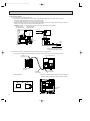
The air coverage range is the value up to the position
where the air speed is 0.8ft/sec. when air is blown out
horizontally from the unit at the High notch position.
The coverage range should be used only as a general
guideline since it varies according to the size of the
room and furniture installed inside the room.
7. ADDITIONAL REFRIGERANT CHARGE (R-22(oz))
Refrigerant piping length (one way)
Outdoor unit
precharged
(up to 100ft)
25ft
40ft
55ft
70ft
85ft
100ft
115ft
130ft
PKH18FK
5 lbs 8 oz
0
0
0
0
0
0
2
4
PKH24FK
9 lbs 15 oz
0
0
0
0
0
0
2
PKH30FK
10 lbs 2 oz
0
0
0
0
0
0
PKH36FK
10 lbs 9 oz
0
0
0
0
0
0
Model
150ft
164ft
4
7
9
5
10
16
20
5
10
16
20
15
3-15/16
5/32 1-17/32
32-{15/32
hole for bolt
66-{1/4 hole for
tapping screw
Wall fixture
1-17/32
B
8-27/32
23/32
3-27/32
1-15/32
2-29/32
A
1-3/16
Knock out hole for piping
1-15/32
2-9/16
7-3/32
Hole for
tapping screw
9-7/16
on left-hand side
12-3/8
2-3/8
55-1/8
20-9/16
Auto vane
Lower side
Drain hose
Air intake
2-15/32
Air outlet
Liquid pipe
Refrigerant pipe. Drain pipe
9-1/4
Right side
Terminal block for control
7-3/4
9-7/16
B
Liquid pipe
Gas pipe
2-5/32
4-23/32 (Gas pipe)
7-7/32 (Liquid pipe)
Change vane (manual)
Under panel
Removable at left-hand
side piping
Knock out hole for under-piping
Air outlet
42-15/16
Front
55-1/8
9-1/4
1-25/32
9-1/4
1-25/32
43-11/16
9-1/4
1-25/32
20-9/16
9-1/4
7-17/32 Rear piping opening
3-19/32
Range for left rear piping opening
11-1/32
24
on right-hand side
11-7/32
3/4
17-29/32
10x3-19/32=(35-13/16)
35-7/16
Drainage range
23/32 Drainage range
Drain hose for 31/32
left-hand side piping
9-21/32
Unit center
1-15/32
13-3/8
Knock out hole for
left piping
Left side
38-31/32
2-9/16
2-29/32
C
1-3/16
A
1-17/32
5/32 3-15/16
Top
Terminal block for power supply
Gas pipe
Terminal block for remote controller
4-1/32
4-3/8
Drain hose
Bolt
19/32
C
Knock out hole for right piping
Refrigerant pipe. Drain pipe
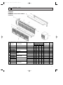
4.1. Indoor Unit
PKH18/24FK
13/32
1-3/16
1-5/32
16
24/6/97 12:21 AM
1-3/18 7-1/4
1-3/16
3-5/32
11-1/32
4
1/2
OC120--1.qxp
Page 16
OUTLINES AND DIMENSIONS
Unit : mm
3-15/16
1-17/32
for bolt
3-27/32
11-5/8
23/32
2-29/32
1-15/32
9-7/16
A
35-7/16
29-17/32
11-1/32
3-19/32
23-7/16
13x3-19/32=(7-3/16)
7-3/32
Range for left rear piping hole
rear piping hole
50
Unit center
Range for left
8-27/32
23/32
Wall fixture
Unit out line
Left hand side
2-9/16
C
1-3/16
Air
outlet
1-3/16
or more
Rear piping hole
12-3/8
3/4
11-7/32
9-21/32
right-hand side
Drainage range on
Drain hose for
left-handside piping
31/32
for left piping
Knock out hole
Left side
5-/15/16 or less
1-5/32
for tapping screw
12- 1/4 hole
7-17/32
9-1/4
9-1/4
Front
27-5/16 Air outlet
9-1/4
1-25/32
louvers(manual)
27-5/16 Air outlet
Lower side
Auto vanes
7-7/32
Refrigerant pipe .Drain pipe
Knock out hole for under-piping
left-hand piping)
Under panel (Removable at
55-1/8
1
Terminal block for powar supply
Terminal block for control
Drain hose
9-1/4
1-25/32
Terminal block for remote controller
53-15/16 Alr Intake
66-5/32
9-1/4
1-25/32
43-11/16 (Drain hose)
1-25/32
Top
2
Knock out hole
for right piping
9-7/16
B
2-5/32(Gas pipe)
4-23/32(Liquid pipe)
19/32
or less
9-1/4
4-3/8
4-1/32
Bolt
Right side
C
3/4F
3-1/2~
>
< 1 Sleeves are availaable
on the market.
3-1/2
4
Through hole
1/2F
Liquid pipe
Gas pipe
Sleeve >
<1
1
2
PKH 30/36FK
41- 15/32 hole
screw
for tapping
1-17/32
1-15/32
B
Knock out hole for wiring
Drainage range on
2-29/32
1-3/16
A
2-9/16
10 or more
1-15/32
Air
intake
10 or more
1-17/32
2 or more
84- 1/4 hole
5/32
3-15/16
5/32
13-3/8
13/32
7-1/4
1-3/16
1-3/16
1-3/16
3-5/32
2-9/32
Front
11-1/32
2-15/32
1/2
1-21/32
24/6/97 12:21 AM
2-3/8
7-3/4
OC120--1.qxp
Page 17
Unit : mm(inch)
17
5-7/16
Handle for
moving
3-3/4
4
For 10 units or less
Rear piping hole
1/2
Rear fresh
air intake
Side air intake
8
40
11-5/8
1
Air intake
Outlet guide
installation hole
20-5/18
1-9/16
Drain hole
Handle for moving
1
2
34-1/4
Drain hole
1/2x7/8 Oval hoies
(standard bolt W3/8(M10)
20-5/8
11-7/8
Air outlet
1/2
1/2
36
Service panel
Ground
terminal
Handie for moving
2-3/8
1/2
R
4
1/
2-9/16
4-3/4
2-3/8
Front right piping holesdetail figures
(refrigerant. drainage
R1
and wiring)
3/
16
Bottom piping hole
Knock out hole for
right piping
Knock out hole
for front piping
(refrigerant. drainage
and wiring)
Refrigerant pipe
(Flared) 3/8
Refrigerant pipe
(Flared) 5/8
Terminal block for power line
Note:Allow adequate
upper clearance.
(for N.E.C)
Service space
1/2
Front opening
Terminal block for indoor and outdoor unit connection
2-U-shaped
notched
holes
1/5/16
4-1/8
7-9/32
9/16
The upper side must be open.
17-3/18
14-1/4
13-7/8
Air intake
1-5/8
7-1/18
11/16
1-9/161-1/16
13
13-7/4
1-3/4
21-3/4
33-9/16
15-7/8
8
4
19-11/16
3-1/8
7-9/32
11/16
16
36
Outdoor Unit-Necessary surrouding clearance
(Concentrated installation)
3/
R1
Knock out holes for
power line 1-1/16
1-3/4
Standard bolt length
4.2. Outdoor Unit
2-1/16
18
24/6/97 12:21 AM
1 max.
OC120--1.qxp
Page 18
PUH18EK
Unit : mm
5-7/16
Handle
formoving
3-3/4
1/2
Rear piping hole
For 10 units or less
12
40
Rear fresh
air intake
Side air intake
1
6
1/4
11-5/8
Air intake
Outlet guide
installation hole
1-9/16
Drain hole
Handle for moving
1
2
23-1/16
13-9/16
34-1/4
Drain hole
2-1/2x7/8 Oval hoies
(standard bolt M10)W3/8(M10)
20-5/8
11-7/8
Air outlet
Air intake
19-11/16
Handie
for moving
Ground
terminal
2-3/8
1/2
2-U-shaped
notched
holes
1/2
R
4
1/
2-9/16
3/8
4-3/4
2-3/8
36
Note:Allow adequate
upper clearance.
(for N.E.C)
Service space
1/2
Front opening
Front right piping holesdetail figures
Knock out hole
for right piping
R1
Bottom
3/
(refrigerant.
16
piping hole drainage and wiring)
Knock out hole
for front piping
(refrigerant. drainage
and wiring)
Refrigerant pipe
(Flared) 3/8F
Refrigerant pipe
(Flared) 5/8F
Terminal block for power line
Terminal block for
indoor and outdoor
unit connection
Service panel
1/9/16
4-1/8
7-9/32
14-1/4
15-7/8
20-5/8
2-3/8
20-5/8
3-1/4
11/16
1-9/161-1/16
13
9/16
15-1/16
2-1/16
49-1/2
7-9/32
37-34
2-1/4
Outdoor Unit - necessary surrounding clearance
3-1/8
The upper side must be open.
11/16
16
12
4
Outdoor Unit-Necessary surrouding clearance
(Concentrated installation)
3/
R1
36
Standard bolt length
Knock out holes for
power line 1-1/16
1-3/4
Outdoor Unit
2-1/16
24/6/97 12:21 AM
1 max.
OC120--1.qxp
Page 19
PUH24EK
Unit : mm
19
3-3/4
Rear piping hole
For 10 units or less
5-7/16
Rear fresh
air intake
Side air intake
7/8
1/4
13-9/16
Outlet guide
installation hole
1-9/16
Drain hole
Handle for moving
1
Air intake
20-5/8
2-3/8
20-5/8
12
40
38-3/16
Drain hole
2-1/2x7/8 Oval hoies
(standard bolt W3/8(M10)
20-5/8
13-7/8
Air outlet
2-3/8
1/2
Bottom
piping hole
2-U-shaped
notched
holes
1/9/16
4-1/8
Handie
for moving
Ground
terminal
1/2
R
4
1/
2-9/16
1/2
4-3/4
2-3/8
36
Note:Allow adequate
upper clearance.
(for N.E.C)
Service space
1/2
Front opening
Front right piping holesdetail figures
Knock out hole
for right piping
R1
3/
(refrigerant.
drainage and wiring) 16
Knock out hole
for front piping
(refrigerant. drainage
and wiring)
Refrigerant pipe
(Flared) 3/8F
Refrigerant pipe
(Flared)
(PUH30/36EK) 3/4
(PUH42EK)7/8F
Terminal block for power line
Terminal block for
indoor and outdoor
unit connection
Service panel
15-7/8
Handle
formoving
1/2
15-1/16
Air intake
7-9/32
49-1/2
6
1-5/16
23-1/16
13-9/16
11/16
1-9/16 1-1/16
14-31/32
9/16
2-1/16
3-1/4
16-1/4
37-3/4
23-5/8
16
7-9/32
Standard bolt length
Knock out holes for
power line 1-1/16
1 max.
The upper side must be open.
11/16
2-1/4
Outdoor Unit - necessary surrounding clearance
3-1/8
12
6
Outdoor Unit-Necessary surrouding clearance
(Concentrated installation)
3/
R1
36
Outdoor Unit
1-3/4
20
24/6/97 12:21 AM
2-1/16
OC120--1.qxp
Page 20
PUH30/36EK
Unit : mm
Remote controller
Page 21
Unit : mm
(PKH series)
3-5/8
POWER —
ON
AUTO DRY
HEAT
COOL
2-3/4
CHECK
SET TEMP
F
TIMER OFF
AUTO STOP
AUTO START
HR
LOW HIGH
AIR SWEEP
F
HEAT
AUTO
SET
WARMER
TEMPERATURE
TIMER
FAN SPEED
MODE
5/8
ON/OFF
COOL/DRY
COOLER\
HOURS
4-1/4
•CENTRALLY CONTROLLED•
S TA N D B Y
DEFROST
3-5/8
LOW/HIGH
4-3/4
24/6/97 12:22 AM
A
AIR
UP/DOWN SWING/STOP
DISCHARGE
CHECK TEST RUN
CHECK
TEST RUN
5/32
4-3/4
4-3/4
Rear side wiring arrangement opening
1/2
3-9/32
5/16
Side wiring arrangement opening
3/8
2
3/16
OC120--1.qxp
1/4
Fixing holes
VIEW A
1/2
21
OC120--1.qxp
5
24/6/97 12:22 AM
Page 22
WIRING DIAGRAM
MODELS PKH18/24/30/36FK WIRING DIAGRAM
L1
POWER SUPPLY
~(1 PHASE)
AC208/230V 60Hz
L2
GR
GRN/YLW
10VAC
MF
208V
TB5
B LU
BRN
BRN
3 2 1
30.36FK
ON
OFF
2
1234
TRANSMISSON WIRES
DC12V
1
TB4
3
OR N
2
Y LW
1
TO OUTDOOR UNIT
CONNECTING WIRES-POLAR
DC12V
R.B
RT2
1 2 3
RT1
CN2
LCD
CN21
LOSSNAY
TB6
1
SW17
OFF
ON
H
CN24
BLU
GRN/YLW
HEATER
1 2
I.B
8
BWN
2
CN1
1 2 3 4 5 6
88H
7
5 6
GROUND
FS1 FS2
2 1
L1
L2
88H RED
5 BLU
6
B LU
2 1
POWER SUPPLY
~(1 PHASE)
AC208/230V 60Hz
RED
3
RED 4
18.24FK
ON
OFF
1234
TRANS
CN30
TB2
4 5 6 7 8 9
CN20
INTAKE
SW7
CN22
1234
4 3 2 1
4
CN50
2
CN24
123456
CN21
PIPE
5 4 3 2 1
J1
SW6
DRAIN
J9
CN51
J5
HEATER
SW2
12
ON
OFF
CN40
REMOCON
POWER
1234
CENTRALLY
CONTROL
D.U.M
CN27
ON
OFF
MODELS
MV
CN4T
OUTDOOR 2 1
TO
PEMOCON
VANE
LED1 12V
SW3 POWER
SW7
4 3 2 1
CNGV
F1
ZNR
RED
BRN
RED
1
LED2 5V
POWER
X4
6
6
TRANS
F2
14.3VAC
T
CNT
POWER
X4
RED
YLW
CND
FAN1
TB2
YLW
WHT
BLE
RED
BLK
WHT
RED
C
I.B
GROUND
230V
GRY
09876542321
26H
YLW
GRY
GR
SYMBOL
C
CN1<R.B>
CN2<R.B>
CN21<I.B>
CN27<I.B>
CN51<I.B>
F1,2<I.B>
FS1,2
H
I.B
J1
J5
J9
LCD<R.B>
LED1<I.B>
LED2<I.B>
MF
MV
R.B
NAME
FAN MOTOR CAPACITOR
PROGRAM TIMER CONNECTOR
REMOTE SWITCH CONNECTOR
LOSSNAY CONNECTOR
DRAIN LIFT-UP MECHANISM CONNECTOR
CENTRALLY CONTROL CONNECTOR
FUSE (6A 250V)
THERMAL FUSE <243°F / 18, 24FK : 10A. 30.36FK : 16A>
HEATER
INDOOR CONTROLLER BOARD
MODE SELECTOR JUMPER RESISTORS
MODE SELECTOR JUMPER RESISTORS
MODE SELECTOR JUMPER RESISTORS
LIQUID CRYSTAL DISPLAY
LED (DC 12V POWER)
LED (DC 5V POWER)
FAN MOTOR
VANE MOTOR
REMOTE CONTROLLER BOARD
SYMBOL
RT1
RT2
SW2<I.B>
SW3<I.B>
SW6<I.B>
SW7<I.B>
SW17<I.B>
T
TB2
TB4
TB5
TB6
X4<I.B>
ZNR
26H
88H
NAME
ROOM TEMP. THERMISTOR
(32°F / 15KΩ, 77°F / 5.4KΩ DETECT)
INDOOR COIL THERMISTOR
(32°F / 15KΩ, 77°F / 5.4KΩ DETECT)
ADDRESS SELECTOR
EMERGENCY OPERATION
MODEL SELECTOR
MODEL SELECTOR
ADDRESS SELECTOR
TRANSFORMER
POWER TERMINAL BLOCK
INDOOR / OUTDOOR CONNECTING LINE TERMINAL BLOCK
REMOTE CONTROLLER TERMINAL BLOCK
TRANSMISSION LINE
FAN MOTOR RELAY
VARISTOR
HEATER THERMAL SWITCH
HEATER CONTACTOR
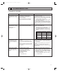
NOTES :
1. Since the indoor fan motor (MF) is connected with 230V power, using 208V power will require a setting change of the dip switch (SW7<I.B>) on the indoor controller board as shown in fig : w 1.
ON
ON
fig w1 Indoor fan motor (MF) for 208V.
SW7
OFF
OFF
1234
1234
2. Since the indoor transformer (T) is connected with 230V power if 208V power is used. Change the wiring connection showing fig : w 2.
fig w2 When power supply is
240V YELLOW
230V
3.
4.
5.
6.
YELLOW
208V RED
Since the outdoor side electric wiring may change be sure to check the outdoor unit electric wiring for servicing.
Indoor and outdoor connecting wires are made with polarities, make wiring matching terminal numbers.
Symbols used in wiring diagram above are, ¤¤ : Connector, / : Terminal block.
Emergency operation
If remote controller or microcomputer fails but there is no other trouble, emergency operation is possible by setting dip switch (SW3<I.B>) on the indoor controller board.
[Check items]
(1)Make sure that no other trouble exist the outdoor unit. Trouble with the outdoor unit prevents emergency operation.
(If any trouble exists the outdoor unit error code "P8" will be displayed on the remote controller and the trouble position will be shown on the outdoor controller
board LED. See electric wiring diagram of the outdoor unit for details.)
(2)Make sure that there is no trouble with the indoor fan.
Emergency operation will be continuous operation mode due to power ON/OFF (ON/OFF with the remote controller is not possible).
[Emergency operation procedure]
(1)Set the dip switch (SW3<I.B>) on the indoor controller board to 1 on and 2 off for cooling and 1 - 2 on for heating.
(2)Turn on outdoor unit side circuit breaker, then indoor unit side circuit breaker.
(3)During emergency operation indoor fan runs at high speed but automatic vane remains stopped.
If the air outlet is blocked up with the vane, Open it with your hands.
(4)Thermostat will not function. Cold air blows out for defrosting during heating thus do not operate defrosting for along time.
(5)Emergency cooling should be limited to 10 hours maximum.
(The indoor unit heat exchanger may freeze).
(6)After every operation, switch the fan connector to FAN1, and set all dip switches (SW3<I.B>) to OFF.
BG79N687H01
22
OC120--1.qxp
24/6/97 12:22 AM
Page 23
MODELS PUH18EK WIRING DIAGRAM
COMPRESSOR CAPACITOR
FAN CAPACITOR
FUSE<6A>
FAN CONTROLLER
CRANKCASE HEATER
LED<CHECK,SERVICE>
COMPRESSOR
FAN MOTOR<INNER THERMOSTAT>
OUTDOOR CONTROLLER BOARD
SW1•2•3<0.B>
T
TB1,3
X11<O.B>
X12<O.B>
X13<O.B>
SW3
2 1
4 3 2 1
X13
X12
63H1
X11
MF2
LD1
LD2
LD3
LD4
LD5
LD6
LD7
LD8
63H2
21R
21
S4
S
A
CH
ZNR
R/1
WHT
WHT
52C
GRY
GRY
BLK
BLK
RED
BLK
BLK
21S4
S/2
T/3
BLU
BLU
GRY
TRF
GRY
SV
63H2
63H1
HC
52C
B
WHT
WHT
MF1
51CM
F
208V
MF
230V
RED
BLU 4
WHT 3
RED
RED
2
C1
ORN 1 ORN
BLK
TB1
52C
L1
RED
L2
BLK
R
U
T
W
BLU
WHT 2
GR
R
51C 1 WHT C
BLU
Main function of LED(when both Nos.1 and 2 of
Output display (light)
RED
C
GRN
LED NO.
FC
CN4
CN3
ORN
T
X11
26C
RED
RED
12.3V AC
X12
X14
RED
RED
X13
5
OFF
ON
CN4T
4 3 2 1 4
BRN 12.3V AC
X14
CN2
WHT
WHT
3
2
1
60Hz
PROTECT HIGH PRESSURE SWITCH
O.B
SW2
1{ 208/230V
CONTROL HIGH PRESSURE SWITCH
RT
SW1
POWER SUPPLY
BYPASS VALVE RELAY
VARISTOR
BYPASS VALVE COIL
R.V COIL
OVERCURRENT RELAY
CONTACTOR
LED
YLW
ORN
BRN
TB3
RED
X14<O.B>
ZNR<O.B>
21R
21S4
51C
52C
63H1
63H2
BLU
WHT
CONNECTING WIRES
12V DC (polar)
OUTDOOR COIL THERMSTOR
<32˚F/15kΩ,77˚F/5.4kΩ>
SELECTOR<CHECK,SERVICE>
TRANSFORMER
TERMINAL BLOCK
CRANKCASE HEATER RELAY
COMPRESSOR RELAY
R.V RELAY
BLU
WHT
1
2
3
FROM INDOOR UNIT
RT
BRN
BRN
YLW
YLW
YLW
YLW
RED
RED
BLU
C
C1
F<O.B>
FC<O.B>
HC
LD1~LD8
MC
MF
O.B
SW3
MC
S
are "OFF")
Check display (flash)
LD1
Compressor indoor command
—
LD2
Heating indoor command
LD3
63H1
ON
RT short/open
LD4
Compressor
ON
63H2 funcitons
LD5
Outdoor fan
ON
LD6
R.V.coil
ON
LD7
Bypass valve
ON
RT overheat protection
LD8
Crankcase heater
ON
Defective input
—
—
—
How to use SW1 and 2
● Pressing SW1 erases the past check contents
loaded on the microcomputer.
● The output display (light) remains during operation but pressing SW2 displays the past check
contents in flashing mode. Pressing the switch
again retums to output display (light).
NOTES : 1. If the operation stops to function of the protection device, the check display flashes.
2. Symbols used in wiring diagram above are. / :Terminal block, ¤¤¤ :Connector, ¤ :PC board insertion tab.
CAUTION FOR SERVICING
s
● The connector marked —¤—
is to turn the compressor ON-OFF during servicing.
The compressor stops by disconnecting the white connector as shown at the right.
White connector
CAUTIONS FOR POWER SUPPLY WIRING
● Since LD8 lights when normal power is turned "ON", check the power supply with the "ON"
or "OFF" LD8.
w Since the indoor transformer (T) is connected with 230V power, if 208V power is used,
change the wiring connection as shown in the right figure.
w When Power Supply is 208V
RED
208V
WHITE
ORANGE 230V
CAUTION FOR INDOOR AND OUTDOOR CONNECTING WIRES
● Since the indoor and outdoor connecting wires has polarity, make sure to connect the same terminal numbers (1,2,3) for indoor
and outdoor units.
23
OC120--1.qxp
24/6/97 12:22 AM
Page 24
MODELS PUH24/30/36EK WIRING DIAGRAM
COMPRESSOR CAPACITOR
FAN CAPACITOR
COMPRESSOR START CAPACITOR
FUSE<6A>
FAN CONTROLLER
CRANKCASE HEATER
LED<CHECK,SERVICE>
COMPRESSOR<INNER THERMOSTAT>
FAN MOTOR<INNER THERMOSTAT>
CONNECTING WIRES
12V DC (poler)
OUTDOOR CONTROLLER BOARD
RESISTOR
OUTDOOR COIL THERMISTOR
RT
<32˚F/15kΩ, 77˚F/5.4kΩ>
SW1•2•3<O.B> SELECTOR<CHECK,SERVICE>
T
TRANSFORMER
TB1,3
TERMINAL BLOCK
X11<O.B>
CRANKCASE HEATER RELAY
X12<O.B>
COMPRESSOR RELAY
RT
O.B
4 3 2 1
SW2
SW3
2 1
60Hz
X13
X12
63H1
X11
MF2
MF1
51CM
F
21
S4
A
ZNR
R/1
S/2
T/3
BLU
BLU
WHT
BLU
GRY
S
CH
WHT
WHT
52C
GRY
GRY
BLK
BLK
RED
21R
21S4
GRY
TRF
BLK
BLK
SV
208V
63H2
63H1
MF1
HC
52C
BLU
BLU
4
WHT
WHT
3
RED 2 RED
C1
1
ORN
ORN
B
WHT
WHT
YLW 1
2
MF2 BRN
3
WHT 4
BLU
230V
RED
BLK
TB1
1[ 208/230V
FC
CN4
63H2
ORN
T
X11
CN3
RED
RED
12.3V AC
X12
26C
X14
RED
RED
X13
5
OFF
ON
CN4T
4 3 2 1 4
BRN 12.3V AC
X14
CN2
WHT
WHT
3
2
1
LD1
LD2
LD3
LD4
LD5
LD6
LD7
LD8
SW1
POWER SUPPLY
R.V RELAY
BYPASS VALVE RELAY
VARISTOR
COMPRESSOR START RELAY
BYPASS VALVE COIL
R.V COIL
CONTACTOR
CONTROL HIGH PRESSURE SWITCH
PROTECT HIGH PRESSURE SWITCH
LED
YLW
ORN
BRN
TB3
RED
X13<O.B>
X14<O.B>
ZNR<O.B>
19
21R
21S4
52C
63H1
63H2
BLU
WHT
1
2
3
FROM INDOOR UNIT
O.B
R
BRN
BRN
YLW
YLW
YLW
YLW
RED
RED
BLU
C
C1,2
C5
F<O.B>
FC<O.B>
HC
LD1~LD8
MC
MF1,2
YLW
C1
BRN
WHT
BLU
52C
L1
RED
L2
BLK
R
T
GR
U
W
GRN
BLU
R
WHT
WHT C
BLU
RED
C
MC
S
NOTES : Symbols used in wiring diagram above are. / :Terminal block, ¤¤¤ :Connector, ¤ :PC board insertion tab.
CAUTION FOR SERVICING
s
White connector
is to turn the compressor ON-OFF during servicing.
● The connector marked —¤—
The compressor stops by disconnecting the white connector as shown at the right.
CAUTION FOR POWER SUPPLY WIRING
● Since LD8 lights when normal power is turned "ON", check the power supply with the "ON"
or "OFF" LD8.
w Since the indoor transformer (T) is connected with 230V power, if 208V power is used,
change the wiring connection as shown in the right figure.
w When Power Supply is 208V
RED
208V
WHITE
ORANGE 230V
CAUTION FOR INDOOR AND OUTDOOR CONNECTING WIRES
● Since the indoor and outdoor connecting wires has polarity, make sure to connect the same terminal numbers (1,2,3) for indoor
and outdoor units.
24
OC120--1.qxp
24/6/97 12:22 AM
6
Page 25
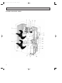
REFRIGERANT SYSTEM DIAGRAM
Protect
Control
high pressure high pressure
switch
switch
Oil separator
Service
Outdoor unit
port
4-way valve
(check)
PKH18FK
Refrigerant pipe
(option)
{5/8"
Ball valve
(with heat insulator)
Strainer
Indoor unit
Flexible tube
Strainer
Flared
connection
Service
port
(check)
Outdoor coil
thermistor
RT
Fusible
plug
Bypass
valve
Restrictor
valve
Accumulator
Indoor coil
thermistor
RT2
Restrictor
valve
Distributor
Capillary
tube
({0.126x{0.071x15.7)
Muffler Compressor
PKH24FK
Refrigerant pipe
(option)
{5/8"
Ball valve
(with heat insulator)
Strainer
Flexible tube
Strainer
Indoor coil
thermistor
RT2
Flared
connection
Restrictor
valve
Distributor
Outdoor unit
Outdoor coil
thermistor
RT
Service
port
(check)
Fusible
plug
Bypass
valve
Accumulator
({0.126x{0.071x9.8)
Muffler Compressor
Restrictor
valve
Capillary
tube
({0.126x{0.063
x17.3)x2
Strainer
Protect
high pressure
switch
Control
high pressure
switch
Oil separator
Outdoor unit
Service
port
4-way valve
(check)
PKH-30/36FK
Indoor unit
Refrigerant pipe
(option)
{3/4
(with heat insulator) Ball valve
Strainer
Flexible tube
Strainer
Indoor coil
thermistor
RT2
Protect
high pressure
switch
Ball valve
Refrigerant pipe
(with service port)
(option)
{3/8"
(with heat insulator)
Capillary
tube
Capillary
tube
({0.157x{0.079
x33.5)
Strainer
Ball valve
Refrigerant pipe
(with service port)
(option)
{3/8"
(with heat insulator)
Control
high pressure
switch
Oil separator
Service
port
4-way valve
(check)
Indoor unit
COOL
HEAT
Restrictor
valve
Distributor
Capillary
tube
PKH30FK({0.157x{0.079x11.4)
PKH36FK({0.157x{0.079x11.4)
Flared
connection
Outdoor coil
thermistor
RT
Service
port
(check)
Fusible
plug
Bypass
valve
Accumulator
Muffler
Compressor
Capillary tube
Ball valve
Refrigerant pipe
(with service port)
(option)
{1/2"
(with heat insulator)
Strainer
Restrictor
valve
Capillary tube
PUH30EK
({0.157x{0.079
x23.6)x2
PUH36EK
({0.157x{0.079
x17.7)x2
w Capillary tubesize:(ODxIDxLength)
The symbol { indicates diameter.
25
OC120--1.qxp
7
24/6/97 12:22 AM
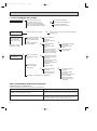
Page 26
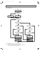
OPERATION FLOW-CHART
MAIN OPERATION
START
Power circuit
breaker
1
NO
YES
YES
Check SW
ON twice
NO
Operation SW
ON
w 1
YES
NO
“OFF” timer
YES
NO
NO
Set time
complete
“ON” timer
NO
YES
YES
YES
Set time
complete
w 2
NO
NO
Trouble
YES
STOP
Trouble STOP
PROTECTION DEVICE
SELF HOLD RELEASE
PROTECTION DEVICE
SELF HOLD
Remote controller
operation display
Operating mode
(COOL)
NO
Operating mode
(DRY)
w 3
Remote controller
trouble display
Remote controller
indicator lamp OFF
NO
Operating mode
(HEAT)
Indoor side
w 4
Fan STOP
NO
w 6
Operating mode
(FAN)
NO
Auxiliary heater OFF
YES
COOL operation
YES
DRY operation
YES
HEAT operation
YES
w 7
FAN operation
Auto COOL/HEAT
operation
Outdoor side
w 5
Compressor OFF
Fan STOP
Four-way valve OFF
w1 In addition, the centralized and remote control can be operated.
w2 The modes which indicate the sources of trouble are listed below.
● EO=Signal transmitting/receiving error
● P1=Room temperature thermistor malfunction
● P2=Indoor coil thermistor malfanction
● P4=Drain sensor malfunction
● P5=Drain over flow
● P6=Coil frost/overheat protection
● P7=System error
● P8=Outdoor unit trouble
w3 The CHECK swich will show if an error has occurred in the past.
w4 Fan runs on low speed for 1 minute in order to remove overheat air.
w5 The 3-minute (6 minutes … heating mode) time-delay functions after compressor stops.
w6 FAN or AUTO mode is selected by the indoor dipswitch setting.
w7 In FAN mode, fan speed and vane operation depend on the remote controller setting. (Compressor is OFF.)
26
OC120--1.qxp
24/6/97 12:22 AM
Page 27
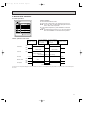
COOLING OPERATION
COOL operation
Four-way valve/OFF
NO
Initial
COOLING
w 8
YES
Vane intial
setting
Vane
60 deg downward angle
70 deg downward angle
NO
YES
NO
Fan speed
LOW
YES
NO
Vane setting notch
Downward discharge
1 hour
YES
Vane horizontal
airflow
w 9
NO
Compressor
thermostat
ON
YES
NO
Allowance
cancel
NO
YES
3-minute
time delay
YES
6-minute
time delay
NO
3-minute
compressor opration
NO
Aliowance
period
NO
6 minute
time delay
NO
YES
Allowance set
w 10
Coil frost protection
YES
YES
Coil frost
prevention
NO
w 11
NO
Cooling area
YES
NO
10-minute
compressor operation
NO
YES
1 min continue
YES
Allowance cancel
FAN speed
LOW
Coil frost
protection
YES
NO
NO
Indoor coil
tempreature is
50¡F or higher
16-minute
compressor operation
YES
Indoor pipe
temperature is
34¡F or lower
NO
Compressor ON
YES
YES
Coil frost
prevention
NO
FAN speed
LOW 5 min
elapse
NO
YES
Outdoor unit
trouble
3-minute
time delay
Coil frost
prevention release
Compressor OFF
1
w8 When operation stops or changes to cooling or dry mode, the auto vane turns to a horizontal angle. IF operation changes during auto vane SWING, the auto vane will continue to swing.
w9 When operating TEST RUN, the thermostat will be continuously ON.
w10After 3 minute compressor operation, if the indoor coil thermistor reads -59°F or below for 3 minutes, the compressor will stop for 6 minutes.
w11Cooling area : Indoor coil temperature is more than 9 degrees above the room temperature.
Heating area : Indoor coil temperature is more than 9 degrees below the room temperature.
FAN area : Indoor coil temperature is within 9 degrees either way of the room temperature.
27
OC120--1.qxp
24/6/97 12:22 AM
Page 28
HEATING OPERATION
A
Heat operation
NO
Intial
HEATING
Vane setting notch
w 11
Heating area
w 15
YES
NO
Vane intial setting
Defrost
30 min. elaspe
PKH-FK
Type
YES
Defrost release
NO
NO
3-minute
Auxiliary heater
OFF
NO
Indoor coil
thermstor is 60¡C
or higher
NO
FAN speed
Low notti
NO
2
YES
YES
Defrosting
Outdoor unit trouble
NO
Four-way valve ON
1
YES
Hor adjust
in process
YES
Airflow 10% up
NO
YES
Compressor ON
YES
NO
w 9
10-minute
compressor
operation
YES
NO
YES
Compressor
thermostat ON
3 min.restart
prevention
HOT adjust
6 min. elapse
B
Allowance cancel
2
NO
6 min. restart
prevention
Indoor piping
-5¡F or lower
w 11
YES
Heating
area
NO
FAN STOP
Outdoor unit
trouble
FAN SPEED very low
Auxiliary heater
ON
NO
w 11
YES
Ariflow area
20 min.elaspe
YES
w 11
Compressor OFF
NO
FAN SPEED
Low
NO
Auxiliary heater
thermostat ON
YES
YES
Indoor piping
140¡F or higher
Auxiliary heater ON
FAN SPEED
Low 2 min.
elapse
YES
NO
FAN SPEED
setting notch
Hot adjust
release
YES
Auxiliary heater OFF
Compressor ON
FAN SPEED
Very low airflow
YES
NO
A
Hot adjust start
YES
B
YES
Indoor piping
131¡F or lower
NO
Indoor piping
95¡F or higher
NO
Allowance cancel
YES
w 10
Airflow area
Heating area
Outdoor unit
trouble
Overheat remote
START
NO
NO
Airflow area
Cooling area
NO
Indoor unit
158¡F or higher
YES
YES
Defrost operation
START
Allowance
period
Four-way valve
OFF
YES
Overload protect
NO
6-minute restart
prevention
Allowance set
1
Compressor OFF
Auto COOL/HEAT
operation
NO
1
w 16
Initial mode
w 17
YES
NO
T1 >
=T0
YES
COOL mode
COOL mode
NO
HEAT mode
NO
NO
T1 < (T0 - 2)
YES
After 15min.
T1<(T0-2)
T1>(T0 + 2)
YES
After 15min.
T1>(T0 + 2)
YES
YES
NO
NO
COOL operation
HEAT operation
1
HEAT operation
Cool mode
set
1
w15 (!) Until Low airflow is set while hot adjustment
(@) While defrosting (FAN STOP)
(#) When thermostat is OFF
In the case of(!), (@) and (#) above, airflow is horizontal regardless the VANE setting.
w16 When AUTO operation is started, COOL or HEAT mode is selected automatically.
w17 T1 : Room temperature.
To : Set temperature
28
NO
FAN setting notch
OC120--1.qxp
24/6/97 12:22 AM
Page 29
DRY OPERATION
DRY
operation
Four-way valve / OFF
NO
Initial dry
operation
w8
YES
Vane
setting notch
Vane intial setting
YES
w 12
Room tempereature is
64°F or lower
NO
NO
During
compressor ON
YES
3-minute
compressor
operation
NO
NO
YES
NO
YES
3-minute
time delay
w9
Compressor &
thermostat ON
YES
Compressor &
thermostat
ON
w9
NO
YES
NO
Compressor ON
time completes
10-minute
compressor
OFF
NO
YES
YES
10-minute compressor
OFF timer start
Compressor OFF
w 14
Fan STOP
w 13
Compressor ON
time set
Compressor ON
w 14
Fan speed LOW
1
w8 ~ 9
w12
w13
w14
Refer to page 35.
When room temperature is 4°F or below, the compressor cannot operate.
When room temperature rises over 64°F, the compressor starts after a 3-minute time delay.
Compressor ON time is decided by room temperature. Refer to page 35.
In dry operation, compressor ON makes the fan speed LOW and compressor OFF stops the fan.
It is not possible to set the fan speed with the remote controller
29
OC120--1.qxp
8
24/6/97 12:22 AM
Page 30
MICROPROCESSOR CONTROL
1.OUTLINE OF MICROPROCESSOR CONTROL
INPUT to remote controller
● OFF-ON switching.
● COOL/DRY-AUTO-HEAT selector switching.
● Thermostat setting.
● TIMER mode selector-switching and Timer
setting.
● HIGH-LOW fan speed switching.
● AUTO Vane selector (AIR DISCHARGE)
switching.
● TEST RUN switching.
● CHECK mode switching.
(Self diagnostic trouble shooting)
● Processes and transmits
orders.orders.
OUTPUT to remote controller
Remote controller
● LCD indicator
-CENTRALLY CONTROLLEDSTAND BY
DEFROST ON
F
TIMER OFF
AUTO STOP
AUTO START
ON/OFF
POWER
CHECK DRY
COOL
HEAT
HEAT
CHECK
SET TEMP
AUTO
COOL/DRY
SET
WARMER
TEMPERATURE
HR
LOW HIGH
F
AUTO RETURN
CHECK TEST RUN
TIMER
MODE
COOLER
HOURS
FAN SPEED LOW/HIOGH
AIR
UP/DOWN SWING STOP
DISCHARGE
CHECK
TEST RUN
MITSUBISHI ELECTRIC
Non-polar, two-wire cable
maxinmum length 500 meters
12VDC
Indoor
unit
Remote controller board
Signal
Indoor controller board
INPUT from indoor unit
● Room temperature thermistor (RT1)
● Indoor coil thermistor (RT2)
OUTPUT to indoor unit
● Receives orders from remote controller and temperature data from indoor unit.
● Processes orders and data.
● Controls indoor and outdoor operation.
● Self diagnostic function.
w System control operation.
w Emergency operation.
w Set by dipswitch on indoor controller board.
● Transmits the power to remote controller.
Polar three-wire cable
● Compressor protectiondevice working
● Defrosting
START-STOP
● Fan speed control.
● Crankcase heater control
ON-OFF.
● Self diagnostic function
30
Outdoor unit
12VDC
Independent Control of
Outdoor Unit
1
2
3
OUTPUT to outdoor unit
1 2 3
● Autovane’s angle setting.
● Booster heater ON-OFF Control.
● Emergency stop.
● Compressor and
outdoor fan : ONOFF
● Operation mode
change :COOLHEAT.
OC120--1.qxp
24/6/97 12:22 AM
Page 31
2. INDOOR UNIT CONTROL
2-1 COOL operation
-CENTRALLY CONTROLLEDSTAND BY
DEFROST ON
POWER
CHECK DRY
COOL
HEAT
HEAT
CHECK
SET TEMP
TIMER OFF
AUTO STOP
AUTO START
F
TIMER
F
AUTO RETURN
ON/OFF
COOL/DRY
SET
WARMER
TEMPERATURE
HR
LOW HIGH
AUTO
<How to operate>
1 Press POWER ON/OFF button.
2 Press COOL / DRY button to set operation mode to Cool.
NOTE : "Cool" and "DRY" are alternately displayed each time
COOL / DRY button is pressed.
3 To set desired temperature, press WARMER or COOLER
button.
NOTE : Set temperature changes by 2˚F in the range 66~86˚F,
each time WARMER or COOLER button is pressed.
COOLER
MODE
HOURS
FAN SPEED LOW/HIOGH
AIR
UP/DOWN SWING STOP
DISCHARGE
CHECK
CHECK TEST RUN
TEST RUN
MITSUBISHI ELECTRIC
<COOL operation time chart>
Operation starts by
POWER button
ON.
The room temperature
displayed on Remote
controller becomes equal
to set temperature.
The room temperature
displayed on Remote
controller rises above
set temperature.
Operation stops by
POWER button
OFF.
ON
Thermostat
OFF
Indoor fan
LOW or HIGH
LOW or HIGH
ON
OFF
Initally 10 degrees
(Changeable by remote controller setting)
CLOSE
Auto vane
CLOSE
ON
Booster heater
OFF
ON
Compressor
OFF
OFF
Minimum 3 minutes W1
w1 Even if the room temperature displayed on remote controller rises above the set temperature during this period, the compressor will not start until this period
has ended.
31
OC120--1.qxp
24/6/97 12:22 AM
Page 32
(1) Compressor control
1 3-minute time delay
To prevent overload, the compressor will not start within 3 minutes after stop.
2 The compressor runs when the room temperature displayed on remote controller is higher than set temperature.
The compressor stops when the room temperature displayed on remote controller is equal to or lower than the set temperature.
3 The compressor stops in check mode or during protective functions.
4 Coil frost preventionTo prevent indoor coil frost, the compressor will stop when the indoor coil thermistor (RT2) reads 34°F
or below after the compressor has been continuously operated for at least 16 minutes or more. When the indoor coil temperature rises to 50°F or above, the compressor will start after a 3-minute time delay.
NOTE : The start temperature of coil frost prevention changes 34°F to - 27°F.
5 Coil frost protection
When indoor coil temperature becomes 5°F or below, coil frost protection will proceed as follows.
<Start condition>
After the compressor has been continuously operated for 3 minutes or more,and the indoor coil temperature has been
5°F or below for 3 minutes,the coil frost protection will start.
<Coil frost protection>
Compressor stops for 6 minutes, and then restarts.
If the start condition is satisfied again during the first 10 minutes of compressor operation, both the indoor and outdoor
units stop, displaying a check code of “P8” on the remote controller.
<Termination conditions>
Coil frost protection is released when the start condition is not satisfied again during the allowance, or when the COOL
mode stops or changes to another mode.
(2) Indoor fan control
Indoor fan speed LOW/HIGH depends on the remote controller setting.
However, if an outdoor unit abnormality is detected, the indoor fan speed will be LOW, regardless of the remote controller
setting.
When the outdoor unit abnormality detection is released and the fan speed returns to the set speed, the quiet cycle control
will work.
(a) Normal control
( i ) Fan speed LOW/HIGH depends on the remote controller setting regardless of the thermostat ON/OFF.
(ii) Fan speed will remain on LOW if an abnormality in outdoor unit is detected. (5 minutes)
When the abnormality detection is released, the fan speed returns to the set speed.
5 minutes
SET
5 minutes
SET
LOW
LOW
OFF
NOTE 1 : Fan stops immediately if the unit stops or the check mode is started.
32
1 Start-up of outdoor unit abnormality detection.
2 Release of outdoor unit abnormality detection.
3 Unit stop due to outdoor unit abnormality
with P8 indication.
OC120--2.qxp
24/6/97 12:31 AM
Page 33
(3) Auto vane control
Auto vane position is set to 10degrees discharge at the start-up of COOL operation. It can then be changed by the remote
controller.
(a) Stop mode (fixed operation)
(!) At start-up of COOL operation, the auto vane is set to 10 degrees discharge direction.
(@) Discharge direction can be changed with AIR DISCHARGE UP/DOWN botton.
1 Fan speed : LOW
10°
discharge
60°
discharge
70°
discharge
60°
discharge
70°
discharge
2 Fan speed : HIGH
10°
discharge
30°
discharge
(b) SWING mode
(!) The vane motor turns ON when the SWING mode is selected.
The vane motor is continuously ON during SWING mode.
(@) When SWING mode is changed to STOP mode, the discharge direction returns to the position of the last STOP mode.
<AUTO RETURN>
1 Fan speed : LOW
10°
discharge
60°
discharge
70°
discharge
AUTO
RETURN
AUTO
RETURN
60°
discharge
70°
discharge
2 Fan speed : HIGH
10°
discharge
30°
discharge
When 60 degrees or 70 degrees discharge is selected with the LOW fan speed in COOL operation, “Auto RETURN” will
appear below the temperature display. One hour later, the discharge direction returns to 10 degrees automatically and
“AUTO RETURN” will disappear. If the discharge direction is set to 10 degrees during “AUTO RETURN” indication, the
time counting for AUTO RETURN is cancelled.
33
OC120--2.qxp
24/6/97 12:31 AM
Page 34
<Auto vane drive>
(a) The vane is driven by DC12V motor.
(b) Air discharge direction is selected depends on the number of pulse were sended.
(c) Before start driving the auto vane, detect the standard position first, output the number of pulse to each air discharge.
(d) The speed of the auto vane drive for both open and close are setted at 200 pulse/sec.
(e) Method of driving the auto vane.
1 Detecting the standard position:
Output 1600 pulse to the opening direction.
2 Position setting:Output the number of pulse indicated no below chart to the closing direction.
The number of pulse outputed after
detecting the standard position
Close
1600
Horizontal
680
Downward A
578
Downward B
283
Downward C
113
(4) Detecting abnormalities in the outdoor unit
After the compressor has been continuously operated for 3 minutes, if the difference between the indoor coil temperature
and room temperature is out of RANGE C for 1 minute, the indoor fan speed will turn to LOW. Five minutes later, if the difference is still out of
RANGE C,the outdoor unit is functioning abnormally. Thus, the compressor stops and check code “P8” appears on remote
controler.
RANGE A : Indoor coil temperature is more than 9 degrees above room temperature.
RANGE B : Indoor coil temperature is within 5 degrees either way of room temperature.
RANGE C : Indoor coil temperature is more than 9 degrees below room tempetature.
Indoor coil temperature
minus room temperature
(degree)
+9
0
-9
34
RANGE A
RANGE B
RANGE C
OC120--2.qxp
24/6/97 12:31 AM
Page 35
2-2 DRY operation
-CENTRALLY CONTROLLEDSTAND BY
DEFROST ON
CHECK DRY
COOL
HEAT
CHECK
SET TEMP
TIMER OFF
AUTO STOP
AUTO START
F
HR
LOW HIGH
F
AUTO RETURN
CHECK TEST RUN
ON/OFF
POWER
HEAT
AUTO
COOL/DRY
SET
WARMER
TEMPERATURE
TIMER
<How to operate>
1 Press POWER ON/OFF button.
2 Press COOL / DRY button to set operation mode to DRY.
NOTE : "Cool" and "DRY" are alternately displayed each time
COOL / DRY button is pressed.
3 To set desired temperature, press WARMER or COOLER
button.
NOTE : Set temperature changes by 2˚F in the range 66~86˚F,
each time WARMER or COOLER button is pressed.
MODE
COOLER
HOURS
FAN SPEED LOW/HIOGH
AIR
UP/DOWN SWING STOP
DISCHARGE
CHECK
TEST RUN
MITSUBISHI ELECTRIC
<DRY operation time chart>
The room temperature
dislayed on remote controller becomes equal to
set temperature.
Operation starts by
POWER button
ON.
The room temperature
dislayed on remote controller rises above set
temperature.
Operation stops by
POWER button
OFF.
ON
Thermostat
OFF
LOW speed
LOW speed
ON
Indoor fan
OFF
30
Initally 10 degrees discharge
(Changeable by remote controller setting)
CLOSE
Auto vane
30
CLOSE
ON
Booster heater OFF
ON
Compressor
OFF
OFF
Minimum 3 minutes w 1
w1 Even if the room temperature dispayed on remote controller above the set temperature during this period, the compressor will not start until this period
has ended.
(1) Compressor control
13-minute time delay
To prevent overload, the compressor will not start within 3 minutes after stop.
2The compressor runs when the room temperature displayed on remote controller
is higher than the set temperature.
The compressor stops when the room temperature displayed on remote controller
is equal to or lower than the set temperature.
3The compressor stops in check mode or during protective functions.
4The compressor will not start when the room temperature displayed on remote controller
is below 64°F.
The compressor starts intermittent operation when the power is turned ON with room temperature above 64°F. The compressor ON/OFF time depends on the thermostat ON/OFF and the following room temperatures.After 3-minute compressor operation,
● If the room temperature thermistor reads above 82°F with thermostat ON, the compressor will operate for 6 more minutes and then stop for 3 minutes.
● If the room temperature thermistor reads 79°F—82°F with thermostat ON, the compressor will operate for 4 more minutes and then stop for 3 minutes.
● If the room temperature thermistor reads 75°F—79°F with thermostat ON, the compressor will operate for 2 more minutes and then stop for 3 minutes.
● If the room temperature thermistor reads below 75°F with thermostat ON, the compressor will stop for 3 minutes.
● If the thermostat is OFF regardless of room temperature, the compressor will stop for 10 minutes.
5Coil frost protection in DRY operation is the same as in COOL operation.
6Coil frost prevention does not operate in DRY operation.
(2) Indoor fan control
The indoor fan runs on LOW speed during compressor operation. The fan speed cannot be changed with the remote controller. Also, the indoor fan does not run during compressor OFF.
(3) Auto vane & drain pump controls
Same as in COOL operation
(4) Detecting abnormalities in the outdoor unit
An abnormality in the outdoor unit can not be detected in DRY operation.
35
OC120--2.qxp
24/6/97 12:31 AM
Page 36
2-3 HEAT operation
-CENTRALLY CONTROLLEDSTAND BY
DEFROST ON
CHECK DRY
COOL
HEAT
CHECK
SET TEMP
TIMER OFF
AUTO STOP
AUTO START
F
HR
POWER
HEAT
AUTO
SET
WARMER
TEMPERATURE
TIMER
MODE
<How to operate>
1 Press POWER ON/OFF button.
2 Press HEAT button to set operation mode to HEAT.
3 To set desired temperature, press WARMER or COOLER
button.
<Display in HEAT operate>
"STAND BY" is displayed from HEAT operation start until warm
air begins to blow.
"DEFROST" is displayed during defrosting.
ON/OFF
COOL/DRY
COOLER
HOURS
FAN SPEED LOW/HIOGH
LOW HIGH
AIR
UP/DOWN SWING STOP
DISCHARGE
F
AUTO RETURN
CHECK TEST RUN
CHECK
TEST RUN
MITSUBISHI ELECTRIC
<HEAT operation time chart>
Operation starts by
POWER button
ON.
The room temperature
displayed on remote controller falls below set
tem-
The room temperature
displayed on remote controller becomes equal to
set temperature.
Operation stops by
POWER button
OFF.
ON
Thermostat
OFF
Extra LOW w 1
ON
Indoor fan
Extra LOW w 1
LOW or HIGH
LOW or HIGH
OFF
10¡
Close
Depends on remote
controller setting
Depends on remote
controller setting
10¡
Close
ON
Booster heater
w 1 Changeable by indoor
dipswitch J1 - 7 and
J1 - 8.
OFF
ON
Auto vane
LOW
OFF
Hot adjustment
Hot adjustment
OFF during thermostat OFF
hot adjustment
defrosting
ON
Compressor
OFF
Minimum 3 minutes w 2
ON
Power ON lamp
OFF
ON
STAND BY lamp
From POWER ON until
warm begins to blow
OFF
w2 Even if the room temperature displayed on remote controller rise above the set temperature during this period, the compressor will not start until this period has
ended.
36
OC120--2.qxp
24/6/97 12:31 AM
Page 37
(1) Compressor control
13-minute time delay
To prevent overload, the compressor will not start within 6, minutes after stop.
2The compressor runs when the the room temperature displayed on remote controller is lower than the set temperature.
The compressor stops when the the room temperature displayed on remote controller is equal to or higher than the set
temperature.
3The compressor stops in check mode or during protective functions.
4Overheat protection
<Start condition>
When the indoor coil thermistor reads 158°F or above, the overheat protection will start.
<Overheat protection>
The compressor stops for 6 minutes, and then restarts.
If the start condition is satisfied again within 10 minutes of compressor operation, both the indoor and outdoor units stop,
displaying a check code of “P6” on the remote controller.
<Termination conditions>
Overheat protection is terminated when the start condition is not satisfied again during the allowance (10-minute compressor operation), when operation mode changes to other mode, or when thermostat turns OFF.
(2) Indoor fan control
(a) Nomal control
(!)The indoor fan runs on EXTRA-LOW speed during the thermostat OFF.
EXTRA-LOW speed can be changed to LOW or HIGH speed by setting the (J1-7, J1-8) If the indoor coil temperature becomes more than 9 degrees below the room temperature during the thermostat OFF, the indoor fan will stop.
After, when the indoor coil temperature becomes within 9 degrees of room temperature, the indoor fan will run on
EXTRA-LOW speed.
(@)Hot adjustment Hot adjustment is a warm-up for HEAT operation
<Start conditions>
The hot adjustment works under any of the follwing conditions.
● HEAT operation starts.
● Defrosting ends.
● Thermostat turns ON.[Hot adjustment]
Initially, the indoor fan runs on EXTRA-LOW speed. When 5 minutes have passed or the indoor coil temperature
exceeds 95°F, the fan speed changes to LOW. Two minutes later, the hot adjustment ends. Then, the fan speed
depends on the remote controller setting.
(#)The indoor fan stops when the indoor coil temperature is within 9 degrees either way of room temperature.
($)To eliminate the remaining heat, the indoor fan runs for the first 1 minute after the booster heater is turned OFF.
37
OC120--2.qxp
24/6/97 12:31 AM
Page 38
(3) Auto vane control
(a) STOP mode (fixed operation)
(!) The discharge direction at the start-up of HEAT operation is the same as that of the previous operation.
(@) The discharge direction can be charged by the remote controller setting.
10°
discharge
30°
discharge
60°
discharge
70°
discharge
(only for New models)
(SWING)
(SW5-3:OFF/ON)
In the following cases, discharge direction becomes 10° regardless of the remote controller setting.
1 During the hot adjustment with fan speed at EXTRA-LOW
2 During defrosting with indoor fan OFF
3 During the thermostat OFF
(b) SWING mode
(!) The vane motor turns ON when the SWING mode is selected.
The vane motor is continuously ON during SWING mode.
(@) In the following cases, the discharge direction is 10° regardless of the remote controller setting.
1 During the hot adjustment with fan speed at EXTRA-LOW
2 During defrosting with indoor fan OFF
3 During thermostat OFF
(4) Booster heater control
When the room temperature is 5 degrees below the set temperature, the booster heater will turn ON.
When the room temperature is equal to the set temperature, booster heater will turn OFF.
During the hot adjustment, the booster heater will not work.
<Overheat prevention>
When the indoor coil thermistor rises to 140°F or above, the booster heater cannot work.
When the indoor coil thermistor falls to 131°F or below, the booster heater can work.
(5) Detecting abnormalities in the outdoor unit
When the outdoor unit is determined to be abnormal by the following causes, the compressor will stop and the check code
“ P8 ” will appear on the remote controller display.
w1 (See the next page.)
1 During compressor ON after hot adjustment
1 If the difference between the indoor coil temperature and room temperature is in the RANGE B, the indoor fan will
stop.
2 Within 20 minutes after entering RANGE B (except for the first 10 seconds),
a) If the temperature difference enters RANGE A, the hot adjustment stasrts,
b) If the temperature difference is still in RANGE B, the outdoor unit is deemed abnormal.
c) If the temperature difference enters RANGE C, defrosting starts.
Within 30 minutes after entering RANGE C,
●If the temperature difference does not return to RANGE B,the outdoor unit is deemed abnormal.
●If the temperature difference returns to RANGE B, the next 20 minutes is an allowance period. If the difference enter
RANGE A during the allowance, defrosting ends and the hot adjustment starts. If the difference does not enter
RANGE A during the allowance, the outdoor unit is deemed abnormal.
2 During compressor ON in hot adjustment
After 30 minutes of defrosting in hot adjustment, if the temperature difference is still in RANGE C, the outdoor unit is
determined to be abnormal.
3 During compressor OFF
After 20 minutes of thermostat OFF, if the indoor coil thermistor reads -13°F or below, the outdoor unit is determined to
be abnormal.
38
OC120--2.qxp
24/6/97 12:31 AM
Page 39
(6) Indoor coil thermistor abnormality detection
An abnormality can be detected during compressor ON, except for the following.
●For the first 30 minutes after the temperature difference between the indoor coil temperature and room temperature
enters the RANGE C.
●When the temperature difference enters the RANGE C until it moves to the RANGE B.
(7) Defrosting operation
After the outdoor unit starts the defrosting operation, when the temperature difference between the indoor coil temperature
and room temperature gets out of RANGE A and into RANGE B, the indoor unit starts the defrosting mode. After the outdoor unit stops the defrosting operation, when the temperature difference returns to the RANGE A, the indoor unit stops
the defrosting mode. While the indoor unit is in the defrosting mode, the indoor fan and the booster heater stop.
w1 RANGE A : Indoor coil temperature is more than 9 degrees above room temperataure.
RANGE B : Indoor coil temperature is within 9 degrees either way of room temperature.
RANGE C : Indoor coil temperature is more than 9 below room temperature
Indoor coil temperature
minus room temperature
(degree)
+9
0
-9
RANGE A
RANGE B
RANGE C
39
OC120--2.qxp
24/6/97 12:32 AM
Page 40
2-4 AUTO operation (Automatic COOL/HEAT change over operation)
-CENTRALLY CONTROLLEDSTAND BY
DEFROST ON
TIMER OFF
AUTO STOP
AUTO START
ON/OFF
POWER
CHECK DRY
COOL
HEAT
HEAT
CHECK
SET TEMP
AUTO
COOL/DRY
SET
WARMER
TEMPERATURE
F
TIMER
HR
<How to operate>
1 Press POWER ON/OFF button.
2 Press AUTO button to set operation mode to AUTO.
3 To set desired temperature, press WARMER or COOLER
button.
NOTE : Set temperature changes by 2˚F in the range 66~86˚F,
each time WARMER or COOLER button is pressed.
Once the desired temperature is set, operation mode is
switched automatically between COOL and HEAT
according to room temperature.
MODE
COOLER
HOURS
FAN SPEED LOW/HIOGH
LOW HIGH
AIR
UP/DOWN SWING STOP
DISCHARGE
F
AUTO RETURN
CHECK
CHECK TEST RUN
TEST RUN
MITSUBISHI ELECTRIC
(1) Initial mode
1 When AUTO operation starts after unit OFF.
● If the room temperature displayed on remote controller is higher than the set temperature, operation starts in COOL
mode.
● If the room temperature displayed on remote controller is equal to or lower than the set temperature, operation starts
HEAT mode.
2 When AUTO operation starts after COOL or HEAT operation, the previous mode continues.
(2)Mode change
1 HEAT mode changes to cool mode when 15 minutes have passed since the room temperature became 2 degrees
above the set temperature.
2 COOL mode changes to HEAT mode when 15 minutes have passed since the room temperature became 2 degrees
below the set temperature.
To:Set temperature (19
(degree)
28
)
When the room temperature displayed remote controller becomes2 degrees above the set temperature,
the operation mode can not be changed for 15 minutes.
Mode change (HEAT
COOL)
To + 4
To + 2
To
To - 2
To - 4
15 minutes
Start
15 minutes
Mininum 3 minutes
COOL mode
HEAT mode
Compressor
Mode change
(COOL HEAT)
HEAT mode
ON
OFF
Mininum 3 minutes
(3)Temperature range
AUTO operation is available under the outside air temperatures as follows.
-15.8
32
50
68
10¡F
-17¡F
Cooling range
Heating range
40
86
104
115¡F (Outside air temperature)
OC120--2.qxp
24/6/97 12:32 AM
Page 41
2-5 Auto vane control
<How to operate>
To change the air flow direction, press AIR DISCHARGE UP/DOWN button.
-CENTRALLY CONTROLLEDSTAND BY
DEFROST ON
CHECK DRY
COOL
HEAT
CHECK
SET TEMP
TIMER OFF
AUTO STOP
AUTO START
F
HR
LOW HIGH
F
AUTO RETURN
POWER
HEAT
AUTO
SET
WARMER
TEMPERATURE
TIMER
ON/OFF
COOL/DRY
COOLER
MODE
HOURS
FAN SPEED LOW/HIOGH
AIR
UP/DOWN SWING STOP
DISCHARGE
CHECK
CHECK TEST RUN
1
2
3
4
10°
30°
60°
70°
TEST RUN
MITSUBISHI ELECTRIC
<Remote controller display>
1 discharge
2 downward discharge
3 downward discharge
Available in COOL operation with fan speed on HIGH or
in HEAT operation.
Unavailable in DRY operation.
If fan speed changes from LOW to HIGH during 30°
downward discharge in COOL mode, the direction automatically changes to 10°.
4 downward discharge
Changes by pressing
the AIR DISCHARGE
UP/DOWN button.
(1) COOL/DRY operation
At the start-up of COOL or DRY operation, the discharge direction in automatically set to 10°. After, it can be changed to
another direction with AIR DISCHARGE UP/DOWN button on the remote controller.
<Auto return>
When 60° or 70° discharge is set with fan speed on LOW, “AUTO RETURN” appears below the room temperature display.
One hour later the direction changes to 10° degrees, automatically and “AUTO RETURN” disappears.
(2) HEAT operation
At the start-up of HEAT operation, discharge direction depends on the setting of the last operation.
After, it can be changed to another direction with AIR DISCHARGE UP/DOWN button. The discharge direction shifts to 10°
regardless of the remote controller settings under any of the following conditions.
● Thermostat OFF
● Defrosting
● Indoor fan speed EXTRA-LOW in hot adjustment
41
OC120--2.qxp
24/6/97 12:32 AM
Page 42
2-6 TIMER operation
<Timer function>
AUTO STOP ·········The air conditioner stops after the set time lapses.
-CENTRALLY CONTROLLEDSTAND BY
DEFROST ON
CHECK DRY
COOL
TIMER
HR
AUTO START ········The air conditioner starts after the set time lapses.
COOL/DRY
SET
WARMER
TEMPERATURE
F
TIMER OFF
AUTO STOP
AUTO START
AUTO
HEAT
HEAT
CHECK
SET TEMP
ON/OFF
POWER
AUTO OFF ············Timer is not active.
COOLER
MODE
HOURS
<How to operate>
FAN SPEED LOW/HIOGH
LOW HIGH
1. Press POWER ON/OFF button.
AIR
UP/DOWN SWING STOP
DISCHARGE
F
AUTO RETURN
CHECK
CHECK TEST RUN
2. Press TIMER HOURS button to select AUTO STOP or AUTO
TEST RUN
START.
MITSUBISHI ELECTRIC
3. Press TIMER HOURS button to set desired time.
Time setting is in 1 hour units for up to 24 hours.
Each time HOURS button is pressed, set time increases by 1 hour.
When HOURS button is pressed and held, the set time increases
by 1 hour every 0.5 seconds.
4. To cancel the timer operation, press POWER ON / OFF button.
<Timer setting example>
AUTO STOP
8
HR
This setting will stop the air conditioner in 8 hours.
With the lapes of time, time display changes in 1 hour units, showing remaining time.
2-7 Test run
<Before test run>
● After installing, wiring, and piping the indoor and outdoor units, check for refrigerant leakage, looseness in power supply or
control wiring, and mistaken polarity.
● Use a 500-volt megger to check the resistance between the power supply teminal block and ground to make sure that it is
at least 1.0MΩ.
Attention:
Do not use the air conditioner if resistance is less than 1.0MΩ.
-CENTRALLY CONTROLLEDSTAND BY
DEFROST ON
CHECK DRY
COOL
CHECK
SET TEMP
TIMER OFF
AUTO STOP
AUTO START
F
AUTO RETURN
CHECK TEST RUN
AUTO
SET
WARMER
TEMPERATURE
F
HR
LOW HIGH
POWER
HEAT
HEAT
TIMER
MODE
ON/OFF
COOL/DRY
COOLER
HOURS
FAN SPEED LOW/HIOGH
AIR
UP/DOWN SWING STOP
DISCHARGE
CHECK
TEST RUN
MITSUBISHI ELECTRIC
TEST RUN button
Displayed during test run
Indoor coil temperaure code Display
42
<How to operate>
1. Turn ON main breaker.
2. Press TEST RUN button twice. “TEST RUN” is displayed on
remote controller.
3. Press COOL / DRY button to check that cool air is being
discharged.
4. Press AIR DISCHARGE UP / DOWN button to check auto
vane operation.
5. Check outdoor fan operation.
6. Check compressor operation referring to the indoor coil
temperature code displayed on the remote controller. (See
next page.)
7. The test run works for 2 hours and stops automatically. To
cancel the test run, press POWER ON / OFF button or
TIMER MODE button.
8. After checking, turn OFF the main breaker.
OC120--2.qxp
24/6/97 12:32 AM
Page 43
(1) Indoor coil temperature code
During the test run, the indoor coil temperature code from 1 to 15 is displayed on the remote controller instead of room
temperature. The code should fall with the lapse of time in normal COOL operation, and should rise in normal HEAT
operation.
Code
Indoor coil
temperature
1
2
3
4
5
6
7
8
~40~34¡F
~50¡F
~59¡F
~68¡F
~77¡F
~86¡F
~95¡F
104¡F
9
10
11
12
13
14
Code
Indoor coil
temperature
~113¡F
~122¡F
~131¡F
~140¡F
~158¡F
15
Thermistor
abnormality
(2) Trouble during test run
● If the unit malfunctions during the test run, refer to section 10 in this manual entitled “TROUBLESHOOTING.”
● When the optional program timer is connected to the conditioner, refer to its operating instructions.
2-8 Emergency operation
When the remote controller or microprocessor malfunctions but all other parts are normal, emergency operation is started
by setting the dipswitch SW3 on the indoor controller board.
<Before emergency operation>
1. Make sure the compressor and the indoor fan are operating normally.
2. Locate the defect with the self-diagnostic function. When the self-diagnostic function indicates “protective function is
working”, release the protective function before starting the emergency operation.
CAUTION: When the self-diagnostic function indicates a check code of “P5” (drain pump malfunction), DO NOT start
the emergency operation because the drain may overflow.
<How to operate>
1. For emergency cooling, set the dipswitch SW3-1 to ON and SW3-2 to OFF.
For emergency heating, set the dipswitch SW3-1,2 to ON.
Emergency
cooling
1
1 ON
2
Emergency
heating
1
2
1.2 ON
Nomal
operation
1
2
1-2 OFF
Microcessor board
2. Turn ON the outdoor unit breaker and then turn ON the indoor unit breaker.
Emergency operation will now start.
3. During emergency operation, the indoor fan operates on high speed, but the swing louvers and the auto vanes do not
operate.
4. To stop emergency operation, turn OFF the indoor unit breaker.
NOTE: The remote controller POWER ON/OFF button can not start/stop emergency operations.
CAUTION: Do not use emergency cooling for more than 10 hours, as the indoor coil may freeze.
43
OC120--2.qxp
24/6/97 4:07 AM
Page 44
2-9 Interlock with ventilation system (LOSSNAY)
Mr. SLIM/LOSSNAY interlock operation is available by using the optional parts listed below.
(1) System organization
Relay box (PZ-12RB-E)
Relay box
Mr. SLIM
LOSSNAY
LOSSNAY
Power supply
Mr. SLIM
Power
supply
Remote
controller
LOSSNAY control switch (PZ-05SLB2-E)
Remote display
adapter
(PAC-SA88HA-E)
Remote
controller
LOSSNAY control switch
(PZ-05SLB2-E)
(2) Required parts are:
● Relay box (PZ-12RB-E) ••• Contact capacity 10A
● Remote display adapter (PAC-SA88HA-E)…An optional part for Mr. SLIM
● LOSSNAY control switch (PZ-05SLB-2-E)…For LOSSNAY individual operation
(3) Operation
1LOSSNAY turns ON/OFF according to Mr. SLIM ON/OFF
2While Mr. SLIM is OFF, LOSSNAY individual operation is available by using the LOSSNAY control switch.
When Mr. SLIM turns OFF with the LOSSNAY control switch at ON, LOSSNAY will continue to operate.
(4) Wiring.
1When the LOSSNAY control switch is used:
2When the LOSSNAY control switch is not used:
Mr. SLIM
Indoor controller
board
Remote
controller
Power supply
for Mr. SLIM
220 240V AC
Relay box
(PZ-12RB-E)
Connector
CN51
GRN
YLW
ORN
RED
BRN
Terminal block
A
Insulation
is needed
10m
LOSSNAY
Terminal block
B
L
N
HIGH
N
Relay box
(PZ-12RB-E)
A
B
Connecting wire
0.13mm 2 or over
Connecting wire
solid wire,
1.6 or 2.0
(field supplied)
RED
N
WHT
RED
WHT
N
HIGH
7
6
2
5
1
Circuit breaker
(field supplied)
L
Power
supply
N
50Hz
220 240V
RED
8
ORN
L
HIGH
ORN
LOW
YLW
4
WHT
Mr.SLIM
CN51
12V DC
Circuit
breaker
N
RED
DAMPER
3
L
N
Power supply
220 240V AC
ORN
DAMPER
WHT
LOSSNAY
Terminal
block
N
L
ORN
LOW
LOW
PL
HIGH
N HIGH
N
DAMPER
DAMPER
DAMPER
LOSSNAY control switch
(PZ-05SLB 2-E)
44
Junction box
(field supplied)
RED
WHT
RED
ORN
WHT
NOTE: For further information, refer to the
LOSSNAY technical & service manual.
OC120--2.qxp
24/6/97 12:32 AM
Page 45
2-10 Dip switch and jumper connector functions
Each figure shows the initial factory setting.
1 On remote controller board
(1) SW17(Address selector)
1 2 3 4 5 6 7 8 90
ON
OFF
SW17-1 ~ 6) For address setting
SW17-7) When two remote controllers are used, this switch sets the controller function.
OFF: The remote controller is set as a main controller.
ON: The remote controller is set as a sub controller.
SW17-8) Switch for system back-up
OFF: Without back-up
ON: With back-up
SW17-9) Switch for temperature unit
OFF: °C ( Celsius)
ON: °F (Fahrenheit)
SW17-0) Switch for louvers
OFF: Unit with louvers
ON: Unit without louvers
3. On indoor controller boaed
(1) J1 (Mode selector)
1
J1-1)
J1-4)
J1-5)
J1-6)
4
5
6
7
8
9
10
Switch that changes between FAN mode and AUTO mode.
Provided: Fan mode for models without heat pump.
Not provided: AUTO mode for models without heat pump.
Switch for drain pump
Provided: The drain pump works in only COOL operation
Not provided: The drain pump works in both COOL and HEAT operation
Switch to change the temperature to start coil frost prevention
Provided : 34°F (For all current models)
Not provided: -27°F (For previous special models)
Switch for set temperature adjustment in HEAT mode
During HEAT operation, warm air collects near the ceiling. When the indoor unit is installed near the ceiling, the
temperature read by room temperature thermistor differs from the actual living-space temperature by about 7
degrees. Therfore, the room temperature read by room temperature thermistor must be lowered by 4 degrees.
Provided : 7-degree adjustment
Not provided : No adjustment
45
OC120--2.qxp
24/6/97 12:32 AM
J1-7)
J1-8)
J1-9)
J1-10)
Page 46
Switch for fan speed during thermostat OFF in HEAT operation
Provided : EXTRA LOW
Not provided : LOW
Switch for fan speed during thermostat OFF in HEAT operation.
Provided : EXTRA LOW or LOW (set with J1-7)
Not provided : Low or HIGH (set with remote controller)
Switch for detecting abnormalities in the outdoor unit abnormality detection.
Provided : When an abnormality occurs, it is detected.
Not provided : Even if an abnormality occurs, it can not be detected.
Switch for auto restart function
Previded : This function does not work
Not provided : This function works.
(2) SW2 (Address selector)
Used in setting the unit-address for group control.
123456
For further information, refer to page 57.
ON
OFF
(3) SW3 (Emergency operation switch)
Nomal operation
For emergency cooling
For emergency heating
ON
OFF
ON
OFF
12
12
ON
OFF
12
(4) J5 (Model selector)
2 4
J5-2)
J5-4)
Prouided
:For models with heat pump.
Not Previded :For models without heat pump.
This jumper is unavailable for PKH-FK
(5) SW7
1234
ON
OFF
SW7-1) OFF:PKH18/24FK
ON :PKH30/36FK
SW7-2) POWER SUPPLY
208V
( OFF:
ON : 230V )
2.11 INDOOR FAN CONTROL
Indoor fan relay output.
(a) During fan ON
The indoor fan relay turns ON. One second later, the phase control will start.
(b) During fan OFF
The phase control turns OFF. One second later, the indoor fan relay will turn OFF.
46
OC120--2.qxp
24/6/97 12:32 AM
Page 47
3. OUTDOOR UNIT CONTROL
3-1 Outdoor fan control
The rotational frequency of outdoor fan is phase-controlled according to the outdoor coil temperature. This control allows the
cooling operation even with the low outside-air temperature and the heating operation even with the high outside-air temperature.
3-2 Outdoor unit control
The outdoor unit turns ON/OFF the cooling/heating operation according to orders given from the indoor unit.
3-3 Protective functions
1 If an reversed-phase, an open phase, or an indoor controller abnormality is detected, the outdoor unit will stop operation and
the check mode will start. (For the check mode details, see page 48.)
2 If a protective function works, the compressor will stop running. Three minutes later, the compressor will restart. If the protective function works again, the compressor will stop running and the check mode will start.
3 The protective function is memorized.
4 The memory is cleared when the POWER ON/OFF button on the remote controller is turned OFF. However, the check mode
display continues until the outdoor unit receives the “operation ON” command from the indoor unit.
3-4 COOL/HEAT operation time chart
Operation starts by
P O W E R b u t t o n ON.
The room temperature displayed on remote controller
becomes equal to set temperature.
The room temperature displayed on remote controller
becomes different from set
temperature.
Operation stops by
POWER butto n OFF.
ON
Thermostat
OFF
ON
Compressor
OFF
60 minutes
Crankcase heater
(with jumper wire
J3)
Crankcase heater
(without jumper
wire J3)
4-way valve
(cool)
4-way valve
(HEAT)
60 minutes
ON
OFF
ON
60 minutes 60 minutes 60 minutes 60 minutes 60 minutes Repeats 60-minute
ON/OFF
OFF
ON
OFF
10 minutes
10 minutes 1
3 minutes
3 minutes
ON
OFF
ON
Bypass valve
OFF
ON
Outdoor fan
OFF
w1 If compressor restarts within 10 minuteas, 4-way valve remains ON.
47
OC120--2.qxp
24/6/97 12:32 AM
Page 48
3-5 Defrosting in HEAT mode
<Defrosting time chart>
Defrosting
starts.
Indoor unit
Defrosting
stops.
ON
Indoor fan
OFF
Auto vane
35degrees(SW5-3 OFF)or 20degrees(SW5-3:ON)discharge direction
ON
OFF
Set direction
(Remote controller still displays set direction.)
Set direction
Outdoor unit
ON
4-way valve
OFF
Bypass valve
ON
OFF
Outdoor fan
ON
OFF
Compressor
ON
OFF
(1) Start conditions
A. When all of the following conditions are satisfied, defrosting will start. However, when the bypass valve turns OFF,
defrosting starts 10 minutes later.
(a) More than seven minutes have passed since the compressor start-up.
(b) The outdoor coil thermistor reads 23˚F or below.
(c) The outdoor fan motor output step is 100%
(d) Total time of compressor operation exceeds 30 minutes, and the outdoor coil temperature has fallen by 14 degrees
or more in comparison with that of 10 minutes after the compressor start-up.
NOTE: The outdoor coil temperature 10 minutes after the compressor start-up is memorized until the defrosting
operation has ended.
B. When all of the following conditions are satisfied, defrosting will start.
(a) ~ (c) The same as above (a) ~ (c) in item A
(d) Total time of compressor operation exceeds “defrost interval”.
Further information on the defrost interval is described in (3).
C. After the total time of compressor operation exceeds the defrost interval, the thermostat repeats ON/OFF three times.
Two minutes after the fourth “ON” of the thermostat, if the outdoor coil thermistor reads 23˚F or below and the fan output output is 100%, defrosting will start.
NOTE: The count of the thermostat ON/OFF is cleared by the compressor-OFF command or defrosting start-up.
(2) During defrosting
● Even if the thermostat turns OFF, defrosting continues.
● The 4-way valve, bypass valve, outdoor fan, and indoor fan are OFF.
48
OC120--2.qxp
24/6/97 12:32 AM
Page 49
(3) Defrost interval
The defrost interval time is determined as follows.
● Initial defrost interval is 50 minutes.
● The defrost interval after defrosting depends on the preceding defrosting time as shown below.
Defrosting operation time
3 minutes or below
Next defrost interval
120 minutes
3 to 7 minutes
80 minutes
7 to 10 minutes
60 minutes
10 to 15 minutes
40 minutes
15 minutes (Maximum)
30 minutes
NOTE1:If the unit stops during defrosting , the next defrost interval will be 50 minutes.
NOTE2:If a protection function works for the first time during defrosting, the compressor will stop.
After a 3-minute time delay, defrosting will restart. In this case, a 3-minute time delay is included with the defrosting
time.
If the protection function works for the second time, the unit stops operation and displays the check code.
The next defrost interval will be 30 mimutes.
NOTE3:When the defrosting has ended, the total time of the compressor operation is cleard.
(4) Termination conditions
Defrosting finishes when any of the following conditions are satisfied.
1Defrosting has continued for 15 munites.
2Outdoor coil thermistor reads 72˚F or above for the first 75 seconds after defrosting start-up.
3Outdoor coil thermistor reads 46˚F or above after the 75-second defrosting.
4Power ON/OFF button is turned OFF during defrosting.
3-6 Actuators
(1) Bypass valve control
<Cooling mode>
1When the unit stops due to the coil frost prevention, the bypass valve turns ON. When one hour has passed since the
compressor stopped, the bypass valve returns to OFF.
2When the compressor operates with the bypass valve at ON for more than 30 minutes, the bypass valve turns OFF.
3When the compressor stops with the bypass valve at OFF, the bypass valve turns ON and remains ON for three minutes.
<Heating mode>
1When the unit starts for the first time after the circuit breaker has been turned ON, or when it starts after the compressor
OFF of 30 minutes or more, if the outdoor coil thermistor reads 54˚F or more, the bypass valve turns ON.
2When the high pressure switch (63H1) works, the bypass valve turns ON.
3When the bypass has been ON for 30 minutes:
● If the high pressure switch has already returned, the bypass valve turns to OFF.
● If not, the fan output step keeps 70 for three minutes. Meanwhile, if the high pressure switch returns, the bypass valve
turns OFF. Otherwise the normal fan control starts.
4When the operation mode changes or stops, the bypass valve turns ON and remains ON for three minutes.
<Defrosting operation>
1The bypass valve is OFF.
(2) Crankcase heater control
1With jumper wire J3
The crankcase heater is ON from when the power is turned ON until the compressor starts, and then turns ON one hour
after the compressor stops.
2Without jumper wire J3
The crankcase heater is ON from when the power is turned ON until the compressor starts, and repeats 1-hour ON and
1-hour OFF.
49
OC120--2.qxp
24/6/97 12:32 AM
Page 50
3-7 Service functions
(1) Compulsory defrositng
1When all of the following conditions are satisfied, pressing SW2 starts the compulsory defrosting.
● During HEAT mode
● The compressor is ON.
● The outdoor coil temperature is being displayed by LED. (Outdoor controller board dip switch SW3-1 : OFF, SW3-2 :
ON)
● The outdoor coil thermistor reads 46°F or below.
2The operation state and the termination conditions of the compulsory defrosting are the same as those of the normal
defrosting. As an exception, the defrost interval after the defrosting completion is 50 minutes.
(2) Fixed fan-output
While the compressor is operating (exept during defrosting) and the fan output step is indicated by LED, pressing SW2
fixes the fan output. The fixed fan-output can be released when any of the following conditions are satisfied.
1SW2 is pressed again.
2SW3 setting is changed.
3The compressor stops.
4Defrosting operation starts.
(3) Function of switches on the outdoor controller board
SW1: Clears the check code memory (push-button switch)
SW2: Switches the output state indication and the check code display (push-button switch)
SW3-1,2: Switches the output state indication items (dip swtich)
For further information, refer to page 50.
(4) 100% fan output
Fan output is fixed to 100% by shorting the connector CN22. However, the fan stops during compressor OFF or defrosting.
Open-circuit of CN22 restarts the normal fan control.
(5) Time shorterning
Short circuit of the connector CN21 shortens the time as follows
1Fan control period: 30 seconds → 3 seconds
2Three-minutes time delay function : 3 minites → 3 seconds
3Max. time of defrosting : 15 minites → 15 seconds
4Defrost interval : 30 ~ 120 minutes → 3 ~ 12 seconds
5Compressor ON/OFF time for bypass valve ON/OFF : 30 minutes → 3 seconds
6Compressor ON time to start other functions : x minutes → x seconds
7Crankcase heater operation : 1 hour → 6 seconds
50
OC120--2.qxp
24/6/97 12:32 AM
9
Page 51
TROUBLESHOOTING
1.TROUBLE IN TEST RUN
Symptom
Cause
Check points
The display “CENTRALLY
CONTROLLED” on remote
controller does not disappear.
1) Wrong address setting of remote controller/indoor controller board.
2) Timer adapter is connected to the
remote controller.
3) Signal transmission error between
indoor unit and remote controller.
1) Check the address setting of remote controller
and indoor controller.
2) Make sure the timer adapter is used correctly.
3) 1 Turn another remote controller’s DIP SW177 ON to make it sub controller.
2 Connect the sub controller to the unit, and
turn circuit breaker ON.
● If the display “centrally controlled” disappears, replace the original remote controller.
● If the display remains the same, replace the
indoor controller board.
When remote controller
POWER button is turned
ON, the check code
“EO”appears.
1) Signal transmission error between
indoor unit and remote controller
1) 1 Connect a sub remote controller.
2 Turn circuit breaker ON.
If the display “centrally controlled” remains,
replace the indoor controller board.
3 If the display disappears, turn the remote
controller POWER button ON and check as
follows.
Remote controller
Sub remote controller
1 Operating Display
EO Display
2 Operating Display
Operating Display
3 NO Display
EO Display
4 NO Display
Operating Display
Malfunction
Malfunction of
indoor Unit
Malfunction of
Remote controller
Malfunction of
indoor Unit and
Remote Controller
Malfunction of
Remote controller
When remote controller
POWER button is turned
ON, operating display
appears, but disappears
soon.
1) Short circuit of indoor/outdoor connecting wire
2) Short circuit of transmission wire.
3) Short circuit of drain sensor heater circuit.
4) Wrong operation of remote controller
due to noise wave emitted by other
appliances.
1), 2) Check the wire
3) Measure the resistance of the drain sensor
connector CN50 1 - 3. Normal resistance
should be 82Ω.
4) Turn the circuit breaker OFF, and then turn
ON.
If the remote controller remains abnormal,
despite the above measures, replace the indoor
controller board.
Despite turning POWER
button ON, the remote
controller display does not
appear.
1) Damaged remote controller.
2) Short circuit of transmission wire.
3) Bad contact of indoor CN40.
4) CN40 is attached to a sub unit.
5) Damaged transformer.
6) Bad contact of CN4T.
7) Blown fuse.
8) Circuit breaker OFF.
1) Measure the voltage between terminals of
remote controller. If no voltage, remove the
wire from the terminals and measure the voltage between wires. If the voltage is between
6VDC and 12V, replace the remote controller.
2) ~ 8) Check each point.
If it is not defective, replace the indoor
controller board.
51
OC120--2.qxp
24/6/97 12:32 AM
Page 52
2. SELF DIAGNOSTIC FUNCTION WITH REMOTE CONTROLLER
2-1 When malfunction occurs during operation
When a malfunction occurs, the indoor and outdoor units stop and the malfunction is displayed on the LCD of the remote
controller.
(A) ON the set temperature display part, “CHECK” appears, and
the unit address and the check code are displayed alternately
at one-second intervals. (Check mode)
Example
Alternately
displayed
CHECK
0
°F
CHECK mode
CHECK
p1
°F
-CENTRALLY CONTROLLEDSTAND BY
DEFROST ON
CHECK DRY
COOL
HEAT
CHECK
SET TEMP
TIMER OFF
AUTO STOP
AUTO START
F
HR
LOW HIGH
(2) When one remote controller controls several units in the group control,
the LCD shows the unit address and check code of the first malfunctioning unit.
(3) To cancel the check mode, press the POWER ON/OFF button. In
remote ON/OFF control, press the remote ON/OFF switch. In centralized control, turn OFF the POWER ON/OFF button of centralized controller.
F
AUTO RETURN
CHECK TEST RUN
POWER
HEAT
AUTO
SET
WARMER
TEMPERATURE
TIMER
MODE
ON/OFF
COOL/DRY
COOLER
HOURS
FAN SPEED LOW/HIOGH
AIR
UP/DOWN SWING STOP
DISCHARGE
CHECK
TEST RUN
MITSUBISHI ELECTRIC
CHECK button
NOTE: The latest check code is memorized, even if the check mode is cancelled by the way mentioned above. It takes
60 seconds maximum to display the memorized check code.
2-2 How to use the self diagnostic function for service
A. For normal control with one unit and one remote controller
(1) Pressing the CHECK button on the remote controller twice starts the self diagnostic function.
(2) During the self diagnostic function, “CHECK” appears at two positions on the remote controller display. Then, at least
10 seconds later, the unit address and the check code is alternately displayed at one-second intervals.
(3) Check and repair the unit according to the check code. (Refer to the next page.)
2-3 For group control using one remote controller
(1) Press the WARMER or COOLER button on the remote controller to advance or go back to the unit address. Each time
WARMER button is pressed, the unit address advances by one. Each time COOLER button is pressed, the unit
address goes back by one.
The check code and the unit address, appear alternately.
(2) The check code “U8” means no malfunction has occurred since installation.
The check code “EO” means the following conditions:
● The unit address displayed on the remote controller does not apply to any unit.
● power is not supplied to the unit.
● Signal transmitting / receiving circuit is abnormal.
(3) Check and repair the unit according to the check code. (Refer to the next page.)
52
OC120--2.qxp
24/6/97 12:32 AM
Page 53
Check
Diagnosis of malfunction
Cause
Check points
code
Signal transmitting/receiving During individual unit control
1) Check the transmission wire.
EO
error
1) Bad contact of transmission
2) Check with another remote controller. If “EO” is
(Indoor controller does not
wire
still indicated, replace the indoor controller
respond to remote controller 2) Signal transmitting/receiving cirboard.
signal.)
cuit is abnormal.
If other check code appears. replace the original remote controller.
P1
Abnormality of room temper- 1) Bad contact of thermistor
ature thermistor (RT1)
2) Damaged thermistor
P2
Abnormality of indoor coil
thermistor (RT2)
P3
Signal transmission error
(Remote controller does not
respond to indoor controller
signal.)
1) Bad contact of transmission
1) Check the transmission wire.
wire
2) Check with another remote controller.
2) Signal transmitting/receiving cirIf “P3” is still indicated, replace the indoor
cuit is abnormal.
board.
3) Wrong operation due to noise
If other check code appears, replace the origiwave emitted by other applinal remote controller.
ances
3) Short-circuit between 1 and 2 of CN40 and
attach CN40 to the following units.
● Second unit in twin control
● Second and third units in triple control
● Sub units in group control
P4
Abnormality of drain sensor
1) Bad contact of transmission
wire
2) Damaged thermistor
1) Check the connector.
2) Measure the resistance of the thermistor 4 - 5.
As for the normal resistance, refer to the case
of P1.
If the resistance is normal, replace the indoor controller board.
P5
Malfunction of drain pump
1) Malfunction of drain pump
2) Damaged drain sensor
1) Check the drain pump.
2) ● Check the drain sensor.
● Check the drain sensor heater. Normal resistance should be 82Ω.
If the resistance is normal, replace the indoor controller board.
P6
Coil frost protection is working.
1) Short cycle of air cycle
2) Dirty air filter
3) Damaged fan
4) Abnormal refrigerant
1)
2)
3)
4)
P7
System error
P8
Abnormality in outdoor unit
1) Check the thermistor.
2) Measure the resistance of the thermistor.
Normal resistance should be as follows.
32˚F····15kΩ
86˚F ···4.3kΩ
50˚F······9.6kΩ 104˚F ···3.0kΩ
68˚F······6.3kΩ
If the resistance is normal, replace the indoor
controller board.
Clear obstructions from the air cycle.
Clean the air filter
Check the fan.
Check the refrigerant temperature and pressure.
1) Wrong address-setting
1)
2) Signal transmitting/receiving cir- 2)
cuit of remote controller is
abnormal.
3) Wrong SW6-setting
3)
Check the address-setting.
Check with another remote controller. If check
code other than “P7” appears, replace the original remote controller.
Check SW6 setting.
1) Wrong wiring of indoor/outdoor
connecting wire
2) Reversed phase
3) Protection device is working
4) Damaged outdoor coil thermistor
Check the indoor/outdoor connecting wire.
Change the connection of electric wiring.
Check the protection device.
Measure the resistance of the outdoor coil thermistor. If the resistance is normal, replace the
outdoor controller board.
1)
2)
3)
4)
53
OC120--2.qxp
24/6/97 12:32 AM
Page 54
3.SERVICE DATA INDICATION BY SWITCHES ON OUTDOOR CONTROLLER BOARD
Setting dip switchs SW2 and SW3 on the outdoor controller board enables LED to show the output state and check code.
Output state is shown by LED lighting, and check code by blinking.
SW1 : Turning SW1 ON clears the check code. If SW1 is turned ON while the check code is blinking , the indication
changes to output state indication.
NOTE : SW1 is usually available independant of SW3 setting. As an exception, when the check code shows a
reversed phase or an open phase during the power-on-reset state, SW1 is not available.
SW2 : SW2 is turned ON by pressing, and OFF by releasing.
When SW3-1 and SW3-2 are OFF, pressing SW2 changes indication between output state and check code alternately.
When SW2 is turned On with SW3-1 OFF and SW3-2 ON, the compulsory defrosting starts.
SW3 : Output state indication items depend on the combination of SW3-1 ON/OFF and SW3-2 ON/OFF.
Changed alternately by pressing SW2.
Check code
Output state
Outdoor coil
temperature
(bit)
Fan output
step
(bit)
Total time of
compressor
operation(Hr)
SW3-1
OFF
OFF
OFF
ON
ON
SW3-2
OFF
OFF
ON
OFF
ON
1
1
256
2
2
512
54
Lighting
LED
Blinking
LD1
Reversed phase
LD2
Open phase
LD3
Outdoor coil thermistor
is abnomal.
During 63H1 function
4
4
1024
LD4
63H2 function
Compressor ON
8
8
2048
LD5
51C function
Outdoor fan ON
16
16
4096
LD6
26C function
4-way valve ON
32
32
8192
LD7
Overheat protection
Bypass valve ON
64
64
16384
LD8
Input circuit on controller
board is abnormal
Crankcase heater ON
128
128
32768
Compressor ON command from
indoor controller
Heating operation command from
indoor controller
OC120--2.qxp
24/6/97 12:32 AM
Page 55
˚F
212
3-1 Outdoor coil temperature
To obtain data on the outdoor coil temperature, add the number of bits of lighting
LEDs, and see the graph below to find the
temperature.
(Short 238 bits)
176
140
Temperature
104
68
32
-4
-40 (Open 8 bits)
0
50
100
150
200
255
Number of bits
3-2 Fan output step
To obtain data on the fan output step, add the number of bits of lighting LEDs, and see the graph below to find the fan
rotational frequency.
1PUH18/24EK
2PUH30/36EK
Type
Fan rotational frequency (rpm)
Fan rotational frequency (rpm)
Type
800
600
400
200
0
50
100
150
200
Fan output step (bit)
250
800
600
400
200
0
50
100
150
200
250
Fan output step (bit)
3-3 Total time of compressor operation
Compressor operation time is indicated in 256 hour units. To obtain the compressor operation time, add the hours of lighting LEDs. During the compressor operation time indication, SW2 is not available.
3-4 Check code indication
● When a protection function works for the first time during operation, the operation stops and restarts after the 3-minutes
time delay mode. When the protection function works again, the operation stops. (Check mode) When both SW3-1 and
SW3-2 are OFF, the check code is indicated.
● If the outdoor controller board receives the compressor ON command from the indoor controller board during check
mode the indication changes to output state indication.
● By pressing SW2 duirng normal operation. operation will continue.
● The latest check code is indicated.
55
OC120--2.qxp
24/6/97 12:32 AM
Page 56
4. TROUBLESHOOTING ACCORDING TO CHECK CODE
Blinking
Diagnosis of malfunction
LED
LD1 Reversed phase
Cause
Check point
Phases A1, A2, and A3 are con- Check the power supply connection.
nected improperly.
LD2
Open phase
LD3
Outdoor coil thermistor is
● Outdoor coil thermistor is
abnormal. (Open circuit or short
broken.
circuit)
● Thermistor was connected
incorrectly.
LD4
High pressure switch (63H2)
function
● 62H2 was badly connected.
● 63H2 was working.
● Check 63H2 and the outdoor fan motor.
● Check if refrigerant supply is low.
● Check if air cycle is short-cycled.
LD5
Thermal relay (51C) function
● 51C was connected incorrectly.
● 51C was working.
● Check 51C, the compressor, and power supply.
LD6
Thermal switch (26C) function.
● 26C was connected incorrectly.
● 26C is working.
● Check 26C.
● Check if refrigerant supply is low.
● Check if the capillary tube is clogged.
LD7
Over heat protection
● The thermistor is broken.
● Coil temperature is over
153˚F.
● Measure the resistance of the thermistor.
● Check the outdoor fan motor.
● Check if air cycle is short-cycled.
LD8
Input circuit of outdoor controller board is abnormal.
● Pulse input is abnormal.
● Replace the outdoor controller board.
● Phase A2 is open.
● Check the power supply.
● Contact of protector, such as ● Check each protector.
thermal switch, opened when
power was turned on.
● Measure the resistance of the thermistor.
● Check the thermistor. If normal, replace the outdoor controller board.
5.WHEN OUTDOOR UNIT DOES NOT WORK
1)
2)
3)
4)
56
Cause
Indoor/outdoor connecting wires are poorly connected.
(Refer to next page.)
Power supply is poorly connected.
Connector or transformer is broken.
Fuse (6A) in the outdoor controller board is blown.
Check points
1) Check the connecting wires.
2) Check the power supply.
3) Check connectors and transformers.
4) Check the fuse.
OC120--2.qxp
24/6/97 12:32 AM
Page 57
6. WRONG WIRING ON SITE
6-1 Between remote controller and indoor unit
If the wire is disconnected between the remote controller and the indoor unit, nothing is displayed on the remote controller
when the POWER button is pressed. The beep sound will also not be heard.
6-2 Phenomenon due to wrong wiring between indoor and outdoor units
Wrong wiring
Mode
Thermostat
OFF
Indoor
Outdoor
1
1
2
2
3
3
Indoor
ON
OFF
HEAT
Outdoor
1
1
2
2
3
3
Indoor
1
2
2
3
3
Indoor
1
1
2
2
3
3
Indoor
1
1
2
2
3
3
OFF
Outdoor unit stops.
ON
Operation stops. 9 minutes later, check code “P8” appears on
remote controller display.
OFF
Operation stops.
ON
Operation stops. 27 minutes later, check code “P8” appears on
remote controller display.
OFF
Outdoor unit stops.
ON
Operation stops. 9 minutes later, check code “P8” appears on
remote controller display.
OFF
Operation stops.
ON
Operation stops. 27 minutes later, check code “P8” appears on
remote controller display.
OFF
Outdoor unit stops.
ON
Operation stops. 9 minutes later, check code “P8” appears on
remote controller display.
OFF
Operation stops.
ON
Operation stops, 27 minutes later, check code “P8” appears on
remote controller display.
OFF
Outdoor unit stops.
ON
Operation stops. 9 minutes later, check code “P8” appears on
remote controller display.
OFF
Operation stops.
ON
Operation stops. 27 minutes later, check code “P8” appears on
remote controller display.
OFF
Operation stops.
ON
Operation stops. 9 minutes later, check code “P8” appears on
remote controller display.
OFF
Operation stops. 4-way valve turns OFF.
ON
27 minutes later, check code “P8” appears on remote controller
display.
COOL
COOL
COOL
HEAT
Outdoor
Disconnection between 1 and 1 or 2
and 2.
COOL
HEAT
COOL
HEAT
Disconnection between 3 and 3.
COOL
4-Way valve turns ON. 9 minutes later, check code “P8” appears
on remote controller display.
Cooling operation. Several minutes later, check code “P8” appears
on remote controller display.
Normal operation.
HEAT
Outdoor
Operation stops.
ON
HEAT
Outdoor
1
COOL
Phenomenon
–
Normal operation.
OFF
Operation stops. 4-way valve turns ON.
ON
Operation stops. 27 minutes later, check code “P8” appears on
remote controller display.
HEAT
57
OC120--2.qxp
24/6/97 12:32 AM
Page 58
7. OTHER TROUBLES AND CAUSES
Vanes do not work.
t
Unit stops after 5 to
20 seconds operation
Air discharge display
is OFF and air discharge UP/DOWN
button does not operate.
t
t
Indoor controller board
deems the auto vanes
are not attached to the
unit.
Horizontal anlgle can
not be detected.
Beep sound is heard,
but display is turned
OFF.
Beep sound is not
heard, and display
remains OFF.
t
t
t
t
t
Protection function is working.
In this case, remote
controller is normal.
Power ON/OFF button
is not available.
Vane motor does not work.
Limit swtich does not work.
Connector is poorly connected.
Vane motor is poorly assembled.
Indoor controller board is damaged.
Vane motor is damaged.
Vane motor relay is damaged.
Limit switch is damaged.
The size of the cam is wrong.
Refer to check code on remote controller display.
See page 52.
Indoor controller is
damaged.
Dip switch setting is
wrong.
Indoor controller is
damaged.
Vane motor is damaged.
Vane motor limit switch
is poorly connected.
Auto vane is wired after
power is turned to ON.
t
Indoor/outdoor connecting wire is connected
incorrectly.
Indoor/outdoor connecting wire shorts.
Compressor protector is
damaged.
Deicer is broken.
t
Remote controller is
damaged.
Transmission wire is
poorly connected
“CENTRALLY CONTROLLED” is displayed.
t
t
t
Vane motor limit switch
is damaged.
Vane motor is damaged.
Poorly connected
Disconnected
Transmission wire is
damaged.
Connector is poorly
connected.
Indoor terminal block is
poorly connected.
Remote controller terminal block is poorly
connected.
8.MR. SLIM/LOSSNAY INTERLOCK OPERATION
<Symptoms that are not malfunctions>
If any of the following symptoms occur, they are not malfunctions.
Symptom
Cause
LOSSNAY control switch does not work.
LOSSNAY control switch can not work during interlock operation.
LOSSNAY control switch is effective only while Mr. SLIM is not operating.
LOSSNAY air speed can not be controlled in interlock operation.
LOSSNAY fan speed is fixed to HIGH during interlock operation.
LOSSNAY fan speed LOW/HIGH can be switched only during LOSSNAY individual operation with the LOSSNAY contorl switch.
For LOSSNAY, troubleshooting refer to the LOSSNAY technical & service manual.
58
OC120--2.qxp
24/6/97 12:32 AM
10
Page 59
SYSTEM CONTROL
1. VARIETY OF SYSTEM CONTROL FUNCTIONS
1 Group control with
a single remote
controller
(See page 59.)
Unit
Unit
Unit
Remote
controller
2 Control using two
remote controllers
(See page 60.)
Unit
Unit
Unit
Many units, installed at different locations, can be started
and controlled with a single remote controller. The remote
controller can be mounted in a different location using a
non-polar two-wire cable, which can be extended up to
500m. A maximum of 50 units can be controlled with a
single remote controller. All units operate in the same
mode.
Two remote controllers can be used to control either one
unit or a group of units. Units can then be controlled from
a distance or at close range. Units operate according to
the latest command from either remote controller.
Remote
controller
3 Individual control
by grouping
remote controllers
(See page 61.)
Unit
Unit
Unit
By grouping the remote controllers in one place, several
units installed at different locations can be controlled individually, and operation conditions of all units are visible
without a special control board. The control method is the
same as that of the single unit with a single remote controller.
Remote
controller
4 Multiple remote
control display
(See page 62.)
❋ Multiple display
adapter
(PAC-SA88HA-E)
is needed.
Unit
Remote controll
display board
Unit
Unit
Several units can be controlled with a remote control display board. Operation conditions of all the units are visible with the remote control display board.
Individual control by each remote controller is also possible.
Remote
controller
59
OC120--2.qxp
24/6/97 12:33 AM
Page 60
2. GROUP CONTROL WITH A SINGLE REMOTE CONTROLLER
A maximum of 50 units can be started in order according to the dip switch settings
2-1 How to wire
(1) Connect the remote controller to the double terminal block
on the indoor controller board of the master unit (No.0 unit).
(See Figure 1.)
(2) Connect the double terminal block of the master unit to the
double terminal block of No.1 unit.
(3) Connect the double terminal block of No.1 unit to the double terminal block of No.2 unit.
(4) Continue the process until all the units are connected with
two-wire cables. (See Figure 2.)
(5) Remove the connector CN40 from the indoor controller
board of each unit except the master unit. (See Figure 3.)
(6) Set the unit-address of each unit with SW2 on the indoor
controller board following the instructions below.
2-2 How to set unit-address
The unit-address also serves as a successive-start timer which
starts each unit at intervals of 1 second. If two or more units
have the same unit-address in a group control, operation stops
due to system error. Be sure to set SW2 correctly following the
instructions below.
(1) Each lever of SW2 shows the number as follows.
SW2-1 : 1
SW2-4 : 8
SW2-2 : 2
SW2-5 : 16
SW2-3 : 4
SW2-6 : 32
(2) Total number of levers turned to ON shows the address of
the unit.
For example, to set No.3 unit, turn ON SW2-1 and SW2-2.
(3) In this way, set from the. master unit to the last unit.
Do not forget to set the master (No. 0) unit.
Figure 1
To remote
controller
To next
unit
To next unit
A NE 1 2 3
A NE 1 2 3
Master unit
electrical box
Next unit
electrical box
The last unit
dose not have
this wire.
Figure 2
Master
unit
No.1 unit
No.2 unit
Last unit
2-wire cable
Figure 3
Indoor controller board CN40
Should be removed from
all units other than unit
No.0:(Master Unit)
Setting examples
Master (No. 0) unit
No. 1 unit
No. 2 unit
No. 4 unit
No. 8 unit
No. 16 unit
No. 32 unit
ALL OFF
1 ON
2 ON
3 ON
4 ON
5 ON
6 ON
SW2
1
Unit address & start
delay in seconds.
2
3
4
5
6
1
0
2
3
4
5
6
1
1
2
3
4
5
6
1
2
2
3
4
5
6
1
4
2
3
4
5
6
1
8
2
3
4
5
6
1
16
2
3
4
5
32
2-3 Unit control
The remote controller can control all units ON/OFF, temperature,air flow, and swing louver. However, the thermostat in
each unit turns ON or OFF individually to adjust to the room temperature.
60
6
OC120--2.qxp
24/6/97 12:33 AM
Page 61
3. CONTROL USING TWO REMOTE CONTROLLERS : OPTIONAL REMOTE CONTROLLER
(PAC-SK47RC)
Two remote controllers can be used to control either one unit or a group of units. Units operate according to the latest command from either of the two remote controllers.
Before operation, be sure to set one remote controller as the "main controller" and the other as the "sub controller", using dipswitch SW17-7 of the remote controller.
Individual
operation
Multiple operation
Remote
controller
Remote
controller
Remote
controller
Remote
controller
3-1 How to set SW17-7 (See Figure 5.)
(1) For the main remote controller, turn SW17-7 OFF.
(2) For the sub remote controller, turn SW17-7 ON.
3-2 Remote controller LCD indication
(1) The same indications always appear on both the main and sub remote controllers, except during the timer operations.
(2) Timer operations can be set with either of the two remote controllers.
However, LCD indication appears only on the remote controller used for timer
settings.
(3) If both remote controllers are set for timer operation with different time-settings, the timer operation with the shorter remaining-time is effective.
(4) Self-diagnostic function is available with either of the two remote controllers.
If one of the remote controllers is used for the self-diagnostic function, the
other remote controller displays the check mode.
If the self-diagnostic function is reset by either of the two remote controllers,
both remote controllers are reset.
Main remote controller
Sub remote controller
Turn SW17-7 ON
4. REMOTE ON-OFF AND INDIVIDUAL REMOTE CONTROLS
This method is auailable to control one unit or any number of units.
The following operations are available by connecting a relay, a timer adapter (PAC-SA89TA-E), and a remote ON/OFF switch
to the system. Timer adapter is an optional part. Other parts are available on the market.
(A) To start all units in order by remote ON-OFF switch
(B) To stop all units simultaneously by remote ON-OFF switch
(C) To switch between the remote ON-OFF control and the individual remote control
4-1 System
Figure 6 shows the case of three units.The same is the case with any number of units.
Figure 6
Timer adapter
PAC-SA89TA-E
power supply of
control circuit
Remote
ON/OFF
switch
Relay box
2-wire
remote
Timer adapter cables
controller
cable
Remote
controller
61
OC120--2.qxp
24/6/97 12:33 AM
Page 62
NOTE1 : Install the relay box where it can be serviced easily.
NOTE2 : For control circuit wiring, use a wire of No. 14 AWG or a control cable according to the power supply of control
circuit.
NOTE3 : When the power supply of the control circuit is 220/240V AC,
● Do not connect the control circuit wire to the remote controller cable directly.
● Do not place the control circuit wire and the remote controller cable into the same conduit.
4-2 Basic wiring
Caution : Before starting all units simultaneously by the remote ON-OFF switch, be sure to connect a sequence-start timer
into the remote ON-OFF circuit. Otherwise, a rush of starting current may damage the power supply.
Remote
ON/OFF
switch
Power
supply
No.1 unit
relay box
No.2 unit
relay box
SW1
Next unit
SW2
Glow switch or pilot lamp can be
combined to easily identify the
on-off mode of SW1 and SW2.
To
No.1
unit
T
T
X2
X2
T
X2
To
No.2
unit
T
X2
Remote controller
Timer adapter cables
4-3 Switch function of remote ON-OFF switch
SW1
(Switches between
remote ON and OFF.)
ON
(Start)
OFF
(Stop)
SW2
(Switches between remote ON-OFF and individual control)
ON
OFF
(Remote ON-OFF control)
(Individual control)
All units start together.
w1
Each unit can be controlled by each
Individual control is not available.
remote controller.
All units stop together.
w2
Remote ON-OFF switch is not available.
Individual control is not available.
w1 After all units start together, if SW2 is turned OFF, each unit can be individually stopped by each remote controller.
w2 After all units stop together, if SW2 is turned OFF, each unit can be individually started by each remote controller.
5. INDIVIDUAL CONTROL BY GROUPING THE REMOTE CONTROLLERS
● Grouping the remote controllers allows individual control and centralized monitoring of units installed in different places without a
special control board.
● Remote control cables are extendable up to 500m. When the cable
length exceeds 12m, use the double-insulated two-core cable such
as Belden 9407. Also, the cable thickness must be No. 22 AWG or
above.
● When gathering the power ON/OFF switches of air conditioners
near the remote controllers, you should also install the power
ON/OFF switch near each unit to prevent electric trouble during
servicing.
62
Remote
controller cable (2-core)
Remote controller
OC120--2.qxp
24/6/97 12:33 AM
Page 63
6. MULTIPLE REMOTE CONTROL DISPLAY
You can control serveral units with a multiple remote control display,by
wiring an optional multipe display adapter (PAC-SA88HA-E) with relays
and lamps on the market.
6-1 How to wire
(1) Connect the multipe display adapter to the connector CN51 on the
indoor controller board.
(2) Wire three of the five wires from the multiple display adapter as shown
in the figure below.
<Wiring >
GREEN
5
CN51
1
connector(5P)
X1
RL
X1
YELLOW
X2
ORANGE
RED
Electrical insulation is needed.
BROWN
Optional multiple display
adapter
Indoor controller board
X2
GL
Power
supply
Wiring at the actual place
The maximumdistance between
indoor board and relay is 10m.
<System>
3wires
3wires
3wires
Power
supply
[Notes on Signs]
X1:Relay (for check lamp)
X2:Relay (for operation lamp)
RL:Check Lamp
GL:Operation Lamp
[Field supplied parts]
Relays:12V DC with rated coil power consumption below 0.9W.
Lamps:Matching to power supply voltage.
2wires
No.1 unit
No.2 unit
Remote
controller
cable
Muitiple remote control
ON-OFF display
(Field supply)
Remote
controller
No.3 unit
Relay box
(Field supply)
Remote
controller
Remote
controller
(Operation check)
<Wiring diagram>
Power
supply
RL-1
X1-1
GL-1
X2-1
RL-2
X1-2
GL-2
X2-2
RL-3
X1-3
GL-3
X2-3
X1
X2
X1
1
Multiple remote
controller adapter
5
No.1 unit
1
No.2 unit
X2
X1
X2
Multiple Remote Control Display
5
1
5
No.3 unit
connect to
the connector CN51
Relay box
63
OC120--2.qxp
11
24/6/97 12:33 AM
Page 64
DISASSEMBLY INSTRUCTIONS
Indoor unit PKH24FK
OPERATING PROCEDURE
1. Removing the lower side of the indoor unit from the installation plate
(1) Remove the 2 screws.
Hang the indoor unit hangers to the catches on the installation plate.
PHOTOS&ILLUSTRATION
Figure 1
Hanger of indoor unit
Catch of installation plate
Metal fixture
Screws
2. Removing the right side panel
(1) Remove the 2 screws of the right side panel:one on the
bottom and the other on the upper right-hand side.
(2) Disconnect the connector from the adapter case.
(3) Sliding the right side panel to the right, pull it out toward
you.
Figure 2
Connector
Indoor controller
board
Right side panel
Terminal cover
Connector
Electrical parts box cover
3. Removing the indoor controller board
(1) Remove the right side panel.
(2) Remove the screw of the electrical parts box cover, and
remove the cover.
(3) Disconnect the connectors on the indoor controller board.
(4) To unhook the catches on the right-hand side of the indoor
controller board, pull the left-hand side toward you and lift
up the cover to the right. Then the indoor controller board
can be removed.
4. Removing the ielectrical parts box
(1) Remove the right side panel.
(2) Remove the screw of the electrical parts box cover, and
remove the cover.
(3) Remove the room temperature thermistor and the indoor
coil thermistor.
(4) Disconnect the vane motor connector on the indoor controller board.
(5) Remove the 2 screws of the electrical parts box.
(6) Disconnect the connector of the heater lead wire connector.
(7) Disconnect the connector of the fan motor lead wire.
(8) Remove the electrical parts box.
64
Photo 1
Indoor controller
board
Electrical parts
box cover
Catches
Room temperature thermister
Photo 2
Indoor coil thermister
Screws
Electrical parts
box
OC120--3.qxp
24/6/97 12:56 AM
Page 65
OPERATING PROCEDURE
(8) Remove the screws of the indoor controller board case,
and pull out the indoor controller board case.
Then the transformer and the capacitor and relay can be
serviced.
PHOTOS&ILLUSTRATION
Relay
Photo 3
Transformer
Capacitor
Indoor controller
board case
5. Removing the vane motor
(1) Remove the right side panel.
(2) Remove the screw of the electrical parts box cover, and
remove the cover.
(3) Remove the 2 screws of the vane motor, and remove the
motor from the shaft.
(4) Disconnect the vane motor connector on the indoor controller board.
Photo 4
Electrical parts box
Screws
Vane motor
Indoor controller board
6 Removing the intake grills
(1) Remove the right side panel.
(2) To remove the left side panel, remove the screw on the
bottom and the screw on the upper left-hand side. (See
Figure 3.)
1. Press up this side of the left side panel to unhook the
catch on the panel from the catch on the unit.
2. Slide the left side panel to the left to remove the panel.
Note: Fix the unit to the metal fixture securely
(3) Remove the air filters.
(4) Hold and press the center cover to remove.
(5) Remove the screws of the grills.
(6) Pull the lower side of the grill toward you and slide the
upper to the right to remove the grills.
Figure 3
Catch on the left side panel
Catch on
the unit
Photo 5
Left side panel
Slide to the
right
Grills
Screws for grills
7. Removing the drain pan
(1) Remove the left and right side panels.
(2) Remove the grills.
(3) Remove the electrical parts box cover.
(4) Loosen the drain hose band to remove.
(5) Remove the 3 screws of the drain pan, and slide the drain
pan toward you to remove.
Photo 6
Drain pan
Drain hose
band
Screws
Drain hose
65
OC120--3.qxp
24/6/97 12:56 AM
Page 66
OPERATING PROCEDURE
8. Removing the lineflow fan and the fan motor
(1) Remove the left and right side panels.
(2) Remove the grills.
(3) Remove the electrical parts box.
(4) Remove the drain pan.
(5) Loosen the screw that fixes the lineflow fan to the fan
motor. (See Photo 7. )
(6) Remove the 4 screws of the motor fixture, and remove the
fan motor and the motor fixture at a time (See Photo 8.)
(7) Remove the screws of the left and right motor supports,
and remove the motor supports and the fan motor. (See
Photo 9.)
(8) Remove the 2 screws on the left and right sides of the heat
exchanger, and pull the bearing support toward you. (See
Photo 11.)
(9) Remove the screw of the center support, and remove the
support. (See Photo 10. )
(10) Pull the left-hand side of the heat exchanger toward you,
and remove the lineflow fan.
PHOTOS
Photo 7
Screw
Lineflow fan
Fan motor
Photo 8
Screw
Fan motor
Motor fixture
Photo 11
Photo 9
Heat exchanger
Bearing support
Fan motor
Screw
Screw
Motor support
Motor
support
Photo 10
Lineflow fan
9. Removing the electrical heater.
(1) Remove the left and right side panels.
(2) Remove the grills.
(3) Remove the drain pan.
(4) Loosen the screw that fixes the lineflow fan to the fan
motor.(See Photo 7.)
(5) Remove the screw of the center support, and remove the
support. (See Photo 10.)
(6) Remove the 2 screws on the left and right sides of the heat
exchanger, and pull the bearing support toward you. (See
Photo 11.)
(7) Pull the left-hard side of the heat exchanger toward you,
and remove the lineflow fan.
(8) Remove the heater fixing screws (1 screw each on right
and left sides), and slide the heater element to the left to
remove the heater.
66
Lineflow fan
Center support
Screw
Photo 12
Heat exchanger
Heater element Heater fixing screws
OC120--3.qxp
24/6/97 12:57 AM
Page 67
13-4 Outdoor unit (PUH18EK)
OPERATING PROCEDURE
1. Electrical parts
(1) Remove top panel (3 screws in front, 2 screws in rear)
(2) Remove cover panel (1 screw).
The panel is anchored by clicks to the side panel.
Remove by pulling towards you.
(3) Remove cover panel (1 screw).
The panel is anchored by clicks on the right and left sides.
After removing the screw, pull the panel down and remove it
by pulling towards you.
PHOTOS
Photo 1
Screws
Top panel
Service
panel
Front panel
Photo 2
Outdoor
controller
board
Transformer Capacitor
Contactor
Screws
2. Fan motor
(1) Remove front panel (3 screws).
Open the panel to a 45 degree angle and lift to remove. The
panel is clasped at three points on the left side.
(2) Remove propeller (1 set nut).
(3) Remove fan motor (3 screws).
Remove lead connectors.
Cover
panel
Terminal block
Photo 3
Separator support plate
Motor support
Propeller
High-pressure switch
Lead
connectors
Valve bed
Propeller nut
Crankcase heater
67
OC120--3.qxp
24/6/97 12:57 AM
Page 68
OPERATING PROCEDURE
3. Heat Exchanger, Compressor
(1) Remove the rear panel (2 screws in front, 1 screw on the
side, 3 screws in the rear). Remove the valve bed, and open
the rear panel to the rear to remove.
NOTE :
All panels are clasped, and must be removed by shifting up
and down.
(2) Remove right side panel (4 screws).
(3) Remove rear guard (3 screws).
(4) Remove separator support plate (4 screws).
(5) Remove motor support (2 screws).
(6) Remove valve bed (5 screws). The valve bed is clasped on
the right and left sides. Lift to remove.
(7) Remove the electrical parts box.
Remove the respective connectors from highpressure
switch, crank case heater, shell thermo, and fan motor lead.
(8) Remove separator (2 screws).
(9) Remove heat exchanger (2 screws).
Disconnect the welded section of pipe.
(10) Remove compressor (3 set nuts).
Remove the weldment of the compressor suction pipe and
discharge pipe.
PHOTOS
Photo 4
Screws
Photo 5
Accumulator
Photo 6
Charge plug
Ball valve
Compressor
68
Screws
Heat exchanger
OC120--3.qxp
24/6/97 12:57 AM
Page 69
13-5 Outdoor unit (PUH24EK)
OPERATING PROCEDURE
1. Electrical parts
(1) Remove top panel (3 screws in front, 2 screws in rear)
(2) Remove cover panel (1 screw).
The panel is anchored by clicks to the side panel.
Remove by pulling towards you.
(3) Remove cover panel (1 screw).
The panel is clasped on the right and left sides. After removing the screw, pull the panel down and remove it by pulling
towards you.
PHOTOS
Screws
Photo 1
Panel cover
Photo 2
Compressor protector
Run capacitor
52C relay
Terminal block
Screws
2. Fan motor
(1) Remove front panel (3 screws).
Open the panel to a 45 degree angle and lift to remove. The
panel is clasped at three points on the left side.
(2) Remove propeller (1 set nut).
(3) Remove fan motor (3 screws).
Remove lead connectors.
Photo 3
Motor support
Separator support place
Propeller
nut
High-pressure
switch
Valve bed
Crank case heater
Propeller fan
69
OC120--3.qxp
24/6/97 12:58 AM
Page 70
OPERATING PROCEDURE
3. Heat Exchanger, Compressor
(1) Remove the rear / right side panel (2 screws in front, 1 screw
on the side, 3 screws in the rear).
Remove the electrical box, valve bed, and open to the rear
to remove (anchors attached).
(2) Remove right side panel (4 screws).
(3) Remove rear guard (3 screws).
(4) Remove separator support plate (4 screws).
(5) Remove motor support (2 screws).
(6) Remove valve bed (5 screws). The valve bed is clasped on
the right and left sides. Lift to remove.
(7) Remove the electrical parts box.
Remove the respective connectors from highpressure
switch, Low-pressure switch, crank case heater, shell thermo, and fan motor lead.
(8) Remove separator (2 screws).
(9) Remove heat exchanger (2 screws).
Remove piping weld zone.
(10) Remove compressor (3 set nuts).
Remove the weldment of the compressor suction pipe and
discharge pipe.
NOTE :
All panels are clasped, and must be removed by shifting up
and down.
PHOTOS
Screws
Photo 4
Screws
Heat exchanger
Photo 5
Accumulator
Photo 6
Charge plug
Ball valve
Compressor
70
OC120--3.qxp
24/6/97 12:59 AM
12
Page 71
PART LIST
PKH18FK
PKH24FK
PKH30FK STRUCTURAL PARTS
PKH36FK
Part number that are circled not shown in the figure.
Q'ty / set
No.
Parts No.
Parts Name
Specifications
Wiring
Remarks
Diagram
(Drawing No.)
Symbol
18FK 24FK 30FK 36FK
PKH
1
R01 12G 661
RIGHT SIDE PANEL
1
1
1
1
2
R01 12G 662
LEFT SIDE PANEL
1
1
1
1
3
R01 12G 691
2
2
2
2
4
R01 16G 692
1
1
5
R01 12G 500
5
5
1
1
1
1
1
1
1
1
1
1
6
7
8
9
10
R01 12G 811
R01 16G 811
R01 12G 812
R01 16G 812
R01 12G 641
R01 16G 641
R01 12G 523
R01 12G 808
R01 16G 808
INTAKE GRILLE
AIR FILTER
NOSE
UNDER PLATE
TOP PLATE
DRAIN SOKET
BACK PLATE
4
4
1
1
1
1
1
1
1
1
1
1
71
OC120--3.qxp
24/6/97 1:00 AM
Page 72
PKH-18FK
PKH-24FK
PKH-30FK
PKH-36FK
33
34
24
21
14
Q'ty / set
No.
1
2
3
4
Parts No.
T7W BOO 762
T7W B01 762
R01 12G 105
R01 16G 105
R01 12G 115
R01 16G 115
R01 12G 114
R01 16G 114
5
R01 005 103
6
R01 12G 103
72
Parts Name
FAN MOTOR
RUBBER MOUNT
RIGHT LINEFLOW FAN
LEFT LINEFLOW FAN
SLEEVE BEARING
Specifications
Wiring
Remarks
Diagram
(Drawing No.)
Symbol
18FK 24FK 30FK 36FK
PKH
1
2
1
MF
1
1
2
2
1
1
1
1
2
1
1
1
1
1
1
1
1
1
1
1
1
MF
OC120--3.qxp
24/6/97 1:00 AM
Page 73
Q'ty / set
No.
Parts No.
7
R01 Z61 102
8
R01 KV5 102
9
10
T7W B02 529
T7W B03 529
R01 12G 223
R01 12G 002
11
R01 16G 002
Parts Name
Specifications
BEARING MOUNT
DRAIN PAN
VANE MOTOR
AUTO VANE
Wiring
Remarks
Diagram
(Drawing No.)
Symbol
18FK 24FK 30FK 36FK
PKH
1
1
1
1
1
1
1
1
1
1
1
1
1
1
1
1
2
2
2
2
1
1
12
R01 12G 621
CENTER COVER
1
1
13
R01 12G 063
JOINT SHAFT
1
1
1
1
14
R01 KV5 527
DRAIN HOSE
1
1
1
1
1
1
1
1
15
T7W B02 480
T7W B03 480
HEAT EXCHANGER
16
T7W B05 310
CONTROLLER BOARD
17
T7W 410 239
FUSE
18
R01 377 246
19
R01 998 246
20
R01 A00 255
RUN CAPACITOR
21
T7W B02 799
TRANSFORMER
22
R01 06A 202
23
R01 22A 202
24
T7W 417 200
REMOTE CONTROLLER
25
R01 556 246
TERMINAL BLOCK
26
27
28
29
T7W 587 300
T7W 589 300
T7W B00 700
R01 12G 706
T7W 589 706
R01 479 215
R01 673 215
TERMINAL BLOCK
THERMISTOR
HEATER ELEMENT
1
1
1
1
I.B
250V 6A
2
2
2
2
F1.2<I.B>
3P(1, 2, 3)
1
1
2P(L1, L2)
1
1
1
1
TB4
2.5µF 440V
1
1
1
1
C
1
1
1
1
T
1
1
1
1
RT1
1
1
1
1
RT2
1
1
1
1
R.B
2P(1/2)
1
1
1
1
TB5
240V 700W
3
3
INDOOR COIL
240V 800W
THERMAL SWITCH
THERMAL FUSE
RELAY
117¡C 10A 250V
1
1
2
1
3
3
1
1
H
26H
FS1.2
1
FS1.2
LY1F DC1
2
2
88H
LY2F DC12V
1
1
12m
1
1
2
2
31
T7W B02 675
32
T7W B03 675
33
T7W 351 077
REMOCON COVER
1
1
R01 20J 303
INSULATOR
1
1
R01 30J 303
INSULATOR
34
H
1
T7W 556 305
FAN GUARD
TB2
117¡C 15A 250V
30
REMOTE CONTROLLER CABLE
MV
88H
1
1
2
2
1
1
3
3
73
OC120--3.qxp
24/6/97 1:01 AM
Page 74
PUH18EK FUNCTIONAL PARTS
74
OC120--3.qxp
24/6/97 1:01 AM
Page 75
w This part is not shown in the illustration.
Q'ty / set
No.
Parts No.
Parts Name
Specifications
PUH
18EK
Wiring
Remarks
Diagram
(Drawing No.)
Symbol
1
R01 A00 115
PROPELLER
OUTDOOR FUNCTION
1
2
T7W 850 763
FAN MOTOR
S6V-85FPH
1
MF
3
T7W A30 315
OUTDOOR CONTROLLER BOARD
1
O.B.
4
T7W 410 239
FUSE
5
T7W 850 716
6
R01 377 246
7
T7W A30 708
CONTACTOR
8
R01 576 255
FAN CAPACITOR
9
T7W A30 799
10
250V 6A
1
F
3P(L1,L2,GR)
1
TB1
3P(1,2,3)
1
TB3
S-U12 208/230V
1
52C
1
C1
1
T
T7W 969 723
3µF 440V
RED:12.3VAC,0.06A
TRANSFORMER
BRN:12.3VAC,0.06A
COMPRESSOR CAPACITOR 30µF 370V
1
C
11
R01 J01 202
OUTDOOR COIL THERMISTOR
1
RT
12
T7W 969 238
OVERCURRENT RELAY
MRA98881-90
1
51C
13
T97 665 600
COMPRESSOR
RH-247NAB
1
MC
14
T7W 850 236
CRANKCASE HEATER
240V 30W
1
HC
15
T7W 875 242
R.V.COIL
1
21S4
16
T7W 875 403
4-WAY VALVE
1
17
R01 A00 208
CONTROL HIGH PRESSURE SWITCH OPEN psiG 363
1
63H1
18
T7W A30 208
PROTECT HIGH PRESSURE SWITCH OPEN psiG 469
1
63H2
19
T7W 973 507
FUSIBLE PLUG
1
20
T7W 869 242
B.V.COIL
1
21
R01 272 428
BYPASS VALVE
1
22
R01 V39 490
OIL SEPARATOR
1
23
R01 A00 425
CAPILLARY TUBE
24
R01 L11 418
RESTRICTOR VALVE
25
T7W 851 425
CAPILLARY TUBE
26
R01 A04 450
STRAINER
1
27
R01 A08 440
ACCUMULATOR
1
28
R01 590 413
29
R01 943 413
30
R01 943 410
31
R01 951 411
32
R01 A10 408
TERMINAL BLOCK
0.098o0.024o39.4
OUTDOOR HEAT EXCHANGER
1
1
0.157o0.079o33.5
1
1
CHARGE PLUG
BALL BALVE
21R
1
3/8
1
5/8
1
1
75
OC120--3.qxp
24/6/97 1:02 AM
Page 76
PUH24EK FUNCTIONAL PARTS
76
OC120--3.qxp
24/6/97 1:02 AM
Page 77
w This part is not shown in the illustration.
Q'ty / set
Parts Name
Specifications
PUH
Wiring
Remarks
Diagram
(Drawing No.)
Symbol
No.
Parts No.
1
R01 A00 115
PROPELLER
OUTDOOR FUNCTION
2
2
T7W 851 763
FAN MOTOR
S6V-60FPP
2
MF1,2
3
T7W A30 315
OUTDOOR CONTROLLER BOARD
1
O.B.
4
T7W 410 239
FUSE
250V 6A
1
F
5
T7W 850 716
3P(L1,L2,GR)
1
TB1
6
R01 377 246
3P(1,2,3)
1
TB3
7
T7W 867 708
CONTACTOR
S-K25UR 208/230
1
52C
8
R01 653 255
FAN CAPACITOR
2
C1,2
24EK
TERMINAL BLOCK
9
T7W A30 799
10
T7W 973 723
4µF 440V
RED:12.3VAC,0.06A
TRANSFORMER
BRN:12.3VAC,0.06A
COMPRESSOR CAPACITOR 40µF 400V
11
R01 J07 202
OUTDOOR COIL THERMISTOR
12
T97 517 300
COMPRESSOR
13
T7W 851 236
CRANKCASE HEATER
14
T7W A31 242
15
1
T
1
C
1
RT
NH-33NBD
1
51C
240V 43W
1
MC
R.V.COIL
1
HC
T7W 260 403
4-WAY VALVE
1
21S4
16
R01 A00 208
CONTROL HIGH PRESSURE SWITCH OPEN psiG 363
1
17
T7W A30 208
PROTECT HIGH PRESSURE SWITCH OPEN psiG 469
1
63H1
18
T7W 973 507
FUSIBLE PLUG
1
63H2
19
T7W 869 242
B.V.COIL
1
20
R01 272 428
BYPASS VALVE
1
21
R01 A14 490
OIL SEPARATOR
1
22
R01 A00 425
CAPILLARY TUBE
23
R01 993 418
RESTRICTOR VALVE
24
R01 600 425
CAPILLARY TUBE
25
R01 A11 450
STRAINER
1
26
R01 A12 440
ACCUMULATOR
1
27
R01 590 413
28
R01 943 413
29
R01 943 410
30
R01 951 411
31
T7W A31 408
0.098o0.024o39.4
OUTDOOR HEAT EXCHANGER
1
1
0.126o0.063o17.3
2
1
CHARGE PLUG
BALL BALVE
21R
3/8
1
5/8
1
1
2
77
OC120--3.qxp
24/6/97 1:02 AM
Page 78
PUH30/36EK FUNCTIONAL PARTS
3
4
10·11
8 9
6
36
37
27
1
2
36
37
33
12 7
5
29
28
19·20
17·18
30·31
32
16
21
1
22
24 23
34
33
35
13·14
78
15
OC120--3.qxp
24/6/97 1:02 AM
Page 79
w This part is not shown in the illustration.
Q'ty / set
No.
Parts No.
Parts Name
PUH
Specifications
30EK
36EK
Wiring
Remarks
Diagram
(Drawing No.)
Symbol
1
R01 A00 115
PROPELLER
OUTDOOR FUNCTION
2
2
2
T7W 852 763
FAN MOTOR
VC086DC
2
2
MF1,2
3
T7W A30 315
OUTDOOR CONTROLLER BOARD
1
1
O.B.
4
T7W 410 239
FUSE
250V 6A
1
1
F
5
T7W 850 716
3P(L1,L2,GR)
1
1
TB1
6
R01 377 246
3P(1,2,3)
1
1
TB3
7
T7W 867 708
CONTACTOR
S-K25UR
1
1
52C
8
T7W 867 723
COMPRESSOR
50µF 400V
1
9
T7W 975 723
CAPACITOR
60µF 360V
10
R01 653 255
11
R01 576 255
12
T7W A30 799
13
T97 511 300
14
T97 518 300
15
T7W 851 236
16
R01 J01 202
17
T7W A31 242
18
T7W 875 242
19
T7W 261 403
20
T7W 258 403
21
T7W 869 242
B.V.COIL
1
1
22
R01 A14 428
BYPASS VALVE
1
1
23
R01 A00 208
CONTROL HIGH PRESSURE SWITCH OPEN psiG 363
1
1
63H1
24
T7W A30 208
PROPECT HIGH PRESSURE SWITCH
1
1
63H2
25
R01 A14 490
OIL SEPARATOR
1
1
26
R01 A00 425
CAPILLARY TUBE
1
1
27
T7W 973 507
FUSIBLE PLUG
1
1
28
R01 A14 440
ACCUMLATOR
1
1
29
R01 993 418
RESTRICTOR VALVE
2
2
30
R01 591 425
31
R01 591 425
32
R01 A14 450
STRAINER
1
1
33
R01 943 413
CHARGE PLUG
2
2
34
R01 670 410
1/2
1
1
35
R01 670 411
3/4
1
1
36
R01 A14 408
37
R01 A16 408
TERMINAL BLOCK
FAN CAPACITOR
TRANSFORMER
COMPRESSOR
4µF 440V
3µF 440V
RED:12.3VAC,0.06A
BRN:12.3VAC,0.06A
NH-41NAD
1
1
THERMISTOR
1
T
MC
1
1
1
HC
PIPE TEMPERATURE 1
1
RT
240V 43W
21S
1
1
21S4
1
1
OPEN psiG 469
2.5o0.6-1000mm
0.157o0.079o23.6
21R
2
2
0.157o0.079o17.7
OUTDOOR HEAT EXCHANGER
C1,2
MC
4-WAY VALVE
BALL BALVE
2
1
R.V.COIL
CAPILLARY TUBE
C
C1,2
2
NH-47NAD
CRANKCASE HEATER
C
2
2
79
OC120--3.qxp
24/6/97 1:03 AM
Page 80
PUH18EK STRUCTURAL PARTS
Q'ty / set
Parts Name
Specifications
PUH
No.
Parts No.
1
R01 A08 668
FRONT PANEL
2
R01 A08 661
SERVICE PANEL
1
3
R01 A08 662
SIDE PANEL
1
4
R01 A00 675
FAN GUARD
1
5
R01 A00 641
TOP PANEL
1
6
R01 A00 658
PANEL COVER
1
7
R01 A00 686
BASE ASSEMBLY
1
8
R01 A08 682
REAR PANEL
1
9
R01 A08 698
REAR GUARD
1
18EK
80
OUTDOOR FUNCTION
1
Wiring
Remarks
Diagram
(Drawing No.)
Symbol
OC120--3.qxp
24/6/97 1:04 AM
Page 81
PUH24EK STRUCTURAL PARTS
Q'ty / set
Parts Name
Specifications
PUH
No.
Parts No.
1
R01 A00 641
TOP PANEL
1
2
R01 A11 668
FRONT PANEL
1
3
R01 A00 675
FAN GUARD
2
4
R01 A11 661
SERVICE PANEL
1
5
R01 A11 662
SIDE PANEL (LEFT)
1
6
R01 A11 682
REAR PANEL
1
7
R01 A00 658
PANEL COVER
1
8
R01 A11 698
REAR GUARD
1
9
R01 A10 686
BASE ASSEMBLY
1
24EK
Wiring
Remarks
Diagram
(Drawing No.)
Symbol
81
OC120--3.qxp
24/6/97 1:05 AM
Page 82
PUH30/36EK STRUCTURAL PARTS
Q'ty / set
Parts No.
30EK
36EK
1
R01 A14 641
TOP PANEL
1
1
2
R01 A14 668
FRONT PANEL
1
1
3
R01 A00 675
FAN GUARD
2
2
4
R01 A14 661
SERVICE PANEL
1
1
5
R01 A14 662
SIDE PANEL (LEFT)
1
1
6
R01 A14 682
REAR PANEL
1
1
7
R01 A00 658
PANEL COVER
1
1
8
R01 A14 698
REAR GUARD
1
1
9
R01 A14 686
BASE ASSEMBLY
1
1
82
Parts Name
PUH
No.
Specifications
Wiring
Remarks
Diagram
(Drawing No.)
Symbol
OC120--3.qxp
24/6/97 1:05 AM
13
Page 83
OPTIONAL PARTS
1. REFRIGERANT PIPES
FOR model: PKH18/24FK
Part No
Pipe length
PAC-05FFS-E
PAC-07FFS-E
PAC-10FFS-E
PAC-15FFS-E
5m
7m
10m
15m
Liquid : 3/8
Pipe size OD
Gas : 5/8
Indoor unit : Flared Outdoor unit : Flared
Connection method
FOR model : PKH30/36FK
Part No
Pipe length
PAC-SC51PI-E
PAC-SC52PI-E
PAC-SC53PI-E
PAC-SC54PI-E
5m
7m
10m
15m
Liquid : 1/2
Pipe size OD
Gas : 3/4
Indoor unit : Flared Outdoor unit : Flared
Connection method
Note 1. How to connect refrigerant pipes.
Factory supplied optional refrigerant pipings contain refrigerant at the above atmospheric pressures. As long as the
connection takes no more than 5 minutes, no air will enter, and there will be no need for air purging. Remove the blind
caps and make the connections within 5 minutes. After the connections for the indoor and outdoor units are made,
open the stop valve on the outdoor unit to allow refrigerant gas to flow.
If piping length exceeds 5m,an additional charge of refrigerant is needed.
Note 2. The following main parts are contained in the optional refrigerant piping kit.
Heat insulating cover, vinyl tapes, nipples, sleeve and flange (for wall hole),connecting cables.
2. TIMER
When using a program timer, PAC-SK65PT, a program timer adapter (PAC-825AD) is also needed.
Part No.
Model Name
PAC-SK65PT (with set back function)
Program timer
2-1 Program timer specifications
Part name
Part No.
Exterior dimensions
Installation
Type of clock
Clock accuracy
Display — Time
— Week
— Timer setting
Program cycle
Timer setting unit
No. of set points
Power rating
Se back function
Program timer
PAC-SK65PT
120 o 120 o 15mm
Wall mount
Quartz
± 50s / month
Liquid cystal display
Liquid cystal display
Liquid cystal display
24 hours
30 minutes
48 / day
5V DC
Provided
2-2 Feature of program timer
(1) Daily timer function
Daily timer can be set in 30 minutes units for up to 24 hours.
Each unit can be set for unit ON, unit OFF, or setback operation.
(2) Setback operation (PAC-SK65PT)
Set back operation is useful for reducing running costs
e.g. At a hotel with a 24-hour system
8:00~23:00 Cooling operation with set temperature at 26°C
23:00~8:00 Setback operation with 2 degrees of setback
As shown in the chart on the right, the set temperature rises 2 degrees
automatically during the setback operation. When the setback operation
ends, nomal operation will begin.
(3) Weekly timer function
Daily timer function can apply to each day of the week.
28˚C
26˚C
8:00
Normal
operation
23:00
Setback
operation
8:00
Normal
operation
83
OC120--3.qxp
24/6/97 1:05 AM
Page 84
2-3. How to connect program timer
(1) Install the program timer next to the remote controller the same way as the remote controller is installed.
(2) Connect the program timer and the remote controller with a 6-wire cable as shown in the figure below
2-wire cable
To indoor unit
Remote
controller
Connector CN1
NOTE:While the program timer is connected to the remote controller, the
24hour ON/OFF timer on the remote controller will not operate.
Program
timer
5-wire cable
Connector CN1
2-4 Names and functions
<PAC-SK65PT>
Mode selector button : Using this button to select ¨MONITOR¨ or
¨SET¨ mode.
¨MONITOR¨ : Indicates the current timer setting. All buttons
except SET / MONITOR will not work. This is the
normal status.
¨SET¨ : ¨SET¨ is used to set the time, change the day of the
week, and program the daily and weekly timer.
Mode dispay
Current time
display
SET MONITOR
CLOCK
Current day
display
SMTWTFS
GET BACK
Weekly timer
display
TODAY
WEERLY
TIMER
DEGREE
SET BACK
ON
Set back
display
Daily timer dislay
Clock adjustment button : Used to adjust the current time. Press
AHEAD button to advance the time.
Each time the button is pressed the time
advances by 1 minute. Pressing continuously advances 1 minute in a 0.5 second
interval. When the lower digit of minute
SET/MONITOR
becomes 0 the indication advances in 10
minutes unit. BACK button is used for
BACK
AHEAD
reversing the time. Each time the button
is pressed the time reverses by 1 minute.
ON
OFF
Pressing continuously reverses the time
by 1 minute in a 0.5 second interval.
DAILY TIMER
When the lower digit of minute becomes 0
AHEAD
BACK
the indication reverses in 10 minutes unit.
SET BACK
OFF
MITSUBISHI ELECTRIC
Day setting button : Used to adjust the day of the week.
Pressing BACK button moves the day
light display in the order of S➛M➛T➛W
Weekly timer button : Used to set the weekly timer.
NOTE : Display above
is only an exanple
Set back button : Used to set the set back amount.
Set back can bee set in the range of 1 to 48˚F
in 34˚F unit.
Daily timer button : Used to set the timer settings in units of 30
minutes.
3. TIMER ADAPTER
This adapter is needed for system control and for operation via external contacts. Adapter connection is described on page
57.
Part No.
84
PAC-SA89TA-E
ORN
1
BRN
2
RED
3
OC120--3.qxp
24/6/97 1:05 AM
Page 85
4. MULTIPLE REMOTE CONTROLLER ADAPTER
This adapter is needed for remote indication (operation/check). Adapter connection is described on page 69.
Part No.
PAC-SA88HA-E
BRN
RED
ORN
YLW
GRN
1
2
3
4
5
5. CENTRALIZED REMOTE CONTROLLER
Allows individual or combined control of up to 16 units. When using the PAC-805RC, the program timer adapter (PAC825AD)is also needed. See page 90.
Part No.
PAC-805RC
113
5-1. Dimensions
23.5
POWER
ON/OFF
ENGAGED
Unit : mm
56.3
12
11
POWER
ON/OFF
ENGAGED
GROUP
PROGRAM
TIMER
DUAL CENTRAL
CONTROLLER
OPERATION
AHEAD
ACTIVE
BYPASS
1 2 3 4 5 6 7 8 9 10
DUAL
CENTRAL
GROUP
SELECTION
ACTIVE BYPASS
PROGRAM
TIMER
DUAL CENTRAL
CONTROLLER
OPERATION
BACK
AHEAD
ACTIVE
BYPASS
113
ACTIVE BYPASS
GROUP
BACK
8
GROUP
SELECTION
117
1 2 3 4 5 6 7 8 9 10
DUAL
CENTRAL
MITSUBISHI ELECTRIC
10 9 8 7 6 5 4 3 2 1
117
5-2. Functions
POWER ON/OFF switch
Operation ON/OFF switch.
"ENGAGED" indicator
When this indicator is lit, transmission is in
progress and all switches are inoperative.
DUAL/CENTRAL switch
This change-over switch governing the
operation of the accessory remote controller.
"DUAL"
Instructions from both the accessory
remote controller and the centralized
remote controller are valid. (Priority given
to the last instruction received.)
"CENTRAL"
ON/OFF switching by the accessory
remote controller is invalidated. Controll is
by the centralized remote controller only.
Initial setting is "DUAL".
▲BACK ▼AHEAD buttons
These buttons are used to designate
the attached unit(s). (They designate
the unit that is centrally controlled.)
POWER
ON/OFF
ENGAGED
GROUP
1 2 3 4 5 6 7 8 9 10
GROUP
SELECTION
ACTIVE BYPASS
PROGRAM
TIMER
DUAL CENTRAL
CONTROLLER
OPERATION
BACK
AHEAD
●When group “00” is designated; collective ON/OFF instruction is sent to all
units.
ACTIVE
BYPASS
DUAL
CENTRAL
MITSUBISHI ELECTRIC
LCD Matrix Display
This display indicates the operational status of all connected units either by steady
lighting or by flashing.
Independent “DUAL / CENTRAL” and “ACTIVE / BYPASS” setting of all the groups is
possible. When the power supply to the centralized remote controller is cut due to
power failure, all settings will return to original “DUAL” and “BYPASS”.
●When group “01”-“16“ is designated;
ON/OFF instruction is sent to the designated units only.
ACTIVE/BYPASS switch
This is a change-over switch for the
program timer.
(It selects timer operation on the program timer.)
Use “BYPASS” when a program timer
is not connected.
“ACTIVE”
The switch tums ON/OFF operational
instructions from the program timer
automatically.
“BYPASS”
ON/OFF Operation is by the centralized remote controller only.
Initial setting is “BYPASS”.
85
OC120--3.qxp
24/6/97 1:05 AM
Page 86
5-3 Connection method
(1) Connections in the power supply cord.
1. Connect the power supply cord to the power supply terminal-block and fix it in-place with a tie-wrap.
Connect a single phase 200V AV (220, 230, 240V) to A N.
As E is the GND terminal, be sure to ground the earth wire.
2. Connect the transmission line to the transmission terminal-block and fix it in-place with a tie-wrap. Use a Ø1.6
(AWG 14) or above two-wire cable for the transmission line.
CAUTION : Never connect the power supply cord to the transmission terminal-block.
TERMINAL-BLOCK
FOR TRANSMISSION
TERMINAL-BLOCK
OF POWER SUPPLY
Transmission
A
T
N
240
230
(O)
220
(R)
200
E
(W) (BR)
Tie-wrap
(Y)
5A
TRANSFORMER
Fuse(5A)
A
POWER
SUPPLY
N
Tie-wrap
E
Wiring has to be changed when
a 200,230 or 240V power is used.
(2) Connection method of centralized remote controller and power supply board.
1. Connect the centralized remote controller and power supply board with a non-polar, two-wire cable.
Power supply board box
To adaptor's
terminal-block
POWER
ON/OFF
ENGAGED
GROUP
1 2 3 4 5 6 7 8 9 10
GROUP
SELECTION
ACTIVE BYPASS
PROGRAM
TIMER
DUAL CENTRAL
CONTROLLER
OPERATION
BACK
AHEAD
ACTIVE
BYPASS
DUAL
CENTRAL
10 9 8 7 6 5 4 3 2 1
Centralized remote
controller
To adaptor's
terminal-block
Non-polar,
two-wire cable
2. Wiring diagram
3. Be sure to set the maximum address number with the
dipswitch SW17 on the centralized remote controller.
POWER
ON/OFF
ENGAGED
GROUP
1 2 3 4 5 6 7 8 9 10
Centralized
remote controller
GROUP
SELECTION
ACTIVE BYPASS
PROGRAM
TIMER
DUAL CENTRAL
CONTROLLER
OPERATION
BACK
AHEAD
ACTIVE
BYPASS
DUAL
CENTRAL
Power supply
board
10 9 8 7 6 5 4 3 2 1
86
Dip switch
SW17
OC120--3.qxp
24/6/97 1:05 AM
Page 87
6. PROGRAM TIMER ADAPTER
This adapter is needed when a program timer(PAC-SK65PT)or a centralized remote controller(PAC-805RC)is used.
Part No.
PAC-825AD
6-1 Parts included
1 ADAPTER··························x1
2 3-core cable ···························x1
3 3-core cable ···························x1
Length : 2m (6' 7")
Length : 2m (6' 7")
4 4-core cable ···························x1
5 5-core cable ···························x1
Length : 2m (6' 7")
Length : 2m (6' 7")
6-2 Connection method
Connection and wiring methods differ with the type of the indoor unit used. Confirm the type before carrying out
the work.
(1) Connections in the adapter box
1. Connect the power supply cord to the terminal-block and fix it in-place with a tie-wrap.
Connect a single phase 200V (220, 230, 240V) AV to A N.
As E is the GND terminal, be sure to ground the earth wire.
2. Connect the transmission line to the transmission terminal-block and fix it in-place with a tie-wrap (when a
centralized remote controller is being used).
CAUTION : Never connect the power supply cord to the transmission terminal-block
Fig-1
CN22
Dip switch
(AG)
CN1 CN21 CN51 CN30 CN42 CN50 CN40
A
N
Tie-wrap
TERMINAL-BLOCK
(W)
FOR POWER
SUPPLY
Terminal block for
E
Tie-wrap
Transmission cord
SW1
TRANS
Fuse(5A)
TRANSFORMER
tr ans m i s s i on to
program timer or
centralized remote
controller
T
(B)
(Y)
220
240
TRANS
SW1
200
CN22
TERMINAL-BLOCK
FOR
TRANSMISSION
Fig-2
5A
A
POWER
SUPPLY
N
E
POWER SUPPLY CORD
Wiring has to be changed when 200V power supply is used.
(2) When the centralized remote controller is used, set the address number with the dipswitch SW1 of the program timer adapter.
87
OC120--3.qxp
24/6/97 1:05 AM
Page 88
cCopyright 1997 MITSUBISHI ELECTRIC ENGINEERING CO.,LTD.
Issued in Jun. 1997. No. OC120 5020
New publication, effective Jun. 1997
Specifications subject to change without notice
3400 Lawrenceville Suwanee Road ● Suwanee, Georgia 30024
Toll Free: 800-433-4822 ● Toll Free Fax: 800-889-9904
www.mrslim.com
Specifications are subject to change without notice.