1
Wave ISM 2.0
Wave
Global Administrator Guide
Release 2.0
September 2010
Vertical Communications, Inc. reserves the right to revise this publication and to make changes
in content without notice.
© 2010 by Vertical Communications, Inc. All rights reserved.
This publication contains proprietary and confidential information of Vertical Communications,
Inc. The contents of this document may not be disclosed, copied or translated by third parties,
in any form, or by any means known, or not now known or conceived, without prior explicit
written permission from Vertical Communications, Inc.
LIMIT OF LIABILITY/DISCLAIMER OF WARRANTY
Vertical Communications, Inc. makes no representation or warranties with respect to the
accuracy or completeness of the content of this publication and specifically disclaims any
implied warranty of merchantability or fitness for any particular purpose, and shall not be liable
for any loss of profit or any other commercial damage, including but not limited to, special,
incidental, or consequential.
TRADEMARKS
Vertical Communications and the Vertical Communications logo and combinations thereof and
Wave Global Administrator, Wave ViewPoint, Wave IP 2500, Wave IP 500, Wave Fax Manager,
Wave Service Response, and Wave Voice Server are trademarks of Vertical Communications,
Inc. All other brand and product names are used for identification only and are the property of
their respective holders.
Release 2.0
September 2010
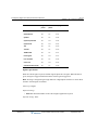
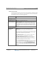
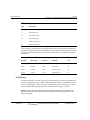
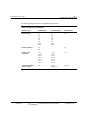
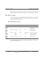
Revision History
Release
Date
2.0
09/10
Documentation Changes
Page No.
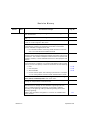
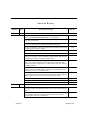
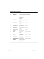
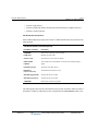
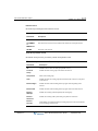
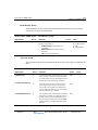
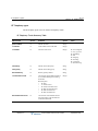
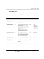
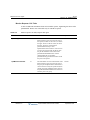
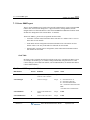
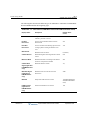
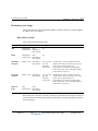
Added section “About the General Settings applet” that provides links
to information about the tasks you can accomplish via the each tab.
3-2
In section “Setting up system-wide audio options”, added information
about General HotFix 1005. This HotFix installs French, German,
Spanish, and UK English system and auto attendant voice prompts so
that you can specify the language used for prompts played to callers
and users.
4-18
Added section “Deleting a trunk group”, describing how Wave identifies
5-10
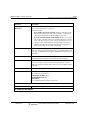
Added description of Courtesy vs. Forced reset after making changes
to digital trunk or channel configuration.
5-21
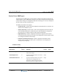
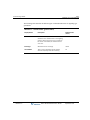
GENERAL RELEASE:
any configuration conflicts that must be resolved before a trunk group
that is still in use can be successfully deleted.
6-5
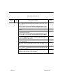
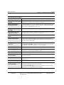
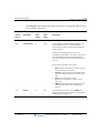
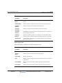
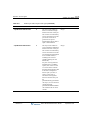
Wave now supports authentication of inbound requests for SIP
endpoints.
Updated section “DTMF transport settings“to reflect new settings.
6-46
Emergency number dialing support includes the ability to specify
9-43
multiple emergency numbers via the Outbound Routing applet.
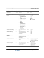
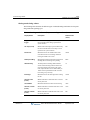
In the General Settings applet, the setting to enable or disable the
option to require an access code to dial emergency numbers has been
renamed.
16-13
The option to have Wave prompt users to enter account codes can now
be enabled on a per-user basis. (Previously, account codes could be
11-17
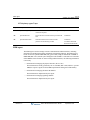
You can now use Wave Mail to synchronize a user’s voice messages
and contacts between Wave and the user’s e-mail program.
11-26
Cascading voice mail notifications—repeated notifications that a new
11-47
enabled only on a system-wide basis for all users.) When upgrading to
Wave ISM 2.0, account codes will be automatically enabled for all
users if the system-wide option had been enabled previously.
You can enable account codes for users via the Account Codes tab of
the User dialog or User Template dialog.
voice message has been received—are supported when it is critical
that voice messages are listened to and handled within a specific
period of time.
Release 2.0
September 2010
Revision History
Release
Date
Documentation Changes
Page No.
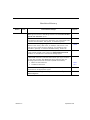
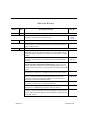
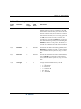
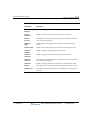
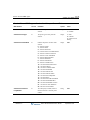
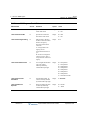
The option to Enable multiple line appearances on an analog phone is
now documented.
11-54
Imitating a Wave station on externally routed calls is supported for a
11-56
You can disable the softkeys used to make selections from the display
screen on a user’s digital or SIP phone.
11-59
DSS Console devices, associated with a user’s digital phone, provide
“switchboard” capability by expanding the number of extension
buttons available to a digital phone user.
• For information about connecting a DSS Console on a Server,
see in the Vertical Wave Installation Guide.
11-67
With the ViewPoint Softphone, included with Wave, a user can dial
numbers via the ViewPoint Softphone dial bar and answer calls via the
Call Monitor. The ViewPoint Softphone uses the PC’s microphone and
speakers, headset, or other USB audio devices for audio playback and
capture.
11-72
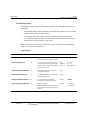
user.
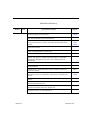
Multiple music-on-hold sources allow you to further customize the
caller experience. In addition to a system-wide default music-on-hold
source, you can now specify a music-on-hold source for the following:
• User
• User template
• Auto attendant
• Contact Center queue. See “Setting up hold music” in Chapter
2 in the Vertical Wave Contact Center Administrator’s Guide.
You can share a user’s Call Monitor, Call Log, Contact, and Message
(Inbox, Saved, and Deleted) folders with other users.
11-91
You can use user templates to quickly create new users or apply user
settings to multiple users at the same time.
11-92
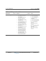
The auto attendant administrator login feature allows Wave
administrators to manage an auto attendant’s greetings over the
phone, including listening to greetings, re-recording a greeting,
recording a new greeting, making a different greeting active, and
deleting a greeting.
Added “Auto attendant configuration” to the list of available menu
choice actions.
Release 2.0
11-78
11-94
13-20
13-5
13-7
September 2010
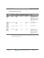
Revision History
Release
Date
Documentation Changes
Page No.
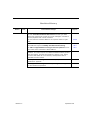
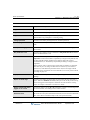
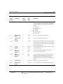
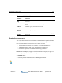
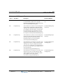
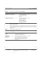
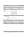
As part of auto attendant configuration, added Note to section
“Defining menu choices” describing limitations of the Process all other
digits as user extensions option.
13-12
A Transfers to scheduled action for an auto attendant menu choice can
now transfer a call to a hunt group. (Previously, you could transfer calls
to another auto attendant, user, queue, or ViewPoint group.)
13-16
You can record multiple greetings for an auto attendant—for use at
different times of day, after hours, on holidays, and so forth—and
make any one of them the active greeting. You manage an auto
attendant’s greetings via the Auto Attendant dialog - Audio tab.
13-20
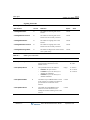
Music on hold for IP calls is supported. To play music on hold to calls
on SIP phones and SIP trunks, select the Support IP Music On Hold
16-16
checkbox on the PBX tab of the General Settings applet.
Due to new resource types being added in this version, after upgrading
to Wave ISM 2.0 from a previous version when you log on to Wave
you may see a System Alert Messages dialog indicating that the
following system resources have been updated automatically:
• Music on Hold resources
• Call Record resources
Release 2.0
16-21
19-7
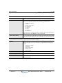
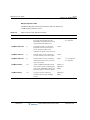
Updated section “Enabling automatic phone relocation” to include
instructions for all digital phone types.
16-25
Added section “Enabling DSS/BLF updates when the user’s phone is
active on any line”.
16-27
September 2010
Revision History
Release
Date
Documentation Changes
Page No.
Wave IMpulse supports instant messaging in ViewPoint.
•
•
•
•
You enable/disable the Instant Messaging server via the System
tab in the General Settings applet.
To access the Wave IMpulse administrator console, start the
Wave IMpulse applet, located on the Applications tab in the
Global Manager Administrator Console.
The Wave permissions Allow Instant Messaging and Allow
inter-organizational Instant Messaging) control a user’s ability to
send and receive instant messages via ViewPoint. You can
apply these permissions to an individual user (User dialog Security \ Permissions tab), to all users who are members of a
role (Role dialog - Permissions tab), or to all users based on a
user template (User Templates
dialog - Security \ Permissions tab).
To send and receive instant messages in ViewPoint, see
Chapter 4 in the Vertical Wave ViewPoint User’s Guide.
16-43
11-84,
11-106,
11-94
A new Call Record resource type is now available. Two Call Record
resources support call recording on a 2-party call. (For 3-party calls,
one Ad-Hoc Conferencing resource is used per party in the call to
support call recording, as in previous versions.)
19-6
Removed references in Chapter 22 to emergency calls being logged to
the Wave Event Log. (This feature is not supported in this version.)
---
The Software Upgrade applet now offers two new and faster upload
options, Network share and Removable drive.
23-6
Scalable call recording replaces the call recording implementation used
in previous versions. Scalable call recording off-loads the bulk of call
recording audio processing to the VAM, reducing the DSP load required
for processing large numbers of simultaneous call recordings. Also, the
call recording mixing algorithm has been optimized to avoid
unnecessary signal attenuation when recording 2-party calls.
To use scalable call recording, you must first allocate adequate Call
Record resources via the Resource Management applet.
For examples of how to estimate the number of Call Record resources
required, see “Call recordings and DSP resources”. Note that a Prompt
Assist DSP resource is no longer required to play reminder beeps while
recording a queue call.
The new Call Record resource has been added to the “System resource
types” table.
Release 2.0
16-41
16-42
23-42
19-6
23-49
September 2010
Revision History
Release
Date
Documentation Changes
Page No.
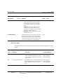
Automatic gain control (AGC) of voice mail recordings is supported via
the new Voice Mail w/Automatic Gain Control resource type. AGC
adjusts the volume level of audio as a voice message is recorded so
that the playback level is more consistent.
The new resource has been added to the “System resource types”
table.
New licenses are required in Wave ISM 2.0. See the important note.
Wave ISM 2.0 supports scalability and edition-based licensing.
The table of supported Wave license types has been updated with the
new license titles introduced in Wave ISM 2.0.
Release 2.0
23-49
24-1
24-3
24-4
You generate the new License Status report using the Report
Generator. This report reports on all Wave installed licenses by product
name and version, and lists the license key, quantity, type, status,
activation date (blank for a trial license), and expiration date (if
applicable) for each license.
31-25
Added Openfire License Agreements to “Third-party Software License
Agreements” appendix.
C-1
Added Appendix describing Wave Server port usage and configuration
for various Wave components.
E-1
September 2010
Revision History
Release
Date
1.5 SP3
09/09
Documentation Changes
Page No.
SERVICE PACK RELEASE:
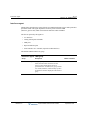
Added security warning when you are configuring an SCP concerning
setting the Tandem access profile field to “Unrestricted”.
6-12
The maximum value for the SCP route step timeout has been increased
from 9 to 30 seconds.
6-19
Added section “Dialing phone numbers entered in the ViewPoint dial
bar exactly as entered” to support EU dialing requirements.
9-41
Using 112 emergency service with Wave (EU systems) is now covered
in “Setting up emergency dialing”.
9-43
Expanded description of the Centrex Flash feature button.
10-17
Added an example of an Input Users CSV file.
1.5 SP2
06/09
Release 2.0
11-103
Updated section “About backing up your system configuration” with
Caution on the need to reset IP Address, Subnet Mask, and Gateway
settings if you restore to a different Wave Server.
15-1
Added section “Special backup/restore considerations on a WaveNet
node” that contains important information about backing up and
restoring a system configuration on a Wave Server that is a node in a
WaveNet network.
15-3
Updated section “Mirroring your hard drive” with information about the
Initialize and Convert Disk Wizard, which starts automatically if the
disk that you insert is completely blank.
15-6
Expanded section “Configuring virtual extensions” to describe how
existing SIP station IDs will change after upgrading to Wave ISM 1.5
SP2 or higher, due to how system resources are allocated.
16-36
Added section “Including a reminder beep on queue call recordings”.
19-12
Added new chapter, “Configuring Wave Servers via WaveNet”.
25-1
Added new chapter, “Using the Call Classifier”.
26-1
SERVICE PACK RELEASE:
Added section “Suppressing ringing on any digital phone that is
receiving a page” that describes a new setting in the General Settings
applet.
3-11
Added section “Recommended minimum password security settings”
that describes password security settings that are now applied
automatically for all new installations.
4-13
September 2010
Revision History
Release
Date
Documentation Changes
Page No.
Added section “Customizing AC impedance settings on analog trunk
ports” that describes settings that can be used to correct echo return
loss problems.
5-18
These are expert settings that should not be modified unless you are
directed to do so by your Vertical Technical Support representative.
Added section “Configuring ports and channels on the Quad BRI
Module”.
Added descriptions of T1, T2, and T3 advanced SIP telephony settings
for informational purposes.
5-36
6-4
These are expert settings that should not be modified unless you are
directed to do so by your Vertical Technical Support representative.
Expanded description of required user behavior if you do not specify
the optional Extension setting when configuring the Directed Park
feature for digital and SIP phones.
10-18
Added section “Importing users via a CSV file” that describes how to
import users in bulk.
11-99
You can now enable the option Show ‘All’ tab in ViewPoint Extensions
view at the role level. Previously, this option could only be set for a
11-111
Added section “About Voice Mail Distribution Groups” that describes
how to create a Voice Mail Distribution Group and how send a voice
message to its members.
12-2
Added section “When a call may be disconnected automatically” that
describes behavior when a caller does not press a key during 3
consecutive jumps between auto attendants.
13-7
user.
Release 2.0
September 2010
Revision History
Release
Date
1.5 SP1
02/09
Documentation Changes
Page No.
SERVICE PACK RELEASE:
Added sections on how to configure fax redirect, automatic phone
relocation, and call return for external calls.
1.5
01/09
GENERAL RELEASE (IP 500):
The Wave IP 500 Server is now supported. Unless otherwise specified,
the information in this manual applies to both the Wave IP 500 and
Wave IP 2500 Servers.
1.5
11/08
---
GENERAL RELEASE:
The term “Wave Server” now refers to the physical server PC on which
Wave ISM runs. When information applies to a specific Wave Server
model, the model is identified, for example “Wave IP 2500” or “Wave
IP 500”.
throughout
Expanded sections covering starting, using, and exiting dialog applets
and remote access applets in the Global Administrator Management
Console.
starting on
page 2-5
Documented the new System Settings field Limit the number of
external calls that can be routed to simultaneously, used to limit the
number of external numbers that can be called simultaneously by a
ViewPoint routing list action, in order to avoid consuming all Wave ISM
trunks.
4-5
Removed the chapter “Configuring Outside Lines” and incorporated
the material into Chapter 5, “Configuring Analog and Digital Trunks”.
5-2
Updated and expanded information on configuring Vertical-branded SIP
phones, including the Aastra 5-series SIP phones that are now
supported. See sections “Configuring SIP phone extensions” and
“Configuring Vertical-branded SIP phones”.
starting on
page 6-23
Updated IP telephony codec configuration guidelines to recommend
use of G.711U codec only in most implementations.
6-29
Added note about an important Media Resource Module (MRM)
requirement to “WAN Quality Of Service settings” section.
6-47
Added a summary table in section “Available digital and SIP phone
features” that lists all features that can be assigned to phone feature
buttons, identifying which features can be assigned on digital phones,
IP phones, or both.
Release 2.0
16-15,
16-25,
16-28
10-10
September 2010
Revision History
Release
Date
Documentation Changes
Page No.
Expanded information about the interaction of the Call Appearance and
Call Waiting digital phone features.
10-14,
10-16
Expanded section on how to configure a Direct Station Select/Busy
Lamp Field (DSS?BLP) phone feature button.
10-17
Documented how to use the Call Navigator Pickup Group n parameter
of the Line Appearance, Primary, and Queue Status digital phone
features.
10-14,
10-26,
10-29
Updated description of optional parameters for the System Speed Dial
digital phone feature.
10-34
Added information about how the ability to enable the Call Waiting
feature varies depending on phone type.
11-53
Added section “The Phone \ Ring Patterns tab”.
11-71
Terminology change: “Workgroups” are now called “ViewPoint
Groups”. The applet to manage ViewPoint Groups in the Global
Administrator Management Console is now called User/Group
Management.
The Fax Redirect feature is now supported and documented.
16-15
The System Call Record (“record all calls”) feature is now supported
and documented.
19-1
Updated section “How users enter account codes” to reflect all
supported methods.
20-11
Expanded section “Reporting ViewPoint problems”, including adding a
new section on how to flag problem calls from the ViewPoint Call
Monitor.
22-50,
22-52
Added instructions on how to use the new Resource Management
Advisor.
23-44
Microsoft Uptime utility is now documented as part of section
“Accessing Diagnostic Tools”.
23-53
Relocated and expanded information on how to add and activate Wave
licenses from Chapter 23 to new Chapter 24.
Chapter 33 (“Service Confirmation Letters and Provisioning
Information Forms”) is now Appendix C.
Release 2.0
12-1
24-1
B-1
September 2010
Revision History
Release
Date
1.0 SP2
02/08
1.0 SP1
1.0
12/07
10/07
Release 2.0
Documentation Changes
Page No.
SERVICE PACK RELEASE:
Updated the list of digital phone features to include more information
on feature settings, including the Headset command setting to support
Bluetooth headsets.
10-20
Expanded instructions on how to use the Button List in the Phone \
Station Features tab of the User dialog to assign features to a user’s
digital or IP phone.
11-65
Documented how to create Outside Lines for use with digital phones.
5-2
Added instructions on how to change the Wave Server system locale
to support non-North American locations.
33-1
SERVICE PACK RELEASE:
A Proxy Activation server option has been added to the Software
Licenses applet.
24-19
Fax Redirect settings have been added to the General Settings applet.
16-15
The Phone \ Station Features tab of the User dialog in the User/Group
Management applet has new documentation.
11-65
Ring No Answer (RNA) and Busy No Answer (BNA) configuration
settings for have been added to the Phone \ Call handling tab of the
User dialog.
11-61
Span Multiple Call Appearance settings have been added to the Station
Hunt Group dialog.
10-45
INITIAL RELEASE
September 2010
Contents
PART 1
Initial Configuration and Administration
Chapter 1.
About This Guide
About Wave ISM . . . . . . . . . . . . . . . . . . . . . . . . . . . . . . . . . . . . . . . . . . . . . . . . . 1-1
Getting the most out of this guide . . . . . . . . . . . . . . . . . . . . . . . . . . . . . . . . . . . . 1-1
Where to start . . . . . . . . . . . . . . . . . . . . . . . . . . . . . . . . . . . . . . . . . . . . . . . . . . . 1-2
For new Wave system administrators . . . . . . . . . . . . . . . . . . . . . . . . . . . . . . 1-2
For experienced Wave system administrators . . . . . . . . . . . . . . . . . . . . . . . 1-3
Using the Help system . . . . . . . . . . . . . . . . . . . . . . . . . . . . . . . . . . . . . . . . . . . . . 1-3
Conventions used in this guide . . . . . . . . . . . . . . . . . . . . . . . . . . . . . . . . . . . . . .
Special messages . . . . . . . . . . . . . . . . . . . . . . . . . . . . . . . . . . . . . . . . . . . . .
Type conventions . . . . . . . . . . . . . . . . . . . . . . . . . . . . . . . . . . . . . . . . . . . . .
Terms used . . . . . . . . . . . . . . . . . . . . . . . . . . . . . . . . . . . . . . . . . . . . . . . . . .
1-3
1-3
1-4
1-4
Related reading . . . . . . . . . . . . . . . . . . . . . . . . . . . . . . . . . . . . . . . . . . . . . . . . . . 1-5
Manuals . . . . . . . . . . . . . . . . . . . . . . . . . . . . . . . . . . . . . . . . . . . . . . . . . . . . 1-5
Support services . . . . . . . . . . . . . . . . . . . . . . . . . . . . . . . . . . . . . . . . . . . . . . . . . . 1-6
Web site . . . . . . . . . . . . . . . . . . . . . . . . . . . . . . . . . . . . . . . . . . . . . . . . . . . . . . . . 1-6
System security . . . . . . . . . . . . . . . . . . . . . . . . . . . . . . . . . . . . . . . . . . . . . . . . . . 1-6
Chapter 2.
Navigating the Management Console
Before logging on . . . . . . . . . . . . . . . . . . . . . . . . . . . . . . . . . . . . . . . . . . . . . . . . 2-1
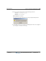
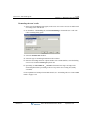
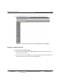
Logging on for the first time . . . . . . . . . . . . . . . . . . . . . . . . . . . . . . . . . . . . 2-2
Release 2.0
Wave Global Administrator Guide
September 2010
TOC-2
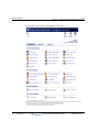
Management Console basics . . . . . . . . . . . . . . . . . . . . . . . . . . . . . . . . . . . . . . . 2-5
Starting and exiting applets . . . . . . . . . . . . . . . . . . . . . . . . . . . . . . . . . . . . . . . . 2-5
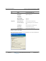
Dialog applets vs. remote access applets . . . . . . . . . . . . . . . . . . . . . . . . . . . .2-5
Dialog applets . . . . . . . . . . . . . . . . . . . . . . . . . . . . . . . . . . . . . . . . . . . . . . . .2-6
Remote access applets . . . . . . . . . . . . . . . . . . . . . . . . . . . . . . . . . . . . . . . . . .2-7
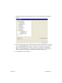
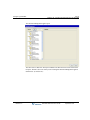
Navigating applet tree structures . . . . . . . . . . . . . . . . . . . . . . . . . . . . . . . . . . . 2-10
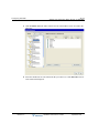
Displaying and hiding items in a tree . . . . . . . . . . . . . . . . . . . . . . . . . . . . .2-11
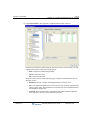
Selecting items in a tree . . . . . . . . . . . . . . . . . . . . . . . . . . . . . . . . . . . . . . . .2-13
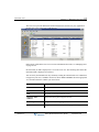
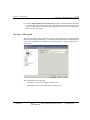
Using the User/Group Management applet . . . . . . . . . . . . . . . . . . . . . . . . . . . 2-13
Accessing the User/Group Management applet . . . . . . . . . . . . . . . . . . . . .2-14
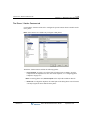
The User/Group Management applet interface . . . . . . . . . . . . . . . . . . . . . .2-15
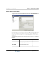
Using the Tools menu . . . . . . . . . . . . . . . . . . . . . . . . . . . . . . . . . . . . . . . . .2-16
Working in views . . . . . . . . . . . . . . . . . . . . . . . . . . . . . . . . . . . . . . . . . . . . .2-17
Using commands in a view . . . . . . . . . . . . . . . . . . . . . . . . . . . . . . . . . . . . .2-18
Using the User/Group Management applet toolbar . . . . . . . . . . . . . . . . . . .2-18
Customizing columns . . . . . . . . . . . . . . . . . . . . . . . . . . . . . . . . . . . . . . . . .2-19
Working with voice files . . . . . . . . . . . . . . . . . . . . . . . . . . . . . . . . . . . . . . .2-19
Using the audio controls . . . . . . . . . . . . . . . . . . . . . . . . . . . . . . . . . . . . . . .2-20
Importing and exporting voice files . . . . . . . . . . . . . . . . . . . . . . . . . . . . . .2-21
Chapter 3.
Before You Begin
Before you begin . . . . . . . . . . . . . . . . . . . . . . . . . . . . . . . . . . . . . . . . . . . . . . . . 3-1
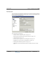
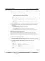
About the General Settings applet . . . . . . . . . . . . . . . . . . . . . . . . . . . . . . . . . . . 3-2
Entering basic system information . . . . . . . . . . . . . . . . . . . . . . . . . . . . . . . . . . . 3-4
Verifying installed components . . . . . . . . . . . . . . . . . . . . . . . . . . . . . . . . . . . . . 3-6
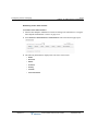
Adding accounts and passwords . . . . . . . . . . . . . . . . . . . . . . . . . . . . . . . . . . . . . 3-8
Configuring access permissions . . . . . . . . . . . . . . . . . . . . . . . . . . . . . . . . . .3-9
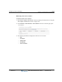
Setting the message-waiting dial tone duration . . . . . . . . . . . . . . . . . . . . . . . . 3-10
Suppressing ringing on any digital phone that is receiving a page . . . . . . . . . 3-11
Configuring the time service . . . . . . . . . . . . . . . . . . . . . . . . . . . . . . . . . . . . . . 3-11
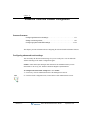
Chapter 4.
System Settings in the User/Group Management applet
Opening the System Settings dialog . . . . . . . . . . . . . . . . . . . . . . . . . . . . . . . . . . 4-1
Release 2.0
Wave Global Administrator Guide
September 2010
TOC-3
Documentation for the System Settings dialog . . . . . . . . . . . . . . . . . . . . . . 4-2
Setting general options . . . . . . . . . . . . . . . . . . . . . . . . . . . . . . . . . . . . . . . . . . . . 4-4
Setting general Wave settings . . . . . . . . . . . . . . . . . . . . . . . . . . . . . . . . . . . . 4-4
Configuring the dial-by-name directory . . . . . . . . . . . . . . . . . . . . . . . . . . . . 4-6
Setting business hours . . . . . . . . . . . . . . . . . . . . . . . . . . . . . . . . . . . . . . . . . . . . 4-9
Defining business hours . . . . . . . . . . . . . . . . . . . . . . . . . . . . . . . . . . . . . . . . 4-9
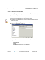
Setting up e-mail notification . . . . . . . . . . . . . . . . . . . . . . . . . . . . . . . . . . . . . . 4-12
Enabling e-mail notification . . . . . . . . . . . . . . . . . . . . . . . . . . . . . . . . . . . . 4-12
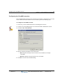
Configuring users for e-mail notification . . . . . . . . . . . . . . . . . . . . . . . . . . 4-13
Enforcing strong password security . . . . . . . . . . . . . . . . . . . . . . . . . . . . . . . . . 4-13
Recommended minimum password security settings . . . . . . . . . . . . . . . . 4-13
Setting up system-wide audio options . . . . . . . . . . . . . . . . . . . . . . . . . . . . . . . 4-18
Setting up personal call supervision defaults . . . . . . . . . . . . . . . . . . . . . . . . . . 4-20
Chapter 5.
Configuring Analog and Digital Trunks
About creating new trunk groups . . . . . . . . . . . . . . . . . . . . . . . . . . . . . . . . . . . . 5-2
About creating outside lines . . . . . . . . . . . . . . . . . . . . . . . . . . . . . . . . . . . . . 5-2
Creating a new trunk group . . . . . . . . . . . . . . . . . . . . . . . . . . . . . . . . . . . . . . . . . 5-3
Deleting a trunk group . . . . . . . . . . . . . . . . . . . . . . . . . . . . . . . . . . . . . . . . . . . . 5-10
Configuring trunks and channels . . . . . . . . . . . . . . . . . . . . . . . . . . . . . . . . . . . . 5-13
Trunk and channel settings . . . . . . . . . . . . . . . . . . . . . . . . . . . . . . . . . . . . . 5-13
Release 2.0
Configuring analog trunks . . . . . . . . . . . . . . . . . . . . . . . . . . . . . . . . . . . . . . . . .
Configuring analog trunk card or module settings . . . . . . . . . . . . . . . . . . .
Configuring analog channels . . . . . . . . . . . . . . . . . . . . . . . . . . . . . . . . . . .
Customizing AC impedance settings on analog trunk ports . . . . . . . . . . .
5-14
5-15
5-16
5-18
Configuring digital trunks and channels . . . . . . . . . . . . . . . . . . . . . . . . . . . . . .
Configuring digital trunk card or module settings . . . . . . . . . . . . . . . . . . .
Configuring digital channels . . . . . . . . . . . . . . . . . . . . . . . . . . . . . . . . . . .
Configuring digital channels for data . . . . . . . . . . . . . . . . . . . . . . . . . . . . .
Configuring digital channels for ISDN . . . . . . . . . . . . . . . . . . . . . . . . . . .
Assigning digital channels to a serial interface . . . . . . . . . . . . . . . . . . . . .
Configuring ports and channels on the Quad BRI Module . . . . . . . . . . . .
5-21
5-22
5-29
5-33
5-34
5-35
5-36
Wave Global Administrator Guide
September 2010
TOC-4
Enabling trunks for external pager and call notifications . . . . . . . . . . . . . . . . . 5-41
Chapter 6
IP Telephony Configuration
Allocating IP telephony resources . . . . . . . . . . . . . . . . . . . . . . . . . . . . . . . . . . . 6-1
Configuring site-to-site call routing for IP telephony . . . . . . . . . . . . . . . . . . . . 6-3
Enabling IP telephony or SIP signaling protocols . . . . . . . . . . . . . . . . . . . . .6-3
Setting up SIP endpoint authentication . . . . . . . . . . . . . . . . . . . . . . . . . . . . .6-5
Configuring Signaling Control Points . . . . . . . . . . . . . . . . . . . . . . . . . . . . . .6-9
Configuring default inbound IP call routing . . . . . . . . . . . . . . . . . . . . . . . .6-20
Including Signaling Control Points in the outbound call routing configuration
6-21
Configuring SIP phones . . . . . . . . . . . . . . . . . . . . . . . . . . . . . . . . . . . . . . . . . . 6-22
Configuring SIP phone extensions . . . . . . . . . . . . . . . . . . . . . . . . . . . . . . .6-23
Configuring Vertical-branded SIP phones . . . . . . . . . . . . . . . . . . . . . . . . . .6-25
Enabling IP call bandwidth . . . . . . . . . . . . . . . . . . . . . . . . . . . . . . . . . . . . .6-28
Changing the password for the IPPhone user account . . . . . . . . . . . . . . . .6-28
Configuring bandwidth management zones . . . . . . . . . . . . . . . . . . . . . . . . . . . 6-28
Zone configuration recommendations . . . . . . . . . . . . . . . . . . . . . . . . . . . . .6-29
Codec negotiation . . . . . . . . . . . . . . . . . . . . . . . . . . . . . . . . . . . . . . . . . . . .6-30
Configuring the home zone . . . . . . . . . . . . . . . . . . . . . . . . . . . . . . . . . . . . .6-30
Configuring remote zones . . . . . . . . . . . . . . . . . . . . . . . . . . . . . . . . . . . . . .6-35
Configuring the remote default zone . . . . . . . . . . . . . . . . . . . . . . . . . . . . . .6-37
Adjusting IP call quality parameters . . . . . . . . . . . . . . . . . . . . . . . . . . . . . . . . 6-39
Jitter buffer . . . . . . . . . . . . . . . . . . . . . . . . . . . . . . . . . . . . . . . . . . . . . . . . .6-39
Echo cancellation . . . . . . . . . . . . . . . . . . . . . . . . . . . . . . . . . . . . . . . . . . . . .6-41
Comfort noise . . . . . . . . . . . . . . . . . . . . . . . . . . . . . . . . . . . . . . . . . . . . . . .6-43
Gain . . . . . . . . . . . . . . . . . . . . . . . . . . . . . . . . . . . . . . . . . . . . . . . . . . . . . . .6-44
DTMF transport settings . . . . . . . . . . . . . . . . . . . . . . . . . . . . . . . . . . . . . . .6-46
Quality Of Service (QoS) settings . . . . . . . . . . . . . . . . . . . . . . . . . . . . . . . .6-47
IP telephony ports . . . . . . . . . . . . . . . . . . . . . . . . . . . . . . . . . . . . . . . . . . . . . . . 6-49
Chapter 7.
Initial Call Routing Configuration
About the First Digit Table . . . . . . . . . . . . . . . . . . . . . . . . . . . . . . . . . . . . . . . . . 7-1
Configuring extension ranges . . . . . . . . . . . . . . . . . . . . . . . . . . . . . . . . . . . . . . . 7-3
Release 2.0
Wave Global Administrator Guide
September 2010
TOC-5
Setting the home area code . . . . . . . . . . . . . . . . . . . . . . . . . . . . . . . . . . . . . . . . . 7-5
Configuring 10-digit dialing . . . . . . . . . . . . . . . . . . . . . . . . . . . . . . . . . . . . . . . . 7-6
Configuring the VoiceMail extension . . . . . . . . . . . . . . . . . . . . . . . . . . . . . . . . . 7-7
Chapter 8.
Configuring Inbound Call Routing
Configuring trunk groups for inbound call routing . . . . . . . . . . . . . . . . . . . . . . . 8-1
Configuring inbound routing tables . . . . . . . . . . . . . . . . . . . . . . . . . . . . . . . . . . . 8-4
Chapter 9.
Configuring Outbound Call Routing
Configuring automatic route selection . . . . . . . . . . . . . . . . . . . . . . . . . . . . . . . . 9-1
Configuring the external first digit . . . . . . . . . . . . . . . . . . . . . . . . . . . . . . . . 9-2
Configuring the Global Access Profile . . . . . . . . . . . . . . . . . . . . . . . . . . . . 9-4
Configuring specific access profiles . . . . . . . . . . . . . . . . . . . . . . . . . . . . . 9-14
Configuring outbound routing tables . . . . . . . . . . . . . . . . . . . . . . . . . . . . . 9-20
Configuring off-premise extension routing . . . . . . . . . . . . . . . . . . . . . . . . . . . . 9-22
Creating off-premise extension ranges . . . . . . . . . . . . . . . . . . . . . . . . . . . . 9-23
Configuring the off-premise extension table . . . . . . . . . . . . . . . . . . . . . . . 9-23
Configuring destination access code routing . . . . . . . . . . . . . . . . . . . . . . . . . . . 9-25
Creating destination access codes . . . . . . . . . . . . . . . . . . . . . . . . . . . . . . . 9-26
Enabling destination access codes . . . . . . . . . . . . . . . . . . . . . . . . . . . . . . . 9-27
Configuring private networking . . . . . . . . . . . . . . . . . . . . . . . . . . . . . . . . . . . .
Determining a numbering scheme for private networking . . . . . . . . . . . . .
Configuring outbound routing for private networking . . . . . . . . . . . . . . . .
Configuring the First Digit Table for private networking . . . . . . . . . . . . .
Enabling the new destination access code . . . . . . . . . . . . . . . . . . . . . . . . .
9-29
9-29
9-30
9-33
9-37
Changing an access code in a user’s saved numbers . . . . . . . . . . . . . . . . . . . . . 9-39
Setting default access codes for callbacks . . . . . . . . . . . . . . . . . . . . . . . . . . . . . 9-40
Where the default access codes are displayed . . . . . . . . . . . . . . . . . . . . . . 9-41
Dialing phone numbers entered in the ViewPoint dial bar exactly as entered . 9-41
Setting up emergency dialing . . . . . . . . . . . . . . . . . . . . . . . . . . . . . . . . . . . . . . 9-43
Defining emergency numbers . . . . . . . . . . . . . . . . . . . . . . . . . . . . . . . . . . 9-43
Release 2.0
Wave Global Administrator Guide
September 2010
TOC-6
Chapter 10.
Configuring Phones
About phone templates . . . . . . . . . . . . . . . . . . . . . . . . . . . . . . . . . . . . . . . . . . . 10-2
Configuring phone templates . . . . . . . . . . . . . . . . . . . . . . . . . . . . . . . . . . .10-2
Customizing analog phone templates . . . . . . . . . . . . . . . . . . . . . . . . . . . . .10-4
Customizing digital and SIP phone templates . . . . . . . . . . . . . . . . . . . . . . .10-6
Configuring digital and SIP phone feature buttons . . . . . . . . . . . . . . . . . . . . 10-10
Available digital and SIP phone features . . . . . . . . . . . . . . . . . . . . . . . . . .10-10
Configuring hunt groups of extensions . . . . . . . . . . . . . . . . . . . . . . . . . . . . . 10-40
Configuring the Attendant hunt group . . . . . . . . . . . . . . . . . . . . . . . . . . .10-41
Creating a station hunt group . . . . . . . . . . . . . . . . . . . . . . . . . . . . . . . . . .10-45
Enabling and disabling station ports . . . . . . . . . . . . . . . . . . . . . . . . . . . . . . . . 10-48
Chapter 11.
Managing Users and Roles
How to set user options . . . . . . . . . . . . . . . . . . . . . . . . . . . . . . . . . . . . . . . . . . 11-2
How to add users . . . . . . . . . . . . . . . . . . . . . . . . . . . . . . . . . . . . . . . . . . . . . . . 11-3
The Admin user . . . . . . . . . . . . . . . . . . . . . . . . . . . . . . . . . . . . . . . . . . . . . .11-3
Adding users on a Wave IP 500 Server . . . . . . . . . . . . . . . . . . . . . . . . . . . .11-3
Increasing the number of digital phone users on a Wave IP 500 Server . . .11-4
The Users view . . . . . . . . . . . . . . . . . . . . . . . . . . . . . . . . . . . . . . . . . . . . . . . . . 11-4
Archiving a user’s voicemail and call recordings . . . . . . . . . . . . . . . . . . . .11-7
Deleting a user . . . . . . . . . . . . . . . . . . . . . . . . . . . . . . . . . . . . . . . . . . . . . . .11-8
Adding users via the User dialog . . . . . . . . . . . . . . . . . . . . . . . . . . . . . . . . . . . 11-9
The User tab. . . . . . . . . . . . . . . . . . . . . . . . . . . . . . . . . . . . . . . . . . . . . . . . . . . 11-12
Assigning a user from a digital phone . . . . . . . . . . . . . . . . . . . . . . . . . . . .11-15
The User \ Details tab . . . . . . . . . . . . . . . . . . . . . . . . . . . . . . . . . . . . . . . . . . . 11-16
Entering comments . . . . . . . . . . . . . . . . . . . . . . . . . . . . . . . . . . . . . . . . . .11-16
Setting up a personal operator . . . . . . . . . . . . . . . . . . . . . . . . . . . . . . . . . .11-17
Entering the user’s Microsoft Windows NT account . . . . . . . . . . . . . . . .11-17
The User \ Account Codes tab . . . . . . . . . . . . . . . . . . . . . . . . . . . . . . . . . . . . 11-17
The User \ Call Log tab . . . . . . . . . . . . . . . . . . . . . . . . . . . . . . . . . . . . . . . . . 11-19
Determining which calls are logged . . . . . . . . . . . . . . . . . . . . . . . . . . . . .11-20
Associating the user with an Organization . . . . . . . . . . . . . . . . . . . . . . . .11-20
Release 2.0
Wave Global Administrator Guide
September 2010
TOC-7
The User \ External Caller ID tab . . . . . . . . . . . . . . . . . . . . . . . . . . . . . . . . . . 11-21
The User \ Numbers tab . . . . . . . . . . . . . . . . . . . . . . . . . . . . . . . . . . . . . . . . . . 11-22
The Voice Mail tab . . . . . . . . . . . . . . . . . . . . . . . . . . . . . . . . . . . . . . . . . . . . . 11-24
Configuring the user’s voice mailbox . . . . . . . . . . . . . . . . . . . . . . . . . . . 11-25
Choosing the mailbox for call recordings . . . . . . . . . . . . . . . . . . . . . . . . 11-25
Enabling voicemail greeting logon . . . . . . . . . . . . . . . . . . . . . . . . . . . . . 11-25
Synchronizing a user’s Wave voice messages and contacts with the user’s
e-mail program . . . . . . . . . . . . . . . . . . . . . . . . . . . . . . . . . . . . . . . . . . . . . 11-26
The Voice Mail \ E-mail, Pager, and Call Notification tabs . . . . . . . . . . . . . .
Notification information . . . . . . . . . . . . . . . . . . . . . . . . . . . . . . . . . . . . . .
Determining which voice messages send notification . . . . . . . . . . . . . . .
Setting e-mail notification . . . . . . . . . . . . . . . . . . . . . . . . . . . . . . . . . . . .
Setting pager notification . . . . . . . . . . . . . . . . . . . . . . . . . . . . . . . . . . . . .
Setting call notification . . . . . . . . . . . . . . . . . . . . . . . . . . . . . . . . . . . . . .
Scheduling notifications . . . . . . . . . . . . . . . . . . . . . . . . . . . . . . . . . . . . . .
Defining a schedule for notifications . . . . . . . . . . . . . . . . . . . . . . . . . . . .
Setting up custom hours . . . . . . . . . . . . . . . . . . . . . . . . . . . . . . . . . . . . . .
11-35
11-36
11-37
11-38
11-39
11-41
11-42
11-43
11-45
The Voice Mail \ Cascading Notifications tab . . . . . . . . . . . . . . . . . . . . . . . . . 11-47
The Phone tab . . . . . . . . . . . . . . . . . . . . . . . . . . . . . . . . . . . . . . . . . . . . . . . . . 11-51
Setting the number of rings for the phone . . . . . . . . . . . . . . . . . . . . . . . . 11-52
Having the phone automatically dial when taken off hook . . . . . . . . . . . 11-52
Using call waiting . . . . . . . . . . . . . . . . . . . . . . . . . . . . . . . . . . . . . . . . . . . 11-53
Enabling multiple line appearances on an analog phone . . . . . . . . . . . . . 11-54
Dropping loop current when idle on an analog phone . . . . . . . . . . . . . . . 11-55
Supplying a SIP authentication password . . . . . . . . . . . . . . . . . . . . . . . . 11-56
Using mobile extensions and imitating a station on externally routed calls . . .
11-56
Automatically going off-hook when alerting . . . . . . . . . . . . . . . . . . . . . . 11-58
Sending digits to an analog phone . . . . . . . . . . . . . . . . . . . . . . . . . . . . . . 11-58
Disabling softkeys on a digital phone . . . . . . . . . . . . . . . . . . . . . . . . . . . 11-59
Configuring Flash behavior on an analog phone . . . . . . . . . . . . . . . . . . . 11-59
The Phone \ Call Handling tab . . . . . . . . . . . . . . . . . . . . . . . . . . . . . . . . . . . . 11-60
Configuring actions for unanswered or busy calls . . . . . . . . . . . . . . . . . . 11-61
Forwarding the user’s calls . . . . . . . . . . . . . . . . . . . . . . . . . . . . . . . . . . . 11-63
Release 2.0
Wave Global Administrator Guide
September 2010
TOC-8
The Phone \ Station Features tab . . . . . . . . . . . . . . . . . . . . . . . . . . . . . . . . . . 11-65
The Phone \ DSS Consoles tab . . . . . . . . . . . . . . . . . . . . . . . . . . . . . . . . . . . . 11-67
The Phone \ Ring Patterns tab . . . . . . . . . . . . . . . . . . . . . . . . . . . . . . . . . . . . 11-71
The Phone \ Softphone tab . . . . . . . . . . . . . . . . . . . . . . . . . . . . . . . . . . . . . . . 11-72
The Phone \ Automatic Log Out tab . . . . . . . . . . . . . . . . . . . . . . . . . . . . . . . . 11-74
The Audio tab . . . . . . . . . . . . . . . . . . . . . . . . . . . . . . . . . . . . . . . . . . . . . . . . . 11-76
Setting the storage size for greetings and voice titles . . . . . . . . . . . . . . . .11-76
Choosing a language for phone prompts . . . . . . . . . . . . . . . . . . . . . . . . . .11-77
The Audio \ Hold Music, Voice Title, and Disk Usage tabs . . . . . . . . . . . . . . 11-77
Setting the user’s hold music . . . . . . . . . . . . . . . . . . . . . . . . . . . . . . . . . . .11-78
Recording the user’s voice title . . . . . . . . . . . . . . . . . . . . . . . . . . . . . . . . .11-80
Viewing the user’s disk usage . . . . . . . . . . . . . . . . . . . . . . . . . . . . . . . . . .11-81
The Security tab . . . . . . . . . . . . . . . . . . . . . . . . . . . . . . . . . . . . . . . . . . . . . . . 11-82
Configuring password expiration . . . . . . . . . . . . . . . . . . . . . . . . . . . . . . .11-82
Configuring whether the user’s calls can be supervised . . . . . . . . . . . . . .11-83
The Security \ Permissions tab . . . . . . . . . . . . . . . . . . . . . . . . . . . . . . . . . . . . 11-84
Before assigning permissions . . . . . . . . . . . . . . . . . . . . . . . . . . . . . . . . . .11-84
Assigning a user’s permissions . . . . . . . . . . . . . . . . . . . . . . . . . . . . . . . . .11-85
Changing the user’s roles . . . . . . . . . . . . . . . . . . . . . . . . . . . . . . . . . . . . .11-86
The Queue \ Attributes tab . . . . . . . . . . . . . . . . . . . . . . . . . . . . . . . . . . . . . . . 11-87
The Queue\ Skills tab . . . . . . . . . . . . . . . . . . . . . . . . . . . . . . . . . . . . . . . . . . . 11-88
The Dial-by-name Directory tab . . . . . . . . . . . . . . . . . . . . . . . . . . . . . . . . . . . 11-89
The ViewPoint tab . . . . . . . . . . . . . . . . . . . . . . . . . . . . . . . . . . . . . . . . . . . . . 11-90
The Sharing tab . . . . . . . . . . . . . . . . . . . . . . . . . . . . . . . . . . . . . . . . . . . . . . . . 11-91
Creating and updating users via a user template . . . . . . . . . . . . . . . . . . . . . . 11-92
About the User Template dialog . . . . . . . . . . . . . . . . . . . . . . . . . . . . . . . .11-93
Creating a new user template . . . . . . . . . . . . . . . . . . . . . . . . . . . . . . . . . .11-96
Adding users via a user template . . . . . . . . . . . . . . . . . . . . . . . . . . . . . . . .11-98
Applying user settings in bulk . . . . . . . . . . . . . . . . . . . . . . . . . . . . . . . . . .11-98
Importing users via a CSV file . . . . . . . . . . . . . . . . . . . . . . . . . . . . . . . . . . . . 11-99
Import Users CSV file format . . . . . . . . . . . . . . . . . . . . . . . . . . . . . . . . .11-100
Release 2.0
Wave Global Administrator Guide
September 2010
TOC-9
Managing roles . . . . . . . . . . . . . . . . . . . . . . . . . . . . . . . . . . . . . . . . . . . . . . .
Assigning users to a role . . . . . . . . . . . . . . . . . . . . . . . . . . . . . . . . . . . .
Editing a role . . . . . . . . . . . . . . . . . . . . . . . . . . . . . . . . . . . . . . . . . . . . .
Creating a new role . . . . . . . . . . . . . . . . . . . . . . . . . . . . . . . . . . . . . . . .
11-104
11-105
11-105
11-106
Wave permissions . . . . . . . . . . . . . . . . . . . . . . . . . . . . . . . . . . . . . . . . . . . . . 11-109
General user permissions . . . . . . . . . . . . . . . . . . . . . . . . . . . . . . . . . . . . 11-109
Chapter 12.
Managing ViewPoint Groups
About public and personal ViewPoint Groups . . . . . . . . . . . . . . . . . . . . . . . . . 12-2
About Voice Mail Distribution Groups . . . . . . . . . . . . . . . . . . . . . . . . . . . . . . . 12-2
Benefits of using ViewPoint Groups . . . . . . . . . . . . . . . . . . . . . . . . . . . . . . . . . 12-3
The ViewPoint Groups view . . . . . . . . . . . . . . . . . . . . . . . . . . . . . . . . . . . . . . . 12-3
Creating a ViewPoint Group . . . . . . . . . . . . . . . . . . . . . . . . . . . . . . . . . . . . . . . 12-4
Chapter 13.
Configuring Auto Attendants
The Default Auto Attendant . . . . . . . . . . . . . . . . . . . . . . . . . . . . . . . . . . . . . . . 13-2
Configuring an auto attendant . . . . . . . . . . . . . . . . . . . . . . . . . . . . . . . . . . . . . . 13-3
Creating a new auto attendant . . . . . . . . . . . . . . . . . . . . . . . . . . . . . . . . . . . . . . 13-3
Defining menu choices . . . . . . . . . . . . . . . . . . . . . . . . . . . . . . . . . . . . . . . . . . . 13-5
Menu choice actions . . . . . . . . . . . . . . . . . . . . . . . . . . . . . . . . . . . . . . . . . . 13-7
Adding a menu choice . . . . . . . . . . . . . . . . . . . . . . . . . . . . . . . . . . . . . . . . 13-8
Setting general menu options . . . . . . . . . . . . . . . . . . . . . . . . . . . . . . . . . . 13-12
Customizing login behavior from auto attendants . . . . . . . . . . . . . . . . . . . . . . 13-13
Avoiding the auto attendant ambiguous dialing delay . . . . . . . . . . . . . . . . . . 13-16
Scheduling transfers and greetings . . . . . . . . . . . . . . . . . . . . . . . . . . . . . . . . . 13-16
Setting up an auto attendant’s hold music and greetings . . . . . . . . . . . . . . . . . 13-20
Setting up custom data and skill requirements for an auto attendant . . . . . . . 13-22
Viewing auto attendants in the Hunt Groups applet . . . . . . . . . . . . . . . . . . . . 13-24
Configuring the trunk group for the auto attendant extension . . . . . . . . . . . . 13-25
Configuring calls to be forwarded to the RNA forwarding target . . . . . . . . . . 13-26
Release 2.0
Wave Global Administrator Guide
September 2010
TOC-10
Chapter 14.
Data Networking Configuration
Ensuring that the T-1 serial interface is set correctly . . . . . . . . . . . . . . . . . . . . 14-1
Chapter 15.
Initial System Administration
About backing up your system configuration . . . . . . . . . . . . . . . . . . . . . . . . . . 15-1
Special backup/restore considerations on a WaveNet node . . . . . . . . . . . .15-3
Backing up your system configuration . . . . . . . . . . . . . . . . . . . . . . . . . . . . . . . 15-4
Mirroring your hard drive . . . . . . . . . . . . . . . . . . . . . . . . . . . . . . . . . . . . . . . . . 15-6
RAID cautions . . . . . . . . . . . . . . . . . . . . . . . . . . . . . . . . . . . . . . . . . . . . . .15-10
Restarting the Wave Server . . . . . . . . . . . . . . . . . . . . . . . . . . . . . . . . . . . . . . 15-11
Running Microsoft Systems Management Server . . . . . . . . . . . . . . . . . . . . . 15-12
PART 2
Advanced Configuration and Administration
Chapter 16.
PBX Feature Configuration
Configuring authorization codes . . . . . . . . . . . . . . . . . . . . . . . . . . . . . . . . . . . 16-2
Configuring Call Park options . . . . . . . . . . . . . . . . . . . . . . . . . . . . . . . . . . . . . 16-4
Configuring call pickup groups . . . . . . . . . . . . . . . . . . . . . . . . . . . . . . . . . . . . 16-5
Configuring Caller ID . . . . . . . . . . . . . . . . . . . . . . . . . . . . . . . . . . . . . . . . . . . . 16-6
Configuring external Caller ID . . . . . . . . . . . . . . . . . . . . . . . . . . . . . . . . . .16-6
Hierarchy of external Caller ID settings . . . . . . . . . . . . . . . . . . . . . . . . . . .16-7
Configuring internal Caller ID . . . . . . . . . . . . . . . . . . . . . . . . . . . . . . . . . .16-9
Configuring inbound Caller ID . . . . . . . . . . . . . . . . . . . . . . . . . . . . . . . . . .16-9
Configuring trunk-specific Caller ID settings . . . . . . . . . . . . . . . . . . . . . .16-10
Configuring system-wide Caller ID settings . . . . . . . . . . . . . . . . . . . . . . .16-11
Configuring user-specific Caller ID settings . . . . . . . . . . . . . . . . . . . . . . .16-12
Configuring dialing time-out . . . . . . . . . . . . . . . . . . . . . . . . . . . . . . . . . . . . . 16-13
Requiring an access code for emergency number dialing . . . . . . . . . . . . . . . 16-13
Configuring external call routing restrictions . . . . . . . . . . . . . . . . . . . . . . . . . 16-14
Configuring Fax Redirect . . . . . . . . . . . . . . . . . . . . . . . . . . . . . . . . . . . . . . . . 16-15
Setting Fax Redirect for an auto attendant . . . . . . . . . . . . . . . . . . . . . . . .16-16
Release 2.0
Wave Global Administrator Guide
September 2010
TOC-11
Configuring Music On Hold . . . . . . . . . . . . . . . . . . . . . . . . . . . . . . . . . . . . . . 16-16
About resource reallocation of Music-on-Hold resources after upgrading . . . .
16-21
Customizing music on hold . . . . . . . . . . . . . . . . . . . . . . . . . . . . . . . . . . . 16-23
Enabling Public Address . . . . . . . . . . . . . . . . . . . . . . . . . . . . . . . . . . . . . . . . . 16-24
Enabling automatic phone relocation . . . . . . . . . . . . . . . . . . . . . . . . . . . . . . . 16-25
Enabling DSS/BLF updates when the user’s phone is active on any line . . . . 16-27
Enabling call return for external calls . . . . . . . . . . . . . . . . . . . . . . . . . . . . . . . 16-28
Configuring Night Answer . . . . . . . . . . . . . . . . . . . . . . . . . . . . . . . . . . . . . . . 16-29
Configuring System Speed Dial . . . . . . . . . . . . . . . . . . . . . . . . . . . . . . . . . . .
Adding speed dial numbers . . . . . . . . . . . . . . . . . . . . . . . . . . . . . . . . . . .
Setting the System Speed Dial password . . . . . . . . . . . . . . . . . . . . . . . . .
Adding speed dial numbers using the phone . . . . . . . . . . . . . . . . . . . . . .
Overriding access profiles when using System Speed Dial . . . . . . . . . . .
16-31
16-31
16-33
16-34
16-35
Configuring virtual extensions . . . . . . . . . . . . . . . . . . . . . . . . . . . . . . . . . . . . 16-36
Configuring zone paging groups . . . . . . . . . . . . . . . . . . . . . . . . . . . . . . . . . . . 16-37
Configuring instant messaging . . . . . . . . . . . . . . . . . . . . . . . . . . . . . . . . . . . .
Enabling the Instant Messaging server . . . . . . . . . . . . . . . . . . . . . . . . . . .
Setting up instant messaging permissions for users . . . . . . . . . . . . . . . . .
Using the Wave IMpulse Administrator Console . . . . . . . . . . . . . . . . . . .
Chapter 17.
16-41
16-42
16-42
16-43
Advanced Trunk and Channel Configuration
Configuring advanced trunk settings . . . . . . . . . . . . . . . . . . . . . . . . . . . . . . . . . 17-1
Setting trunk timing values . . . . . . . . . . . . . . . . . . . . . . . . . . . . . . . . . . . . . . . . 17-5
Setting digital trunk timing values . . . . . . . . . . . . . . . . . . . . . . . . . . . . . . . 17-6
Setting analog trunk timing values . . . . . . . . . . . . . . . . . . . . . . . . . . . . . . . 17-9
Configuring system-wide ISDN settings . . . . . . . . . . . . . . . . . . . . . . . . . . . . . 17-12
Chapter 18.
Managing System Prompts and Audio
Presenting a confirmation prompt before voicemail . . . . . . . . . . . . . . . . . . . . . 18-1
The System Prompts view . . . . . . . . . . . . . . . . . . . . . . . . . . . . . . . . . . . . . . . . 18-2
Controlling the prompt display . . . . . . . . . . . . . . . . . . . . . . . . . . . . . . . . . 18-3
Release 2.0
Wave Global Administrator Guide
September 2010
TOC-12
Managing system prompts . . . . . . . . . . . . . . . . . . . . . . . . . . . . . . . . . . . . . . . . 18-3
Playing system prompts . . . . . . . . . . . . . . . . . . . . . . . . . . . . . . . . . . . . . . . .18-4
Exporting system prompt text . . . . . . . . . . . . . . . . . . . . . . . . . . . . . . . . . . .18-4
Exporting and importing system prompt audio files . . . . . . . . . . . . . . . . . 18-5
Recording over system prompts . . . . . . . . . . . . . . . . . . . . . . . . . . . . . . . . . . . . 18-5
Recording options . . . . . . . . . . . . . . . . . . . . . . . . . . . . . . . . . . . . . . . . . . . .18-6
About the recording process . . . . . . . . . . . . . . . . . . . . . . . . . . . . . . . . . . . .18-6
Recording system prompts professionally . . . . . . . . . . . . . . . . . . . . . . . . . .18-7
Recording over system prompts yourself . . . . . . . . . . . . . . . . . . . . . . . . . . 18-9
Testing system prompts . . . . . . . . . . . . . . . . . . . . . . . . . . . . . . . . . . . . . . .18-11
Chapter 19.
Recording All Wave Calls
Privacy issues with call recording . . . . . . . . . . . . . . . . . . . . . . . . . . . . . . . .19-1
Disk space and recording all calls . . . . . . . . . . . . . . . . . . . . . . . . . . . . . . . .19-2
What parts of the call are recorded . . . . . . . . . . . . . . . . . . . . . . . . . . . . . . .19-2
Exempting Contact Center queue calls . . . . . . . . . . . . . . . . . . . . . . . . . . . .19-3
Preparing to record all calls . . . . . . . . . . . . . . . . . . . . . . . . . . . . . . . . . . . . . . . 19-3
Offloading call recording voice files from your Wave Server . . . . . . . . . .19-3
Storing call recordings on the Wave Server . . . . . . . . . . . . . . . . . . . . . . . .19-5
Allocating DSP resources for call recordings . . . . . . . . . . . . . . . . . . . . . . .19-6
Recording all calls . . . . . . . . . . . . . . . . . . . . . . . . . . . . . . . . . . . . . . . . . . . . . . 19-9
Including a reminder beep on queue call recordings . . . . . . . . . . . . . . . . .19-12
Archiving call recordings . . . . . . . . . . . . . . . . . . . . . . . . . . . . . . . . . . . . . . . . 19-13
Chapter 20.
Tracking and Distinguishing Calls
Using Organizations . . . . . . . . . . . . . . . . . . . . . . . . . . . . . . . . . . . . . . . . . . . . . 20-2
How calls are logged by Organization . . . . . . . . . . . . . . . . . . . . . . . . . . .20-2
Creating and populating an Organization . . . . . . . . . . . . . . . . . . . . . . . . . .20-3
Creating an auto attendant for each Organization . . . . . . . . . . . . . . . . . . . .20-8
Configuring Operators for multiple Organizations . . . . . . . . . . . . . . . . . . .20-8
Using account codes . . . . . . . . . . . . . . . . . . . . . . . . . . . . . . . . . . . . . . . . . . . . . 20-9
Available user account code modes . . . . . . . . . . . . . . . . . . . . . . . . . . . . . .20-10
How users enter account codes . . . . . . . . . . . . . . . . . . . . . . . . . . . . . . . . .20-11
How the end of an account code is detected . . . . . . . . . . . . . . . . . . . . . . .20-12
Viewing account code information in the Call Log or Call Monitor . . . .20-12
Release 2.0
Wave Global Administrator Guide
September 2010
TOC-13
Reporting on account code information . . . . . . . . . . . . . . . . . . . . . . . . . .
Setting system-wide account code options . . . . . . . . . . . . . . . . . . . . . . . .
Setting a user’s account code modes . . . . . . . . . . . . . . . . . . . . . . . . . . . .
Creating a valid account code list . . . . . . . . . . . . . . . . . . . . . . . . . . . . . .
Using the verbal account code prompt instead of a beep . . . . . . . . . . . . .
20-13
20-13
20-14
20-14
20-16
Using custom data variables. . . . . . . . . . . . . . . . . . . . . . . . . . . . . . . . . . . . . . 20-17
Defining a custom data variable . . . . . . . . . . . . . . . . . . . . . . . . . . . . . . . . 20-17
Setting the value for a custom data variable . . . . . . . . . . . . . . . . . . . . . . 20-20
Chapter 21.
Advanced Data Networking Configuration
Configuring dial-up routing . . . . . . . . . . . . . . . . . . . . . . . . . . . . . . . . . . . . . . . . 21-1
Configuring network services and routing protocols . . . . . . . . . . . . . . . . . . . . 21-3
Configuring network routing protocols . . . . . . . . . . . . . . . . . . . . . . . . . . . 21-3
Configuring the Wave Server as a network services client . . . . . . . . . . . . 21-6
Configuring DHCP relays . . . . . . . . . . . . . . . . . . . . . . . . . . . . . . . . . . . . . 21-9
Setting up static routes . . . . . . . . . . . . . . . . . . . . . . . . . . . . . . . . . . . . . . . 21-10
Chapter 22.
Monitoring and Maintenance
Managing your dial plan with the Dial Plan view . . . . . . . . . . . . . . . . . . . . . . . 22-2
Using the Maintenance Log view . . . . . . . . . . . . . . . . . . . . . . . . . . . . . . . . . . . 22-3
Navigating the Maintenance Log view . . . . . . . . . . . . . . . . . . . . . . . . . . . 22-4
Clearing the Maintenance Log . . . . . . . . . . . . . . . . . . . . . . . . . . . . . . . . . . 22-4
Using the Call Log view . . . . . . . . . . . . . . . . . . . . . . . . . . . . . . . . . . . . . . . . . . 22-4
Call Log columns . . . . . . . . . . . . . . . . . . . . . . . . . . . . . . . . . . . . . . . . . . . . 22-6
Copying a Call Log entry . . . . . . . . . . . . . . . . . . . . . . . . . . . . . . . . . . . . . . 22-8
Viewing a call’s history . . . . . . . . . . . . . . . . . . . . . . . . . . . . . . . . . . . . . . . 22-8
Setting Call Log options . . . . . . . . . . . . . . . . . . . . . . . . . . . . . . . . . . . . . . . 22-9
Displaying a specific number of Call Log entries . . . . . . . . . . . . . . . . . . 22-10
Entering an account code for a call via the Call Monitor . . . . . . . . . . . . . 22-10
Archiving the Call Log . . . . . . . . . . . . . . . . . . . . . . . . . . . . . . . . . . . . . . . 22-11
Exporting the Call Log . . . . . . . . . . . . . . . . . . . . . . . . . . . . . . . . . . . . . . . 22-14
Viewing the Wave Event Log . . . . . . . . . . . . . . . . . . . . . . . . . . . . . . . . . . . . . 22-15
Setting up Wave Event Log notifications . . . . . . . . . . . . . . . . . . . . . . . . . 22-16
Wave Event Log messages . . . . . . . . . . . . . . . . . . . . . . . . . . . . . . . . . . . . 22-17
Release 2.0
Wave Global Administrator Guide
September 2010
TOC-14
T1 alarms . . . . . . . . . . . . . . . . . . . . . . . . . . . . . . . . . . . . . . . . . . . . . . . . . .22-21
Archiving call recordings and voicemail . . . . . . . . . . . . . . . . . . . . . . . . . . . . 22-31
About the Wave Recording Archive Service . . . . . . . . . . . . . . . . . . . . . . .22-31
About mailbox recording file formats . . . . . . . . . . . . . . . . . . . . . . . . . . . .22-32
Searching and acting on archived recordings . . . . . . . . . . . . . . . . . . . . . .22-32
Configuring the Wave Recording Archive Service . . . . . . . . . . . . . . . . . .22-33
Starting and stopping the Wave Recording Archive Service . . . . . . . . . .22-36
Archiving mailbox recordings . . . . . . . . . . . . . . . . . . . . . . . . . . . . . . . . . .22-36
Configuring who can manage archived recordings . . . . . . . . . . . . . . . . . .22-40
Using the Wave Archive Recording Browser . . . . . . . . . . . . . . . . . . . . . .22-42
Monitoring database and disk usage . . . . . . . . . . . . . . . . . . . . . . . . . . . . . . . . 22-43
Database server memory usage . . . . . . . . . . . . . . . . . . . . . . . . . . . . . . . . .22-43
Viewing storage statistics . . . . . . . . . . . . . . . . . . . . . . . . . . . . . . . . . . . . .22-44
Changing special Wave directories . . . . . . . . . . . . . . . . . . . . . . . . . . . . . . . . . 22-45
Identifying security risks . . . . . . . . . . . . . . . . . . . . . . . . . . . . . . . . . . . . . . . . 22-46
Capturing network troubleshooting logs . . . . . . . . . . . . . . . . . . . . . . . . . . . . 22-46
Adjusting or turning off network capture . . . . . . . . . . . . . . . . . . . . . . . . .22-47
Reporting problems to your Wave provider . . . . . . . . . . . . . . . . . . . . . . . . . . 22-49
Setting Problem Report Wizard defaults . . . . . . . . . . . . . . . . . . . . . . . . . .22-49
Reporting ViewPoint problems . . . . . . . . . . . . . . . . . . . . . . . . . . . . . . . . .22-50
The problem report package . . . . . . . . . . . . . . . . . . . . . . . . . . . . . . . . . . .22-53
Running the Problem Report Wizard from the command line . . . . . . . . .22-54
Chapter 23.
Continuing System Administration
Restoring your system configuration . . . . . . . . . . . . . . . . . . . . . . . . . . . . . . . . 23-1
Restoring network settings after using the Vertical Wave System Recovery Disk
23-4
Upgrading or downgrading the Wave Server . . . . . . . . . . . . . . . . . . . . . . . . . . 23-5
Upgrading the Wave Server . . . . . . . . . . . . . . . . . . . . . . . . . . . . . . . . . . . . .23-6
Uploading and upgrading steps . . . . . . . . . . . . . . . . . . . . . . . . . . . . . . . . . .23-9
Viewing upgrade history . . . . . . . . . . . . . . . . . . . . . . . . . . . . . . . . . . . . . .23-16
Deleting system backups created during an upgrade . . . . . . . . . . . . . . . .23-17
Downgrading the Wave Server . . . . . . . . . . . . . . . . . . . . . . . . . . . . . . . . .23-17
Displaying software versions . . . . . . . . . . . . . . . . . . . . . . . . . . . . . . . . . . . . . 23-19
Release 2.0
Wave Global Administrator Guide
September 2010
TOC-15
Viewing the Fault Monitor Error Logs . . . . . . . . . . . . . . . . . . . . . . . . . . . . . . 23-19
Downloading Wave files . . . . . . . . . . . . . . . . . . . . . . . . . . . . . . . . . . . . . . . . . 23-22
Setting the minimum free hard drive space notification limit . . . . . . . . . . . . . 23-24
Configuring and using SNMP . . . . . . . . . . . . . . . . . . . . . . . . . . . . . . . . . . . . .
SNMP terminology . . . . . . . . . . . . . . . . . . . . . . . . . . . . . . . . . . . . . . . . .
Configuring SNMP agents . . . . . . . . . . . . . . . . . . . . . . . . . . . . . . . . . . . .
Configuring an SNMP trap filter . . . . . . . . . . . . . . . . . . . . . . . . . . . . . . .
Configuring SNMP security . . . . . . . . . . . . . . . . . . . . . . . . . . . . . . . . . . .
Configuring a contact . . . . . . . . . . . . . . . . . . . . . . . . . . . . . . . . . . . . . . . .
Using SNMP alarms . . . . . . . . . . . . . . . . . . . . . . . . . . . . . . . . . . . . . . . . .
23-25
23-26
23-27
23-29
23-31
23-33
23-34
Using Disk Management and configuring RAID 1 . . . . . . . . . . . . . . . . . . . . .
Clearing an old hard drive . . . . . . . . . . . . . . . . . . . . . . . . . . . . . . . . . . . .
Cloning a hard drive using RAID . . . . . . . . . . . . . . . . . . . . . . . . . . . . . .
Identifying RAID disk health . . . . . . . . . . . . . . . . . . . . . . . . . . . . . . . . . .
Recovering with RAID-1 Configuration . . . . . . . . . . . . . . . . . . . . . . . . .
23-38
23-38
23-39
23-40
23-41
Managing Wave system resources . . . . . . . . . . . . . . . . . . . . . . . . . . . . . . . . . . 23-42
Determining how many system resources are required . . . . . . . . . . . . . . 23-44
Using the Resource Management applet and Resource Management Advisor .
23-44
System resource types . . . . . . . . . . . . . . . . . . . . . . . . . . . . . . . . . . . . . . . 23-49
System resource assignment limits . . . . . . . . . . . . . . . . . . . . . . . . . . . . . 23-51
Accessing Diagnostic Tools . . . . . . . . . . . . . . . . . . . . . . . . . . . . . . . . . . . . . . 23-52
Using the Uptime utility . . . . . . . . . . . . . . . . . . . . . . . . . . . . . . . . . . . . . . 23-53
Chapter 24.
Entering and Activating Wave Licenses
About Wave licenses . . . . . . . . . . . . . . . . . . . . . . . . . . . . . . . . . . . . . . . . . . . . .
Full vs. trial licenses . . . . . . . . . . . . . . . . . . . . . . . . . . . . . . . . . . . . . . . . . .
Obtaining Wave licenses . . . . . . . . . . . . . . . . . . . . . . . . . . . . . . . . . . . . . .
Wave license requirements . . . . . . . . . . . . . . . . . . . . . . . . . . . . . . . . . . . . .
24-1
24-2
24-2
24-3
Viewing the status of licenses on your system . . . . . . . . . . . . . . . . . . . . . . . . . 24-5
Entering Wave licenses . . . . . . . . . . . . . . . . . . . . . . . . . . . . . . . . . . . . . . . . . . . 24-8
Entering Wave licenses by importing a license file . . . . . . . . . . . . . . . . . . 24-8
Entering Wave license keys for each license . . . . . . . . . . . . . . . . . . . . . . 24-10
Release 2.0
Wave Global Administrator Guide
September 2010
TOC-16
Activating Wave licenses . . . . . . . . . . . . . . . . . . . . . . . . . . . . . . . . . . . . . . . . 24-11
Before your licenses are activated . . . . . . . . . . . . . . . . . . . . . . . . . . . . . . .24-11
The activation process . . . . . . . . . . . . . . . . . . . . . . . . . . . . . . . . . . . . . . . .24-12
Activating your Wave licenses using one-click activation . . . . . . . . . . . .24-13
Activating your licenses using offline activation . . . . . . . . . . . . . . . . . . .24-15
Configuring the Wave Server to save rather than open License files . . . .24-19
Setting up a proxy server for license activation . . . . . . . . . . . . . . . . . . . . . . . 24-19
Chapter 25.
Connecting Wave Servers via WaveNet
About WaveNet . . . . . . . . . . . . . . . . . . . . . . . . . . . . . . . . . . . . . . . . . . . . . . . . 25-1
About users in a WaveNet network . . . . . . . . . . . . . . . . . . . . . . . . . . . . . . .25-2
About automatic trunking and routing configuration . . . . . . . . . . . . . . . . .25-3
About performing a system backup or restore on a WaveNet node . . . . . .25-4
Limitations in this version . . . . . . . . . . . . . . . . . . . . . . . . . . . . . . . . . . . . . .25-4
Planning for WaveNet . . . . . . . . . . . . . . . . . . . . . . . . . . . . . . . . . . . . . . . . . . . . 25-5
TCP/IP connectivity between proposed nodes . . . . . . . . . . . . . . . . . . . . . .25-5
Trunking considerations . . . . . . . . . . . . . . . . . . . . . . . . . . . . . . . . . . . . . . .25-6
Dial plan considerations . . . . . . . . . . . . . . . . . . . . . . . . . . . . . . . . . . . . . . .25-7
Virus-scanning issues . . . . . . . . . . . . . . . . . . . . . . . . . . . . . . . . . . . . . . . .25-11
Installing WaveNet . . . . . . . . . . . . . . . . . . . . . . . . . . . . . . . . . . . . . . . . . . . . 25-11
Configuring WaveNet . . . . . . . . . . . . . . . . . . . . . . . . . . . . . . . . . . . . . . . . . . . 25-14
Adding a Wave Server to the WaveNet network . . . . . . . . . . . . . . . . . . . .25-14
Testing connections between WaveNet nodes . . . . . . . . . . . . . . . . . . . . . .25-17
Publishing local users on remote nodes . . . . . . . . . . . . . . . . . . . . . . . . . . .25-20
Viewing subscribed users . . . . . . . . . . . . . . . . . . . . . . . . . . . . . . . . . . . . .25-23
Resolving publication errors . . . . . . . . . . . . . . . . . . . . . . . . . . . . . . . . . . . . . . 25-24
Chapter 26.
Using the Call Classifier
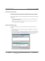
How to use the Call Classifier to customize inbound call handling . . . . . .26-2
How the Call Classifier works . . . . . . . . . . . . . . . . . . . . . . . . . . . . . . . . . . .26-3
Call Classifier requirements . . . . . . . . . . . . . . . . . . . . . . . . . . . . . . . . . . . . . . . 26-4
Viewing Call Classifier rules . . . . . . . . . . . . . . . . . . . . . . . . . . . . . . . . . . . . . . 26-4
Ordering rules in the Call Classifier dialog . . . . . . . . . . . . . . . . . . . . . . . . .26-5
Adding a Call Classifier rule to an auto attendant . . . . . . . . . . . . . . . . . . . . . . 26-6
Release 2.0
Wave Global Administrator Guide
September 2010
TOC-17
Prompting the caller to enter an identifying number . . . . . . . . . . . . . . . . . . . . 26-10
Using custom database queries in Call Classifier rules . . . . . . . . . . . . . . . . . .
Merging multiple SQL data fields into a single result field . . . . . . . . . . .
Setting up a stored procedure or query in your database . . . . . . . . . . . . .
Replacing many Call Classifier rules with a database query . . . . . . . . . .
26-13
26-20
26-20
26-22
Viewing Call Classifier information in the Call Monitor . . . . . . . . . . . . . . . . 26-23
PART 3
Key Wave Concepts
Chapter 27.
Understanding Wave Trunks
Trunk and channel terminology . . . . . . . . . . . . . . . . . . . . . . . . . . . . . . . . . . . . . 27-1
Analog and digital trunks . . . . . . . . . . . . . . . . . . . . . . . . . . . . . . . . . . . . . . . . . 27-3
Analog trunks . . . . . . . . . . . . . . . . . . . . . . . . . . . . . . . . . . . . . . . . . . . . . . . 27-3
Digital trunks . . . . . . . . . . . . . . . . . . . . . . . . . . . . . . . . . . . . . . . . . . . . . . . 27-3
Trunk groups . . . . . . . . . . . . . . . . . . . . . . . . . . . . . . . . . . . . . . . . . . . . . . . . . . . 27-4
Voice and data traffic . . . . . . . . . . . . . . . . . . . . . . . . . . . . . . . . . . . . . . . . . 27-5
Wave default trunk groups and connections . . . . . . . . . . . . . . . . . . . . . . . . 27-5
Trunk group hunt types . . . . . . . . . . . . . . . . . . . . . . . . . . . . . . . . . . . . . . . . . . . 27-7
Minimizing Glare . . . . . . . . . . . . . . . . . . . . . . . . . . . . . . . . . . . . . . . . . . . . 27-7
Hunt type examples . . . . . . . . . . . . . . . . . . . . . . . . . . . . . . . . . . . . . . . . . . 27-8
Chapter 28.
Understanding Wave IP Telephony
What is IP telephony? . . . . . . . . . . . . . . . . . . . . . . . . . . . . . . . . . . . . . . . . . . . . 28-2
IP call scenarios supported on the Wave system . . . . . . . . . . . . . . . . . . . . . . . . 28-3
Site-to-site IP calls . . . . . . . . . . . . . . . . . . . . . . . . . . . . . . . . . . . . . . . . . . . 28-3
IP phone calls . . . . . . . . . . . . . . . . . . . . . . . . . . . . . . . . . . . . . . . . . . . . . . . 28-3
DSP resources and licensing for IP telephony resources . . . . . . . . . . . . . . . . .
How many DSPs do you need? . . . . . . . . . . . . . . . . . . . . . . . . . . . . . . . . .
DSP resources required in a site-to-site scenario . . . . . . . . . . . . . . . . . . . .
DSP resources required in scenarios with IP phones . . . . . . . . . . . . . . . . .
Other DSP applications . . . . . . . . . . . . . . . . . . . . . . . . . . . . . . . . . . . . . . .
28-4
28-5
28-5
28-6
28-7
IP call routing . . . . . . . . . . . . . . . . . . . . . . . . . . . . . . . . . . . . . . . . . . . . . . . . . . 28-7
Release 2.0
Wave Global Administrator Guide
September 2010
TOC-18
Signaling Control Points . . . . . . . . . . . . . . . . . . . . . . . . . . . . . . . . . . . . . . .28-7
Direct site-to-site IP calls . . . . . . . . . . . . . . . . . . . . . . . . . . . . . . . . . . . . . .28-8
IP phones . . . . . . . . . . . . . . . . . . . . . . . . . . . . . . . . . . . . . . . . . . . . . . . . . . . . . 28-8
License requirements for IP phones . . . . . . . . . . . . . . . . . . . . . . . . . . . . . .28-9
MAC addresses . . . . . . . . . . . . . . . . . . . . . . . . . . . . . . . . . . . . . . . . . . . . . .28-9
IP addresses . . . . . . . . . . . . . . . . . . . . . . . . . . . . . . . . . . . . . . . . . . . . . . . . .28-9
Bandwidth management . . . . . . . . . . . . . . . . . . . . . . . . . . . . . . . . . . . . . . . . . 28-10
IP call quality management . . . . . . . . . . . . . . . . . . . . . . . . . . . . . . . . . . . . . . 28-11
Chapter 29.
Understanding Wave Call Routing
About call routing . . . . . . . . . . . . . . . . . . . . . . . . . . . . . . . . . . . . . . . . . . . . . . . 29-1
Internal call routing . . . . . . . . . . . . . . . . . . . . . . . . . . . . . . . . . . . . . . . . . . . . . 29-4
Outbound call routing . . . . . . . . . . . . . . . . . . . . . . . . . . . . . . . . . . . . . . . . . . . . 29-4
North American Numbering Plan . . . . . . . . . . . . . . . . . . . . . . . . . . . . . . . .29-5
Access profiles . . . . . . . . . . . . . . . . . . . . . . . . . . . . . . . . . . . . . . . . . . . . . . .29-6
Outbound routing tables . . . . . . . . . . . . . . . . . . . . . . . . . . . . . . . . . . . . . . .29-6
Automatic route selection . . . . . . . . . . . . . . . . . . . . . . . . . . . . . . . . . . . . . .29-8
Off-premise extensions . . . . . . . . . . . . . . . . . . . . . . . . . . . . . . . . . . . . . . .29-12
Destination access code/direct to trunk group . . . . . . . . . . . . . . . . . . . . . .29-13
Inbound call routing . . . . . . . . . . . . . . . . . . . . . . . . . . . . . . . . . . . . . . . . . . . . 29-15
Trunks receive no digits . . . . . . . . . . . . . . . . . . . . . . . . . . . . . . . . . . . . . .29-16
Wink start DID trunks . . . . . . . . . . . . . . . . . . . . . . . . . . . . . . . . . . . . . . . .29-17
ISDN trunks . . . . . . . . . . . . . . . . . . . . . . . . . . . . . . . . . . . . . . . . . . . . . . . .29-19
Trunks receive digits from another PBX . . . . . . . . . . . . . . . . . . . . . . . . . .29-20
Tandem call routing . . . . . . . . . . . . . . . . . . . . . . . . . . . . . . . . . . . . . . . . . . . . 29-21
Hunt groups . . . . . . . . . . . . . . . . . . . . . . . . . . . . . . . . . . . . . . . . . . . . . . . . . . 29-23
Hunt group hunt orders . . . . . . . . . . . . . . . . . . . . . . . . . . . . . . . . . . . . . . .29-24
Default hunt groups . . . . . . . . . . . . . . . . . . . . . . . . . . . . . . . . . . . . . . . . . .29-25
Outside lines . . . . . . . . . . . . . . . . . . . . . . . . . . . . . . . . . . . . . . . . . . . . . . . . . . 29-25
Single call variant . . . . . . . . . . . . . . . . . . . . . . . . . . . . . . . . . . . . . . . . . . .29-26
Multiple call variant . . . . . . . . . . . . . . . . . . . . . . . . . . . . . . . . . . . . . . . . .29-27
Automatic Line Selection . . . . . . . . . . . . . . . . . . . . . . . . . . . . . . . . . . . . . . . . 29-28
Automatic Line Selection on line appearance feature buttons . . . . . . . . .29-28
Release 2.0
Wave Global Administrator Guide
September 2010
TOC-19
Automatic Line Selection on Outside Line feature buttons . . . . . . . . . . . 29-30
Chapter 30.
Understanding Wave Data Networking
WAN technology . . . . . . . . . . . . . . . . . . . . . . . . . . . . . . . . . . . . . . . . . . . . 30-1
Network services . . . . . . . . . . . . . . . . . . . . . . . . . . . . . . . . . . . . . . . . . . . . 30-2
Microsoft’s Routing and Remote Access Service (RRAS) . . . . . . . . . . . . 30-2
The Wave LAN, segments, and subnets . . . . . . . . . . . . . . . . . . . . . . . . . . . . . . 30-2
Dial-up and persistent connections . . . . . . . . . . . . . . . . . . . . . . . . . . . . . . . . . .
Dial-up connections . . . . . . . . . . . . . . . . . . . . . . . . . . . . . . . . . . . . . . . . . .
Wave dial-in connection default settings . . . . . . . . . . . . . . . . . . . . . . . . . .
Persistent connection . . . . . . . . . . . . . . . . . . . . . . . . . . . . . . . . . . . . . . . . .
30-3
30-3
30-4
30-4
Wave data routing . . . . . . . . . . . . . . . . . . . . . . . . . . . . . . . . . . . . . . . . . . . . . . .
IP addressing . . . . . . . . . . . . . . . . . . . . . . . . . . . . . . . . . . . . . . . . . . . . . . .
Using a proxy server with Wave . . . . . . . . . . . . . . . . . . . . . . . . . . . . . . . .
Routing protocols . . . . . . . . . . . . . . . . . . . . . . . . . . . . . . . . . . . . . . . . . . . .
30-4
30-5
30-7
30-7
Packet filtering . . . . . . . . . . . . . . . . . . . . . . . . . . . . . . . . . . . . . . . . . . . . . . . . .
DMZ networks . . . . . . . . . . . . . . . . . . . . . . . . . . . . . . . . . . . . . . . . . . . . .
Private networks . . . . . . . . . . . . . . . . . . . . . . . . . . . . . . . . . . . . . . . . . . . .
Protocol and port filtering of common services . . . . . . . . . . . . . . . . . . . .
PPTP filtering . . . . . . . . . . . . . . . . . . . . . . . . . . . . . . . . . . . . . . . . . . . . . .
30-10
30-11
30-12
30-14
30-16
Network services . . . . . . . . . . . . . . . . . . . . . . . . . . . . . . . . . . . . . . . . . . . . . . .
Wave as DNS client . . . . . . . . . . . . . . . . . . . . . . . . . . . . . . . . . . . . . . . . .
Wave as WINS client . . . . . . . . . . . . . . . . . . . . . . . . . . . . . . . . . . . . . . . .
DHCP relays . . . . . . . . . . . . . . . . . . . . . . . . . . . . . . . . . . . . . . . . . . . . . . .
30-17
30-18
30-18
30-18
PART 4
Reference
Chapter 31.
Wave Reports
The Call Detail Report . . . . . . . . . . . . . . . . . . . . . . . . . . . . . . . . . . . . . . . . . . . . 31-2
Configuring the Call Detail Report . . . . . . . . . . . . . . . . . . . . . . . . . . . . . . 31-3
Call Detail Report specifications . . . . . . . . . . . . . . . . . . . . . . . . . . . . . . . . 31-4
The Trunk Statistics report . . . . . . . . . . . . . . . . . . . . . . . . . . . . . . . . . . . . . . . 31-14
Generating the Trunk Statistics report . . . . . . . . . . . . . . . . . . . . . . . . . . . 31-15
Release 2.0
Wave Global Administrator Guide
September 2010
TOC-20
Interpreting the Trunk Statistics report . . . . . . . . . . . . . . . . . . . . . . . . . . .31-17
About the Trunk Statistics Log . . . . . . . . . . . . . . . . . . . . . . . . . . . . . . . . .31-18
Downloading system reports . . . . . . . . . . . . . . . . . . . . . . . . . . . . . . . . . . . . . 31-23
Using the Report Generator . . . . . . . . . . . . . . . . . . . . . . . . . . . . . . . . . . . . . . 31-25
Creating digital phone labels . . . . . . . . . . . . . . . . . . . . . . . . . . . . . . . . . . . . . 31-27
Chapter 32.
SNMP Agents
SNMP agent and alarm configuration . . . . . . . . . . . . . . . . . . . . . . . . . . . . . . . 32-2
Vertical Communications SNMP agents . . . . . . . . . . . . . . . . . . . . . . . . . . . . . 32-2
.Environment SNMP agent . . . . . . . . . . . . . . . . . . . . . . . . . . . . . . . . . . . . . . . . 32-3
Fan Table . . . . . . . . . . . . . . . . . . . . . . . . . . . . . . . . . . . . . . . . . . . . . . . . . . .32-4
Power Supply Table . . . . . . . . . . . . . . . . . . . . . . . . . . . . . . . . . . . . . . . . . . .32-4
Fault Monitor Group . . . . . . . . . . . . . . . . . . . . . . . . . . . . . . . . . . . . . . . . . .32-5
Trap Info Group . . . . . . . . . . . . . . . . . . . . . . . . . . . . . . . . . . . . . . . . . . . . . .32-5
Traps . . . . . . . . . . . . . . . . . . . . . . . . . . . . . . . . . . . . . . . . . . . . . . . . . . . . . .32-6
Event Log agent . . . . . . . . . . . . . . . . . . . . . . . . . . . . . . . . . . . . . . . . . . . . . . . . 32-8
Event Log Trap Info Group . . . . . . . . . . . . . . . . . . . . . . . . . . . . . . . . . . . . .32-9
Event Log Traps . . . . . . . . . . . . . . . . . . . . . . . . . . . . . . . . . . . . . . . . . . . .32-10
Interfaces agent . . . . . . . . . . . . . . . . . . . . . . . . . . . . . . . . . . . . . . . . . . . . . . . . 32-12
Interfaces Group . . . . . . . . . . . . . . . . . . . . . . . . . . . . . . . . . . . . . . . . . . . .32-13
IP Telephony agent . . . . . . . . . . . . . . . . . . . . . . . . . . . . . . . . . . . . . . . . . . . . . 32-14
IP Telephony Trunk Summary Table . . . . . . . . . . . . . . . . . . . . . . . . . . . . .32-14
IP Telephony agent Traps . . . . . . . . . . . . . . . . . . . . . . . . . . . . . . . . . . . . .32-15
ISDN agent . . . . . . . . . . . . . . . . . . . . . . . . . . . . . . . . . . . . . . . . . . . . . . . . . . . 32-15
The Bearer Group . . . . . . . . . . . . . . . . . . . . . . . . . . . . . . . . . . . . . . . . . . .32-18
The Signaling Group . . . . . . . . . . . . . . . . . . . . . . . . . . . . . . . . . . . . . . . . .32-20
Repeater Private agent . . . . . . . . . . . . . . . . . . . . . . . . . . . . . . . . . . . . . . . . . . 32-22
Basic Package Group . . . . . . . . . . . . . . . . . . . . . . . . . . . . . . . . . . . . . . . . .32-23
Monitor Group . . . . . . . . . . . . . . . . . . . . . . . . . . . . . . . . . . . . . . . . . . . . . .32-27
Monitor Repeater 100 Table . . . . . . . . . . . . . . . . . . . . . . . . . . . . . . . . . . .32-34
Station Private SNMP agent . . . . . . . . . . . . . . . . . . . . . . . . . . . . . . . . . . . . . . 32-35
Common Group . . . . . . . . . . . . . . . . . . . . . . . . . . . . . . . . . . . . . . . . . . . . .32-35
Station Card Group . . . . . . . . . . . . . . . . . . . . . . . . . . . . . . . . . . . . . . . . . .32-36
Release 2.0
Wave Global Administrator Guide
September 2010
TOC-21
Digit Table Group . . . . . . . . . . . . . . . . . . . . . . . . . . . . . . . . . . . . . . . . . . . 32-40
External Voicemail System Group . . . . . . . . . . . . . . . . . . . . . . . . . . . . . . 32-42
Traps . . . . . . . . . . . . . . . . . . . . . . . . . . . . . . . . . . . . . . . . . . . . . . . . . . . . . 32-43
Chapter 33.
Self Test Daemon (STD) SNMP agent . . . . . . . . . . . . . . . . . . . . . . . . . . . . . .
System Group . . . . . . . . . . . . . . . . . . . . . . . . . . . . . . . . . . . . . . . . . . . . . .
Component Group . . . . . . . . . . . . . . . . . . . . . . . . . . . . . . . . . . . . . . . . . .
STD SNMP Agent Traps . . . . . . . . . . . . . . . . . . . . . . . . . . . . . . . . . . . . .
32-44
32-45
32-46
32-47
T-1 Private SNMP agent . . . . . . . . . . . . . . . . . . . . . . . . . . . . . . . . . . . . . . . . .
Card Table . . . . . . . . . . . . . . . . . . . . . . . . . . . . . . . . . . . . . . . . . . . . . . . .
Trunk Table . . . . . . . . . . . . . . . . . . . . . . . . . . . . . . . . . . . . . . . . . . . . . . .
Channel Table . . . . . . . . . . . . . . . . . . . . . . . . . . . . . . . . . . . . . . . . . . . . . .
T-1 Private Agent Traps . . . . . . . . . . . . . . . . . . . . . . . . . . . . . . . . . . . . . .
32-51
32-51
32-53
32-57
32-60
System Locale Settings
Setting and viewing system locale settings . . . . . . . . . . . . . . . . . . . . . . . . . . . . 33-1
Chapter 34.
Trunk Settings
Line Build Out settings . . . . . . . . . . . . . . . . . . . . . . . . . . . . . . . . . . . . . . . . . . . 34-1
Customizing transmit and receive signal settings . . . . . . . . . . . . . . . . . . . 34-2
Trunk timing values . . . . . . . . . . . . . . . . . . . . . . . . . . . . . . . . . . . . . . . . . . . . . . 34-5
T-1 trunk timing values . . . . . . . . . . . . . . . . . . . . . . . . . . . . . . . . . . . . . . . 34-5
Analog trunk timing values . . . . . . . . . . . . . . . . . . . . . . . . . . . . . . . . . . . . 34-9
Chapter 35.
Starting the TFTP Server
Starting the TFTP Server . . . . . . . . . . . . . . . . . . . . . . . . . . . . . . . . . . . . . . . . . . 35-1
PART 5
Appendices
Chapter A.
Protecting Your Phone System Against Toll Fraud
Typical toll fraud strategies . . . . . . . . . . . . . . . . . . . . . . . . . . . . . . . . . . . . . . . . A-1
Identifying toll fraud . . . . . . . . . . . . . . . . . . . . . . . . . . . . . . . . . . . . . . . . . . . . . A-2
Securing your system against toll fraud . . . . . . . . . . . . . . . . . . . . . . . . . . . . . . A-3
Password security . . . . . . . . . . . . . . . . . . . . . . . . . . . . . . . . . . . . . . . . . . . . . A-3
Release 2.0
Wave Global Administrator Guide
September 2010
TOC-22
Changing the Admin and Operator passwords . . . . . . . . . . . . . . . . . . . . . .
Identifying users with security-risk passwords . . . . . . . . . . . . . . . . . . . . . .
User permissions . . . . . . . . . . . . . . . . . . . . . . . . . . . . . . . . . . . . . . . . . . . . .
Setting up dialing restrictions . . . . . . . . . . . . . . . . . . . . . . . . . . . . . . . . . . .
Making account logon more secure . . . . . . . . . . . . . . . . . . . . . . . . . . . . . . .
Securing your phone system database . . . . . . . . . . . . . . . . . . . . . . . . . . . . .
Securing SIP stations . . . . . . . . . . . . . . . . . . . . . . . . . . . . . . . . . . . . . . . . . .
Checking for current scams . . . . . . . . . . . . . . . . . . . . . . . . . . . . . . . . . . . . .
A-3
A-4
A-5
A-5
A-6
A-7
A-7
A-7
Responding to toll fraud attempts . . . . . . . . . . . . . . . . . . . . . . . . . . . . . . . . . . . . A-8
Chapter B.
Wave Software License Agreement
End User Software License . . . . . . . . . . . . . . . . . . . . . . . . . . . . . . . . . . . . . . . . B-1
Chapter C.
Third-party Software License Agreements
XML parsing software . . . . . . . . . . . . . . . . . . . . . . . . . . . . . . . . . . . . . . . . . . . . C-1
PuTTY executables and source code . . . . . . . . . . . . . . . . . . . . . . . . . . . . . . . . . C-3
WinSCP . . . . . . . . . . . . . . . . . . . . . . . . . . . . . . . . . . . . . . . . . . . . . . . . . . . . . . . C-4
Wireshark . . . . . . . . . . . . . . . . . . . . . . . . . . . . . . . . . . . . . . . . . . . . . . . . . . . . . . C-4
TFTP Server . . . . . . . . . . . . . . . . . . . . . . . . . . . . . . . . . . . . . . . . . . . . . . . . . . . . C-4
Openfire . . . . . . . . . . . . . . . . . . . . . . . . . . . . . . . . . . . . . . . . . . . . . . . . . . . . . . . C-6
GNU General Public License . . . . . . . . . . . . . . . . . . . . . . . . . . . . . . . . . . . . . . . C-7
Chapter D.
Service Confirmation Letters and Provisioning Information Forms
Sample trunk provisioning information form . . . . . . . . . . . . . . . . . . . . . . . . . . . D-2
Sample trunk service confirmation letter . . . . . . . . . . . . . . . . . . . . . . . . . . . . . . D-3
Chapter E.
Wave Port Usage
Wave Global Administrator port usage . . . . . . . . . . . . . . . . . . . . . . . . . . . . . . . E-1
IP telephony port usage . . . . . . . . . . . . . . . . . . . . . . . . . . . . . . . . . . . . . . . . . . . E-2
Wave SIP port usage . . . . . . . . . . . . . . . . . . . . . . . . . . . . . . . . . . . . . . . . . . E-2
Aastra SIP port usage . . . . . . . . . . . . . . . . . . . . . . . . . . . . . . . . . . . . . . . . . E-3
WaveNet port usage . . . . . . . . . . . . . . . . . . . . . . . . . . . . . . . . . . . . . . . . . . . . . . E-3
Wave Add-on port usage . . . . . . . . . . . . . . . . . . . . . . . . . . . . . . . . . . . . . . . . . . E-4
Release 2.0
Wave Global Administrator Guide
September 2010
TOC-23
Wave Global Manager port usage . . . . . . . . . . . . . . . . . . . . . . . . . . . . . . . . E-4
Wave Global Reporter port usage . . . . . . . . . . . . . . . . . . . . . . . . . . . . . . . . E-5
Index
Release 2.0
Wave Global Administrator Guide
September 2010
TOC-24
Release 2.0
Wave Global Administrator Guide
September 2010
PART 1
Initial Configuration and Administration
Release 2.0
Wave Global Administrator Guide
September 2010
Release 2.0
September 2010
Chapter 1
1.
About This Guide
CHAPTER CONTENTS
About Wave ISM . . . . . . . . . . . . . . . . . . . . . . . . . . . . . . . . . . . . . . . . . . . . . . . . 1-1
Getting the most out of this guide . . . . . . . . . . . . . . . . . . . . . . . . . . . . . . . . . . . 1-1
Where to start. . . . . . . . . . . . . . . . . . . . . . . . . . . . . . . . . . . . . . . . . . . . . . . . . . . 1-2
Using the Help system . . . . . . . . . . . . . . . . . . . . . . . . . . . . . . . . . . . . . . . . . . . . 1-3
Conventions used in this guide . . . . . . . . . . . . . . . . . . . . . . . . . . . . . . . . . . . . . 1-3
Related reading . . . . . . . . . . . . . . . . . . . . . . . . . . . . . . . . . . . . . . . . . . . . . . . . . 1-5
Support services . . . . . . . . . . . . . . . . . . . . . . . . . . . . . . . . . . . . . . . . . . . . . . . . 1-6
Web site . . . . . . . . . . . . . . . . . . . . . . . . . . . . . . . . . . . . . . . . . . . . . . . . . . . . . . . 1-6
System security . . . . . . . . . . . . . . . . . . . . . . . . . . . . . . . . . . . . . . . . . . . . . . . . . 1-6
About Wave ISM
Welcome to Wave ISM, a unified platform designed for scalability, reliability, and ease of use
that delivers comprehensive communication support, including PBX voice capability,
multiprotocol router capabilities, full LAN/WAN connectivity, and a suite of communication
applications.
Getting the most out of this guide
This guide provides detailed information about configuring the Vertical Wave Server and
Vertical Wave system software.
This guide is intended for network administrators, phone system administrators, and office
personnel who are responsible for configuring and maintaining the Wave system.
Release 2.0
Wave Global Administrator Guide
September 2010
1-2
Chapter 1: About This Guide
Where to start
This guide provides information about all parts of the remote administration interface used to
perform the configuration and system administration steps to set up the Wave system. An
extensive online Help system provides detailed information about additional functionality not
described in this guide.
Note how the following terms are used in this guide:
•
“Wave ISM” refers to the Wave software infrastructure, Wave Integrated Services
Manager.
•
“Wave Server” refers to the physical server PC on which Wave ISM runs. Most of the
information in this guide applies to all Wave Server models. When information applies to
a specific to a Wave Server model, the model is identified, for example “Wave IP 2500”
or “Wave IP 500”. For more about the different Wave Server models, see the Wave Server
Installation Guide.
•
“Wave” refers to your Wave phone system as a whole.
Where to start
This guide includes information for readers at a variety of levels. To get the most out of the
documentation, start by reading the parts that are most relevant to your level of experience.
For new Wave system administrators
1 Begin by reading PART 3, “Key Wave Concepts”
2 Next, work through the procedures in PART 1, “Initial Configuration and Administration”
to configure the basic Wave system settings.
3 Then choose the advanced features you wish to configure from PART 2, “Advanced
Configuration and Administration”.
4 Refer to PART 4, “Reference”, as necessary.
That’s all you need to begin configuring most typical Wave system installations.
Release 2.0
Wave Global Administrator Guide
September 2010
1-3
Chapter 1: About This Guide
Using the Help system
For experienced Wave system administrators
1 Begin by working through the procedures in PART 1, “Initial Configuration and
Administration”, to configure the basic Wave ISM system settings.
2 Then choose the advanced features you wish to configure from PART 2, “Advanced
Configuration and Administration”.
3 Refer to PART 3, “Key Wave Concepts”, and PART 4, “Reference”, as necessary.
Using the Help system
The Wave Help system provides context-sensitive Help. To access Help, use the following
methods:
•
From the Wave Global Administrator Management Console, click the Help icon located
at the top right corner, then select a topic from either the Contents tab or the Index tab.
Use the Search tab to locate topics that include specific text.
•
From each Management Console applet, click the Help button to directly access the
relevant Help topic.
Conventions used in this guide
In the course of describing Wave system features and functions, this guide uses the conventions
described in this section.
Special messages
Note: A note highlights information that is important or of special interest.
Hint: A hint relays information to help you perform a task.
Caution: A caution highlights information that helps you prevent damage to the
equipment or to data. It tells you how to avoid the problem.
Warning: A warning alerts you to a situation that could cause you physical harm.
Release 2.0
Wave Global Administrator Guide
September 2010
1-4
Chapter 1: About This Guide
Conventions used in this guide
Type conventions
Type Convention
Used to Indicate
Bold
User interface elements (buttons, field labels, and tab labels)
Italics
Book titles, glossary words, and word emphasis
Courier font
Screen text and user-typed command line entries
Initial Caps
Product names, menu titles, window titles, application titles,
dialog titles, hypertext links, file names, and directories
Terms used
Term
How to Interact
Click
Click the left mouse button.
Right-click
Click the right mouse button.
Shift-click
Hold the Shift key while clicking the left mouse button.
Ctrl-click
Hold the Ctrl key while clicking the left mouse button.
Ctrl+Q
Hold the Ctrl key while pressing one or more additional keys.
Enter
Press the Enter key or select OK.
Type
Type the indicated text, but do not press the Enter key or select
OK.
Press
Press only the key or keys referred to.
Check
Place a check mark in the check box.
Select
Choose an option from a menu, drop-down list, or list of radio
buttons.
Release 2.0
Wave Global Administrator Guide
September 2010
1-5
Chapter 1: About This Guide
Related reading
Related reading
For information about this version of Wave ISM, including new features, known issues, and
other late-breaking information, see the Release Notes included on the Documentation CD.
The following additional documents are included with the Wave Server in Acrobat format, and
can be found on the Documentation CD.
Manuals
Wave Server Installation Guide. Provides detailed instructions for physically installing the
Wave Server and Wave ISM and performing initial system configuration.
Wave ISM System Recovery Guide. Describes how to use the Wave ISM System Recovery Disk
to restore your Wave Server to its original factory settings for emergency recovery.
Wave ViewPoint User Guide. Provides task-based instructions on how to use ViewPoint,
including call control, working from remote locations, participating as an agent in a Contact
Center, and so forth.
Wave Phone User Guide. Describes how to use SIP phones, digital phones, analog phones, and
SIUP softphones with Wave.
Wave Server Hardware Reference Guide. Provides detailed technical information about the
Wave Server hardware components.
Wave Contact Center Administrator Guide. Describes how to use the separately-licensed Wave
Contact Center to provide full-featured call distribution.
Quick Reference Guides
Wave Analog Phone Quick Reference Guide. Provides instructions for using analog phones
with Wave.
Wave Digital Phone Quick Reference Guide. Provides instructions for digital phones with
Wave.
Release 2.0
Wave Global Administrator Guide
September 2010
1-6
Chapter 1: About This Guide
Support services
Wave SIP Phone Quick Reference Guide. Provides instructions for using SIP phones with
Wave.
Wave Voice Mail Quick Reference Guide. Provides instructions for using Wave ISM Voice
Mail features.
Support services
Vertical Communications has worked diligently to produce the highest quality communications
system possible. In the course of installing or customizing a system customers may require
personal attention.
For technical support contact your Vertical Wave provider.
Web site
For more information about Vertical Communications, Inc. and the Vertical Wave product line,
contact your Vertical Wave provider. To do so, call 1-877-VERTICAL, or visit the Vertical
corporate Web site:
http://www.vertical.com
System security
You are responsible for the security of your Wave system. Unauthorized use of the Wave system
could result in toll fraud. Your system administrator must read all system administration
documentation to understand which configuration options can introduce the risk of toll fraud
and which configuration options can be activated or deactivated to prevent it.
For more information, see A, “Protecting Your Phone System Against Toll Fraud.”
Note: Vertical Communications, Inc. does not warrant that the configuration software is
immune from or will prevent unauthorized use of common-carrier telecommunications facilities
and services accessed through or connected to the Wave Server. Vertical Communications, Inc.
is not responsible for any charges resulting from unauthorized use.
Release 2.0
Wave Global Administrator Guide
September 2010
Chapter 2
2.
Navigating the Management Console
CHAPTER CONTENTS
Before logging on . . . . . . . . . . . . . . . . . . . . . . . . . . . . . . . . . . . . . . . . . . . . . . . . 2-1
Management Console basics . . . . . . . . . . . . . . . . . . . . . . . . . . . . . . . . . . . . . . . 2-5
Starting and exiting applets . . . . . . . . . . . . . . . . . . . . . . . . . . . . . . . . . . . . . . . . 2-5
Navigating applet tree structures . . . . . . . . . . . . . . . . . . . . . . . . . . . . . . . . . . . 2-10
Using the User/Group Management applet . . . . . . . . . . . . . . . . . . . . . . . . . . . 2-13
This chapter provides general navigation information, as well as descriptions of applets and
dialogs that you may use frequently to configure various Vertical Wave settings.
Before logging on
Windows XP SP2 users only: If you are logging on to the Management Console from an
administrator PC running Microsoft Windows XP SP2, be sure to add the Wave Server to the
list of trusted sites in your browser. (This step was performed during system installation if a
Windows XP SP2 administrator PC was used to connect to the Wave Server, as described in
Chapter 4 in the Wave Server Installation Guide.)
If you are now using a different Windows XP SP2 administrator PC to connect to the
Wave Server, see “Troubleshooting Management Console problems” in Appendix G in the
Wave Server Installation Guide for important required steps to prevent problems while running
Management Console applets.
Release 2.0
Wave Global Administrator Guide
September 2010
2-2
Chapter 2: Navigating the Management Console
Before logging on
Logging on for the first time
During installation, you connected an administrator PC to the Wave Server using a modem or
an Ethernet port on the Integrated Services Card. If you have not yet made an initial connection,
see Chapter 4 in the Wave Server Installation Guide for instructions.
The first time you log on to the Management Console, you use a default user name and
password. You will change the default name and password later.
To log on for the first time
1 On the client workstation, launch Microsoft Internet Explorer.
2 Enter the default host name or IP address on the address line of your browser.
The default host name is io-default. The default IP address is 192.168.205.1.
Note: When you launch the Management Console, a dialog may appear asking you to install
a specific version of the Java 2 runtime environment. Click Yes in this dialog to perform the
installation.
The Wave Global Administrator Log On dialog opens.
Release 2.0
Wave Global Administrator Guide
September 2010
2-3
Chapter 2: Navigating the Management Console
Before logging on
3 Enter your user name and password. The initial default logon values are:
User Name. GlobalAdministrator
Password. Vertical4VoIP!
Note: Password is case-sensitive.
You will see the following warning each time you log on using the default password:
4 Click Log On. If other users are logged on to the Management Console, a list of logged on
users will appear. Click OK to close the dialog.
Release 2.0
Wave Global Administrator Guide
September 2010
Before logging on
2-4
Chapter 2: Navigating the Management Console
If your logon is successful, the Management Console opens.
Release 2.0
Wave Global Administrator Guide
September 2010
2-5
Chapter 2: Navigating the Management Console
Management Console basics
Management Console basics
The Wave Global Administrator Management Console is a portal to the applets and their
associated dialogs that are used to configure and manage Wave ISM.
More information is available about how to use an applet:
•
Administration tab applets. See this manual, or click Help in an applet dialog.
•
Applications tab applets. See the documentation for that application.
•
Diagnostics tab applet. Click Help in an applet dialog.
This section describes:
•
Starting and exiting applets. See page 2-5.
•
Navigating applet tree structures. See page 2-10.
Note: If you are accessing the Management Console from an administrator PC running
Microsoft Windows XP SP2 and you experience problems, for example applets appear to be
disabled or hidden, see “Troubleshooting Management Console problems” in Appendix G in the
Wave Server Installation Guide.
Starting and exiting applets
To start any applet, click its icon in the Management Console. Exiting an applet is slightly
different depending on the applet type. See the following sections for details.
Dialog applets vs. remote access applets
There are two types of applets accessible from the Management Console, dialog applets and
remote access applets.
Release 2.0
Wave Global Administrator Guide
September 2010
2-6
Chapter 2: Navigating the Management Console
Starting and exiting applets
Dialog applets
Most applets are dialog applets. Dialog applets directly open a master dialog, for example the
First Digit Table applet:
Some applets consist of a single master dialog, while others may link to sub-dialogs.
Exiting a dialog applet
Click Done or OK to close each sub-dialog until you return to the master dialog.
From most master dialogs, you can click any of the following:
•
Done. Exits the dialog, prompting you to save any changes that you made.
•
Restore. Returns the fields in the dialog to the previous (unmodified) values.
•
Apply. Saves your changes without closing the dialog.
•
Help. Opens a Help topic that describes how to configure the settings in the master dialog
and any associated sub-dialogs.
Release 2.0
Wave Global Administrator Guide
September 2010
2-7
Chapter 2: Navigating the Management Console
Starting and exiting applets
Remote access applets
Some Management Console applets (listed in the next table) open a Remote Desktop
Connection to the associated application, for example the Date and Time applet:
The following table lists the Management Console applets that are launched through remote
access:
Release 2.0
Tab
Applet
For more information, see...
Administration
RAID 1 Configuration
“Using Disk Management and configuring
RAID 1” on page 23-38
Date and Time
“Setting the system date and time” in Chapter 6
in the Wave Server Installation Guide
Wave Global Administrator Guide
September 2010
2-8
Chapter 2: Navigating the Management Console
Starting and exiting applets
Tab
Applet
For more information, see...
User/Group
Management
“Using the User/Group Management
applet” on page 2-13
Local TAPI
Configuration
Diagnostics
Microsoft RRAS
Chapter 21
Network Connections
Chapter 21
System Information
Microsoft System Information Help
Performance Monitor
Microsoft Management Console Performance
Help
Task Manager
Microsoft Windows Task Manager Help
Event Viewer
Viewing the Wave Event Log
Network Monitor
Microsoft Network Monitor Help
Starting a remote access applet
When you start a remote access applet from the Management Console, Wave ISM attempts to
start a Remote Desktop Connection:
Release 2.0
Wave Global Administrator Guide
September 2010
2-9
Chapter 2: Navigating the Management Console
Starting and exiting applets
Click Yes to continue. For the User/Group Management applet only, you are presented with the
Vertical Wave Global Administrator Log On dialog, with your logon credentials already filled
in. Click OK to continue. See “Using the User/Group Management applet” on page 2-13 for
more information.
Exiting a remote access applet
When you are done using the application, choose Exit from your browser’s File menu, or click
the X at the upper right of the application window to return to the Management Console.
Click
Note: You can click the System Desktop icon at the top of the Management Console in order to
access other resources on the Wave ISM (as opposed to running a specific applet.) To then return
to the Management Console, you must log off from the Windows Desktop. To do so, choose
Start > Logoff.
If you are having trouble establishing the Remote Desktop Connection...
If you have trouble establishing a Remote Desktop Connection, check your browser proxy
settings.
To check the proxy settings
1 From the Tools menu of Internet Explorer, choose Internet Options.
2 Click the Security tab.
3 If necessary, click the Local intranet icon to select it.
4 Click the Sites button.
5 If necessary, select the Include all sites that bypass the proxy server option.
6 Click the Advanced button.
7 Enter the specific Wave host name in the Add this Web site to the zone field.
8 Click Add.
9 Click OK to save your changes until all dialogs are closed.
Release 2.0
Wave Global Administrator Guide
September 2010
2-10
Chapter 2: Navigating the Management Console
Navigating applet tree structures
Left-handed mouse users
Once a Remote Desktop Connection is established, a user with a left-handed mouse may notice
that the mouse buttons suddenly appear to become unresponsive. In actuality, the mouse buttons
have been reassigned to right-handed settings, and the buttons are now reversed. This happens
because when you connect to a PC via a Remote Desktop Connection, mouse and keyboard
settings are inherited from the PC to which you connect.
Navigating applet tree structures
Several of the Management Console applets employ tree structures to represent the items you
are configuring. For example, the Trunk Configuration applet uses a tree structure to represent
cards or modules and the trunks and channels you are configuring.
Navigating applet tree structures typically includes the following:
Release 2.0
•
Displaying and hiding items in a tree (for example, the channels of a card or module in
the Trunk Configuration applet)
•
Selecting items in a tree
Wave Global Administrator Guide
September 2010
2-11
Chapter 2: Navigating the Management Console
Navigating applet tree structures
Displaying and hiding items in a tree
To display items in a tree
1 Open the appropriate applet, if it is not already open.
Note: A green dot next to a trunk, channel, port, or card, or module indicates that it is in
service. A red X indicates that the item is not in service.
2 Click the plus (+) sign next to the appropriate module or card to display the items within it.
Release 2.0
Wave Global Administrator Guide
September 2010
Navigating applet tree structures
2-12
Chapter 2: Navigating the Management Console
To hide items in a tree
1 Complete any configuration changes you are making in dialogs opened from an applet, and
return to that applet. The Station Ports applet is shown in the following example.
2 Click the minus (-) sign next to the appropriate trunk, module, or card to hide the items
within it.
Release 2.0
Wave Global Administrator Guide
September 2010
2-13
Chapter 2: Navigating the Management Console
Using the User/Group Management applet
Selecting items in a tree
To select items in a tree
1 Open the appropriate applet, if it is not already open, and display the items within a trunk,
card, or module.
2 Select the items you want to configure.
•
To select a contiguous range of items, select the first item in the range, then hold
down the Shift key while you select the last item in the range.
•
To select a noncontiguous range of items, hold down the Ctrl key while you select
each item.
When you access dialogs containing values that apply to the selected channels, what you
see depends on which channels are selected:
•
If all channels selected have the same values, those values are displayed
•
If all channels selected have the same values, and those values are the default values,
the word Default is displayed
•
If the channels selected have different values, the expression No Common Value is
displayed. In the case of check boxes with different values, the check boxes are
deselected and (No Common Value) is appended to their labels
Using the User/Group Management applet
The User/Group Management applet is a remote access applet that lets you configure users as
well as access many other Wave configuration and monitoring tools.
Release 2.0
Wave Global Administrator Guide
September 2010
Using the User/Group Management applet
2-14
Chapter 2: Navigating the Management Console
Accessing the User/Group Management applet
To access the User/Group Management applet
Click
1 From the Wave Global Administrator Management Console, click the User/Group
Management icon, located in the PBX Administration section.
2 A remote access session opens, connecting you to the Vertical Wave Global Administrator
Log On dialog, with your Wave ISM logon credentials already entered.
If your name and password do not appear, enter them.
Note: A username called “Admin” exists by default, with a password of 100. To create other
administrators, you must add users and give them Global Administrator permissions (see
“The Security \ Permissions tab” on page 11-84).
3 Do one of the following:
•
Enter your phone’s Station ID. To do so, press *00 on your telephone to retrieve your
station ID, and then enter that number. You must enter your station ID if you will need
to record an auto attendant prompt or user voice title using the audio controls. (See
“Using the audio controls” on page 2-20.)
•
Leave Station ID set to 0 if you do not need to use the audio controls. The audio
controls will be disabled in the various User/Group Management applet views.
4 Click OK. The User/Group Management applet opens.
Note: Leaving the Admin user password as 100 is a security risk that can cost your company
money due to toll fraud. For more information about system security, see Appendix A.
Release 2.0
Wave Global Administrator Guide
September 2010
2-15
Chapter 2: Navigating the Management Console
Using the User/Group Management applet
The User/Group Management applet interface
The User/Group Management applet interface is composed of views (see “Working in views”
on page 2-17). Each view enables you to configure, manage, or monitor an aspect of the Wave
system.
View
Description
See
Users
Manage Wave users. Includes
changing passwords and allocating
disk space to users for voicemail
messages and greetings.
“The Users view” on page 11-4
Groups
Manage ViewPoint Groups (groups of “The ViewPoint Groups view”
related extensions or contacts).
on page 12-3
Pickup
Groups
Manage Pickup Groups (groups of
extensions that can be answered by
all the users in the group).
“Configuring call pickup
groups” on page 16-5
Dialing
Services
View external first digits and
configure how they appear in
ViewPoint
“Configuring how first digit
extensions appear in
ViewPoint” on page 9-3
Auto
Attendants
Manage auto attendants that handle
and route inbound calls with voice
menus.
“Creating a new auto
attendant” on page 13-3
Queues
Manage groups of agents in Wave
Contact Center queues.
Wave Contact Center
Administrator Guide
Maintenance View a log recording Global
Log
Administrator actions.
Release 2.0
“Using the Maintenance Log
view” on page 22-3
Wave Global Administrator Guide
September 2010
2-16
Chapter 2: Navigating the Management Console
Using the User/Group Management applet
View
Description
See
Dial Plan
View and edit a complete list of
internally dialable numbers.
“Managing your dial plan with
the Dial Plan view” on page
22-2
System
Prompts
Listen to and change recordings used “The System Prompts view” on
for standard system prompts and
page 18-2
auto attendants.
Call Log
View a record of all the calls made on “Using the Call Log view” on
the system.
page 22-4
IVR Plug-Ins Manage Wave IVR Plug-ins, which
are custom interactive voice
response applications that you or
third parties can create.
Using the Tools menu
The Tools menu of the User/Group Management applet offers additional Wave features not
available from the views:
Release 2.0
Command
Description
See
Update Access
Codes
Change the access code used
for a particular dialing service.
“Changing an access code
in a user’s saved numbers”
(page 9-39)
Columns
Customize the columns that
appear in each view.
“Customizing columns”
(page 2-19)
Options
Customize the appearance of
names, Call Log size, and
defaults for station and extension
numbers.
“Assigning an extension”
on page 11-13
“Displaying a specific
number of Call Log
entries” (page 22-10)
Wave Global Administrator Guide
September 2010
2-17
Chapter 2: Navigating the Management Console
Using the User/Group Management applet
Command
Description
See
System Settings
Configure and customize several
aspects of your Wave system.
Chapter 4
Working in views
To open a view, click its button in the view bar on the left side of the User/Group Management
applet window.
You can also open a view by clicking the View menu and choosing a view.
Note: If a view is not available to you, you might not have permission to view it. Check with
your system administrator, or see “The Security \ Permissions tab” on page 11-84.
The main part of a view contains rows of the items that pertain to that view. For example, in the
Users view, each Wave user is displayed as an item on a row. Double-click an item to edit it.
Release 2.0
Wave Global Administrator Guide
September 2010
2-18
Chapter 2: Navigating the Management Console
Using the User/Group Management applet
Using commands in a view
A command always affects the item or items that are selected. To select multiple items, hold
down the CRTL key as you click the items. You can perform a command using any of the
following methods:
•
Choose a command from the view’s menu. For example, in the Users view, click the
Users menu and choose a command.
•
Click a toolbar button (see the next table).
•
Right-click an item and choose a command from the shortcut menu that opens. This is
often the fastest way to perform an command.
Using the User/Group Management applet toolbar
The User/Group Management applet toolbar is located on the main menu bar in each view. It
gives you quick access to several User/Group Management applet commands that are also
available through the User/Group Management applet menus.
To create a new item when you are working in any Wave view, click the arrow next to the first
button on the toolbar and select an item.
Release 2.0
Wave Global Administrator Guide
September 2010
2-19
Chapter 2: Navigating the Management Console
Using the User/Group Management applet
Customizing columns
Click a column header to sort by that column. Click again to sort in the reverse order. The arrow
in the column header shows by which column and in what direction the display is currently
sorted.
You can resize column widths by dragging the sides of the column headers.
For each view in the User/Group Management applet, you can choose the columns that you
want to see and the columns that you want to hide. Some views do not show all the available
columns by default.
To show or hide columns in a view
1 Choose Tools > Columns, or right-click a column header.The Columns dialog opens.
2 From the View drop-down list, choose the view you want to change.
3 Check a column to show it. Uncheck a column to hide it. For an explanation of the various
columns, click Help.
4 Click OK.
Working with voice files
A voice file is an audio recording that is stored as a file. Wave stores system prompts, greetings,
voice messages, and recorded conversations in voice files that you can play over your computer
speakers or on the phone. You can record voice files using the phone.
Wave voice files are in WAV format, but you can import files of other formats.
Note: When archiving voice messages or call recordings you can specify MP3 as the file
format. See “Archiving call recordings and voicemail” on page 22-31.
Release 2.0
Wave Global Administrator Guide
September 2010
Using the User/Group Management applet
2-20
Chapter 2: Navigating the Management Console
Using the audio controls
Wave’s audio controls make it easy to create and modify recordings of all types. The following
controls appear in Wave wherever you can create and listen to recordings.
To create and play recordings, use the buttons on the audio controls as shown in the following
table and speak into your phone.
Record
When you are ready to record, pick up your phone, and then
click this button. A beep signals that recording has begun.
Play
Click to listen to the recording.
Stop
When you are done recording, you can either hang up or click
this button.
Fast
Forward
Click to skip ahead while listening to the recording.
Rewind
Click to skip back while listening to the recording.
To move forward and backward within the recording, drag the slider bar.
Release 2.0
Wave Global Administrator Guide
September 2010
2-21
Chapter 2: Navigating the Management Console
Using the User/Group Management applet
Importing and exporting voice files
To import or export a voice file, use the import or export buttons on the recording control, as
shown in the following table.
Import
You can import a voice file in WAV format to use for any
Wave recording (greetings, voice titles, and so on).
Wave can import WAV files with a frequency of 8Khz, 11.025
Khz, 22.05 Khz, or 44.1 Khz.
Export
Release 2.0
You can export any of your recordings, including system
prompts and voice titles, to a WAV file or an MP3 file.
Wave Global Administrator Guide
September 2010
Release 2.0
September 2010
Chapter 3
3.
Before You Begin
CHAPTER CONTENTS
Before you begin . . . . . . . . . . . . . . . . . . . . . . . . . . . . . . . . . . . . . . . . . . . . . . . . 3-1
About the General Settings applet . . . . . . . . . . . . . . . . . . . . . . . . . . . . . . . . . . . 3-2
Entering basic system information . . . . . . . . . . . . . . . . . . . . . . . . . . . . . . . . . . . 3-4
Verifying installed components. . . . . . . . . . . . . . . . . . . . . . . . . . . . . . . . . . . . . . 3-6
Adding accounts and passwords . . . . . . . . . . . . . . . . . . . . . . . . . . . . . . . . . . . . 3-8
Setting the message-waiting dial tone duration . . . . . . . . . . . . . . . . . . . . . . . . 3-10
Suppressing ringing on any digital phone that is receiving a page . . . . . . . . . 3-11
Configuring the time service. . . . . . . . . . . . . . . . . . . . . . . . . . . . . . . . . . . . . . . 3-11
Before you begin
Before you configure your Wave system, make sure the following installations and records are
complete:
•
Cabling and hardware installations
•
Trunk (or service) confirmation letter from your phone service provider
•
Your Configuration and Design Worksheets (from your Vertical Communications
reseller) on trunking, extensions, incoming and outgoing call flow, voice mail access, and
your dialing plan
To manage your Wave system, you need a client workstation with the following minimum
configuration:
Release 2.0
•
A PC running Microsoft Windows 2000, Windows XP, or Windows Server 2003 and at
least 256MB of RAM
•
LAN or WAN connectivity through an Ethernet card or modem
•
Microsoft Internet Explorer 6.0 Service Pack 1
Wave Global Administrator Guide
September 2010
3-2
Chapter 3: Before You Begin
About the General Settings applet
Note: Some of the Management Console applets display dialogs, warnings, and panels
automatically. If you have installed a browser pop-up blocker on your client PC, these pop-ups
may not appear. You can usually configure blocker software to allow pop-ups from specific
domains or IP addresses.
About the General Settings applet
You use the General Settings applet to set many system-wide settings for your Wave system.
The following list provides links to information about the tasks you can accomplish via the
various tabs in the General Settings applet.
System tab
•
Company Name, Main Number, Serial Number, Voice Mail System. See “Entering basic
system information” on page 3-4.
Note: During system installation, you will already have used the General Settings
applet to enter some basic system information, as described in Chapter 6 in the Wave
Server Installation Guide.
•
•
Locale. See “Setting and viewing system locale settings” on page 33-1.
Notify when less than ___ megabytes free. See “Setting the minimum free hard drive
space notification limit” on page 23-24.
•
Enable IMpulse Instant Message Service. See “Enabling the Instant Messaging server”
on page 16-42.
PBX tab
•
•
Enable Public Address. See “Enabling Public Address” on page 16-24.
Allow Automatic Phone Relocation. See “Enabling automatic phone relocation” on page
16-25.
Release 2.0
•
Enable DSS/BLF updates when the user’s phone is active on any line. See “Enabling
DSS/BLF updates when the user’s phone is active on any line” on page 16-27.
•
Music On Hold. See “Configuring Music On Hold” on page 16-16.
•
External Caller ID. See “Configuring system-wide Caller ID settings” on page 16-11.
•
Night Answer Service. See “Configuring Night Answer” on page 16-29.
•
Fax Redirect Service. See “Configuring Fax Redirect” on page 16-15.
Wave Global Administrator Guide
September 2010
3-3
Chapter 3: Before You Begin
About the General Settings applet
PBX (Advanced) tab
•
Use Forwarding Target of Last Destination in Chain. See “Configuring calls to be
forwarded to the RNA forwarding target” on page 13-26.
•
•
Suppress ring if receiving page. See “Suppressing ringing on any digital phone that is
receiving a page” on page 3-11.
Stutter Dial Tone Duration (Seconds). See “Setting the message-waiting dial tone
duration” on page 3-10.
•
Call Park. See “Configuring Call Park options” on page 16-4.
•
Trunking. See “Configuring external call routing restrictions” on page 16-14”.
•
When dialing, wait up to ___ seconds for next digit to be entered. See “Configuring
dialing time-out” on page 16-13.
•
Require external access code to dial emergency numbers. See “Requiring an access
code for emergency number dialing” on page 16-13.
•
Enable Call Return ___ Trunk Access Code (TAC). See “Enabling call return for external
calls” on page 16-28.
WaveMail tab
•
See “Synchronizing a user’s Wave voice messages and contacts with the user’s e-mail
program” on page 11-26.
ISDN tab
•
Outbound Caller ID, Inbound Caller ID. See “Configuring system-wide ISDN settings” on
page 17-12.
Fault Monitor tab
•
View Fault Monitor Error Logs. See “Viewing the Fault Monitor Error Logs” on page
23-19.
Time Service tab
•
Release 2.0
See “Configuring the time service” on page 3-11.
Wave Global Administrator Guide
September 2010
3-4
Chapter 3: Before You Begin
Entering basic system information
Entering basic system information
Note the following about the information you enter according to the following instructions:
•
Company Name and Main Number are both used in your external Caller ID.
•
The Wave Server Serial Number is used by Global Manager to identify each Wave Server
uniquely. Also, your Vertical Technical Support representative may request it while
troubleshooting a problem.
•
The Locale that you specify enables appropriate locale-specific system settings including
ring cadence, minimum analog hook flash, tone set, line impedance, trunk locale, and so
forth. For more about changing the Locale setting, see Chapter 33.
•
Voice Mail System specifies the extension that users dial, or trunks group use, to reach the
voice mail hunt group. The default VoiceMail extension is 550. If you want to use a
different extension to access voicemail, see “Configuring the VoiceMail extension” on
page 7-7.
To enter the basic system information
1 If necessary, click the Administration tab of the Management Console.
Click
2 Click the General Settings icon, located in the General Administration section.
3 Click the System tab.
4 Enter your Company Name.
5 Enter your company’s Main Number, for example 6173540600. You cannot enter
parentheses, spaces or dashes.
Release 2.0
Wave Global Administrator Guide
September 2010
3-5
Chapter 3: Before You Begin
Entering basic system information
6 Enter the entire Serial Number of the Wave Server. The serial number is located on the side
of the chassis, and is in the following format, where AA is an alphabetical value and n is a
numerical value:
AAnnnnnnnnnn
7 If the Locale setting is correct for your system, go to step 8. If not, select your locale from
the drop-down list.
When you change the Locale setting, you are reminded that you may need to update any
area codes that you have already defined in the First Digit Table to reflect new area code
requirements for the selected locale.
For more about editing the First Digit Table, see “Setting the home area code” on page 7-5.
Caution: The Customize button allows you to customize the advanced settings for
the locale specified. The default advanced settings for a locale should work for you
unless you have a unique environment. These are expert settings that should not
be modified unless you are instructed to do so by your Vertical Technical Support
representative. For more about the advanced settings for a locale, see Chapter 33.
Click OK to continue.
8 Select the Voice Mail System extension used to reach the voice mail hunt group. The
default is 550 (which is adequate for most systems) but you can map it to a different pilot
number (see “Configuring the VoiceMail extension” on page 7-7.)
9 Click Apply to save your changes.
10 Click Done to return to the Management Console.
Release 2.0
Wave Global Administrator Guide
September 2010
3-6
Chapter 3: Before You Begin
Verifying installed components
Verifying installed components
You can verify that all of your installed cards and modules are recognized by the Wave system
and functioning properly by using the Chassis View applet. Chassis View shows all cards and
modules installed in the Wave chassis; LEDs display status dynamically.
To verify installed components
1 If necessary, click the Administration tab of the Management Console.
Click
2 Click the Chassis View icon, located in the General Administration section.
3 Make sure all the cards and modules you have installed are visible in the graphical
representation of your Wave chassis. The Chassis View looks different depending on your
Wave Server model.
On the Wave IP 500 Server, the Chassis View looks like this:
Release 2.0
Wave Global Administrator Guide
September 2010
3-7
Chapter 3: Before You Begin
Verifying installed components
On the Wave IP 2500 Server, the Chassis View looks like this:
Position the cursor on a card or module to display an expanded version of it, along with
statistics for that card or module, to the right of the representation of the entire chassis.
Clicking a card or module takes you to the appropriate configuration applet.
4 If a card or module is not visible in Chassis View, check the physical LEDs to make sure
they are green (on and operational).
If the physical LEDs are red (nonoperational):
a
Shut down and then power off the Wave system.
b
Reseat the card or module.
c
Restart the system, reopen your browser window, and check Chassis View again.
d
Verify that the components that were not visible now show as functioning in Chassis
View.
5 Click Done to return to the Management Console.
Release 2.0
Wave Global Administrator Guide
September 2010
3-8
Chapter 3: Before You Begin
Adding accounts and passwords
Adding accounts and passwords
To secure your Wave system against unauthorized configuration, you must remove the default
account and replace it with a new account.
By default, only individuals with enterprise-level access can configure the Wave system using
the Management Console.
The Access Permissions applet contains a list of all the Management Console applets and the
access level required to use them. You can use the Access Permissions applet to change the level
of access granted to manager- and user-level accounts. For more information about configuring
access permissions, see page 3-9.
To replace the default Wave accounts
1 If necessary, click the Administration tab of the Management Console.
Click
2 Click the Password Administration icon, located in the General Administration section.
The Password Administration applet opens.
3 Click New to open the Add New User dialog.
The first user you create will be an enterprise-level user. Enterprise-level access is the most
comprehensive. It allows an administrator to perform all of the Wave administrative
functions, including changing and configuring access permissions. You will need at least
one account with enterprise-level access to configure everything in your Wave system.
4 Enter a User Name for the account.
The user name can be up to 20 characters and can use any combination of alphanumeric
characters and exclamation points (!), underscores (_), and dashes (-). However, the first
character may not be a numeral.
5 Enter the user’s Full Name.
The full name can be up to 32 characters and can use any combination of characters,
including spaces.
Release 2.0
Wave Global Administrator Guide
September 2010
3-9
Chapter 3: Before You Begin
Adding accounts and passwords
6 Enter a Password and confirm it in the appropriate fields.
The password can be from 3 to 14 characters in length, and can use any combination of
characters except spaces.
Important: See “Securing your system against toll fraud” on page A-3 for important
information about enhancing system security via secure passwords.
7 Choose Enterprise from the Access Level drop-down list.
8 Click OK to close the dialog.
The information you have specified will appear in the account list in the Password
Administration applet.
9 Repeat steps 3 through 8 to create additional accounts. (For accounts with lower access
levels, choose Manager or User instead of Enterprise in step 7.)
10 Click Done to return to the Management Console.
11 To secure your Wave system, you must log off and log on again with your new
enterprise-level user name and password, then return to the Password Administration
applet and delete the default accounts.
Caution: Be sure to keep a record of the new account passwords. Once you remove
the default accounts, the only access will be through the new accounts. If you lose
your enterprise-level password, you must reinstall and reconfigure your system to
gain access.
Configuring access permissions
Access permissions for most of the Management Configuration applets can be customized. One
of three access levels—enterprise, manager, and user—can be selected for each applet. When a
logged-on user does not have permission to use an applet, its icon appears dimmed to indicate
that the applet is unavailable.
Note: The Access Permissions and Password Administration applets are fixed at the enterprise
level and cannot be modified.
Release 2.0
Wave Global Administrator Guide
September 2010
Setting the message-waiting dial tone duration
3-10
Chapter 3: Before You Begin
To configure access permissions
1 If necessary, click the Administration tab of the Management Console.
Click
2 Click the Access Permissions icon, located in the General Administration section. The
Access Permissions applet opens.
3 Scroll through the list to find the applet that you want to modify. (Applets are arranged
alphabetically by name.)
The Access Permissions and Password Administration applets do not appear in this list,
because they cannot be modified.
4 Select a permission level from the Access Permissions drop-down list for each applet you
want to modify.
5 Click Apply to save your changes.
6 Click Done to return to the Management Console.
Setting the message-waiting dial tone duration
The stutter dial tone indicates that a Voice Mail message is waiting on phones that do not have
a message-waiting lamp.
In the General Settings applet, PBX (Advanced) tab, you can specify the duration of the dial
tone stutter in the Stutter Dial Tone Duration (Seconds) drop-down list.
Release 2.0
Wave Global Administrator Guide
September 2010
Suppressing ringing on any digital phone that is receiving a page
3-11
Chapter 3: Before You Begin
Suppressing ringing on any digital phone that is receiving a page
You can suppress the ringer on any digital phone if a page is being played on that phone. This
is a system-wide option that applies to all phones.
To do so, in the General Settings applet, click the PBX (Advanced) tab and then select the
Suppress ring if receiving page checkbox.
Configuring the time service
The time service polls a specified time server to keep accurate time on the Wave Server for all
Wave components.
To configure the time service settings
1 If necessary, click the Administration tab of the Management Console.
Click
2 Click the General Settings icon, located in the General Administration section.
3 Click the Time Service tab. The last time the Wave Server was resynchronized is displayed
at the top of the tab.
Release 2.0
Wave Global Administrator Guide
September 2010
3-12
Chapter 3: Before You Begin
Configuring the time service
4 Enter the domain names of the desired time servers in the Primary Time Server and
Secondary Time Server fields.
Note: You must enter the full name of the time server. Two commonly used time servers are
time.nist.gov and tick.usno.navy.mil.
5 Enter the interval (in hours) between each time server poll in the Synchronize Period
(hours) field.
6 Click Synchronize Time Service. This polls the time server immediately.
7 To verify that the Wave Server was resynchronized, refresh your browser window and click
the Time Service tab again. If Last synchronized on has been updated, resynchronization
was successful.
8 To restore the defaults in each of the Time Service fields, click Restore System Defaults.
9 Click Apply to save your changes.
10 Click Done to return to the Management Console.
Release 2.0
Wave Global Administrator Guide
September 2010
Chapter 4
4.
System Settings in the User/Group Management
applet
CHAPTER CONTENTS
Opening the System Settings dialog . . . . . . . . . . . . . . . . . . . . . . . . . . . . . . . . . 4-1
Setting general options . . . . . . . . . . . . . . . . . . . . . . . . . . . . . . . . . . . . . . . . . . . 4-4
Setting business hours . . . . . . . . . . . . . . . . . . . . . . . . . . . . . . . . . . . . . . . . . . . . 4-9
Setting up e-mail notification . . . . . . . . . . . . . . . . . . . . . . . . . . . . . . . . . . . . . . 4-12
Enforcing strong password security . . . . . . . . . . . . . . . . . . . . . . . . . . . . . . . . . 4-13
Setting up system-wide audio options . . . . . . . . . . . . . . . . . . . . . . . . . . . . . . . 4-18
Setting up personal call supervision defaults . . . . . . . . . . . . . . . . . . . . . . . . . . 4-20
The system settings available through the User/Group Management applet control overall Wave
behavior. Before adding Wave users, you should define your system settings.
Opening the System Settings dialog
To access system settings in the User/Group Management applet
1 If necessary, click the Administration tab of the Management Console.
Click
2 Click the User/Group Management icon, located in the PBX Administration section of the
Management Console.
The User/Group Management applet opens. See “Navigating applet tree structures” on
page 2-10 for information about navigating in the User/Group Management applet.
Release 2.0
Wave Global Administrator Guide
September 2010
Opening the System Settings dialog
4-2
Chapter 4: System Settings in the User/Group Management applet
3 Choose Tools > System Settings. The System Settings dialog opens.
Documentation for the System Settings dialog
The following table shows where to find detailed information for the various tabs of the System
Settings dialog:
For information on this tab...
See...
Server
“Setting general Wave settings” on page 4-4
Server \ Network Capture
“Capturing network troubleshooting logs” on page 22-46
Call Data \ Account Codes
“Using account codes” on page 20-9
Call Data \ Custom Data
“Defining a custom data variable” on page 20-17
Organizations
“Using Organizations” on page 20-2
Business Hours
“Setting business hours” on page 4-9
Dial-by-name Directory
“Configuring the dial-by-name directory” on page 4-6
E-mail Notification
“Enabling e-mail notification” on page 4-12
E-mail Notification \ Event Log
“Setting up Wave Event Log notifications” on page 22-16
Security
“Enforcing strong password security” on page 4-13
Release 2.0
Wave Global Administrator Guide
September 2010
Opening the System Settings dialog
4-3
Chapter 4: System Settings in the User/Group Management applet
For information on this tab...
See...
Security \ Permitted Passwords
“Enforcing strong password security” on page 4-13
Security \ Workstation Firewall
Appendix E in the Wave Server Installation Guide
Audio
“Setting up system-wide audio options” on page 4-18
Call Log
“Setting Call Log options” on page 22-9
Call Log \ Archive
“Archiving the Call Log” on page 22-11
Internal Dialing
“Changing the internal dial-by-name extension” on page 4-8
External Dialing
“Setting default access codes for callbacks” on page 9-40
Recordings \ Archive
“Archiving mailbox recordings” on page 22-36
Recordings \ System Call Recording
“Recording all calls” on page 19-9
Recordings \ Reminder Beeps
“Including a reminder beep on queue call recordings” on page 19-12
Queue
“When statistics are refreshed” in Chapter 6 in the Wave Contact
Center Administrator Guide
Queue \ Agent Skills
“Defining skills” in Chapter 3 in the Wave Contact Center
Administrator Guide
Storage
“Viewing storage statistics” on page 22-44
Storage \ Special Directories
“Changing special Wave directories” on page 22-45
Problem Report Wizard
“Setting Problem Report Wizard defaults” on page 22-49
Release 2.0
Wave Global Administrator Guide
September 2010
Setting general options
4-4
Chapter 4: System Settings in the User/Group Management applet
Setting general options
General Wave options include the following:
•
Setting general Wave settings. See the next section.
•
Configuring the dial-by-name directory. See page 4-6.
Setting general Wave settings
To set general Wave settings, do the following:
1 If necessary, click the Administration tab of the Management Console.
Click
2 Click the User/Group Management icon, located in the PBX Administration section of the
Management Console.
3 Choose Tools > System Settings.
4 Click the Server tab.
Release 2.0
Wave Global Administrator Guide
September 2010
4-5
Chapter 4: System Settings in the User/Group Management applet
Setting general options
5 Define the following settings:
•
Allow voice-first answering. This feature is not supported in this version.
•
Present a confirmation menu before voicemail. Select this checkbox so that callers
hear the confirmation prompt, “To leave a message press 1, or press * to return to the
menu” after they hear a user’s voicemail greeting. If not selected (the default), callers
go directly to the user’s voicemail after hearing the greeting, where they can record a
voice message.
•
Default flash behavior while in a call. Select what happens when a user presses Flash
(or quickly presses the phone’s hook) while on a call:
•
•
Menu assisted transfer. Pressing Flash takes the user to the Wave call handling
menu, where he or she can put the call on hold, transfer, park, create a conference
call, and more. If multiple calls are on hold, the user hears a multi-call menu to
select the call to handle.
•
Direct transfer. Pressing Flash immediately prompts the user for an extension to
transfer the call. Use this option to create faster, simplified phone transferring for
users who answer and transfer many calls. Note that when Direct transfer is
selected, a user cannot access the other call handling commands unless he or she
has ViewPoint installed.
•
Manage current call. Pressing Flash takes the user directly to the call handling
menu for the current call (the call that was active when Flash was pressed.) This
option simplifies call handling when multiple calls are on hold. Note that when
this option is selected, the user must press Flash # Flash to reach the multi-call
menu to select a call other than the current call.
Park/Hold ring back. Select what happens when a user answers an automatic ringback
call when the ringback interval elapses after leaving a call on hold or parked:
•
Direct connect. The user is immediately connected with the caller with no
announcing.
•
Limit the number of external calls that can be routed to simultaneously. When this
option is selected, the number of external numbers that can be called simultaneously
by a ViewPoint routing list action is limited to the value specified in Maximum
number of calls, described below.
Warning: This checkbox is selected by default—it is HIGHLY RECOMMENDED
that you do not change it. If no limit is specified and ViewPoint users create
routing list actions that call all members of a ViewPoint Group simultaneously,
depending on the number of contacts in the Group all of the trunks on the
Wave Server could be tied up making external calls to the contacts.
Release 2.0
Wave Global Administrator Guide
September 2010
4-6
Chapter 4: System Settings in the User/Group Management applet
Setting general options
When this option is selected, when a ViewPoint user creates a routing list action that
calls all of the members of a ViewPoint Group simultaneously, ViewPoint checks that
the Group does not contain more contacts than the number specified in Maximum
number of calls. If that check fails, the user is informed that “A Group that is called
simultaneously cannot have more than n contact(s). This setting is determined by
your Administrator to conserve phone line usage.”
Note that a user who is a member of the Group is not counted toward the limit, even if
the user’s calls are being forwarded to an external number, because call forwarding is
ignored when a user is called as a member of a Group—the call rings the user’s
phone, and is not forwarded.
•
Maximum number of calls. Maximum number of external numbers that can be
called simultaneously by a ViewPoint routing list action. The default value is 1.
6 Click OK.
Configuring the dial-by-name directory
The dial-by-name directory enables callers to dial Wave users by name, which is helpful when
the extension is not known.
To configure the dial-by-name directory
1 If necessary, click the Administration tab of the Management Console.
Click
2 Click the User/Group Management icon, located in the PBX Administration section of the
Management Console.
3 Choose Tools > System Settings.
Release 2.0
Wave Global Administrator Guide
September 2010
4-7
Chapter 4: System Settings in the User/Group Management applet
Setting general options
4 Click the Dial-by-name Directory tab.
5 In Search directory by, select one of the following methods by which a caller can search for
a user:
•
Last name. Caller enters the first few letters of the last name, for example, “sar” for
Sargeant. (This is the default method.)
•
First name. Caller enters the first few letters of the first name, for example, “joh” for
•
Last name or First name. Caller enters the first few letters of either the first or last
John.
name.
6 In Present names using, select one of the following methods for presenting the names of
users to a caller:
•
Extension number. Caller hears an extension number after each name, for example,
“For John Sargent, press 175.” This is the default.
•
Numbered list. Caller hears a sequence number after each name, as in “For John
Sargeant, press 1; for Mary Sargeant, press 2.”
7 Use the Present a confirmation menu before transferring field to specify what happens
when a dial-by-name search results in a single match.
•
If this checkbox is selected, Wave asks the caller to confirm his or her choice, for
example, “For John Sargent, press 1. To try again, press *.”
•
If not selected, the caller is connected immediately.
8 Click OK.
Release 2.0
Wave Global Administrator Guide
September 2010
Setting general options
4-8
Chapter 4: System Settings in the User/Group Management applet
Changing the internal dial-by-name extension
By default, users can dial 411 to access the dial-by-name directory. To change the dial-by-name
directory extension, do the following:
1 If necessary, click the Administration tab of the Management Console.
Click
2 Click the User/Group Management icon, located in the PBX Administration section of the
Management Console.
3 Choose Tools > System Settings. The System Settings dialog opens.
4 Click the Internal Dialing tab.
5 Enter the new extension in Dial-by-name directory.
Note: When you change the default 411 to another extension, all system prompts that refer
to it automatically update to use the new number.
6 Click OK.
Release 2.0
Wave Global Administrator Guide
September 2010
4-9
Chapter 4: System Settings in the User/Group Management applet
Setting business hours
Setting business hours
Wave uses your business hours settings in schedules that you create for the following:
•
After hours greetings. See “Scheduling transfers and greetings” on page 13-16.
•
Automatic transfers. See “Scheduling transfers and greetings” on page 13-16.
•
Notification of new voice messages. See “Scheduling notifications” on page 11-42.
•
Call rules. See the Wave ViewPoint User Guide for information on how to use call
rules.
You can create as many sets of business hours as you need. For example, you can create a set of
business hours for the company as a whole (the default), and then create additional sets of
business hours for individual Organizations, shifts, and so forth.
Defining business hours
To define your business hours, you define your daily work hours, work days and holidays, as
follows:
1 If necessary, click the Administration tab of the Management Console.
Click
2 Click the User/Group Management icon, located in the PBX Administration section of the
Management Console.
3 Choose Tools > System Settings. The System Settings dialog opens.
Release 2.0
Wave Global Administrator Guide
September 2010
Setting business hours
4-10
Chapter 4: System Settings in the User/Group Management applet
4 Click the Business Hours tab.
From the Business Hours tab you can do the following:
•
To create a new set of business hours, fill in the fields as described below, and then
click Save As.
•
To edit an existing set of business hours, select its Name from the drop-down list.
•
To delete a set of business hours, select its Name from the drop-down list, then click
Delete.
5 On the Work Hours tab, under Work days, select a checkbox to count that day as a work
day,. Then, under Work hours, enter the starting and ending times for each work day.
Note: When you define business hours and holidays, you can type dates and times in most
formats. Your entries are converted to a standard format that is based on your Windows
regional settings.
Note: You can enter more than one time range for a day, separated by commas, for example,
“9:00 AM - 12:00 PM, 3:00 PM - 6:00 PM.” Use this format to express business hour shifts
that overlap midnight. For example, to express a shift that runs from 5:00 PM to 2:00 AM
the next morning, enter “12:00 AM - 2:00 AM, 5:00 PM - 12:00 AM” for each work day.
Release 2.0
Wave Global Administrator Guide
September 2010
4-11
Chapter 4: System Settings in the User/Group Management applet
Setting business hours
6 To define holidays or other special dates, click the Holidays tab.
7 Click Add to add a new holiday. Click Edit to edit an existing one.
8 In the Custom Date dialog, enter the Custom date of the holiday.
9 Choose if this is an All day or Partial day holiday. For a partial day holiday, enter:
•
Active hours begin at. Starting work time on the holiday.
•
Active hours end at. Ending work time on the holiday.
10 Click OK.
11 Click OK to close the System Settings dialog.
Release 2.0
Wave Global Administrator Guide
September 2010
Setting up e-mail notification
4-12
Chapter 4: System Settings in the User/Group Management applet
Setting up e-mail notification
Wave can automatically send an e-mail to a user whenever he or she receives a new voice
message, and send the voice message audio file as an attachment to the e-mail.
Once you enable e-mail notification for the system, you must configure each user appropriately.
Enabling e-mail notification
To enable e-mail notification for the system, do the following:
1 If necessary, click the Administration tab of the Management Console.
Click
2 Click the User/Group Management icon, located in the PBX Administration section of the
Management Console.
3 Choose Tools > System Settings, then click the E-mail Notification tab
4 To enable e-mail notification, check Send e-mail notifications using. Select SMTP from
the drop-down list.
Release 2.0
Wave Global Administrator Guide
September 2010
Enforcing strong password security
4-13
Chapter 4: System Settings in the User/Group Management applet
5 Fill in the following SMTP settings fields with information provided by your e-mail
administrator or Internet Service Provider.
•
SMTP server.
•
Port.
•
Sender name.
•
Sender address.
•
SMTP server requires authentication. Select this checkbox if valid credentials are
required to log on to the SMTP server.
•
User name. Username required to log on to the SMTP server.
•
Password. Password required to log on to the SMTP server.
6 Click OK. E-mail notification of voice messages will commence the next time the Wave
Server is restarted.
Configuring users for e-mail notification
For information on setting up e-mail notification for a user via the User dialog, see “Setting
e-mail notification” on page 11-38.
Enforcing strong password security
Password security is crucial in preventing your company from being victimized by toll fraud.
Unauthorized users who gain privileged access to your phone system can place outbound long
distance or international calls that get charged to you. In 99.9% of cases, access is gained
through insecure (easy-to-guess) passwords. By making your passwords more secure, you can
dramatically increase the security of your Wave system against toll fraud. For more information
about making your system secure, see Appendix A.
Recommended minimum password security settings
Important: The following minimum password security settings are recommended. Starting with
Wave ISM 1.5 SP2, these are the default settings for all new installations. On all existing Wave
Servers, it is highly recommended that you manually upgrade password security settings to
these minimum values.
Release 2.0
Wave Global Administrator Guide
September 2010
Enforcing strong password security
4-14
Chapter 4: System Settings in the User/Group Management applet
On the Security tab of the System Settings dialog
•
Enable the following settings:
•
Automatically lock out accounts on 3 failed logon attempts
•
Automatically clear lockout after 60 minutes
On the Security \ Permitted Passwords tab of the System Settings dialog
•
Set the Minimum password length to 5.
•
Enable the following settings:
•
Prevent passwords that contain an account's extension
•
Prevent passwords that contain entries from the following list
In addition to the passwords listed by default, add any other easily-guessed
passwords for example your company name expressed in phone key presses, and so
forth.
To enforce strong password security on your system
1 If necessary, click the Administration tab of the Management Console.
Click
2 Click the User/Group Management icon, located in the PBX Administration section of the
Management Console.
3 Choose Tools > System Settings. The System Settings dialog opens.
Release 2.0
Wave Global Administrator Guide
September 2010
Enforcing strong password security
4-15
Chapter 4: System Settings in the User/Group Management applet
4 Click the Security tab.
5 Use the following options to safeguard your Wave system against unauthorized access:
•
Passwords automatically expire after __ days. Select this checkbox to force users to
regularly change their passwords. Enter the number of days that each user may keep a
password before Wave requires them to change it.
You can override this setting for individual users to permit passwords that never
expire. You can also manually force a user to change his or her password whenever
you want. See “The Security tab” on page 11-82.
•
Automatically lock out accounts after __ failed logon attempts. If this checkbox is
selected, Wave locks out an account after the number of consecutive failed logon
attempts that you specify. A locked-out account cannot log on to Wave, even with the
correct username and password, until the Wave administrator unlocks it.
•
Automatically clear lockout after __ minutes. Select this checkbox to have Wave
automatically reopen locked-out accounts after the amount of time (in minutes) that
you specify.
Release 2.0
Wave Global Administrator Guide
September 2010
Enforcing strong password security
4-16
Chapter 4: System Settings in the User/Group Management applet
You can also manually reopen a locked-out account in either of the following ways:
•
•
User. In the User dialog / Security tab, click the Other tab, deselect the User is
locked out checkbox, and then click OK.
•
Queue. In the Queue dialog / Security tab, click the Account tab, deselect the
Queue is locked out checkbox, and then click OK.
Hang up trunks after __ failed logon attempts. If this checkbox is selected, the system
hangs up on any incoming caller who tries to log on to a Wave account with an invalid
password after the number of consecutive attempts that you specify.
6 Use the following fields to set system defaults for whether a user’s personal calls can be
monitored, coached, or joined using the Call Supervising features. Whenever you create a
new user, these defaults are used to define if the user’s personal calls can be supervised,
and you can override the defaults for an individual user. Set each of the following Call
Supervising features to Yes or No.
•
Personal calls can be monitored. Allows the supervisor to listen in on an active call.
Neither the user nor the other parties in the call can hear the supervisor.
•
Personal calls can be coached. Allows the supervisor to coach a user on an active
call. The user can hear the supervisor, but the other parties in the call cannot.
•
Personal calls can be joined. Allows the supervisor to join another user’s call as a full
participant. All parties can hear the supervisor.
Note: In order for these features to work as expected, the appropriate permissions must be
set for the supervisor (Can coach/monitor/join user calls) and all users involved in the call
(Personal calls can be coached/monitored/joined). See “The Security \ Permissions tab” on
page 11-84 for more about setting permissions.
Note: Contact Center queue calls are not personal calls. Monitoring, coaching, and joining
queue calls is controlled by Contact Center agent permissions. See the Wave Contact Center
Administrator Guide for more information.
Release 2.0
Wave Global Administrator Guide
September 2010
Enforcing strong password security
4-17
Chapter 4: System Settings in the User/Group Management applet
7 Choose the Security \ Permitted Passwords tab.
Important: By preventing easy-to-guess passwords, you can make your system much more
secure from unauthorized access. Vertical highly recommends checking all the options on
this tab to prevent toll fraud. When you change any of the options on this tab, users whose
passwords are now prohibited will be prompted to change them the next time they log on,
and will show up in the Security Analysis report (see Appendix A)
8 Use the following options to restrict the passwords that users can choose:
•
Minimum password length. Enter the minimum number of digits for a password. For
secure passwords, the minimum should be at least 5, and preferably 7 or more digits.
•
Prevent passwords that contain an account’s extension. A password that contains a
user’s extension number is especially easy to guess. Select this checkbox to prevent
the extension from being any part of the password. For example, a user at extension
337 could not have a password of 337, 33755, or 13378080.
•
Prevent passwords that contain entries from the following list. Select this checkbox
to prevent passwords from containing any of the digit strings in the list. Wave
provides a default list of easy-to-guess digit strings, and you can add your own entries
to the list.
Release 2.0
Wave Global Administrator Guide
September 2010
Setting up system-wide audio options
•
4-18
Chapter 4: System Settings in the User/Group Management applet
To add a new digit string to the list, click Add. To edit the selected digit string,
click Edit. The Prevented Password Sequence dialog opens:
Enter the new sequence of digits that users will be prohibited from using as part of
their passwords, and then click OK to return to the Security \ Permitted Passwords
tab.
•
To remove a digit string from the list, select it and click Delete.
9 Click OK.
For more information about making your system secure, see Appendix A.
Setting up system-wide audio options
You can set the following audio options on a system-wide basis.
•
Default language used to present system and auto attendant voice prompts to callers
and users. U.S. English is installed by default. French, German, Spanish, and UK
English are available in General Hotfix 1005. Note that this HotFix installs system and
auto attendant voice prompts, but does not affect the text that appears on a phone’s LED
display. To obtain General HotFix 1005, contact your Wave provider.
•
Hold audio volume.
To change system-wide audio settings
1 If necessary, click the Administration tab of the Management Console.
Click
2 Click the User/Group Management icon, located in the PBX Administration section of the
Management Console.
3 Choose Tools > System Settings. The System Settings dialog opens.
Release 2.0
Wave Global Administrator Guide
September 2010
Setting up system-wide audio options
4-19
Chapter 4: System Settings in the User/Group Management applet
4 Click the Audio tab.
5 Select the language to use to present Default system prompts to callers and users from the
drop-down list.
6 Use the slider bar to adjust the Hold audio file volume for all audio files on the system. You
must click OK for the volume setting to take effect. To check the volume, pick up a Wave
station, press *19, and enter the ID of a file-based hold music source.
Note: This volume setting has no effect on hold sources from station or audio input devices.
7 Click OK.
Release 2.0
Wave Global Administrator Guide
September 2010
Setting up personal call supervision defaults
4-20
Chapter 4: System Settings in the User/Group Management applet
Setting up personal call supervision defaults
You can set system defaults for whether users’ personal calls can be Monitored, Coached, or
Joined using the Supervise commands. When you create a new user, these defaults are used to
define if users’ personal calls can be supervised, and you can override the defaults for individual
users (see “Configuring whether the user’s calls can be supervised” on page 11-83.)
Note the following:
•
When you change a system default, users who have that Supervise permission set to
“System Default” change to reflect the new default.
•
Whether or not a user can use the Supervise commands is controlled by permissions. See
“Assigning a user’s permissions” on page 11-85.
To change personal call supervision defaults
1 If necessary, click the Administration tab of the Management Console.
Click
2 Click the User/Group Management icon, located in the PBX Administration section of the
Management Console.
3 Choose Tools > System Settings. The System Settings dialog opens.
4 Click the Security tab.
5 In each of the following fields choose Yes or No:
•
Personal calls can be monitored. Users with the Allow monitoring user calls
permission can listen to users’ personal (not queue) calls without the monitored user
knowing.
•
Personal calls can be coached. Users with the Allow coaching user calls permission
can add themselves to users’ personal (not queue) calls and be heard by the coached
user, but not by the caller.
•
Personal calls can be joined. Users with the Allow joining user calls permission can
add themselves to users’ personal (not queue) calls as full participants.
6 Click OK.
For instructions on supervising calls using the Monitor, Coach, and Join features, see Chapter 6
of the Wave ViewPoint User Guide. For information on configuring a user for the permissions
needed to Coach, Monitor or Join another user's personal calls, see “Assigning a user’s
permissions” on page 11-85. For information on supervising queue calls, see the Wave Contact
Center Administrator Guide.
Release 2.0
Wave Global Administrator Guide
September 2010
5-1
Chapter 5: Configuring Analog and Digital Trunks
Chapter 5
5.
Configuring Analog and Digital Trunks
CHAPTER CONTENTS
About creating new trunk groups . . . . . . . . . . . . . . . . . . . . . . . . . . . . . . . . . . . . 5-2
Creating a new trunk group . . . . . . . . . . . . . . . . . . . . . . . . . . . . . . . . . . . . . . . . 5-3
Deleting a trunk group . . . . . . . . . . . . . . . . . . . . . . . . . . . . . . . . . . . . . . . . . . . 5-10
Configuring trunks and channels . . . . . . . . . . . . . . . . . . . . . . . . . . . . . . . . . . . 5-13
Configuring analog trunks . . . . . . . . . . . . . . . . . . . . . . . . . . . . . . . . . . . . . . . . 5-14
Configuring digital trunks and channels . . . . . . . . . . . . . . . . . . . . . . . . . . . . . . 5-21
Enabling trunks for external pager and call notifications . . . . . . . . . . . . . . . . . 5-41
Before you can configure Wave to process calls, connect to the Internet, or connect to your
LAN, you need to configure analog and digital trunks. This chapter describes how to perform
the following tasks:
•
Creating new trunk groups, if the default trunk groups provided with Wave do not meet
your needs. You can rename the default trunk groups to be more meaningful to your
business or call-routing scenarios, for example, Connect to PBX, Long Distance Calls,
ISDN, and so forth.
•
Modifying the default trunk groups to meet your specific requirements.
•
Creating outside line-enabled trunk groups.
•
Configuring trunks and channels.
Note: Before you configure trunk groups, trunks, and channels, be sure you understand the
concepts presented in Chapter 27, Understanding Wave Trunks..
Release 2.0
Wave Global Administrator Guide
September 2010
About creating new trunk groups
5-2
Chapter 5: Configuring Analog and Digital Trunks
About creating new trunk groups
Before you can configure analog and digital trunks and put them in trunk groups, those trunk
groups must exist. Wave provides default trunk groups (see the Default trunk groups table on
page 27-5) that you can use to quickly group a set of analog or digital channels for most call
routing scenarios.
If necessary, you can create additional trunk groups according to the steps in “Creating a new
trunk group” on page 5-3. Those steps describe how to create, name, and set the direction and
hunt order for a new trunk group. Later in the configuration process, you will configure Caller
ID settings on the Out tab (see Chapter 16, PBX Feature Configuration) and configure the In tab
(see Chapter 8, Configuring Inbound Call Routing).
About creating outside lines
You can map an Outside Line button on a digital phone directly to one or more trunks,
simulating a key system.
Note: In Wave ISM, the term “outside line” specifically refers to this digital phone feature—
throughout the Wave documentation, another term, “external line”, is used when referring to the
common action of pressing a specific button (typically 9) on any type of phone to get dial tone
to make an external call.
Calls made or answered via an Outside Line feature button on a phone do not appear in the
ViewPoint Call Monitor because ViewPoint does not know about Outside Line feature button
call activity.
Setting up outside lines consists of the following tasks:
•
Create an outside line-enabled trunk group using the Trunk Groups applet.
Note: One of the settings you specify when you create an outside line-enabled trunk
group is whether it is a single-call variant or multiple-call variant outside line. The
variant type determines how outside line buttons on digital phones are associated with
the trunks in the trunk group. See page 29-25 for more about each variant type.
•
Release 2.0
Associate physical trunks with the outside line-enabled trunk group using the Trunk
Configuration applet.
Wave Global Administrator Guide
September 2010
5-3
Chapter 5: Configuring Analog and Digital Trunks
Creating a new trunk group
•
Add Outside Line buttons to users’ digital phones in either of the following ways:
•
User Configuration (Templates) applet. Create or edit the feature button
assignments in a digital phone template via the Feature Button Configuration
dialog. Feature button assignments made via templates are applied to all users
assigned that template. For details, see “Configuring phone templates” on page
10-2.
•
User/Group Management applet. Configure the phone features for an individual
user’s digital phone via the User dialog Phone \ Station Features tab. Feature button
assignments made via the Station Features tab apply only to that user’s phone. For
details, see “The Phone \ Station Features tab” on page 11-65.
Creating a new trunk group
To create a new trunk group
1 If necessary, click the Administration tab of the Management Console.
Click
Release 2.0
2 Click the Trunk Groups icon, located in the Trunk Administration section.
Wave Global Administrator Guide
September 2010
Creating a new trunk group
5-4
Chapter 5: Configuring Analog and Digital Trunks
3 Click New to create a new trunk group. The Trunk Groups dialog opens.
4 At the top of the dialog, enter the following information:
•
Name. Enter a name or phrase for the new trunk group, using up to 16 alphanumeric
characters. This trunk group name will appear on Caller ID phones when calls are
received via this trunk group and no Caller ID was received.
Hint: Wave ISM automatically identifies an outside line-enabled trunk group when it
displays the trunk group’s name in other applets (for example, Trunk Configuration)
by prefixing the trunk group’s name with “OL|”. You may want to indicate in an
outside line-enabled trunk group’s name whether it is a Single Call or Multiple Call
variant outside line (selecting a variant is described in the following procedure.) This
will make it easier later on to identify the trunk group and its qualities when you
configure the trunks associated with the trunk group, via the Trunk Configuration
applet.
Release 2.0
Wave Global Administrator Guide
September 2010
Creating a new trunk group
•
5-5
Chapter 5: Configuring Analog and Digital Trunks
Direction. Select In, Out, or Both to specify the direction of the trunk group. Your
Service Confirmation Letter should detail the direction of your installed—refer to it to
determine which direction to select.
Individual service providers may use different terms to describe trunk direction for
voice circuits, for example:
•
•
“In”, “inbound” (with respect to the Wave Server)
•
“Out”, “outbound” (with respect to the Wave Server)
•
“Both”, “bidirectional”, “two-way”, “2-way”, “in and out”
Select the Enable Outside Line functionality checkbox to create an outside
line-enabled trunk group. Note that selecting this checkbox enables the Outside Line
Properties tab as well as the Use Outside Line Inbound Routing setting on the In tab.
5 If this trunk group will be used for inbound calls, click the In tab to specify how inbound
calls are to be handled.
See “Configuring trunk groups for inbound call routing” on page 8-1 for information on
how to use the fields on this tab.
Release 2.0
Wave Global Administrator Guide
September 2010
Creating a new trunk group
5-6
Chapter 5: Configuring Analog and Digital Trunks
6 If this trunk group will be used for outbound calls, click the Out tab to specify how
outbound calls are to be handled.
Release 2.0
Wave Global Administrator Guide
September 2010
Creating a new trunk group
5-7
Chapter 5: Configuring Analog and Digital Trunks
7 In the External Caller ID section, specify how to provide Caller ID for outbound calls:
•
Use External Caller ID from User Configuration. Select this option to send the
information specified for the user as entered in the User/Group Management applet.
(Unless modified for an individual user, this will be the default information specified
in the General Settings applet.)
•
Send Company Name and Main Number. Select this option to send the Company
Name and Main Number, as entered in the System tab of the General Settings applet.
Note: Although Company Name can include up to 16 alphanumeric characters, be
aware that no more than 15 Caller ID characters can be sent over an ISDN trunk.
•
Send Station Name and Internal Extension Number. Select this option to send the
Station Name, as entered in User/Group Management applet.
•
Send Station Name and this Number. Select this option to send the Station Name (as
entered in User/Group Management applet) followed by the digits you enter. (Use this
setting to provide station name and number on outbound calls.)
In addition, if you select the plus last ___ digits of calling extension number
checkbox, the specified number of digits from the calling extension are appended to
the digits you entered.
•
Do Not Send Caller ID. Select this option if you do not want to provide external Caller
ID.
8 In the Hunt Order section, select one of the following:
•
Linear. Looks for a free channel, always starting at the beginning of the list of trunks
in the trunk group and searching to the end, or—for reverse-order hunting—always
starting at the end of the list and searching to the beginning.
•
Circular. Looks for a free channel, starting where the last search left off. From this
point (where the last search left off), forward-order hunting works forward through
the list of available channels, and reverse-order hunting works backward through the
list.
For either hunt order type, select the Reverse Order checkbox as applicable.
For more information about hunt order types, see “Trunk group hunt types” on page 27-7.
Release 2.0
Wave Global Administrator Guide
September 2010
Creating a new trunk group
5-8
Chapter 5: Configuring Analog and Digital Trunks
9 If you selected Enable Outside Line functionality to create an outside line-enabled trunk
group, click the Outside Line Properties tab.
10 Specify the Variant, one of two ways in which outside line buttons on digital phones will be
associated with the trunks in this trunk group:
•
Single Call. Select this option (the default) to associate each outside line with a single
trunk. If lit, the light next to the outside line button on a user’s digital phone indicates
if the trunk is in use by any phone.
•
Multiple Call. Select this option to associate each outside line with multiple trunks. If
lit, the light next to the outside line button on a user’s digital phone indicates if all of
the associated trunks are in use.
Warning: Once you select a Variant and click Apply or Done in this dialog, if you want
to change the variant you must first deselect the Enable Outside Line functionality
checkbox, click Apply, make the change, and then re-select Enable Outside Line
functionality.
For more about Single Call and Multiple Call variants, see “Outside lines” on page 29-25.
Release 2.0
Wave Global Administrator Guide
September 2010
Creating a new trunk group
5-9
Chapter 5: Configuring Analog and Digital Trunks
11 In the Forwarding section, specify the forwarding options to be applied to inbound calls on
this outside line:
•
When busy, forward to extension. Select the extension to which an inbound call will
be forwarded when all associated outside line buttons are busy with other calls. If you
select None (the default), the caller will hear a busy signal.
•
When no answer after. Select the number of rings (up to 9) to wait before forwarding
an unanswered inbound call to the extension specified in the next field.
•
rings, forward to extension. Select the extension to which an unanswered inbound
call will be forwarded after the number of rings specified in the previous field. If you
select None (the default), associated phones will ring indefinitely.
12 In the Digit Collection section, choose how many digits to dial when placing outbound
calls on this outside line:
•
Use system Call Numbering Plan. Select this option so that the system will determine
how many digits to wait for depending on the first digits dialed. For example, under
the North American Numbering Plan, if a user dials a 1, the system waits for 10 more
digits before sending the number to the central office.
•
Always collect __ digits. Select this option to require the user to enter the specified
number of digits when placing a call on the outside line.
13 In the Also Ring section, select any extension or station hunt group to be rung along with
associated digital phones on an inbound call.
14 When you are done creating or editing the trunk group, click OK to save your changes and
close the Trunk Group dialog.
15 Click Done to close the Trunk Groups applet and return to the Management Console.
Release 2.0
Wave Global Administrator Guide
September 2010
Deleting a trunk group
5-10
Chapter 5: Configuring Analog and Digital Trunks
Deleting a trunk group
You cannot delete a trunk group that is still in use in the current configuration. If you attempt to
do so, Wave identifies the conflicts that must be resolved before you can complete the deletion.
To delete a trunk group
1 If necessary, click the Administration tab of the Management Console.
Click
2 Click the Trunk Groups icon, located in the Trunk Administration section.
3 Select one or more trunk groups and then click Delete.
Release 2.0
Wave Global Administrator Guide
September 2010
5-11
Chapter 5: Configuring Analog and Digital Trunks
Deleting a trunk group
4 The Status for the Trunk Group changes to Deleted.
5 When you have no further changes to make in the Trunk Groups applet, click Done. Click
Yes when you asked if you want to save your changes.
6 If any conflicts are detected, you will observe the following depending on where the
conflict exists:
•
If the trunk group you selected is still in use in the Outbound Routing applet, the
Deleted Trunk Group(s) Still In Use dialog opens, listing the locations where the
trunk group is still being used.
Release 2.0
Wave Global Administrator Guide
September 2010
5-12
Chapter 5: Configuring Analog and Digital Trunks
Deleting a trunk group
The following information is displayed for each conflict:
•
•
Trunk Group. Name of the trunk group that is still in use.
•
Profile. Access profile name where the hunt group is used, for example “Global
Access Profile”, “Private Network”, or custom access profile name.
•
Category. Category within the access profile, for example Area Code Table,
Off-Premise Extension Table, Special Digits Table, Privileges, and so forth.
•
Routing Table. Name of the routing table where the conflict exists, or “None” for
Privileges or Carrier Access.
If the trunk group you selected is still configured for one of the external digits in the
First Digit Table, the Cannot Delete Selected Trunk Group dialog opens:
Important: Make a note of the conflicts so that you can address all of them.The trunk group
in question cannot be deleted until all outstanding conflicts have been resolved.
7 Click OK. The Trunk Groups applet closes automatically. In the Outbound Routing applet,
remove the trunk group in question from the configuration to resolve all identified
conflicts. Then run the Trunk Groups applet again and delete the trunk group.
Release 2.0
Wave Global Administrator Guide
September 2010
5-13
Chapter 5: Configuring Analog and Digital Trunks
Configuring trunks and channels
Configuring trunks and channels
You use the Trunk Configuration applet to set up the handshake and signaling between the Wave
Server and the equipment on the service provider end of the trunk. Using this applet, you can
set the configuration options to match the settings your trunk service provider has provisioned
on your trunks.
Locate your service confirmation letters or provisioning information forms before starting the
following procedures. See Appendix D for examples of these forms.
Caution: The trunk options and the channel/trunk signaling options must be set
identically to the settings shown on your trunk Service Confirmation Letter.
Caution: Never mix trunk types within a trunk group. If necessary, create a new trunk
group (see “About creating new trunk groups” on page 5-2).
Trunk and channel settings
Both digital channels and analog trunks have three major configuration parameters, as described
in the following table:
Parameter
Name
Description
Enabled
Places a T-1 or analog channel or trunk into service or removes it from service.
Signaling
Sets the signaling method for the channel or trunk.
Trunk group
Sets the trunk group membership for the analog trunks or digital channels.
For example, you can assign a trunk group called Voice Analog to eight separate
analog trunks.
(for voice or
modem channels)
Release 2.0
Wave Global Administrator Guide
September 2010
5-14
Chapter 5: Configuring Analog and Digital Trunks
Configuring analog trunks
Configuring analog trunks
You use the Trunk Configuration applet to configure analog trunk settings for the analog trunk
ports on the Integrated Services Card or on expansion cards and modules. Refer to your Service
Confirmation Letter, provided by your service provider, for the appropriate values to set.
Before configuring the trunks, configure the trunk groups you want to assign to the analog
trunks. For information about configuring trunk groups, see “About creating new trunk groups”
on page 5-2.
Caution: If you need to permanently remove an analog trunk module from your Wave
Server, or replace an analog trunk module with a different module, you must first
assign all ports of the module to None in the Trunk Group drop-down list in the Trunk
Configuration applet. For details about this drop-down list, see step 5 of “Configuring
analog channels” on page 5-16.
Complete the following tasks to configure analog trunks:
•
Configuring analog trunk card or module settings
•
Configuring analog channels
This section also describes how to customize AC impedance settings on analog trunk ports in
order to correct echo return loss problems. See page 5-18.
Using analog loop start trunks with mobile extensions
Using mobile extensions over trunks which do not support disconnect supervision can cause a
trunk to get stuck, requiring you to disable and re-enable the trunk via the Trunk Configuration
applet. This problem can occur when a user on a mobile extension connected via an analog loop
start trunk puts a call on hold and goes onhook. The problem stems from the fact that the CO
does not always propagate disconnects over loop start trunks, so Wave is never informed when
the user goes onhook.
It is highly recommended that all analog trunks be tested for disconnect supervision by calling
an external number from a Wave phone, connecting, and then having the called (external) party
hang up. If the Trunk Monitor indicates that the trunk cleared before the local extension went
onhook, then the trunk does support disconnect supervision and can be safely used for mobile
extensions. For more about mobile extensions, see “Using mobile extensions and imitating a
station on externally routed calls” on page 11-56.
Release 2.0
Wave Global Administrator Guide
September 2010
5-15
Chapter 5: Configuring Analog and Digital Trunks
Configuring analog trunks
Configuring analog trunk card or module settings
To configure the analog trunk card or module settings
1 If necessary, click the Administration tab of the Management Console.
Click
2 Click the Trunk Configuration icon, located in the Trunk Administration section.
3 Select the card or module you want to configure, then select the Trunk in Service check
box.
Note: If your Wave Server only has a Integrated Services Card and no other analog trunk
modules, there will only be one entry in the list, Integrated Services Card - Loop Only.
Refer to the Wave Server Hardware Reference Guide for information about each card and
module installed in your Wave Server.
4 Configure the card or module’s analog trunks or ports, which are called channels (see
“Configuring analog channels” on page 5-16).
5 Click Apply to save your changes.
6 Click Done to return to the Management Console.
Release 2.0
Wave Global Administrator Guide
September 2010
5-16
Chapter 5: Configuring Analog and Digital Trunks
Configuring analog trunks
Configuring analog channels
To configure a card or module’s analog channels
1 Select the card or module according to the steps in “Configuring analog trunk card or
module settings” on page 5-15.
2 Click the + next to a card or module to display the channels, and select the channels you
want to configure.
Release 2.0
•
To select a contiguous range of channels, select the first channel in the range, then
hold down the Shift key while you select the last channel in the range.
•
To select a noncontiguous range of channels, hold down the Ctrl key while you select
each channel.
Wave Global Administrator Guide
September 2010
5-17
Chapter 5: Configuring Analog and Digital Trunks
Configuring analog trunks
3 Make sure that the channels are enabled—to do so, select the Enabled check box.
4 Select the signaling method from the Signaling drop-down list.
The signaling method is indicated on your service confirmation letter. See “Sample trunk
service confirmation letter” on page D-3 for more information.
The signaling methods are as follows:
•
Loop Start. If you are configuring the analog trunks on the Integrated Services Card,
you must choose Loop Start.
•
Ground Start. This option is available only for the analog universal module and the
analog trunk module.
•
Wink Start. If you are configuring the analog or AUM module, you must choose Wink
Start.
Caution: Timer settings (accessed via the Timers button) are expert settings, and
should not be modified unless you are instructed to do so by your Vertical Technical
Support representative.
5 Select the trunk group you want to assign to the selected trunks from the Trunk Group
drop-down list.
Note: When you configure analog trunk modules, only trunk groups configured for the
inbound direction will appear in the Trunk Group drop-down list; trunk groups set for both
directions will not appear.
Warning: If the trunk group you select is a Single Call variant outside line-enabled
trunk group and you had previously selected more than one channel in step 2, you
will see an error message similar to the following. Click OK to clear the message,
and go back and select a single channel:
Release 2.0
Wave Global Administrator Guide
September 2010
5-18
Chapter 5: Configuring Analog and Digital Trunks
Configuring analog trunks
6 Adjust the Transmit Gain and Receive Gain values if necessary.
•
Transmit Gain. If the voice level of outgoing calls is too low, increase the value; if the
voice level is too high, decrease the value.
•
Receive Gain. If the voice level of incoming calls is too low, increase the receive gain;
if the voice level is too high, decrease the value.
Caution: Feedback can result if you set the gain level too high. In most cases, the
default value of 0 should be fine.
7 Record information in the Notes field.
This information could include circuit-specific information or other information from the
Trunk Configuration property sheet. Circuit number and carrier information or brief notes
regarding issues encountered can be entered in this comment field. Field personnel can use
this data to locate and identify the physical circuit connected to the Wave Server.
8 Click Apply to save your changes.
9 Click Done to return to the Management Console.
Customizing AC impedance settings on analog trunk ports
You can customize AC impedance settings on analog trunk ports in order to correct echo return
loss problems. In cases where the echo return loss is poor, users may experience unusually loud
side-tone or echo on calls over analog trunks.
Caution: These are expert settings that should not be modified unless you are
instructed to do so by your Vertical Technical Support representative in order to resolve
a specific analog trunk echo problem. Improper settings will degrade voice quality on
calls.
To customize AC impedance settings
1 There are 2 ways to configure AC impedance settings for analog trunks:
Release 2.0
•
Via the General Settings applet. Use this method to customize AC impedance settings
for all analog trunks, as part of the system Locale settings. On the System tab click
Customize. When the Customize Locale dialog opens, click Analog Trunk
Impedances.
•
Via the Trunk Configuration applet. Use this method to customize AC impedance
settings for specific analog trunks or channels. In the Trunk Configuration dialog,
select one or more analog channels and then click Impedance.
Wave Global Administrator Guide
September 2010
5-19
Chapter 5: Configuring Analog and Digital Trunks
Configuring analog trunks
In both cases, the Customize Impedance dialog opens.
Depending on how you accessed this dialog, different default values will be displayed:
•
From the Customize Locale dialog, the defaults reflect valid combinations of
pre-defined data for the selected Locale.
•
From the Trunk Configuration applet, pre-defined system values are displayed.
2 Specify the following information:
•
ACIM Value. Specifies the terminating impedance that Wave analog trunks present to
the CO. ACIM Value is location-specific and generally does not need to be changed.
For North America, the correct value is 0, which sets the Wave trunk terminating
impedance to 600 Ohms. Other locale-specific defaults may have different values.
Note: This value is not the same as the value displayed in the CO Termination field.
Release 2.0
Wave Global Administrator Guide
September 2010
5-20
Chapter 5: Configuring Analog and Digital Trunks
Configuring analog trunks
•
CO Termination. Specifies the terminating impedance that the CO presents to Wave
trunk. CO Termination is associated with the ACIM Value and generally does not need
to be changed.
For some locations, there may be an alternate value that can be tried. In North
America the terminating impedance presented by the CO is 900Ohms + 2.16uF. In
North America the alternate CO Termination value is 600 Ohms. This alternate choice
may sometimes apply if Wave is connected to a local PBX rather than directly to the
CO—some PBXs provide a 600 Ohm terminating impedance instead of the standard
900ohms+2.16uF presented by the CO.
•
Predefined/Custom. Select one of the following:
•
Predefined. Select this option to use the default hybrid coefficients based on the
selected ACIM Value and Line Type. In almost all cases, this will result in
acceptable performance.
•
Custom. Select this option to define alternative hybrid coefficients in rare cases
where adequate performance cannot be obtained via a predefined Line Type.
Caution: Identifying custom hybrid coefficient values should only be done
under the direction of your Vertical Technical Support representative.
•
Line Type. Specifies the length and characteristics of the 2-wire cable that connects
the Wave Server to the CO. There are 8 predefined EIA line types, EIA 0 – EIA 7:
•
EIA 0 represents the shortest cable length (under 2000 feet).
•
EIA 6 and EIA 7 represent the longest and most complex line types.
Note: Testing has shown that EIA 3 is an appropriate setting for most installations. In
cases where EIA 3 is does not provide good performance, one of the other predefined
EIA line types can usually be found to provide adequate echo return loss performance.
•
Hybrid Coeff.1 - 8. If you selected Custom above, enter a value from 0-255 in the text
box for a specific hybrid coefficient. Click Restore Defaults to discard your changes
and restore the default values.
3 To discard all of your changes and revert to the pre-defined system values, select the Reset
All Trunks to Use System Defaults checkbox.
4 Click OK.
Release 2.0
Wave Global Administrator Guide
September 2010
5-21
Chapter 5: Configuring Analog and Digital Trunks
Configuring digital trunks and channels
Configuring digital trunks and channels
You use the Trunk Configuration applet to assign voice, data, or ISDN traffic to digital channels;
to configure connection settings for a digital channel on WAN modules or cards (for example,
the two-port T-1 module); and to assign each channel to a connection.
Caution: If you need to remove a T-1 module from the Wave Server, you must first
assign all channels of the module to None in the Connection drop-down list in the Trunk
Configuration applet. For details about this drop-down list, see “Configuring digital
trunk card or module settings,” step 5.
See the following sections to configure digital channels:
•
Configuring digital trunk card or module settings. See page 5-22.
•
Configuring digital channels. See page 5-29.
•
Configuring digital channels for voice. See page 5-30.
•
Configuring digital channels for data. See page 5-33.
•
Configuring digital channels for ISDN. See page 5-34.
•
Assigning digital channels to a serial interface. See page 5-35.
•
Configuring ports and channels on the Quad BRI Module. See page 5-36.
After making changes to your digital trunk configuration
Note the following:
•
Courtesy vs. Forced reset: Some digital trunk and digital channel configuration changes
require that you reset the affected trunks or channels for the changes to take effect. When
this occurs, you are prompted to perform either a Courtesy or Forced reset.
At the digital trunk level:
Release 2.0
•
If you choose a Courtesy reset, changes are applied immediately if the trunk is
idle. If the trunk is not idle, calls in progress are allowed to complete, but all new
inbound and outbound calls on the entire span are blocked. When the entire span is
idle (which may take awhile on a busy system), your changes will be applied.
•
If you choose a Forced reset, changes are applied immediately. Any active calls
are disconnected, and all new inbound and outbound calls on the trunk are blocked
until the trunk is reset.
Wave Global Administrator Guide
September 2010
5-22
Chapter 5: Configuring Analog and Digital Trunks
Configuring digital trunks and channels
At the digital channel level:
•
•
If you choose a Courtesy reset, changes are applied immediately if the channel is
idle. If the channel is not idle, calls in progress are allowed to complete, but all new
inbound and outbound calls on the channel are blocked. When the channel is idle,
your changes will be applied.
•
If you choose a Forced reset, changes are applied immediately. Any active calls
are disconnected, and all new inbound and outbound calls on the channel are
blocked until the channel is reset.
After installing a digital trunk module in a Wave Server and configuring the trunks and
channels on the module, trunks and channels on existing digital trunk modules may go
offline. To resolve this issue, do the following:
a
Edit one of the affected existing digital trunks via the Trunk Configuration applet.
b
Select the channels on the trunk.
c
Deselect the Enabled checkbox, and then click Apply.
d
Select the Enabled checkbox again, and then click Apply.
e
Repeat these steps for on any other affected digital trunk modules.
Configuring digital trunk card or module settings
To configure the digital trunk card or module settings
1 If necessary, click the Administration tab of the Management Console.
Click
2 Click the Trunk Configuration icon, located in the Trunk Administration section.
Release 2.0
Wave Global Administrator Guide
September 2010
Configuring digital trunks and channels
5-23
Chapter 5: Configuring Analog and Digital Trunks
3 Select the digital card or module you want to configure, and select the Trunk In Service
check box.
Note: If you want to configure a module for cross-connection to a serial interface, Be sure
that you select the module labeled “Serial”.
Release 2.0
Wave Global Administrator Guide
September 2010
5-24
Chapter 5: Configuring Analog and Digital Trunks
Configuring digital trunks and channels
4 If the trunk is ISDN, check the ISDN check box, and click ISDN Settings to configure the
ISDN trunk settings as follows:
Note: If you do not select the ISDN check box, the trunk will be a CAS (Channel Associated
Signaling) T-1 trunk, which implies robbed-bit signaling or clear channel for data. Clear
channels (whether ISDN or CAS) must be assigned to data connections, and channels
grouped for data connections must be contiguous. All other channel types, like B channels,
must be assigned to voice trunk groups. If you configure ISDN to use a voice trunk group,
you can configure that ISDN connection for dial-up data; see “Configuring dial-up routing”
on page 21-1.
a
Select a variant in the Switch Variant drop-down list.
Refer to your T-1 Service Confirmation Letter to determine which of the following
ISDN switch variants to use:
•
AT&T 5ESS (Custom)
•
AT&T 4ESS
•
NT DMS-100 (NI-1)
•
AT&T 4ESS (NI-2)
•
NT DMS-100 /S-100
Select the NT DMS-100 /S-100 variant when connecting to a Northern Telecom
Meridian DMS-100 PBX configured with a subtype profile of S-100. In this scenario,
the DMS-100 must be configured as the network side. Wave is always the user side.
Release 2.0
Wave Global Administrator Guide
September 2010
Configuring digital trunks and channels
b
5-25
Chapter 5: Configuring Analog and Digital Trunks
Click Service Code Table to modify the service code table for the switch variant that
you specified in the previous step.
Note: You do not need to modify the service code table during initial configuration.
The defaults should be sufficient for connecting to a local exchange carrier.
c
If your ISDN trunks support multiple services, click Add to add new service name
records to the service code table, then modify the new records by clicking in each
field to open a text field or a drop-down list.
Note: The new entries in the service code table appear as ISDN Setting options in the
outbound routing tables. You will configure the outbound routing tables in
“Configuring outbound routing tables” on page 9-20. You can select these settings on
a call-by-call basis.
You can modify the following fields for new entries and existing entries:
Release 2.0
•
Service Name. A text string, such as OUTWATS, FX, TIE, VNET
•
NPI #. Numbering Plan Identifier, 0 through 15.
•
0 = unknown, the network has no knowledge of the numbering plan so it uses the
NANP.
•
1 = ISDN/telephony number plan. Enter the name E.164 in the NPI Name field.
•
9 = private numbering plan (private network).
Wave Global Administrator Guide
September 2010
5-26
Chapter 5: Configuring Analog and Digital Trunks
Configuring digital trunks and channels
•
NPI Name. A text string describing the Numbering Plan Identifier; typically E.164,
Unknown, or Private.
•
TON #. Type of Number. There can only be four different types of entries:
•
•
0 = unknown.
•
1 = international number.
•
2 = national number.
•
4 = subscriber number.
TON Name. A text string describing the Type of Number; typically National,
International, or Unknown.
•
Service/Feature. Service vs. Feature. Typically left N/A unless the provider states that
it should be either Service or Feature.
•
If you select Service or Feature, you need to configure the next three settings:
BFCV #. Binary Facility Coding Value, 0 through 31.
A number for the service must be entered in the BFCV field. The provider provides
this number. The number can be from 0 through 31.
Some common Service IDs:
•
1 = SDN (including GSDN) = in/out.
•
2 = Toll free MEGACOM= in.
•
3 = MEGACOM = out.
•
6 = ACCUNET Switched Digital Service = in/out.
•
7 = Long Distance Service = in/out.
•
8 = International Toll Free Service = in.
•
10 = ATT MultiQuest = in.
•
17 = Call Redirection Service = in.
BFCV Name. A text string describing the BFCV value.
SID #. Service Identifier, 0 through 127. Used primarily by Bell Canada.
If you are not sure of your changes, click Restore System Defaults to restore your
changes to the system defaults.
Release 2.0
Wave Global Administrator Guide
September 2010
5-27
Chapter 5: Configuring Analog and Digital Trunks
Configuring digital trunks and channels
d
Select the appropriate mode.
•
User. This is the typical setting, unless you are connecting two Wave Servers
together.
•
Network. Use this setting if you are connecting two Wave Servers together. In this
case, one Wave Server must be set to User and the other set to Network.
Caution: These settings should not be adjusted unless you are instructed to do
so by your Vertical Technical Support representative.
e
Select the Outgoing Caller ID Provided by Central Office check box if your contract
specifies that the central office will provide Caller ID.
In this case, the central office will typically provide the ISDN trunk’s billing number
as Caller ID for all outgoing calls.
To configure ISDN channel settings, see “Configuring digital channels for ISDN” on
page 5-34.
f
Check the Send Calling Name check box if you want Wave to send the name specified
in the General Settings applet when calls are sent over this trunk.
5 Specify the system clock reference in the System Clock Ref drop-down list. Available
options are:
•
Internal. The selected T-1 trunk will not be a clock reference source for the Wave
Server, rather, the selected T-1 will act as a clock reference for the equipment
connected to the T-1 trunk. This is useful if the Wave Server is to be master clock to
another Wave Server or internal device. In this case, the other device should be
configured as External.
•
External Primary. The Wave Server gets its primary clock reference from the selected
T-1 trunk. Use this for a T-1 trunk connecting to the PSTN. Only one trunk can be
primary.
•
External Secondary. If the primary T-1 trunk fails, the Wave Server will get its
primary clock reference from the secondary T-1. Only one trunk can be secondary.
Note: If you configure one trunk as secondary, the other trunk must be primary. If you have
only one T-1 connection between your Wave Server and the PSTN, that connection must be
the primary one. If you have two T-1s connected, the connection you are using for voice
must be the primary one, and the other (typically set for data use) is secondary.
Release 2.0
Wave Global Administrator Guide
September 2010
5-28
Chapter 5: Configuring Analog and Digital Trunks
Configuring digital trunks and channels
6 Set the following fields using the information on your T-1 Service Confirmation Letter.
•
Framing. ESF (Extended Super Frame) or SF/D4 (Super Frame - D4). ISDN PRI is
generally ESF.
•
Line Coding. B8ZS (Bipolar 8 Zero Substitution) or AMI (Alternate Mark Inversion).
ISDN PRI is B8ZS; AMI is not supported for ISDN.
•
Line Build Out. 0 dB, -7.5 dB, -15 dB, and -22.5 dB are available if DSX mode is
selected in Advanced Trunk Settings. Otherwise, in CSU mode, 0, -7.5, and -15 are
available. (For details about line build out settings, see “Line Build Out settings” on
page 34-1)
7 Record information in the Notes field. This information could include circuit specific
information or other information from the Trunk Configuration property sheet. Circuit
number and carrier information or brief notes regarding issues encountered can be entered
in this comment field. Field personnel can use this data to locate and identify the physical
circuit connected to the Wave Server.
8 Configure the digital channels. (See “Configuring digital channels” on page 5-29.)
9 Click Apply to save your changes.
10 Click Done to return to the Management Console.
Release 2.0
Wave Global Administrator Guide
September 2010
Configuring digital trunks and channels
5-29
Chapter 5: Configuring Analog and Digital Trunks
Configuring digital channels
1 Select the card or module according to the steps in “Configuring digital trunk card or
module settings” on page 5-22.
2 Display the card or module channels, and select the channels you want to configure.
Note: If you checked the ISDN check box at the digital card or module level in step 4 on
page 5-24, you will see channel settings for ISDN and Data here at the channel level. If you
did not check the ISDN check box, you will see channel settings for Voice and Data here.
3 Select Voice or Data. Note that if you selected ISDN previously, your choices are ISDN or
Data.
4 Configure the appropriate settings based on the channel type.
•
For voice channels, complete “Configuring digital channels for voice” on page 5-30.
•
For data channels, complete “Configuring digital channels for data” on page 5-33.
•
To assign channels to a serial interface, complete “Assigning digital channels to a
serial interface” on page 5-35.
Note: For ISDN channels, Channel 24 is automatically set to D-Ch, None.
Release 2.0
Wave Global Administrator Guide
September 2010
5-30
Chapter 5: Configuring Analog and Digital Trunks
Configuring digital trunks and channels
5 Click Apply to save your changes.
6 Click Done to return to the Management Console.
Configuring digital channels for voice
1 Be sure that the channels are enabled—to do so, select the Enabled check box.
2 Select the signaling method from the Signaling drop-down list.
For T-1 voice channels, E&M Wink Start (FGP), E&M Immediate Start, or Ground Start
are valid options.
If you have a fractional T-1 trunk, be sure all voice channels that are not in service on your
trunk have the Enabled check box unchecked.
Note: If you chose the ISDN trunk type when you configured the T-1 module settings, Wave
automatically sets the Signaling fields for channels 1 through 23 to B-channel; channel 24
is automatically set to D-channel.
Release 2.0
Wave Global Administrator Guide
September 2010
Configuring digital trunks and channels
5-31
Chapter 5: Configuring Analog and Digital Trunks
3 To enable incoming Caller ID on ISDN trunks, click Timers.
In the ISDN Timers dialog, select the Wait for Caller ID checkbox.
Warning: Do not change any of the other settings in the ISDN Timers dialog unless
you are instructed to do so by your Vertical Technical Support representative in
order to address a specific issue.
4 Click OK to close the ISDN Timers dialog.
Release 2.0
Wave Global Administrator Guide
September 2010
5-32
Chapter 5: Configuring Analog and Digital Trunks
Configuring digital trunks and channels
5 Specify the Trunk Group for the selected channels.
One or more channels can be assigned to a particular voice trunk group. For example, if
your trunk has 12 (1-12) 2-way voice channels, you can assign the Digital trunk group to
channels 1 through 12.
Note: Trunk groups can be named in any way you like. You might want to rename your
trunk groups to be more meaningful to you (see the Hint in “About creating new trunk
groups” on page 5-2).
Warning: If the trunk group you select is a Single Call variant outside line-enabled
trunk group and you had previously selected more than one channel in step 2 of
“Configuring digital channels” on page 5-29, you will see an error message similar
to the following. Click OK to clear the message, and go back and select a single
channel:
6 Click Apply to save your changes.
7 Click Done to return to the Management Console.
Release 2.0
Wave Global Administrator Guide
September 2010
5-33
Chapter 5: Configuring Analog and Digital Trunks
Configuring digital trunks and channels
Configuring digital channels for data
1 Specify the Connection for the selected channels from the drop-down list.
One or more channels can be assigned to a particular data connection. For example, if your
trunk has 12 (13-24) data channels, you can assign the DS0/Mux connection to channels 13
through 24.
Note: Channels assigned to the same digital connection or DS0/Mux trunk group must be
contiguous.
You can select from the following connections to transport data between the Wave Server
and the WAN:
•
None
•
DS0/Mux
If you are configuring your T-1 trunk to be a T-1/DS0 multiplexor, choose the T-1
DS0/Mux connection for the channels you want to multiplex. You must also assign
the same number of channels to T-1DS0/Mux on the other T-1 port.
Note: When a channel is set to T-1/DS0 Mux, the trunk is automatically enabled.
Release 2.0
Wave Global Administrator Guide
September 2010
5-34
Chapter 5: Configuring Analog and Digital Trunks
Configuring digital trunks and channels
2 Click Apply to save your changes.
3 Click Done to return to the Management Console.
Configuring digital channels for ISDN
Note: For information about configuring an ISDN data connection for dial-up, see
“Configuring dial-up routing” on page 21-1. The information in this section also applies to
ISDN PRI.
1 Ensure that the Enabled check box is selected.
2 Select a Trunk Group from the drop-down list.
3 Click Apply to save your changes.
4 Click Done to return to the Management Console.
Release 2.0
Wave Global Administrator Guide
September 2010
5-35
Chapter 5: Configuring Analog and Digital Trunks
Configuring digital trunks and channels
Assigning digital channels to a serial interface
1 If necessary, click the Administration tab of the Management Console.
Click
2 Click the Trunk Configuration icon, located in the Trunk Administration section.
1 Select the Data option.
Hint: Unlike other data channels, you can select and configure non-contiguous channels for
the serial interface.
2 Select the Serial connection to use from the Connection drop-down list.
3 Click Apply to save your changes.
4 Click Done to return to the Management Console.
Typically, assigning channels to the serial connection is all you need to do. You might want to
ensure that your serial interface’s configuration is correct, or make some changes to it, if your
connection is not working.
For more information, see “Ensuring that the T-1 serial interface is set correctly” on page 14-1.
Release 2.0
Wave Global Administrator Guide
September 2010
Configuring digital trunks and channels
5-36
Chapter 5: Configuring Analog and Digital Trunks
Configuring ports and channels on the Quad BRI Module
The Quad BRI Module supports ISDN Basic Rate Interface (BRI) digital trunks. The Quad BRI
Module provides connectivity between the Wave Server and Central Office (CO) equipment
supporting Euro-ISDN BRI communication protocols.
The Quad BRI Module supports 4 Euro-ISDN BRI trunks and up to 8 simultaneous voice calls.
Note: The following procedures call out information specific to configuring ports and channels
on the Quad BRI Module. For more about general trunk and channel configuration settings not
described in detail here, see “Configuring digital trunks and channels” on page 5-21. Also, refer
to your Service Confirmation Letter or contract to determine specific settings to use.
To configure ports on the Quad BRI Module
1 If necessary, click the Administration tab of the Management Console.
Click
2 Click the Trunk Configuration icon, located in the Trunk Administration section.
Release 2.0
Wave Global Administrator Guide
September 2010
Configuring digital trunks and channels
5-37
Chapter 5: Configuring Analog and Digital Trunks
1 In the Trunk Configuration applet, select the port, and then select the Trunk in Service
checkbox.
Note: The ISDN checkbox is always selected for each port on the Quad BRI module, and
cannot be changed. Also, the Advanced Settings button is disabled.
Release 2.0
Wave Global Administrator Guide
September 2010
5-38
Chapter 5: Configuring Analog and Digital Trunks
Configuring digital trunks and channels
2 Click the ISDN settings button. The ISDN Settings dialog opens.
Note: The Switch Variant ‘ETSI EuroISDN’ is automatically selected and cannot be
changed. You do not need to modify the Service Code Table during initial configuration—
the defaults should be sufficient for connecting to a local exchange carrier.
3 Enter the following information:
•
User/Network Mode. Select one of the following:
•
Select User (the default) if you are configuring this port or ports to communicate
over an external BRI trunk to the CO.
•
Select Network if you are configuring this port or ports to communicate over an
internal BRI trunk to an ISDN device such as a fax machine, modem, and so forth.
•
B Channel Negotiation. Select Exclusive or Preferred from the drop-down list.
•
Send Calling Name. Select this checkbox if you want Wave to send the name
specified in the General Settings applet when calls are sent over this trunk.
•
Specify the TEI (Terminal Endpoint Identifier) to use. TEI is a code supplied by an
ISDN device and is used by the service provider switch to identify the calling device.
Select one of the following:
•
Auto TEI. Auto TEI is obtained from the network via a message protocol, and is
•
Fixed TEI. Enter a value between 0-63 inclusive in the text box. Typically, a TEI
typically used for point-to-multipoint configurations.
value of 0 is used in a point to point configuration.
•
Release 2.0
Stable in state 4. This option is not supported in this version.
Wave Global Administrator Guide
September 2010
5-39
Chapter 5: Configuring Analog and Digital Trunks
Configuring digital trunks and channels
4 Click OK to save your changes.
5 Repeat these steps for the other ports on the Quad BRI module.
To configure channels on the Quad BRI Module
1 In the Trunk Configuration applet, select the channel or channels on the Quad BRI Module
that you want to configure, and then select the Enabled checkbox.
Note: The Signaling setting defaults to B-channel and cannot be changed. The Transmit
Gain and Receive Gain settings do not apply to the Quad BRI Module and are disabled, as
well as the Impedance button.
2 Select the Trunk Group for the selected channels from the drop-down list.
3 Enter any additional Notes for reference.
Release 2.0
Wave Global Administrator Guide
September 2010
5-40
Chapter 5: Configuring Analog and Digital Trunks
Configuring digital trunks and channels
4 To enable incoming Caller ID on BRI trunks, click the Timers button. The ISDN Timers
dialog opens.
5 Select the Wait for Caller ID checkbox.
Note: Do not change any of the other settings in the ISDN Timers dialog unless you are
instructed to do so by your Vertical Technical Support representative in order to address a
specific issue.
6 Click OK to save your changes.
7 Repeat these steps for the other ports on the Quad BRI module.
Release 2.0
Wave Global Administrator Guide
September 2010
Enabling trunks for external pager and call notifications
5-41
Chapter 5: Configuring Analog and Digital Trunks
Enabling trunks for external pager and call notifications
For any trunks that will be used for external pager or call notifications, you must make the
following configuration changes in order for these features to work. This information applies to
all trunk types.
Note: For information on how to set up notifications for a user, see “The Voice Mail \ E-mail,
Pager, and Call Notification tabs” on page 11-35.
To enable trunks for external pager and call notifications
1 If necessary, click the Administration tab of the Management Console.
Click
2 Click the Outbound Routing icon, located in the Trunk Administration section.
3 The Outbound Routing dialog opens.
Release 2.0
Wave Global Administrator Guide
September 2010
Enabling trunks for external pager and call notifications
5-42
Chapter 5: Configuring Analog and Digital Trunks
4 Select the System Ports access profile and click Edit. When the Access Profile dialog box
opens, click the Destination Access codes tab.
5 Select the Permission Allowed checkbox for all access codes that are being used for
external pager and call notifications. In the example above, “8” was set up previously as a
trunk access code in the First Digit Table. (See “About the First Digit Table” on page 7-1.)
6 Click OK, and then click Done.
Release 2.0
Wave Global Administrator Guide
September 2010
Chapter 6
6
IP Telephony Configuration
CHAPTER CONTENTS
Allocating IP telephony resources . . . . . . . . . . . . . . . . . . . . . . . . . . . . . . . . . . . 6-1
Configuring site-to-site call routing for IP telephony. . . . . . . . . . . . . . . . . . . . . . 6-3
Configuring SIP phones . . . . . . . . . . . . . . . . . . . . . . . . . . . . . . . . . . . . . . . . . . 6-22
Configuring bandwidth management zones . . . . . . . . . . . . . . . . . . . . . . . . . . . 6-28
Adjusting IP call quality parameters . . . . . . . . . . . . . . . . . . . . . . . . . . . . . . . . . 6-39
IP telephony ports . . . . . . . . . . . . . . . . . . . . . . . . . . . . . . . . . . . . . . . . . . . . . . 6-49
This chapter describes how to configure the IP telephony features available on the Wave Server.
Allocating IP telephony resources
Note: You must have a SIP Trunk license added on the Wave Server before you can configure
SIP trunks. See Chapter 24 for instructions.
Before you configure your system for IP telephony, you must allocate Digital Signaling
Processor (DSP) resources that are required for each IP telephony port. For more information
about the DSP resources required for IP telephony, refer to “DSP resources and licensing for IP
telephony resources” on page 28-4.
Release 2.0
Wave Global Administrator Guide
September 2010
6-2
Chapter 6: IP Telephony Configuration
Allocating IP telephony resources
To allocate IP telephony resources
1 If necessary, click the Administration tab of the Management Console.
Click
2 Click the Resource Management icon, located in the PBX Administration section
3 Expand the IP Telephony Resources folder.
4 Expand the Voice Over IP Group folder, and select the G.729A/G.711 codec.
5 Select the appropriate number of available IP telephony resources in the drop-down list (on
the right side of the applet).
6 Click Apply to save your changes, and return to the Management Console.
Release 2.0
Wave Global Administrator Guide
September 2010
Configuring site-to-site call routing for IP telephony
6-3
Chapter 6: IP Telephony Configuration
Configuring site-to-site call routing for IP telephony
You configure call routing in order to use Signaling Control Points for the following outbound
call routing scenarios:
•
Automatic route selection. See “Automatic route selection” on page 29-8.
•
Off-premise extensions. See “Off-premise extensions” on page 29-12.
•
Destination access codes. See “Destination access code/direct to trunk group” on
page 29-13.
See Chapter 9 for information about configuring outbound call routing.
To configure call routing for IP call destinations you will need to perform the following
procedures:
•
Enabling IP telephony or SIP signaling protocols. See page 6-3.
•
Setting up SIP endpoint authentication. See page 6-5.
•
Configuring Signaling Control Points. See page 6-9.
•
Configuring default inbound IP call routing. See page 6-20.
•
Including Signaling Control Points in the outbound call routing configuration. See page
6-21.
Enabling IP telephony or SIP signaling protocols
Perform the following steps to enable the SIP signaling protocol on the Wave Server. Note that
you need to do so to use SIP phones with Wave, even if you are not using SIP trunks.
To enable IP telephony or SIP signaling protocols
1 If necessary, click the Administration tab of the Management Console.
Click
Release 2.0
2 Click the IP Telephony icon, located in the PBX Administration section.
Wave Global Administrator Guide
September 2010
Configuring site-to-site call routing for IP telephony
6-4
Chapter 6: IP Telephony Configuration
3 Click SIP from the Signaling Protocols folder in the left pane.
4 Select the SIP Enabled checkbox. The SIP Local IP Address is selected by default.
Clicking Advanced opens the SIP Advanced Parameters dialog.
•
You use the Global Authentication tab to set up SIP authentication, as described in
“Setting up SIP endpoint authentication” on page 6-5.
•
You use the General tab to adjust the following advanced SIP parameters. These are
expert settings that should not be modified unless you are directed to do so by
your Vertical Technical Support representative.
•
Release 2.0
T1 Timer. Specifies the duration (in milliseconds) before the first retransmission of
a request over UDP, or an INVITE response over any transport protocol.
Subsequent retransmission intervals are calculated by doubling this initial value,
up to a maximum value configured in the T2 Timer value. The minimum
recommended value is 500ms. Your Vertical Technical Support representative
may increase the value of this timer if you are communicating with SIP end points
over network connections with longer latencies.
Wave Global Administrator Guide
September 2010
Configuring site-to-site call routing for IP telephony
•
6-5
Chapter 6: IP Telephony Configuration
T2 Timer. Specifies the maximum duration (in milliseconds) before a request is
retransmitted over UDP or an INVITE response is retransmitted over any
transport protocol. It must be greater than or equal to the value configured in the
T1 Timer. The minimum recommended value is 4000ms.
•
T4 Timer. Specifies the maximum lifetime of a transaction in the SIP network.
After a transaction completes, it is the amount of time that a UAS will retain the
transaction information in order to subsume late duplicate responses.
5 Click Apply to save your changes.
Setting up SIP endpoint authentication
Wave supports authentication of inbound requests for SIP endpoints. A SIP endpoint can be
either a SIP extension or a SIP Signaling Control Point (SCP). When properly configured, Wave
can serve as user agent client (UAC), user agent server (UAS), or a back-to-back user agent
(B2BUA) under different call scenarios:
•
When Wave serves as an UAS or a B2BUA, Wave authenticates and authorizes incoming
requests from clients registering to it or wishing to route calls through it.
•
When Wave serves as a UAC, it provides appropriate authentication credentials when
challenged by the remote UAS.
Specifically, Wave performs the following SIP endpoint authentication functions:
•
Authentication of incoming registrations from SIP phones configured as extensions on
Wave.
•
Authentication of incoming calls from SIP phones configured as extensions on Wave.
•
Authentication of outbound registrations for SCPs that are challenged by the remote
UAS.
•
Authentication of outbound calls through SCPs that are challenged by the remote UAS.
In very simple terms, registration is the process of assigning an address to a SIP extension or
SIP SCP, and authentication is the process of verifying the identity of the SIP extension or SIP
SCP before updating the address in the Wave data base.
Release 2.0
Wave Global Administrator Guide
September 2010
Configuring site-to-site call routing for IP telephony
6-6
Chapter 6: IP Telephony Configuration
You set up SIP endpoint authentication parameters in the several places:
•
To set up global SIP endpoint authentication parameters that are used unless a specific
SCP has its own authentication parameters, you use the IP Telephony applet, SIP
Advanced Parameters dialog (Global Authentication tab). See “Setting up global SIP
endpoint authentication parameters” on page 6-6.
•
To to set up SIP endpoint authentication parameters for a specific SCP, you use the IP
Telephony applet, Signaling Control Point dialog (SIP Settings tab). See “Configuring
Signaling Control Points” on page 6-9.
•
To specify a user’s SIP endpoint authentication password, you use the User/Group
Management applet, User dialog (Phone tab). See “Supplying a SIP authentication
password” on page 11-56.
Setting up global SIP endpoint authentication parameters
Perform the following steps to set up global SIP endpoint authentication parameters that are
used unless a specific SCP has its own authentication parameters.
To set up global SIP endpoint authentication parameters
1 If necessary, click the Administration tab of the Management Console.
Click
2 Click the IP Telephony icon, located in the PBX Administration section.click
Release 2.0
Wave Global Administrator Guide
September 2010
Configuring site-to-site call routing for IP telephony
6-7
Chapter 6: IP Telephony Configuration
3 Expand the Signaling Protocols folder in the left pane if necessary, and then click SIP.
Release 2.0
Wave Global Administrator Guide
September 2010
Configuring site-to-site call routing for IP telephony
6-8
Chapter 6: IP Telephony Configuration
4 Click Advanced to open the SIP Advanced Parameters dialog. Click the Global
Authentication tab.
5 Enter the following information in the Station Settings section, based on the level of
authentication you require. See your Vertical support representative for more information
about how to use these settings.
Release 2.0
•
Authenticate Register
•
Optionally Authenticate:
•
Invite.
•
Re-Invite
•
BYE
Wave Global Administrator Guide
September 2010
Configuring site-to-site call routing for IP telephony
6-9
Chapter 6: IP Telephony Configuration
6 Enter the following information in the SCP Settings section, based on the level of
authentication you require. See your Vertical support representative for more information
about how to use these settings.
•
Authenticate Register
•
Optionally Authenticate:
•
Invite
•
Re-Invite
•
BYE
7 For the following fields, enter the authentication credentials provided by the remote SIP
endpoint administrator. These three fields are disabled until you select any of the
checkboxes in the previous step. These fields are required when they are enabled.
•
Authentication Name. 1-32 alphanumeric characters. Authentication name cannot
match an existing extension plus last name (for example, “Ryan605”) or another
SCP's authentication name.
•
Password. 1-48 characters.
•
Verify Password.
8 Click Apply to save your changes.
Configuring Signaling Control Points
You configure a Signaling Control Point (SCP) to determine how to handle IP calls to and from
a specific IP address that represents a SIP destination endpoint. The following steps also
describe how to configure SIP endpoint authentication settings specific to this SCP.
You can adjust the amount of time that a Signaling Control Point step in an outbound routing
table is given to operate before the system tries the next step in the table. See “Setting the route
step timeout” on page 6-19.
To configure a Signaling Control Point
1 If necessary, click the Administration tab of the Management Console.
Click
Release 2.0
2 Click the IP Telephony icon, located in the PBX Administration section.
Wave Global Administrator Guide
September 2010
Configuring site-to-site call routing for IP telephony
6-10
Chapter 6: IP Telephony Configuration
3 Select Signaling Control Points from the Call Routing folder in the left pane.
Release 2.0
Wave Global Administrator Guide
September 2010
Configuring site-to-site call routing for IP telephony
6-11
Chapter 6: IP Telephony Configuration
4 Click New to add a new SCP, or select an existing SCP to edit, then click Edit. The
Signaling Control Point dialog opens.
5 Enter a Name for the SCP.
When you configure outbound call routing, this name will appear as IP, a vertical bar (|),
and the name you enter here. For example, if you enter New York, it will be displayed as
IP|New York in your outbound call routing configuration. See “Including Signaling Control
Points in the outbound call routing configuration” on page 6-21 for more information.
Note: The Name field accepts alphanumeric characters as well as the following special
characters: ‘ ~ ! # $ % & * ( ) - = + | { } ; : “ , . / < > ?
Release 2.0
Wave Global Administrator Guide
September 2010
Configuring site-to-site call routing for IP telephony
6-12
Chapter 6: IP Telephony Configuration
6 On the Inbound Routing tab, configure the settings for handling calls received from this
SCP.
•
Intercept Destination. Select the extension to which calls from this SCP that cannot be
matched in the Inbound Routing table will be routed.
•
Access Profile for Tandem Calls. Select the access profile to apply to calls received
from this SCP. (Access profiles identify the different calling privileges that can be
associated with extensions, trunk groups, digital connections, and SCPs. See
“Configuring specific access profiles” on page 9-14 for more information.)
Warning: Be aware that selecting “Unrestricted” here could leave your system
vulnerable to hackers who are able to identify your Tandem Access Profile
number.
7 On the Outbound Routing tab, choose one of the Caller ID formats for sending Caller ID
with calls to this SCP.
Release 2.0
Wave Global Administrator Guide
September 2010
Configuring site-to-site call routing for IP telephony
6-13
Chapter 6: IP Telephony Configuration
For more information about Caller ID, see “Configuring Caller ID” on page 16-6.
8 On the SIP Settings tab, define authentication and registration settings for this SCP.
Enter the following information:
Release 2.0
•
User Name. 1-32 alphanumeric character name that identifies this SCP. Each SCP’s
user name must be unique and cannot match any user’s extension.
•
Proxy Server. ITSP address, or the address of another Wave Server Server to which
this SCP is registering.
•
Port. The default port number is 5060. This port is generally used for IP telephony,
but if this port is in use in your system, you can specify another port.
Wave Global Administrator Guide
September 2010
Configuring site-to-site call routing for IP telephony
6-14
Chapter 6: IP Telephony Configuration
9 In the Inbound \ Outbound section, specify whether the SIP destination endpoint requires
authentication or registration, based on the requirements of your ITSP or SIP trunk
provider. Typically, authentication and registration are required for third-party SIP servers.
This SCP will: The setting you choose here depends on which of the following
scenarios applies to you:
•
•
This SCP is connecting to another Wave Server. In a Wave Server-to-Wave
Server configuration, you have 2 choices:
•
If registration is required between the Wave Servers, select Receive
registration from Contact when configuring the SCP on one Server, and
Register with a Proxy/Registrar when configuring the SCP on the other
Server. It does not matter which setting you select on either Server, as
long as the settings are different on each Server.
•
If registration is not required between the Wave Servers, select Receive
registration from Contact when configuring the SCPs on both Servers,
and then select Not Required in step 10.
Go to step 10.
•
This SCP is registering to an ITSP. Select Register with a Proxy/Registrar, and go to
step 11.
10 If you selected Receive registration from Contact in step 9, complete the following two
sections:
a
In the Authentication Settings section, select one of the following from the
Authentication drop-down list:
•
Not Required. Select this option if the SIP destination endpoint represented by this
SCP does not requires authentication, for example a Wave Server-to-Wave Server
configuration where registration is not required.
•
Custom. Select this option to define SIP endpoint authentication settings specific
to this SCP. For a description of how to use these settings, see “Setting up global
SIP endpoint authentication parameters” on page 6-6.
•
Use SIP Defaults. Select this option if this SCP uses the global SIP endpoint
authentication settings you specified in “Setting up global SIP endpoint
authentication parameters” on page 6-6.
b
In the Registration Settings section, select the Registration Required checkbox if the
SIP destination endpoint represented by this SCP requires registration.
Go to step 12.
Release 2.0
Wave Global Administrator Guide
September 2010
Configuring site-to-site call routing for IP telephony
6-15
Chapter 6: IP Telephony Configuration
11 If you selected Register with a Proxy/Registrar in step 9, complete the following two
sections:
a
In the Authentication Settings section, select the Authentication Required checkbox if
the if the destination SIP endpoint requires authentication.
b
For the following fields, enter the authentication credentials (Authentication Name
and Password) provided by the remote SIP endpoint administrator. These three fields
are disabled until you select any of the checkboxes in the previous step. These fields
are required when they are enabled.
•
Authentication Name. 1-32 alphanumeric characters. Authentication name cannot
match an existing extension plus last name (for example, “Ryan605”), another
SCP's authentication name, or the SIP global authentication name.
c
•
Password. 1-48 characters.
•
Verify Password.
In the Registration Settings section, select the Registration Required checkbox if the
SIP destination endpoint requires registration. Then, enter the Registrar Server
address and Registrar Port number provided by the remote SIP endpoint
administrator.
12 Select one of the following from the Preferred DTMF Transport drop-down list, based on
the requirements of your ITSP or SIP trunk provider:
•
Inband (DTMF digits are left as tones in the original audio stream)
•
RFC 2833
•
SIP INFO
Note: This setting indicates a preference only - most ITSPs and SIP trunk providers use or
prefer RFC 2833. If RFC 2833 is used by your ITSP or SIP trunk provider, Wave will
automatically use RFC 2833, no matter what you specify here. On the other hand, if RFC
2833 is not supported by your ITSP or SIP trunk provider, Wave will use the setting that you
specify.
Release 2.0
Wave Global Administrator Guide
September 2010
Configuring site-to-site call routing for IP telephony
6-16
Chapter 6: IP Telephony Configuration
13 Click Advanced Settings to view or change this SCP’s advanced settings. These settings
are primarily used to fine-tune interoperability with ITSPs.
14 If this SCP connects to an ITSP that requires that you configure an outbound proxy server,
select the Enable Outbound Proxy checkbox and then enter the following information in
the Outbound Proxy Settings section.
Release 2.0
•
Outbound Proxy Server
•
Outbound Proxy Port
Wave Global Administrator Guide
September 2010
Configuring site-to-site call routing for IP telephony
6-17
Chapter 6: IP Telephony Configuration
15 The following settings define the default behavior of SIP trunks, and should not be
modified unless you are directed to do so by your Vertical support representative.
•
Local Listen Port settings
•
Include UUI Data in SIP Messages checkbox
•
Monitor SIP Trunks checkbox
•
SIP OPTION Message Settings
16 The following settings are primarily used to fine-tune interoperability with ITSPs. You
normally will not need to change the default values unless you are directed to do so by your
Vertical support representative working in collaboration with your ITSP to resolve a
specific issue.
•
•
SIP URI To Wave Mapping settings:
•
Called Party Source.
•
Calling Party Source.
•
SCP User Name Source.
Wave To SIP URI Mapping settings:
•
To Source.
•
From Source.
•
Contact Source.
17 Click OK to close the Advanced Settings dialog.
Release 2.0
Wave Global Administrator Guide
September 2010
Configuring site-to-site call routing for IP telephony
6-18
Chapter 6: IP Telephony Configuration
18 Click OK to add the SCP to the table.
19 Click Apply to save your changes.
Release 2.0
Wave Global Administrator Guide
September 2010
Configuring site-to-site call routing for IP telephony
6-19
Chapter 6: IP Telephony Configuration
Setting the route step timeout
You can adjust the amount of time that a Signaling Control Point step in an outbound routing
table is given to operate before the system tries the next step in the table. Increasing this timeout
(the maximum is 30 seconds) will help allow for network or other delays.
To set the Signaling Control Point route step timeout
1 If necessary, click the Administration tab of the Management Console.
Click
2 Click the IP Telephony icon, located in the PBX Administration section.
3 Select Signaling Control Points from the Call Routing folder.
4 In the Route Step Timeout drop-down list, select the number of seconds before the system
times out and tries the next step in an outbound call routing table.
Release 2.0
Wave Global Administrator Guide
September 2010
Configuring site-to-site call routing for IP telephony
6-20
Chapter 6: IP Telephony Configuration
Configuring default inbound IP call routing
To specify how to route incoming IP calls from unknown sources (that is, sources that are not
included in your list of Signaling Control Points), configure the call handling rules with the
default inbound call routing settings.
To configure default inbound IP call routing
1 If necessary, click the Administration tab of the Management Console.
Click
2 Click the IP Telephony icon, located in the PBX Administration section.
3 Select Default Inbound Routing from the Call Routing folder.
Release 2.0
Wave Global Administrator Guide
September 2010
Configuring site-to-site call routing for IP telephony
6-21
Chapter 6: IP Telephony Configuration
4 Click Edit Inbound Routing Table to specify the call sources, schedules, and routing.
For more information about editing the Inbound Routing Table, see “Configuring inbound
routing tables” on page 8-4.
Note: If you want to route all incoming calls as received, there is no need to edit the inbound
routing table. Only edit the inbound routing table if you want to route by schedule or do
inbound digit translation.
5 Choose an extension from the Intercept Destination drop-down list.
6 Select an access profile in the Access Profile for Tandem Calls drop-down list.
7 Click Apply to save your changes.
Including Signaling Control Points in the outbound call routing configuration
To route outbound calls to IP call destinations, select Signaling Control Points instead of trunk
groups in your outbound call routing configuration.
To include Signaling Control Points in outbound call routing
While you are configuring your outbound call routing, select a Signaling Control Point
from the Destination drop-down list at the point when a trunk group might be selected.
The following graphic shows an example of configuring an outbound routing table in the
Outbound Routing applet:
Release 2.0
Wave Global Administrator Guide
September 2010
Configuring SIP phones
6-22
Chapter 6: IP Telephony Configuration
The following graphic shows an example of configuring the External digit in the First Digit
Table:
Configuring SIP phones
This section provides instructions on configuring the desktop, wireless and software SIP phones
certified for use with the Wave system. The procedures assume you are already familiar with
configuring Wave digital phones, and only address the steps specific to configuring IP phone
options.
Release 2.0
Wave Global Administrator Guide
September 2010
6-23
Chapter 6: IP Telephony Configuration
Configuring SIP phones
SIP phones require the ability to log into and download files from the Wave FTP or TFTP server.
Any network configurations that do not allow that connectivity will result in the SIP phones
being unable to initialize. These configuration areas include, but are not limited to, the
following:
•
Incomplete routing
•
External firewalls
•
Internal firewalls, such as Check Point FireWall-1
•
RRAS address / port filtering
•
TFTP/FTP directory security
SIP phone configuration includes the following:
•
Configuring SIP phone extensions
•
Configuring Vertical-branded SIP phones
•
Enabling IP call bandwidth
•
Changing the password for the IPPhone user account
Configuring SIP phone extensions
This procedure assumes you are already familiar with configuring Wave phone extensions, and
only addresses configuration tasks specific to configuring SIP phone extensions.
To configure SIP phone extensions
1 If necessary, click the Administration tab of the Management Console.
Click
Release 2.0
2 Click the User/Group Management icon, located in the PBX Administration section. The
User/Group Management applet opens, with the Users view showing.
Wave Global Administrator Guide
September 2010
6-24
Chapter 6: IP Telephony Configuration
Configuring SIP phones
3 Double-click the user to whom you want to assign a SIP phone extension. The User dialog
opens.
4 Click IP phone MAC Address field, and then enter the phone’s MAC address. The phone’s
MAC address can be found on the phone itself, on the box the phone came in, or via the
phone’s options menu.
5 Choose the appropriate Telephone type from the drop-down list. Do one of the following:
•
•
For a Vertical-branded SIP phone, select the appropriate model.
For a third-party SIP phone device (for example, a Counterpath SIP softphone), select
IP third party SIP Telephone.
6 Click OK to save the settings.
Release 2.0
•
If you are configuring Vertical-branded SIP phones, go to the next section.
•
If you are configuring a third-party SIP phone device, see the documentation that
came with the device for additional configuration requirements.
Wave Global Administrator Guide
September 2010
6-25
Chapter 6: IP Telephony Configuration
Configuring SIP phones
Configuring Vertical-branded SIP phones
The configuration process for Vertical-branded SIP phones is similar to that of digital phones,
as described in Chapter 10. This section describes the following additional configuration tasks
specific to Vertical branded SIP phones. For tasks that apply to your configuration, perform the
indicated steps at each Vertical-branded SIP phone. Be sure to follow the steps for your specific
phone model.
•
Optional: Configuring a static IP address for Vertical-branded SIP phones. See
page 6-25.
•
Required: Configuring the TFTP server to synchronize Vertical-branded SIP phones
with the Wave Server. See page 6-26.
•
Optional: Setting date and time on Vertical-branded SIP phones. See page 6-27.
Configuring a static IP address for Vertical-branded SIP phones
This task is optional, depending on how you want to assign an IP address to a Vertical-branded
SIP phone.
•
By default, a Vertical-branded SIP phone’s IP address is dynamically assigned via
DHCP. If you want to continue using this default method, go to the next section,
“Configuring the TFTP server to synchronize Vertical-branded SIP phones with the
Wave Server” on page 6-26.
•
If you want to assign a static IP address to the phone, perform the steps below on all
Vertical branded SIP phones. Be sure to perform the steps specific to your phone
model.
1 To configure a static IP address on a Vertical-branded 9133i, 9112i, 480i, or 480i/CT SIP
phone:
Release 2.0
a
Press the Options button.
b
Select Network Settings from the main menu. When prompted, enter the password
(the default password is 22222.)
c
Go to step 3.
Wave Global Administrator Guide
September 2010
6-26
Chapter 6: IP Telephony Configuration
Configuring SIP phones
2 To configure a static IP address on a Vertical-branded 53i, 55i, or 57i SIP phone:
a
Press the Options button.
b
Select Administrator Menu. When prompted, enter the admin password (the default
password is 22222.)
c
Select Network Settings > DHCP Settings.
3 Select DHCP > Use DHCP?
4 Select No, and then press Done.
5 Select and configure the settings for the phone’s IP address, Subnet Mask, and Gateway.
Configuring the TFTP server to synchronize Vertical-branded SIP phones with
the Wave Server
This task is required. You must perform the following steps on all Vertical branded SIP phones.
Be sure to perform the steps specific to your phone model.
1 To configure the TFTP server on a Vertical-branded 9133i, 9112i, 480i, or 480i (CT) SIP
phone:
a
Press the Options button.
b
Select Network Settings from the main menu. When prompted, enter the password
(the default password is 22222.)
c
Select the TFTP server options, and then select TFTP Server > Primary TFTP.
d
Go to step 3.
2 To configure the TFTP server on a Vertical-branded 9133i, 9112i, 480i, or 480i (CT) SIP
phone:
Release 2.0
a
Press the Options button.
b
Select Network Settings from the main menu. When prompted, enter the password
(the default password is 22222.)
c
Select the TFTP server options, and then select TFTP Server > Primary TFTP.
Wave Global Administrator Guide
September 2010
6-27
Chapter 6: IP Telephony Configuration
Configuring SIP phones
3 Enter the VAM IP address on the Wave Server. (The factory-default VAM IP address is
192.168.205.1.)
4 Press Done (or Cancel). Continue pressing Done until you are asked to restart the phone,
and then confirm the phone restart. If you are not prompted to restart the phone, manually
restart the phone by pressing the Options menu and then selecting Phone Status > Restart
Phone.
Note: The phone may take several minutes to download required configuration files, and
restart automatically one or more times depending on which files are required.
Setting date and time on Vertical-branded SIP phones
This task is optional.
By default, after a SIP phone downloads the configuration file the date and time displayed on
the phone is set to the physical location of the Wave Server server. If the SIP phone is in a
different time zone than the Wave server, the phone's date and time may not match the user's
location. This section describes how to adjust the date and time displayed on the phone.
To set date and time
1 Press the Options button.
2 Scroll to Date and Time and press Show.
3 Select Time Server and press Show. Enter the IP address of the Wave Server, and then press
Done.
4 Select Set Time and press Show. Enter the current time, and then press Done.
5 Select Time Format and press Show. Select either 12h or 24h, and then press Done.
6 Select Set Date and press Show. Enter current date, and then press Done.
7 Select Date Format and press Show. Select the preferred date style, and then press Done.
8 Select Time Zone and press Show. Select your time zone, and then press Done.
9 Select Daylight Savings and press Show. Select the correct daylight savings time setting,
and then press Done.
10 When the Date and Time settings are complete, press Done.
Release 2.0
Wave Global Administrator Guide
September 2010
6-28
Chapter 6: IP Telephony Configuration
Configuring bandwidth management zones
Enabling IP call bandwidth
SIP phones cannot make external calls until the bandwidth is allocated for them. To do this,
configure the Home bandwidth management zone in “Configuring the home zone” on
page 6-30.
Changing the password for the IPPhone user account
The IPPhone account is not used unless FTP access required. For security reasons, Vertical
Communications recommends that you change the password for the IPPhone user account from
the default password of Vertical4VoIP!
To change the password for the IPPhone user account
1 Log on to the Management Console.
2 Open the Password Administration applet.
3 In the Password Administration dialog, click the IPPhone user account and click Edit.
4 Enter the new password in the Password and Confirm Password fields.
5 Click OK.
6 Click Done.
Configuring bandwidth management zones
Configure the home, remote and default remote zones using the procedures in this section. For
information about the bandwidth management zones, see “Bandwidth management” on
page 28-10.
Review the following topics to configure bandwidth management zones
Release 2.0
•
Zone configuration recommendations
•
Codec negotiation
•
Configuring the home zone
•
Configuring remote zones
•
Configuring the remote default zone
Wave Global Administrator Guide
September 2010
6-29
Chapter 6: IP Telephony Configuration
Configuring bandwidth management zones
Zone configuration recommendations
Keep in mind the following rules while configuring zones:
•
A zone is defined by a set of IP address ranges. Any number of Signaling Control Points
(SCPs) and IP phones can exist in the same zone. Any SCP or IP phone whose IP address
is not explicitly configured as part of a zone is automatically included in the Default
Zone. All TDM devices, including voicemail ports and conference bridges reside in the
Home Zone.
•
For devices in two different zones to be able to communicate, it is necessary that a
common codec is configured in each of the zones’ inter-zone preference lists. In the
absence of a common codec, calls between the two zones will not be allowed.
•
Calls between zones always engage the inter-zone rules for both zones.
•
When an IP device is involved in a conference, the inter-zone rules between the IP
device’s zone and the Home Zone come into play. If there are no common codecs, or
there is insufficient bandwidth, then the device is not permitted to participate in the
conference.
Codec configuration guidelines
With these rules listed above in mind, Vertical recommends that you follow these configuration
guidelines:
Release 2.0
•
Configure all zones to use the G.711U codec only (either u-law, a-law, or both), and
remove the G.729 codec from the inter-zone codec preference lists. If G.729 or G.711A is
specifically required in your implementation, use then that codec only and leave all other
codecs off the preference lists.
•
If there is a zone requiring G.729 exclusively, then G.711 should be left off of its
inter-zone preference list. In this situation, it is essential that all remaining zones include
G.729 on their inter-zone codec preference lists. Devices in zones configured to use G.711
exclusively will not be able to call devices in zones configured to use G.729 exclusively.
Wave Global Administrator Guide
September 2010
6-30
Chapter 6: IP Telephony Configuration
Configuring bandwidth management zones
Codec negotiation
The Wave chooses a codec based on the following rules:
•
It filters out all codecs not supported by both endpoints.
•
It scores the remaining codecs based on their positions in the preference lists (for
example, if G.711 is first on one list and third on the other, its score is 4).
•
The Wave system chooses the codec with the lowest score.
•
If two codecs have the same score, the Wave system prioritizes lower bandwidth over
voice quality.
•
If G.711 Mu-Law and G.711 A-Law tie for the lowest score, the Wave system uses
Mu-Law.
Configuring the home zone
To configure the home zone
1 If necessary, click the Administration tab of the Management Console.
Click
2 Click the IP Telephony icon, located in the PBX Administration section.
Release 2.0
Wave Global Administrator Guide
September 2010
6-31
Chapter 6: IP Telephony Configuration
Configuring bandwidth management zones
3 Select Zones from the Bandwidth Management folder.
4 Select Home from the table, and click Edit.
Release 2.0
Wave Global Administrator Guide
September 2010
6-32
Chapter 6: IP Telephony Configuration
Configuring bandwidth management zones
5 Configure the IP address range.
Include all the applicable IP address ranges used by the IP phones on the local Wave
system. The Home Zone always includes the IP address of the Wave for bandwidth and call
control purposes, whether or not it is explicitly specified in the IP Telephony applet.
To add an IP address range:
a
Select the IP Address Ranges tab.
b
Select the IP address range and click Edit to alter the existing range, or click New to
add a new IP address range.
You can also add single IP addresses.
Release 2.0
Wave Global Administrator Guide
September 2010
6-33
Chapter 6: IP Telephony Configuration
Configuring bandwidth management zones
6 Configure the bandwidth settings.
a
Select the Bandwidth Settings tab.
b
Select a Bandwidth Management Across Zone Boundary setting.
•
No Calls. No calls are allowed to IP addresses outside the ranges defined in this
zone.
•
Unlimited Calls. All calls to or from all IP addresses are allowed.
•
Calls Limited by Bandwidth (Kbps). Calls placed to or received from IP addresses
outside this zone are limited to the number that can be supported by the bandwidth
specified here.
c
Select a Data link overhead across the zone boundary setting.
•
Release 2.0
Standard. Select one of the standard data links from the drop-down list. The
option you select determines the amount of overhead the system adds to the
bandwidth when calls cross the zone boundary. Specifying enough overhead is
important in preventing too many calls from being placed over the WAN link; if
the transport overhead is not included, then more calls would be allowed than the
link could support.
Wave Global Administrator Guide
September 2010
6-34
Chapter 6: IP Telephony Configuration
Configuring bandwidth management zones
Note: Be sure to use the option that most accurately reflects the type of data link used
in this zone. If you need to use a different value than those provided, enter the value in
the Custom ___ bytes field.
•
Custom ___ bytes. Enter a custom data link overhead in the field provided.
Note: This helps the Wave system calculate Inter-zone bandwidth availability for IP
calls. This setting must be changed if the physical data link type across this zone is
changed.
7 Configure the inter-zone codecs.
a
Select the Inter-Zone Codecs tab. The default codecs are displayed in a table.
b
You can edit the default settings, and add and remove records in the table.
•
c
Release 2.0
To change the default settings, select any of the table cells. Audio Codec and
Packet Time are selected from those drop-down lists. Silence Suppression is
enabled by checking that check box.
•
To add a codec to the list click Add.
•
To remove a codec, select a codec in the table and click Remove.
Click Up or Down to change the order of the codecs.
Wave Global Administrator Guide
September 2010
6-35
Chapter 6: IP Telephony Configuration
Configuring bandwidth management zones
8 Configure the intra-zone codecs.
a
Select the Intra-Zone Codecs tab.
b
Edit the default settings as explained in step 7b.
9 Click OK to close the Bandwidth Management dialog.
10 Click Apply to save the Home zone configuration.
Configuring remote zones
To configure remote zones
1 If necessary, click the Administration tab of the Management Console.
Click
Release 2.0
2 Click the IP Telephony icon, located in the PBX Administration section.
Wave Global Administrator Guide
September 2010
Configuring bandwidth management zones
6-36
Chapter 6: IP Telephony Configuration
3 Select Zones from the Bandwidth Management folder.
4 Click New to open the Bandwidth Management dialog.
Release 2.0
Wave Global Administrator Guide
September 2010
6-37
Chapter 6: IP Telephony Configuration
Configuring bandwidth management zones
5 Enter a Name for the zone.
6 Configure the IP address ranges, bandwidth settings, inter-zone codecs, and intra-zone
codecs as explained in “Configuring the home zone” on page 6-30.
7 Click OK to close the Bandwidth Management dialog. The new zone is displayed in the list.
8 Click Apply to save the new remote zone configuration.
Configuring the remote default zone
To configure the remote default zone
1 If necessary, click the Administration tab of the Management Console.
Click
2 Click the IP Telephony icon, located in the PBX Administration section.
3 Select Zones from the Bandwidth Management folder.
Release 2.0
Wave Global Administrator Guide
September 2010
Configuring bandwidth management zones
6-38
Chapter 6: IP Telephony Configuration
4 Select Remote Default from the table, and click Edit.
5 Configure the bandwidth settings, inter-zone codecs, and intra-zone codecs as explained in
“Configuring the home zone” on page 6-30.
Note: For security reasons the default Bandwidth Management Across Zone Boundary
setting is No Calls.
Note: You do not configure IP address ranges in the Remote Default zone configuration
because this zone is used to manage bandwidth for all calls from IP addresses not defined in
any of your configured zones.
6 Click OK to close the Bandwidth Management dialog.
7 Click Apply to save the remote zone configuration changes.
Release 2.0
Wave Global Administrator Guide
September 2010
6-39
Chapter 6: IP Telephony Configuration
Adjusting IP call quality parameters
Adjusting IP call quality parameters
Caution: These parameters only apply to the IP telephony resources on the Wave
system and do not affect the performance of the IP phones. These are expert settings
that should not be modified unless you are instructed to do so by your Vertical
Technical Support representative.
Most of the IP call quality parameters can be found in the System Parameters folder of the IP
Telephony applet. If you are not familiar with IP telephony, you should contact your Wave
product support vendor for information about adjusting these settings. If you want to return to
the system defaults, click Restore Defaults in any of the System Parameters screens.
You can adjust the following IP call quality parameters:
•
Jitter buffer. See page 6-39.
•
Echo cancellation. See page 6-41.
•
Comfort noise. See page 6-43.
•
Gain. See page 6-44.
•
DTMF transport settings. See page 6-46.
•
Quality Of Service (QoS) settings. See page 6-47.
Jitter buffer
Caution: This is an expert setting that should not be modified unless you are instructed
to do so by your Vertical Technical Support representative.
Voice packets can experience a high level of network delay, especially if the lines are congested.
The jitter buffer temporarily holds incoming packets in order to assemble them in the correct
order and recreate a high-quality voice signal.
To adjust the jitter buffer
1 If necessary, click the Administration tab of the Management Console.
Click
Release 2.0
2 Click the IP Telephony icon, located in the PBX Administration section.
Wave Global Administrator Guide
September 2010
Adjusting IP call quality parameters
6-40
Chapter 6: IP Telephony Configuration
3 In the left pane, expand System Parameters and then click Advanced Codec Settings.
4 Specify the range of acceptable delay in the Jitter Buffer Size drop-down lists.
5 Select the Enable Dynamic/Adaptive Jitter checkbox (this is the default setting).
The Dynamic/Adaptive Jitter feature optimizes the jitter buffer based on voice traffic and
network conditions. If you disable this feature, the Wave system adheres to the values in
the Nominal and Maximum fields.
6 Click OK.
Release 2.0
Wave Global Administrator Guide
September 2010
6-41
Chapter 6: IP Telephony Configuration
Adjusting IP call quality parameters
Echo cancellation
Caution: This is an expert setting that should not be modified unless you are instructed
to do so by your Vertical Technical Support representative.
Echo in a phone network is caused by signal reflections generated by the hybrid circuit that
converts between a 4-wire circuit (a separate transmit and receive pair) and a 2-wire circuit (a
single transmit and receive pair). Echo is present even in a conventional circuit switched phone
network. However, it is acceptable because the round trip delays through the network are
smaller than 5 ms and the echo is masked by the normal side tone every phone generates.
Perceived echo becomes a problem in packet-switched networks because the round trip delay
through the network is almost always greater than 5 ms. Thus, echo cancellation techniques are
often used.
Echo is generated toward the packet-switched network from the TDM phone network. The echo
canceller compares the voice data received from the packet-switched network with voice data
being transmitted to the packet-switched network. The echo from the phone network hybrid is
removed by a digital filter on the transmit path into the packet-switched network.
To adjust the echo cancellation settings
1 If necessary, click the Administration tab of the Management Console.
Click
Release 2.0
2 Click the IP Telephony icon, located in the PBX Administration section.
Wave Global Administrator Guide
September 2010
6-42
Chapter 6: IP Telephony Configuration
Adjusting IP call quality parameters
3 In the left pane, expand System Parameters and then click Advanced Codec Settings.
4 Select a value from the Echo Cancellation Coverage drop-down list.
Note: The recommended value is 16 ms.
5 Click OK.
Release 2.0
Wave Global Administrator Guide
September 2010
6-43
Chapter 6: IP Telephony Configuration
Adjusting IP call quality parameters
Comfort noise
Caution: This is an expert setting that should not be modified unless you are instructed
to do so by your Vertical Technical Support representative.
This option generates comfort noise during silences on the receiving end of the phone call in
calls where silence suppression is enabled. Comfort noise is white noise that masks “dead” time
in a phone conversation. Use this option to simulate a circuit-switched phone conversation. This
option is enabled by default.
To adjust the comfort noise settings
1 If necessary, click the Administration tab of the Management Console.
Click
2 Click the IP Telephony icon, located in the PBX Administration section.
3 In the left pane, expand System Parameters and then click Advanced Codec Settings.
Release 2.0
Wave Global Administrator Guide
September 2010
6-44
Chapter 6: IP Telephony Configuration
Adjusting IP call quality parameters
4 Select the Generate Comfort Noise checkbox if you want the Wave Server to automatically
generate background noise.
5 Click OK.
Gain
Caution: This is an expert setting that should not be modified unless you are instructed
to do so by your Vertical Technical Support representative.
The gain settings adjust the transmit gain and receive gain levels for the TDM segment of a call.
The following diagram shows transmit and receive gain:
receive
packets
receive
DSP
TDM voice signal
transmit
transmit
To adjust the transmit and receive gain values
1 If necessary, click the Administration tab of the Management Console.
Click
2 Click the IP Telephony icon, located in the PBX Administration section.
Release 2.0
Wave Global Administrator Guide
September 2010
6-45
Chapter 6: IP Telephony Configuration
Adjusting IP call quality parameters
3 In the left pane, expand System Parameters and then click Advanced Codec Settings.
4 Adjust the following values.
•
Transmit Gain. If the volume level to the TDM phone is too low, you can increase the
transmit gain.
•
Receive Gain. If the volume level from the TDM phone is too low, you can increase
the receive gain.
5 Click OK.
Release 2.0
Wave Global Administrator Guide
September 2010
DTMF transport settings
Caution: The default values in this pane will work for most VoIP networks. These are
expert settings that should not be modified unless you are instructed to do so by your
Vertical Technical Support representative to address specific VoIP network
requirements or issues.
To configure the DTMF transport settings
1 If necessary, click the Administration tab of the Management Console.
Click
2 Click the IP Telephony icon, located in the PBX Administration section.
3 In the left pane, expand System Parameters and then click DTMF Transport Settings.
Release 2.0
September 2010
6-47
Chapter 6: IP Telephony Configuration
Adjusting IP call quality parameters
4 In the DTMF Digit Transport section, select one of the following from the Preferred DTMF
Transport drop-down list, based on the requirements of your ITSP or SIP trunk provider.
•
Inband (DTMF digits are left as tones in the original audio stream)
•
RFC 2833
•
SIP INFO
Note: This setting indicates a preference only - most ITSPs and SIP trunk providers use or
prefer RFC 2833. If RFC 2833 is used by your ITSP or SIP trunk provider, Wave will
automatically use RFC 2833, no matter what you specify here. On the other hand, if RFC
2833 is not supported by your ITSP or SIP trunk provider, Wave will use the setting that you
specify.
5 In the DTMF Play Out Timing section, specify the following play out times in
milliseconds:
•
___ millisconds per digit. Length of time that each DTMF digit plays.
•
___ milliseconds between digits. Length of time between each DTMF digit.
6 Click OK.
Quality Of Service (QoS) settings
Caution: These are expert settings that should not be modified unless you are
instructed to do so by your Vertical Technical Support representative.
Note: At least one Media Resource Module (MRM) is required on the Wave Server if you plan
to use Quality of Service (QoS) settings with IP resources for VoIP calls. Contact your Wave
provider for more information.
To configure the Quality of Service (QoS) settings
1 If necessary, click the Administration tab of the Management Console.
Click
Release 2.0
2 Click the IP Telephony icon, located in the PBX Administration section.
Wave Global Administrator Guide
September 2010
Adjusting IP call quality parameters
6-48
Chapter 6: IP Telephony Configuration
3 In the left pane, expand System Parameters and then click Advanced Codec Settings.
4 In the TOS Byte section, specify a value for one of the parameters. Changing the value in
any of these fields adjusts the other fields to display equivalent values.
Note: Make a note of these values if you are connecting the Wave Server to an external
router because you will need to specify these values when you configure prioritization of
voice frames in the router.
5 Click OK.
Release 2.0
Wave Global Administrator Guide
September 2010
6-49
Chapter 6: IP Telephony Configuration
IP telephony ports
IP telephony ports
When using VoIP in a network, especially one that includes a firewall, you need to know the
ports used by the packets that carry VoIP traffic. The following table lists these ports.
Receive on...
Transmit to...
RTP Voice Transport
RTP
UDP/dynamic (16384 - 18384) - not
configurable
UDP/Dependant on other endpoint
RTCP
UDP/dynamic (16385 - 16835) - not
configurable
UDP/Dependant on other endpoint
5060 - configurable to 5061
5060, 5061
SIP Transport
UDP 65000 (used for music on hold)
Release 2.0
Wave Global Administrator Guide
September 2010
Release 2.0
September 2010
Chapter 7
7.
Initial Call Routing Configuration
CHAPTER CONTENTS
About the First Digit Table . . . . . . . . . . . . . . . . . . . . . . . . . . . . . . . . . . . . . . . . . 7-1
Configuring extension ranges. . . . . . . . . . . . . . . . . . . . . . . . . . . . . . . . . . . . . . . 7-3
Setting the home area code . . . . . . . . . . . . . . . . . . . . . . . . . . . . . . . . . . . . . . . . 7-5
Configuring 10-digit dialing. . . . . . . . . . . . . . . . . . . . . . . . . . . . . . . . . . . . . . . . . 7-6
Configuring the VoiceMail extension . . . . . . . . . . . . . . . . . . . . . . . . . . . . . . . . . 7-7
This chapter provides information about configuring initial call routing options and internal call
routing settings.
About the First Digit Table
First Digit Table settings are used to assign telephone dial pad numbers 0 to 9 to various call
types--including internal, external, off-premise, and attendant--based on the call destination.
The First Digit Table settings affect many other Wave settings for trunks, the PBX, extensions,
AutoAttendant, and Voice Mail.
The First Digit table is preconfigured with the most commonly-used settings—9 for an external
line, 0 for the company operator, and so forth. If the default first digit settings listed below are
satisfactory, you do not need to reconfigure the First Digit Table applet
Caution: Any changes you want to make to the first digit table defaults should be made
before trunk and PBX configuration.
Release 2.0
Wave Global Administrator Guide
September 2010
7-2
Chapter 7: Initial Call Routing Configuration
About the First Digit Table
FIRST DIGIT TABLE DEFAULT SETTINGS
First
Digit
Default
Setting
Use
0
Attendant
Instructs the PBX to connect to the system operator. The system operator extension is specified
when you configure the Attendant hunt group via the Hunt Groups applet. (See “Configuring
the Attendant hunt group” on page 10-41 for more information.)
1, 5
Extension
Instructs the PBX to connect calls beginning with these digits to an internal or off-premise
extension of the length defined.
Default user extensions begin with any digit in the range 100 through 199.
Default system-wide extensions, such as modems, begin with any digit in the range 500 through
599; for example, Wave Server modems are preconfigured to use extension 570. Like other
Wave Server defaults, this can be changed.
The default extension length is three, with a range of two to seven.
2, 3, 4,
6, 7, 8
Not
configured
Instructs the PBX that calls beginning with these digits are not valid. If a user dials a first digit
that has not been configured, the PBX plays a “fast busy” signal immediately to indicate that
the first digit dialed is invalid.
All of these first digits can be configured to be used for extension or external settings.
9
External
Instructs the PBX that an outbound, external call (to be routed through the Central Office) is
beginning. For example, the default 9 requires all users to press 9 on their telephone dial pad
before dialing any number outside the building on the public switched telephone network
(PSTN).
You can define the external first digits (access codes) as being one or two digits in length. The
default is one digit. If you select the external dialing to require two digits, then you can
configure the digits 90 through 99.
For each access code you can select the type of routing, configured in the Outbound Routing
applet, the number of digits to collect after the access code, and whether or not to provide dial
tone after that particular access code is dialed.
You use the First Digit Table applet to do the following:
•
Configure extension ranges. See page 7-3.
•
Set the home area code. See page 7-5.
•
Configure 10-digit dialing. See page 7-6.
•
Configure the external first digit for outbound call routing. See page 9-2.
You use the User/Group Management applet to configure the VoiceMail extension. See page
7-7.
Release 2.0
Wave Global Administrator Guide
September 2010
7-3
Chapter 7: Initial Call Routing Configuration
Configuring extension ranges
Configuring extension ranges
In this task you will configure the digits extensions can begin with, and the number of digits in
extension numbers.
The default ranges for extensions are as follows:
•
User extensions are 100-199 (first digit 1, length 3)
•
System extensions are 500-599 (first digit 5, length 3)
For example, Wave Server modems are preconfigured to use extension 570.
Note: If you have already configured extensions, and you want to change the extension length,
you must first delete all the extensions, hunt groups, and voice mailboxes that begin with the
first digit in the range you want to modify.
To configure extension ranges
1 If necessary, click the Administration tab of the Management Console.
Click
2 Click the First Digit Table icon, located in the PBX Administration section.
3 The First Digit Table applet starts.
Release 2.0
Wave Global Administrator Guide
September 2010
7-4
Chapter 7: Initial Call Routing Configuration
Configuring extension ranges
4 Select one of the Digit (Type) buttons from the left side of the applet, and then select
Extension from the Digit Type drop-down list.
5 Select an extension length between 2 and 7 digits from the Extension Length drop-down
list. For example, selecting Digit 1 with an extension length of 3 will provide you with
extension numbers in the range 100-199.
6 Click Apply to save your changes.
7 Click Done to return to the Management Console.
Release 2.0
Wave Global Administrator Guide
September 2010
7-5
Chapter 7: Initial Call Routing Configuration
Setting the home area code
Setting the home area code
When the user dials a seven-digit local telephone number, automatic route selection uses the
home area code to find a matching rule in the area code tables.
Note: If you change the Wave Server system locale setting (as described in Chapter 33), you
may need to update existing area codes to reflect the lengths allowed for the new locale.
To specify your home area code
1 If necessary, click the Administration tab of the Management Console.
Click
2 Click the First Digit Table icon, located in the PBX Administration section.
3 Click the Local Area Codes tab.
Release 2.0
Wave Global Administrator Guide
September 2010
7-6
Chapter 7: Initial Call Routing Configuration
Configuring 10-digit dialing
4 Enter your home area code in the Local Area Codes text box, and then click Add.
The area code is displayed in the list below the field.
Do not specify any additional area codes unless your calling area requires 10-digit dialing
for local area codes. See “Configuring 10-digit dialing” on page 7-6.
The area code that you enter is also displayed in the Home Area Code drop-down list.
5 Select your Home Area Code from the drop down list.
6 Click Apply to save your changes.
7 Click Done to the Management Console.
Configuring 10-digit dialing
Configure 10-digit dialing when certain telephone numbers that include the area code do not
require that a 1 be dialed before dialing the telephone number.
To configure 10-digit dialing
1 If necessary, click the Administration tab of the Management Console.
Click
2 Click the First Digit Table icon, located in the PBX Administration section.
3 Click the Local Area Codes tab.
4 Enter each area code in the Local Area Codes text box, and click Add to add it to the list.
Note: If you must dial a 1 before using an area code, do not enter that area code in the Local
Area Codes list.
Note: Be sure that your home area code is selected in the Home Area Code drop-down list.
5 Click Apply to save your changes.
6 Click Done to return to the Management Console.
Note: In some cases you might want to have users dial ten digits but your service provider
requires 11 digits for calls to specific area codes. You will need to add a 1 to the number before
placing the call. To configure this digit manipulation, see “Configuring outbound routing
tables” on page 9-20.
Release 2.0
Wave Global Administrator Guide
September 2010
7-7
Chapter 7: Initial Call Routing Configuration
Configuring the VoiceMail extension
Configuring the VoiceMail extension
The VoiceMail default extension (550) is adequate for most Wave configurations, If you want
to use a different extension number to access voicemail, perform the following steps.
To configure the VoiceMail extension
1 If necessary, click the Administration tab of the Management Console.
Click
2 Click the User/Group Management icon, located in the PBX Administration section.
3 Click File > New > Auto Attendant.
4 Enter the following information on the General tab:
•
Name. Required. Descriptive name for the new auto attendant, for example,
“VoiceMail”.
•
Extension. Required. Extension used to access VoiceMail.
5 Click OK to close the Auto Attendant dialog.
Release 2.0
Wave Global Administrator Guide
September 2010
7-8
Chapter 7: Initial Call Routing Configuration
Configuring the VoiceMail extension
6 Click Done to return to the Management Console.
Click
7 Click the General Settings icon, located in the General Administration section.
8 In the General Settings dialog, click the System tab and then select the newly-created auto
attendant from the Voice Mail System drop-down list.
9 Click Apply to save your changes.
10 Click Done to return to the Management Console.
Release 2.0
Wave Global Administrator Guide
September 2010
Chapter 8
8.
Configuring Inbound Call Routing
CHAPTER CONTENTS
Configuring trunk groups for inbound call routing. . . . . . . . . . . . . . . . . . . . . . . . 8-1
Configuring inbound routing tables. . . . . . . . . . . . . . . . . . . . . . . . . . . . . . . . . . . 8-4
This chapter describes how to configure the Wave Server for inbound call routing.
For inbound call routing configuration recommendations and examples, see “Inbound call
routing” on page 29-15.
Configuring trunk groups for inbound call routing
You created trunk groups, and configured the outbound trunk hunt order in “About creating new
trunk groups” on page 5-2.
To configure trunk groups for inbound call routing
1 If necessary, click the Administration tab of the Management Console.
Click
Release 2.0
2 Click the Trunk Groups icon, located in the Trunk Administration section.
Wave Global Administrator Guide
September 2010
Configuring trunk groups for inbound call routing
8-2
Chapter 8: Configuring Inbound Call Routing
3 Select and edit a trunk group for inbound call traffic. The Trunk Group dialog opens.
4 On the In tab, specify how to interpret received digits from an inbound call:
•
Inbound Routing Table. Select this option if Wave will be receiving calls from a
central office switch. If you choose this option, refer to “Configuring inbound routing
tables” on page 8-4, for detailed instructions about setting up your inbound routing
tables. Click Edit Inbound Routing Table to make changes to the table.
•
First Digit Table. Select this option if Wave will be receiving calls from another PBX,
rather than from a central office switch. Refer to “Configuring extension ranges” on
page 7-3, for detailed instructions about setting up the First Digit Table.
Check the Provide Dial Tone check box if Wave must provide dial tone to the far end.
•
Use Outside Line Inbound Routing. This field is only enabled if this is an outside
line-enabled trunk group. If this option is selected, inbound calls to associated digital
phones will be terminated with no digit manipulation. See Chapter 5 for more about
creating outside line-enabled trunk groups.
Release 2.0
Wave Global Administrator Guide
September 2010
Configuring trunk groups for inbound call routing
8-3
Chapter 8: Configuring Inbound Call Routing
5 In the Intercept Destination field, enter the extension or hunt group to which you want to
send calls that cannot be routed using Inbound Routing Table rules.All calls received on
this inbound trunk group that fail for any reason will be sent to the station or hunt group
that you specify. Examples of failed calls are a misdialed number or an external number
that is blocked by this trunk group’s tandem access profile.
Note: If you select None, callers who cannot be routed simply hear a fast-busy tone.
Caution: Do not configure the Wave Server to route inbound calls to the Intercept
Destination by default. This might cause your calls to be routed incorrectly. If you
would like to create a true inbound call default destination, create a default step in
the inbound routing table.
6 Select None if your call routing does not provide for tandem (or trunk-to-trunk) calls, and
go to step 7.
Important: This step only applies if you have configured the Wave Server for tandem call
routing.
To restrict the use of the Wave Server in a tandem call routing configuration to prevent toll
fraud, select the Access Profile for Tandem Calls from the drop-down list. (For information
about tandem calls, see “Tandem call routing” on page 29-21.)
Click
If you configure the Wave Server to handle tandem calls, you must also select the Allow
External Trunk-to-Trunk Connections option in the General Settings applet, PBX
(Advanced) tab, Trunking group box. In this scenario, a call is physically connected across
two external trunks through the Wave Server. If you enable external trunk-to-trunk
connections, the Wave Server allows calls to be forwarded, transferred, and conferenced
between external numbers.
Note: Trunk-to-trunk connections involving analog loop-start trunks are not included in this
option by default because such connections may not terminate properly even when a call is
completed, resulting in a trunk remaining unavailable even when it is not actively being
used. It is recommended that you accept this default.
Release 2.0
Wave Global Administrator Guide
September 2010
8-4
Chapter 8: Configuring Inbound Call Routing
Configuring inbound routing tables
Note: If your particular needs require that users be able to make analog loop-start external
trunk-to-trunk connections, make the following additional settings in the Trunking group
box:
•
Select the Allow Analog Loop-Start Trunk-to-Trunk Connections option.
•
Choose a maximum duration for trunk-to-trunk connections from the Trunk-to-Trunk
Maximum Connect Time (Minutes) drop-down list. This setting limits the amount of
time a trunk may be unavailable when not actively being used, but it also determines
the maximum duration of active calls. Be sure to choose a setting that won’t result in
active calls being cut off prematurely.
7 Click OK to save your changes.
Configuring inbound routing tables
For information about and examples of inbound routing tables, see “Inbound call routing” on
page 29-15.
To configure an inbound routing table
1 If necessary, click the Administration tab of the Management Console.
Click
2 Click the Trunk Groups icon, located in the Trunk Administration section.
3 On the In tab, click Edit Inbound Routing Table.
You can access the Inbound Routing Table editor in one of two ways:
Release 2.0
•
Open the Trunk Groups applet, edit an inbound voice trunk group (or create a new
one), select the In tab, and click Edit Inbound Routing Table.
•
Open the IP Telephony applet, select the Call Routing folder, and click Edit Inbound
Routing Table.
Wave Global Administrator Guide
September 2010
8-5
Chapter 8: Configuring Inbound Call Routing
Configuring inbound routing tables
The Inbound Routing Table dialog opens.
4 Select one of the table options.
•
Route By Source or Dialed Number. Using this setting you can decide how calls on
this trunk group get routed based on the Caller ID (or ANI) sent with the call, or the
digits the caller dialed (DID, Lead Telephone Number, or DNIS).
•
Scheduled Routing. Use this format to set time and day restraints on the destination to
which inbound calls from the specified trunk are routed. This choice is ideal for
trunks that receive no digits and require no translation.
•
Both. This setting is ideal if calls to the main company number and all numbers are
sent to the same trunk group.
5 Click Add to insert a new rule into the table.
If you are using Scheduled Routing:
a
Uncheck the days of the week that you do not want this rule to affect.
b
Select times in the Start Time and End Time fields.
If you are using Route By Source or Dialed Number, click the appropriate table cells to
enter values in the following columns:
•
Release 2.0
Call Source. No value required. May be any string of digits representing Caller ID or
ANI source number.
Wave Global Administrator Guide
September 2010
8-6
Chapter 8: Configuring Inbound Call Routing
Configuring inbound routing tables
•
Dialed Number. Default (any number received), or contains a string of zero or more
digits, followed by a string of 0 or more x characters. This string may be as large as 32
characters. The dialed number column directly represents the digits expected to be
sent from the CO with an inbound call. For example, enter a three-digit number
beginning with a 2 as the value 2xx.
Note: Default is a wildcard value, indicating that any number, of any length, is accepted.
6 Enter the destination information.
•
Destination. Contains a string of zero or more digits, followed by a string of 0 or more
x's. This string may be as large as 32 characters. This number is interpreted as if
dialed from an internal station. For example, enter a three-digit extension number
beginning with a 1, as the value 1xx. If the destination is an external telephone
number, append the external access digit (configured in the First Digit Table) before
the telephone number.
•
DNIS Name. No value required. If the value in the Dialed Number field is a DNIS
number, enter a description up to 32 characters long. This description overwrites the
calling party (call source) information and is displayed on the display panel of the
destination extension. This string identifies the number that the caller dialed.
7 Enter a night answer mode from the Night Answer drop-down list.
The available Night Answer Modes are as follows:
•
Not Used. disables the Night Answer Mode
•
Use System Default. uses the Default Night Answer Destination specified in the
General Settings applet
•
User Defined. uses the destination that you enter in the Night Answer Destination
field and overrides the system default specified in the General Settings applet
8 Select a rule, and click Up and Down to rearrange the rule order.
If you are using Scheduled Routing and there is overlap in the schedule, the rules must
appear in order of precedence.
9 Click OK to return to the host applet.
10 Click Apply to save your changes.
11 Click Done to return to the Management Console.
Release 2.0
Wave Global Administrator Guide
September 2010
Chapter 9
9.
Configuring Outbound Call Routing
CHAPTER CONTENTS
Configuring automatic route selection . . . . . . . . . . . . . . . . . . . . . . . . . . . . . . . . 9-1
Configuring off-premise extension routing . . . . . . . . . . . . . . . . . . . . . . . . . . . . 9-22
Configuring destination access code routing . . . . . . . . . . . . . . . . . . . . . . . . . . 9-25
Configuring private networking. . . . . . . . . . . . . . . . . . . . . . . . . . . . . . . . . . . . . 9-29
Changing an access code in a user’s saved numbers . . . . . . . . . . . . . . . . . . . 9-39
Setting default access codes for callbacks. . . . . . . . . . . . . . . . . . . . . . . . . . . . 9-40
Dialing phone numbers entered in the ViewPoint dial bar exactly as entered . 9-41
Setting up emergency dialing . . . . . . . . . . . . . . . . . . . . . . . . . . . . . . . . . . . . . . 9-43
Outbound call routing determines how calls that originate within Wave Server and that
terminate at an external destination are handled.
See “Outbound call routing” on page 29-4 for background information on the types of outbound
call routing described in this chapter.
Configuring automatic route selection
This section provides information about configuring outbound call routing using automatic
route selection. See “Automatic route selection” on page 29-8 for examples and information
about why you might use automatic route selection.To set up your Wave Server for automatic
route selection, you need to complete the following tasks:
Release 2.0
•
Configuring the external first digit. See page 9-2.
•
Configuring the Global Access Profile. See page 9-4.
•
Configuring specific access profiles. See page 9-14.
•
Configuring outbound routing tables. See page 9-20.
Wave Global Administrator Guide
September 2010
9-2
Chapter 9: Configuring Outbound Call Routing
Configuring automatic route selection
Configuring the external first digit
In this task you will configure an external first digit for outbound call routing by automatic route
selection.
To configure the external first digit
1 If necessary, click the Administration tab of the Management Console.
Click
2 Click the First Digit Table icon, located in the PBX Administration section.
3 Select a Digit (Type) button and set Digit Type to External.
The external digit configuration options appear in the Additional Settings
group box.
Release 2.0
Wave Global Administrator Guide
September 2010
9-3
Chapter 9: Configuring Outbound Call Routing
Configuring automatic route selection
4 Specify whether you want this first digit to support One-Digit or Two-Digit external dialing.
If you select Two-Digit external dialing, access codes x0 through x9 (where x is the first
digit) appear in the Additional Settings table.
5 Check to make sure the settings for the access code (or for each access code, if Two-Digit
support is selected) are as follows. If not, double-click the access code to display the Edit
External Access Code dialog and make the necessary changes.
•
•
Routing. Leave this option set to the default of Outbound Routing.
Collect Digits. Leave this option set to the default of Numbering Plan.
This setting automatically selects the numbering plan for your locale. For North
America this is the North American Numbering Plan (NANP).
•
Dial Tone. If you want Wave to provide a dial tone when the external digit or digits
are dialed, leave the Dial Tone check box selected. If not, deselect the check box.
6 Click Apply to save your changes.
7 Click Done to return to the Management Console.
Configuring how first digit extensions appear in ViewPoint
You can give an external first digit a name, to make it easier for users to select in ViewPoint.
You can also hide an external first digit so that it does not appear in ViewPoint and cannot be
dialed. Hiding first digits can be useful when you want to use them for testing purposes.
To configure an external first digit for ViewPoint
1 If necessary, click the Administration tab of the Management Console.
Click
2 Click the User/Group Management icon, located in the PBX Administration section. The
User/Group Management applet opens.
See “Using the User/Group Management applet” on page 2-13 for information about
navigating in the User/Group Management applet.
3 Click the Dialing Services icon in the view bar. The Dialing Services view opens,
displaying all external first digits that you have defined so far.
Release 2.0
Wave Global Administrator Guide
September 2010
9-4
Chapter 9: Configuring Outbound Call Routing
Configuring automatic route selection
4 To edit a dialing service, double-click it in the view. The Dialing Service dialog opens.
5 Type the dialing service Name.
6 Add any notes about the dialing service in Comments.
7 Select the Show in ViewPoint checkbox if you want this dialing service to be available for
use in all Call Using lists in ViewPoint.
8 Click OK.
Configuring the Global Access Profile
Wave examines the Global Access Profile settings prior to examining the specific access profile
for an outbound call.
Note: To support automatic dialing from ViewPoint over analog phone lines, you must
reconfigure the Global Access Profile. For instructions, see “Configuring the Area Code table
for ViewPoint analog dialing” on page 9-13.
Release 2.0
Wave Global Administrator Guide
September 2010
9-5
Chapter 9: Configuring Outbound Call Routing
Configuring automatic route selection
To edit the Global Access Profile
Click
1 If necessary, click the Administration tab of the Management Console.
2 Click the Outbound Routing icon, located in the Trunk Administration section.
3 The Outbound Routing dialog opens:
4 Click Edit Global Access Profile to open the Global Access Profile dialog.
Release 2.0
Wave Global Administrator Guide
September 2010
Configuring automatic route selection
9-6
Chapter 9: Configuring Outbound Call Routing
5 Click the Special Digits Table tab. You use the Special Digits Table to enter any digits or
strings of digits that you want Wave to process before processing the rules in the other
tables.
Note: The default emergency number for your locale (911 for North American systems and
112 for EU systems) is automatically configured as a special digit string and is routed to the
Voice Analog routing table. For more about setting up emergency dialing via the Outbound
Routing applet, see “Setting up emergency dialing” on page 9-43.
Release 2.0
Wave Global Administrator Guide
September 2010
Configuring automatic route selection
9-7
Chapter 9: Configuring Outbound Call Routing
6 Click Add to add a new special digit string. A new row is added to the table.
Release 2.0
Wave Global Administrator Guide
September 2010
Configuring automatic route selection
9-8
Chapter 9: Configuring Outbound Call Routing
7 Double-click in the Initial Digits column in the new row to open a text box, and then enter
the special digit string.
Release 2.0
Wave Global Administrator Guide
September 2010
Configuring automatic route selection
9-9
Chapter 9: Configuring Outbound Call Routing
8 To specify how to handle calls that start with this special digit string, click in the Routing
Table column to open a drop-down list.
Select one of the following options from the drop-down list:
•
A routing table that has already been defined. Calls that start with this special digit
string will be handled by the routing table that you select.
•
Redirected -->. Select this option to redirect calls that start with this special digit
string to another extension.
•
*Blocked*. Select this option to block all calls that start with this special digit string.
•
(New Routing Table). Select this option to create a new routing table to handle calls
that start with this special digit string. See “Configuring outbound routing tables” on
page 9-20 for instructions.
9 If you selected Redirected --> in the previous step, click in the Target Extension column to
open a drop-down list, and then select the extension to which you want to redirect the call.
10 Click Sort By Routing to arrange the rules in the order they should be applied during
outbound call routing.
Release 2.0
Wave Global Administrator Guide
September 2010
9-10
Chapter 9: Configuring Outbound Call Routing
Configuring automatic route selection
11 Select the Area Code Table tab.
The Area Code Table is where Wave looks for matching area codes or office codes (or
combinations of area and office codes) to determine how to route calls containing those
numbers. You can use the Global Access Profile Area Code Table to block undesirable toll
calls.
The rules that you specify in the Global Access Profile Area Code Table override the rules
that you set for the specific access profiles area code tables you will configure later in this
section. If you want to block or route certain numbers for all users in the system, enter the
rules in this table.
Release 2.0
Wave Global Administrator Guide
September 2010
Configuring automatic route selection
9-11
Chapter 9: Configuring Outbound Call Routing
12 Click Add to add an entry to the Area Code Table. A new row is added to the list.
13 To enter the Area Code and Office Code Range for the new area code, double-click in each
column in the new row, and then enter the codes for which you are providing routing
instructions.
Release 2.0
•
Area Code. Enter the area code for which you want to specify routing instructions that
apply to all outgoing calls. You might want to add an entry to block outbound calls
with an area code of 900. Enter Default to allow all area codes.
•
Office Code Range. Enter the office code (or a range of office codes) within the
specified area code. Enter Default to match any office code within the specified area
code.
Wave Global Administrator Guide
September 2010
9-12
Chapter 9: Configuring Outbound Call Routing
Configuring automatic route selection
14 Click in the Routing Table column to open a drop-down list.
Select one of the following options from the drop-down list:
•
A routing table that has already been defined. Calls to this area code will be handled
by the routing table that you select.
•
*Blocked*. Select this option to block all calls to this area code.
•
(New Routing Table). Select this option to create a new routing table to handle calls to
this area code. See “Configuring outbound routing tables” on page 9-20 for
instructions.
15 Repeat steps 12 through 14 to enter additional area code and office code routing entries.
16 Click Sort By Routing to arrange the rules in the order they should be applied during
outbound call routing.
17 When you are finished editing the Global Access Profile, click OK and save your changes.
18 Click Apply to save your changes.
19 Click Done to return to the Global Administrator Management Console.
Release 2.0
Wave Global Administrator Guide
September 2010
Configuring automatic route selection
9-13
Chapter 9: Configuring Outbound Call Routing
Configuring the Area Code table for ViewPoint analog dialing
You must configure Wave as follows to support automatic dialing from ViewPoint over analog
lines.
1 If necessary, click the Administration tab of the Management Console.
Click
2 Click the Outbound Routing icon, located in the Trunk Administration section. The
Outbound Routing applet opens.
3 Click Edit Global Access Profile. The Global Access Profile dialog opens.
4 Click the Area Code Table tab if it is not already selected.
5 Add the following rules to the Area Code Table:
Release 2.0
•
To add support for 11-digit dialing for specific exchanges, add a new entry in the area
code table, enter the area code and a range of Office Codes (exchanges), then create a
new routing table and specify to keep the last 7 digits and to prepend 1+XXX where
XXX is the area code.
•
To add support for 10-digit dialing for specific exchanges, add another entry in the area
code table, enter the area code, a non-overlapping range of Office Codes (exchanges),
then create a new routing table and specify to keep the last 7 digits and to prepend XXX
where XXX is the area code.
•
To support 7-digit dialing for the remaining exchanges, add yet another entry in the area
code table, enter the area code, leave the Office Code at “Default”, then create another
routing table and specify to keep the last 7 digits and prepend nothing.
Wave Global Administrator Guide
September 2010
9-14
Chapter 9: Configuring Outbound Call Routing
Configuring automatic route selection
Configuring specific access profiles
Before going to the Outbound Routing applet, identify the different calling privileges that will
be associated with groups of users. From the Outbound Routing applet, you can create, edit,
copy, and delete access profiles that you can assign to specific extensions, trunk groups, digital
connections, and SIP signaling control points (SCPs). You can edit the existing access profiles
or create new ones.
To configure a specific access profile
1 If necessary, click the Administration tab of the Management Console.
Click
2 Click the Outbound Routing icon, located in the Trunk Administration section.
Release 2.0
Wave Global Administrator Guide
September 2010
Configuring automatic route selection
9-15
Chapter 9: Configuring Outbound Call Routing
3 Select an access profile from the list, then click Edit, or click New to create a new access
profile.
In the Area Code Table you can configure Wave to do the following:
Release 2.0
•
Route calls that do not match rules in the Global Access Profile.
•
Specify routing for area code and office code combinations.
Wave Global Administrator Guide
September 2010
Configuring automatic route selection
9-16
Chapter 9: Configuring Outbound Call Routing
4 Click Add to add an entry to the Area Code Table. A new record is added to the list.
5 Edit the Area Code and Office Code Range for the new area code by double-clicking in
each field and entering the codes for which you are providing routing instructions.
Release 2.0
•
Area Code. Enter the area code for which you want to specify routing instructions that
apply to all outgoing calls. You might want to add an entry to block outbound calls
with an area code of 900. Enter Default to allow all area codes.
•
Office Code Range. Enter the office code (or a range of office codes) within the
specified area code. Enter Default to match any office code within the specified area
code.
Wave Global Administrator Guide
September 2010
Configuring automatic route selection
9-17
Chapter 9: Configuring Outbound Call Routing
6 Click in the Routing Table column and select one of the following from the drop-down list:
•
A routing table that has already been defined.
•
*Blocked*. Select this option to block all calls to the area or office codes.
•
(New Routing Table). Select this option to open the Routing Table dialog. See
“Configuring outbound routing tables” on page 9-20 for instructions.
7 Repeat steps 4 through 6 for additional area code and office code routing entries.
8 Click Sort By Routing to arrange the rules in the order they should be accessed during call
routing.
Release 2.0
Wave Global Administrator Guide
September 2010
9-18
Chapter 9: Configuring Outbound Call Routing
Configuring automatic route selection
9 Click the Privileges tab.
The Privileges tab is where you can specify the routing table to which Wave will send calls,
depending on the call type. The call type is determined by the first digits entered in the
telephone number. You can send calls to different routing tables depending on the
following digit strings:
•
011 = International Routing Table
•
0 = Local Operator Routing Table
•
00 = Long Distance Operator Routing Table
•
Carrier Access Code Destination = A carrier access code is a code (seven digits,
beginning with 101) that you dial to access a long-distance carrier, for example
10-10-321.
Release 2.0
Wave Global Administrator Guide
September 2010
9-19
Chapter 9: Configuring Outbound Call Routing
Configuring automatic route selection
10 For International Routing Table, Local Operator Routing Table, and Long Distance
Operator Routing Table, select one of the following from the drop-down list:
•
A routing table that has already been defined.
•
*Blocked*. Select this option to block all calls to the area or office codes.
•
(New Routing Table). Select this option to open the Routing Table dialog. See
“Configuring outbound routing tables” on page 9-20 for instructions.
To edit the currently-selected routing table, click Edit Routing Table to open the Routing
Table dialog.
11 For Carrier Access Code Destination leave the *Blocked* option selected unless you want
your users to dial carrier access codes. Otherwise, select one of the following from the
drop-down list:
•
A trunk group for the call. Note that you cannot assign a routing table to the carrier
access code since no translation is required.
•
*Ignored*. This option strips the carrier access code and routes the call as a regular
long distance call.
12 Click the Destination Access Codes tab.
Release 2.0
Wave Global Administrator Guide
September 2010
9-20
Chapter 9: Configuring Outbound Call Routing
Configuring automatic route selection
This tab allows you to specify which external access codes configured in the First Digit
Table may be used by this access profile. External access codes may be used to provide
access to external paging systems or specific trunks on the Wave Server. (If this tab is
blank, you have not configured any external access codes in the First Digit Table.)
13 To allow users with the access profile you are creating or editing to use an access code,
select the code in the list and select the Permission Allowed check box. To block users with
this access profile from using the access code, leave the check box deselected.
14 Click OK to close the Access Profile dialog.
15 Click Apply to save your changes.
16 Click Done to return to the Management Console.
Configuring outbound routing tables
You can access outbound routing tables through the Outbound Routing applet.
To add or edit an outbound routing table
1 If necessary, click the Administration tab of the Management Console.
Click
2 Click the Outbound Routing icon, located in the Trunk Administration section.
3 Click an Edit Routing Table button or choose (New Routing Table) from any of the
following places.
Release 2.0
•
Area code tables
•
Special digits table
•
Off-premise extension table
•
Privileges
Wave Global Administrator Guide
September 2010
9-21
Chapter 9: Configuring Outbound Call Routing
Configuring automatic route selection
The Routing Table dialog opens.
4 If this is a new routing table, enter a descriptive Name.
5 Click Add to add a new step to the routing table.
6 For each step, you can click in the fields and edit the following settings, depending on the
translation your CO requires.
•
Strip First n Digits. Enter the number of digits, if any, that you want to strip from the
beginning of the outgoing telephone number.
Note: The external access code digit (for example, 9) does not need to be stripped. It
is not included in any call routing decisions after the call type is determined.
•
Keep Last n Digits. Enter the number of digits, if any, that you want to keep at the end
of the outgoing telephone number.
Note: For a particular route step, you can enter a value into either the Strip First Digits
or Keep Last Digits field. Entering 0 for Strip First Digits will not remove any digits.
Entering 0 for Keep Last Digits will remove all the digits.
•
Prepend Digits. Enter the digits that you want to add to the beginning of the outgoing
telephone number.
•
Release 2.0
Postpend Digits. Enter the digits that you want to add to the end of the outgoing
telephone number.
Wave Global Administrator Guide
September 2010
9-22
Chapter 9: Configuring Outbound Call Routing
Configuring off-premise extension routing
•
Destination. Select a destination trunk group (or Signaling Control Point for IP
telephony) from the drop-down list. (Signaling Control Points have the following
format: IP|Signaling Control Point name.
•
ISDN Settings. If you selected a trunk group that is associated with an ISDN trunk in
the Trunk Configuration applet, you can select an ISDN setting from the drop-down
list. If you do not select a trunk group that is associated with an ISDN trunk, this field
is disabled. For more information about how to configure ISDN settings, refer to
“Configuring digital channels for ISDN” on page 5-34.
7 Repeat steps 5 and 6 to add steps to the routing table.
8 Click the Up or Down to move a selected step up or down in the list.
The order of the routing steps is important. Wave tries placing the call to the destination
specified in the first step. If the specified trunk is busy, disabled, or disconnected, the
system tries the next routing step, and so on. The caller will hear a fast busy tone if all steps
have been tried unsuccessfully.
9 Click OK to close the Routing Table dialog.
All routing tables are available throughout the Outbound Routing applet. You can use the
same routing tables for different outbound routing steps and requirements, but be aware
that some places in the applet may require different translation, hence different routing
tables.
10 Click Apply to save your changes.
11 Click Done to return to the Management Console.
Configuring off-premise extension routing
This section provides information about configuring outbound call routing to off-premise
extensions. See “Off-premise extensions” on page 29-12 for examples and information about
why you might use off-premise extensions. To set up Wave Server to dial off-premise telephone
numbers as if they were extensions, you need to complete the following tasks:
Release 2.0
•
Creating off-premise extension ranges. See page 9-23.
•
Configuring the off-premise extension table. See page 9-23.
Wave Global Administrator Guide
September 2010
9-23
Chapter 9: Configuring Outbound Call Routing
Configuring off-premise extension routing
Creating off-premise extension ranges
Use the procedure “Configuring extension ranges” on page 7-3 to create your off-premise
extension ranges if you want to use numbers that begin with a different first digit than those you
are using for your local extensions.
For example, if you are using 100-150 for your local extensions and you want to use 159-199
for your off-premise extensions you do not need to configure an additional extension digit in the
First Digit Table. Continue with “Configuring the off-premise extension table” on page 9-23.
Configuring the off-premise extension table
1 If necessary, click the Administration tab of the Management Console.
Click
2 Click the Outbound Routing icon, located in the Trunk Administration section.
3 The Outbound Routing dialog opens:
4 Click Edit Global Access Profile to open the Global Access Profile dialog.
Release 2.0
Wave Global Administrator Guide
September 2010
9-24
Chapter 9: Configuring Outbound Call Routing
Configuring off-premise extension routing
5 Click the Off-Premise Extension Table tab.
6 Click Add to add a range of off-premise extensions.
A new entry is displayed in the list.
7 Click the Extension Range field and enter the range of off-premise extensions you want to
configure.
You need to add a new entry for each new range of off-premise extensions.
Note: The First Digit Table must specify the first digit of the off-premise extensions, must
have a type of Extension, and must have the same amount of digits as the extensions you
specify here.
Note: Do not configure off-premise extensions in User/Group Management or the Hunt
Groups applet. However, overlap is permitted if you have local extensions that are the same
as the off-premise extensions.
Release 2.0
Wave Global Administrator Guide
September 2010
9-25
Chapter 9: Configuring Outbound Call Routing
Configuring destination access code routing
8 Create a routing table to translate the digits to go to the telephone company. To do so, click
in the Routing Table column and select (New Routing Table). See “Configuring outbound
routing tables” on page 9-20 for instructions.
9 Click OK to close the Global Access Profile dialog, and return to the Management Console.
Configuring destination access code routing
This section provides information about configuring outbound calls using destination access
codes. See “Destination access code/direct to trunk group” on page 29-13 for examples and
information about why you might use this type of call routing. To set up Wave to use destination
access codes, you need to complete the following tasks:
Release 2.0
•
Creating destination access codes. See page 9-26.
•
Enabling destination access codes. See page 9-27.
Wave Global Administrator Guide
September 2010
9-26
Chapter 9: Configuring Outbound Call Routing
Configuring destination access code routing
Creating destination access codes
Perform the following steps to create destination access codes in the First Digit Table applet.
To create destination access codes
1 If necessary, click the Administration tab of the Management Console.
Click
2 Click the First Digit Table icon, located in the PBX Administration section.
3 Click the button with the number that you want to configure.
4 Choose External from the Digit Type drop-down list.
The external digit configuration options appear in the Additional Settings group box.
Release 2.0
Wave Global Administrator Guide
September 2010
9-27
Chapter 9: Configuring Outbound Call Routing
Configuring destination access code routing
5 Specify whether you want this first digit to support One-Digit or Two-Digit external access
codes.
If you select Two-Digit support, access codes x0 through x9, where x is the first digit,
appear in the Additional Settings group box.
6 Configure the settings for each access code.
•
Routing. Choose the trunk group or IP Signaling Control Point you want to use for
routing.
•
•
Collect Digits. Choose one of the following:
•
Specify the number of outgoing digits to collect before the number is sent to the
central office. This setting is ideal if you want to limit the number of digits a user
can dial using an access code, for example limiting this access code to 11 digits
will allow local and long distance calls, but not international calls.
•
Select Numbering Plan to collect the digits expected for the numbering plan
specific to your locale. For example, the North American Numbering Plan expects
telephone numbers to be 7, 10, or 11 digits (when preceded by a 1).
Dial Tone. Check the Dial Tone check box if you want Wave to provide dial tone after
the destination access code is dialed.
•
VM Networking. Do not check.
7 Click Apply to save your changes.
8 Click Done to return to the Management Console.
9 Continue with the instructions in the next section, Enabling destination access codes.
Enabling destination access codes
By default all users are restricted from using new destination access codes. You must enable
them in the specific access profiles in the Outbound Routing applet. Enable the access codes
only in the specific access profiles that you will assign to groups of users who are permitted to
use the codes.
If you haven’t already done so, follow the instructions in the previous section, Creating
destination access codes.
Release 2.0
Wave Global Administrator Guide
September 2010
9-28
Chapter 9: Configuring Outbound Call Routing
Configuring destination access code routing
To enable destination access codes
1 If necessary, click the Administration tab of the Management Console.
Click
2 Click the Outbound Routing icon, located in the Trunk Administration section.
3 Select an access profile from the list, then click Edit, or click New to create a new access
profile.
4 Click the Destination Access Codes tab.
5 Select the Permission Allowed check box to enable this access profile to use the specified
destination access code.
6 Click OK to close the Access Profile dialog.
7 Repeat steps 3 through 6 for each access profile that you want to edit or add.
8 Click Apply to save your changes.
9 Click Done to return to the Management Console.
Later, when you are configuring extensions and telephones, you will assign specific access
profiles to each extension.
Release 2.0
Wave Global Administrator Guide
September 2010
9-29
Chapter 9: Configuring Outbound Call Routing
Configuring private networking
Configuring private networking
Configuring private networking is a four-step process. You need to determine a numbering
scheme for your private network. You need to configure outbound routing and the First Digit
Table to recognize the digits that access the remote Wave systems. Then, you need to go back
to the Outbound Routing applet to enable the private networking destination access codes.
The following sections describe how to configure Wave for private networking:
•
Determining a numbering scheme for private networking. See page 9-29.
•
Configuring outbound routing for private networking. See page 9-30.
•
Configuring the First Digit Table for private networking. See page 9-33.
•
Enabling the new destination access code. See page 9-37.
Determining a numbering scheme for private networking
Before you can configure your Wave Servers for private networking, you must determine a
private networking numbering scheme for your Wave network. The numbering scheme includes
the following components:
•
External access code (one or two digits). The first one or two digits that you dial to
access the private network.
•
Location code (between 2 and 6 digits, inclusive). The code that identifies each Wave
Server on the network.
•
Extension (between 2 and 7 digits, inclusive). The telephone extension for each user.
The following diagram shows an example of a numbering scheme for private networking:
Private network
access code
{
{
6 123 5502
Wave IP2500
location code
Release 2.0
Called party’s
extension
Wave Global Administrator Guide
September 2010
9-30
Chapter 9: Configuring Outbound Call Routing
Configuring private networking
You need to make decisions about or determine the following things:
•
Which external first digit do you want to use for your access code?
•
Do you want to use a one-digit or two-digit external access code?
•
What length do you want your location codes?
When you dial within the private network, you will be prepending the location code
to the extension of the person you are calling. Be sure to specify a length long enough
to accommodate all the Wave Servers on your network. You can specify a location
code length of 2, 3, 4, 5, or 6 digits. The default value is 3. A location code cannot
start with a 0.
•
Determine a Home Location Code for each Wave Server in your network.
Configuring outbound routing for private networking
You need to specify the following information about your private network in the Outbound
Routing applet:
•
Length of your location codes
•
Length of your user extensions
•
Home Location Code for this Wave Server.
You also need to specify ranges of location codes and identify the routing table that you want to
use with each range.
To configure location codes in the Outbound Routing applet
1 If necessary, click the Administration tab of the Management Console.
Click
2 Click the Outbound Routing icon, located in the Trunk Administration section.
Release 2.0
Wave Global Administrator Guide
September 2010
9-31
Chapter 9: Configuring Outbound Call Routing
Configuring private networking
3 The Outbound Routing dialog opens.:
4 Click Edit Private Network. The Private Network dialog opens.
Release 2.0
Wave Global Administrator Guide
September 2010
Configuring private networking
9-32
Chapter 9: Configuring Outbound Call Routing
5 Select the length you want your location codes to be from the Location Code Length
drop-down list. Location code length can be 2-6 digits. The default length is 3.
6 Select the length of your Wave extensions in the Extension Code length drop-down list.
7 Enter a Home Location Code that identifies this Wave Server for internal routing. Home
Location Code must be the same number of digits as the number you specified for Location
Code Length.
8 Click Add to specify a routing table for a range of location codes. A row is added to the
table with a blank Location Range and Routing Table set to *Blocked*.
9 Double-click in the Location Range column and enter a range of location codes for which
you want to specify a routing table.
Note: You can add multiple ranges of location codes and direct each range to a different
routing table.
Release 2.0
Wave Global Administrator Guide
September 2010
Configuring private networking
9-33
Chapter 9: Configuring Outbound Call Routing
10 Click in the Routing Table column and select one of the following from the drop-down list:
•
A routing table that has already been defined.
•
*Blocked*. Select this option to block all calls to the area or office codes.
•
(New Routing Table). Select this option to open the Routing Table dialog. See
“Configuring outbound routing tables” on page 9-20 for instructions.
11 Click OK to return to the Outbound Routing table.
12 Click Done to save your changes and return to the Management Console.
Configuring the First Digit Table for private networking
You need to specify which first digit to use to access private networking.
To configure the First Digit Table for private networking
1 If necessary, click the Administration tab of the Management Console.
Click
Release 2.0
2 Click the First Digit Table icon, located in the PBX Administration section.
Wave Global Administrator Guide
September 2010
Configuring private networking
9-34
Chapter 9: Configuring Outbound Call Routing
3 In the First Digit Table dialog, select a first digit in the Digit (Type) list. If the digit is not
already an external digit, select External from the Digit Type drop-down list.
Release 2.0
Wave Global Administrator Guide
September 2010
Configuring private networking
9-35
Chapter 9: Configuring Outbound Call Routing
4 Depending on the type of destination access code you want, select One-Digit or Two-Digit.
If you select Two-Digit, access codes n0 through n9, where n is the first digit, appear in the
list.
5 Select the Access Code that you want to configure, then click Edit.
The Edit External Access Code dialog opens.
Release 2.0
Wave Global Administrator Guide
September 2010
Configuring private networking
9-36
Chapter 9: Configuring Outbound Call Routing
Note: The Collect Digits field remains grayed out until you select a routing table from the
Routing drop-down list.
6 Select Outbound Routing from the Routing drop-down list.
7 Select Private Network from the Collect Digits drop-down list.
8 Click OK to return to the First Digit Table applet.
9 If you are configuring multiple external access codes, repeat steps 5 through 8 for each.
10 Click Done in the First Digit Table applet to save your changes and return to the
Management Console.
Release 2.0
Wave Global Administrator Guide
September 2010
9-37
Chapter 9: Configuring Outbound Call Routing
Configuring private networking
Enabling the new destination access code
Every external first digit that is configured in the First Digit Table for a private network is
displayed in the Destination Access Codes tab of the Access Codes dialog in the Outbound
Routing applet. By default, an access profile does not allow access to a destination access code
until permission is granted by the system administrator.
If there are users that do not need access to your private network, you can set up an Access
Profile for those users and not grant permission for the new destination access code(s).
So, the last step in configuring private networking is to grant permission for the new destination
access code.
To enable the new destination access codes
1 If necessary, click the Administration tab of the Management Console.
Click
2 Click the Outbound Routing icon, located in the Trunk Administration section.
The Outbound Routing applet starts.
3 Select the access profile you want to configure for private networking, then click Edit.
Alternatively, you can select New to add an access profile. Refer to “Configuring specific
access profiles” on page 9-14 for information about adding access profiles.
Release 2.0
Wave Global Administrator Guide
September 2010
9-38
Chapter 9: Configuring Outbound Call Routing
Configuring private networking
4 Select the Destination Access Codes tab.
5 Select the Permission Allowed check box for each access code for which you want to grant
permission for the selected access profile.
6 Click OK to return to the Outbound Routing applet.
7 Click Done in the Outbound Routing applet to save your changes and return to the
Management Console.
Release 2.0
Wave Global Administrator Guide
September 2010
Changing an access code in a user’s saved numbers
9-39
Chapter 9: Configuring Outbound Call Routing
Changing an access code in a user’s saved numbers
When a user saves phone numbers in ViewPoint that can be speed-dialed or auto-dialed, the
dialing service used to make the call is saved with them. Such numbers include contact phone
numbers and the phone numbers specified in call forwarding and routing lists. You can do a
global replace of one dialing service for another across all users’ saved numbers. For example,
you can specify that all numbers saved with the “9 - Phone number” service now use your “8 Centrex” service.
To replace all occurrences of one saved dialing service with another
1 If necessary, click the Administration tab of the Management Console.
Click
2 Click the User/Group Management icon, located in the PBX Administration section. The
User/Group Management applet opens.
See “Using the User/Group Management applet” on page 2-13 for information about
navigating in the User/Group Management applet.
3 Choose Tools > Update Access Codes. The Update Access Codes dialing box opens.
4 Choose the dialing service you want to replace under Current access code and the dialing
service you want to replace it with under New access code.
5 Click OK. All phone numbers that users have entered in theWave database with the Current
access code are changed to use the New access code.
Release 2.0
Wave Global Administrator Guide
September 2010
9-40
Chapter 9: Configuring Outbound Call Routing
Setting default access codes for callbacks
Setting default access codes for callbacks
When users return calls or voice messages using the telephone commands or ViewPoint, the
system automatically uses a default access code.
To set a default access code for callbacks
1 If necessary, click the Administration tab of the Management Console.
Click
2 Click the User/Group Management icon, located in the PBX Administration section. The
User/Group Management applet opens.
See “Using the User/Group Management applet” on page 2-13 for information about
navigating in the User/Group Management applet.
3 Choose Tools > System Settings. The System Settings dialog opens.
4 Choose the External Dialing tab.
5 From the Default access code drop-down list, select the access code for the dialing service
that will be used to return a call from a phone number from the Call Log and Voice
Messages views. The default is 9. You can select a routing service or any dialing service
that takes phone numbers as inputs. You typically would use a routing service or a Phone
Number dialing service.
6 Click OK.
Release 2.0
Wave Global Administrator Guide
September 2010
Dialing phone numbers entered in the ViewPoint dial bar exactly as entered
9-41
Chapter 9: Configuring Outbound Call Routing
Where the default access codes are displayed
In the User/Group Management applet, the Default column of the Dialing Services view shows
the current defaults for phone number and Internet callbacks.
In ViewPoint, the Place Call To dialog always opens with the current default dialing service for
phone numbers selected (the user can also choose a different dialing service to place a call).
When you import contacts, new phone numbers and IP addresses automatically receive the
default access codes.
Dialing phone numbers entered in the ViewPoint dial bar exactly as entered
This procedure is primarily of interest for systems located in EU countries. To support EU
dialing requirements, Wave allows phone numbers entered via the ViewPoint dial bar to be
dialed as entered including access code, without any formatting, exactly as if the user entered
the same digits from the phone.
Note: In the current version, this checkbox is incorrectly selected by default whenever a
non-North American locale is specified.
Typically, for North American systems formatting rules are applied to numbers entered in the
ViewPoint dial bar—this is the default setting, and does not need to be changed as described in
the following steps.
To dial phone numbers exactly as entered in the ViewPoint dial bar
1 If necessary, click the Administration tab of the Management Console.
Click
2 Click the User/Group Management icon, located in the PBX Administration section. The
User/Group Management applet opens.
See “Using the User/Group Management applet” on page 2-13 for information about
navigating in the User/Group Management applet.
3 Choose Tools > System Settings. The System Settings dialog opens.
Release 2.0
Wave Global Administrator Guide
September 2010
Dialing phone numbers entered in the ViewPoint dial bar exactly as entered
9-42
Chapter 9: Configuring Outbound Call Routing
4 Choose the External Dialing tab.
5 Deselect the Format phone numbers entered in the ViewPoint dial bar checkbox. (If this
checkbox is selected, which is by default, numbers entered via the ViewPoint dial bar will
be reformatted according to the dialing rules you have set up.)
Release 2.0
Wave Global Administrator Guide
September 2010
Setting up emergency dialing
9-43
Chapter 9: Configuring Outbound Call Routing
Setting up emergency dialing
Wave supports various emergency dialing scenarios:
•
In North America, standard 911 emergency dialing service does not require additional
hardware. All standard 911 calls use a Wave trunk and go through the phone company to
the emergency dispatching center. A user can make an emergency call from any Wave
phone (including from a phone that is not assigned to any user), even if the user is
blocked from making external calls.
•
On EU systems, users typically dial 112 to access emergency services. No dialing prefix
is required to make emergency calls, and Caller ID is never blocked.
You can further customize emergency dialing by defining one or more emergency numbers in
the Special Digits Table of the Global Access Profile. There is no limit to the number of entries
that can be configured as emergency numbers. See “Defining emergency numbers” on page
9-43
Note: Emergency numbers were handled differently prior to Wave ISM 2.0. If you upgrade
from an earlier version, any emergency numbers that you configured previously will be
displayed in the Special Digits Table and flagged as emergency numbers.
Requiring users to dial an access code before dialing an emergency number
In order to help prevent accidental emergency calls, Wave is configured by default to require
users to dial an external access code before dialing an emergency number. You can turn this
option off so that users can dial an emergency number directly. For more information, see
“Requiring an access code for emergency number dialing” on page 16-13
Defining emergency numbers
Perform these steps to define one or more emergency numbers:
1 If necessary, click the Administration tab of the Management Console.
Click
Release 2.0
2 Click the Outbound Routing icon, located in the PBX Administration section. The General
Settings applet opens.
Wave Global Administrator Guide
September 2010
9-44
Chapter 9: Configuring Outbound Call Routing
Setting up emergency dialing
3 The Outbound Routing dialog opens:
4 Click Edit Global Access Profile to open the Global Access Profile dialog.
Release 2.0
Wave Global Administrator Guide
September 2010
9-45
Chapter 9: Configuring Outbound Call Routing
Setting up emergency dialing
5 Click the Special Digits Table tab.
You use the Special Digits Table to enter any digits or strings of digits that you want Wave
to process before processing the rules in the other tables. For complete details on how to
use this table, including adding new entries, see “Configuring the Global Access Profile”
on page 9-4.
6 Select the Emergency Number checkbox for any Initial Digits entry that you want to be
processed as an emergency number. You can select all of the entries in the table.
Note: At least one entry in the Special Digits Table must be flagged as an emergency
number. If not, an error message is displayed when you try to close this dialog.
7 Click OK. Your changes will take effect the next time that the Wave Server is restarted.
Release 2.0
Wave Global Administrator Guide
September 2010
Release 2.0
September 2010
Chapter 10
10.
Configuring Phones
CHAPTER CONTENTS
About phone templates . . . . . . . . . . . . . . . . . . . . . . . . . . . . . . . . . . . . . . . . . . 10-2
Configuring phone templates . . . . . . . . . . . . . . . . . . . . . . . . . . . . . . . . . . . . . . 10-2
Configuring digital and SIP phone feature buttons. . . . . . . . . . . . . . . . . . . . . 10-10
Configuring hunt groups of extensions. . . . . . . . . . . . . . . . . . . . . . . . . . . . . . 10-40
Enabling and disabling station ports. . . . . . . . . . . . . . . . . . . . . . . . . . . . . . . . 10-48
You can customize phone behavior in several ways:
•
Via the User Configuration (Templates) applet. Phone behavior defined via a template is
applied to all users who are assigned that template. If you have groups of users who use
the same phone model and who require a similar set of phone features, you can create a
template for those users in the User Configuration (Templates) applet that associates
those features with buttons on the phone. This chapter explains how to view, create, and
modify phone templates for analog, digital, and SIP phones.
Hint: Once you create or refine a phone template, you can then assign it to a user when you
create the user. For this reason you should define phone templates before creating users.
•
Via the User/Group Management applet. Phone behavior defined via the User dialog /
Station Features tab applies only to that user’s phone. Use the User/Group management
applet to make specific overrides to an assigned phone template for an individual user’s
phone. See “The Phone tab” on page 11-51 for details.
•
Via the phone. Users can customize some aspects of their own phone’s behavior from the
phone itself. See the Wave Phone User Guide for more information.
Release 2.0
Wave Global Administrator Guide
September 2010
10-2
Chapter 10: Configuring Phones
About phone templates
About phone templates
Depending on the phone type, the corresponding phone template controls different aspects of
phone behavior.
•
Analog phone templates define the physical capabilities of the phone, such as message
waiting indicator or Caller ID display.
•
Digital and SIP phone templates define feature button behavior, such as Auto Dial or
Outside Line, for those respective phone types.
Configuring phone templates
This section describes how to do the following:
Release 2.0
•
View phone templates. See page 10-3.
•
Create a new template. See page 10-4.
•
Copy an existing template. See page 10-4.
•
Customize an analog phone template. See page 10-5.
•
Customize a digital phone template. See page 10-6.
Wave Global Administrator Guide
September 2010
10-3
Chapter 10: Configuring Phones
About phone templates
To view phone templates
1 If necessary, click the Administration tab of the Management Console.
Click
2 Click the User Configuration (Templates) icon, located in the PBX Administration section.
The User Configuration applet opens displaying the Telephone Templates tab.
3 Click one of the folders in the left pane.
Release 2.0
•
Analog. Contains templates for each analog phone configuration supported on Wave
(see “Customizing analog phone templates” on page 10-4 for a description of each
configuration.)
•
Digital. Contains a folder with templates that include preprogrammed feature buttons
for each of the supported Wave digital phone models.
•
IP. Contains templates for each of the SIP phone types that have been certified for use
with Wave.
Wave Global Administrator Guide
September 2010
10-4
Chapter 10: Configuring Phones
About phone templates
To create a new template
1 Select a template folder or template.
2 Click Create Template.
3 Select the new template and rename it in the field in the right pane.
To copy an existing template
1 Select one of the templates.
2 Click Copy Template to create a copy of the selected template.
A new template is displayed at the bottom of the template list.
3 Select the new template and rename it in the field in the right pane.
Customizing analog phone templates
If you use analog phones on your Wave system, there are seven default templates provided that
contain most combinations of analog phone Caller ID and message waiting indicator feature
options. There is a Fax modem template provided as well. Typically, you will not need to change
the templates, but you do need to select the correct one when you create a new user.
The default analog phone templates are:
•
Basic - Lamp. Use for phones with no Caller ID and a message waiting lamp.
•
Basic - Stutter. Use for phones with no Caller ID and no message waiting lamp.
•
Caller ID - Lamp. Use for phones with Caller ID and a message waiting lamp.
•
Caller ID - Stutter. Use for phones with Caller ID and no message waiting lamp.
•
Enhanced Call Waiting - Lamp. Use for phones with enhanced Caller ID and a message
waiting lamp.
•
Enhanced Call Waiting - Stutter. Use for phones with enhanced Caller ID and no message
waiting lamp.
Release 2.0
Wave Global Administrator Guide
September 2010
10-5
Chapter 10: Configuring Phones
About phone templates
•
External Voicemail / External Fax Server. Use for extensions connected to external
voicemail systems and external fax servers.
Note that using this template has the effect of sending AT&T System 25 DTMF codes to
an extension connected to an external voice mail system or external fax server when it
picks up the call. The DTMF digits is sent using the following format:
#<opcode>#<sourceNumber>#<destinationNumber>#
The opcodes are 00 for direct internal call, 01 for direct external call, 02 for forwarded
internal calls, and 03 for forwarded external calls. For example, if you dial one of these
extensions from an internal extension x123, it would get the digits “#00#123##”. If it were
an external call forwarded from an internal x123, you would see “#03##123#”.
To customize an analog phone template
1 If necessary, click the Administration tab of the Management Console.
Click
2 Click the User Configuration (Templates) icon, located in the PBX Administration section.
3 Select one of the analog phone templates.
Release 2.0
Wave Global Administrator Guide
September 2010
10-6
Chapter 10: Configuring Phones
About phone templates
4 Select the device for which this template will be used:
•
Station. Analog phone used for making and receiving voice communications.
•
External Voicemail/External Fax Server. Analog connection for an external voicemail
system or external fax server. If you select this option, go to step 7.
5 Select a Phone Type from the drop-down list.
•
Basic. Select this option if this phone cannot display Caller ID, or if Caller ID is not
supplied by your phone service provider.
•
Caller ID. Select this option if this phone type can display Caller ID on inbound calls
when the phone is idle.
•
Enhanced CW. Select this option if this phone type can display Caller ID on inbound
calls when the phone is idle and also on call waiting calls.
6 Select a Message Waiting Indicator from the drop-down list.
•
Lamp. Select this option if this phone has a lamp that lights when new messages
arrive in the user’s voice mailbox.
•
Stutter. Select this option if this phone provides a stutter dial tone when new
messages arrive in the user’s voice mailbox.
7 Click Done to save your changes, and return to the Management Console.
Customizing digital and SIP phone templates
Wave includes one or more default phone templates for each supported digital and SIP phone
model. You can customize these defaults as follows:
Release 2.0
•
Each supported digital phone model has one or more templates that include
pre-configured feature buttons (for example, Basic, Operator, Multiple Call Appearance,
and so forth) that you can customize further for different types of digital phone users, or
you can create new templates.
•
Each supported SIP phone model has a default template that you can use to create new,
customized templates.
Wave Global Administrator Guide
September 2010
10-7
Chapter 10: Configuring Phones
About phone templates
To customize a digital phone or SIP phone template
1 If necessary, click the Administration tab of the Management Console.
Click
2 Click the User Configuration (Templates) icon, located in the PBX Administration section.
3 Expand Digital or IP in the left pane, and then select one of the digital or SIP phone
templates. (To select a digital phone template, first expand the phone model to view the
available templates.)
4 Specify whether to allow feature changes for phones that use this template.
Release 2.0
•
Allow feature changes for phones that use this template. Select this option to allow users
to reassign feature buttons via the phone, or if you want to be able to change feature
button assignments for individual users via the User dialog / Station Features tab in the
User/Group Management applet. (Changes made via the Station Features tab only affect
the feature button assignment for the individual user, and do not affect the template
itself.)
•
Do not allow feature changes for phones that use this template. Select this option if you
want feature button assignments to be controlled by the template, with no other changes
allowed.
Wave Global Administrator Guide
September 2010
About phone templates
10-8
Chapter 10: Configuring Phones
5 Click Customize Template in the right pane. A graphical representation of the phone is
displayed with descriptions of the pre-programmed feature buttons displayed on the phone.
The following example shows the Telephone Template dialog for the Edge 100-12 digital
phone.
Release 2.0
Wave Global Administrator Guide
September 2010
10-9
Chapter 10: Configuring Phones
About phone templates
6 Click the text on a feature button in the graphic to change the feature assigned to that
button. The Feature Button Configuration dialog opens.
7 Select the feature to assign from the Feature drop-down list. Some features have additional
settings such as Do not ring the telephone, Do not allow break-in, and so forth.
Hint: Right-click a button description on the phone template to open a shortcut menu with
the features available for the button. If you select a feature that requires additional
information, the Feature Button Configuration dialog opens.
See “Configuring digital and SIP phone feature buttons” on page 10-10 for information
about default, required, and optional settings for each of the programmable features.
8 Click OK to finish configuring the feature button and close the Feature Button
Configuration dialog.
9 Click OK to close the graphical representation of the phone.
10 Click Apply to save your changes.
11 Click Done to return to the Management Console.
Release 2.0
Wave Global Administrator Guide
September 2010
10-10
Chapter 10: Configuring Phones
Configuring digital and SIP phone feature buttons
Configuring digital and SIP phone feature buttons
This section lists the features that you can assign to feature buttons on Vertical digital and SIP
phones. The following information is provided for each feature.
•
Description
•
Phone type. Whether the feature is supported on analog, digital, or SIP phones.
•
Required settings
•
Optional settings
•
Important notes. Additional information about the feature, including how a feature may
interact with other features.
Available digital and SIP phone features
Available digital and SIP phone features
The following table lists the features that you can assign to phone feature buttons. Note that not
all features are available on SIP phones, or on all digital phone models. If a feature is not
available for a specific phone, it is not displayed in the Feature drop-down list in the Feature
Button Configuration dialog when you edit that phone’s template.
Feature
Digital
phone
SIP
phone
See page
Agent Login
Yes
No
10-12
Agent Status
Yes
No
10-13
Auto Dial
Yes
Yes
10-13
Call Appearance
Yes
Yes
10-14
Call Record
Yes
No
10-15
Call Return
Yes
No
10-15
Call Waiting
Yes
No
10-16
Camp-on (Callback)
Yes
No
10-16
Centrex Flash
Yes
No
10-17
Release 2.0
Wave Global Administrator Guide
September 2010
10-11
Chapter 10: Configuring Phones
Configuring digital and SIP phone feature buttons
Release 2.0
Feature
Digital
phone
SIP
phone
See page
Conference
Yes
No
10-17
DSS/BLF
Yes
No
10-17
Directed Park
Yes
Yes
10-18
Do Not Disturb
Yes
No
10-19
Extension Pickup
Yes
No
10-19
Flash
Yes
No
10-20
Group Pickup
Yes
Yes
10-20
Headset
Yes
No
10-20
Hold
Yes
No
10-21
Line Appearance
Yes
Yes
10-21
Message Waiting
Yes
Yes
10-24
Mute
Yes
No
10-24
Night Answer
Yes
No
10-25
Outside Line
Yes
No
10-25
Page
Yes
Yes
10-26
Primary
Yes
Yes
10-26
Privacy
Yes
No
10-29
Program
Yes
No
10-29
Queue Status
Yes
No
10-29
Redial
Yes
No
10-31
Release
Yes
No
10-31
Restrict
Yes
No
10-32
Save/Repeat
Yes
No
10-32
Self Park
Yes
Yes
10-32
Wave Global Administrator Guide
September 2010
10-12
Chapter 10: Configuring Phones
Configuring digital and SIP phone feature buttons
Feature
Digital
phone
SIP
phone
See page
Shift
Yes
No
10-33
Silent Monitor
Yes
No
10-33
Speaker
Yes
No
10-34
System Speed Dial
Yes
Yes
10-34
System Park
Yes
Yes
10-35
Tap
Yes
No
10-36
Transfer
Yes
No
10-36
TRNS/CONF
Yes
No
10-37
Unassigned
Yes
Yes
10-37
User Forward
Yes
No
10-38
Voice Call
Yes
Yes
10-39
Volume Reset Override
Yes
No
10-40
Agent Login feature
Dials the Call Navigator or queue, and then logs the phone in as an agent. When the LED is
green, the agent is logged in. When the LED is off, the agent is logged out.
Note: Pressing a configured Agent Login button on a digital phone will have no effect unless
the Wave Call Navigator is installed.
Phone type: Digital.
Required settings:
•
Extension. Extension number of the Call Navigator application or queue.
Optional settings: None.
Release 2.0
Wave Global Administrator Guide
September 2010
Configuring digital and SIP phone feature buttons
10-13
Chapter 10: Configuring Phones
Agent Status feature
Lets an agent toggle his or her state between Forced-not-ready and Ready, or between Not
Ready and Ready. The phone’s LED displays the agent’s state as follows:
•
Green = Ready (idle).
•
Red = Not Ready or Forced Not ready.
•
Flashing Red = Forced not ready (will take effect when current call completes).
Note: Pressing a configured Agent Status button on a digital phone will have no effect unless
the Wave Call Navigator is installed.
Phone type: Digital.
Required settings: None.
Optional settings: None.
Auto Dial feature
Automatically dials a specified phone number. You can include multiple Auto Dial buttons on
a phone, including shifted Auto Dial buttons (see “Shift feature” on page 10-33.)
Phone type: Digital, SIP.
Required settings: None.
Optional settings:
Release 2.0
•
Telephone Number. Include any digit sequence up to 32 digits. If you leave this field
blank, the user can program an auto dial number from the phone. See the Wave Phone
User Guide for instructions.
•
Allow application control of LED. If checked, a custom TAPI application (such as Call
Navigator) will control the phone’s LED, for example to alert the user to service a call.
Wave Global Administrator Guide
September 2010
Configuring digital and SIP phone feature buttons
10-14
Chapter 10: Configuring Phones
Note the following:
•
•
If you select this option for an Auto Dial feature button, a user will not be able to
reassign the button using the phone.
•
This setting cannot be applied to a shifted Auto Dial button.
Add Flash. If checked, the phone will simulate the FLASH button being pressed prior to
dialing the phone number.
Call Appearance feature
Acts as another instance of the phone’s Primary button, allowing the user to handle multiple
calls to the same extension. For example, if a user’s phone has the Primary button assigned to
extension 201, and two Call Appearance buttons, then 3 calls to extension 201 will be delivered
to the phone, and the user can see the status of each one (ringing, connected, on hold) by looking
at those 3 buttons. With multiple active calls, pressing the Call Appearance button switches
between the calls, thereby placing the other calls on hold.
You can include multiple Call Appearance buttons on a phone.
Phone type: Digital, SIP.
Required settings: None.
Optional settings: None.
Important notes:
•
Call Appearance and Call Waiting: If there is one or more Call Appearance buttons
configured on a phone, a Call Waiting button should not be configured. It is preferable to
use Call Appearance buttons to answer additional calls to the extension rather than a Call
Waiting button because a Call Appearance button shows the call status on the phone’s
display, while a Call Waiting button does not. Also, once connected you can move easily
between calls by pressing the associated Call Appearance buttons.
Note that call waiting is automatically enabled for a user if that user’s phone configuration
includes a Call Waiting feature button.
•
Call Appearance and Line Appearance: You cannot configure a Call Appearance button
on a phone if that phone’s primary extension is already mapped to a Line Appearance
button on another phone. Similarly, you cannot configure a Line Appearance button
mapped to an extension that is already configured as a Call Appearance button on that
extension’s primary phone.
Release 2.0
Wave Global Administrator Guide
September 2010
Configuring digital and SIP phone feature buttons
10-15
Chapter 10: Configuring Phones
If either of these configurations are detected when you are editing a user or applying a
digital or SIP phone template, Wave displays an error message and does not allow the
button to be configured or the template to be applied.
Note: Previous versions of Wave allowed these feature button configurations, and users with the
unsupported configurations may still exist in your Wave database. If you are editing one of these
users, the unsupported configuration will now prevent the user from being saved even if you made
no changes to feature button assignments. If this problem occurs, either remove the Line
Appearance button, or remove the Call Appearance button from the primary phone of the
extension to which you want to map the Line Appearance button.
Call Record feature
Records the current call and saves the recording as a voicemail message. You can include one
Call Record button per phone.
Phone type: Digital.
Required settings: None.
Optional settings:
•
Mailbox. Extension where call recordings will be saved as voicemail messages.
Warning: In some localities, it is illegal to record a phone call without first notifying the
person who is being recorded.
Call Return feature
Calls back the extension from which the last inbound call on the primary line appearance came,
if the call originated on the local Wave system. You can include one Call Return button per
phone.
Phone type: Digital.
Required settings: None.
Optional settings: None.
Release 2.0
Wave Global Administrator Guide
September 2010
Configuring digital and SIP phone feature buttons
10-16
Chapter 10: Configuring Phones
Call Waiting feature
Places the active call on hold and connects to an incoming call. You can include one Call
Waiting button per phone.
Phone type: Digital.
Required settings: None.
Optional settings: None.
Important notes:
•
It is preferable to configure one or more Call Appearance buttons to answer additional
calls rather than a Call Waiting button, because a Call Appearance button shows the call
status on the phone’s display, while a Call Waiting button does not. Also, once connected
you can move easily between calls by pressing the associated Call Appearance buttons.
•
Call waiting is automatically enabled for a user if that user’s phone configuration
includes a Call Waiting feature button.
Camp-on (Callback) feature
Automatically calls back an extension that is busy, does not answer, or is forwarding calls to
voicemail when the extension becomes available. You can include multiple Camp-on buttons
on a phone.
Phone type: Digital.
Required settings: None.
Optional settings: None.
Release 2.0
Wave Global Administrator Guide
September 2010
Configuring digital and SIP phone feature buttons
10-17
Chapter 10: Configuring Phones
Centrex Flash feature
Accesses a Centrex feature, if you use Centrex. Centrex is a PBX-like service that provides
switching at the phone company’s central office instead of at your own premises.
Pressing the Centrex Flash feature button signals the Centrex system that you intend to use a
special feature. For example, pressing the Centrex Flash feature button while on a call followed
by another Centrex number transfers the call to that number. For details on how to use Centrex,
see the documentation made available by your Centrex provider.
You can include one Centrex Flash button per phone.
Phone type: Digital.
Required settings: None.
Optional settings: None.
Conference feature
Creates and adds internal and external parties to a conference call. You can include one
Conference button per phone.
Phone type: Digital.
Required settings: None.
Optional settings: None.
Direct Station Select/Busy Lamp Field (DSS/BLF) feature
Monitors the state of a specific extension, and provides a quick way to call or transfer a call to
that extension.
Release 2.0
•
A solid red LED next to a DSS/BLF button indicates that the extension is in use.
•
A flickering red LED indicates the extension is ringing.
•
A blinking LED indicates that the extension has a call on hold, or the extension is in Do
Not Disturb mode.
Wave Global Administrator Guide
September 2010
Configuring digital and SIP phone feature buttons
10-18
Chapter 10: Configuring Phones
You can include multiple DSS/BLF buttons on a phone.
Note: By default the DSS/BLF feature button only reflects the state of the assigned extension's
primary line. You can enable a system-wide option (via the General Settings applet) so that a
DSS/BLF feature button on a user’s digital phone reflects the assigned extension’s state for any
line, not just the extension’s primary line. For example, if the user at extension 201 is busy on
an Outside Line or on a line appearance, another user with a DSS/BLF feature button assigned
to extension 201 will see that the user is busy on a call. For more information, see “Enabling
DSS/BLF updates when the user’s phone is active on any line” on page 16-27.
Phone type: Digital.
Required settings:
•
Extension. Any valid extension number.
Optional settings:
•
Blind transfer. If checked, transfers a call without first connecting the user to the recipient
to announce the call. Transfers initiated using a feature button with this option enabled
will be completed as soon as the target phone rings. When this option is disabled, a
consultation transfer (where the user announces the call to the recipient) is performed
instead.
Directed Park feature
Parks a call on a specific extension number. You can include multiple Directed Park buttons on
a phone. Directed Park buttons on different phones, targeted to the same extension, are also
supported.
Phone type: Digital, SIP.
Required settings: None.
Optional settings:
•
Extension. Any valid extension number. If you do not enter an extension here, after
pressing the Directed Park button the user must enter the extension number on which to
park the call, followed by #.
Release 2.0
Wave Global Administrator Guide
September 2010
Configuring digital and SIP phone feature buttons
•
10-19
Chapter 10: Configuring Phones
Display Status. If checked, enables the Directed Park LED on the phone to indicate the
state of a parked call, and simplifies unparking the call by recalling the extension number
on which the call was parked.
Do Not Disturb feature
Enables the user to toggle between Do Not Disturb mode and normal phone operation. Do Not
Disturb Mode prevents a user’s phone from ringing, and also blocks pages and voice calls to the
user's phone. If the user is a member of a station hunt group, only the user's phone is affected.
You can include one Do Not Disturb button per phone.
Phone type: Digital.
Required settings: None.
Optional settings: None.
Extension Pickup feature
Answers a specific ringing primary or secondary line within a call pickup group. You can
include one Extension Pickup button per phone. See “Configuring call pickup groups” on
page 16-5 for more information about configuring call pickup groups.
Phone type: Digital.
Required settings: None.
Optional settings:
•
Extension. Any valid extension number within the Primary extension number’s call
pickup group.
Release 2.0
Wave Global Administrator Guide
September 2010
Configuring digital and SIP phone feature buttons
10-20
Chapter 10: Configuring Phones
Flash feature
Allows a user to utilize many of the phone’s features (for example, making and transferring
calls, placing calls on hold, and so forth.) It is also used with many of the phone feature codes
(for example, Flash + *54). You can include one Flash button per phone.
Phone type: Digital.
Required settings: None.
Optional settings: None.
Group Pickup feature
Answers any ringing phone within your call pickup group. You can include one Group Pickup
button per phone. See “Configuring call pickup groups” on page 16-5 for more information
about configuring call pickup groups.
Phone type: Digital, SIP.
Required settings: None.
Optional settings: None.
Headset feature
Toggles the headset off and on when it is plugged into the phone. You can include one Headset
button per phone.
Phone type: Digital.
Required settings: None.
Optional settings:
Release 2.0
•
Extension. Not currently used.
•
2.5 mm. Choose this setting to support a standard headset. (Applies only to Edge 700
digital phones.)
•
Bluetooth. Choose this setting to support a Bluetooth® wireless headset.
Wave Global Administrator Guide
September 2010
Configuring digital and SIP phone feature buttons
10-21
Chapter 10: Configuring Phones
Note: If you do not select either 2.5 mm or Bluetooth, 2.5 mm is used as the default setting
to support a standard headset. If you select Bluetooth, but the phone does not support that
capability, the standard headset mode (2.5 mm) is assumed.
Hold feature
Places a call on hold while the phone goes on-hook, allowing the user to make another call or
use other phone features. You can include one Hold button per phone.
Phone type: Digital.
Required settings: None.
Optional settings: None.
Line Appearance feature
Line appearance for an extension other than the extension assigned to the Primary line button,
allowing the user to answer calls to more than one extension from the same phone. Line
Appearance buttons are also used to answer calls on a specific Call Navigator queue.
You can include multiple Line Appearance buttons on a phone.
Phone type: Digital, SIP.
Required settings:
Extension. Any valid extension number. The extension number can be a primary extension
on another phone, or a virtual extension. (A virtual extension does not appear as a primary
line on another phone—see page 16-36 for information about configuring virtual
extensions.)
Optional settings:
•
Do not ring the telephone. If checked, disables ringing when a call is received on this line
appearance. If checked, this setting also disables the Receive splash ring when off hook
setting (described below) if it is checked.
•
Receive call waiting tone when off hook. If checked, a beep sounds if the user is off hook
and another call arrives on the line. A beep also sounds if an incoming call hangs up or is
forwarded before answering.
Release 2.0
Wave Global Administrator Guide
September 2010
Configuring digital and SIP phone feature buttons
•
10-22
Chapter 10: Configuring Phones
Off-hook audible alert. If checked, either rings the phone or produces an alert tone
(depending on the phone type) when a call comes in on this line appearance if the phone
is engaged in an off-hook activity.
•
Receive splash ring when off hook. If checked, one short ring blip sounds when another
call comes in while the user is off hook. Even if checked, this setting may be disabled if
Do not ring the telephone (described above) is checked.
•
Use Primary Access Profile. If checked, applies the access profile configured for the
Primary extension number associated with this phone in the User Configuration applet,
Overview tab.
•
Use Primary Caller ID. If checked, applies the External Caller ID rules configured for the
Primary extension number associated with this phone in the User Configuration applet,
Overview tab.
•
Do not allow break-in. If checked, prevents the line appearance from joining an active call
when the shared extension is being used by another call.
•
Automatic Line Selection. If checked, applies Automatic Line Selection behavior. See
“Automatic Line Selection” on page 29-28 for a description of Automatic Line Selection
behavior on Line Appearance buttons.
•
Call Navigator Pickup Group 1-6. Only used if you are using the Wave Call Navigator
software add-on in association with the Queue Status feature. This allows this line
appearance to be used for answering calls on a specific Call Navigator queue.
When there is a waiting call in that queue, pressing the Queue Status button automatically
connects the call on this line appearance, if it is available. If this line appearance is not
available, the queue call is automatically connected on the primary or other available line
appearance on this phone that is also associated with the same Call Navigator Pickup
Group. (You do not need to press the associated Primary or Line Appearance button to take
the call.)
Note that a Call Navigator Pickup Group is only used here to associate this Line
Appearance button with a Queue Status button. A Call Navigator Pickup Group is not the
same as a Wave Pickup Group, and you do not need to create a Wave Pickup Group (as
described in “Configuring call pickup groups” on page 16-5) by that name.
Release 2.0
Wave Global Administrator Guide
September 2010
Configuring digital and SIP phone feature buttons
10-23
Chapter 10: Configuring Phones
To configure this feature:
a
Select one or more Call Navigator Pickup Group checkboxes here to add this line
appearance’s extension to the pool(s) of extensions that can answer calls via any
associated Queue Status buttons that specify those Call Navigator Pickup Groups.
Note: A single Queue Status button can specify one or more Call Navigator Pickup
Groups to answer calls on the queue that it monitors, and you can define more than one
Queue Status button per phone, so this line appearance’s extension may be part of
several extension pools.
b
Configure a one or more Queue Status buttons that specify the Call Navigator Pickup
Group(s) selected.
c
Select the Enable Pickup checkbox for those buttons.
Important notes:
•
Line Appearance and Call Appearance: You cannot configure a Line Appearance button
mapped to an extension that is already configured as a Call Appearance button on that
extension’s primary phone. Similarly, you cannot configure a Call Appearance button on
a phone if that phone’s primary extension is already mapped to a Line Appearance button
on another phone.
If either of these configurations are detected when you are editing a user or applying a
digital or SIP phone template, Wave displays an error message and does not allow the
button to be configured or the template to be applied.
Note: Previous versions of Wave allowed these feature button configurations, and users with the
unsupported configurations may still exist in your Wave database. If you are editing one of these
users, the unsupported configuration will now prevent the user from being saved even if you made
no changes to feature button assignments. If this problem occurs, either remove the Line
Appearance button, or remove the Call Appearance button from the primary phone of the
extension to which you want to map the Line Appearance button.
Release 2.0
Wave Global Administrator Guide
September 2010
Configuring digital and SIP phone feature buttons
10-24
Chapter 10: Configuring Phones
Message Waiting feature
Indicates that a new voicemail message is available in the mailbox. Directly dials the VoiceMail
extension number. You can include multiple Message Waiting buttons on a phone.
Phone type: Digital, SIP.
Required settings:
•
Mailbox. Any valid voice mailbox extension. In order for the Message Waiting LED to
light on the phone when a new voicemail message arrives, a valid extension must be
configured for the voice mailbox entered in this field. This can be an extension for a
physical phone station or a virtual extension.
If the voice mailbox number does not match the extension number for which this voice
mailbox was configured, your Message Waiting buttons will not work.
To complete the Message Waiting configuration, be sure to set the system VoiceMail
extension number in the General Settings applet, System tab, Voicemail System
drop-down list.
Optional settings: None.
Mute feature
Toggles the phone’s handset microphone or speakerphone off and on. When muted, any distant
parties on a call are prevented from hearing anything at the user's end. You can include one Mute
button per phone.
Phone type: Digital.
Required settings: None.
Optional settings: None.
Release 2.0
Wave Global Administrator Guide
September 2010
Configuring digital and SIP phone feature buttons
10-25
Chapter 10: Configuring Phones
Night Answer feature
Places the phone into a mode where inbound calls are redirected to predetermined destination.
You can configure any on- or off-premise phone number as the destination. See “Configuring
Night Answer” on page 16-29 for information about configuring the Night Answer system.
Phone type: Digital.
Required settings: None.
Optional settings: None.
Outside Line feature
A button used for receiving and placing calls on a specific trunk or set of trunks. This allows
users to make external calls without having to dial an access code (typically 9). See “About
creating outside lines” on page 5-2 for more information. You can include multiple Outside Line
buttons on a phone.
Note: You must first create a trunk group with outside lines enabled (via the Trunks Group
applet) before the Outside Line option will be presented in the list of features that can be
configured for a digital phone.
Phone type: Digital.
Required settings:
•
Outside Line. Any trunk group with outside lines enabled via the Trunk Groups applet.
Optional settings:
•
Do not allow break-in. If checked, denies break-in on any calls on this Outside Line
button. This does not affect instances of the outside line on other phones. This setting
applies only to Single Call variant outside lines only.
•
Off-hook audible alert. If checked, an audible tone alerts the user when a call comes in on
this line appearance and the phone is off-hook.
Release 2.0
Wave Global Administrator Guide
September 2010
Configuring digital and SIP phone feature buttons
•
10-26
Chapter 10: Configuring Phones
Automatic Line Selection. If checked, applies Automatic Line Selection behavior. This
setting allows an outside line to be selected for making calls automatically when an
external access digit is dialed, or for answering calls automatically when the phone goes
off-hook.
See “Automatic Line Selection” on page 29-28 for a description of Automatic Line
Selection behavior on Outside Line buttons.
•
Do not ring the telephone. If checked, ringing is disabled when a call is received on this
line, similar to setting Do Not Disturb for this outside line. When a call comes in, the
phone will not ring, but the LED will flash.
Page feature
Accesses the public address system and all the digital phone speakers on your system. Pages can
be sent to the entire system or only to specific zones. You can include multiple Page buttons on
a phone. See “Configuring zone paging groups” on page 16-37 for information about
configuring zone paging groups.
Phone type: Digital, SIP.
Required settings:
•
Zone Paging Group. Select a paging zone (for example, 01 - Sales), or select System
Page to page the entire system.
Optional settings: None.
Primary feature
Primary line appearance. This is the main extension number associated with this phone. You can
include only one Primary button per phone.
Phone type: Digital, SIP.
Required settings:
•
Release 2.0
Extension. Any valid extension number.
Wave Global Administrator Guide
September 2010
Configuring digital and SIP phone feature buttons
10-27
Chapter 10: Configuring Phones
Optional settings:
•
Do not ring the telephone. If checked, disables ringing when a call is received on this line
appearance. If checked, this setting also disables the Receive splash ring when off hook
setting (described below) if it is checked.
•
Receive call waiting tone when off hook. If checked, a beep sounds if the user is off hook
and another call arrives on the line. A beep also sounds if an incoming call hangs up or is
forwarded before answering.
•
Always select first. If checked, automatically selects the primary line first when
answering a ringing line or going off-hook, regardless of where the Primary button
appears on the phone.
•
Receive splash ring when off hook. If checked, one short ring blip sounds when another
call comes in while the user is off hook. Even if checked, this setting may be disabled if
Do not ring the telephone (described above) is checked.
•
Mute the microphone when voice calls are received. If checked, prevents the calling
party from hearing you when a voice call is placed to this extension number.
•
Off-hook audible alert. If checked, produces an alert tone when a call comes in on this
line appearance if the phone is engaged in an off-hook activity.
•
Do not receive system paging. If checked, prevents this phone from receiving pages
broadcast to the entire system with the Page button. Note that this option does not prevent
the phone from receiving a zone-specific (non-system) page.
•
Do not allow break-in. If checked, prevents the line appearance from joining an active call
when the shared extension is being used by another call.
•
Disable paging alert tone. If checked, disables the paging alert tone on this phone, but
allows the phone to receive the page.
•
Auto Privacy. If checked, all calls answered or placed via this button are private. A
private call cannot be broken into by another user’s secondary line appearance even if the
secondary line appearance is configured to allow break-in. Also, if you put a private call
on hold, only the phone used to put the call on hold can retrieve the call.
Release 2.0
Wave Global Administrator Guide
September 2010
Configuring digital and SIP phone feature buttons
•
10-28
Chapter 10: Configuring Phones
Call Navigator Pickup Group 1-6. Only used if you are using the Wave Call Navigator
software add-on in association with the Queue Status feature. This allows the primary
line appearance to be used for answering calls on a specific Call Navigator queue.
When there is a waiting call in that queue, pressing the Queue Status button automatically
connects the call on the primary line appearance, if it is available. If the primary line
appearance is not available, the queue call is automatically connected on another available
line appearance on this phone that is also associated with the same Call Navigator Pickup
Group. (You do not need to press the associated Primary or Line Appearance button to take
the call.)
To configure this feature
a
Select one or more Call Navigator Pickup Group checkboxes here to add this line
appearance’s extension to the pool(s) of extensions that can answer calls via any
associated Queue Status buttons that specify those Call Navigator Pickup Groups.
Note: A single Queue Status button can specify one or more Call Navigator Pickup
Groups to answer calls on the queue that it monitors, and you can define more than one
Queue Status button per phone, so this line appearance’s extension may be part of
several extension pools.
b
Configure a one or more Queue Status buttons that specify the Call Navigator Pickup
Group(s) selected.
c
Select the Enable Pickup checkbox for those buttons.
Note: A Call Navigator Pickup Group is only used here to associate this Primary
button with a Queue Status button. You do not need to create a Wave Pickup Group (as
described in “Configuring call pickup groups” on page 16-5) by that name.
Release 2.0
Wave Global Administrator Guide
September 2010
Configuring digital and SIP phone feature buttons
10-29
Chapter 10: Configuring Phones
Privacy feature
Marks the call as private. Privacy prevents shared line appearances from breaking into the
conversation. Held private calls cannot be retrieved by a shared line. Privacy is extended from
any privacy-enabled phone to all parties on a call.
Note: Transferring or parking a call removes the Privacy feature.
Phone type: Digital.
Required settings: None.
Optional settings: None.
Program feature
Programs programmable buttons, such as Auto Dial, User Forward, and Voice Call buttons, and
displays information about buttons. You can include one Program button per phone.
Phone type: Digital.
Required settings: None.
Optional settings: None.
Queue Status feature
Note: This feature is only used with the Wave Call Navigator software add-on. If you are not
using Call Navigator, you do not need to configure a Queue Status button. For more about Call
Navigator, see the Wave Call Navigator Administrator Guide.
The Queue Status feature indicates whether there are calls in the Call Navigator queue, and
answers a call in a queue, if the queue is a Pickup type.
Release 2.0
Wave Global Administrator Guide
September 2010
Configuring digital and SIP phone feature buttons
10-30
Chapter 10: Configuring Phones
The phone’s LED displays the queue status as follows:
•
Off = No calls in queue.
•
Flashing slowly = Number of calls in the queue is less than the threshold set in Queue
Configuration.
•
Faster flashing = Number of calls in the queue is equal to or greater than the threshold set
in Queue Configuration.
Phone type: Digital.
Required settings:
•
Queue. Name of the Call Navigator queue associated with this button.
Optional settings:
•
Enable Pickup. If selected, when this button flashes (indicating that there are calls in the
queue), pressing the Queue Status button dials the pickup code for that queue to take a
call. Select this checkbox for a Pickup type queue, or when associating a Queue Status
button with a Line Appearance button as described in Call Navigator Pickup Group,
below.
If not selected, the button flashes but no pickup is available. Deselect this checkbox for a
non-Pickup type queue.
•
Call Navigator Pickup Group 1-6. Only used in association with the Primary and/or Line
Appearance features. This allows a line appearance button to be used for answering calls
on a specific Call Navigator queue.
When there is a waiting call in that queue, pressing the Queue Status button automatically
connects the call on the primary or other available line appearance on this phone that is
also associated with the same Call Navigator Pickup Group. (You do not need to press the
associated Primary or Line Appearance button to take the call.)
Release 2.0
Wave Global Administrator Guide
September 2010
Configuring digital and SIP phone feature buttons
10-31
Chapter 10: Configuring Phones
To configure this feature:
a
Select one or more Call Navigator Pickup Group checkboxes here.
b
Select the Enable Pickup checkbox.
c
Configure a Primary button or one or more Line Appearance buttons to use the same
Call Navigator Pickup Groups. Those line appearance extensions are then added to
the pool(s) of extensions that can answer calls via any associated Queue Status
buttons that specify those Call Navigator Pickup Groups.
Note: A Call Navigator Pickup Group is only used here to associate this Queue Status
button with one or more line appearance buttons. You do not need to create a Wave
Pickup Group (as described in “Configuring call pickup groups” on page 16-5) with
that name.
Redial feature
Dials the last dialed phone number. You can include one Redial button per phone.
Phone type: Digital.
Required settings: None.
Optional settings: None.
Release feature
Disconnects an active call, clears the phone’s display, mutes the speaker during a page, and
cancels transfers, conference calls, and the Program feature. You can include one Release button
per phone.
Phone type: Digital.
Required settings: None.
Optional settings: None.
Release 2.0
Wave Global Administrator Guide
September 2010
Configuring digital and SIP phone feature buttons
10-32
Chapter 10: Configuring Phones
Restrict feature
Blocks the user’s Caller ID from being displayed to the distant party (the user’s Caller ID will
be displayed as “Private”.) This feature only applies to the current call—it must be enabled on
a call-by-call basis.
Phone type: Digital.
Required settings: None.
Optional settings: None.
Save/Repeat feature
Allows a user to temporarily store a dialed number while hearing ringback or while connected
on a call, and then redial the saved number later.
Phone type: Digital.
Required settings: None.
Optional settings: None.
Self Park feature
Places a call in a parked state on a user’s primary line appearance for retrieval from another
phone. You can include one Self Park button per phone.
In the General Setting applet, PBX (Advanced) tab, in the Call Park group box, you can specify
the Self park n minutes before ring back setting. In the Self park drop-down list, select the
number of minutes that Wave waits for a user to pick up a self-parked call. If the call is not
picked up within the specified time, Wave rings the extension at which the call was parked. If
you specify unlimited minutes, then Wave does not ring back the extension.
Phone type: Digital, SIP.
Required settings: None.
Optional settings: None.
Release 2.0
Wave Global Administrator Guide
September 2010
Configuring digital and SIP phone feature buttons
10-33
Chapter 10: Configuring Phones
Shift feature
Allows a second set of features to be assigned to the programmable buttons on the phone. The
additional buttons are activated when the button is pressed while holding down the Shift button.
Phone type: Digital.
Required settings: None.
Optional settings: None.
Important notes:
•
Currently, only the Auto Dial feature can be assigned to a shifted button.
Silent Monitor feature
Allows a supervisor to monitor a call between two users. The supervisor can hear the
conversation, but cannot be heard by either user. You can include one Silent Monitor button per
phone.
Note: In order for this feature to work as expected, the supervisor must have the permission Can
monitor user calls (see “The Security \ Permissions tab” on page 11-84), and each user must
have the permission Personal calls can be monitored (see “Configuring whether the user’s calls
can be supervised” on page 11-83.)
Phone type: Digital.
Required settings: None.
Optional settings: None.
Release 2.0
Wave Global Administrator Guide
September 2010
Configuring digital and SIP phone feature buttons
10-34
Chapter 10: Configuring Phones
Speaker feature
Enables the user to toggle between using the speaker and the handset. You can include one
Speaker button per phone.
Phone type: Digital.
Required settings: None.
Optional settings: None.
System Speed Dial feature
Enables the automatic dialing of pre-configured speed dial index numbers. You can include
multiple System Speed Dial buttons on a phone.
See “Configuring System Speed Dial” on page 16-31 for information on how to configure
system speed dial index numbers.
Phone type: Digital, SIP.
Required settings: None.
Note: If neither of the following optional settings are selected, the user is prompted to enter a
specific speed dial index number when the button is pressed, and then a call is placed to that
number.
Optional settings:
•
Speed Dial Index. Enter one of the following:
•
A specific speed dial index number, for example 100.
•
The first one or two digits of an index number range, requiring the user to only enter
the remaining digit(s) in order to dial the number. (A speed dial index number can
be 1-3 digits.)
For example, if you have set up system speed dial index numbers 100-199, entering
1 here means the user only has to enter the final 2 digits (such as 99) in order to dial
the number.
Release 2.0
Wave Global Administrator Guide
September 2010
Configuring digital and SIP phone feature buttons
•
10-35
Chapter 10: Configuring Phones
Preview. If checked, displays a list of all available speed dial index numbers when the
button is pressed.
•
If Preview is selected and Speed Dial Index is not blank, the number about to be
dialed is displayed on the phone. The user can press the button again to dial the
number, or scroll through the list of numbers using the volume up and down buttons
in order to select a different number (by pressing the button again.)
•
If Preview is selected and Speed Dial Index is blank, the list of all available speed
dial index numbers is displayed, starting with the last number viewed. The user can
scroll through the list of numbers using the volume up and down buttons in order to
select a different number (by pressing the button again.)
If Preview is not selected, the associated Speed Dial Index number is automatically dialed
when the button is pressed. If Speed Dial Index is blank, the user is prompted to enter a
specific speed dial index number which is then dialed.
System Park feature
Places a call in one of 10 parking slots for retrieval from another phone. You can include one
System Park button per phone.
Phone type: Digital, SIP.
Required settings: None.
Optional settings: None.
Important notes:
•
Release 2.0
In the General Setting applet, PBX (Advanced) tab, in the Call Park group box, you can
specify the System park n minutes before ring back setting. In the System Park
drop-down list, n is the number of minutes that Wave waits for a user to pick up a parked
call. If the call is not picked up within the specified time, Wave rings the extension from
which the call was parked. If you specify unlimited minutes, Wave does not ring back the
parking extension.
Wave Global Administrator Guide
September 2010
Configuring digital and SIP phone feature buttons
10-36
Chapter 10: Configuring Phones
Tap feature
Does the following:
•
Retrieves a call that was placed on hold using the HOLD button.
•
Places an active call on hold and gets dialtone.
•
Toggles between a call on hold and an active call.
•
While dialing a number, pressing this button once erases the last dialed digit and pressing
it twice (within 500 ms) clears all of the dialed digits.
Phone type: Digital.
Required settings: None.
Optional settings: None.
Transfer feature
Transfers calls to another extension. You can include multiple Transfer buttons on a phone.
Phone type: Digital.
Required settings: None.
Optional settings:
Release 2.0
•
Telephone Number. Transfers the call to the specified extension.
•
Blind transfer. If checked, transfers a call without first connecting the user to the recipient
to announce the call.
•
Direct Transfer to Voice Mail. If checked, transfers a call directly to the specified voice
mailbox extension specified in Telephone Number. This option generates a phone button
label called Transfer VM. You must specify the VoiceMail hunt group extension in
Telephone Number if you select this setting.
Wave Global Administrator Guide
September 2010
Configuring digital and SIP phone feature buttons
10-37
Chapter 10: Configuring Phones
TRNS/CONF feature
Initiates either a conference or transfer. Pressing the TRNS/CONF button puts the current call
on hold while the call is transferred or while other members are added to a conference call. The
user may then do one of the following:
•
Press TRNS/CONF a second time to conference the new call to the call on hold.
•
Press Transfer (or SPEAKER, or hang up) to transfer the call on hold.
•
Press Release or the Line Appearance button to drop the new call and return to the call on
hold.
•
Press TAP to toggle between the two calls.
Phone type: Digital.
Required settings: None.
Optional settings: None.
Unassigned feature
No feature is assigned to the button. You can include multiple Unassigned buttons on a phone.
Phone type: Digital, SIP.
Required settings: None.
Optional settings: None.
Release 2.0
Wave Global Administrator Guide
September 2010
Configuring digital and SIP phone feature buttons
10-38
Chapter 10: Configuring Phones
User Forward feature
Forwards calls to another extension or phone number. You can include multiple User Forward
buttons on a phone.
Phone type: Digital.
Required settings: None.
Optional settings:
•
Telephone Number. Forwards the call to the specified extension. If you leave this field
blank, the user can program a number from the phone.
Important notes:
•
Configure the following call forwarding-related options in the General Setting applet,
PBX (Advanced) tab, in the Trunking group box:
•
Off-Site Call Forward Password Required. If checked, users must enter their
voicemail passwords when forwarding their phone calls to an external number.
If you select this option, users must enter their voicemail password after specifying
the external number when they dial *43 (or press the Forward button on a digital
phone) to forward their calls to an off-site number.
Note that users without passwords can use the password 111 when prompted to
forward calls to an external number.
Caution: It is strongly suggested that you configure passwords for all users.
Password security is crucial in preventing your company from being victimized
by toll fraud, where unauthorized users gain privileged access to your
telephone system and place outbound long distance or international calls that
are then charged to you. In most cases, access is gained through unsecure,
easy-to-guess passwords. By making your passwords more secure, you can
dramatically increase the security of your Wave system against toll fraud. For
more information, see Appendix A.
•
Release 2.0
Allow External Trunk-to-Trunk Connections. If checked, enables external
trunk-to-trunk connections. In this scenario, a call is physically connected across
two external trunks through Wave. If you enable external trunk-to-trunk
connections, Wave allows calls to be forwarded, transferred, and conferenced
between external numbers.
Wave Global Administrator Guide
September 2010
Configuring digital and SIP phone feature buttons
•
10-39
Chapter 10: Configuring Phones
The following behavior, which occurs on all digital phone models, may be confusing to
users:
•
If a user does not have a forwarding number set up via the User/Group
Management applet (User dialog, Phone \ Call Handling tab), when that user
presses the User Forward button on his or her digital phone and enters a forwarding
number, the button’s LED flashes red until the user presses the User Forward button
again to cancel call forwarding.
•
If a user does have a forwarding number set up via the User/Group Management
applet, the user may observe either of the following:
When that user presses the User Forward button on his or her phone and enters a
forwarding number that matches the number set up set up via the User/Group
Management applet, the button’s LED displays solid red until the user presses the
User Forward button again to cancel call forwarding.
When that user presses the User Forward button on his or her phone to enter a
forwarding number that is different from the number set up via the User/Group
Management applet, the button’s LED remains off.
Voice Call feature
Intercom page directed to a specific phone extension. You can include multiple Voice Call
buttons on a phone.
Phone type: Digital, SIP.
Required settings: None.
Optional settings:
•
Extension. Any valid extension number. If you leave this field blank, the user can
program the button or dial an extension from the phone.
Release 2.0
Wave Global Administrator Guide
September 2010
10-40
Chapter 10: Configuring Phones
Configuring hunt groups of extensions
Volume Reset Override feature
Allows the user to override the automatic reset of the handset/headset volume, and retain the
previous setting.
Note: This feature is sometimes called “Volume Ring Override”.
Phone type: Digital.
Required settings: None.
Optional settings: None.
Configuring hunt groups of extensions
You create a station hunt group of user extensions when you want to have phone calls routed to
a group of users.
•
Station hunt groups are used to route calls to groups of extensions. Note that calls to a
station hunt group do not follow a user's external call forwarding setting. If a user is a
member of a hunt group and that user has forwarded calls to an external number, calls to
the hunt group that are sent to that user are not forwarded to the external number as
expected. Instead, calls are forwarded to the hunt group’s When busy, forward to
extension ___ setting (specified in the Station Hunt Group dialog.)
•
The Attendant hunt group is a station hunt group that is used by the Attendant digit
(default=0) for dialing the company operator, and it is used to forward inbound calls to
the company operator or Auto Attendant. Attendant hunt group search order is based on
the number of calls being handled by a member, not the number of available lines on a
member’s phones. Also, the Attendant hunt group rings all available members of the
group for a call before repeating any members.
Specifically, the Attendant hunt group assigns calls in a fashion similar to a hunt group
with a Circular hunt order, unless some of the stations are already handling other calls. In
that case, the call will be assigned to the member currently handling the fewest number of
calls, provided that member has the capacity to accept another call. If a member is in Do
Not Disturb mode or is already handling calls on all available lines, then the unanswered
call will continue to the next member that hasn’t yet been offered the call. Once the call
has been offered to all available members of the group, the unanswered call may then
re-ring a member who was previously offered the call, until the call has rung the
programmed number of members before forwarding.
Release 2.0
Wave Global Administrator Guide
September 2010
10-41
Chapter 10: Configuring Phones
Configuring hunt groups of extensions
Deleting the default Attendant Hunt Group x0 (Operator) removes this default operator as
the personal operator of any users to which it is assigned, so you will need to reassign the
hunt group (or another extension) as the personal operator for those users. New users will
be set to use the hunt group as personal operator by default, if it exists.
This section describes how to do the following:
•
Configuring the Attendant hunt group. See page 10-41.
•
Creating a station hunt group. See page 10-45.
•
Adding members to hunt groups. See page 10-47.
Configuring the Attendant hunt group
Configuring the Attendant consists of the following:
•
Specifying an Attendant digit via the First Digit Table applet. Any digit—but only one—
can be configured as the Attendant digit in the First Digit Table applet. If the Attendant
digit is changed from the default of 0, the Attendant hunt group pilot number must also be
changed, to ensure that the company operator and Auto Attendant will receive all calls
routed to the attendant. Note that the 0 digit can be configured in the First Digit Table as
Not Configured, Attendant, or External, but it cannot be configured for Extension.
•
If you change the default Attendant digit, be careful not to introduce a dialing conflict by
selecting a new Attendant digit (for example 9) that matches the first digit of your
emergency number (for example 911). This configuration will prevent extensions in the
Attendant hunt group from ringing as expected.
To avoid this problem, do either of the following:
Release 2.0
•
Do not configure the Attendant digit to match the first digit of your emergency
number.
•
In the General Settings applet, on the PBX (Advanced) tab, select the Require
external access code to dial emergency numbers checkbox to resolve the dialing
conflict. See “Requiring an access code for emergency number dialing” on page
16-13 for more information.
Wave Global Administrator Guide
September 2010
10-42
Chapter 10: Configuring Phones
Configuring hunt groups of extensions
•
Assigning extensions to the Attendant hunt group via the Hunt Groups applet. Hunt
group members with the Attendant hunt order are typically stations that can handle
multiple calls simultaneously. The Attendant hunt order is valid for station hunt groups
only.
The Attendant hunt group assigns calls in a fashion similar to a hunt group with a Circular
hunt order, unless some of the stations are already handling other calls. In that case, the
call will be assigned to the member currently handling the fewest number of calls,
provided that member has the capacity to accept another call. If a member is in Do Not
Disturb mode or is already handling calls on all available lines, then the unanswered call
will continue to the next member that hasn’t yet been offered the call. Once the call has
been offered to all available members of the group, the unanswered call may then re-ring
a member who was previously offered the call, until the call has rung the programmed
number of members before forwarding.
To configure the Attendant hunt group:
1 If necessary, click the Administration tab of the Management Console.
Click
2 Click the Hunt Groups icon, located in the PBX Administration section.
Release 2.0
Wave Global Administrator Guide
September 2010
10-43
Chapter 10: Configuring Phones
Configuring hunt groups of extensions
3 Select the Attendant hunt group from the Station tab, and then click Edit. The Station Hunt
Group dialog opens.
4 Click Add to open the Add Hunt Group Members dialog.
Release 2.0
Wave Global Administrator Guide
September 2010
10-44
Chapter 10: Configuring Phones
Configuring hunt groups of extensions
5 Select the members you wish to add, and click OK.
Use Ctrl-click or Shift-click to select multiple extensions. A maximum of 64 extensions
can be in a single hunt group.
6 In the Forwarding section, specify the forwarding destinations for calls that come into the
Attendant hunt group when all the extensions included in the hunt group are busy or do not
answer. Note that if you do not select a busy forward destination, callers will hear a busy
tone.
•
•
When busy, forward to extension. Specify the extension to which the calls will be
forwarded when all of the hunt group member extensions are busy. The default
forwarding destination for the Attendant hunt group is the VoiceMail hunt group pilot
number, which allow the caller to leave a message.
When no answer. Use the following fields to specify how unanswered calls will be
handled.
•
after ___ rings. Specify the number of rings before forwarding. If a call is not
answered at an extension after the ring count elapses, it will be forwarded to the
next member of the hunt group.
•
on ___ members. Specify the number of stations in the hunt group to be rung in
succession. For example, if there are five hunt group members and the number of
stations is set to three, only three of the five members will be rung before a call is
forwarded to the no-answer destination.
•
forward to extension. Specify the extension (user, hunt group, or voicemail) to
which calls will be forwarded when none of the hunt group member extensions
answer.
Keep in mind that a ring cycle is six seconds long—two seconds of ringing and
four seconds of silence. Avoid configuring the hunt group for too many rings or
too many members to ring or the caller will hear only ringing for an extended
period and may hang up.
Note: When a call is initially placed to a hunt group pilot number, the ring count specified
above supersedes the Ring Phone X Times count configured in the Phone tab of the User
dialog, for extensions in that hunt group.
7 Click OK to close the Station Hunt Group dialog, and return to the Management Console.
Release 2.0
Wave Global Administrator Guide
September 2010
10-45
Chapter 10: Configuring Phones
Configuring hunt groups of extensions
Creating a station hunt group
To create a new station hunt group
1 If necessary, click the Administration tab of the Management Console.
Click
2 Click the Hunt Groups icon, located in the PBX Administration section.
3 Click New in the Station tab of the Hunt Groups applet. The Station Hunt Group dialog
opens.
4 Enter a unique Pilot number for the hunt group. A pilot number is the number users dial, or
trunk groups use, to reach the members of a hunt group.
The pilot number is similar to an extension:
•
Release 2.0
It must be unique
•
It must fit into your first digit dialing plan for internal numbers
•
It must comply with the Internal extension length setting in the First Digit Table
Wave Global Administrator Guide
September 2010
Configuring hunt groups of extensions
10-46
Chapter 10: Configuring Phones
5 Enter a Name for the hunt group. You can enter up to 16 alphanumeric characters in the
Name field.
6 Select the desired hunting method from the Hunt Order drop-down list.
You have four hunt order options: Linear, Circular, Ring, and Attendant. For descriptions,
see “Hunt group hunt orders” on page 29-24.
7 In the Forwarding section, specify the forwarding destinations for calls that come into the
Attendant hunt group when all the extensions included in the hunt group are busy or do not
answer. Note that if you do not select a busy forward destination, callers will hear a busy
tone.
•
•
When busy, forward to extension. Specify the extension to which the calls will be
forwarded when all of the hunt group member extensions are busy. The default
forwarding destination for the Attendant hunt group is the VoiceMail hunt group pilot
number, which allow the caller to leave a message.
When no answer. Use the following fields to specify how unanswered calls will be
handled.
•
after ___ rings. Specify the number of rings before forwarding. If a call is not
answered at an extension after the ring count elapses, it will be forwarded to the
next member of the hunt group.
•
on ___ members. Specify the number of stations in the hunt group to be rung in
succession. For example, if there are five hunt group members and the number of
stations is set to three, only three of the five members will be rung before a call is
forwarded to the no-answer destination.
•
forward to extension. Specify the extension (user, hunt group, or voicemail) to
which calls will be forwarded when none of the hunt group member extensions
answer.
Keep in mind that a ring cycle is six seconds long—two seconds of ringing and
four seconds of silence. Avoid configuring the hunt group for too many rings or
too many members to ring or the caller will hear only ringing for an extended
period and may hang up.
8 To send multiple hunt group calls to users who have multiple call appearance lines on a
digital phone, check Span multiple call appearances. Then use the Restrict spanning to a
multiple of __ calls field to enter the maximum number of calls that can be sent to a single
phone.
For example, if you enter a Restrict spanning number of 5, and a phone has 8 call
appearance lines, only 5 calls will be sent to the phone.
Release 2.0
Wave Global Administrator Guide
September 2010
10-47
Chapter 10: Configuring Phones
Configuring hunt groups of extensions
9 Click OK to close the Station Hunt Groups dialog.
The new hunt group is displayed in the list. To add members to the new group, proceed to
step 3 in the next section “Adding members to hunt groups.”
10 Click Apply to save your changes.
11 Click Done to return to the Management Console.
Adding members to hunt groups
Member extensions are the extensions that a hunt group rings when the hunt group pilot number
is dialed. Once a hunt group is created, member extensions can be added. A single hunt group
can have a maximum of 64 extensions.
To add member extensions to a hunt group
1 If necessary, click the Administration tab of the Management Console.
Click
2 Click the Hunt Groups icon, located in the PBX Administration section.
3 Click the Station tab.
4 Select the hunt group to which you want to add members.
5 Click Edit.
The Station Hunt Group dialog opens.
6 Click Add. The Add Hunt Group Members dialog opens.
Release 2.0
Wave Global Administrator Guide
September 2010
10-48
Chapter 10: Configuring Phones
Enabling and disabling station ports
7 Select the extensions you want to add as members of the hunt group.
Use Ctrl-click or Shift-click to select multiple extensions. A maximum of 64 extensions
can be in a single hunt group.
8 Click OK. The Add Hunt Group Members dialog closes.
9 Click an extension and use the Up and Down buttons to rearrange the order of the
extensions in the hunt group.
10 Click OK to close the Station Hunt Group dialog, and return to the Management Console.
Enabling and disabling station ports
The Station Ports applet lets you enable and disable all of the station ports on a card or module,
or individual ports.
To enable or disable station ports
1 If necessary, click the Administration tab of the Management Console.
Click
2 Click the Station Ports icon, located in the PBX Administration section.
3 The Station Ports applet opens and displays the cards and modules currently installed in the
Wave Server that provide station ports and the status of each one (enabled or disabled).
Release 2.0
Wave Global Administrator Guide
September 2010
10-49
Chapter 10: Configuring Phones
Enabling and disabling station ports
4 Select a card or module and then use the Enable and Disable buttons to enable or disable all
of he station ports on that card or module. To enable or disable individual ports, expand the
card or module first.
The following information is displayed for each station port:
•
Status (Enabled or Disabled)
•
Primary Extension. Primary extension associated with the port.
•
User. User associated with the port’s extension.
•
Template. Phone template associated with the port’s extension.
5 Click Done to return to the Management Console.
Release 2.0
Wave Global Administrator Guide
September 2010
Release 2.0
September 2010
Chapter 11
11.
Managing Users and Roles
CHAPTER CONTENTS
How to set user options . . . . . . . . . . . . . . . . . . . . . . . . . . . . . . . . . . . . . . . . . . 11-2
How to add users . . . . . . . . . . . . . . . . . . . . . . . . . . . . . . . . . . . . . . . . . . . . . . . 11-3
The Users view. . . . . . . . . . . . . . . . . . . . . . . . . . . . . . . . . . . . . . . . . . . . . . . . . 11-4
Adding users via the User dialog . . . . . . . . . . . . . . . . . . . . . . . . . . . . . . . . . . . 11-9
The User tab . . . . . . . . . . . . . . . . . . . . . . . . . . . . . . . . . . . . . . . . . . . . . . . . . 11-12
The User \ Details tab. . . . . . . . . . . . . . . . . . . . . . . . . . . . . . . . . . . . . . . . . . . 11-16
The User \ Account Codes tab . . . . . . . . . . . . . . . . . . . . . . . . . . . . . . . . . . . . 11-17
The User \ Call Log tab . . . . . . . . . . . . . . . . . . . . . . . . . . . . . . . . . . . . . . . . . 11-19
The User \ External Caller ID tab . . . . . . . . . . . . . . . . . . . . . . . . . . . . . . . . . . 11-21
The User \ Numbers tab . . . . . . . . . . . . . . . . . . . . . . . . . . . . . . . . . . . . . . . . . 11-22
The Voice Mail tab . . . . . . . . . . . . . . . . . . . . . . . . . . . . . . . . . . . . . . . . . . . . . 11-24
The Voice Mail \ E-mail, Pager, and Call Notification tabs . . . . . . . . . . . . . . . 11-35
The Voice Mail \ Cascading Notifications tab . . . . . . . . . . . . . . . . . . . . . . . . . 11-47
The Phone tab . . . . . . . . . . . . . . . . . . . . . . . . . . . . . . . . . . . . . . . . . . . . . . . . 11-51
The Phone \ Call Handling tab . . . . . . . . . . . . . . . . . . . . . . . . . . . . . . . . . . . . 11-60
The Phone \ Station Features tab . . . . . . . . . . . . . . . . . . . . . . . . . . . . . . . . . 11-65
The Phone \ DSS Consoles tab . . . . . . . . . . . . . . . . . . . . . . . . . . . . . . . . . . . 11-67
The Phone \ Ring Patterns tab . . . . . . . . . . . . . . . . . . . . . . . . . . . . . . . . . . . . 11-71
The Phone \ Softphone tab . . . . . . . . . . . . . . . . . . . . . . . . . . . . . . . . . . . . . . 11-72
The Phone \ Automatic Log Out tab . . . . . . . . . . . . . . . . . . . . . . . . . . . . . . . . 11-74
The Audio tab . . . . . . . . . . . . . . . . . . . . . . . . . . . . . . . . . . . . . . . . . . . . . . . . . 11-76
The Audio \ Hold Music, Voice Title, and Disk Usage tabs . . . . . . . . . . . . . . 11-77
The Security tab . . . . . . . . . . . . . . . . . . . . . . . . . . . . . . . . . . . . . . . . . . . . . . . 11-82
The Security \ Permissions tab. . . . . . . . . . . . . . . . . . . . . . . . . . . . . . . . . . . . 11-84
The Queue \ Attributes tab . . . . . . . . . . . . . . . . . . . . . . . . . . . . . . . . . . . . . . . 11-87
Release 2.0
Wave Global Administrator Guide
September 2010
How to set user options
11-2
Chapter 11: Managing Users and Roles
The Queue\ Skills tab . . . . . . . . . . . . . . . . . . . . . . . . . . . . . . . . . . . . . . . . . . . 11-88
The Dial-by-name Directory tab . . . . . . . . . . . . . . . . . . . . . . . . . . . . . . . . . . . 11-89
The ViewPoint tab . . . . . . . . . . . . . . . . . . . . . . . . . . . . . . . . . . . . . . . . . . . . . . 11-90
The Sharing tab. . . . . . . . . . . . . . . . . . . . . . . . . . . . . . . . . . . . . . . . . . . . . . . . 11-91
Creating and updating users via a user template . . . . . . . . . . . . . . . . . . . . . . 11-92
Importing users via a CSV file. . . . . . . . . . . . . . . . . . . . . . . . . . . . . . . . . . . . . 11-99
Managing roles . . . . . . . . . . . . . . . . . . . . . . . . . . . . . . . . . . . . . . . . . . . . . . . 11-104
Wave permissions. . . . . . . . . . . . . . . . . . . . . . . . . . . . . . . . . . . . . . . . . . . . . 11-109
Unlike a traditional PBX, Wave manages phone traffic by user and role, rather than by device,
giving the system the flexibility to handle users who move from phone to phone. Roles are
templates of specific permissions that you can use to create categories of users with different
permission levels, such as Admin users (see “Managing roles” on page 11-104.)
How to set user options
User options are set in both the User/Group Management applet and ViewPoint.
•
Some options can only be set in the User/Group Management applet. These options
are described in detail in this chapter.
•
Some options can only be set in ViewPoint. These include the user’s routing lists,
contacts, voicemail greetings, call rules, and personal ViewPoint Groups. ViewPoint
options are described in detail in Wave ViewPoint User Guide.
•
Some options can be set in both places. You can set up users with standard defaults for
your organization and then individual users can override or customize the settings further.
You also can restrict the some of options that users can customize.
You can also set user options in bulk via user templates. See “Creating and updating users via a
user template” on page 11-92 for more information.
Release 2.0
Wave Global Administrator Guide
September 2010
11-3
Chapter 11: Managing Users and Roles
How to add users
How to add users
You can add Wave users using any of the following methods:
•
Adding users via the User dialog. See page 11-92.
•
Creating and updating users via a user template. See page 11-92.
•
Importing users via a CSV file. See page 11-99.
The Admin user
The Admin user comes pre-defined in Wave, and belongs to the Administrators role. The Admin
user and all users who belong to the Administrators role are permitted to run the User/Group
Management applet. They also can perform all administrative functions.
You can give individual administrative permissions to any user—for example, permission to
shut down the phone system—without making the user a member of the Administrators role.
See “Wave permissions” on page 11-109.
Changing the Admin user’s password
Immediately after installing Wave, you should change the passwords of the Admin user and
Operator user, in order to make your system more secure from unauthorized access. For more
information, see “Changing the Admin and Operator passwords” on page A-3.
Adding users on a Wave IP 500 Server
When you add a user, you specify the type of phone (SIP, digital, or analog) assigned to that user
(as described in “Specifying a phone type and model” on page 11-14).
On a Wave IP 500 Server, be aware of the following limits when you add users:
Release 2.0
•
A maximum of 50 analog, digital, and SIP phones are supported in a mixed
configuration.
•
A maximum of 50 SIP phones are supported in a SIP-only configuration (with no digital
or analog phones)
•
A maximum of 48 digital phones are supported in a digital-only configuration (with no
SIP endpoints or analog phones)
Wave Global Administrator Guide
September 2010
11-4
Chapter 11: Managing Users and Roles
The Users view
Increasing the number of digital phone users on a Wave IP 500 Server
The Wave IP 500 requires an external power supply to provide power to digital phones. When
you ordered your Wave IP 500, the appropriate model external power supply was included,
based on the number of digital phones you planned to support.
•
The 120W external power supply supports up to 24 digital phones.
•
The 180W external power supply supports up to 48 digital phones.
If you add digital phone users to your Wave Server at a later time, you may need to upgrade the
external power supply to avoid any problems. Contact your Wave provider for more
information.
Note: In a worst-case scenario—a very heavily-used system with all phones in constant use at
full power (all LEDs on, speaker phones on full volume, and so forth), the external power supply
could shut down and all digital phones could stop working.
The Users view
You add, edit and delete users in the Users view. To open the Users view:
1 If necessary, click the Administration tab of the Management Console.
Click
2 Click the User/Group Management icon, located in the PBX Administration section of the
Management Console.
3 Log on to the User/Group Management applet, which opens in a remote access window.
Once you log on, the Users view opens. See “Accessing the User/Group Management
applet” on page 2-14 for more about logging on to the User/Group Management applet.
Release 2.0
Wave Global Administrator Guide
September 2010
11-5
Chapter 11: Managing Users and Roles
The Users view
The Users view presents information about individual users and roles in your organization.
Double-click a user in the view to edit that user.
Roles appear in bold in the Users view. For more information about roles, see “Managing roles”
on page 11-104.
Each user that you add is displayed as a row in the Users view. The following table shows the
information that is displayed for each user.
You can sort by the information in any column by clicking the column header. If a column does
not appear in your view, it is hidden. To show it, choose Tools > Columns. Select the appropriate
view, and then check the columns you want to show.
Release 2.0
Column
Description
Name
User’s name.
Extension
Extension number dialed to reach the user.
DID
This feature is not supported in this version.
Slot:Port / Mac
Address
Identification of the phone assigned to the user.
Device Type
The type of station, Analog, Digital, IP, or External.
Type
The type of user, User or Role (see “Managing roles” on page 11-104).
Wave Global Administrator Guide
September 2010
11-6
Chapter 11: Managing Users and Roles
The Users view
Column
Description
Agent
If checked, the user is an agent in one or more Contact Center queues. See
the Wave Contact Center Administrator Guide.
Must Change
Password
If checked the user will be required to change his or her password the next
time he or she logs in.
Note that this column is checked only if the field User must change
password on next logon is checked for the user in the User dialog Security tab. The column is not checked if the user’s password has
expired.
Password Never
Expires
If checked, the user’s password never automatically expires according to
the system setting for automatic password expiration
Locked Out
If checked, the user is unable to log in to his or her account due to
multiple failed attempts to access that account as defined in System
Settings (see “Enforcing strong password security” on page 4-13).
Title
User’s title or department name.
Organization
The user’s Organization, if one has been assigned. You can set up
Organizations that represent different companies within your office, and
track users’ phone calls by Organization for billing or other purposes.
Personal Status
The name of the user’s current personal status.
ACD DND
This feature is not supported in this version.
Mail Usage
Percentage of allocated voicemail space currently used. For details on
how the information in this and the following two columns is calculated,
see “Viewing the user’s disk usage” on page 11-81.
Greeting Usage
Percentage of allocated greeting and voice title space currently used.
Disk Usage (MB)
Amount of disk space in megabytes used by the user's voice message,
greeting, and voice title files.
Mailbox Size (min)
Total space allocated to the user for voice messages, in minutes.
Greeting Size (min)
Total space allocated to the user for greetings and voice titles, in minutes.
Forwarding To
Number to which the user is currently forwarding calls.
Gateway Name
This feature is not supported in this version.
Listed
If checked, the user is listed in the dial-by-name directory.
Release 2.0
Wave Global Administrator Guide
September 2010
11-7
Chapter 11: Managing Users and Roles
The Users view
Column
Description
Voice Title
If checked, the user has a recorded voice title. You can record titles for
users on the Recordings tab of the User dialog, or they can record their
own.
Announce Callers
Call announcing is not supported in this version.
Exchange Sync
If checked, Wave and Microsoft Exchange voice messages and contacts
are synchronized.
Comments
Comments about the user.
Archiving a user’s voicemail and call recordings
You can manually archive a user’s voicemail and call recordings from the Users view. Archiving
mailbox recordings can save space on your hard drive, especially if the mailbox contains call
recordings. For an overview of mailbox archiving and instructions on setting up automatic
archiving, see “Archiving call recordings and voicemail” on page 22-31.
To archive a user’s mailbox recordings from the Users view
1 If necessary, click the Administration tab of the Management Console.
Click
2 Click the User/Group Management icon, located in the PBX Administration section of the
Management Console.
3 From the Users view, choose Users > Archive Mailbox Recordings. The Archive Voice
Mail dialog opens.
Release 2.0
Wave Global Administrator Guide
September 2010
11-8
Chapter 11: Managing Users and Roles
The Users view
4 Set the following options:
•
Archive voicemail older than __ days. Enter a number of days. Voicemail older than
that will be archived.
•
Archive folders. Select either Inbox only or All folders except Deleted.
•
Archive audio format. Select WAV or MP3.
5 Click OK to archive the user’s mailbox recordings according to the selections made. The
recordings are archived in your default archive location (see “Archiving call recordings and
voicemail” on page 22-31).
Deleting a user
Deleting a user prevents that user from using Wave and removes all of the user’s voicemail files
from the system (the user's voice mail is deleted even if the mailbox is shared with another user).
A deleted user’s Call Log entries are left in place to maintain an accurate and complete call
history on the system.
Note: Before deleting a user, archive their voice messages to WAV or MP3 files for later
retrieval.
Release 2.0
Wave Global Administrator Guide
September 2010
11-9
Chapter 11: Managing Users and Roles
Adding users via the User dialog
Adding users via the User dialog
To create a new user, in the User/Group Management applet choose File > New > User. The User
dialog opens.
Click in the left pane to select a tab in the User dialog. Click a to expand a tab category. Many
of the default settings in the User dialog tabs come from the default user template that you
specify. For more about user templates, see “Creating and updating users via a user template”
on page 11-92.
The following table provides an overview of the tabs, with a cross-reference to more detailed
information.
Use this tab
To specify
See
User
Basic user information, including name,
extension, phone type and model, and
password. Start here to create a new user.
p. 11-12
User \ Details
Personal operator and other options.
p. 11-16
Release 2.0
Wave Global Administrator Guide
September 2010
11-10
Chapter 11: Managing Users and Roles
Adding users via the User dialog
Use this tab
To specify
See
User \
Account Codes
Whether and under what circumstances Wave
prompts the user to enter an account code for a
call.
p. 11-17
User \ Call Log
Whether the user’s calls are logged, and
whether the user belongs to an Organization.
p. 11-19
User \
External Caller ID
Personalized outbound Caller ID information.
p. 11-21
User \ Numbers
User’s personal numbers.
p. 11-22
Voice Mail
User’s voice mailbox size and features,
including configuring Wave Mail
synchronization settings.
p. 11-24
Voice Mail \
E-Mail Notification,
Voice Mail \
Pager Notification,
Voice Mail \
Call Notification
Whether and how the user is notified of new
voice messages by e-mail, page, or phone call.
p. 11-35
Voice Mail \
Cascading
Notifications
Cascading (repeated) notifications if a new
voice message is not listened to or acted upon
within a specified period of time.
p. 11-47
Phone
Call waiting, Flash behavior, mobile
extensions, and other phone options.
p. 11-51
Phone \
Call Handling
Call forwarding, if no answer, and if busy
settings.
p. 11-60
Phone \
Station Features
Configure analog, digital, and SIP phone
feature buttons.
p. 11-65
Phone \
DSS Consoles
Configure a DSS console device associated
with a user’s digital phone to provide additional
Line Appearance buttons representing user
extensions.
p. 11-67
Phone \
Ring Patterns
Configurable ring tones for internal and
external calls.
p. 11-71
Release 2.0
Wave Global Administrator Guide
September 2010
11-11
Chapter 11: Managing Users and Roles
Adding users via the User dialog
Release 2.0
Use this tab
To specify
See
Phone \ Softphone
If the ViewPoint Softphone is enabled for the
user.
p. 11-72
Phone \ Automatic
Log Out
Phone login behavior on other users’ phones.
p. 11-74
Audio
Storage size for greeting and voice title files,
and phone prompt language.
p. 11-76
Audio \ Hold Music
Personalized hold music source.
p. 11-77
Audio \ Voice Title
The user’s voice title.
p. 11-77
Audio \ Disk Usage
Space usage report for voice messages,
greetings, and voice titles.
p. 11-77
Security
Password expiration control, and whether the
user’s calls can be supervised.
p. 11-82
Security \
Permissions
All user permissions, and the roles to which the
user belongs.
p. 11-84
Queue \ Attributes
Assign non-skill attributes (cost, custom
attributes) to the user for call routing purposes.
Wave Contact Center
Administrator Guide
Queue \ Skills
For skill-based call routing, define a set of skills
that you can then assign to the user.
Wave Contact Center
Administrator Guide
Dial-by-name
Directory
Whether the user is listed in the Wave
dial-by-name directory.
p. 11-88
ViewPoint
ViewPoint application options.
p. 11-90
Sharing \
Call Monitor,
Sharing \ Call Log,
Sharing \ Contact,
Sharing \ Message
If and how any of the user’s folders are shared
with other users.
p. 11-91
Wave Global Administrator Guide
September 2010
11-12
Chapter 11: Managing Users and Roles
The User tab
The User tab
You use the User tab to identify a user, assign an extension, create a password, and specify the
user’s phone type and model.
You can add a new user quickly via the User tab. When you add a new user, the only required
fields are Last name, Extension, and Password/Confirmation. You can create a new user with
with only this information provided, then edit the users at a later time to customize the user’s
profile.
To add a new user via the User tab
1 In the User/Group Management applet, choose File > New > User, then click User in the left
pane.
Identifying the user
2 Required: Enter the user’s First name (up to 64 characters) and Last name (up to 30
characters).
3 Optionally, enter the user’s Title (up to 30 characters) that you want to be displayed along
with the user name in the User view.
Release 2.0
Wave Global Administrator Guide
September 2010
11-13
Chapter 11: Managing Users and Roles
The User tab
You can use the Title field for various purposes, for example for the user’s department.
When a caller requests to be transferred to someone in Sales, the Operator can see all the
users in the Sales department grouped together in ViewPoint’s Transfer Call dialog. You
can also use ViewPoint Groups to group users by department (see “About public and
personal ViewPoint Groups” on page 12-2).
Assigning an extension
4 Required: Enter the user’s Extension. A user’s extension is the number callers dial to reach
the user. When you create a new user, you can accept the extension suggested automatically
by Wave or you can assign a different one. Extensions must comply with the following
restrictions:
•
Must match the First Digit rules for length and digits allowed
•
No longer than 10 digits
•
Numeric characters only
•
Must be unique
In addition, follow these recommendations when assigning extensions:
•
Avoid extensions that begin with another extension or access code. For example, if
one user is given extension 17 and another extension 177, users who dial extension 17
will experience a brief delay while Wave waits to see if another “7” is dialed.
•
Avoid extensions that begin with the same number used for an auto attendant menu
choice. Slow dialers may be unable to dial the extension at the auto attendant, because
they will activate the menu choice instead. See “Creating a new auto attendant” on
page 13-3.
•
Avoid extensions that begin with frequently dialed area codes—if users forget to dial
an access code, they may unexpectedly dial the extension instead. For example, if
1-617 is a commonly dialed prefix for your location, do not assign extension 161.
Creating a password
5 Required: Enter a numeric Password used to access the user's voicemail and account
options, and to log on to ViewPoint. The user’s password can be changed either on this tab
or in ViewPoint.
Retype the new password in the Confirmation field.
Note: Assigning secure passwords is one of the key means by which you can protect your
business from unauthorized access, and lost money due to toll fraud. See Appendix A.
Release 2.0
Wave Global Administrator Guide
September 2010
11-14
Chapter 11: Managing Users and Roles
The User tab
To set password requirements for the system such as minimum password length, click
Tools > System Settings to use the “Recommended minimum password security settings”
on page 4-13.
Specifying a phone type and model
6 Use the fields under Associated device to specify the user’s phone type and model:
•
Analog or digital phone user: Select the appropriate slot and port for that phone from
the Slot:port drop-down lists. (You can also assign a digital phone to a user
automatically when you connect the phone as described in “Assigning a user from a
digital phone” on page 11-15.)
•
SIP phone user: Select IP phone MAC address and then enter the MAC address of the
user’s IP phone.
•
Softphone user (ViewPoint Softphone or third-party softphone): Due to a known
issue that will be addressed in a future version, you must select IP phone MAC
address even though this setting does not apply to softphone users. Enter any 12-digit
string in the text box—for tracking or reference purposes, you can enter the MAC
address of the user's primary PC that will be running the softphone.
•
For a user at a remote location or a cell phone user: Leave the fields under
Associated device blank.
7 Select the user’s phone model from the Telephone type drop-down list.
•
To specify the ViewPoint Softphone as the user’s primary phone, select “ViewPoint
•
To specify the ViewPoint Softphone as the user’s secondary phone, select the user’s
Softphone”.
physical phone model.
•
To specify another softphone as the user’s primary phone, select “IP Third Party SIP
Telephone”.
8 Select an Access profile from the drop-down list. The access profile that you select
specifies what type of outbound calls the user is permitted to make. “Unrestricted” enables
the user to make all outbound calls.
The list of access profiles displayed here is set up in the Outbound Routing applet. See
“Configuring specific access profiles” on page 9-14.
9 Click OK to save the new user with the current settings, or continue configuring the user via
the other tabs of the User dialog.
Release 2.0
Wave Global Administrator Guide
September 2010
11-15
Chapter 11: Managing Users and Roles
The User tab
Assigning a user from a digital phone
You can also assign a digital phone to a user automatically when you connect the phone.
To assign a user from a digital phone
1 Create the user as described in “The User tab” on page 11-12. Be sure to specify the
following:
•
Set Slot:port to No slot selected and No port selected.
•
Select the digital phone model number of the phone to be assigned to this user from
the Telephone type drop-down list.
2 Connect the phone to a digital phone port on the Wave Server.
3 If the phone was previously set up and plugged into a different port, the phone will display
Previous <Ext> Keep?.
•
If you are moving the phone but still want to keep it assigned to the same user, select
Yes. Go to step 5.
•
To assign the phone to a different user, select No.
4 Press BEGIN. The phone displays a list of users who do not yet have a phone assigned, and
whose Telephone type field matches the phone’s. Scroll through the list and select the user
to assign to the phone.
5 Press Select to choose the user to assign to the phone.
6 Press Yes to confirm the new phone assignment.
Release 2.0
Wave Global Administrator Guide
September 2010
11-16
Chapter 11: Managing Users and Roles
The User \ Details tab
The User \ Details tab
You use the User \ Details tab to enter descriptive comments and other information about the
user.
This section describes the following:
•
Entering comments. See page 11-16.
•
Setting up a personal operator. See page 11-17.
•
Entering the user’s Microsoft Windows NT account. See page 11-17.
Entering comments
Use the Comments field to enter descriptive comments about the user as needed.
Release 2.0
Wave Global Administrator Guide
September 2010
11-17
Chapter 11: Managing Users and Roles
The User \ Account Codes tab
Setting up a personal operator
By default, Wave dials the Operator user’s extension whenever a caller presses 0 while listening
to a user's greeting or leaving a message. To transfer calls to another user instead (for example,
a departmental operator, personal assistant, or other auto attendant), select the user to whom you
want to transfer calls from the Operator drop-down list on the General tab. For more information
about operators, see “The Admin user” on page 11-3. A personal operator can be also be set in
ViewPoint.
Entering the user’s Microsoft Windows NT account
In the NT account field, enter the user’s Windows network account name, for example,
MAIN\MAnatolia or WORKGROUP\John. This field is primarily for use by Add-ins and
Client API developers.
The User \ Account Codes tab
Account codes are digits that users can enter to accompany each call that can then be used for
billing or tracking purposes.
You use this tab to specify whether Wave will prompt this user to enter account codes.
Release 2.0
Wave Global Administrator Guide
September 2010
11-18
Chapter 11: Managing Users and Roles
The User \ Account Codes tab
You set account code behavior separately for inbound and outbound calls. For outbound calls,
you can handle account codes differently for long-distance calls vs. local calls.
You can also specify whether entered account codes are verified against a list of valid account
codes that you create (as described in “Creating a valid account code list” on page 20-14). Note
that if you select one of the “verified” options, Wave will reject invalid account codes until a
valid one is entered.
For more about how account codes are used in Wave, see “Using account codes” on page 20-9.
To configure the user’s account code settings
1 In the User/Group Management applet, in the Users view create a new user or double-click
an existing user to edit the user.
2 Select the Enable account codes checkbox to enable account code processing for this user.
3 For Inbound mode, select one of the following settings to apply to inbound calls placed to
this user.
•
Optional non-verified. Do not prompt the user to enter account codes. If the user
enters an account code, accept it without verification.
•
Optional verified. Do not prompt the user to enter account codes. If the user enters an
account code, verify it.
4 For Outbound mode, select one of the following settings to apply to outbound calls placed
by this user.
•
Optional non-verified. Do not prompt the user to enter account codes on outbound
calls. If the user enters an account code, accept it without verification.
•
Optional verified. Do not prompt the user to enter account codes on outbound calls. If
the user enters an account code, verify it.
•
Forced non-verified - All calls. Prompt the user to enter an account code on all
outbound calls, if one has not already been entered. Accept the account code without
verification.
•
Force verified - All calls. Prompt the user to enter account code on all outbound calls,
if one has not already been entered, and verify it.
•
Forced non-verified - Long distance calls only. Prompt the user to enter an account
code on all outbound long-distance calls, if one has not already been entered. Accept
the account code without verification.
•
Force verified - Long distance calls only. Prompt the user to enter account code on all
outbound long-distance calls, if one has not already been entered, and verify it.
Release 2.0
Wave Global Administrator Guide
September 2010
11-19
Chapter 11: Managing Users and Roles
The User \ Call Log tab
5 Select the Allow automatic account code lookup checkbox to enable automatic association
of account codes with contacts for this user. If checked, the user can enter an account code
for each contact, and the system automatically applies the account code to all subsequent
calls to and from the contact.
The User \ Call Log tab
The User \ Call Log tab lets you define how the user’s calls appear in the Call Log in terms of
which calls are logged, whether they are associated with an Organization, and what happens if
the user logs onto another user’s station. For more information, see “Using the Call Log view”
on page 22-4.
This section describes the following:
Release 2.0
•
Determining which calls are logged. See page 11-20.
•
Associating the user with an Organization. See page 11-20.
Wave Global Administrator Guide
September 2010
11-20
Chapter 11: Managing Users and Roles
The User \ Call Log tab
Determining which calls are logged
By default, all inbound and outbound calls made by the user appear in the Call Log. However,
there are times when you might not want to log a user’s calls due to space or readability reasons,
for example if the user’s station is connected to a fax server used for sending thousands of faxes
daily.
To turn off call logging for the user
1 In the User/Group Management applet, in the Users view create a new user or double-click
an existing user to edit the user.
2 Deselect the Log this user’s calls checkbox.
If selected, you can choose whether to log the user’s inbound calls, outbound calls, or both.
Note the following:
•
Users with call logging turned off cannot use ViewPoint’s callback feature (File > Return
Last Call) or the list of recently dialed calls on ViewPoint’s File menu.
•
If you have turned off internal call logging at the system level (see “Setting Call Log
options” on page 22-9), the user’s internal calls will not be logged, regardless of this
setting.
Associating the user with an Organization
If you have created one or more Organizations, you can associate the user with the Organization
to which he or she belongs. Calls that the user places or receives will be logged with that
Organization showing in the Call Log’s Organization column. Organizations are a means of
setting up multiple companies that share an office and a Wave Server. See “Using
Organizations” on page 20-2.
To associate the user with an Organization
1 In the User/Group Management applet, in the Users view create a new user or double-click
an existing user to edit the user.
2 Select the Organization checkbox, and select an Organization from the drop-down list.
If unchecked, the user’s calls will appear in the Call Log with the Organization column
blank.
Release 2.0
Wave Global Administrator Guide
September 2010
11-21
Chapter 11: Managing Users and Roles
The User \ External Caller ID tab
The User \ External Caller ID tab
You can customize the Caller ID number and name that accompany outbound calls placed by
the user. Note that the user can make his or her own selection in ViewPoint, but cannot specify
a different custom number or name. If the user selects Custom, the Caller ID number and name
are what is entered here.
By default all users send the External Caller ID format specified in the General Settings applet
(see “Configuring system-wide Caller ID settings” on page 16-11). This procedure is only
necessary if you want to override the system-wide Caller ID settings for a user.
To configure user-specific external Caller ID settings
1 In the User/Group Management applet, in the Users view create a new user or double-click
an existing user to edit the user.
2 Click the User \ External Caller ID tab.
Release 2.0
Wave Global Administrator Guide
September 2010
11-22
Chapter 11: Managing Users and Roles
The User \ Numbers tab
3 Select an External Caller ID setting:
•
Use External Caller ID from General Settings. Sends the default settings configured in
the General Settings applet.
•
Send Company Name and Main Number. Sends the Company Name and Company
Main Number as entered in the General Settings applet.
•
Send Station Name and this Number. Sends the phone’s station name Display Name
as entered in the User Configuration (Templates) applet followed by the digits you
enter here.
Use this setting to provide the station name and number on outbound calls.
•
Do Not Send Caller ID. Caller ID is not sent.
•
Send organization name. Sends the name of the organization to which the user has
been assigned via User dialog \ Call Log tab.
The User \ Numbers tab
You use the User \ Numbers tab to view and edit the numbers that appear in the user’s “My
Numbers” list in ViewPoint.
Release 2.0
Wave Global Administrator Guide
September 2010
11-23
Chapter 11: Managing Users and Roles
The User \ Numbers tab
You also use this tab to enable automatic login for the user by authenticating one or more of the
user’s numbers. When the user calls Wave from an authenticated number, he or she is
automatically logged in without being prompted to enter an extension or password if automatic
login is enabled for the called auto attendant. To enable automatic logon for an auto attendant,
see “Creating a new auto attendant” on page 13-3.)
To enter or edit the user’s number
1 In the User/Group Management applet, in the Users view create a new user or double-click
an existing user to edit the user.
2 Select the type of number you want to enter or modify, for example Home or Mobile, then
click Edit. The Address dialog opens for the type of number that you selected.
3 If the Call Using field is present, select the dialing service to use when placing calls to this
number.
4 In the Number, Address, Email, or IM address field, enter the phone number, IP address,
email address or instant messaging address.
5 Select the Public checkbox to make the number publicly available. Public numbers act as
follows:
•
•
Other users can quick-dial a public number (or make speed-dial shortcuts to them) by
right-clicking the user’s name in their ViewPoint Extensions list.
When a call comes into Wave from a public number, the user’s name appears in the
From column in the ViewPoint Call Monitor, and can be used to identify the user.
Note that in cases where the same number is defined in different places, Wave
chooses the name to display by prioritizing as follows: (1) a user’s public number, (2)
a public contact, (3) a private contact.
•
Other programs can access to the number, for example, a ViewPoint Add-in that
automatically dials certain numbers.
If this checkbox is not selected, other programs cannot read or access the number.
Note: You can also authenticate an existing number by selecting it on the User \ Numbers
tab and selecting the Authenticate trunk calls via caller ID checkbox.
Release 2.0
Wave Global Administrator Guide
September 2010
11-24
Chapter 11: Managing Users and Roles
The Voice Mail tab
6 Select the Use to authenticate checkbox to enable automatic login for the selected number.
If selected, whenever the user calls into Wave from this number via an auto attendant with
automatic login enabled, he or she is automatically logged in without being prompted to
enter an extension or password.
7 Click OK to return to the User dialog. To delete one of the user’s numbers, select it, then
click Clear.
The Voice Mail tab
You use this tab to configure various voice mailbox options for the user.
This section describes the following:
Release 2.0
•
Configuring the user’s voice mailbox. See page 11-25.
•
Choosing the mailbox for call recordings. See page 11-25.
•
Enabling voicemail greeting logon. See page 11-25.
•
Synchronizing a user’s Wave voice messages and contacts with the user’s e-mail
program. See page 11-26.
Wave Global Administrator Guide
September 2010
11-25
Chapter 11: Managing Users and Roles
The Voice Mail tab
Configuring the user’s voice mailbox
In Mailbox with __ minute max size, enter the maximum size of the mailbox, in minutes.
Mailboxes can be as large as 999,999 minutes (447 GB).
Choose the default setting of 20 minutes (9.2 MB of storage) for typical users. You may need to
increase the default for users who record calls, because call recordings (including those that
were e-mailed to the user) are stored in the user's mailbox.
Note: Voice messages take up disk space on the Wave Server computer. Once available disk
space becomes scarce, system performance will suffer. To avoid this problem, archive your
users’ voice messages and call recordings regularly. See “Archiving call recordings and
voicemail” on page 22-31.
To create an extension without a voice mailbox—for example, a conference room or fax
machine—click No mailbox.
Choosing the mailbox for call recordings
By default, call recordings that the user makes manually from ViewPoint’s Call Monitor are sent
to the mailbox of the user who made them. To send personal recordings to another user’s
mailbox instead, select a name from the Send personal call recordings to drop-down list.
Note: This field applies only to call recordings manually made by the user. The destination for
automatic call recordings made by the system is set separately. See “Recording all calls” on
page 19-9.
Enabling voicemail greeting logon
By default, users can log on to their Wave accounts from a Wave station or auto attendant only.
You can also allow this user log on by pressing 9 during the voicemail greeting. (In this case,
the user is prompted only for password.) If you do not use auto attendants, you should enable
this feature for all users, because it is the only way for them to access their accounts remotely.
To enable the feature, select the Allow voicemail log on during greeting by pressing 9 checkbox.
Note: Voicemail greeting logon can be slightly less secure than auto attendant logon, because
the caller does not need to know the extension number. If you enable voicemail greeting logon,
you should enforce secure passwords. See “Enforcing strong password security” on page 4-13.
Release 2.0
Wave Global Administrator Guide
September 2010
11-26
Chapter 11: Managing Users and Roles
The Voice Mail tab
Synchronizing a user’s Wave voice messages and contacts with the user’s
e-mail program
Wave Mail synchronizes a user’s voice messages and contacts between Wave and the user’s
e-mail program. Wave Mail allows the user to:
•
Receive, listen to, and manage voice messages from either Wave or the user’s e-mail
program.
•
Share and maintain a single set of contacts between Wave and the user’s e-mail program.
See the following sections:
•
Wave Mail requirements. See page 11-26.
•
How voice message synchronization works. See page 11-27.
•
How contact synchronization works. See page 11-26.
•
Configuring your e-mail provider for Wave Mail. See page 11-30.
•
Configuring a user’s Wave Mail mailbox. See page 11-34.
Wave Mail requirements
E-mail provider requirements
In this version, Wave Mail works with the following e-mail providers. (An e-mail provider is
the external e-mail system that integrates with Wave Mail for the purposes of voice message and
contact synchronization.)
•
Microsoft Exchange 2007, Service Pack 2 (SP2)
•
Microsoft Exchange 2010
Important: In this version, Wave Mail supports only internal (same network), non-hosted
Exchange Servers. External, hosted Exchange Servers cannot be used.
A user can use an e-mail program supported by these providers to access shared voice messages
and contacts, for example Microsoft Outlook.
License requirements
Wave Mail is included with Wave. No additional licenses are required.
Release 2.0
Wave Global Administrator Guide
September 2010
11-27
Chapter 11: Managing Users and Roles
The Voice Mail tab
How voice message synchronization works
This section describes the following:
•
How voice message folders are used. See page 11-27.
•
How users can listen to and act on synchronized voice messages. See page 11-28.
•
About potential conflicts between Wave Mail and Exchange or Outlook rules. See page
11-28.
How voice message folders are used
After Wave Mail is enabled and configured for a user, all of the user’s existing Wave voice
messages (New, Saved, and Deleted) are sent to the user’s e-mail program and stored in the
following folders:
Wave voice message status
E-mail program destination folder
New
Inbox
Saved
Wave Saved Messages
Deleted
Deleted Items
Wave Mail continues to monitor activity in these two sets of folders.
Release 2.0
•
After the user’s voice messages are synchronized for the first time, all subsequent new
Wave voice messages are automatically delivered to the user’s e-mail Inbox folder as
well.
•
If a user moves a message between the folders on the Wave side, Wave Mail moves it
accordingly on the Exchange side. Similarly, if a user moves a message between the
folders on the Exchange side, Wave Mail moves it accordingly on the Wave side.
•
Wave Mail maintains synchronization of the Heard/Unheard (Read/UnRead),
Urgent/Normal, and Private/Normal message states in the folders on both sides.
•
If a user moves a message to any other folder on the Exchange side, Wave Mail
permanently deletes the message on the Wave side.
Wave Global Administrator Guide
September 2010
11-28
Chapter 11: Managing Users and Roles
The Voice Mail tab
•
If a user renames the Wave Saved Messages folder, Wave Mail continue to use it with the
new name.
•
If a user deletes the Wave Saved Messages folder on the Exchange side, Wave Mail will
re-create it automatically the next time it needs it to synchronize a message residing in the
Saved folder on the Wave side.
How users can listen to and act on synchronized voice messages
With Wave Mail, the user can listen to and manage voice messages in any of the following ways:
•
Via the phone, using the phone commands. See the Wave Phone User Guide for details.
Note: Standard phone behavior in Wave is that only Unheard messages in the Inbox
are included in the New message count on the LCD of the user’s phone. Also, the
Message Waiting Indicator on the phone is lit only if the Inbox contains at least one
Unheard message. This behavior is the same whether the user changes the number of
Unheard messages in the Inbox on the Wave side or the Exchange side (for example,
by listening to or reading a message, deleting an Unheard message, moving it to
another folder, and so forth.)
•
Via ViewPoint. See Chapter 7 in the Wave ViewPoint User Guide.
•
Via the user’s e-mail program. See its documentation for details.
About potential conflicts between Wave Mail and Exchange or Outlook rules
If a user has Exchange or Outlook rules for processing messages, it is possible that one or more
rules may be executed on a message that interfere with the expected synchronization between
Wave Mail and Exchange. For example, a rule might move a message to another folder, causing
a voice message to be deleted before the user has a chance to listen to it.
To avoid conflicts between Wave Mail and Exchange or Outlook rules
1 Define a new rule and make it the first rule to be executed before any other rules.
2 Configure that rule to identify incoming voice messages delivered to the user’s Exchange
Inbox by Wave Mail. For example, the rule could search for “Voicemail: From” in the
message subject, or use other identification logic that applies to a particular user.
Release 2.0
Wave Global Administrator Guide
September 2010
11-29
Chapter 11: Managing Users and Roles
The Voice Mail tab
3 Add an action that if the rule identifies an incoming voice message delivered by Wave
Mail, stop processing all other rules. For example, an Outlook rule might look like this:
How contact synchronization works
After Wave Mail is enabled and configured for a user, all of the user’s existing Wave contacts
and e-mail contacts are compared. Duplicate contacts are processed so that Wave and the e-mail
program end up with a single set of matching contacts. (Duplicates are determined primarily by
a name match, but address matching—phone numbers, e-mail addresses, and so forth—are also
used to determine a match.) When you configure Wave Mail for the user, you specify whether
you want to use the information in the Wave contact or the e-mail contact to take precedence in
case of a conflict.
With Wave Mail, the user can manage contacts in ViewPoint or via his or her e-mail program.
After the user’s contacts are synchronized for the first time, Wave Mail monitors both contact
lists for subsequent additions, changes, and deletions and updates Wave and the e-mail program
as necessary to keep both contact lists synchronized.
Release 2.0
Wave Global Administrator Guide
September 2010
11-30
Chapter 11: Managing Users and Roles
The Voice Mail tab
Configuring your e-mail provider for Wave Mail
Before you can configure Wave Mail mailboxes for an individual users, you must perform the
following tasks to configure your e-mail provider. Note that in this version, the supported e-mail
providers are Microsoft Exchange 2007 Service Pack 2 (SP2) and Microsoft Exchange 2010.
•
Create the Wave Mail user impersonation account in Windows.
•
Add the permission to impersonate to the Wave Mail user via the Exchange Management
Shell to give impersonation privileges to Wave Mail. For more information about
configuring Exchange Impersonation, see the following Microsoft MSDN Library article:
http://msdn.microsoft.com/en-us/library/bb204095.aspx
•
Create an Exchange mailbox for the Wave Mail user via the Exchange Management
Console.
•
Configure your e-mail provider as a Wave Mail provider via the General Settings applet in
the Global Administrator Management Console.
To configure Microsoft Exchange for Wave Mail
1 Click Start > Active Directory Users and Computers.
2 Create the Wave Mail impersonation user account.
3 Click Start > Exchange Management Shell.
4 Depending on your version of Microsoft Exchange, do one of the following to add the
permission to impersonate to the Wave Mail user that you created in step 2.
Note: The name that you specify in the -User parameter below must match the user name
that you entered for the Wave Mail user account in step 2.
•
Microsoft Exchange 2007 SP2. Enter the following and then click Enter:
“Get-ExchangeServer | where {$_.IsClientAccessServer -eq
$TRUE} | ForEach-Object {Add-ADPermission -Identity
$_.distinguishedname -User (Get-User -Identity WaveMail |
select-object).identity -extendedRight
ms-Exch-EPI-Impersonation}”
Enter the following and then click Enter:
“Get-MailboxDatabase | ForEach-Object {Add-ADPermission
-Identity $_.DistinguishedName -User WaveMail
-ExtendedRights ms-Exch-EPI-May-Impersonate}”
Release 2.0
Wave Global Administrator Guide
September 2010
11-31
Chapter 11: Managing Users and Roles
The Voice Mail tab
•
Microsoft Exchange 2010. Enter the following and then click Enter:
“new-ManagementRoleAssignment -Name:_suImpersonateRoleAsg
-Role:ApplicationImpersonation
-User:’[email protected]’”
5 Click Start > Exchange Management Console.
6 Expand Recipient Configuration > Mailbox, and then choose Actions > New Mailbox.
Follow the onscreen instructions to create a new User Mailbox for the Wave Mail
impersonation user account that you created in step 2.
To configure your e-mail provider as a Wave Mail provider
1 If necessary, click the Administration tab of the Management Console.
Click
2 Click the General Settings icon, located in the General Administration section.
3 Select the WaveMail tab. Any e-mail providers that have already been configured are
listed.
Release 2.0
Wave Global Administrator Guide
September 2010
The Voice Mail tab
11-32
Chapter 11: Managing Users and Roles
4 Click New to add a new e-mail provider. The WaveMail Provider dialog opens:
5 Enter the Name of this e-mail provider, for example, the name of the Exchange Server.
6 Select the version of your e-mail provider from the Type drop-down list. Selecting the
wrong version will prevent Wave Mail from operating correctly. Note that you cannot
change an e-mail provider’s type after you create it.
Release 2.0
Wave Global Administrator Guide
September 2010
11-33
Chapter 11: Managing Users and Roles
The Voice Mail tab
7 Enter the following information:
•
Domain. Domain for user accounts on the Exchange Server, for example
“mycompany.com”.
•
URI. Uniform Resource Indicator for Wave Mail to use to connect to the Exchange
Server, for example:
•
Impersonation Account. User name for the Exchange impersonation user account
https://mail.mycompany.com/EWS/exchange.asmx
used by Wave Mail to synchronize with all other Exchange accounts on the Exchange
Server. You specified this user name (and the following password) when you created
the impersonation user account in “Configuring your e-mail provider for Wave Mail”
on page 11-30
•
Impersonation Password. Password for the Exchange impersonation account used by
Wave Mail.
8 Select the Provider Enabled checkbox to enable Wave Mail synchronization on this e-mail
provider. One or more e-mail providers can be enabled at the same time. If this checkbox is
not selected, synchronization on any Wave Mail mailboxes defined for this provider does
not occur.
9 Click Test to verify that Wave Mail can successfully communicate with the Exchange
Server as configured with the current settings. If the test fails, Wave Mail mailboxes on that
e-mail provider will not be synchronized until the problem is resolved.
Possible causes for failure include:
•
Invalid domain or URL
•
Impersonation account was not created correctly
•
Incorrect Impersonation account name or password
10 .When the new e-mail provider configuration is working correctly, click OK.
After you complete these tasks, go to the next section.
Release 2.0
Wave Global Administrator Guide
September 2010
11-34
Chapter 11: Managing Users and Roles
The Voice Mail tab
Configuring a user’s Wave Mail mailbox
Before a user can begin synchronizing voice messages and contacts between Wave and his or
her e-mail program, you must perform the following steps:
•
Assign the user the appropriate Wave permission, Synchronize voice mail and contacts.
You can assign this permission to the user, or add the user to a role that has this
permission. See “The Security \ Permissions tab” on page 11-84 for details.
•
Enable Wave Mail for the user and configure the user’s Wave Mail mailbox. A Wave
Mail mailbox is used to synchronize a user’s extension with your e-mail provider.
You can perform these steps via the Voice Mail tab (described below), or you or the user
can perform the same steps via the ViewPoint Options dialog (see Chapter 7 in the Wave
ViewPoint User Guide).
Note: In ViewPoint, the Wave Mail configuration fields will be disabled until you assign the
Wave permission Synchronize voice mail and contacts to the user or user’s role.
To enable Wave Mail and configure a user’s Wave Mail mailbox
1 In the User/Group Management applet, in the Users view create a new user or double-click
an existing user to edit the user.
2 On the Voice Mail tab, enter the following information:
Release 2.0
Wave Global Administrator Guide
September 2010
The Voice Mail \ E-mail, Pager, and Call Notification tabs
11-35
Chapter 11: Managing Users and Roles
3 Enter the following information. (You specified these values when you configured the
user’s e-mail provider via the General Settings applet.)
•
Server. Select the name of the user’s Exchange Server from the drop-down list.
•
Account name. Enter the name of the user’s e-mail provider Impersonation account.
•
Password. Enter the password of the user’s e-mail provider Impersonation account.
4 Select the Synchronize voice mail and contacts checkbox to enable synchronization for
this user.
5 Select one of the following from the In case of conflict keep my ___ settings drop-down
list. This setting determines which contact takes precedence if similar contacts exist in
Wave and your e-mail program.
•
Wave. The Wave contact information will be propagated to your e-mail program.
•
E-mail. The e-mail contact information will be propagated to Wave.
The Voice Mail \ E-mail, Pager, and Call Notification tabs
You can have Wave notify a user by e-mail, page, or phone call whenever he or she receives a
new voice message. This powerful feature enables users to keep abreast of their Wave voicemail
no matter where they are. Notification messages include important details about the call, and
give users quick access to hearing the message and responding to it. You have notifications sent
for all voice messages or for Urgent messages only. You can also have notifications sent only at
certain days or times. Notifications are sent only for new voice messages, not new call
recordings that arrive in a user’s Inbox.
Users can also configure notifications in ViewPoint.
Note: Paging and call notification will not work with access codes that route over PRI trunks
unless you make configuration changes. See “Enabling trunks for external pager and call
notifications” on page 5-41 for details.
Release 2.0
Wave Global Administrator Guide
September 2010
The Voice Mail \ E-mail, Pager, and Call Notification tabs
11-36
Chapter 11: Managing Users and Roles
This section describes the following:
•
Notification information. See page 11-36.
•
Determining which voice messages send notification. See page 11-37.
•
Setting e-mail notification. See page 11-38.
•
Setting pager notification. See page 11-39.
•
Setting call notification. See page 11-41.
•
Scheduling notifications. See page 11-42.
•
Defining a schedule for notifications. See page 11-43.
•
Setting up custom hours. See page 11-45.
Notification information
The following information is attached to notifications of each type, making them a powerful tool
for voicemail management, even at a remote location.
E-mail notifications can contain:
•
Caller’s name
•
Phone number at which the call originated
•
Wave extension at which the message was left
•
Voice message length
•
Notes associated with the message
•
Voice message as a WAV file attachment
Pager notifications can optionally contain:
Release 2.0
•
Caller ID for message
•
Wave extension that was dialed
•
Voice message length
Wave Global Administrator Guide
September 2010
The Voice Mail \ E-mail, Pager, and Call Notification tabs
11-37
Chapter 11: Managing Users and Roles
Call notifications contain:
•
Voice title of the user who received the message
•
Voice title or recorded name of the person who left the message, if available
•
Identification of urgent messages
•
Length of the voice message
•
Ability to press # right from the call and hear the message, then press 43 to call them
back.
Note: You can use call notifications to log onto your account from a remote location and have
Wave pay for the call rather than your remote phone. See the Wave ViewPoint User Guide.
Determining which voice messages send notification
For each notification type—e-mail, pager, and call—you can define how often notifications are
sent, using the following drop-down list options:
•
Do not send notifications. The user does not receive notification of new voice messages.
•
Send notification for all messages. The user receives a notification whenever new voice
messages arrive.
•
Release 2.0
Send for Urgent messages only. The user receives a notification whenever voice
messages marked Urgent arrive.
Wave Global Administrator Guide
September 2010
The Voice Mail \ E-mail, Pager, and Call Notification tabs
11-38
Chapter 11: Managing Users and Roles
Setting e-mail notification
Before setting up e-mail notification for a user, make sure e-mail notification is configured
properly on the Wave Server, as described in “Setting up e-mail notification” on page 4-12.
To set up e-mail notification
1 In the User/Group Management applet, in the Users view create a new user or double-click
an existing user to edit the user.
2 Click the Voice Mail \ E-mail Notification tab.
3 Select whether e-mail notifications occur, and if so, how often. (See “Determining which
voice messages send notification” on page 11-37.)
4 In the E-mail address(es) field, enter the e-mail address to which notifications are sent.
Separate multiple addresses by semicolons (;).
Note: If using SMTP, valid e-mail addresses must be in the format of [email protected]. If
using MAPI, e-mail addresses must be resolvable via the Microsoft Outlook address book.
Release 2.0
Wave Global Administrator Guide
September 2010
The Voice Mail \ E-mail, Pager, and Call Notification tabs
11-39
Chapter 11: Managing Users and Roles
5 In the next drop-down list, choose whether the voice message is attached to the e-mail as a
WAV file, by selecting one of the following:
•
Do not attach voice message. The voice message is not attached to the e-mail.
•
Attach voice message. Messages are attached to the e-mail and also appear in the
user’s Wave Inbox marked as unheard.
•
Attach voice message and mark as already heard. Messages are attached to the
e-mail and appear in the user’s Inbox marked as already heard.
•
Attach voice message and delete from Inbox. Messages are attached to the e-mail
only, and do not appear in the user’s Wave Inbox.
Setting pager notification
To set up pager notification
1 In the User/Group Management applet, in the Users view create a new user or double-click
an existing user to edit the user.
2 Select the Voice Mail \ Pager Notification tab.
Release 2.0
Wave Global Administrator Guide
September 2010
The Voice Mail \ E-mail, Pager, and Call Notification tabs
11-40
Chapter 11: Managing Users and Roles
3 Select whether pager notifications occur, and if so, how often. (See “Determining which
voice messages send notification” on page 11-37.)
4 In the Page using field, select the dialing service that you want Wave to use to dial the
user’s pager.
5 In the Dial Sequence field, enter the dial string for the pager, including the phone number
of the paging service and the pager's PIN if required. The dial string can contain any touch
tone digit (0-9, *, #). You can also enter a comma to indicate a 2-second pause in the dial
sequence.
You can also use the following special characters to add information to the page:
•
I or i sends the Caller ID number (for an external call) or Wave extension (for an
internal call).
•
E or e sends the Wave extension that the caller dialed.
•
L or l sends the length of the voice message in seconds.
For example, the dial sequence 18007771000,,,1245983#E causes Wave to dial the paging
service, pause for 6 seconds, enter the pager’s PIN (1245983) followed by # to indicate
end-of-PIN, enter your extension (where the voice message was left), and then hang up. In this
example, your pager displays only the extension number.
If users receive only the last portion of the pager data specified, there are not enough pauses
between the pager number and the information. If this problem occurs, add more commas (each
of which represents a 2-second pause.)
Note: Do not enter multiple stars (*) in a row in the pager string. Use only one star to send a
dash. Multiple consecutive stars can terminate the page message.
Release 2.0
Wave Global Administrator Guide
September 2010
The Voice Mail \ E-mail, Pager, and Call Notification tabs
11-41
Chapter 11: Managing Users and Roles
Setting call notification
To set up call notification
1 In the User/Group Management applet, in the Users view create a new user or double-click
an existing user to edit the user.
2 Select the Voice Mail \ Call Notification tab.
3 Select whether call notifications occur, and if so, how often. (See “Determining which
voice messages send notification” on page 11-37.)
4 Click
Release 2.0
in the Number field to open the Call Notification Number dialog.
Wave Global Administrator Guide
September 2010
The Voice Mail \ E-mail, Pager, and Call Notification tabs
11-42
Chapter 11: Managing Users and Roles
5 Choose one of the following options:
•
Click Extension and select an extension from the drop-down list.
•
For an external number, use the Call Using drop-down list to select the access code
and dialing service to use when placing notification calls. Then enter the number to
dial in Number, exactly as it should be dialed.
6 Click OK.
Scheduling notifications
If you do not want to receive notifications 24 hours a day, 7 days a week, you can schedule
notifications to occur at specific times only. For example, you can have Wave send notifications
only during business hours or after business hours on work days. You can also set up custom
hours. You can create different schedules for e-mail, pager, and call notification. Notifications
can also be scheduled in ViewPoint.
Note the following:
•
When you turn notification on for a user, by default Wave sends notifications 24 hours a
day, 7 days a week. If this is what you want to do, you do not need to schedule
notifications.
•
Notifications are never queued for later delivery. When you use a schedule, voice
messages that arrive during an unscheduled time do not produce notifications at all.
A schedule contains individual schedule entries. For example, if you want a user to be notified
of new voice messages during business hours and all day on holidays, you would add a schedule
entry for “during business hours” and another schedule entry for “on holidays.” You (or users)
can define custom schedule entries for even greater precision.
You can enable or disable each schedule entry as needed. For example, if you do not want a user
to be paged during a specific upcoming holiday, disable the schedule entry for “on holidays.”
You can enable it after the holiday has passed.
Release 2.0
Wave Global Administrator Guide
September 2010
The Voice Mail \ E-mail, Pager, and Call Notification tabs
11-43
Chapter 11: Managing Users and Roles
Defining a schedule for notifications
After setting the options in the e-mail, pager, or call section on the Notifications tab, click
Schedule in the appropriate section to define a schedule for notification. The Schedule
(E-mail/Pager/Call) Notifications dialog opens. The Schedule button is unavailable until you
have created notification settings on the Notifications tab.
The Schedule Notifications dialog lists the schedules that have been defined so far, if any. Click
one of the following:
•
Always send a notification. The schedule entries in the list (if any have been created) are
ignored, and the user receives notification of new voice messages at all times.
•
Only send a notification during the following times. The user receives notification only
during the times specified in the schedule entries that appear in the list with a check mark
in the Enabled column.
Release 2.0
Wave Global Administrator Guide
September 2010
The Voice Mail \ E-mail, Pager, and Call Notification tabs
11-44
Chapter 11: Managing Users and Roles
To add a schedule entry
1 To add a schedule entry, click Add. The Schedule Notification dialog opens.
2 To view or change the business and holiday hours used for scheduling, or to create other
sets of business hours, click Business Hours. See “Setting business hours” on page 4-9.
3 Under This schedule entry occurs, choose one or more of the following time periods
during which you want to notify the user of new voice messages. For purposes of
illustration, each of the time periods in the following list show in parentheses what would
be the result of selecting that time period in a company whose business hours are Monday
through Friday, from 9:00 a.m. to 5:00 p.m.
•
During business hours. Notifications are sent during business hours, Monday
•
During nonbusiness hours. Notifications are sent at all times other than business
through Friday, from 9:00 a.m. to 5:00 p.m.
hours, including early mornings, evenings, weekends, and holidays. Notifications are
sent Monday through Friday, 5:01 p.m. to 8:59 a.m., and on Saturdays, Sundays, and
holidays.
•
After business hours on workdays. Notifications are sent Monday through Friday,
5:01 p.m. to 8:59 a.m.
•
On nonworkdays. Notifications are sent on Saturdays and Sundays.
•
On holidays. Notifications are sent on holidays. See “Setting business hours” on page
•
During custom hours. Notifications are sent during specific days and hours
4-9.
independent of the business and holiday hours already defined. See Setting up custom
hours“Setting up custom hours” on page 11-45.
4 Be sure to check Enable this schedule action, and then click OK. Now the schedule in the
Schedule Notifications dialog includes the schedule entry you just created. Add more
schedule entries as needed, and then click OK when you are finished.
Release 2.0
Wave Global Administrator Guide
September 2010
The Voice Mail \ E-mail, Pager, and Call Notification tabs
11-45
Chapter 11: Managing Users and Roles
Setting up custom hours
You can define custom hours that are not related to your office’s business hours and holidays
and use them to schedule notifications, auto attendant actions, and routing list actions. Custom
hours are specific to the user, auto attendant, or routing list for which you create them. That is,
the custom hours you set up for a user do not apply automatically to other users. Custom hours
for a user can also be set up in ViewPoint.
When setting custom hours, you can enter dates and times in most formats—they are converted
to a standard format based on your Windows regional settings.
To set up custom hours
1 Click Custom Hours in either the Schedule Notification dialog (for users) or the Schedule
Action dialog (for auto attendants). The Custom Hours dialog opens.
2 On the Days tab, check each day of the week for which you want the custom schedule to be
active. If you leave the Hours field blank for a selected day, the entire day is included in the
custom schedule. To include only part of a day, enter starting and ending hours.
Note: You can enter multiple time ranges separated by commas, for example, “9:00 AM 12:00 PM, 3:00 PM - 6:00 PM.”
Release 2.0
Wave Global Administrator Guide
September 2010
The Voice Mail \ E-mail, Pager, and Call Notification tabs
11-46
Chapter 11: Managing Users and Roles
3 On the Dates tab, click Add if you want to apply the custom schedule to a specific date.
4 In the Custom Date dialog that opens, enter the Custom date, and then click All day or
Partial day. For a partial day, enter starting and ending times.
5 Click OK to add the custom date to the list on the Dates tab of the Custom Hours dialog.
Release 2.0
Wave Global Administrator Guide
September 2010
11-47
Chapter 11: Managing Users and Roles
The Voice Mail \ Cascading Notifications tab
The Voice Mail \ Cascading Notifications tab
You use the Cascading Notifications tab to configure repeated (“cascading”) notifications if this
user receives a new voice message and does not listen to or act on it within the period of time
that you specify. IT staff or medical personnel in particular may need to rely on cascading
notifications when it is critical that voice messages are listened to and handled within a specific
period of time.
Cascading notifications supplement the standard voice mail notification feature, which sends a
single notification for each type selected (e-mail, pager, or call notification).
Note: In order to configure cascading notifications for a user, the user must have at least one
type of voice mail notification (e-mail, pager, or call) set, and the user must have a voice
mailbox. If these requirements are not met, the options on this tab are disabled.
Release 2.0
Wave Global Administrator Guide
September 2010
11-48
Chapter 11: Managing Users and Roles
The Voice Mail \ Cascading Notifications tab
To set up cascading notifications for the user
1 In the User/Group Management applet, in the Users view create a new user or double-click
an existing user to edit the user.
2 Click the Cascading Notifications tab. (The options on this tab are disabled if you have not
set at least one type of voice mail notification for the user.)
3 Select the Send new notifications checkbox.
4 Complete the statement as follows:
•
•
if the message is not ___. Select one of the following actions from the drop-down list:
•
marked as heard. Cascading notifications will be sent if the user does not listen to
the new voice message.
•
saved or deleted. Cascading notifications will be sent if the user does not act on
the new voice message by saving or deleting it.
in ___ mins. Enter the number of minutes to wait for the action to occur.
5 Click Add to create a new cascading notification, or Edit to modify the selected
notification. The Cascading Notification Rule dialog opens:
6 Enter the following information:
Release 2.0
•
Name. Name of this set of cascading notifications.
•
Send notification to the following locations. Lists each individual notification type
and target that has been defined so far in this set of cascading notifications.
Wave Global Administrator Guide
September 2010
11-49
Chapter 11: Managing Users and Roles
The Voice Mail \ Cascading Notifications tab
7 Click Edit to identify the specific e-mail, pager and call notification settings that make up
this set of cascading notifications. The Notification dialog opens:
For an explanation of how these fields work, see the following sections:
•
“Setting e-mail notification” on page 11-38
•
“Setting pager notification” on page 11-39
•
“Setting call notification” on page 11-41
•
“Scheduling notifications” on page 11-42
8 Click OK to return to the Cascading Notification Rule dialog.
Release 2.0
Wave Global Administrator Guide
September 2010
11-50
Chapter 11: Managing Users and Roles
The Voice Mail \ Cascading Notifications tab
9 In the After all agents have been notified section, define what happens if all of the
individual notifications listed here have been sent and the voice message has still not been
listened to or acted upon.
•
Wait ___ minutes. Enter the number of minutes to wait before:
•
•
Retrying the individual notifications listed above (specify the number of times to
repeat below).
•
Trying the next notification (if any) listed in the Cascading Notifications tab.
•
Performing the final action specified in the in the Cascading Notifications tab (see
below for instructions).
Retry notifications ___ times. Enter the number of times to repeat the individual
notifications listed above before trying the next notification (if any) or performing the
final action.
10 Click OK to return to the Cascading Notifications tab.
11 Select one of the following final actions to perform if all of the cascading notifications
defined here have been sent and the voice message has still not been listened to:
•
Do nothing - stop notifying.
•
Write an event to the event log. Depending on how your Event Log is configured, this
may result in a Wave system administrator being notified of the event via e-mail.
•
Move the message to the mailbox. Select the voice mailbox where the voice message
will be sent from the drop-down list. Note that depending on that voice mailbox
owner’s own notification settings, another sequence of cascading notifications may be
initiated.
When you click OK, a new cascading notification is added to the list of those that have been
created so far. Cascading notifications will be performed in the order listed. Use the Up and
Down arrows to rearrange the list order.
Release 2.0
Wave Global Administrator Guide
September 2010
11-51
Chapter 11: Managing Users and Roles
The Phone tab
The Phone tab
You use the Phone tab to configure basic options for the user’s phone. The options available on
this tab vary depending on the phone type (analog, digital, or SIP). The following graphic shows
the Phone tab for an analog phone user.
This section describes the following:
Release 2.0
•
Setting the number of rings for the phone. See page 11-52.
•
Having the phone automatically dial when taken off hook. See page 11-52.
•
Using call waiting. See page 11-53.
•
Enabling multiple line appearances on an analog phone. See page 11-54.
•
Dropping loop current when idle on an analog phone. See page 11-55.
•
Supplying a SIP authentication password. See page 11-56.
•
Using mobile extensions and imitating a station on externally routed calls. See page
11-56.
Wave Global Administrator Guide
September 2010
11-52
Chapter 11: Managing Users and Roles
The Phone tab
•
Automatically going off-hook when alerting. See page 11-58.
•
Sending digits to an analog phone. See page 11-58.
•
Disabling softkeys on a digital phone. See page 11-59.
•
Configuring Flash behavior on an analog phone. See page 11-59.
Setting the number of rings for the phone
This section applies to all phone types. (This option can also be set in ViewPoint.)
To set the number of rings for the user’s phone
1 In the User/Group Management applet, in the Users view create a new user or double-click
an existing user to edit the user.
2 On the Phone tab in the Ring phone __ times field, enter the number of times to ring the
user’s extension before proceeding to the next action in the user’s routing list.
Having the phone automatically dial when taken off hook
This section only applies to digital and SIP phone users.
You can configure the user’s phone to automatically dial a number whenever it is taken off hook,
for example to create a lobby phone, waiting room phone, or hotline phone.
To have the user’s phone automatically dial when taken off hook
1 In the User/Group Management applet, in the Users view create a new user or double-click
an existing user to edit the user.
2 On the Phone tab, select the On offhook, automatically speed dial checkbox, and then click
to open the Speed Dial dialog.
Release 2.0
Wave Global Administrator Guide
September 2010
11-53
Chapter 11: Managing Users and Roles
The Phone tab
3 Select one of the following:
•
Extension. Select the extension to speed-dial from the drop-down list.
•
Phone Number. Select this option to speed-dial an external number and/or access
code. Enter the following information:
•
Call using. Select the dialing service for Wave to use to speed-dial the external
•
Number. Specify the external number. You can also supply just the access code for
number.
an outside line, so that the user can place external calls without having to dialing
the access code (see the next field).
•
Allow the caller to dial more digits. Select this checkbox when you specify just an
access code in the Number field. This allows the user to place external calls
without dialing the access code. Note that if you configure this feature this way, in
order to dial an internal number from this phone, the user must pick up the phone
and press Flash to get internal dial tone.
•
Leave this checkbox unselected to automatically dial the Number as entered,
without the user being able to enter additional digits.
Using call waiting
This section applies to all phone types.
To provide call waiting on the user’s phone
1 In the User/Group Management applet, in the Users view create a new user or double-click
an existing user to edit the user.
2 On the Phone tab select the Enable call waiting checkbox.
If unchecked, when the user is on a call new calls go straight to voicemail without playing
the call waiting beep.
3 If the user uses ViewPoint’s Call Monitor folder to spot incoming calls, and thus does not
want the audible beep over the phone, check Do not play call waiting beep when using
ViewPoint.
Release 2.0
Wave Global Administrator Guide
September 2010
11-54
Chapter 11: Managing Users and Roles
The Phone tab
Note that the ability to enable the Call Waiting feature varies depending on phone type.
•
Analog phones. By default, the Enable call waiting checkbox is selected and the Do
not play call waiting beep when using ViewPoint checkbox is not selected.
•
Digital phones. Both the Enable call waiting checkbox and the Do not play call
waiting beep when using ViewPoint checkbox are disabled, until a Call Waiting
feature button is configured on the phone. Then, the default settings are the same as
for analog phones.
•
SIP phones. Unless the SIP phone supports call waiting natively, neither checkbox
appears in the User dialog. Currently only the 9112i and 51i SIP phones support call
waiting natively. For these phones, the default settings are the same as described for
analog phones.
Note: The Call waiting count checkbox that appears on this tab is not supported in this version.
Enabling multiple line appearances on an analog phone
This section only applies to analog phone users.
You can use this option to give an analog phone user extra “lines” to handle simultaneous
incoming calls. When the user is on a call and a new incoming call arrives on another line, the
user hears the call waiting beep and can take the call by pressing Flash or via the ViewPoint Call
Monitor. A user with active calls on multiple lines can switch between them using the Call
Monitor or the phone commands, as described in the Wave Phone User Guide.
To enable multiple line appearances on an analog phone
1 In the User/Group Management applet, in the Users view create a new user or double-click
an existing user to edit the user.
2 On the Phone tab, select the Enable multiple call appearances checkbox.
3 Enter the number of extra lines available to this user.
Release 2.0
Wave Global Administrator Guide
September 2010
11-55
Chapter 11: Managing Users and Roles
The Phone tab
The Enable multiple call appearances and Enable call waiting checkboxes work in conjunction
as follows:
•
Both checkboxes unselected. The user has one line. If the user is on the phone, new
incoming calls go straight to the next step on the user’s routing list. The user never hears
a call waiting beep.
•
Enable call waiting selected, Enable multiple line appearances unselected. Standard call
waiting. The user has two lines, one for the current call, and one for the “call waiting”
call. Once both lines are in use, new incoming calls go straight to the next routing list step
with no call waiting beep.
•
Enable call waiting unselected, Enable multiple line appearances selected. The user has
the number of lines that you specify. When the user is on the phone, he or she hears the
call waiting beep and can press Flash to accept incoming calls until all the lines are in
use. Only when all the lines are in use do new incoming calls go straight to the next
routing list step with no call waiting beep.
•
Both checkboxes selected. The user has an infinite number of lines. New calls always
trigger call waiting and never go straight to the next routing list step.
Dropping loop current when idle on an analog phone
This section only applies to analog phone users.
This option is useful if you have a third-party application that needs “disconnect supervision”
to detect the moment a call ends, for example, an application that records voice messages. The
end of a call causes an interruption of line current that third-party applications should respond
to immediately.
To drop loop current when idle on an analog phone
1 In the User/Group Management applet, in the Users view create a new user or double-click
an existing user to edit the user.
2 On the Phone tab, select the Drop loop current when idle checkbox to cause Wave to briefly
interrupt current on the line whenever the user’s phone enters the Idle state (on-hook/not in
a call). If unchecked, line current is maintained when the station enters the Idle state.
3 In Drop loop current for ___ milliseconds, enter the duration of current interruption. The
default is 1 second (1000 milliseconds).
Release 2.0
Wave Global Administrator Guide
September 2010
11-56
Chapter 11: Managing Users and Roles
The Phone tab
Supplying a SIP authentication password
This section only applies to SIP phone users.
Note: See “Setting up SIP endpoint authentication” on page 6-5 for other configuration steps
you must complete in order to perform SIP authentication with Wave.
SIP authentication passwords are different from regular Wave passwords, and are not affected
by the password settings described in “Enforcing strong password security” on page 4-13.
To supply a SIP authentication password for a user
1 In the User/Group Management applet, in the Users view create a new user or double-click
an existing user to edit the user.
2 On the Phone tab in the SIP Authentication Settings section, the user’s SIP authentication
username is assigned automatically and cannot be changed. SIP authentication username
consists of the user’s last name plus extension.
3 Enter the user’s SIP authentication password, and then re-enter it in the Confirmation field.
This password can be a maximum of 48 characters, and can include alphanumeric
characters, spaces, and special characters. A blank password is allowed.
Using mobile extensions and imitating a station on externally routed calls
A Wave mobile extension allows a user’s remote phone to be treated as a Wave station. (A
remote phone is any phone that is external to the Wave system, for example a cell phone, home
phone, or legacy PBX phone.)
Release 2.0
Wave Global Administrator Guide
September 2010
11-57
Chapter 11: Managing Users and Roles
The Phone tab
With a mobile extension, a user at a remote phone can:
•
Use ViewPoint to manage voice messages and greetings, place outbound calls, answer
and handle calls displayed in the Call Monitor, and so forth. No configuration steps are
required to enable this functionality for a user.
•
Use ViewPoint to answer and handle calls that are forwarded to a remote phone or routed
to a remote phone as a result of an action in the user’s routing list. You enable this feature
for a user as described below.
•
Use the Wave phone commands for full call control even if the user is not using
ViewPoint.
Wave automatically creates a mobile extension in the following cases:
•
When a user supplies a remote number when logging on to ViewPoint (as described in
“Using ViewPoint with a different phone or Wave Server” in Chapter 2 in the Wave
ViewPoint User Guide).
•
When the Imitate a station when routing incoming calls to external numbers checkbox is
selected for a user (as described below), a mobile extension is automatically created:
•
For each external number in the user’s routing list.
•
When the user forwards his or her calls to an external number.
When the user is currently logged on to ViewPoint at one of these numbers, incoming calls
that are forwarded to or routed to the user’s remote phone show up in ViewPoint and can
be handled as Wave station calls. If the user is not currently logged on to ViewPoint when
an incoming call comes in to one of these numbers, the user can press *# to access the
phone commands to manage the call.
To imitate a station when routing incoming calls to the user
•
On the Phone tab, select the Imitate a station when routing incoming calls to external
numbers checkbox to enable ViewPoint call handling features on calls forwarded or
routed to a user at a remote phone.
If deselected, calls forwarded or routed to a user at a remote phone do not appear in the
ViewPoint Call Monitor.
Release 2.0
Wave Global Administrator Guide
September 2010
11-58
Chapter 11: Managing Users and Roles
The Phone tab
Automatically going off-hook when alerting
This section only applies to digital and SIP phone users.
To automatically go off-hook when alerting
1 In the User/Group Management applet, in the Users view create a new user or double-click
an existing user to edit the user.
2 On the Phone tab, select the Automatically go offhook when alerting station checkbox to
have the station automatically go off-hook when the user selects ViewPoint features that
use the phone, such as play audio or place a call.
If unchecked, the phone rings normally if it is on-hook when the user selects these
ViewPoint features.
Sending digits to an analog phone
This section only applies to analog phone users.
If you are integrating a third-party device with Wave, such as a fax server or voice mail system,
you may need to indicate how to send DID information to the station as touch tone digits
(DTMF). Consult the documentation that came with your third-party device for more
information about the kind of DTMF information that is required.
To send digits to an analog phone
On the Phone tab, select one of the following options:
•
Do not send digits. Select this method (the default) if you are not integrating a third-party
device. No DTMF digits are sent.
•
Send DID from PSTN. Send the DID number as DTMF digits from the trunk on which the
call came in
•
Send user’s extension number. Send the extension number of the calling user as DTMF
digits.
•
Send call type and extension number. Send the call type and extension number as DTMF
digits.
If you choose any setting except Do not send digits (the default), all call screening options are
disabled for the station.
Release 2.0
Wave Global Administrator Guide
September 2010
11-59
Chapter 11: Managing Users and Roles
The Phone tab
Disabling softkeys on a digital phone
This section only applies to digital phone users.
1 In the User/Group Management applet, in the Users view create a new user or double-click
an existing user to edit the user.
2 On the Phone tab, select the Disable Softkeys checkbox to disable the softkeys used to
make selections from the display screen on a digital phone.
Configuring Flash behavior on an analog phone
This section only applies to analog phone users.
You can use the Flash behavior while in a call field on the Phone tab to select what happens
when this user presses Flash (or quickly presses the hook) while on a call. The options are as
follows:
•
System default. The user’s behavior is whatever you have chosen as the system-wide
behavior. (See “Setting general options” on page 4-4.)
•
Menu assisted transfer. Pressing Flash takes the user to a menu giving you options for
transferring the call.
•
Direct transfer. Pressing Flash lets the user immediately enter an extension to transfer the
call. Choose this option to make transfers faster and simpler for a user who answers and
transfers many calls. Note that with direct transfer, the user cannot access Conference or
the other commands on the call handling menu unless he or she has ViewPoint.
•
Manage current call. Pressing Flash takes the user to the Wave call handling menu, of
which one of the options is transferring the call (for details, see Appendix A of the Wave
ViewPoint User Guide).
Release 2.0
Wave Global Administrator Guide
September 2010
11-60
Chapter 11: Managing Users and Roles
The Phone \ Call Handling tab
The Phone \ Call Handling tab
Use the Phone \ Call Handling tab to forward a user’s calls and configure how incoming calls
are handled if the user’s line is busy or the call is not answered.
Note: Changing the settings on this tab will alter the user's Standard routing list.
This section describes the following:
Release 2.0
•
Configuring actions for unanswered or busy calls. See page 11-61.
•
Forwarding the user’s calls. See page 11-63.
Wave Global Administrator Guide
September 2010
11-61
Chapter 11: Managing Users and Roles
The Phone \ Call Handling tab
Configuring actions for unanswered or busy calls
Use the fields in the Action if the call is not answered or the station is busy section of the Phone
\ Call Handling tab to specify what happens when the user receives an incoming call that goes
unanswered or that is received while the user’s phone is off-hook.
The available actions are:
•
Take a message. The call is sent to the user’s voicemail.
•
Transfer to external number. The call is transferred to the external number you select
enter in the Number text box.
•
Transfer to extension. The call is transferred to the external number you select from the
Extensions drop-down list, for example, an operator, a coworker who handles the user’s
calls, or an auto attendant. The transferred call is treated as a new call to that extension. If
no one answers at that extension, the call follows that extension's routing list.
•
Transfer to other voicemail. The call is transferred directly to the voicemail of the
extension you select from the Mailbox drop-down list.
•
Hang Up. The call is disconnected.
Optionally, you can also select the Play user’s default greeting checkbox for either action to
play the user’s default greeting before performing the action specified.
Release 2.0
Wave Global Administrator Guide
September 2010
The Phone \ Call Handling tab
11-62
Chapter 11: Managing Users and Roles
By default, the same action is applied to both types of calls. To select a different action for
unanswered vs. busy calls, select the Handle busy calls differently than calls not answered
checkbox.
Release 2.0
Wave Global Administrator Guide
September 2010
11-63
Chapter 11: Managing Users and Roles
The Phone \ Call Handling tab
Forwarding the user’s calls
1 In the User/Group Management applet, in the Users view create a new user or double-click
an existing user to edit the user.
2 On the Phone \ Call Handling tab, click Call Forwarding to forward the user’s calls. The
Call Forwarding dialog opens.
3 Select the Forward calls checkbox.
4 Select the type of forwarding destination in the list below.
5 Enter the forwarding extension or phone number. For external numbers, select the dialing
service to use from the Call Using drop-down list.
6 Optionally, use Call number for __ seconds to determine how long a call rings at the
forwarded phone before proceeding to the next step on the user’s routing list (usually
voicemail).
For an explanation of Attempt Centrex/PBX transfer, see “Forwarding calls over Centrex/PBX
trunks” on page 11-64.
Release 2.0
Wave Global Administrator Guide
September 2010
11-64
Chapter 11: Managing Users and Roles
The Phone \ Call Handling tab
Call forwarding and voicemail
If a forwarded call is not answered, it is sent to the user’s voicemail.
To completely transfer a user’s calls to another user's phone, so that the other user receives
voicemail as well as the calls themselves, do not use call forwarding. Instead, use ViewPoint to
create a routing list whose final (and only) action is Transfer to Extension, and make it the user’s
active routing list. See the Wave ViewPoint User Guide.
Forwarding calls over Centrex/PBX trunks
In certain circumstances you can use the option Attempt Centrex/PBX transfer when forwarding
calls to external numbers, which economizes Wave trunk usage. You can use this option if your
Wave Server has either of the following:
•
Centrex trunks
•
A connection to an external PBX
•
A connection to a SIP/PSTN Gateway device
If this option is checked when a trunk call would be forwarded to an external number, Wave
attempts to have the carrier create a direct transfer from the origin number to the external
forwarding number, thus saving two Wave trunks.
If the requirements for Centrex/PBX transfer are not present—for example, on a normal analog
trunks—Wave forwards the call to the external number in the usual way, using a second trunk.
Note the following:
•
When a call is routed out using a Centrex/PBX transfer, Wave loses control of it and
cannot send it to subsequent steps on the user’s routing list. For example, after a call is
transferred using Centrex/PBX, it does not go to voicemail.
•
Centrex/PBX transfer is never used in the following situations: supervised transfers,
transferring a conference call, routing from a ViewPoint Group, or transfers involving
Contact Center agents.
This option is also available when specifying external phone numbers in a user’s routing list.
See the Wave ViewPoint User Guide.
Release 2.0
Wave Global Administrator Guide
September 2010
The Phone \ Station Features tab
11-65
Chapter 11: Managing Users and Roles
The Phone \ Station Features tab
Use the Phone \ Station Features tab to configure the special features that are available on the
user’s phone.
Note: Some features are available only for digital or SIP phones.
The Phone \ Station Features tab has the following options:
•
Phone template. To apply a pre-selected slate of features from a template, select the
template from the drop-down list. For more about templates, see “Configuring phone
templates” on page 10-2.
Note: For analog phone users, Phone template is the only field available on this tab.
•
Release 2.0
Button list. For a digital or IP phone, the central pane of the dialog shows a list of features
currently assigned to feature buttons on the phone.
Wave Global Administrator Guide
September 2010
11-66
Chapter 11: Managing Users and Roles
The Phone \ Station Features tab
To assign or change a feature assigned to a feature button
1 In the User/Group Management applet, in the Users view create a new user or double-click
an existing user to edit the user.
2 Click the Phone \ Station Features tab.
3 Click in the Feature column for the button, and then click the arrow icon that appears.
4 Select the feature to assign from the drop-down list.
Note: You must first create a trunk group with outside lines enabled (via the Trunks Group
applet) before the Outside Line option will be presented in the list of features that can be
configured for a digital phone.
5 Some features have additional settings. Click in the Parameter column for the button, and
then click the “...” icon if one appears.
6 Specify the required and optional settings as needed in the dialog that opens.
7 Click OK to save your changes.
8 Drag the slider bar to adjust the Ring volume of the phone.
9 Select the Use voice-first answering checkbox to enables voice-first answering. With
voice-first answering, internal calls are connected to the user’s speakerphone automatically
without the phone ringing or needing to be picked up. All external calls ring the phone as
normal.
Release 2.0
Wave Global Administrator Guide
September 2010
The Phone \ DSS Consoles tab
11-67
Chapter 11: Managing Users and Roles
The Phone \ DSS Consoles tab
Note: This tab is displayed only if you specified a digital phone type that supports the DSS
Console (see “The User tab” on page 11-12.) In this version, the DSS console is only supported
on the Edge 700 series digital phones.
You use this tab to configure one or more DSS Console devices associated with a user’s digital
phone. A DSS console provides “switchboard” capability by expanding the number of
extension buttons available to a digital phone user.
The DSS Console expands a receptionist’s digital phone with 48 additional flexible buttons with
LEDs to connect to system endpoints such as user extensions. Up to 5 DSS Consoles can be
associated with a single digital phone, providing up to 240 additional buttons.
You can assign most of the same features to a DSS Console button that you can assign to a
button on the user’s digital phone. Typically, you assign a Line Appearance feature button for
each extension for which this user will answer calls via this DSS console.
Release 2.0
Wave Global Administrator Guide
September 2010
The Phone \ DSS Consoles tab
11-68
Chapter 11: Managing Users and Roles
Note the following:
•
Feature button configuration restrictions are enforced across the user’s digital phone and
all associated DSS Consoles, for example a restriction that states you can configure only
one button of the same type for a user vs.multiple buttons of the same type.
•
The following features cannot be assigned to a button on the DSS Console - these
features can only be assigned to a button on the user’s digital phone:
•
Primary
•
Program
•
Shift
•
Speaker
•
Tap
See “The Phone \ Station Features tab” on page 11-65 for a description of each feature, as well
as required and optional settings, configuration restrictions, and so forth.
Release 2.0
Wave Global Administrator Guide
September 2010
11-69
Chapter 11: Managing Users and Roles
The Phone \ DSS Consoles tab
Important: If you change the user’s Telephone type via the User tab while one or more DSS
consoles are connected to that extension, a message warns you if DSS consoles are not
supported on the new phone type, or if the number of DSS consoles already configured for this
user will be over the limit supported on the new phone type. Also, the DSS console button
configurations for those DSS Consoles will be deleted, and you will have to redefine all of the
buttons, as described below. This limitation will be addressed in a future version.
For instructions on how to connect a DSS Console on the Wave Server, see Chapter 4 in the
Wave Server Installation Guide.
DSS consoles and extensions are included in some of the reports available via the Report
Generator applet.
•
Station Ports report. DSS console extensions are listed in the Primary Extension
•
Phone Button report.
column using the format “<Extension> DSS <n>”, for example “105 DSS 1”.
DSS console extensions are also listed in the Station Ports applet. However, they are not listed
in the Station Monitor applet, which only lists the user’s primary extension.
To add a DSS console to a user’s digital phone configuration
1 In the User/Group Management applet, in the Users view create a new user or double-click
an existing user to edit the user.
2 Click the Phone \ DSS Consoles tab.
Release 2.0
Wave Global Administrator Guide
September 2010
11-70
Chapter 11: Managing Users and Roles
The Phone \ DSS Consoles tab
3 Click Add to add a new DSS console or Edit to modify the selected one. The DSS Console
dialog opens:
Note: The Add button is disabled if you have already configured the maximum number of
DSS consoles for this user’s phone type.
4 Enter the following information for this DSS console:
•
DSS console name. Enter a descriptive name for this DSS Console. DSS console
name can be maximum of 30 characters. Spaces, special characters, and numbers are
allowed.
•
Slot Port. Select the appropriate slot and port for the DSS console from the
drop-down lists.
•
Slot. Defaults to the same slot assigned to the user’s digital phone (see “The User
tab” on page 11-12.)
•
•
Port. Defaults to the next available port on that slot.
Console type. Select the DSS console model type from the drop-down list. In the
current version, only one console type is supported, “Digital Edge 700 DSS Console”.
Release 2.0
Wave Global Administrator Guide
September 2010
11-71
Chapter 11: Managing Users and Roles
The Phone \ Ring Patterns tab
5 All of the feature button assignments for this DSS console are listed in the bottom pane. To
assign a feature to an unassigned button, click in the Features column for that button, and
then select the feature from the drop-down list.
6 Some features have additional settings. Click in the Parameter column for the button, and
then click the “...” button if one is available. Specify the required and optional settings as
needed in the dialog that opens.
7 Click OK until you return to the DSS Consoles tab.
The Phone \ Ring Patterns tab
You use this tab to configure different ring tones for internal and external calls.
To configure ring patterns
1 In the User/Group Management applet, in the Users view create a new user or double-click
an existing user to edit the user.
2 Click the Phone \ Ring Patterns tab.
3 Select a ring pattern (Single, Double, or Triple) for Internal calls from the drop-down list.
4 Do the same for External calls.
Release 2.0
Wave Global Administrator Guide
September 2010
The Phone \ Softphone tab
11-72
Chapter 11: Managing Users and Roles
The Phone \ Softphone tab
You use the Softphone tab to enable the user to use the ViewPoint Softphone.
With the ViewPoint Softphone, a user can dial numbers via the ViewPoint Softphone dial bar
and answer calls via the Call Monitor. The ViewPoint Softphone uses the PC’s microphone and
speakers, headset, or other USB audio devices for audio playback and capture.
The ViewPoint Softphone can be used in either of the following ways:
Release 2.0
•
As a primary phone, when a user does not have a physical phone. The ViewPoint
Softphone can be used as a user’s primary phone from the local LAN or when running
ViewPoint while logged in via VPN from a remote location. One Wave IP User license is
required for each user who uses the ViewPoint Softphone as his or her primary phone.
•
As as a secondary phone, allowing a user to place and take calls via ViewPoint when the
user is away from his or her physical phone. No additional Wave licenses are required for
users who use the ViewPoint Softphone as a secondary phone—usage of the ViewPoint
Softphone is covered by those users’ existing Wave ISM User licenses.
Wave Global Administrator Guide
September 2010
11-73
Chapter 11: Managing Users and Roles
The Phone \ Softphone tab
Before you can enable the ViewPoint Softphone for a user via this tab, the following
requirements must be met:
•
Specify the user’s phone type as described in “Specifying a phone type and model” on
page 11-14.
•
Make sure that adequate Wave licenses are available on the Wave Server. When the
ViewPoint Softphone is used as a primary phone, a Wave IP User license is required for
that user. When the ViewPoint Softphone as a user’s secondary phone, no additional
Wave license is required—usage of the ViewPoint Softphone is covered by the user’s
existing Wave ISM User license.
To enable the ViewPoint Softphone
1 In the User/Group Management applet, in the Users view create a new user or double-click
an existing user to edit the user.
2 Click the Phone \ Softphone tab.
3 Select the Enable mobile softphone checkbox. (This checkbox is disabled if no Wave ISM
User license is available, or you have not yet specified the user’s phone type on the User
tab.)
When you save a user with this checkbox selected, an extension is automatically assigned
with the format “Vnnnnnn”. This extension will inherit the user’s properties, except for the
following:
•
No folders, permissions, routing lists, or other features are associated with this
extension.
•
This extension is not displayed in any lists of user extensions in ViewPoint.
•
This extension is not listed in the dial-by-name directory.
Note: This extension is only used internally by Wave. Other users and external callers will
still “know” this user by his or her regular Wave extension.
4 Once this option is enabled, in order for the user to use the ViewPoint Softphone, configure
the audio playback and capture devices on the user’s laptop in ViewPoint by choosing
Tools > Options > Phone > Softphone Devices. For more information, see Chapter 12 in
the Wave ViewPoint User Guide.
Release 2.0
Wave Global Administrator Guide
September 2010
11-74
Chapter 11: Managing Users and Roles
The Phone \ Automatic Log Out tab
The Phone \ Automatic Log Out tab
You use this tab to enable and configure the automatic log out feature for a user.
Note: This tab applies to all phone types—analog, digital, and SIP.
If the user has logged in at another user’s workstation—using either ViewPoint or the phone
commands—the setting on the User dialog’s Phone \ Automatic Log Out tab determines how
much inactive time elapses before the user is automatically logged out and the station is reset to
its default user. This feature is useful if a roaming user walks away from a phone without
logging out.
To specify the automatic logout interval
1 In the User/Group Management applet, in the Users view create a new user or double-click
an existing user to edit the user.
2 Click the Phone \ Automatic Logout tab.
3 Enter the number of minutes in Automatically log out of other user’s stations after __
minutes of inactivity.
Release 2.0
Wave Global Administrator Guide
September 2010
The Phone \ Automatic Log Out tab
11-75
Chapter 11: Managing Users and Roles
All calls are written to the Call Log according to the user logged in at the station, so a user can
log in anywhere in the office and make calls that are logged correctly under his or her name.
Calls from the station continue to be logged under the visiting user’s name until one of the
following happens:
•
The visiting user logs out, either by pressing *000 at the dial tone or by choosing File >
Exit and Log Off in ViewPoint. This resets the station to its default user.
•
Another user logs in to the station using ViewPoint or phone commands. This resets the
station to the new user.
•
The amount of time specified in Automatically log out of other user’s stations after __
minutes of inactivity is exceeded. This resets the station to the default user. Inactivity is
defined as any time except during active calls (inbound or outbound) and when phone
commands are used that require entering a password (for example, logging into the phone
to listen to voicemail). All other station activity, such as picking up the phone and dialing
*14, or using ViewPoint to play a voice message over the station, count as inactivity.
Note: Incoming calls for other users, such as calls forwarded to the station, do not count as
activity even if they are answered.
Deselect the Automatically log out of other user’s stations after __ minutes of inactivity
checkbox to prevent resetting the station after any amount of inactivity.
Release 2.0
Wave Global Administrator Guide
September 2010
11-76
Chapter 11: Managing Users and Roles
The Audio tab
The Audio tab
You use this tab to allocate audio resources for the user.
This section describes the following:
•
Setting the storage size for greetings and voice titles. See page 11-76.
•
Choosing a language for phone prompts. See page 11-77.
Setting the storage size for greetings and voice titles
1 In the User/Group Management applet, in the Users view create a new user or double-click
an existing user to edit the user.
Click the Audio tab.
2 In the Maximum greeting and voice title storage field, enter how many minutes worth of
audio files this user can store for greetings and voice titles. These voice file types include
the following:
•
Release 2.0
Greetings. All greetings displayed in ViewPoint’s Greetings view, plus the user’s
grab-and-hold greeting.
Wave Global Administrator Guide
September 2010
The Audio \ Hold Music, Voice Title, and Disk Usage tabs
•
11-77
Chapter 11: Managing Users and Roles
Voice titles. The user’s own voice title plus all voice titles for the user’s contacts.
The default setting of 10 minutes requires 4.6 MB of storage. The User/Group
Management applet opens a warning message if the total allotment of voice message and
greeting space for all users exceeds the available disk space on the Wave Server.
Choosing a language for phone prompts
From the Telephone prompts drop-down list, choose the language that Wave system prompts
will play in for this user. When the user logs on or is identified on the phone, Wave automatically
switches to this language for all subsequent system prompts during the call. The language can
be also be set in ViewPoint. This setting does not affect any prompts that other callers or users
hear.
The Telephone prompts drop-down list shows all of the languages currently installed on the
Wave Server. See “Setting up system-wide audio options” on page 4-18 for more about how to
install additional languages.
The Audio \ Hold Music, Voice Title, and Disk Usage tabs
Expand the Audio tab category to select the Audio \ Hold Music, Audio \ Voice Title, and
Audio \ Disk Usage tabs.
This section describes the following:
Release 2.0
•
Setting the user’s hold music. See page 11-78.
•
Recording the user’s voice title. See page 11-80.
•
Viewing the user’s disk usage. See page 11-81.
Wave Global Administrator Guide
September 2010
The Audio \ Hold Music, Voice Title, and Disk Usage tabs
11-78
Chapter 11: Managing Users and Roles
Setting the user’s hold music
Expand the Audio tab in the category pane to select the Hold music tab. You use this tab to
configure a music-on-hold source for the user.
Each user can have his or her own music-on-hold source as described below, or default to the
system source (see “Configuring Music On Hold” on page 16-16.)
A caller hears this music while on hold for the user and continues to hear it while on hold until
reaching a part of Wave that uses different hold music, such as a Contact Center queue or an
auto attendant that has different hold music settings.
To customize hold music for a user
1 In the User/Group Management applet, in the Users view create a new user or double-click
an existing user to edit the user.
2 Click the Audio \ Hold Music tab.
3 Expand the Audio tab category and select the Hold Music tab.
Release 2.0
Wave Global Administrator Guide
September 2010
The Audio \ Hold Music, Voice Title, and Disk Usage tabs
11-79
Chapter 11: Managing Users and Roles
4 Select the Music on hold source you want to use for this user from the drop-down list.
•
(Use system default). Use the system-wide hold music source as specified in the
General Settings applet.
•
Disabled. Do not play music to callers on hold.
Hint: It is highly recommended that you specify a music-on-hold source or use the
system default so that a caller does not hear extended ringing or silence, which may
result in a hang-up.
•
External (Audio Input Jack). Play hold music from an external device, typically a CD
player, radio, or specialized music-on-hold device. This source is specified via the
General Settings applet (PBX tab) in the Global Administrator Management Console.
See “Configuring Music On Hold” on page 16-16.
•
Song n (<song title>). Play the selected WAV file to callers on hold.
Note: The system default music-on-hold source (if specified) as well as the other items
listed in this drop-down list are set up via the General Settings applet. For more information,
see “Configuring Music On Hold” on page 16-16.
5 Click OK.
Release 2.0
Wave Global Administrator Guide
September 2010
The Audio \ Hold Music, Voice Title, and Disk Usage tabs
11-80
Chapter 11: Managing Users and Roles
Recording the user’s voice title
Expand the Audio tab in the category pane to select the Voice Title tab. You use this tab to record
the user’s voice title.
A user’s voice title is a short recording consisting only of the user’s name. Wave uses the voice
title in several prompts, for example, the call screening prompt when the user calls another user
(the user receiving the call hears “Call from <voice title>”). Users can record their voice titles
themselves in their own voices, using either the phone commands or ViewPoint. However, since
the voice title is a critical part of the Wave system (for example, users without a voice title are
not listed in the dial-by-name directory), it is recommended that you record them, after which
those users who want to re-record them can do so.
To record the voice title, use the audio controls. See “Using the audio controls” on page 2-20.
Release 2.0
Wave Global Administrator Guide
September 2010
The Audio \ Hold Music, Voice Title, and Disk Usage tabs
11-81
Chapter 11: Managing Users and Roles
Viewing the user’s disk usage
1 In the User/Group Management applet, in the Users view create a new user or double-click
an existing user to edit the user.
2 Click the Audio \ Disk Usage tab.
3 Expand the Audio tab in the category pane to select the Disk Usage music tab. You use this
tab to display how much space the user’s audio files are taking up. The percentage of
allocated space is also displayed.
To avoid slowing the opening and scrolling of the Users view, Wave does not dynamically
recalculate these totals. Totals are recalculated once a day at 1:00 a.m. You can also
recalculate the totals at any time by choosing Tools > Recalculate Disk Usage.
To configure space for the user’s voice messages, see “The Voice Mail tab” on page 11-24. To
configure space for the user’s greetings and voice titles, see “The Audio tab” on page 11-76.
Release 2.0
Wave Global Administrator Guide
September 2010
11-82
Chapter 11: Managing Users and Roles
The Security tab
The Security tab
You use the Security tab to configure the user’s password settings and whether the user’s calls
can be supervised.
This section describes the following:
•
Configuring password expiration. See page 11-82.
•
Configuring whether the user’s calls can be supervised. See page 11-83.
Configuring password expiration
Use the options on the Security tab to protect the user’s account and your Wave system from
unauthorized access and toll fraud. For more information about toll fraud, see Appendix A.
The following security options are available:
•
Password never expires. If checked, the user’s password does not expire, although you
can always manually change it or force the user to change it. If unchecked, the user’s
password may expire as determined by your system settings.
Release 2.0
Wave Global Administrator Guide
September 2010
11-83
Chapter 11: Managing Users and Roles
The Security tab
Note the following:
•
Checking this field is a security risk, as long-standing passwords are easier to guess.
•
You should check this field for users of IP phones that use PLAR, because a
changed password prevents the phone from working.
•
User must change password on next logon. If checked, the system requires the user to
change his or her password the next time he or she logs on to any workstation application
or by using the phone commands.
•
User is locked out. If checked, the account cannot log on to the system, even with the
correct username and password. Depending on your system settings, lockout can occur
automatically if someone repeatedly tried and failed to log on to the account. Uncheck
the field to unlock the account and permit normal logging on.
Configuring whether the user’s calls can be supervised
You can choose whether the user’s personal calls can be supervised by other users with
permission to do so. These settings do not apply to Contact Center queue calls. Supervision of
Contact Center queue calls is controlled separately by agent permissions.
In each of the following fields choose “Yes,” “No,” or “System Default”:
•
Personal calls can be monitored. Any user with the “Allow monitoring user calls”
permission can listen to this user’s personal (not queue) calls without this user knowing.
•
Personal calls can be coached. Any user with the “Allow coaching user calls”
permission can add himself or herself to this user’s personal (not queue) call and be heard
by this user, but not by the caller.
Note: To coach a call between two users, the user being coached must allow coaching
and the other user must allow monitoring. This is because coaching the first user
automatically involves hearing (monitoring) the other user. If your supervisors will be
coaching calls between users, you should set up users to allow monitoring as well as
coaching.
•
Release 2.0
Personal calls can be joined. Any user with the “Allow joining user calls” permission
can add himself or herself to this user’s personal (not queue) call as a full participant.
Wave Global Administrator Guide
September 2010
11-84
Chapter 11: Managing Users and Roles
The Security \ Permissions tab
The Security \ Permissions tab
You use the Security \ Permissions tab to define permissions and roles for the user.
For an explanation of all the user permissions, see “Wave permissions” on page 11-109.
This section describes the following:
•
Before assigning permissions. See page 11-84.
•
Assigning a user’s permissions. See page 11-85.
•
Changing the user’s roles. See page 11-86.
Before assigning permissions
Before assigning permissions and roles to users, set up the roles the way you want (see
“Managing roles” on page 11-104). A role is a template enabling you to apply the same group
or collection of permissions to multiple users, so by setting up roles in advance, you can save
time in giving each user the permissions he or she needs.
Release 2.0
Wave Global Administrator Guide
September 2010
11-85
Chapter 11: Managing Users and Roles
The Security \ Permissions tab
Assigning a user’s permissions
A user’s permissions determine which Wave views and features he or she can use.
To assign the user’s permissions
1 Assign the user to a role if necessary. A role is a collection of permissions. By default, new
users belong to the Users role. To assign the user to a new or different role, click Change.
See the next section for instructions.
Note: A quicker way to assign batches of users to a role is to edit the role. See “Assigning
users to a role” on page 11-105.
You can assign a user to more than one role. If the roles’ permissions conflict, the most
permissive setting is used. For example, users who belong to both the Users role and the
Administrators role have their permission for Place external calls when logged on via a
trunk set to Allow, which is the permission level for the Administrators role.
2 If you want to give the user unique permissions, different from those of the roles to which
he or she belongs, edit the user’s permissions using the Permissions pane. The user’s
Permissions pane settings override all role settings.
To adjust an individual permission for a user, click the Value column for that permission in
the Permissions pane. Select one of the following from the drop-down list:
•
Use roles (value). Permission for this item is determined by the user’s role
memberships (described in the following section). The actual value of the permission
is displayed in parentheses.
•
Allow. The listed feature (for example, exporting Contacts) is available to the user.
•
Disallow. The listed feature is not available to the user.
•
View and Edit. The listed tab or folder (such as the Phone settings tab or the Call Log
folder) can be viewed and edited by the user.
Release 2.0
•
View only. The listed tab or folder can be viewed by the user, but not edited.
•
No access. The listed folder or tab cannot be accessed in any way by the user.
Wave Global Administrator Guide
September 2010
11-86
Chapter 11: Managing Users and Roles
The Security \ Permissions tab
Changing the user’s roles
To change the roles to which the user is assigned
1 In the User/Group Management applet, in the Users view create a new user or double-click
an existing user to edit the user.
2 Click the Security \ Permissions tab.
3 Click Change. The Roles dialog opens.
4 Use Add and Remove to place the roles to which the user should belong in the Selected
roles list.
To create a new role, click New Role. See “Creating a new role” on page 11-106 for
instructions.
5 Click OK.
Note: If the user belongs to no roles, by default the user’s permissions are all set to deny
access.
Release 2.0
Wave Global Administrator Guide
September 2010
The Queue \ Attributes tab
11-87
Chapter 11: Managing Users and Roles
The Queue \ Attributes tab
If you are using the Wave Contact Center, you use this tab to assign a cost to the agent (in order
to factor the cost of an agent into call distribution), or assign pre-defined custom attributes that
affect call distribution to the agent.
For details about how to use custom call routing, see the Wave Contact Center Administrator
Guide.
Release 2.0
Wave Global Administrator Guide
September 2010
The Queue\ Skills tab
11-88
Chapter 11: Managing Users and Roles
The Queue\ Skills tab
If you are using the Wave Contact Center, you use this tab to assign pre-defined skills to the user
in order to route calls based on agents’ skill levels.
For details about how to use skills-based call routing, see the Wave Contact Center
Administrator Guide.
Release 2.0
Wave Global Administrator Guide
September 2010
11-89
Chapter 11: Managing Users and Roles
The Dial-by-name Directory tab
The Dial-by-name Directory tab
You use the Dial-by-name Directory tab to specify whether the user can be looked up by name
by callers who don’t know the user’s extension.
1 In the User/Group Management applet, in the Users view create a new user or double-click
an existing user to edit the user.
2 Click the Dial-by-Name tab.
3 To include a user's name in the dial-by-name directory that callers can search, check List in
dial-by-name directory, and make sure that the user has a voice title recorded.
4 To play a user's extension along with the user's name when callers choose the user from the
dial-by-name directory, check Play extension to the caller.
Release 2.0
Wave Global Administrator Guide
September 2010
11-90
Chapter 11: Managing Users and Roles
The ViewPoint tab
The ViewPoint tab
You use this tab to set ViewPoint options for the user.
This tab contains the following fields:
•
Release 2.0
Use Navigation Pane. This feature is not supported in this version.
Wave Global Administrator Guide
September 2010
11-91
Chapter 11: Managing Users and Roles
The Sharing tab
The Sharing tab
You use the Sharing tab and subtabs to share one or more of this users’s ViewPoint folders with
other users. For example, members of a project team may want to share contacts, call
information, voice messages, and so forth.
Expand the Sharing tab in the category pane tab to select the appropriate tab to share any of the
following folders:
•
Call Monitor. Contact Center queue calls are not displayed in a shared Call Monitor.
•
Call Log.
•
Contacts folder.
•
Messages folder including the Inbox, Saved, and Deleted subfolders. Voice messages
marked Private do not appear in a shared folder.
The following steps describe how to share a folder via any of the Sharing tabs.
Release 2.0
Wave Global Administrator Guide
September 2010
Creating and updating users via a user template
11-92
Chapter 11: Managing Users and Roles
To share the user’s folder with other users
1 In the User/Group Management applet, in the Users view create a new user or double-click
an existing user to edit the user.
2 Click the Sharing tab for the folder that you want to share.
3 In the Available users list, select one or more users with whom the folder will be shared.
4 Click Add to add the selected users to the Share with these users list.
Click Remove to remove selected users from the Share with these users list.
5 Select one of the following access levels from the Permission drop-down list. The users
that you select can access the folder contents based on the access level that you select.
•
View only. Users can view or listen to items in this folder, but cannot edit or delete
them.
•
View and Edit. Users can view, listen to, edit, move, and delete items from this folder.
Note: A user with View and Edit permission can delete voice messages from another
user’s shared folder. If that other user has also shared his or her Deleted folder, the
deleted message is moved to that Deleted folder. If that other user has not shared his or
her Deleted folder, the deleted message is permanently removed.
Creating and updating users via a user template
You can use user templates to do the following:.
Release 2.0
•
Create new users quickly. Instead of editing all of a new user’s settings via the individual
User dialog tabs, you can create a new user using the minimum required fields and then
apply a user template (for example, “Tech Support Rep template”) to fill in the rest of the
settings for that type of user. If necessary, you can then go in and do any final
customization required on settings not covered by the template.
•
Apply user settings in bulk. You can quickly update the settings for multiple users by
making changes in a user template that you then apply to all users associated with that
template.
Wave Global Administrator Guide
September 2010
Creating and updating users via a user template
11-93
Chapter 11: Managing Users and Roles
About the User Template dialog
To open the User Template dialog, in the User/Group Management applet choose Tools > User
Templates.
The User Templates dialog is similar to the User dialog, but there are fewer tabs and some tabs
have fewer settings than the corresponding User dialog tab. See “User Templates dialog tabs”
on page 11-94 for details.
Also, each user template setting is preceded by a checkbox:
If the checkbox to the left of a field is selected, the user’s corresponding setting will be updated
when the template is applied. If you do not want the user setting to be changed, deselect the
checkbox for that setting.
Release 2.0
Wave Global Administrator Guide
September 2010
Creating and updating users via a user template
11-94
Chapter 11: Managing Users and Roles
The following area is displayed at the top of each tab in the User Template dialog, and is used
to select, save, create, or rename a user template, and also to make the currently-selected user
template the default template used when you create new users via the User dialog.
•
Template. Select the user template to apply or edit from the drop-down list.
•
Save As. Click to save the current template definition under a different name.
•
Delete. Click to delete the selected user template.
•
Make Default. Click to make this the user template which will provide default values
when you create a new user.
•
Explore Templates. Click to browse the user templates folder.
User Templates dialog tabs
The following table lists the tabs and settings available in the User Templates dialog. See the
indicated User dialog section for details about how a tab or setting is used.
Use this tab
To specify
See
User
Basic user information, including title, personal
operator, and access profile.
This tab also includes the Access profile field.
p. 11-12
p. 11-16
User \
Account Codes
Whether and under what circumstances Wave
prompts the user to enter an account code for a
call.
p. 11-17
User \ Call Log
Whether the user’s calls are logged, and
whether the user belongs to an Organization.
p. 11-19
Voice Mail
User’s voice mailbox size and features.
Note that Wave Mail settings (for Microsoft
Exchange synchronization) are not available in
the User Template dialog.
p. 11-24
Release 2.0
Wave Global Administrator Guide
September 2010
Creating and updating users via a user template
Release 2.0
11-95
Chapter 11: Managing Users and Roles
Use this tab
To specify
See
Phone
Call waiting, Flash behavior, and other phone
options.
Note that the following phone type-specific
settings are not available in the User Template
dialog:
•
Enable multiple line appearances
•
Drop loop current when idle
•
Use mobile extensions to imitate a station
on externally routed calls
•
SIP authorization settings
•
Disable softkeys
p. 11-51
Phone \ Automatic
Log Out
Phone login behavior on other users’ phones.
p. 11-74
Phone \
Ring Patterns
Configurable ring tones for internal and
external calls.
p. 11-71
Phone \ Softphone
If the ViewPoint integrated mobile softphone is
enabled for the user.
p. 11-72
Audio
Storage size for greeting and voice title files,
and phone prompt language.
p. 11-76
Audio \ Hold Music
Personalized hold music source.
p. 11-77
Security
Password expiration control, and whether the
user’s calls can be supervised.
p. 11-82
Security \
Permissions
All user permissions, and the roles to which the
user belongs.
p. 11-84
Queue \ Attributes
Assign non-skill attributes (cost, custom
attributes) to the user for call routing purposes.
Wave Contact Center
Administrator Guide
Queue \ Skills
For skill-based call routing, define a set of skills
that you can then assign to the user.
Wave Contact Center
Administrator Guide
Dial-by-name
Directory
Whether the user is listed in the Wave
dial-by-name directory.
p. 11-88
ViewPoint
ViewPoint application options.
p. 11-90
Wave Global Administrator Guide
September 2010
Creating and updating users via a user template
11-96
Chapter 11: Managing Users and Roles
Creating a new user template
Perform these steps to create a new user template, and identify the users to whom it will be
applied.
To create a new user template
1 If necessary, click the Administration tab of the Management Console.
Click
2 Click the User/Group Management icon, located in the PBX Administration section of the
Management Console.
3 Choose Tools > User Templates to open the User Templates dialog.
You can base your new user template on any existing template, for example “Standard
(System)”, supplied with Wave.
4 Select the template to start with from the Templates drop-down list at the top of the dialog.
5 Using the tabs in the Category pane, modify the available settings as required. See the table
on page 11-94 for cross-references to sections that describe each tab and field.
Release 2.0
Wave Global Administrator Guide
September 2010
Creating and updating users via a user template
11-97
Chapter 11: Managing Users and Roles
6 When you are done, click
at the top of the dialog to save the template under a new
name. The Save Template As dialog opens:
7 Enter a name for the new user template and then click OK. The new user template is added
to the Templates drop-down list:
8 Click Next>> at the bottom of the dialog to select one or more users and roles and apply this
template to them:
Click <<Back to return to the User Templates dialog showing all available tabs.
Release 2.0
Wave Global Administrator Guide
September 2010
Creating and updating users via a user template
11-98
Chapter 11: Managing Users and Roles
9 Select one or more users in the All users list, and then click Add to add them to the
Selected users list.
10 Click Apply to apply the user template to the selected users.
Adding users via a user template
You specify the user template that will be used by default when you create new users via the
User dialog.
To specify the default user template
1 In the User Templates dialog, select the user template in the Templates drop-down list.
2 Click Make Default.
Now, when you add a user as described in “Adding users via the User dialog” on page 11-9, the
User dialog tabs will default to the values in the user template. To finish defining the user,
customize the default values as needed, and define settings not included in the user template.
Applying user settings in bulk
You can use user templates to apply or change user settings for many users at once.
To apply user settings in bulk
1 Create or select a user template as described in “Creating a new user template” on page
11-96.
2 Make any changes to the template that you want to apply to the users.
3 Click Next>> at the bottom of the dialog.
4 Select one or more users and roles in the All users list, and then click Add to add them to
the Selected users list.
5 Click Apply to apply the user template to the selected users.
Release 2.0
Wave Global Administrator Guide
September 2010
11-99
Chapter 11: Managing Users and Roles
Importing users via a CSV file
Importing users via a CSV file
You can import multiple users in bulk from a comma separated values (CSV) file, rather than
add users one at a time, as described in “The User tab” on page 11-12.
To prepare a comma-separated values (CSV) file for importing
1 In Microsoft Excel or a text editor such as Notepad, create a new file. See “Import Users
CSV file format” on page 11-100 for the required layout of this file.
2 Add each user to be imported as a separate row, and enter the appropriate information for
each column.
3 Save the file as a CSV file to any location on the Wave Server.
To import users from a CSV file
1 In the Global Administrator Management Console, start the User/Group Management
applet.
2 Click File > Import and Export.
3 In the Import and Export Wizard, click Import Users. Click Next to continue.
4 In the Select Import Source dialog, select CSV (comma delimited) file. If your CSV file
does not have a row of column headers as the first row, uncheck First record contains field
names.
Note: Importing users from Microsoft Active Directory is not supported in this version.
5 Click OK. Browse to the location of your CSV file, and then click Open.
6 The Edit and Review Users dialog opens, where you can make final changes before
importing. You can make the following changes:
•
To edit a cell, click the cell and type the new value.
•
To manually add a new user, click New User to create a new row in the grid, then fill
in the user information.
•
To add more users from another CSV file, click Add to re-open the Select Import
Source dialog.
•
To remove one or more users so that they are not imported, select the users and click
Remove. Hold down the CTRL key while clicking to select multiple users.
Note: The Export button is not supported in this version.
Release 2.0
Wave Global Administrator Guide
September 2010
11-100
Chapter 11: Managing Users and Roles
Importing users via a CSV file
7 Click Import. Wave ISM will attempt to import users from the grid. If there are any users
who could not be imported, the Edit and Review Users dialog reopens with errors and
warnings highlighted, as follows:
•
Errors (in red). Users with errors will not be imported. Errors include duplicate
extensions or DID numbers.
•
Warnings (in yellow). Warnings indicate users who will be imported but who may
require manual intervention later to resolve ambiguities or other issues. To prevent the
Edit and Review Users dialog from displaying warnings in the next pass, check
Ignore warnings.
Repeat step 7 until all users have been successfully imported.
Import Users CSV file format
Note the following requirements for an Import Users CSV file:
•
The first row of the file can optionally contain the column headings listed in the table
below. Although this is not required, it may make the file easier to work with.
•
The columns of data must stay in the order indicated. Note that the fields are the same as
those in the User dialog.
•
If you omit a column (accepting the default value for that column for a user), you must
enter a comma (,) as a placeholder for that column.
For an example that shows the contents of a CSV file containing 12 users, see page 11-103.
CSV file format for inputting users
Column
Column Heading
Contains
Comments
1
First Name
User’s first name.
Optional. Can be left blank.
2
Last Name
User’s last name.
Required.
3
Extension
User’s extension.
Required. Must be unique. Numeric field can
not be more than 7 digits.
4
Slot
Slot number assigned Optional. Numeric.
to user’s phone.
To create virtual extensions, leave Slot and
Port blank or set to 0.
Release 2.0
Wave Global Administrator Guide
September 2010
11-101
Chapter 11: Managing Users and Roles
Importing users via a CSV file
CSV file format for inputting users
Release 2.0
Column
Column Heading
Contains
Comments
5
Port
Port number assigned Optional. Numeric.
to user’s phone.
To create virtual extensions, leave Slot and
Port blank or set to 0.
6
MAC Address
MAC address of the
user’s SIP phone.
Required for SIP phone users only. 12 digit
hexadecimal number unique to each user.
If MAC Address is entered, Phone Type
should be any SIP phone and Slot and Port
fields should be left blank.
7
Telephone Type
String containing
name of the phone
family for the user,
for example “Edge
100-12”.
Required. This is the same name visible in the
Telephone Type drop-down list on the User
tab in the User/Group Management applet.
Note the following:
When entering a digital or SIP Telephone
Type, omit the word “Digital” or “SIP”. For
example, enter “Edge 100-12” here (not
“Digital Edge 100-12”).
For an analog phone user, enter “Analog”.
8
User Template
Name
Name of the user
template be applied
to this user.
Optional for analog and SIP phone users. If
this field is left blank, the default user
template will be applied.
Required in the current version for digital
phone users. You must supply the correct
phone template name when importing digital
phone users to ensure that a valid slot and port
is assigned to the phone, and a Primary line
feature button is defined.
9
Phone Template
Name
Name of the phone
template to be
applied to the user.
Optional. This template name depends on the
telephone type entered and must exist. If this
field is left blank, default features will be
applied to the phone.
10
Access Profile
Name of access
profile.
Required. This is the same name visible
in the Access Profile drop-down list on
the User tab in the User/ Group
Management applet.
11
Title
User’s title.
Optional.
Wave Global Administrator Guide
September 2010
CSV file format for inputting users
Column
Column Heading
Contains
12
Password
User’s password that Optional. Numeric.
controls access to the
user's voicemail and
account options. Also
used to log into
ViewPoint.
13
Comments
Descriptive
Optional.
comments about this
user.
14
Home Phone
User’s home phone
number.
15
Home Phone 2
User’s alternate
Optional.
home phone number.
16
Mobile Phone
User’s mobile phone Optional.
number.
17
Call Forwarding
Number
User’s call
forwarding number.
Optional.
18
E-mail
User’s e-mail
address.
Optional. Text field.
19
E-mail 2
User’s alternate
e-mail address.
Optional. Text field.
20
IM Address
User’s instant
messaging address.
Optional. Text field.
21
E-mail Notification E-mail address to
Optional. Text field.
Address
which voice message
notifications for this
user are sent.
Release 2.0
Comments
Optional.
September 2010
11-103
Chapter 11: Managing Users and Roles
Importing users via a CSV file
CSV file format for inputting users
Column
Column Heading
Contains
Comments
22
Pager Notification
Address
Pager number to
Optional. Text field.
which voice message
notifications for this
user are sent.
23
Call Notification
Number
Phone number to
which call
notifications for this
user are sent.
Optional. Text field.
In the following example of an Input Users CSV file, the first row in the file lists the column
headings:
First Name,Last Name,Extension,Slot,Port,MAC Address,Telephone
Type,User Template Name,Phone Template Name,Access
Profile,Title,Password,Comments,Home Phone,Home Phone 2,Mobile
Phone,Call Forwarding Number,E-mail,E-mail 2,IM Address,E-mail
Notification Address,Pager Notification Number,Call Notification
Number
DANIEL,SMITH,150,,,,Comdial 8012,Basic,Unrestricted,,1150,
,,,,,,,,,,
PAUL,JOHNSON,151,,,,Comdial 8024,,Basic,Unrestricted,,1151,
,,,,,,,,,,
MARK,WILLIAMS,152,,,,Edge 100-12,,Agent,Unrestricted,,1152,
,,,,,,,,,,
ELIZABETH,ANDERSON,153,,,,Edge 100-24,,Basic,Unrestricted,,
1153,,,,,,,,,,,
JENNIFER,THOMAS,154,,,,Edge 700-24,,Basic,Unrestricted,,1154,
,,,,,,,,,,
Release 2.0
Wave Global Administrator Guide
September 2010
11-104
Chapter 11: Managing Users and Roles
Managing roles
WILLIAM,JACKSON,155,,,,Edge 700-8,,Basic,Unrestricted,,1155,
,,,,,,,,,,
DAVID,WHITE,156,,,,ImpactSCS 8312SJ,,Basic,Unrestricted,,1156,
,,,,,,,,,,
RICHARD,MARTIN,157,,,,ImpactSCS 8324SJ,,2 Lines,Unrestricted,,
1157,,,,,,,,,,,
CHARLES,THOMPSON,158,,,,Comdial 8024,,,Unrestricted,,1158,
,,,,,,,,,,
JOSEPH,GARCIA,159,,,,Vodavi 30 Executive,,Basic,Unrestricted,,
1159,,,,,,,,,,,
THOMAS,MARTINEZ,160,,,,Vodavi 8 Enhanced,,Basic,Unrestricted,,
1160,,,,,,,,,,,
PATRICIA,ROBINSON,161,,,,Vodavi 8 Executive,,Basic,
Unrestricted,,1161,,,,,,,,,,,
Managing roles
Roles are templates that enable you to apply the same set of permissions to multiple users. You
can create as many different roles as you want, to represent different groups of users who have
similar permissions. Roles appear in the Users view in bold.
When a user belongs to a role, he or she inherits the role’s permissions. A user can belong to
more than one role, in which case the most permissive settings apply in cases of conflict.
You can grant a user individual permission settings that override those of the role, by adjusting
his or her permissions individually on the Permissions tab of the User dialog. See “The Security
\ Permissions tab” on page 11-84.
Release 2.0
Wave Global Administrator Guide
September 2010
11-105
Chapter 11: Managing Users and Roles
Managing roles
Wave comes with the following two roles:
•
Administrators. You cannot delete this role, but you can edit some of its settings. By
default the role has full permissions. You can disallow only the following permissions:
•
Log on via a station
•
Log on via a trunk
•
Log on via a SIP trunk
•
Place external calls when logged on via a trunk
•
Place external calls from a station
•
Forward or route calls to external numbers
•
Return calls when logged on via a trunk
The Admin user belongs to the Administrators role by default.
•
Users. By default new users belong to this role.
Assigning users to a role
The quickest way to assign a batch of users to a role is to edit the role and add the users. See
“Creating a new role” on page 11-106.
You can also assign a user to a role by editing the user. See “The Security tab” on page 11-82.
Editing a role
To edit an existing role, double-click it in the Users view. For further instructions, see the next
section.
When editing a role, be aware of the following:
Release 2.0
•
When you change a role’s permissions, those permissions change for all users belonging
to the role, except where a user’s individual permission setting overrides the role, or
where a user’s other role provides a more permissive setting.
•
When you remove a user from a role, the user loses all permissions granted by that role.
•
The Administrators role can only be edited in limited ways.
Wave Global Administrator Guide
September 2010
11-106
Chapter 11: Managing Users and Roles
Managing roles
Creating a new role
You can create a new role, for example Admin Assistant, for a group of users that require the
same or similar permissions. All users that you assign to this role are automatically granted its
permissions, except where their individual permission settings override roles.
To create a new role
1 If necessary, click the Administration tab of the Management Console.
Click
2 Click the User/Group Management icon, located in the PBX Administration section of the
Management Console.
3 Choose File > New > Role. The Role dialog opens.
4 Enter a short, descriptive Name for the role (for example, “Sales”) and any Comments
about how it will be used.
Release 2.0
Wave Global Administrator Guide
September 2010
11-107
Chapter 11: Managing Users and Roles
Managing roles
5 Click the Users tab to identify which users belong to the role.
•
•
To add users to the role, select them in the All users list and click Add.
To remove a user from the role, select the user in the Role members list and click
Remove.
•
To select several users at once, hold down SHIFT or CTRL as you click.
6 Click the Permissions tab to define the features and folders that members of a role can or
cannot access.
For a description of each category and the permissions in that category, see “Wave
permissions” on page 11-109.
Release 2.0
Wave Global Administrator Guide
September 2010
11-108
Chapter 11: Managing Users and Roles
Managing roles
7 To set a permission, expand a category and click on the permission, and then select the
permission level from the Value drop-down list.
Depending on the permission, you can specify a value from either of the following groups:
•
Allow / Disallow. The selected feature or item is or is not available to the role member.
•
View and Edit / View Only / No access. The listed tab or folder:
•
Can be viewed and edited by the role member
•
Can be viewed by the role member, but not edited.
•
Cannot be accessed in any way by the role member.
8 You can also set permissions by clicking the following buttons:
•
Allow all. Sets all permissions to “Allow” or “View and Edit” for this role.
•
Disallow all. Sets all permissions to “Disallow” or “No access” for this role.
9 Click OK to close the Role dialog.
Release 2.0
Wave Global Administrator Guide
September 2010
11-109
Chapter 11: Managing Users and Roles
Wave permissions
Wave permissions
A user’s access to Wave features is controlled by permissions. There are two types of Wave
permissions:
•
General user permissions. These control what ViewPoint views and Wave commands the
user can use. See the next section.
•
Contact Center agent permissions. These apply only to agents in a Contact Center queue,
and control what queue features the agent can use. For details, see Chapter 2 in the Wave
Contact Center Administrator Guide.
Users inherit general permissions and dialing permissions from the roles to which they belong.
(A role is a collections of permissions that you set up to define a job or role in your
organization.) See “Managing roles” on page 11-104. Users can also have individual
permissions that override the permissions of the roles to which they belong.
Wave permission changes made via the User/Group Management applet are not reflected in
ViewPoint until after the affected user restarts ViewPoint.
General user permissions
You can assign permissions in any of the following ways:
•
To assign permissions to a role, see “Creating a new role” on page 11-106.
•
To assign individual permissions to a user, see “The Security tab” on page 11-82.
•
To assign permissions via a user template, see “Creating a new user template” on page
11-96.
The following table describes the permissions that you can define.
Wave General User Permissions
Permission
Controls the ability to...
Standard user permissions
These permissions control the ability to use specific Wave Server features.
Access Contact Center
Reporter
Release 2.0
Controls the ability to use the Contact Center Reporter to run reports from ViewPoint.
For more about running ViewPoint reports, see Chapter 13 in the Wave ViewPoint
User Guide.
Wave Global Administrator Guide
September 2010
11-110
Chapter 11: Managing Users and Roles
Wave permissions
Wave General User Permissions
Permission
Controls the ability to...
Add parties when replying to
voicemail
Controls the ability to send voicemail replies to additional users as well as the sender.
(Applies only to replying to voice messages via ViewPoint.)
Allow coaching/joining/
monitoring user calls
Controls the ability to coach, join, or monitor other users’ calls. Note that the target
user must also be set up to permit call supervising (see “Configuring whether the
user’s calls can be supervised” on page 11-83).
Allow broadcast Instant
Messaging
This feature is not supported in this version.
Place external calls when
logged on via a trunk
Controls the ability to dial in to Wave from a remote location and place external calls
through the Wave Server that get billed to that Wave Server.
Place external calls from a
station
Controls the ability to place outbound calls on Wave trunks.
Change Personal Status
Controls a user’s ability to change his or her own personal status. Note that in a
Contact Center environment, disallowing this permission for agents helps ensure that
they take calls during their shifts.
Change the Personal Status
of any user
Controls a user’s ability to change their own or another user’s personal status using
the Apply Personal Status command in ViewPoint. Note that the user must enter
the other user’s password to change that user’s personal status.
ViewPoint call control
Controls a user’s ability to use the ViewPoint Call Monitor to handle calls.
Delete Call Log entries
Controls a user’s ability to use the Edit > Delete command in the Call Log in
ViewPoint or in the User/Group Management applet.
Export data
Controls a user’s ability to export contacts, extensions, or the Call Log via ViewPoint.
Forward or route calls to
external numbers
Controls a user’s ability to specify an external number when forwarding calls or
setting up routing lists.
Forward voicemail
Controls a user’s ability to controls a user’s ability to forward voice messages to one
or more users.
Allow Instant Messaging
Controls the ability to send and receive instant messages in ViewPoint.
Allow inter-organizational
Instant Messaging
Controls the ability to send and receive instant messages with users in Wave
organizations other than the one the user belongs to.
The Allow Instant Messaging permission must be enabled in order for a user to
send and receive inter-organizational instant messages.
Release 2.0
Wave Global Administrator Guide
September 2010
11-111
Chapter 11: Managing Users and Roles
Wave permissions
Wave General User Permissions
Permission
Controls the ability to...
Log on via IP trunk
Controls a user’s ability to log on while on a SIP call to Wave.
Log on via station
Controls a user’s ability to log on by pressing # at a Wave phone.
Log on via trunk
Controls a user’s ability to log on when calling from a remote location, either via the
auto attendant or by pressing 9 at a voicemail greeting.
Change password
Controls a user’s ability to change his or her own Wave password.
Off-hook page
Controls a user’s ability to use the *15 phone command to place pages or intercom
calls.
Pick up other ringing call
Controls a user’s ability to use the *91 or *99 commands to answer one ringing station
from another.
Play audio into a call
Controls a user’s ability to use the Call Monitor’s Play audio into call command to
insert recorded audio into a call.
Record calls
Controls a user’s ability to record calls using the Call Monitor.
Important: It is the license-holder’s responsibility to comply with any federal, state,
or other applicable statutes regarding the recording of phone calls. Vertical
Communications, Inc. disclaims any responsibility for failing to comply with such
regulations.
Some countries, states, or other locations require that you announce to callers that
their calls may be or are being recorded. Be sure to instruct any users with this
permission (or who inherit this permission from a role) how to comply with call
recording privacy requirements. For more information, see “Privacy issues with call
recording” on page 19-1.
Reply to voicemail
Controls a user’s ability to send a voice message as a reply to a received voice
message.
Report on all Call Logs
Controls a user’s ability to run the Call Log report on the Call Log of any user or
queue. When set to Disallow (the default), the report can be run only on the Call Log
of the user logged in to the Reporter in ViewPoint. For more about the Call Log
report, see Chapter 13 in the Wave ViewPoint User Guide.
Return external calls when
logged on via a trunk
Controls the ability to use the 43 or 44 commands to call back a voice message from
an external number, when calling in from a remote location.
Show ‘All’ tab in ViewPoint
Extensions view
Controls the ability to see the “All” tab in ViewPoint’s Extensions view, which shows
all extensions in the system. (With this tab turned off, the user can still see the filtered
tabs, such as tabs for ViewPoint Group or call center queue extensions.)
Release 2.0
Wave Global Administrator Guide
September 2010
Wave General User Permissions
Permission
Controls the ability to...
Synchronize voice mail and
contacts
Controls the ability to use Wave Mail to synchronize a user’s voice messages and
contacts between Wave and the user’s e-mail program.
Access... settings
Controls the ability to view and use the specified feature, available in ViewPoint’s
Options dialog (Tools > Options). You can set individual permissions for the
following settings:
•
Call notification settings
•
Dial by name settings
•
E-mail notification settings
•
Message settings
•
Operator setting
•
Pager notification settings
•
All phone behavior settings
•
Prompt language setting
•
All call screening settings
Access voice title
Controls the user’s ability to record his or her own voice title, using ViewPoint, the
User/Group Management applet, or the phone commands. (This permission does not
affect the ability to record or capture voice titles for contacts.)
Phone Commands permissions
These permissions control the ability to enter specific feature commands via the phone.
Access saved messages
Controls the ability to press 2 after logging on to access voice messages in the Saved
folder.
Callback last incoming call
Controls the ability to dial *69 to return the most recent incoming call.
Dial by name
Controls the ability to dial *93 to use the Wave dial-by-name directory.
Manage account settings
Controls the ability to use the 6 command from the Voicemail / Account menu to
manage account preferences.
Send message to all
Controls the ability to send a voice message to 8888#, which sends the message to all
users.
Release 2.0
September 2010
11-113
Chapter 11: Managing Users and Roles
Wave permissions
Wave General User Permissions
Permission
Controls the ability to...
Set personal status:...
Controls the ability to set the specified personal status by logging in and pressing 6 1
x. You can set individual permissions for the following personal statuses:
•
Available (Non-Queue)
•
Available
•
Available (Queue Only)
•
Do Not Disturb
•
In a Meeting
•
On Break
•
On Vacation
•
Out of the Office
The permissions for Available (Non-Queue), Available, and Available (Queue Only)
control the ability to dial *50-*52 to set that personal status.
Start a new call via #
Controls the ability to press # for dial tone to dial a new call from either the Voicemail
/ Account menu (after logging on) or the Call Handling menu (after pressing Flash).
Administration permissions
These permissions control the ability to perform specific administrative functions:
Access...
Controls the ability to view and be able to use the specified feature in the User/Group
Management applet. You can set individual access permissions for the following
features:
•
Account Code settings
•
Agent Skills
•
Custom Data settings
•
Dial Plan folder
•
System Settings
Edit all ViewPoint settings
This feature is not supported in this version.
Export Call Log
Controls the ability to export the Call Log via the User/Group Management applet.
Export System Prompt text
Controls the ability to export system prompts to a text file via the User/Group
Management applet.
Release 2.0
Wave Global Administrator Guide
September 2010
11-114
Chapter 11: Managing Users and Roles
Wave permissions
Wave General User Permissions
Permission
Controls the ability to...
Access... folder
These permissions control the degree of access the user has to the specified folder in
the User/Group Management applet. The choices are:
No access. The folder view does not appear in the User/Group Management applet.
View only. The user can view but not edit or delete the folder’s items.
View and Edit. The user has full access to the folder.
You can set individual access permissions for the following folders:
•
Call Log folder
•
Auto Attendants folder
•
Dialing Services folder
•
Public Contacts folder
•
Public Workgroups folder
•
IVR Plug-ins folder
•
Maintenance Log folder
•
Pickup Groups folder
•
Queues folder
•
System Prompts folder
•
Users folder
Note that the permission “Access Queues folder” enables a user to sign agents in and
out of any queue, including themselves if they are non-observer agents. This
permission overrides the per-queue permission “Queue sign in/out”, set via the Queue
dialog. For more information about setting queue permissions, see Chapter 2 in the
Wave Contact Center Administrator Guide.
Note that the objects shown in the Dial Plan view are edited using the permissions for
other folders (Users, Queues, etc.), so the permission “Access Dial Plan” folder has
an Allow/Disallow choice.
Release 2.0
Wave Global Administrator Guide
September 2010
Wave General User Permissions
Permission
Controls the ability to...
Folder Access
These permissions control whether a user has full, read-only, or no access to a particular folder view in ViewPoint. The
choices are:
Access... folder
These permissions control the degree of access the user has to the specified folder in
ViewPoint. The choices are:
No access. The folder view does not appear in ViewPoint.
View only. The user can view but not edit or delete the folder’s items.
View and Edit. The user has full access to the folder.
You can set the following individual folder view access permissions:
•
Call Rules folder
•
Contacts folder
•
Routing Lists folder
•
Workgroups folder
Release 2.0
September 2010
Wave permissions
Release 2.0
11-116
Chapter 11: Managing Users and Roles
Wave Global Administrator Guide
September 2010
Chapter 12
12.
Managing ViewPoint Groups
CHAPTER CONTENTS
About public and personal ViewPoint Groups . . . . . . . . . . . . . . . . . . . . . . . . . 12-2
About Voice Mail Distribution Groups. . . . . . . . . . . . . . . . . . . . . . . . . . . . . . . . 12-2
Benefits of using ViewPoint Groups . . . . . . . . . . . . . . . . . . . . . . . . . . . . . . . . . 12-3
The ViewPoint Groups view . . . . . . . . . . . . . . . . . . . . . . . . . . . . . . . . . . . . . . . 12-3
Creating a ViewPoint Group. . . . . . . . . . . . . . . . . . . . . . . . . . . . . . . . . . . . . . . 12-4
A ViewPoint Group is a group of related extensions or contacts. With ViewPoint Groups you
can do the following:
•
Place or pick up calls to a group of users. You can direct calls to a ViewPoint Group so
that all phones (including external stations) in the Group ring simultaneously, and the
first to answer receives the call.
Note: For a different method to call a group of users, use station hunt groups. See
“Creating a station hunt group” on page 10-45.
•
Organize groups of extensions for display in ViewPoint’s Extensions view, making it
easier for users to locate an extension for calling or transferring calls.
•
Create Voice Mail Distribution Group to send voice messages to multiple users
simultaneously.
See the Wave ViewPoint User Guide for instructions on placing calls, routing calls to ViewPoint
Groups, and using the Extensions view.
Release 2.0
Wave Global Administrator Guide
September 2010
12-2
Chapter 12: Managing ViewPoint Groups
About public and personal ViewPoint Groups
About public and personal ViewPoint Groups
Wave provides two types of ViewPoint Groups: public and personal.
Public ViewPoint Groups are visible to all Wave users. Administrators and users with the
appropriate permissions can create public ViewPoint Groups. Public ViewPoint Groups are
managed in the User/Group Management applet.
Personal ViewPoint Groups are created by users to easily locate a group of related extensions
in the individual user’s ViewPoint Extensions list. A personal ViewPoint Group is visible only
to the user who created it and cannot have an extension. Personal ViewPoint Groups are
managed in ViewPoint (see the Wave ViewPoint User Guide).
About Voice Mail Distribution Groups
You can use a Voice Mail Distribution Group to send voice messages to multiple users
simultaneously. You can send a voice message to a Voice Mail Distribution Group via
ViewPoint or using the phone.
To send a voice message to a Voice Mail Distribution Group, do either of the following:
•
In ViewPoint, choose File > New > Voice Message. In the New Message dialog, add the
Voice Mail Distribution Group to the Recipients list. For more about sending a voice
message directly to voice mail, see Chapter 7 in the Wave ViewPoint User Guide.
•
Using the phone, logon and then press 3 8 + group number.
Note: You assign a group number—not an extension—when you create a Voice Mail
Distribution Group. A Voice Mail Distribution Group does not have an extension and cannot be
dialed directly.
Release 2.0
Wave Global Administrator Guide
September 2010
12-3
Chapter 12: Managing ViewPoint Groups
Benefits of using ViewPoint Groups
Benefits of using ViewPoint Groups
ViewPoint Groups offer the following benefits:
•
The process of finding an individual to take calls or to join a conference call is easier,
because the Extensions view in ViewPoint can be filtered by ViewPoint Group.
•
Auto attendants, queues, contacts, or IVR Plug-ins can be added to a ViewPoint Group
(for informational purposes) and viewed in the Extensions view.
•
Contacts can be added to ViewPoint Groups for caller identification via call rules (see the
Wave ViewPoint User Guide).
•
Calls to a ViewPoint Group simultaneously ring the phones (including external stations)
of all the users who are members of that Group. IVR Plug-ins, auto attendants, queues,
and contacts who are members of that Group are not called. Both public and personal
ViewPoint Groups can be called via ViewPoint.
•
When ViewPoint Group members set their personal statuses to Do Not Disturb (see Wave
ViewPoint User Guide) their phones do not ring when the Group is called.
•
When ViewPoint Group members forward their calls internally (see the Wave ViewPoint
User Guide), calls to the Group ring at the number to which calls are being forwarded.
The ViewPoint Groups view
Use the ViewPoint Groups view in the User/Group Management applet to add, edit, and delete
public ViewPoint Groups. To open it, do the following:
1 If necessary, click the Administration tab of the Management Console.
Click
2 Click the User/Group Management icon, located in the PBX Administration section of the
Management Console.
3 Log on to the User/Group Management applet, which opens in a remote access window.
See “Accessing the User/Group Management applet” on page 2-14 for more about logging
on to the User/Group Management applet.
Release 2.0
Wave Global Administrator Guide
September 2010
12-4
Chapter 12: Managing ViewPoint Groups
Creating a ViewPoint Group
4 Click ViewPoint Groups in the view bar to open the ViewPoint Groups view.
Creating a ViewPoint Group
To create a public ViewPoint Group
1 In ViewPoint, choose File > New > ViewPoint Group and enter information on the tabs in
the Group dialog, as follows:
2 On the General tab, enter the Name of the ViewPoint Group and at least one member. You
can optionally add a note about the Group in the Notes field.
Release 2.0
Wave Global Administrator Guide
September 2010
Creating a ViewPoint Group
12-5
Chapter 12: Managing ViewPoint Groups
3 To add members to the ViewPoint Group, select names from the list of Available
extensions and click Add. To select multiple names, hold down CTRL while clicking.
4 Use the arrows next to the Members list to arrange the order of the members. The order in
which the names appear can be used in conjunction with a user who has a routing list that
calls the members of this ViewPoint Group in a “top down” or “round robin” sequence (for
more information about routing lists, see the Wave ViewPoint User Guide). You can also
use the Remove button to delete members from the list.
Release 2.0
Wave Global Administrator Guide
September 2010
12-6
Chapter 12: Managing ViewPoint Groups
Creating a ViewPoint Group
5 If you are creating a Voice Mail Distribution Group, optionally complete the following
fields:
•
Enter a group number (1-9999) that will be used to route voice messages to the new
Group. Since this number is not an extension, you do not have to worry about any
extension conflicts. Enter a unique number for each Voice Mail Distribution Group.
Note: A group number is required to send a voice message to the Group via the phone.
You do not need to specify a group number when you send a voice message to the
Group via ViewPoint.
•
Optionally, record a Voice Title for the new Group using the audio controls. (See
“Using the audio controls” on page 2-20.)
When a user specifies a Voice Mail Distribution Group via the phone (as described in
“About Voice Mail Distribution Groups” on page 12-2), the confirmatory prompt,
“This message will be sent to the ___ group” is played, where “___” will be replaced
with the title that you record here.
6 Click OK to save the Group.
Release 2.0
Wave Global Administrator Guide
September 2010
Chapter 13
13.
Configuring Auto Attendants
CHAPTER CONTENTS
The Default Auto Attendant . . . . . . . . . . . . . . . . . . . . . . . . . . . . . . . . . . . . . . . 13-2
Configuring an auto attendant . . . . . . . . . . . . . . . . . . . . . . . . . . . . . . . . . . . . . 13-3
Creating a new auto attendant . . . . . . . . . . . . . . . . . . . . . . . . . . . . . . . . . . . . . 13-3
Defining menu choices . . . . . . . . . . . . . . . . . . . . . . . . . . . . . . . . . . . . . . . . . . . 13-5
Customizing login behavior from auto attendants . . . . . . . . . . . . . . . . . . . . . 13-13
Avoiding the auto attendant ambiguous dialing delay . . . . . . . . . . . . . . . . . . 13-16
Scheduling transfers and greetings . . . . . . . . . . . . . . . . . . . . . . . . . . . . . . . . 13-16
Setting up an auto attendant’s hold music and greetings. . . . . . . . . . . . . . . . 13-20
Setting up custom data and skill requirements for an auto attendant . . . . . . 13-22
Viewing auto attendants in the Hunt Groups applet . . . . . . . . . . . . . . . . . . . . 13-24
Configuring the trunk group for the auto attendant extension . . . . . . . . . . . . 13-25
You can configure an auto attendant if you want to have the inbound calls on your company’s
main phone number answered automatically. The auto attendant usually consists of a recorded
greeting followed by a menu of choices. For example, your main auto attendant might say:
“Welcome to Barchetta Industries. You may dial an extension at any time. For Sales, press 1.
For Customer Support, press 2. To hear a recorded message about our special offers, press 3. To
speak to the Operator, please hold.”
You can set up an auto attendant to let callers do any of the following:
Release 2.0
•
Dial an extension
•
Dial a user by name in the dial-by-name directory
•
Log in using a Wave extension and password
•
Hear a recorded message
Wave Global Administrator Guide
September 2010
13-2
Chapter 13: Configuring Auto Attendants
The Default Auto Attendant
•
Transfer to a user, Contact Center queue, ViewPoint Group, or IVR Plug-in
•
Transfer directly to a voice mailbox to leave a message
•
Transfer to another menu (another auto attendant)
You can also specify an automatic action to take if callers do nothing.
Note: You can use the separately-licensed Wave Call Classifier add-on to create business rules
and associate those rules with an auto attendant to identify callers, intelligently route calls, and
present Contact Center agents with scripts and related caller information before calls are
answered. For details about using the Call Classifier add-on, see Chapter 26.
The Default Auto Attendant
When Wave is installed, you must assign all trunk groups associated with trunks to the default
auto attendant at extension 560. Whenever you add a trunk group, you must also assign it to an
auto attendant. You can change assignments at any time
The Default Auto Attendant plays a greeting and offers the caller the following options:
•
Dial any Wave extension.
•
Press 9 to access a dial-by-name directory.
•
Press 0 to transfer to the Operator.
•
Press # to log in to Wave.
Note: If three seconds pass after the greeting has played without the caller pressing any key, the
call is transferred to the Operator.
Release 2.0
Wave Global Administrator Guide
September 2010
13-3
Chapter 13: Configuring Auto Attendants
Configuring an auto attendant
Configuring an auto attendant
Configuring an auto attendant consists of the following procedures:
•
“Creating a new auto attendant” on page 13-3
•
“Defining menu choices” on page 13-5
•
“Customizing login behavior from auto attendants” on page 13-13
•
“Scheduling transfers and greetings” on page 13-16
•
“Setting up an auto attendant’s hold music and greetings” on page 13-20
•
“Setting up custom data and skill requirements for an auto attendant” on page 13-22
Creating a new auto attendant
To create an auto attendant
1 If necessary, click the Administration tab of the Management Console.
Click
2 Click the User/Group Management icon, located in the PBX Administration section of the
Management Console.
3 Log on to the User/Group Management applet, which opens in a remote access window.
See “Accessing the User/Group Management applet” on page 2-14 for more about logging
on to the User/Group Management applet.
4 Click the Auto Attendants icon in the view bar. The Auto Attendants view opens, showing
all auto attendants that have been created so far.
The Default auto attendant is automatically provided with Wave.
Release 2.0
Wave Global Administrator Guide
September 2010
Creating a new auto attendant
13-4
Chapter 13: Configuring Auto Attendants
5 Choose File > New > Auto Attendant. The Auto Attendant dialog opens.
6 Enter the following information on the General tab:
•
Name. Required. Descriptive name for the new auto attendant, for example, “Sales
•
Extension. Required. Extension used to access the auto attendant. Wave users can
auto attendant”.
transfer callers to the auto attendant at this extension. To test the auto attendant, call
this extension. (The default auto attendant is assigned the extension 560.)
•
DID number. This feature is not supported in this version.
•
Description. Information that describes the auto attendant.
•
Send fax calls to. Select the extension to which incoming faxes to this auto attendant
will be automatically redirected. Select “System Default” from the drop-down list to
use the system default for fax redirection as specified via the PBX tab of the General
Settings applet. For information on setting the system fax redirect default extension,
see “Configuring Fax Redirect” on page 16-15.
Note: In the drop-down list, “System Default (not set)” means that no system fax
redirect default extension has been specified.
•
Release 2.0
Organization. Select this checkbox and select an Organization to have calls to this
auto attendant logged with that Organization. Calls must end at the auto attendant to
be logged with the selected Organization. If the call proceeds to a user, it will be
logged with the user’s Organization. For information about Organizations, see “Using
Organizations” on page 20-2.
Wave Global Administrator Guide
September 2010
13-5
Chapter 13: Configuring Auto Attendants
Defining menu choices
•
Authenticate trunk calls via caller ID. Select this checkbox to enable this auto
attendant to automatically log in a user who calls from an authenticated number.
•
If this checkbox is selected, whenever a user calls this auto attendant from an
authenticated number, he or she is automatically logged in without being
prompted to enter an extension or password.
•
If this checkbox is not selected, a user will be prompted to enter an extension or
password to log in, even if calling from an authenticated number.
Note: You use authenticate one or more of a user’s numbers via the User dialog. See
“The User \ Numbers tab” on page 11-22.
•
Allow administrator login. Select this checkbox to allow a Wave administrator to call
into this auto attendant and manage its greetings over the phone, including listening to
the greetings, re-recording an existing greeting, recording a new greeting, making a
different greeting active, and deleting a greeting.
Note: You must add an “Auto attendant configuration” menu choice to the auto
attendant to support administrator login. When the administrator selects that menu
choice, he or she is prompted to enter the password you specify here, and then hears a
menu of greeting management options. See “Defining menu choices” on page 13-5.
Password/Confirmation. Enter and confirm the password required to log on.
7 Click OK or proceed to the next section.
Defining menu choices
An auto attendant can present a series of menu choices to callers. For example, callers might be
prompted to press 1 to transfer to the Sales department, 2 to transfer to the Customer Service
department, and so forth. When a caller reaches an auto attendant, the auto attendant’s greeting
plays, followed by its menu choice prompts in the order you specify.
Caution: If your auto attendant supports extension dialing, make sure that its menu
choices do not conflict with extension numbers. For example, if you assign the 2 key
to a menu choice, make sure there are no extensions beginning with 2. Otherwise
callers trying to dial the extension will select the menu choice instead.
Release 2.0
Wave Global Administrator Guide
September 2010
13-6
Chapter 13: Configuring Auto Attendants
Defining menu choices
Each menu choice can contain the following:
•
Prompt. Recorded message that explains the option to the caller. For example, “For Sales,
press 1.”
•
Key. Phone key callers must press to select the option.
•
Action. Action the system takes when the key is pressed.
•
Language. Language for subsequent system prompts. When callers enter the key
associated with this menu choice, all subsequent prompts are in the specified language.
You can choose from the languages that are currently installed on the Wave Server. (See
“Setting up system-wide audio options” on page 4-18 for more about how to install
additional languages.)
•
Custom data and skill requirements. Extra information attached to the call. Whenever a
caller selects the menu choice, you can attach custom data variables and/or Contact
Center queue agent skill requirements with the values you define. These values can be
seen by users or used to automate call handling.
Note that you can also attach custom data variables and skill requirements at the auto
attendant level, as opposed to the menu choice level described here. See “Setting up
custom data and skill requirements for an auto attendant” on page 13-22.
Release 2.0
Wave Global Administrator Guide
September 2010
13-7
Chapter 13: Configuring Auto Attendants
Defining menu choices
Menu choice actions
The following table lists the actions that you can choose.
Action
Description
Transfer to user Transfers the call to the user that you specify.
Send to
voicemail
Transfers the call to the voice mailbox of the user that you specify.
Play message
Plays a message that you record using the audio controls.
User login
Offers the caller the Wave login prompt to the Voicemail/account menu, letting the
caller check voicemail and change account settings.
Dial by name
Offers callers the dial-by-name directory.
Jump to auto
attendant
Transfers the call to another auto attendant that you specify. (See “When a call may
be disconnected automatically” on page 13-7 for a special case.)
Transfer to
Queue
Transfers the call to the Contact Center queue that you specify.
Transfer to Hunt Transfers the call to the hunt group you specify. See “Configuring hunt groups of
Group
extensions” on page 10-40.
Auto attendant
configuration
Allows a Wave administrator to manage this auto attendant’s greetings over the
phone, including listening to the greetings, re-recording an existing greeting,
recording a new greeting, making a different greeting active, and deleting a greeting.
When the administrator selects this menu choice and enters the required password,
he or she hears a menu of greeting management options.
To access this feature, you must enable administrator login and provide the required
password on the General tab of the Auto Attendant dialog.
When a call may be disconnected automatically
The system automatically disconnects a call if the caller does not press a key during 3
consecutive jumps between auto attendants. This situation could occur if you if you configured
an auto attendant’s Nothing menu choice to perform the Jump to auto attendant action and then
specified the same auto attendant. After 3 jumps without selecting a menu choice, the caller is
presumed to have hung up.
Release 2.0
Wave Global Administrator Guide
September 2010
13-8
Chapter 13: Configuring Auto Attendants
Defining menu choices
Adding a menu choice
1 In the User/Group Management applet, in the Auto Attendants view create a new auto
attendant or double-click an existing auto attendant to edit it. The Auto Attendant dialog
opens.
2 Click the Menu Choices tab.
Release 2.0
Wave Global Administrator Guide
September 2010
Defining menu choices
13-9
Chapter 13: Configuring Auto Attendants
3 Click Add to create a new menu choice, or click Edit to modify the selected menu choice.
The Edit Menu Choice dialog opens.
4 On the General tab, type the text of the Prompt to offer this menu choice, for example, “For
Sales, press 1.” Use the audio controls to record a new prompt or import a WAV file
containing the prompt. (See “Using the audio controls” on page 2-20.)
5 In When caller presses, select the key that callers must press to select the menu choice.
Valid keys are 0-9, *, or #.
6 In the Perform action drop-down list, select the action to perform when callers press the
key.
For transfers to a user, IVR Plug-in, or queue, select an optional Announce prompt, which
determines what callers hear when they select this menu choice:
•
Nothing. The call is transferred with no announcement.
•
Name or extension. Announces the name of the user, IVR Plug-in, or queue, using the
voice title if available. If no voice title is available, the auto attendant announces the
extension to which the call is transferring.
•
Release 2.0
One moment please. Announces “One moment please” as the call is transferred.
Wave Global Administrator Guide
September 2010
Defining menu choices
13-10
Chapter 13: Configuring Auto Attendants
7 Click the Advanced tab.
8 To change the language of subsequent prompts, check Change the caller’s telephone
prompts to checkbox. Then select another language from the drop-down list. When callers
press the key for this menu choice, all subsequent prompts are in the language you specify
here.
9 To set the value for one or more custom data variables or Contact Center queue skill
requirements whenever this menu choice is selected, click Add. The Custom Data / Skill
Requirement dialog opens.
Release 2.0
Wave Global Administrator Guide
September 2010
Defining menu choices
13-11
Chapter 13: Configuring Auto Attendants
•
To attach a custom data variable to the call when this menu choice is selected, click
Custom data, select the variable from the drop-down list, then enter the value to be
assigned to the variable when the menu choice is selected. To create a new custom
data variable, click .
•
To attach an agent skill requirement to the call when this menu choice is selected,
click Agent skill and then select the skill from the drop-down list. To create a new
skill, click .
For Minimum value and Maximum value, enter the range (from 0 to 100) that an
agent’s skill value must be within to qualify for taking the call.
For complete information on creating custom data variables and Contact Center skill
requirements, see the Wave Contact Center Administrator Guide.
10 Click OK to return to the Edit Menu Choice dialog.
11 Click OK to save the menu choice and return to the Auto Attendant dialog.
12 On the Menu Choices tab, use the arrows to change the order in which menu choices are
presented to callers.
13 Add more menu choices or click OK to save the auto attendant.
Release 2.0
Wave Global Administrator Guide
September 2010
13-12
Chapter 13: Configuring Auto Attendants
Defining menu choices
Setting general menu options
1 In the User/Group Management applet, in the Auto Attendants view create a new auto
attendant or double-click an existing auto attendant to edit it. The Auto Attendant dialog
opens.
2 Click the Menu Choices tab.
3 In Number of seconds before performing ‘nothing’ menu choice, enter the number of
seconds that the auto attendant will wait without a menu choice being selected, before
performing the action associated with the Nothing menu choice. The wait begins after the
final menu choice prompt finishes playing. You can choose the action for the Nothing menu
choice using the following steps.
4 To permit callers to dial other extensions while in this auto attendant, select the Process all
other digits as user extensions checkbox (the default setting).
Note: Some extensions cannot be dialed from an auto attendant. If a caller enters the
dial-by-name directory extension (the default is 411) or the extension of another auto
attendant (for example, 560 for the default auto attendant), the caller hears “That extension
does not exist” and the call is not transferred. (The same prompt is played if the caller enters
an invalid extension.)
Release 2.0
Wave Global Administrator Guide
September 2010
Customizing login behavior from auto attendants
13-13
Chapter 13: Configuring Auto Attendants
5 To disable type-ahead for this auto attendant, check Prevent type-ahead.
Type-ahead enables users to enter a sequence of commands together. For example, with a
series of auto attendants set up as submenus, a caller could press 123 to choose menu
choice 1, menu choice 2 from the submenu, and menu choice 3 from the final submenu.
The problem with type-ahead is that if a caller enters a non-existent extension (for
example, 123), the auto attendant processes the digits as type-ahead commands and sends
the user to the appropriate menu or submenu. With type-ahead disabled, callers dialing
non-existent extensions are never sent to menu choices. However, callers selecting menu
choices must wait until they hear the prompts for each menu before entering commands for
that menu.
6 To dedicate this auto attendant to a ViewPoint Group, so that only users in the Group can
be dialed from it, check Restrict dial-by-name and extension matching to members of, and
select the ViewPoint Group.
Customizing login behavior from auto attendants
By default, the User login menu choice prompts for extension and password, then sends users
to Wave’s voicemail/account menu (see Appendix A of the Wave ViewPoint User Guide for
details). However, you can customize the user login destination, so that users who successfully
log in are sent to a specific extension.
Note the following:
Release 2.0
•
When sending login calls to a custom destination, the standard Wave alert prompts do not
play, for example the prompts alerting the user to DND status, active call forwarding, and
nearly full voice mailbox. However, the user still is prompted to change his or her
password if that is required.
•
Customizing user login changes the login behavior through this auto attendant only.
Users logging in from a station’s dial tone always have the default behavior.
Wave Global Administrator Guide
September 2010
Customizing login behavior from auto attendants
13-14
Chapter 13: Configuring Auto Attendants
To customize user login
1 In the User/Group Management applet, in the Auto Attendants view create a new auto
attendant or double-click an existing auto attendant to edit it. The Auto Attendant dialog
opens.
2 Click the Menu Choices tab.
Release 2.0
Wave Global Administrator Guide
September 2010
Customizing login behavior from auto attendants
13-15
Chapter 13: Configuring Auto Attendants
3 Click Add. The Edit Menu Choice dialog opens.
4 In When caller presses, select the key that callers must press to select the menu choice to
login from the auto attendant. Valid keys are 0-9, *, or #.
5 From the Perform action drop-down list, select User login.
6 Select the Bypass account menu and transfer to and then select the destination extension
from the drop-down list.
7 Click OK.
Release 2.0
Wave Global Administrator Guide
September 2010
Avoiding the auto attendant ambiguous dialing delay
13-16
Chapter 13: Configuring Auto Attendants
Avoiding the auto attendant ambiguous dialing delay
By default, when a caller dials an ambiguous number at an auto attendant, there is a 3-second
delay while the system waits to see if the number is complete. For example, if the auto attendant
has a menu choice accessed by pressing 2, and an extension 200, a caller pressing 2 will
experience the delay while the auto attendant waits to see if more digits are coming.
You can bypass or change the delay in the following ways:
•
The caller can press # after dialing the number. This signals that the number is complete,
and the caller is connected without delay.
•
You can modify your dialing plan to eliminate ambiguous numbers.
•
You can turn off extension dialing, if the auto attendant is meant to be used only for menu
choices. To do so, uncheck Process all other digits as user extensions on the Menu
Choices tab. This bypasses any ambiguities between menu choices and extension
numbers, enabling menu choices to be dialed without the delay.
•
You can modify the length of the delay by changing the Wave Advanced Setting
AutoAttendantInterdigitTimeout. Be careful when modifying this setting if
ambiguous numbers exist, because callers may find themselves connected to the wrong
number.
Scheduling transfers and greetings
You can customize an auto attendant to automatically change its behavior based on time of day
or on special dates. You can schedule the following actions:
•
Playing of a different main greeting, which replaces the auto attendant’s regular greeting.
For example, you can schedule a “We’re closed” greeting to be played to all callers after
business hours and on weekends.
•
A transfer to any other extension, including another auto attendant, user, queue, hunt
group, or ViewPoint Group. For example, to provide extended customer support
coverage, support calls that arrive after your California office closes in the evening can
transfer automatically to the main auto attendant at your facility in New Zealand.
Note: If you have scheduled a greeting and a transfer to occur at the same time, the transfer
always takes precedence and the greeting does not play. Also, if you have two greetings or two
transfers scheduled for overlapping times, the top-most scheduled item always takes
precedence.
Release 2.0
Wave Global Administrator Guide
September 2010
13-17
Chapter 13: Configuring Auto Attendants
Scheduling transfers and greetings
To schedule transfers or greetings
1 In the User/Group Management applet, in the Auto Attendants view create a new auto
attendant or double-click an existing auto attendant to edit it. The Auto Attendant dialog
opens.
2 Click the Scheduled Actions tab.
The following table shows the information that is displayed for each scheduled action
already defined for this auto attendant.
Release 2.0
Column
Description
Enabled
If checked, the action will be performed as scheduled. If unchecked, the action is
temporarily disabled.
Description
Time period during which the action will be performed.
Action
Action that will be performed.
Wave Global Administrator Guide
September 2010
Scheduling transfers and greetings
13-18
Chapter 13: Configuring Auto Attendants
3 Click Add to schedule a new action, or click Edit to modify the selected action. The
Schedule Action dialog opens.
4 On the Occurrence tab, select one of the periods of time during which the action will occur.
Note: If your system uses several sets of business hours, click Business Hours before you
click OK in the Schedule Action dialog and verify that the action will take place according
to the set of business hours that you want to use.
If you choose During custom hours, click Custom Hours and set your hours in the dialog
that opens.
5 Check Enable this schedule action to activate this action as soon as you save the auto
attendant. If unchecked, the action is temporarily disabled.
Release 2.0
Wave Global Administrator Guide
September 2010
13-19
Chapter 13: Configuring Auto Attendants
Scheduling transfers and greetings
6 Click the Action tab.
7 Under This schedule entry, select the action that the auto attendant will perform
immediately when a call arrives during the period covered by the schedule entry:
•
Transfers to. Immediately transfers callers to the extension that you select from the
drop-down list during the scheduled time period.
•
Plays greeting. Immediately plays the greeting that you record during the scheduled
time period.
8 Using the Set these custom data and skill requirements section, you can have the auto
attendant automatically attach custom data variables or apply skill requirements to all calls
handled by the schedule rule.
9 Click OK. The Schedule Action dialog closes.
10 On the Scheduled Actions tab in the Auto Attendant dialog, use the arrows to move a
scheduled transfer or greeting to a different position on the list. If you have two greetings
or two transfers scheduled for overlapping times, the one that is at the top of the list will be
used. If a greeting and a transfer are scheduled for the same time, the greeting is not played.
11 Click OK in the Auto Attendant dialog to save your changes.
Release 2.0
Wave Global Administrator Guide
September 2010
Setting up an auto attendant’s hold music and greetings
13-20
Chapter 13: Configuring Auto Attendants
Setting up an auto attendant’s hold music and greetings
You use this tab to do the following:
•
Configure a music-on-hold source for the auto attendant. Each auto attendant can have
its own music-on-hold source as described below, or default to the system source (see
“Configuring Music On Hold” on page 16-16.). A caller hears this music while the auto
attendant is transferring him or her to an extension and continues to hear it while on hold
until reaching a part of Wave that uses different hold music, such as a Contact Center
queue or another auto attendant that has different hold music settings.
•
Record greetings for the auto attendant. You can record multiple greetings for an auto
attendant for use at different times of day, after hours, on holidays, and so forth, and make
any one of them the active greeting.
To set up hold music and greetings for an auto attendant
1 In the User/Group Management applet, in the Auto Attendants view create a new auto
attendant or double-click an existing auto attendant to edit it. The Auto Attendant dialog
opens.
2 Click the Audio tab.
Release 2.0
Wave Global Administrator Guide
September 2010
Setting up an auto attendant’s hold music and greetings
13-21
Chapter 13: Configuring Auto Attendants
3 Select the Music on hold source you want to use for this auto attendant from the drop-down
list.
•
(Use system default). Use the system-wide hold music source as specified in the
General Settings applet.
•
Disabled. Do not play music to callers on hold.
Hint: It is highly recommended that you specify a music-on-hold source or use the
system default so that a caller does not hear extended ringing or silence, which may
result in a hang-up.
•
External (Audio Input Jack). Play hold music from an external device, typically a CD
player, radio, or specialized music-on-hold device.
•
Song n (<song title>). Play the selected WAV file to callers on hold.
Note: The system default music-on-hold source (if specified) as well as the other items
listed in this drop-down list are set up via the General Settings applet. For more information,
see “Configuring Music On Hold” on page 16-16.
4 To record a new greeting to be played to callers who reach the auto attendant, click Add.
(To re-record an existing greeting, select it and click Edit.) The Greeting dialog opens.
5 Enter the following information about the greeting:
•
Name. Greeting name, for example “After Hours - Holiday Season”.
•
Contents. Text of the greeting or a description of it, for example “Includes extended
holiday shopping hours”.
The date and time when the greeting was recorded or last edited is displayed in the Date
recorded field.
Release 2.0
Wave Global Administrator Guide
September 2010
Setting up custom data and skill requirements for an auto attendant
13-22
Chapter 13: Configuring Auto Attendants
6 Use the audio controls to record the greeting. (See “Using the audio controls” on page
2-20.)
7 Click OK to save the greeting. The new greeting is added to the list of all greetings that
have been recorded so far.
8 Select a greeting and click Set Active to make it the active greeting to be played when a
caller reaches this auto attendant, before any of the auto attendant’s menu choices are
played to the caller.
9 Click OK.
Setting up custom data and skill requirements for an auto attendant
Custom data and skill requirements are extra information attached to a call. Whenever a call is
handled by the auto attendant, you can attach custom data variables and/or Contact Center queue
agent skill requirements to the call with the values you define. These values can then be seen by
users or used to automate call handling.
Note: You can also attach custom data variables and skill requirements at the menu choice level,
as opposed to the auto attendant level described here. See “Defining menu choices” on page
13-5.
Release 2.0
Wave Global Administrator Guide
September 2010
Setting up custom data and skill requirements for an auto attendant
13-23
Chapter 13: Configuring Auto Attendants
To set up custom data or skill requirements for an auto attendant
1 In the User/Group Management applet, in the Auto Attendants view create a new auto
attendant or double-click an existing auto attendant to edit it. The Auto Attendant dialog
opens.
2 Click the Advanced tab.
3 To set the value for one or more custom data variables or Contact Center queue skill
requirements whenever this auto attendant handles a call, click Add. The Custom Data /
Skill Requirement dialog opens.
Release 2.0
Wave Global Administrator Guide
September 2010
Viewing auto attendants in the Hunt Groups applet
13-24
Chapter 13: Configuring Auto Attendants
•
To attach a custom data variable to all calls handled by this auto attendant, click
Custom data, select the variable from the drop-down list, then enter the value to be
assigned to the variable when the menu choice is selected. To create a new custom
data variable, click .
•
To attach a Contact Center queue skill requirement to all calls handled by this auto
attendant, click Agent skill and then select the skill from the drop-down list. To create
a new skill, click .
For Minimum value and Maximum value, enter the range (from 0 to 100) that an
agent’s skill value must be within to qualify for taking the call.
For complete information on creating custom data variables and Contact Center skill
requirements, see the Wave Contact Center Administrator Guide.
Viewing auto attendants in the Hunt Groups applet
If you create additional auto attendants besides the default auto attendant, they appear in the
Hunt Groups list, where you can view or edit them.
To view or edit the Hunt Group list
1 If necessary, click the Administration tab of the Management Console.
Click
2 Click the Hunt Groups icon, located in the PBX Administration section.
3 Click the Application tab.
4 All auto attendants you have created should appear in the list. You can click Edit to
configure their hunt group behavior. See “Configuring hunt groups of extensions” on
page 10-40.
Release 2.0
Wave Global Administrator Guide
September 2010
Configuring the trunk group for the auto attendant extension
13-25
Chapter 13: Configuring Auto Attendants
Configuring the trunk group for the auto attendant extension
After creating auto attendants, or even if you are using only the default auto attendant, you must
configure the Trunk Group to correctly route the auto attendant extension.
To configure the trunk group for an auto attendant
1 If necessary, click the Administration tab of the Management Console.
Click
2 Click the Trunk Groups icon, located in the Trunk Administration section. The Trunk
Groups dialog opens.
3 Select Voice Analog, and click Edit. The Trunk Group dialog opens with the In tab
showing.
Release 2.0
Wave Global Administrator Guide
September 2010
Configuring calls to be forwarded to the RNA forwarding target
13-26
Chapter 13: Configuring Auto Attendants
4 Choose one of the following methods to route calls to the auto attendant:
•
For simple routing, set Intercept Destination to the auto attendant.
•
For scheduled routing, click Edit Inbound Routing Table, click Add, and in the
Destination cell enter the auto attendant’s extension. Then use the other fields to set
route calls according to the schedule you want.
For more information about the Inbound Routing table, see “Configuring inbound routing
tables” on page 8-4.
5 Click OK until you return to the Management Console.
Configuring calls to be forwarded to the RNA forwarding target
Click
Select the Use Forwarding Target of Last Destination in Chain check box in the General Settings
applet, PBX (Advanced) tab to specify that calls are forwarded to the ring no answer (RNA)
forwarding target of the last destination in a chain of calls.
The following diagram shows call flow if the Use Forwarding Target of Last Destination in
Chain checkbox is selected:
A
B
User Forward
Busy Forward
DND Forward
C
A calls B
B forwards to C
C RNAs to E
RNA
Destination
D
Release 2.0
RNA
Destination
E
Wave Global Administrator Guide
September 2010
Configuring calls to be forwarded to the RNA forwarding target
13-27
Chapter 13: Configuring Auto Attendants
The following diagram shows call flow if the Use Forwarding Target of Last Destination in
Chain checkbox is not selected:
A
User Forward
Busy Forward
DND Forward
B
C
RNA
Destination
D
RNA
Destination
A calls B
B forwards to C
C Forwards to RNA
of dialed number (D)
E
Note: Calls forwarded to Voice Mail are always forwarded to the Voice Mail of the dialed
number.
To configure calls to be forwarded to the RNA destination of the last destination:
1 If necessary, click the Administration tab of the Management Console.
Click
2 Click the General Settings icon, located in the General Administration section.
3 Select the PBX (Advanced) tab.
4 Select the Use Forwarding Target of Last Destination in Chain check box.
5 Click Apply to save your changes.
6 Click Done to return to the Management Console.
Release 2.0
Wave Global Administrator Guide
September 2010
Release 2.0
September 2010
Chapter 14
14.
Data Networking Configuration
CHAPTER CONTENTS
Ensuring that the T-1 serial interface is set correctly . . . . . . . . . . . . . . . . . . . . 14-1
Before you can configure your Vertical Wave Server to connect to the Internet, you must have
already configured your analog and digital trunks. (See Chapter 5, Configuring Analog and
Digital Trunks..)
Ensuring that the T-1 serial interface is set correctly
When you connect an external router to your Wave Server’s T-1 module with a serial interface,
you must:
•
Assign channels of the T-1 trunk to the serial interface (see “Assigning digital channels to
a serial interface” on page 5-35 for details)
•
Ensure the serial interface is set correctly
Typically, you will not need to change the interface settings unless you have a non-standard
configuration.
To ensure that the serial interface is set correctly
1 If necessary, click the Administration tab of the Management Console.
Click
Release 2.0
2 Click the Trunk Configuration icon, located in the Trunk Administration section.
Wave Global Administrator Guide
September 2010
Ensuring that the T-1 serial interface is set correctly
14-2
Chapter 14: Data Networking Configuration
3 Select the serial interface, labeled Serial I/F, and ensure that the settings are correct for your
configuration.
•
Clock Polarity. Normal is the default. You might change this setting if there is a lot of
latency between the Wave Server and the external router, typically due to a long cable
(more than 10 feet) between the two devices. The likelihood of this scenario is
increased when more channels are used. If you see data errors, you might try inverting
the clock.
•
Data Polarity. Normal is the default. If you change this setting to Inverted, you must
invert the data polarity on both ends of the connection.
•
Clear to Send. Follow RTS (Request to Send) is the default. Set this to Always On, if
the device at the other end of the connection is not driving RTS.
•
Data Rate. 64 Kbps is the default. Do not change this setting to 56 Kbps unless you
know your connection’s maximum data rate is 56 Kbps.
4 Click Apply to save your changes.
5 Click Done to return to the Management Console.
Release 2.0
Wave Global Administrator Guide
September 2010
Chapter 15
15.
Initial System Administration
CHAPTER CONTENTS
About backing up your system configuration . . . . . . . . . . . . . . . . . . . . . . . . . . 15-1
Mirroring your hard drive . . . . . . . . . . . . . . . . . . . . . . . . . . . . . . . . . . . . . . . . . 15-6
Restarting the Wave Server . . . . . . . . . . . . . . . . . . . . . . . . . . . . . . . . . . . . . . 15-11
Running Microsoft Systems Management Server . . . . . . . . . . . . . . . . . . . . . 15-12
This chapter guides you through the final tasks of initial system configuration.
About backing up your system configuration
You should back up your system after completing your initial configuration and every time you
make a configuration change. Back up your system whenever you perform a software upgrade
or install third-party software.
The System Backup/Restore applet backs up the following items.
•
Vertical Wave configuration, including database file and registry keys.
•
WaveNet databases, if the Wave Server is a node in a WaveNet network. See “Special
backup/restore considerations on a WaveNet node” on page 15-3 for more information.
•
RRAS configuration
•
Voicemail Greetings, Names, and Mailboxes directories
•
Voicemail messages and Music On Hold WAV files (optional)
•
Call Navigator prompts (optional)
Caution: The IP Address, Subnet Mask, and Gateway settings are also backed up,
and will be applied if you restore to a different Wave Server. If you restore to a
different Wave Server, you must set the appropriate IP Address, Subnet Mask, and
Gateway on the new Server.
Release 2.0
Wave Global Administrator Guide
September 2010
15-2
Chapter 15: Initial System Administration
About backing up your system configuration
The System Backup/Restore applet does not back up the following items:
•
Network Adapters and Settings, including host name/machine name and TCP/IP domain.
•
Password Administration settings (Wave account user names and passwords).
•
Wave licensing information
•
Date and Time settings
•
RAID settings (Windows Disk Management)
•
Windows Workgroup or Network Domain settings
Wave automatically backs up the system configuration database file every night at 2:00 AM to
help you recover from situations where the database might be corrupted. Every time Wave
restarts, the startup procedure checks the database for problems, and it is repaired or replaced
with the backup if necessary.
Since the backup and restore procedure uses FTP, the client PC doing the backup must have an
FTP program installed.
Note the following:
Release 2.0
•
Depending upon the number and size of your voicemail messages, the backup and restore
procedure could each take up to 2 hours. For that reason, schedule backups during
off-peak hours.
•
Compression takes place only after a temporary full backup of the raw files has been
created, so be sure that your Wave Server’s hard drive has enough space (up to 2 GB) to
accommodate the temporary backup files.
•
You can only restore from a backup of a system of the same version number as your
current system.
Wave Global Administrator Guide
September 2010
About backing up your system configuration
15-3
Chapter 15: Initial System Administration
Special backup/restore considerations on a WaveNet node
If you are backing up or restoring a system configuration on a Wave Server that is a node in a
WaveNet network, note the important information in this section. (See Chapter 25 for complete
information about using WaveNet.)
Warning: Never restore a system configuration from one WaveNet node to another
WaveNet node on the same network. Doing so will introduce inconsistencies in the
network configuration, and the restored node will take the place of the backed-up node
in the WaveNet network. Extensive manual re-configuration will be required to correct
the network configuration.
If a Wave Server was physically connected as a node in a WaveNet network when you backed
up that Server’s system configuration, make sure that the Server is still physically connected
before you perform the restore so that the restored node is automatically re-synchronized with
the other nodes in the network.
After the restore completes, the restored node sends a message to each other node and
re-synchronizes based on the responses received. If the restored node is not connected to the
network or cannot establish connectivity with one or more other nodes, those nodes will be
removed from the WaveNet configuration on the restored node. If this occurs, the WaveNet
configuration must be manually re-created.
Important: Be sure to verify connectivity before you perform the restore—there is a 10 minute
window during which automatic re-synchronization is attempted. After 10 minutes, all of the
other nodes are removed from the WaveNet configuration on the restored node. At that point,
the WaveNet configuration must be manually re-created.
To verify that a Wave Server is physically connected to the WaveNet network
1 Make sure that the Wave Server to be restored is physically connected to the network via a
network cable.
2 From the node to be restored, verify that you can successfully Ping at least one other node
in the network.
Release 2.0
Wave Global Administrator Guide
September 2010
15-4
Chapter 15: Initial System Administration
Backing up your system configuration
Note the following:
•
If a WaveNet node was not currently added to the WaveNet network at any time before or
after performing a backup, restoring the system configuration on that node does not
physically re-add the restored node to the WaveNet network.
•
If a WaveNet node was not currently added to the WaveNet network when the backup
was performed, but was added before the restore is performed, the restored node will not
be re-added to the WaveNet network after the restore. To re-add the restored node to the
network, from any node in the network perform the steps in “Adding a Wave Server to
the WaveNet network” on page 25-14.
In this case, publications from the other nodes to the restored node will be re-established,
but publications from the restored node will have to be re-built manually, because they
were not included in the backup.
Backing up your system configuration
To back up your system configuration
1 If necessary, click the Administration tab of the Management Console.
Click
2 Click the System Backup/Restore icon, located in the General Administration section.
Release 2.0
Wave Global Administrator Guide
September 2010
Backing up your system configuration
15-5
Chapter 15: Initial System Administration
3 The System Backup/Restore dialog opens. If necessary, select Backup.
4 Click Remove Previous Backup to delete the previous backup file from Wave Server hard
drive. (This option is disabled if no previous backup file is detected.)
5 Click Include Voicemail Messages and Music On Hold Files to back up voicemail messages
and Music on Hold WAV files. Note that recorded names and greetings are included in the
standard backup operation and are not affected by this option.
6 If you use the Call Navigator application and wish to back up its prompt files, select
Include Call Navigator Prompts. (If Call Navigator is not installed on the Wave Server, this
option does not appear.)
Release 2.0
Wave Global Administrator Guide
September 2010
15-6
Chapter 15: Initial System Administration
Mirroring your hard drive
7 Click Apply.
Detailed results of the backup operation will appear in the Log field. The system
configuration cabinet (CAB) file is stored in the following location:
C:\Inetpub\Ftproot\Private\Iocabfiles
Note: It is recommended that you transfer a copy of the CAB file to a different computer
via FTP for safe storage.
8 Click Apply again.
9 Click Done to return to the Management Console.
Mirroring your hard drive
As the last step of the initial configuration you should mirror your redundant hard drive using
Windows Disk Management. This procedure creates a backup of your Wave configuration that
you can fall back on in case of hard drive failure.
Redundant Array of Independent Disks, or RAID, brings another level of fault tolerance to the
Wave Server. RAID is a set of disks (hard drives) that serve collectively as a single, logical
storage device, providing data redundancy. The Disk Management application sets up disk
mirroring, using one hard drive to mirror another with the same controller, so that an exact copy
of the primary hard drive is stored on a secondary, mirrored hard drive.
Whenever you create a mirrored disk, you must use a hard drive of a size equal to or larger than
the primary hard drive; the Disk Management application then creates a partition of the correct
size automatically. It is best to use a new hard drive, preferably one that is identical to the
primary hard drive. For consistency, obtain new hard drives from Vertical Communications.
Depending on the amount of data on the hard drive, it can take up to 30 minutes for Disk
Management to mirror the Wave Server’s C: drive.
Release 2.0
Wave Global Administrator Guide
September 2010
15-7
Chapter 15: Initial System Administration
Mirroring your hard drive
Three scenarios are possible with Wave hard drives:
•
A Wave Server purchased with two hard drives is preconfigured for RAID-1. The second
hard drive is mirrored for you.
•
If you add a second hard drive after you purchase a Wave Server, you need to configure
RAID-1 on the second hard drive and mirror it. See the instructions below.
•
If you need to recover a Wave system using a mirrored hard drive, you must break the
mirror, power off the Wave Server, install the mirrored drive in slot A and insert a new
drive in slot B, restart, and then mirror the new hard drive. See “Recovering with RAID-1
Configuration” on page 23-41.
Note the following:
•
The hard drive labelled Disk 1 should be blank, unformatted, and partitionless. If the hard
drive has partitions, delete the partitions before mirroring it. See “Clearing an old hard
drive” on page 23-38.
•
To view SNMP alarms while you are mirroring the hard drive, open another browser
window on your workstation, log onto the Management Console, click the
Administration tab if necessary, and click the SNMP Alarms icon. The SNMP Alarms
applet reports the SNMP traps as they occur.
To mirror a new hard drive
1 Shut down the Wave Server.
2 Insert the new hard drive in slot B.
3 Restart the Wave Server.
4 Log on to the Management Console.
5 If necessary, click the Administration tab of the Management Console.
Click
6 Click the RAID-1 Configuration icon, located in the General Administration section.
7 If the new disk is not completely blank, the Disk Management applet opens. Go to step 9.
Release 2.0
Wave Global Administrator Guide
September 2010
15-8
Chapter 15: Initial System Administration
Mirroring your hard drive
8 If the new disk is completely blank, the Initialize and Convert Disk Wizard starts
automatically.
Follow the on-screen instructions.
•
On the Select Disks to Initialize screen, verify that the new disk (“Disk 1”) is selected.
•
On the Select Disks to Convert screen, select the checkbox to mark the new disk
(“Disk 1”) for conversion to a dynamic disk.
Click Finish. Go to step 12.
Release 2.0
Wave Global Administrator Guide
September 2010
15-9
Chapter 15: Initial System Administration
Mirroring your hard drive
9 In order to create a mirror of your hard drive, both disks must be dynamic disks. By default
all drives are basic. To determine which format your disks are, look for either “Basic” or
Dynamic” below the disk number.
10 To convert your disks to dynamic disks, select the disk or disks at the bottom of the screen
and select Action > All Tasks > Convert to Dynamic Disk.
11 Select the disks you want to convert, then click OK.
If you are converting Disk 0, follow the prompts to reboot your system. Once the system
has been rebooted, log into the Management Console and re-enter the RAID-1 applet. You
should now see that the disks are dynamic disks.
12 Click the C: partition on Disk 0.
13 Select Action > All Tasks > Add Mirror.
If the command is dimmed, your new hard drive is not blank. Follow the instructions in
“Clearing an old hard drive” on page 23-38, then return to step 9.
Release 2.0
Wave Global Administrator Guide
September 2010
15-10
Chapter 15: Initial System Administration
Mirroring your hard drive
14 Select Disk 1, then click Add Mirror.
A new color indicates mirroring (the default color is purple).
Note: If the resulting mirrored partitions are of different sizes, then the primary and
mirrored hard drives are physically incompatible. This should not happen if you received
your hard drive from Vertical Communications. Contact technical support for assistance.
While the mirroring will work, the mirrored hard drive will not boot if the primary hard drive
fails; however, it will be recoverable from a separate machine.
The disks will now synchronize. Disk Management indicates initializing mirroring status
with the following message:
RESYNCHING (percentage complete)
15 When mirroring is complete, Disk Management indicates healthy status with the following
message:
HEALTHY
16 Exit Disk Management to return to the Management Console.
Note: If you remove the mirrored hard drive from the Wave Server and are running Wave with
just the primary hard drive installed, be sure to return to the RAID-1 Configuration applet and
break the mirror so that the system does not expect to see two hard drives.
RAID cautions
The following cautions apply to all situations using RAID:
•
Do not change the Wave partition size. This will break the mirror and will cause both
recovery and mirroring problems in the future.
If the partition sizes are different after mirroring, the mirrored drive will not boot.
It is not necessary to use Microsoft Windows formatting and partitioning features before
you use the Disk Management application; the application performs all necessary steps for
you.
Release 2.0
Wave Global Administrator Guide
September 2010
15-11
Chapter 15: Initial System Administration
Restarting the Wave Server
•
Do not attempt to mirror an Wave primary hard drive in Slot A onto an Wave primary
hard drive in slot B. Due to the cloning technique used in manufacturing Wave primary
drives, the Disk Management application cannot distinguish between primary drives.
An alternative is to use Disk Management to remove all partitions on the second Wave
primary disk so the disk will be treated as a new drive.
•
Once you mirror a hard drive, either leave the mirrored hard drive in the slot or take it out
and put it somewhere safe until you need it. If you take out the mirrored drive and are
running with just one hard drive, break the mirror so that the system does not expect to
see two hard drives.
•
Do not use the mirrored hard drive as a primary hard drive and then load both hard drives
back into the Wave Server. The system cannot distinguish between the two primary hard
drives and cannot restart.
You cannot see any SNMP alarms during RAID-1 configuration unless trap destinations are
configured in the SNMP Configuration applet; for instructions, see “Configuring SNMP
agents” on page 23-27.
Restarting the Wave Server
You will typically access the Restart Vertical Wave applet to restart remotely any time you
change IP addresses, install new network services, change subnets, upgrade software, or install
additional hardware.
A fully loaded Wave system can take up to 10 minutes to restart and come to a state where you
can administer it remotely again. The duration of a restart is somewhat dependent on the routing
functions you have enabled.
To restart a Wave Server remotely
1 If necessary, click the Administration tab of the Management Console.
Click
2 Click the Restart System icon, located in the General Administration section.
3 In the Seconds before restart field, specify how many seconds should elapse before the
system restarts.
Release 2.0
Wave Global Administrator Guide
September 2010
Running Microsoft Systems Management Server
15-12
Chapter 15: Initial System Administration
4 Click Restart to restart the Wave Server.
5 Click Yes to confirm that you want to restart.
6 Click OK.
7 Close the browser window.
You cannot access the Wave Server until it is fully operational. If you are logging on remotely,
you must wait a full 10 minutes before attempting to log on again. After a restart, use the Chassis
View applet to verify that installed components are all working correctly.
Running Microsoft Systems Management Server
If you run Microsoft Systems Management Server (SMS) on your company network, configure
the SMS software to exclude all Wave Servers from its control list.
Release 2.0
Wave Global Administrator Guide
September 2010
PART 2
Advanced Configuration and Administration
Release 2.0
Wave Global Administrator Guide
September 2010
Release 2.0
September 2010
Chapter 16
16.
PBX Feature Configuration
CHAPTER CONTENTS
Configuring authorization codes. . . . . . . . . . . . . . . . . . . . . . . . . . . . . . . . . . . . 16-2
Configuring Call Park options. . . . . . . . . . . . . . . . . . . . . . . . . . . . . . . . . . . . . . 16-4
Configuring call pickup groups . . . . . . . . . . . . . . . . . . . . . . . . . . . . . . . . . . . . . 16-5
Configuring Caller ID . . . . . . . . . . . . . . . . . . . . . . . . . . . . . . . . . . . . . . . . . . . . 16-6
Configuring dialing time-out . . . . . . . . . . . . . . . . . . . . . . . . . . . . . . . . . . . . . . 16-13
Requiring an access code for emergency number dialing . . . . . . . . . . . . . . . 16-13
Configuring external call routing restrictions . . . . . . . . . . . . . . . . . . . . . . . . . 16-14
Configuring Fax Redirect . . . . . . . . . . . . . . . . . . . . . . . . . . . . . . . . . . . . . . . . 16-15
Configuring Music On Hold . . . . . . . . . . . . . . . . . . . . . . . . . . . . . . . . . . . . . . 16-16
Enabling Public Address . . . . . . . . . . . . . . . . . . . . . . . . . . . . . . . . . . . . . . . . 16-24
Enabling automatic phone relocation . . . . . . . . . . . . . . . . . . . . . . . . . . . . . . . 16-25
Enabling DSS/BLF updates when the user’s phone is active on any line . . . 16-27
Enabling call return for external calls . . . . . . . . . . . . . . . . . . . . . . . . . . . . . . . 16-28
Configuring Night Answer. . . . . . . . . . . . . . . . . . . . . . . . . . . . . . . . . . . . . . . . 16-29
Configuring System Speed Dial . . . . . . . . . . . . . . . . . . . . . . . . . . . . . . . . . . . 16-31
Configuring virtual extensions . . . . . . . . . . . . . . . . . . . . . . . . . . . . . . . . . . . . 16-36
Configuring zone paging groups . . . . . . . . . . . . . . . . . . . . . . . . . . . . . . . . . . 16-37
Configuring instant messaging . . . . . . . . . . . . . . . . . . . . . . . . . . . . . . . . . . . . 16-41
Release 2.0
Wave Global Administrator Guide
September 2010
16-2
Chapter 16: PBX Feature Configuration
Configuring authorization codes
Configuring authorization codes
Use the Authorization Codes applet to configure numeric passwords that allow users to place
calls on phones and phone lines where call access is restricted.
Authorization codes can be used on analog phones and digital phones. On digital phones,
authorization codes can be used on both primary and secondary line appearances and outside
lines. Refer to the Wave Phone User Guide for information about using authorization codes.
Note: Authorization Codes cannot be used on SIP phones in this version.
To add authorization codes
1 If necessary, click the Administration tab of the Management Console.
Click
2 Click the Authorization Codes icon, located in the PBX Administration section.
The Authorization Codes applet starts.
Release 2.0
Wave Global Administrator Guide
September 2010
16-3
Chapter 16: PBX Feature Configuration
Configuring authorization codes
3 Click New to open the Authorization Code dialog.
The Authorization Code field is automatically populated with a randomly selected unused
5-digit number. You may change this number to any 3- to 12-digit number.
4 Enter a Description.
5 Choose an Access Profile from the drop-down list.
The Access Profile determines what types of calls can be made on an Wave extension using
this authorization code. The default is Unrestricted access.
6 Click OK to add the Authorization Code to the list.
7 Check the Enable Authorization Codes check box.
Authorization codes cannot be used until the Enable Authorization Codes check box is
checked. When you are ready to enable authorization codes, check the Enable
Authorization Codes check box.
8 Click Apply to save your changes.
9 Click Done to return to the Management Console.
Release 2.0
Wave Global Administrator Guide
September 2010
Configuring Call Park options
16-4
Chapter 16: PBX Feature Configuration
Configuring Call Park options
The Call Park feature places a call on an extension or in a system parking slot for retrieval from
another phone.
1 In the General Settings applet, click the PBX (Advanced_ tab.
2 In the Call Park group box, specify the following call park settings:
•
Hold ___ seconds before ring back. Select the number of seconds that Wave waits for a
user to pick up a held call. If the call is not picked up within the specified time, Wave
rings the extension from which the call was held.
If you specify unlimited seconds, Wave does not ring back the extension.
•
System park ___ seconds before ring back. Select the number of seconds that Wave
waits for a user to pick up a parked call. If the call is not picked up within the specified
time, Wave rings the extension from which the call was parked.
If you specify unlimited seconds, Wave does not ring back the parking extension.
•
Self/Directed park ___ seconds before ring back. Select the number of seconds that Wave
waits for a user to pick up a self-parked (or directed-parked) call. If the call is not picked
up within the specified time, Wave rings the extension from which the call was parked.
If you specify unlimited seconds, Wave does not ring back the extension.
•
Require manual line selection to answer ring back for held/parked call. This checkbox
controls what happens when you pick up the handset of a phone that has a call on hold or
a parked call on the primary line:
Release 2.0
•
If checked, the phone provides dial tone when you pick up. To connect to the
held/parked call, you must select its line manually.
•
If unchecked, picking up the phone connects you to the held/parked call on the
primary line.
Wave Global Administrator Guide
September 2010
Configuring call pickup groups
16-5
Chapter 16: PBX Feature Configuration
Configuring call pickup groups
You can configure call pickup groups—groups of extensions that can be answered by all the
users in the group using the Group Pickup phone feature—and add extensions to them in the
User/Group Management applet. An extension can belong to only one pickup group. There are
two methods to pick up a call in a pickup group:
•
Group. Any group member can answer the ringing extension of any other group member.
Members in this group can press the Group Pickup button on a digital phone or some SIP
phone models, or dial *74 to answer a call.
•
Extension. A user specifies which ringing phone to answer. The user presses the Extn
Pickup button on a digital phone (not supported on SIP phones), or dials *75+extension to
pick up calls. Directed pickup works only for members of the same pickup group.
To create a pickup group
1 If necessary, click the Administration tab of the Management Console.
Click
2 Click the User/Group Management icon, located in the PBX Administration section of the
Management Console.
3 Log on to the User/Group Management applet, which opens in a remote access window.
Once you log on, the Users view opens. See “Accessing the User/Group Management
applet” on page 2-14 for more about logging on to the User/Group Management applet.
4 Choose File > New > Pickup Group. The Pickup Group dialog opens.
Release 2.0
Wave Global Administrator Guide
September 2010
16-6
Chapter 16: PBX Feature Configuration
Configuring Caller ID
5 Enter a Name for the Pickup Group.
6 Select the users you want and move them into the Members list by clicking Add. Hold
down the CTRL key as you click to select multiple users.
7 Click OK. The Pickup Groups that you have defined appear in the Pickup Groups view.
Click its icon in the view bar of the User/Group Management applet to see and manage
Pickup Groups.
Configuring Caller ID
Caller ID refers to the phone number and name that identify a caller. There are three types of
Caller ID that you can configure in Wave:
•
External Caller ID refers to the name and number that identifies the caller when a
call is sent by Wave over an ISDN-PRI trunk to the central office. See page 16-6.
•
Internal Caller ID refers to the name and number that identifies the caller on a
station-to-station call that originates on the Wave Server or a PBX connected to the
Wave Server. See page 16-9.
•
Inbound Caller ID refers to the name and number that identifies the caller on a call
received from an inbound call from an inbound trunk group, IP telephony source, or
outside line. See page 16-9.
Configuring external Caller ID
External Caller ID refers to the name and number that identifies the caller when a call is sent by
Wave over an ISDN-PRI trunk to the central office. External Caller ID can only be sent on an
ISDN-PRI trunk. (Wave does not send Caller ID on analog trunks. If Caller ID is enabled on T-1
wink start or ground start trunks, the central office must be capable of receiving ANI/DNIS
format.)
In order to send a name with the Caller ID information, the call must be placed on an ISDN
trunk, the Send Caller Name option must be selected in the trunk configuration, and the far end
has to accept the name. See “Configuring digital trunks and channels” on page 5-21 for
information about enabling Caller ID on digital trunks.
Release 2.0
Wave Global Administrator Guide
September 2010
16-7
Chapter 16: PBX Feature Configuration
Configuring Caller ID
When an internal extension initiates a call, its external Caller ID is determined by the settings
configured in the General Settings and the User dialog, User \ External Caller ID tab. When a
trunk initiates an outbound call (a tandem call) the external Caller ID is the same as the received
Caller ID (or it is the trunk group name if no Caller ID is received).
By default, Wave sends no Caller ID to the trunks. Outbound trunk groups and IP telephony call
destinations are the gatekeepers of external Caller ID. At this level Wave decides whether to
send external Caller ID to the trunk and in what format.
To send Caller ID with outbound calls, you must perform the following tasks
•
Configure trunk-specific Caller ID settings (see “Configuring trunk-specific Caller ID
settings” on page 16-10).
•
Configure the system-wide Caller ID settings (see “Configuring system-wide Caller ID
settings” on page 16-11).
By default, all internal extensions send the external Caller ID specified in the General Settings
applet. For users with specific Caller ID requirements, configure the Caller ID settings in the
User dialog to override the General Settings Caller ID format (see “Configuring user-specific
Caller ID settings” on page 16-12).
Hierarchy of external Caller ID settings
External Caller ID can be applied at three different levels: system-wide, user-specific, and
trunk-specific.
•
System-wide external Caller ID is specified via the General Settings applet, PBX
tab.
By default, system-wide external Caller ID is not sent.
Release 2.0
Wave Global Administrator Guide
September 2010
16-8
Chapter 16: PBX Feature Configuration
Configuring Caller ID
•
User-specific external Caller ID setting, if specified, overrides the system-wide
setting. The user-specific external Caller ID setting is set for the user via the
User/Group Management applet, User dialog \ External Caller ID tab.
By default, external Caller ID at the user-specific level uses the system-wide setting.
•
Trunk-specific external Caller ID setting, if specified, overrides the user-specific
setting. By default, trunk-specific external Caller ID is not sent.
Trunk-specific external Caller ID can be set in two places:
Release 2.0
•
For outbound analog or digital trunks, external Caller ID is set via the Trunk
Groups applet, Out tab.
•
For an outbound IP call destination, external Caller ID is set via the IP Telephony
applet. (Click Call Routing > Signaling Control Points, edit the SCP, and then click
the Outbound Routing tab.)
Wave Global Administrator Guide
September 2010
16-9
Chapter 16: PBX Feature Configuration
Configuring Caller ID
For example, if at the system-wide level you choose to use the Company Name and Main
Number, and at the user-specific level you choose to send no Caller ID, Caller ID will not be
sent by calls made from that extension. However, if at the trunk-specific level you choose to
send the Company Name and Main Number, then the Company Name and the Company Main
Number are sent even though the user-specific Caller ID settings specified otherwise.
For more information, see:
•
“Configuring system-wide Caller ID settings” on page 16-11.
•
“Configuring user-specific Caller ID settings” on page 16-12.
•
“Configuring trunk-specific Caller ID settings” on page 16-10.
Configuring internal Caller ID
Internal Caller ID refers to the name and number that identifies the caller on a station-to-station
call that originates on the Wave Server or a PBX connected to the Wave Server. You do not need
to configure internal Caller ID for extensions—it is always the Display Name and the extension
number as specified in the User dialog.
Configuring inbound Caller ID
Inbound Caller ID refers to the name and number that identifies the caller on an inbound call
received from an inbound trunk group, IP telephony source, or outside line. When a call arrives
from a trunk (or IP telephony source), Wave may or may not receive Caller ID.
•
If the Wave does receive Caller ID, this information is sent along with the call to its
destination, whether it be internal or external.
•
If Caller ID is not received, Wave assigns Caller ID information to the call depending on
the call source:
•
Inbound Trunk Group. If the name is missing, the trunk group name (Digital, for
example) is sent. If the number is missing, no number is sent.
•
Release 2.0
IP Telephony. If the name is missing, “IP Telephony” is sent. No number is sent
with an IP telephony call.
Wave Global Administrator Guide
September 2010
16-10
Chapter 16: PBX Feature Configuration
Configuring Caller ID
Configuring trunk-specific Caller ID settings
The trunk-specific Caller ID format determines whether Caller ID will be sent to the trunk and
in what format. In the Trunk Groups and IP Telephony applets, you can configure the Caller ID
values as they are supported by the trunks associated with the outbound trunk group or IP call
destination. Configuring Caller ID on a particular outbound trunk group affects all the trunks
and digital channels associated with the trunk group.
Caution: Check your service confirmation letter to determine whether Caller ID is
supported on your trunks and in what format. Sending Caller ID to a trunk that does
not support it might cause your calls to fail.
To configure trunk-specific Caller ID settings
1 Specify the appropriate Caller ID settings for your application.
•
To specify Caller ID settings for an outbound trunk group. In the Trunk Groups
applet, edit the trunk group, and select the Out tab.
•
To specify Caller ID settings for an IP call destination. In the IP Telephony applet,
expand Call Routing > Signaling Control Points. Edit the call destination and click the
Outbound Routing tab.
2 Select an external Caller ID setting:
•
Use External Caller ID from User Configuration. For calls initiated from stations,
sends external Caller ID as specified in the User dialog.
•
Send Company Name and Main Number. Sends the Company Name and Company
Main Number.
•
Send Station Name and Internal Extension Number. For calls initiated from stations,
sends the Display Name and extension number set in the User dialog.
Use this setting for trunks connected to other PBXs.
•
Send Station Name and this Number. For calls initiated from stations, sends the call
source Display Name and the specified Number.
Use this setting to provide the station name and phone number on outbound calls.
Optionally, select the plus last check box to append the specified number of digits of
calling extension number to the digits specified in the Number field.
If the plus last check box is selected, the specified number of digits of calling
extension number are appended to the digits specified in the Number field.
Release 2.0
Wave Global Administrator Guide
September 2010
16-11
Chapter 16: PBX Feature Configuration
Configuring Caller ID
Use this setting to provide the station name and phone number on outbound calls.
Note: If this setting is your choice, it is generally recommended that you set this at the
system-wide level in the General Settings applet.
•
Do Not Send Caller ID. Sends no external Caller ID from this trunk group or IP call
destination.
Use this setting for trunks that do not support Caller ID, or for trunks where you want
to block external Caller ID.
Configuring system-wide Caller ID settings
Configure the system-wide Caller ID settings for calls initiated by internal extensions in the
General Settings applet. Remember that the external Caller ID is only sent to the central office
if the trunk group is configured to send external Caller ID.
To configure system-wide Caller ID settings
1 In the General Settings applet on the System tab, if you have not already done so enter the
Company Name and Company Main Number.
Note: While Company Name can include up to 16 alphanumeric characters, Caller ID
cannot send more than 15 characters over ISDN.
On the PBX tab, select a default External Caller ID setting for calls initiated by stations.
Select one of the following options:
Release 2.0
Wave Global Administrator Guide
September 2010
16-12
Chapter 16: PBX Feature Configuration
Configuring Caller ID
•
Send Company Name and Main Number. Sends the Company Name and Company
Main Number as external Caller ID.
Use this setting to provide some Caller ID information while keeping the actual
calling extension number private.
•
Send Station Name and this Number. Sends the Station Name (specified via the
User/Group Management applet) followed by the digits entered in the adjacent field.
If the check box is selected, the specified number of digits from the calling extension
number are appended to the digits specified in the field.
For example, if you enter 4085227, and specify that the last 3 digits be added to the
number, a call from extension 1234 will send the number 408-522-7234.
Use this setting to provide the station name and phone number on outbound calls.
•
Do Not Send Caller ID. Wave will not provide external Caller ID.
•
Send Organization Name. This option is not supported in this version.
Configuring user-specific Caller ID settings
By default all users send the external Caller ID format specified in the General Settings applet.
To override the system-wide Caller ID settings for a specific user, see “The User \ External
Caller ID tab” on page 11-21.
Release 2.0
Wave Global Administrator Guide
September 2010
Configuring dialing time-out
16-13
Chapter 16: PBX Feature Configuration
Configuring dialing time-out
Configure the settings that determine how long Wave should wait after you finish dialing before
placing the call.
Click
In the General Setting applet, PBX (Advanced) tab, in the Dialing section set When dialing, wait
up to ___ seconds for next digit to be entered. This drop-down list sets the dialing timeout. If
the specified time elapses before another digit is pressed, Wave will stop collecting digits and
attempt to route the call based on the digits collected.
The dialing timeout is useful for dialing numbers of a length not expected by your dialing plan.
For example, in North America, numbers are generally 7, 10, or 11 digits in length. If you are
dialing an international number the length of the number will be longer than expected, or if you
are dialing the local operator the number will be shorter. After you have finished dialing the
number, Wave will wait the number of seconds specified in the drop-down list, and place the
call as dialed.
Requiring an access code for emergency number dialing
In order to help prevent accidental emergency calls, Wave is configured by default to require
users to dial an external access code before dialing an emergency number.
Important: If you require an external access code to dial an emergency number, be sure that all
users know about this requirement, and that they know the access code to use.
Release 2.0
Wave Global Administrator Guide
September 2010
16-14
Chapter 16: PBX Feature Configuration
Configuring external call routing restrictions
To turn this default option off so that no external access code is required
1 In the General Settings applet, click the PBX (Advanced) tab.
2 Deselect the Require external access code to dial emergency numbers check box. Users
can now dial an emergency number directly.
You use the Outbound Routing applet to set up one or more emergency numbers. For details,
see “Setting up emergency dialing” on page 9-43.
Configuring external call routing restrictions
Any time a call comes in to the Wave Server and is routed back out on another trunk
(trunk-to-trunk), you must consider these external call routing restriction options. In this
scenario a call is physically connected across two external trunks through the Wave Server.
Scenarios include off-site call forwarding, off-site transferring, and conferencing where two or
more parties is an external phone number. These options can also affect your inbound call
routing wherever you have an inbound call routed to an external destination.
Click
You can configure the following options in the General Setting applet, PBX (Advanced) tab, in
the Trunking group box:
•
Release 2.0
Off-Site Call Forward Password Required. Select this check box to require users to enter
their voicemail passwords after specifying the external number when they forward their
calls to an external phone number. (This option does not apply if a user is forwarding
their phone to a Private Networking destination.)
Wave Global Administrator Guide
September 2010
16-15
Chapter 16: PBX Feature Configuration
Configuring Fax Redirect
Users without passwords can enter the password 111 when prompted to forward calls to
an external number.
Note: It is strongly suggested that you configure passwords for all users. Password
security is crucial in preventing your company from being victimized by toll fraud,
where unauthorized users gain privileged access to your telephone system and place
outbound long distance or international calls that are then charged to you. In most
cases, access is gained through unsecure, easy-to-guess passwords. By making your
passwords more secure, you can dramatically increase the security of your Wave
system against toll fraud. For more information, see Appendix A.
•
Allow Trunk-to-Trunk Connections. To allow inbound calls to be routed to an external
phone number, through forwarding, transferring, or inbound routing, you must select this
check box. Also, select this check box to allow conferences where two or more parties are
external phone numbers.
•
Allow Analog Loop-Start Trunk-to-Trunk Connections. Select this check box to permit
direct calls between analog loop-start trunks. Many connections of this type are left open,
even after both parties hang up. If you select this check box, you can specify a maximum
connect time in the Trunk-to-Trunk Maximum Connect Time field to ensure that the
connection is closed after a specified amount of time.
•
Trunk-to-Trunk Maximum Connect Time (Minutes). This setting causes Wave to
disconnect any trunk-to-trunk calls after the specified time limit. Setting this option helps
avoid a situation where a trunk-to-trunk call is in a loop (for instance, both sides are busy)
where neither side knows to terminate the call. Select Unlimited to prevent Wave from
automatically terminating a trunk-to-trunk call.
Configuring Fax Redirect
The Fax Redirect feature allows you to automatically redirect incoming fax calls to the
extension that has a fax machine. Without Fax Redirect, fax calls to an extension without a fax
machine would not be received.
You can configure a fax redirect extension for the system, and you can override it for any auto
attendant.
Release 2.0
Wave Global Administrator Guide
September 2010
16-16
Chapter 16: PBX Feature Configuration
Configuring Music On Hold
To configure Fax Redirect for the system
1 If necessary, click the Administration tab of the Management Console.
Click
2 Click the General Settings icon, located in the General Administration section.
3 Click the PBX tab of the General Settings applet.
4 Under Fax Redirect Service, select the extension where faxes can be received from the
Redirect fax calls to drop-down list.
Setting Fax Redirect for an auto attendant
For information on overriding the system fax redirect extension for calls to a particular auto
attendant, see “Creating a new auto attendant” on page 13-3.
Configuring Music On Hold
The system-wide music on hold source identifies the music that all callers on hold hear unless
a user, auto attendant, or queue is configured to use a different source (see “Customizing music
on hold” on page 16-23.)
This section describes the following:
•
Configuring a system port for music on hold. This step is required before you can select a
specific WAV file to play to callers on hold, either (one of the options described later in
this section). See page 16-17.
•
Enabling system-wide music on hold. See page 16-17.
Important: If you upgraded to Wave ISM 2.0 from a previous version, see “About resource
reallocation of Music-on-Hold resources after upgrading” on page 16-21 for important
information about your music-on-hold resource allocation.
Release 2.0
Wave Global Administrator Guide
September 2010
16-17
Chapter 16: PBX Feature Configuration
Configuring Music On Hold
To configure a system port for music on hold
1 If necessary, click the Administration tab of the Management Console.
Click
2 Click the Resource Management icon, located in the PBX Administration section
3 Expand the Application Resources folder.
4 Expand the Music On Hold folder, and then select Wave Player.
5 Select a port from the Wave Player drop-down list.
6 Click Apply to save your changes, and click Done to close the Resource Management
applet.
To enable system-wide music on hold
1 If necessary, click the Administration tab of the Management Console.
Click
Release 2.0
2 Click the General Settings icon, located in the General Administration section.
Wave Global Administrator Guide
September 2010
16-18
Chapter 16: PBX Feature Configuration
Configuring Music On Hold
3 Select the PBX tab. In the Music On Hold section, specify the music-on-hold source to use
as the System Default from the drop-down list:
Select one of the following options:
•
Disabled. No default music-on-hold source is specified. This setting does not affect a
music-on-hold source specified for an individual user, auto attendant or Contact
Center queue.
Hint: It is highly recommended that you specify a default music-on-hold source so that
a caller who reaches a user, auto attendant, or queue with no music-on-hold source
specified does not hear extended ringing or silence, which may result in a hang-up.
•
External (Audio Input Jack). Hold music is played from an external device, typically a
CD player, radio, or specialized music-on-hold device. For more about using external
music-on-hold devices with Wave, see “Music-on-hold systems” in Appendix B in
the Wave Server Hardware Reference Guide.
Note: Wave plays whatever is on the specified channel and does not monitor the
channel. If the music device stops, callers on hold hear nothing.
•
Release 2.0
Song n (<song title>). Select the WAV file to play to callers on hold. You cannot select
a specific WAV file here until you configure a system port for music on hold
(described above). You identify the WAV files that are listed here via the Configure
Audio Sources dialog, described in step 5.
Wave Global Administrator Guide
September 2010
Configuring Music On Hold
16-19
Chapter 16: PBX Feature Configuration
4 To play hold music to calls on SIP phones or SIP trunks, select the Support IP Music On
Hold checkbox.
Important: If you see the following message, you need to exit the General Settings applet,
allocate additional Music on Hold resources (either Low Bit Rate (G.729A/G.711) or
Standard Bit Rate (G.711) resources) via the Resource Management applet, and then restart
the General Settings applet.
5 Click Configure Audio Sources to open the Music On Hold Audio Sources dialog:.
Release 2.0
Wave Global Administrator Guide
September 2010
Configuring Music On Hold
16-20
Chapter 16: PBX Feature Configuration
You use this dialog to identify the external and internal audio sources displayed in the
System Default drop-down list (described above), and also in the music on hold source
drop-down lists available when you edit a user, user template, auto attendant, or Contact
Center queue.
•
External (Audio Input Jack). Enter a descriptive label for the external music on hold
device if you are using one, for example “FM Top 40 radio”.
•
Song 1 - Song 8. You can make up to 8 WAV files available for use in various
music-on-hold scenarios. For each entry:
•
Select the song title or filename from the File drop-down list.
•
Enter a Description that will help users understand how various WAV files can be
used, for example “After-hours main MOH”. If you do not enter a Description, the
File name is used.
To take a song out of use, select Disabled from the drop-down list. If you disable a
song the following warning message is displayed, indicating that some users’
music-on-hold settings may be reset.
6 For more about creating and placing custom audio files for hold music, see “Customizing
music on hold” on page 16-23Click Apply or Done to save your changes. Your music on
hold settings take effect immediately. However, calls currently on hold without music will
remain without music. If you switch from a WAV file to an External hold music source, SIP
calls currently on hold will continue to hear the WAV file.
Release 2.0
Wave Global Administrator Guide
September 2010
Configuring Music On Hold
16-21
Chapter 16: PBX Feature Configuration
About resource reallocation of Music-on-Hold resources after upgrading
In Wave ISM 2.0, there are new Music on Hold resource types for standard and low bit rate
codecs—IP codec resources are no longer shared between music on hold for IP calls and IP
phone or IP trunk calls.
After upgrading to Wave ISM 2.0 from a previous version, when you log on to Wave you may
see a System Alert Message indicating that your Music on Hold resource allocation has been
updated automatically, as in the following example:
Click on any System Alert Message marked Unread to review the full text of the message which
describes how the resource allocation has changed on the Wave Server has changed. Click
Delete if you have no further need of the message, and then click OK to continue logging on.
Simply click OK after reading the message to retain it and continue logging on.
To view the new IP Music on Hold resource allocation, in the Resource Management applet,
expand Application Resources, and then click Music on Hold. For more information, see
“Allocating IP telephony resources” in Chapter 6 in the Wave Global Administrator Guide.
Release 2.0
Wave Global Administrator Guide
September 2010
Configuring Music On Hold
16-22
Chapter 16: PBX Feature Configuration
IP Music on Hold resources will be reallocated automatically if necessary if the following are
both true before upgrading:
•
You have configured a system port for music on hold (via the Wave Player folder in the
Resource Management applet.)
•
SIP is enabled on the Wave Server (via the Signaling Protocols folder in the IP Telephony
applet.)
Wave will try to allocate Standard Bit Rate (G.711) Music On Hold resources as needed. In
addition, if G.729AB is selected for codec negotiation for bandwidth management, Wave will
try to allocate Low Bit Rate (G.729A/G.711) Music On Hold resources, as in the following
example:
See “Configuring bandwidth management zones” on page 6-28 for more information.
Release 2.0
Wave Global Administrator Guide
September 2010
16-23
Chapter 16: PBX Feature Configuration
Configuring Music On Hold
Customizing music on hold
Each user, auto attendant, and Contact Center queue can have individualized hold music that is
different from the default system hold music. See the following:
•
•
User. See “Setting the user’s hold music” on page 11-78
User template. See “The Audio \ Hold Music, Voice Title, and Disk Usage tabs” on page
11-77
•
Auto attendant. See “Setting up an auto attendant’s hold music and greetings” on page
13-20
•
Contact Center queue. See “Setting up hold music” in Chapter 2 in the Wave Contact
Center Administrator Guide.
Important: You can select a specific WAV file to play to callers on hold in any of these
scenarios. Before you can do so, you must first set up a system port for music on hold, as
described in “Configuring Music On Hold” on page 16-16.
Using custom audio files for system hold music
You can use your own WAV audio files for system hold music. To do so, you must first create
audio files in the proper format, then place the files in the correct location on the Wave Server.
To create audio files for music on hold
1 Start with a WAV audio file of your choice. Do not overwrite this file.
Important: When you use your own WAV audio file for system hold music, you must start
with an 8-bit mu-law 8000 Hz 16-bit mono WAV file. If you start with the wrong format
WAV file, system hold music will not play back.
2 Launch an audio conversion tool. A recommended one is SmartSoft’s Smart WAV
converter, available at http://www.smartwavconverter.com. (You will need the pro
version.)
3 Convert your WAV file to G729 format and save a copy with the same name but with a
G729 extension.
4 Convert your WAV file to G723 5.3 kbps format (choose “3 bits”) and save a copy with the
same name followed by “_3bit.G723.” For example, “Name.wav” would create
“Name_3bit.G723.”
Release 2.0
Wave Global Administrator Guide
September 2010
16-24
Chapter 16: PBX Feature Configuration
Enabling Public Address
5 Convert your WAV file to G723 6.3 kbps format (choose “5 bits”) and save a copy with the
same name followed by “_5bit.G723.” For example, “Name.wav” would create
“Name_5bit.G723.”
You should now have four files including your original WAV file, as follows:
•
Name.WAV
•
Name.G729
•
Name_3bit.G723
•
Name_5bit.G723
To place the music on hold audio files in the correct locations
1 Copy the WAV file to the following location on the Wave Server:
C:\Inetpub\ftproot\Private\Options\Music
2 If you have SIP phone users or IP trunks, copy all four files to the following location on the
Wave Server:
C:\Inetpub\ftproot\Private\Options\IpMOHMusic
Enabling Public Address
The Public Address feature requires third-party hardware for amplification on an analog-only
Wave system. If you have digital phones, the speakers on the phones act as a public address
system and announcements are sent to digital phone speakers as well as the overhead public
address system.
To enable the public address system
1 If necessary, click the Administration tab of the Management Console.
Click
2 Click the General Settings icon, located in the General Administration section.
3 Select the PBX tab.
Release 2.0
Wave Global Administrator Guide
September 2010
16-25
Chapter 16: PBX Feature Configuration
Enabling automatic phone relocation
4 Select the Enable Public Address check box.
Once Public Address is enabled, users can make announcements over the public address system
and digital phone speakers by pressing the System Page button on digital phones, or dialing *11.
For more information about the System Page feature, see “Page feature” on page 10-26.
Enabling automatic phone relocation
When automatic phone relocation is enabled on the Wave Server, a previously-working digital
phone will be recognized after it has been unplugged and moved to a new location, for example
if a user switches offices. You do not need to manually reassign the phone’s extension or
reprogram feature buttons after a move.
Automatic phone relocation supports two methods of phone relocation, depending on the digital
phone type:
•
Auto recognition is supported only on Comdial digital phones (Edge100, 80xx, and
83xx).
Comdial digital phones store the extension assigned when the phone last came into
service. When a previously-working Comdial digital phone is plugged in at the new
location, the user is asked if he or she wishes to retain the extension assigned to the phone.
•
•
If the user responds YES, all phone-specific information—programmed feature
buttons, speed dial numbers, and so forth—is retained at the new location.
•
If the user responds NO (or if the user lets the question time out after about 2
minutes), *98 must be used for automatic phone relocation, as described below.
Relocation Feature Code *98 is supported on all digital phones, including those listed
above. Dialing *98 + an extension on a digital phone assigns that extension to the phone.
The extension to be assigned cannot currently be in service.
Release 2.0
Wave Global Administrator Guide
September 2010
Enabling automatic phone relocation
16-26
Chapter 16: PBX Feature Configuration
A user can use *98 to either physically move his or her digital phone to a new location, or
to swap a phone with another user. For example, Joe (x201) is moving into Frank's (x205)
old office. They both have the same digital phone model. Joe unplugs his phone (so x201
is no longer in service) and leaves it in his old office. He then goes to his new office and
dials *98 201 on Frank’s old phone. Frank's phone is configured with Joe's extension with
all of Joe's feature buttons, call history, and other phone information automatically
relocated from his old phone.
The phone must be operable before the user can dial *98 from it. This means that one of
the following must be true:
•
The new slot and port where the phone is relocated to must already be
preprogrammed as a similar phone model (via the slot/port and Telephone type
fields on the User tab of the User dialog).
In this case, the phone will come into service as the extension of whichever user is
programmed at that slot/port, and then *98 can be dialed to reassign the new
extension to this slot/port. The slot/port of the user that was previously programmed
at that location will be cleared, but the user itself will not be deleted.
•
There must be one or more users (extensions) defined in the Wave database with a
similar Telephone type but with no slot/port assigned.
In this case, when a phone is plugged into a slot/port that is not associated with any
extension and available unassigned extensions exist in the database, the Auto
Configuration feature is invoked and “BEGIN” is displayed on the phone’s LED
screen to allow an available extension to be selected. Once an available extension is
selected the phone will come into service as that extension. Then *98 can be dialed
to assign the relocating user’s extension to this phone. Note that the relocating user’s
extension is not offered during Auto Configuration because in the Wave database it
is still associated with the slot/port at its old location.
If neither of these configuration scenarios is true, the phone’s LED display will show the
slot and port the phone is plugged into, and a status of “Unassigned”. Until you resolve
one of the scenarios, the phone will never come into service and you will not be able to
use *98.
Release 2.0
Wave Global Administrator Guide
September 2010
Enabling DSS/BLF updates when the user’s phone is active on any line
16-27
Chapter 16: PBX Feature Configuration
To configure automatic phone relocation
1 If necessary, click the Administration tab of the Management Console.
Click
2 Click the General Settings icon, located in the General Administration section.
3 In the PBX tab of the General Settings applet, select the Allow Automatic Phone Relocation
check box.
4 Click Apply to save your changes.
5 Click Done to return to the Management Console.
Enabling DSS/BLF updates when the user’s phone is active on any line
A Direct Station Select/Busy Lamp Field (DSS/BLF) feature button on a digital phone monitors
the state of a specific extension, and provides a quick way for a user to place or transfer a call
to that extension. A DSS/BLF feature button can be in one of the following states:
•
A solid red LED next to a DSS/BLF button indicates that the extension is in use.
•
A flickering red LED indicates the extension is ringing.
•
A blinking LED indicates that the extension has a call on hold, or the extension is in Do
Not Disturb mode.
By default, the DSS/BLF feature button only reflects the state of the assigned extension's
primary line. When you perform the steps described below, a DSS/BLF feature button on a
user’s digital phone will reflect the assigned extension’s state for any line, not just the
extension’s primary line. For example, if the user at extension 201 is busy on an Outside Line
or on a line appearance, another user with a DSS/BLF feature button assigned to extension 201
will see that the user is busy on a call.
Release 2.0
Wave Global Administrator Guide
September 2010
16-28
Chapter 16: PBX Feature Configuration
Enabling call return for external calls
To enable DSS/BLF updates when a user’s phone is active on any line
1 If necessary, click the Administration tab of the Management Console.
Click
2 Click the General Settings icon, located in the General Administration section.
3 In the PBX tab of the General Settings applet, select the Enable DSS/BLF updates when the
user’s phone is active on any line check box.
4 Click Apply to save your changes.
5 Click Done to return to the Management Console.
Note: This option is enabled or disabled on a global basis for all users.
Enabling call return for external calls
This option allows a user to automatically call back the last inbound external call via the *69
phone command or a phone feature button configured for Call Return. If this option is not
enabled, users cannot automatically call back external calls. The Trunk Access Code (TAC) that
you specify according to the following steps is prepended to the phone number of most recent
inbound external call before the call is returned.
To enable call return for external calls
1 If necessary, click the Administration tab of the Management Console.
Click
2 Click the General Settings icon, located in the General Administration section.
Release 2.0
Wave Global Administrator Guide
September 2010
16-29
Chapter 16: PBX Feature Configuration
Configuring Night Answer
3 In the PBX (Advanced tab) of the General Settings applet, in the Dialing section select the
Enable Call Return ___ Trunk Access Code (TAC) check box.
4 Enter the trunk or external access code required to make an external call, typically 9.
5 Click Apply to save your changes.
6 Click Done to return to the Management Console.
Configuring Night Answer
The Night Answer feature enables you to manually place the Wave Server into a mode where
inbound calls are redirected to predetermined destinations. You can configure any extension or
external phone number as the destination.
To put the Wave Server in or out of Night Answer mode
•
On digital phones, configure a Night Answer button to activate and deactivate Night
Answer. When Night Answer is active, the LED flashes red. When Night Answer is not
active, the LED is dark.
•
On phones without a Night Answer button, dial *85 to activate Night Answer and *86 to
deactivate Night Answer.
To configure Night Answer
1 If necessary, click the Administration tab of the Management Console.
Click
2 Click the General Settings icon, located in the General Administration section.
3 In the PBX tab of the General Settings applet, select the Night Answer Mode check box.
Release 2.0
Wave Global Administrator Guide
September 2010
Configuring Night Answer
16-30
Chapter 16: PBX Feature Configuration
4 Enter a destination in the Default Night Answer Destination field.
5 Edit your inbound trunk groups’ Inbound Routing Tables to specify the correct night
answer mode in the Night Answer Mode field.
•
If you are configuring your incoming T-1 or analog trunks for Night Answer, open the
Trunk Groups applet and edit your Inbound Routing Tables.
•
If you are configuring your incoming IP Telephony calls for Night Answer, open the
IP Telephony applet, select Default Inbound Routing from the Call Routing folder,
and click the Edit Inbound Routing Table button.
The available Night Answer Modes are as follows:
•
Not Used. Disables the Night Answer Mode for this trunk group
•
Use System Default. Uses the Default Night Answer Destination specified in the
General Settings applet
Note: Select an Access Profile for Tandem Calls in the Inbound Trunk Group dialog
and enable Allow Trunk-to-Trunk Connections in the General Settings (PBX
(Advanced) tab) if the Default Night Answer Destination you specified in General
Settings is an off-premise call and not routed using the Global Access outbound
routing rules.
•
User Defined. Uses the destination that you enter in the Night Answer Destination
field in the Inbound Routing Table and it overrides the system default specified in the
General Settings applet
Note: Select an Access Profile for Tandem Calls in the Inbound Trunk Group dialog
and enable Allow Trunk-to-Trunk Connections in the General Settings (PBX
(Advanced) tab) if the Night Answer Destination you specified is an off-premise call
and not routed using the Global Access outbound routing rules.
Note: The night answer mode configuration is not allowed for the Modem trunk group.
Release 2.0
Wave Global Administrator Guide
September 2010
16-31
Chapter 16: PBX Feature Configuration
Configuring System Speed Dial
6 If you want to configure digital phones with a Night Answer button, change the
configuration of the those phones in the User Configuration (Templates) applet.
Configuring System Speed Dial
Use the System Speed Dial applet to assign 1-3 digit speed dial numbers to phone numbers that
your organization uses frequently.
System speed dial numbers can be used on analog and digital phones. Refer to the Wave Phone
User Guide for information about using system speed dial numbers from the phone.
See the following sections for more about the System Speed Dial feature:
•
Adding speed dial numbers. See page 16-31.
•
Setting the System Speed Dial password. See page 16-33.
•
Adding speed dial numbers using the phone. See page 16-33.
Adding speed dial numbers
To add speed dial numbers in the System Speed Dial applet
1 If necessary, click the Administration tab of the Management Console.
Click
Release 2.0
2 Click the System Speed Dial icon, located in the PBX Administration section.
Wave Global Administrator Guide
September 2010
16-32
Chapter 16: PBX Feature Configuration
Configuring System Speed Dial
3 Click New.
4 Click New to open the Add New Index dialog.
Release 2.0
Wave Global Administrator Guide
September 2010
16-33
Chapter 16: PBX Feature Configuration
Configuring System Speed Dial
5 Enter the speed dial number in the Index field.
The Index field is automatically filled in with the next available index number. You can
enter any number in the range 000-999.
6 Enter the phone number in the Telephone # field.
A phone number can be any digit sequence up to 32 digits in length. Be sure to include the
external access code if necessary.
Note: Phone numbers for external calls must include the first digit defined in the First Digit
Table applet for external dialing access. These external speed dial numbers can be dialed
using primary lines, secondary line appearances, and outside lines.
7 Enter a Description for the speed dial number. The description can be any character
sequence up to 20 characters in length.
8 Click OK to close the Add New Index dialog.
9 Click Apply to save your changes.
10 Click Done to return to the Management Console.
Setting the System Speed Dial password
The System Speed Dial password is used when you add a system speed dial number using the
phone as described in “Adding speed dial numbers using the phone” on page 16-34. By default,
the system speed dial password is set to 11111.
To set the System Speed Dial password
1 If necessary, click the Administration tab of the Management Console.
Click
2 Click the System Speed Dial icon, located in the PBX Administration section.
3 Click Change Password.
Release 2.0
Wave Global Administrator Guide
September 2010
16-34
Chapter 16: PBX Feature Configuration
Configuring System Speed Dial
4 Enter a five-digit password in the Enter New Password field.
5 Enter the password again in the Confirm Password field.
6 Click OK.
7 Click Apply to save your changes.
8 Click Done to return to the Management Console.
Adding speed dial numbers using the phone
To add a speed dial number using the phone
1 From any Wave phone, dial *88.
2 Enter the following in sequence:
•
5-digit System Speed Dial password. The default password is 11111.
•
3-digit speed dial index number. You can enter any number in the range 000-999.
•
Phone number. A phone number can be any digit sequence up to 32 digits in length.
Include the trunk access code (for example, 9) for external calls.
3 Press # to save the number.
For example, using the following format:
*88 + [password] + [index] + [phone number] + #
You might enter:
*88 12345 123 914085551212 #
This example creates the system speed dial number “123” that automatically dials 9 for
external access and then the number 1-408-555-1212.
•
If the password you entered is correct, Wave responds with two beeps indicating that
the speed dial number was created. The new number overwrites any number
previously stored at that index.
•
If the password is incorrect, Wave responds with a fast-busy tone.
A default description is created in Wave’s System Speed Dial table based on the extension
number from which the speed dial number was added. After adding a speed dial number
using the phone, you can open the System Speed Dial applet to view and edit the default
description. See “Adding speed dial numbers” on page 16-31.
Release 2.0
Wave Global Administrator Guide
September 2010
16-35
Chapter 16: PBX Feature Configuration
Configuring System Speed Dial
Overriding access profiles when using System Speed Dial
By default, Wave does not override an access profile assigned to a line appearance if its
extension does not have permission in its access profile to dial long distance numbers. For
example, if an extension’s phone line appearances have Local Only access profiles assigned to
them, a user at that extension cannot use any system speed dial numbers that correspond to long
distance phone numbers.
If you want users with restrictive access profiles to be able to use system speed dial numbers
that require a higher level access profile, you must override the user’s access profile in the
System Speed Dial applet.
To override user access profiles when using System Speed Dial
1 If necessary, click the Administration tab of the Management Console.
Click
2 Click the System Speed Dial icon, located in the PBX Administration section.
3 Select the Override Caller’s Access Profile checkbox to override a line appearance access
profile with the specified access profile when a user dials any system speed dial number on
a Wave extension. Select the access profile to use from the drop-down list.
Note: Access profiles for line appearances are configured in the Outbound Routing applet;
see “Configuring specific access profiles” on page 9-14.
4 Click Apply to save your change.
5 Click Done to return to the Management Console.
Release 2.0
Wave Global Administrator Guide
September 2010
16-36
Chapter 16: PBX Feature Configuration
Configuring virtual extensions
Configuring virtual extensions
Configure virtual extensions for users who do not need a physical phone, but require an office
extension. These users might be employees who work on the road with a cell phone, but who
need to have an office extension listed in the Voicemail Names Directory (see Chapter 13,
Configuring Auto Attendants).
You can configure up to 1024 virtual extensions.
If you configured SIP stations on a system running Wave ISM 1.5 SP2 or earlier. The maximum
number of virtual extensions was increased from 500 to 1024 in Wave ISM 1.5 SP2. SIP station
IDs are allocated after virtual extensions are. Once you upgrade to Wave ISM 1.5 SP2 or higher,
existing SIP station IDs will change, because there are now 1024 ‘preallocated’ virtual
extensions, instead of 500. Station IDs are displayed when a user logs on to the User/Group
Management applet or ViewPoint. Be sure to make SIP phone users who specify station IDs
when logging in, or who have shortcuts that reference station ID aware of this change.
To configure virtual extensions
1 If necessary, click the Administration tab of the Management Console.
Click
2 Click the User/Group Management icon, located in the PBX Administration section. Log in
to the User/Group Management applet when it opens in the remote session window.
3 Click File > New User to open the User dialog.
4 Enter appropriate name information.
5 Enter an Extension number.
6 Under Associated device, use the Slot:port section to select No Slot Selected and No Port
Selected from the drop-down lists.
7 Select Analog from the Telephone type list.
8 On the User \ External Caller ID tab, select Do Not Send Caller ID.
9 Configure other user options as needed.
10 Click OK to close the Configure User dialog.
Release 2.0
Wave Global Administrator Guide
September 2010
16-37
Chapter 16: PBX Feature Configuration
Configuring zone paging groups
Configuring zone paging groups
Zone paging groups allow you to page a group of digital phones simultaneously. Zone paging
groups are configured in the Zone Paging Groups applet.
To create a zone paging group
1 If necessary, click the Administration tab of the Management Console.
Click
2 Click the Zone Paging Groups icon, located in the PBX Administration section.
3 The Zone Paging Groups dialog opens listing the zone paging groups created so far.
Release 2.0
Wave Global Administrator Guide
September 2010
Configuring zone paging groups
16-38
Chapter 16: PBX Feature Configuration
4 Click New to open the Zone Paging Group dialog.
5 Select a Zone number from the drop-down list, or accept the next unassigned zone number
that is assigned automatically.
6 Enter a descriptive Name for the zone paging group.
7 Select the Include External Paging (over Public Address) checkbox to also make an
overhead page whenever a page is sent to this zone paging group.
Note: To use this feature, you must have an external paging device on your system, and the
Public Address feature must be enabled—see “Enabling Public Address” on page 16-24.
Also, for a digital phone user to be able to send a page to a zone paging group, you must
configure a System Page feature button on that digital phone—see “Page feature” on page
10-26.)
Release 2.0
Wave Global Administrator Guide
September 2010
Configuring zone paging groups
16-39
Chapter 16: PBX Feature Configuration
8 Click Add to add members to the zone paging group. The Add Zone Paging Group
Members dialog opens listing the available extensions.
Note: Only digital phones configured via the User Configuration (Templates) applet appear
in the list.
Select one or more members from the list, and then click OK to add them to the group.
Release 2.0
Wave Global Administrator Guide
September 2010
Configuring zone paging groups
16-40
Chapter 16: PBX Feature Configuration
9 In the Zone Paging Group dialog, the Members list is populated with the names you
selected.
10 Click OK.
The new zone paging group is displayed in the Zone Paging Groups dialog.
11 Click Apply to save your changes, and click Done to close the Zone Paging applet.
Release 2.0
Wave Global Administrator Guide
September 2010
16-41
Chapter 16: PBX Feature Configuration
Configuring instant messaging
Configuring instant messaging
Wave IMpulse allows users to send and receive instant messages via ViewPoint. Users can also
exchange instant messages with users in Wave organizations other than their own, and invite
other users to an instant messaging conference.
Wave IMpulse provides secure instant messaging because it requires a valid LAN (or VPN)
account and ViewPoint login credentials, and does not support file transfers, avoiding problems
with potential viruses.
Wave IMpulse limitations include the following:
•
No notification of presence.
•
No logging of instant messages.
•
No coaching, monitoring, or recording of instant messages.
•
No HIPPA compliance.
•
No emoticon support. No “I am typing” indicator.
Configuring instant messaging in Wave consists of the following:
•
Enabling the Instant Messaging server. See page 16-42.
•
Setting up instant messaging permissions for users. See page 16-42.
•
Using the Wave IMpulse Administrator Console to view the status of the Instant
Messaging server; view the Error, Warning, Info, and Debug Logs; and perform other
configuration options. See page 16-43.
Note: If you will be supporting mobile extensions over analog loop start trunks, see “Using
analog loop start trunks with mobile extensions” on page 5-14 .
Release 2.0
Wave Global Administrator Guide
September 2010
16-42
Chapter 16: PBX Feature Configuration
Configuring instant messaging
Enabling the Instant Messaging server
To enable the Instant Messaging server
1 If necessary, click the Administration tab of the Management Console.
Click
2 Click the General Settings icon, located in the General Administration section.
3 On the System tab of the General Settings applet, select the Enable Instant Messaging
check box.
Setting up instant messaging permissions for users
The following Wave permissions control a user’s ability to send and receive instant messages:
•
Allow Instant Messaging. Controls the ability to send and receive instant messages in
ViewPoint.
•
Allow inter-organizational Instant Messaging. Controls the ability to send and receive
instant messages with users in other Wave organizations. The Allow Instant Messaging
permission must be enabled in order to send and receive inter-organizational instant
messages.
You can apply these permissions to users in any of the following ways:
Release 2.0
•
To an individual user. See “The Security tab” on page 11-82.
•
To all users who are members of a role. See “Creating a new role” on page 11-106.
•
To all users based on a user template. See “User Templates dialog tabs” on page 11-94.
Wave Global Administrator Guide
September 2010
16-43
Chapter 16: PBX Feature Configuration
Configuring instant messaging
Using the Wave IMpulse Administrator Console
This section describes how to start the Wave IMpulse Administrator Console and how you can
use it. See the following sections for details on how to perform specific tasks:
•
“Specifying security settings” on page 16-47.
•
“Generating and applying SSL server certificates” on page 16-48
•
“Using content filters” on page 16-50
•
“Configuring instant messaging archiving settings” on page 16-53
•
“Searching the Instant Messaging archive” on page 16-54
•
“Monitoring the status of Instant Messaging users” on page 16-55
•
“Monitoring active client sessions” on page 16-56
•
“Monitoring active server sessions” on page 16-57
•
“Enabling the Instant Messaging server” on page 16-42
•
“Setting up instant messaging permissions for users” on page 16-42
To start the Wave IMpulse Administrator Console
1 If necessary, click the Applications tab of the Management Console.
Click
Release 2.0
2 Click the Wave IMpulse icon, located in the Unified Communications section.
Wave Global Administrator Guide
September 2010
16-44
Chapter 16: PBX Feature Configuration
Configuring instant messaging
The Wave IMpulse Administrator Console opens:
3 Click on one of the main tabs (Server, Users, or Sessions) and then click on one of the
sub-tabs to see the available pages.
Note: Not all of the available sub-tabs and pages are described in the following table. See
the indicated sections for more information.
Release 2.0
Wave Global Administrator Guide
September 2010
16-45
Chapter 16: PBX Feature Configuration
Configuring instant messaging
Main tab
Sub-tab
Page
Server
Server Manager Server Information. This page opens when you start the Vertical
Instant Messaging administrator console. It provides important
information about the Instant Messaging server properties,
environment, and port usage:
• Server Uptime. Amount of time the Instant Messaging
service has been running.
• Server Name. Wave Server’s IP address.
• Host Name. Host name of the Wave Server.
• OS/Hardware. “Windows 2003 / x86” in this version.
• Locale/Timezone. Wave Server’s time zone.
• Java Memory. Snapshot of the amount of memory
currently being used by the Java Virtual Machine running
the Instant Messaging service.
• Server Ports. Information about ports used by the Instant
Messaging service.
Logs. Use this page to view the Error, Warn, Info, and Debug Logs.
(The Debug Log is disabled by default.)
Server Settings Offline Messages. Use this page to specify an offline message
policy on how to handle instant messages when they are sent to a
user who is not logged in. For example, you can store offline
messages for later delivery, bounce offline messages back to the
sender, and so forth.
Security Settings. Clients can connect to the server using secured
or unsecured connections. Use this page to specify how clients can
connect to the server.
See “Specifying security settings” on page 16-47.
Server Certificates. Use this page to generate self-signed SSL
server certificates or apply a signed SSL server certificate issued by
a Certification Authority (CA).
See “Generating and applying SSL server certificates” on page
16-48 for best-practice recommendations.
Content Filters. Use this page to define criteria that determine how
instant messages are handled based on message content.
See “Using content filters” on page 16-50.
Statistics
Statistics. Use this page to view a snapshot of the current activity
on the Instant Messaging server.
Release 2.0
Wave Global Administrator Guide
September 2010
16-46
Chapter 16: PBX Feature Configuration
Configuring instant messaging
Main tab
Sub-tab
Page
All Reports. Use this page to view graphic reports on various
aspects of instant messaging activity. You can also download the
reports in PDF format.
Archiving
Search Archive. Use this page to search the Instant Messaging
archive by participant, date range, or keyword.
See “Searching the Instant Messaging archive” on page 16-54.
Archiving Settings. Use this page to manage archiving settings.
You can archive information about instant messaging activity,
message content, or both. You also use this page to:
• Specify the number of minutes a conversation can be idle
and the maximum number of minutes a conversation can
last before the conversation is ended.
• View index statistics.
• Rebuild the current index used to search the archive.
See “Configuring instant messaging archiving settings” on page
16-53.
Conversations. You use this page to monitor active conversations.
User
Users
User Summary. Use this page to view a summary of all Wave users
who have been given permission to send and receive instant
messages (as described in “Setting up instant messaging
permissions for users” on page 16-42.) You can also see which users
are currently online, and when they last logged out (if they are
offline).
See “Monitoring the status of Instant Messaging users” on page
16-55.
Sessions
Active
Sessions
Client Sessions. Use this view-only page to monitor ViewPoint
clients that are currently running and connected to the Instant
Messaging server. See “Monitoring active client sessions” on page
16-56.
Server Sessions. Use this view-only page to monitor current
active connections between WaveNet nodes on which the Instant
Messaging service is currently running. Note that nodes may not
appear in this list until an instant message or presence information
is sent between nodes.
See “Monitoring active server sessions” on page 16-57.
Release 2.0
Wave Global Administrator Guide
September 2010
16-47
Chapter 16: PBX Feature Configuration
Configuring instant messaging
4 Click Wave Global Administrator at the upper right of the screen to close the Instant
Messaging administrator console.
Specifying security settings
Clients can connect to the server using secured or unsecured connections. Use this page to
specify how clients can connect to the server.
To specify security settings
1 Start the Wave IMpulse Administrator Console according to the instructions in “Using the
Wave IMpulse Administrator Console” on page 16-43.
2 Select Server > Server Settings > Security Settings. The Security Settings page opens:
3 In the Client Connection Security section, select one of the following:
Release 2.0
•
Optional.
•
Required.
•
Custom. Select this option if you need to specify advanced client connection security
options.
Wave Global Administrator Guide
September 2010
16-48
Chapter 16: PBX Feature Configuration
Configuring instant messaging
4 If you selected Custom, specify one of the following:
•
•
Old SSL method.
•
Not Available.
•
Available.
TLS method.
•
Not Available.
•
Optional.
•
Required.
5 In the Server Connection Security section, select one of the following:
•
Optional. Select this option if connections between servers may use secured
connections.
•
Required. Select this option if connections between servers must always use secured
connections.
•
Custom. Select this option if you need to specify advanced server connection security
options.
6 Click Save Settings.
Generating and applying SSL server certificates
Secure Sockets Layer (SSL) negotiates point-to-point security between a client and a server, and
is the dominant security protocol for Internet monetary transactions and communications. An
SSL server certificate (a password-protected, encrypted data file), allows entities exchanging
data to authenticate each other.
There are two kinds of SSL server certificates:
Release 2.0
•
Signed SSL certificates provide the highest level of security. You obtain a signed server
certificate from an issuing Certificate Authority (CA), who guarantees that the identity of
the individual or entity granted the certificate is as claimed. Once you receive your signed
SSL server certificate, you import and apply it via the Wave IMpulse Administrator
Console according to the instructions in this section.
•
Self-signed server certificates are generated automatically by Wave.
Wave Global Administrator Guide
September 2010
16-49
Chapter 16: PBX Feature Configuration
Configuring instant messaging
If for any reason you need to generate a self-signed SSL server certificate or import a signed
SSL server certificate, a message similar to the following is displayed at the top of the Server
Certificates page. Click the link or links provided to perform the required action.
To generate or apply a server certificate
1 Start the Wave IMpulse Administrator Console according to the instructions in “Using the
Wave IMpulse Administrator Console” on page 16-43.
2 Select Server > Server Settings > Server Certificates. The Server Certificates page opens:
Current SSL server certificates are listed.
3 Respond to any requests listed at the bottom of the page by clicking on the provided link.
Release 2.0
Wave Global Administrator Guide
September 2010
Configuring instant messaging
16-50
Chapter 16: PBX Feature Configuration
Using content filters
You use this page to create filters that modify how instant messages are handled based on their
content. For example, you could create a filter to prevent Social Security Numbers, account
numbers, or other sensitive information from being passed along via an instant message. If
message content matches the filter, you can reject the message, allow it, or allow it and replace
the matching content with a text string that you specify. Optionally, you can notify the sender if
a message was rejected, or notify a contact person when a content match occurs.
To create a content filter
1 Start the Wave IMpulse Administrator Console according to the instructions in “Using the
Wave IMpulse Administrator Console” on page 16-43.
2 Select Server > Server Settings > Content Filter. The Content Filter page opens:
Release 2.0
Wave Global Administrator Guide
September 2010
16-51
Chapter 16: PBX Feature Configuration
Configuring instant messaging
3 In the Filter section, you enable or disable the content filter and enter the regular
expressions that make up the filter.
•
Disabled. Select this checkbox to inactivate the content filter so that it is not applied
to instant message traffic.
•
Enabled. Select this checkbox to activate the content filter so that it is applied to
instant message traffic.
•
Patterns. Enter the content that you want to filter on. You can enter one or more
regular expressions. Separate multiple regular expressions with commas.
There are many elements that can go into creating a content filter pattern, but here are
some examples:
•
Social Security number: \d{3}-\d{2}-\d{4}
•
10-digit phone number: [(]?\d{3}[\s-)]*?\d{3}[-]?\d{4}
•
Words similar to “restrict”, including “restricting”, “restricted”, and so forth:
restrict[\w]*?
4 In the On Content Match section, you specify the action that will occur when there is a
content match.
•
•
Reject. Select this checkbox to reject the message if there is a content match.
Allow. Select this checkbox to allow the message if there is a content match.
•
Mask. Optionally, enter the text string that will replace the matching content in the
message.
•
Enable mask. Select this checkbox to enable the mask.
5 In the Rejection Notification section, you specify whether or not to notify the sender when a
message is rejected due to a content match.
•
Disabled. Select this checkbox if you do not want to notify the sender that a message
has been rejected due to a content match.
•
Enabled. Select this checkbox to notify a user that a message has been rejected due to
a content match.
•
Release 2.0
Rejection message. Enter the text of the rejection message.
Wave Global Administrator Guide
September 2010
16-52
Chapter 16: PBX Feature Configuration
Configuring instant messaging
6 In the Content Match Notification section, you identify the contact person to whom a
notification will be sent whenever there is a content match.
•
Disabled. Select this checkbox if you do not want to notify the contact when there is a
content match.
•
Enabled. Select this checkbox to automatically notify the contact when there is a
content match.
•
Username. Enter the name of the user to notify.
•
Notify by IM. Select this checkbox to notify the contact via an instant message.
•
Notify by Email. Select this checkbox to notify the contact via e-mail.
•
Include original packet. Select this checkbox to include the original message in
the notification, before any mask was applied.
7 Click Save Settings to save the content filter.
Release 2.0
Wave Global Administrator Guide
September 2010
Configuring instant messaging
16-53
Chapter 16: PBX Feature Configuration
Configuring instant messaging archiving settings
For information on how to search the archive by participant, date range, or keyword, see
“Searching the Instant Messaging archive” on page 16-54.
To configure Instant Messaging archiving settings
1 Start the Wave IMpulse Administrator Console according to the instructions in “Using the
Wave IMpulse Administrator Console” on page 16-43.
2 Select Server > Archiving > Archiving Settings. The Archiving Settings page opens:
Release 2.0
Wave Global Administrator Guide
September 2010
16-54
Chapter 16: PBX Feature Configuration
Configuring instant messaging
3 In the Message and Metadata Settings section, use the following settings to identify how
much and what type of information to archive:
•
Conversation State Archiving. Select this checkbox to archive information about
instant messaging activity, including who talks to who, how long conversations last,
and the number of messages in each conversation.
•
Message Archiving. Select this checkbox to archive the full text of all messages sent
between users. You can customize this setting further using the following settings:
•
Idle Time. Enter the number of minutes a conversation can be idle before it is ended
automatically.
•
Max Time. Enter the number of minutes a conversation can last before it is ended
automatically.
4 Click Update Settings to save your changes to the Message and Metadata Settings section.
5 In the Index Settings section, you can view the following information about the current
archive index:
•
Current Search Index. Current size of the archive.
•
Archived Message Count. Total number of currently archived messages.
•
Archived Conversation Count. Total number of currently archived conversations.
Searching the Instant Messaging archive
You can search the Instant Messaging archive by participant, date range, or keyword.
For information on how to configure archiving settings to control the amount and type of
information archived, see “Configuring instant messaging archiving settings” on page 16-53.
To search the Instant Messaging archive
1 Start the Wave IMpulse Administrator Console according to the instructions in “Using the
Wave IMpulse Administrator Console” on page 16-43.
2 Select Server > Archiving > Search Archive. The Search Archive page opens:
Release 2.0
Wave Global Administrator Guide
September 2010
16-55
Chapter 16: PBX Feature Configuration
Configuring instant messaging
3 Select one or more of the following search criteria:
•
Participants. Enter one of more users, separated by commas. (To view a list of users,
select User/Groups > Users > User Summary.)
•
Date Range. Specify and Start and End date range.
•
Keywords. Enter one or more keywords to search for, separated by commas.
4 Click Search to search the archive using the criteria specified.
Monitoring the status of Instant Messaging users
You can view a summary of all Wave users who have been given permission to send and receive
Instant Messages (as described in “Setting up instant messaging permissions for users” on page
16-42.) You can also see which users are currently online, and when they last logged out (if they
are offline).
To monitor the status of Instant Messaging users
1 Start the Wave IMpulse Administrator Console according to the instructions in “Using the
Wave IMpulse Administrator Console” on page 16-43.
2 To monitor the status of users, select User > Users > User Summary. The User Summary
page opens:
3 The following information is displayed for each user:
•
Online. Indicates the user’s status:
•
User is currently online.
•
User is currently offline.
•
Username.
•
Name.
•
Created.
•
Last Logout.
4 Click on a Username to view details for that user.
Release 2.0
Wave Global Administrator Guide
September 2010
16-56
Chapter 16: PBX Feature Configuration
Configuring instant messaging
Monitoring active client sessions
To monitor active client sessions
1 Start the Wave IMpulse Administrator Console according to the instructions in “Using the
Wave IMpulse Administrator Console” on page 16-43.
2 Select Sessions > Active Sessions > Client Sessions. The Client Sessions page opens:
3 The following information is displayed for each active client session:
Release 2.0
•
Name.
•
Resource.
•
Status.
•
Presence.
•
Priority.
•
Client IP.
•
Close Connection.
Wave Global Administrator Guide
September 2010
16-57
Chapter 16: PBX Feature Configuration
Configuring instant messaging
Monitoring active server sessions
To monitor active server sessions
1 Start the Wave IMpulse Administrator Console according to the instructions in “Using the
Wave IMpulse Administrator Console” on page 16-43.
2 Select Sessions > Active Sessions > Server Sessions. The Server Sessions page opens:
3 The following information is displayed for each active server session:
Release 2.0
•
Host.
•
Connection.
•
Creation Date.
•
Last Activity.
•
Close Connection.
Wave Global Administrator Guide
September 2010
Release 2.0
September 2010
Chapter 17
17.
Advanced Trunk and Channel Configuration
CHAPTER CONTENTS
Configuring advanced trunk settings . . . . . . . . . . . . . . . . . . . . . . . . . . . . . . . . 17-1
Setting trunk timing values . . . . . . . . . . . . . . . . . . . . . . . . . . . . . . . . . . . . . . . . 17-5
Configuring system-wide ISDN settings . . . . . . . . . . . . . . . . . . . . . . . . . . . . . 17-12
This chapter provides information about configuring the advanced trunk and channel features.
Configuring advanced trunk settings
You can modify the advanced trunk settings for your T-1 trunk ports. You can find trunk
Advanced Settings in the Trunk Configuration applet.
Caution: These are expert settings that should not be modified unless you are
instructed to do so by your Vertical Technical Support representative.
To configure advanced trunk settings for a T-1 module
1 If necessary, click the Administration tab of the Management Console.
Click
Release 2.0
2 Click the Trunk Configuration icon, located in the Trunk Administration section.
Wave Global Administrator Guide
September 2010
Configuring advanced trunk settings
17-2
Chapter 17: Advanced Trunk and Channel Configuration
3 Select the T-1 module.
4 Click Advanced Trunk Settings.
Release 2.0
Wave Global Administrator Guide
September 2010
Configuring advanced trunk settings
17-3
Chapter 17: Advanced Trunk and Channel Configuration
5 Set the Facility Data Link according to your Service Confirmation Letter.
Two Facility Data Link (FDL) protocols are available. You may select either protocol
listed, both protocols, or no protocol.
•
T1.403. Sends Performance Report Messages. The service provider can maintain a
continuous history of trunk performance. The service provider can also send test
messages to the trunk, if needed.
•
TR54016. Sends messages when it is queried by the central office. If the service
provider wants to know the status of a particular trunk, it will ask for it, and the Wave
Server will send the information.
•
T1.403 & TR54016
•
None
This option is provided to allow the T-1 trunk to be tested and maintained by far-end
equipment, for example, by the T-1 service provider’s equipment.
Your trunk provisioning letter should include this information.
T-1 service providers try to guarantee the up time of the trunks they provide in two ways:
•
They keep track of the physical layer errors in both directions, when possible, to
proactively identify problems
•
They send commands from their end of the T-1 to automatically loop T-1 trunks for
error testing
You can view these messages in the trace log by using the Trace Monitor diagnostic applet
in the Remote Diagnostics Console.
If you are configuring FDL on a public network, refer to the T-1 service provider’s
provisioning letter for information about the type of FDL support the service provider
supports. If nothing is mentioned, select None.
If you are configuring FDL on a private network, you will typically select None. Since you
control both of the T-1 endpoints, you can monitor statistics at each end.
If one trunk endpoint is not a Wave Server, select either T1.403 or TTR54016 according to
what the management equipment supports on the non-Wave endpoint.
Release 2.0
Wave Global Administrator Guide
September 2010
Configuring advanced trunk settings
17-4
Chapter 17: Advanced Trunk and Channel Configuration
6 Choose one of the following settings:
•
CSU. Select this option if you are connecting to the PSTN. When connecting to the
PSTN, the FCC only allows the use of CSU mode.
Note: Although CSU mode was developed for the PSTN, it generally works well for
private T-1 lines as well, as long as you do not need to set advanced signal strength and
shape parameters.
If you select CSU, go to step 10.
•
DSX. Select this option only in a private network configuration where you are
connecting one Wave Server to another Wave Server using this trunk. In DSX mode,
you have full control of all the possible signal strength and shape parameters that can
be configured for the T-1 trunk.
7 If you selected DSX mode, click DSX Settings.
8 Enter the following information:
•
Cable Length (feet). Select the length of cable (in feet) to the other Wave Server.
Note: Signal power level changes can be significant for short cable lengths, but not as
much for longer lengths. Therefore, several short distance choices, and not as many
long distant choices have been provided.
•
Release 2.0
Custom. Select this option to specify custom DSX settings. You should only change
these settings if you are working with your service provider to determine the correct
settings. Refer to “Customizing transmit and receive signal settings” on page 34-2 for
more information on custom settings.
Wave Global Administrator Guide
September 2010
Setting trunk timing values
17-5
Chapter 17: Advanced Trunk and Channel Configuration
9 Click OK to return to the Advanced Trunk Settings dialog.
10 Modify the device timers settings, if appropriate, by typing new values in the text boxes.
The value ranges and maximum number of digits allowed for these settings are:
•
LOS Frame Alignment. Default=15000; Range=1000-30000
•
Carrier Failure Alarm Clear Interval. Default=10000; Range=1000-15000
•
RAI Alarm Clear Interval. Default=1000; Range=500-10000
11 Click Apply to save your changes.
12 Click Done to return to the Management Console.
Setting trunk timing values
Trunk timing values are classified as either inbound or outbound, depending on the direction of
the call to which the timer applies.
Caution: These are expert settings that should not be modified unless you are
instructed to do so by your Vertical Technical Support representative.
Release 2.0
•
See “Setting digital trunk timing values” on page 17-6
•
“Setting analog trunk timing values” on page 17-9
Wave Global Administrator Guide
September 2010
17-6
Chapter 17: Advanced Trunk and Channel Configuration
Setting trunk timing values
Setting digital trunk timing values
Caution: These are expert settings that should not be modified unless you are
instructed to do so by your Vertical Technical Support representative.
To set the timing values for a digital trunk
1 If necessary, click the Administration tab of the Management Console.
Click
2 Click the Trunk Configuration icon, located in the Trunk Administration section.
3 Display and select the channel(s) you want to configure.
Release 2.0
Wave Global Administrator Guide
September 2010
Setting trunk timing values
17-7
Chapter 17: Advanced Trunk and Channel Configuration
4 Click Timers. Depending on the channel settings, one of the following dialogs opens:
Release 2.0
•
T-1 E&M Immediate Start Timers dialog
•
T-1 E&M Wink Start Timers dialog
Wave Global Administrator Guide
September 2010
Setting trunk timing values
17-8
Chapter 17: Advanced Trunk and Channel Configuration
•
T-1 Ground Start Timers dialog
•
ISDN Timers dialog
For information about specific T-1 trunk timers, refer to the tables in section “T-1 trunk
timing values” on page 34-5.
Release 2.0
Wave Global Administrator Guide
September 2010
17-9
Chapter 17: Advanced Trunk and Channel Configuration
Setting trunk timing values
5 Click the Value field of the timer that you want to edit. A text box opens where you can
type a new value.
6 If the channel or channels you are editing are configured for Ground Start signaling, you
can modify the Wait For Dial Tone setting by selecting or deselecting that check box.
This check box tells Wave whether or not to expect dial tone on the channel before dialing.
7 Click Apply to save your changes.
8 Click Done to return to the Management Console.
Setting analog trunk timing values
Caution: These are expert settings that should not be modified unless you are
instructed to do so by your Vertical Technical Support representative.
To set the timing values an analog trunks
1 If necessary, click the Administration tab of the Management Console.
Click
Release 2.0
2 Click the Trunk Configuration icon, located in the Trunk Administration section.
Wave Global Administrator Guide
September 2010
Setting trunk timing values
17-10
Chapter 17: Advanced Trunk and Channel Configuration
3 Display and select the channel(s) you want to configure.
Note: You must select channels with the same Signaling configuration.
Depending on your signaling configuration for the selected trunks, you will see one of the
following:
Release 2.0
Wave Global Administrator Guide
September 2010
Setting trunk timing values
Release 2.0
17-11
Chapter 17: Advanced Trunk and Channel Configuration
•
Analog Loop Start Timers dialog
•
Analog Ground Start Timers dialog
Wave Global Administrator Guide
September 2010
17-12
Chapter 17: Advanced Trunk and Channel Configuration
Configuring system-wide ISDN settings
4 Click the Value field of the timer that you want to edit. A text box opens where you can
type a new value.
5 Enter a new value for the timer.
For information about specific analog trunk timers, refer to the tables in “Analog trunk
timing values” on page 34-9.
6 If you are using Loop Start signaling, you can specify the Wait for Dial Tone setting by
selecting or deselecting that check box.
This check box indicates whether Wave should expect a dial tone on the channel before
dialing.
7 If you are using Loop Start signaling, select the Wait for Caller ID check box if you want to
specify that the trunk should wait one ring for Caller ID information on an inbound call and
answer on the second ring. (Caller ID information will come between the first and second
rings.)
8 Click Apply to save your changes.
9 Click Done to return to the Management Console.
Configuring system-wide ISDN settings
System-wide ISDN settings enable you to specify company-wide information about your ISDN
channels, including how long-distance and international calls are dialed when using ISDN.
To set system-wide ISDN settings
1 If necessary, click the Administration tab of the Management Console.
Click
2 Click the General Settings icon, located in the General Administration section.
Release 2.0
Wave Global Administrator Guide
September 2010
Configuring system-wide ISDN settings
17-13
Chapter 17: Advanced Trunk and Channel Configuration
3 Click the ISDN tab.
4 In the Outbound Caller ID section, specify the Numbering Plan Identifier as specified in
your Service Confirmation Letter from the drop-down list.
The numbering plan identifier (NPI) is used to indicate the general way phone numbers are
constructed within the Caller ID. The two most common numbering plans are E.164—the
world-wide ISDN numbering standard—and Unknown, indicating that the sender does not
want to specify a plan. Private indicates that the calling party may use a unique string of
digits for the calling party ID.
5 Specify the Type of Number as specified in your Service Confirmation Letter from the
drop-down list.
Note that the numbering plan you selected in step 2 may have four types of numbers:
Unknown, Subscriber (local), National (long distance), and International.
Caution: This is an expert setting that should not be modified unless you are
instructed to do so by your Vertical Technical Support representative.
6 In the Inbound Caller ID section, specify any digits to insert prior to a national number.
For example, when Wave receives a call specified as National, it prepends a 1 in the Caller
ID that is sent, so the receiver will know how to correctly return the call, if necessary.
7 Specify any digits to insert prior to an international number.
For example, when Wave receives a call specified as International, it prepends a 011 in the
Caller ID that is sent, so the receiver will know how to correctly return the call, if
necessary.
8 Click Apply to save your changes.
9 Click Done to return to the Management Console.
Release 2.0
Wave Global Administrator Guide
September 2010
Release 2.0
September 2010
Chapter 18
18.
Managing System Prompts and Audio
CHAPTER CONTENTS
Presenting a confirmation prompt before voicemail . . . . . . . . . . . . . . . . . . . . . 18-1
The System Prompts view . . . . . . . . . . . . . . . . . . . . . . . . . . . . . . . . . . . . . . . . 18-2
Managing system prompts . . . . . . . . . . . . . . . . . . . . . . . . . . . . . . . . . . . . . . . . 18-3
Recording over system prompts. . . . . . . . . . . . . . . . . . . . . . . . . . . . . . . . . . . . 18-5
System prompts are audio prompts that Wave plays to callers and users. System prompts offer
callers menu choices and provide menus and instructions to users. You can use the standard
prompts included with Wave Server, or record over them to create customized prompts.
This chapter explains how to play and rerecord the system prompts used throughout Wave
Server.
To set up hold music, which enables callers to hear music whenever they are put on hold by a
user or the system, see “Configuring Music On Hold” on page 16-16.
Presenting a confirmation prompt before voicemail
You can choose whether or not callers hear the prompt, “To leave a message press 1, or press *
to return to the menu” after they hear a user’s voicemail greeting. See “Setting general Wave
settings” on page 4-4.
Release 2.0
Wave Global Administrator Guide
September 2010
18-2
Chapter 18: Managing System Prompts and Audio
The System Prompts view
The System Prompts view
The System Prompts view in the User/Group Management applet allows you to listen to and
change the recordings used for standard system prompts and auto attendants. For example, when
you are setting up your Wave system, you typically go to this view to change the default
Greeting prompt so that it contains your company name.
To display the System Prompts view
1 If necessary, click the Administration tab of the Management Console.
Click
2 Click the User/Group Management icon, located in the PBX Administration section of the
Management Console.
3 Click the System Prompts button in the view bar to open the System Prompts view.
Release 2.0
Wave Global Administrator Guide
September 2010
18-3
Chapter 18: Managing System Prompts and Audio
Managing system prompts
Each system prompt is displayed as a row in the view. The information in the following
table is displayed for each system prompt.
Column
Description
File name
File name of the prompt.
Text
Contents of the file in text form.
The text displayed here is accurate only if it is updated each time the file is
changed. If you are unsure of the accuracy of the text, play the file to confirm
what it says.
Last modified
Last time that the file was modified.
Comment
How the prompt is used in Wave. Applies to custom prompts and auto
attendant prompts only. The column is blank for all other prompts.
Language
The set of language prompts to which this system prompt belongs.
User-recorded prompts such as auto attendant prompts have this column
blank.
Controlling the prompt display
By default the System Prompts view displays all system prompts on the Wave Server. Use the
control on the toolbar if you want to display only the custom prompts you have recorded or only
the prompts for a single language.
Managing system prompts
This section explains the following aspects of managing system prompts:
Release 2.0
•
Playing system prompts (see below)
•
Exporting system prompt text (see page 18-4)
•
Exporting and importing system prompt audio files (see page 18-5)
Wave Global Administrator Guide
September 2010
18-4
Chapter 18: Managing System Prompts and Audio
Managing system prompts
Playing system prompts
You can play system prompts over the phone to confirm that they contain the correct
information. When you play a system prompt, your phone rings and the prompt plays when you
answer. See “Using the audio controls” on page 2-20 for more information.
To play a system prompt
1 In the System Prompts view, select the name of the prompt that you want to play.
2 Choose System Prompts > Play.
Exporting system prompt text
Use the following procedure to export system prompt text into a CSV file for processing by a
professional recording studio or for maintenance purposes.
To export system prompt text
1 In the System Prompts view, choose File > Import and Export. The Import and Export
Wizard opens.
Release 2.0
Wave Global Administrator Guide
September 2010
18-5
Chapter 18: Managing System Prompts and Audio
Recording over system prompts
2 Select Export System Prompt Text and click Next.
3 Under Save exported file as, accept the suggested location and file name or click Browse
and choose a different location and enter a file name.
4 Click Finish. The file is exported.
Exporting and importing system prompt audio files
You can export a system prompt from your Wave Server for use on another. You also can import
an existing sound file and use it as a system prompt. For more information, see “Importing and
exporting voice files” on page 2-21.
Recording over system prompts
You may want to record over system prompts for any of the following reasons:
Release 2.0
•
You want your custom prompts and system prompts to be recorded with the same voice.
•
You want to customize the message text of a prompt, for example, the Welcome message.
•
You have access to voice talent that you prefer over the existing Wave voices.
Wave Global Administrator Guide
September 2010
18-6
Chapter 18: Managing System Prompts and Audio
Recording over system prompts
Recording options
You can record system prompts in either of the following ways:
•
Recording system prompts professionally (see page 18-7)
•
Recording over system prompts yourself (see page 18-9)
About the recording process
To record a complete set of system prompts, you must do the following:
•
Record the WAP file (see below).
•
Build the indexed WAP file.
•
Test the new prompts.
•
Deploy the new prompts.
About the WAP and WAV files
Wave prompts are contained in the WAP file, an indexed file containing individual WAV
recordings of variable information. Variable information, for example, numbers and dates, is
used to build more complex prompts.
The WAP files are used together to produce the complete prompts that callers and users hear.
For example, in the sentence prompt, “You have three new messages, and twelve saved
messages”, the words “three” and “twelve” come from the WAP file.
The American English WAP files are located in the following directory:
C:\Program Files\Artisoft\TeleVantage Server\Vfiles\EN00
The American English WAP file is called TVLEN00.WAP.
Release 2.0
Wave Global Administrator Guide
September 2010
18-7
Chapter 18: Managing System Prompts and Audio
Recording over system prompts
About the sentence file
The sentence file is a text file that contains all the voice prompts and the sentences they form.
The American English sentence file is located in the following location:
C:\Program Files\Artisoft\TeleVantage Server\TVLEN00.INI
Note: “EN00” identifies American English files.
Recording system prompts professionally
If you choose to obtain professional recordings, you should first choose a voice vendor with
experience in telephony recording. Then:
•
Select a voice.
•
Provide the appropriate Wave files to the vendor in formats they can use.
•
Test the new prompts for voice quality, usability, file-naming accuracy, and indexing
accuracy.
•
Deploy the new prompts.
Selecting a voice
The vendor will often provide you with 44kHz, full-bandwidth voice samples from which to
choose. Ask your vendor to provide voice samples that have been re-sampled or recorded as
MuLaw PCM Mono 8 kHz, which is the format used in Wave. This will ensure that your
selection is based on how the voice will actually sound when used in your Wave system.
Keep in mind that high-pitched voices and high-frequency sounds degrade more as a result of
this type of re-sampling, which may result in considerable change in higher frequency sounds
at telephony bandwidth.
Release 2.0
Wave Global Administrator Guide
September 2010
18-8
Chapter 18: Managing System Prompts and Audio
Recording over system prompts
Using the standard Wave voices
To add or modify prompts using one of the standard Wave voices, contact Marketing Messages
as shown in the following table. They provided the original set of prompts. Marketing Messages
can record new voice files using the standard voices.
Language
Voice
U.S. English
“Ellen”
Latin American Spanish
“Claudia”
U. K. English
“Helen”
French Parisian
“Sylvie”
French Canadian
“Gisele”
German
“Anneli”
Contact Marketing Messages as follows:
Marketing Messages
51 Winchester Street
Newton, MA, U.S.A. 02461
800-486-4237 (phone)
617-527-3728 (fax)
http://www.marketingmessages.com
Providing files to the vendor
After you have selected a voice, you must provide your vendor with the list of prompt files and
the text of each prompt to be recorded. The list of prompt files is available in the System
Prompts and Prompts section of the TVLEN00.INI file.
You also need to provide your vendor with the TVLEN00.WAP file, so that your voice vendor
can match the indexing of the new WAP file to the existing file.
Release 2.0
Wave Global Administrator Guide
September 2010
18-9
Chapter 18: Managing System Prompts and Audio
Recording over system prompts
Testing the new prompts
It is important that you thoroughly test all voice files that you receive from the vendor to ensure:
•
Accuracy of file names
•
Synchronization of written and spoken prompt content
•
Quality of voice recording
•
Accuracy of index order and format of the WAP file
See “Testing system prompts” on page 18-11 for information about using the Sentence Tester to
assist with some of these tasks.
Deploying the new prompts
After all files are tested, you can replace the existing prompt files with the new ones. Place all
new WAV files and the WAP file in the following directory:
C:\Program Files\Artisoft\TeleVantage Server\Vfiles\User
The following auto attendant prompts must also be copied to the User directory.
•
AACLOSED.WAV
•
AAHI.WAV
•
AA4SBN.WAV
•
AAOPORWT.WAV
The default location is C:\Program Files\Artisoft\TeleVantage Server\Voice
Files\EN00.
Recording over system prompts yourself
When you record over system prompts yourself, you can record all of the WAV files as well as
the WAP file, as with professional recording, or record just the WAV files and use the WAP file
included with Wave.
If you do not record over all the files, be aware that since prompts are combined with other
prompts when presented to callers or users, recording some but not all prompts may result in a
mismatch of voices between prompts or within the same prompt.
Release 2.0
Wave Global Administrator Guide
September 2010
18-10
Chapter 18: Managing System Prompts and Audio
Recording over system prompts
Recording over WAV files
To record over a prompt
1 In the System Prompts view, double-click the prompt. The Edit System Prompt dialog
opens.
2 Under Contents, enter the text of the new prompt. Use this text as a script when you record
the prompt.
3 Record the prompt. See “Using the audio controls” on page 2-20 for instructions.
4 Click OK to save the new version of the prompt.
Recording over the WAP file
You can record over the WAP file by using a variety of recording tools and WAP tools that can
be found on the Internet.
Testing and deploying the new prompts
Use the Sentence Tester to test the new prompts. See “Testing system prompts” on page 18-11.
For information about deploying the new prompts, see “Deploying the new prompts” on page
18-9.
Release 2.0
Wave Global Administrator Guide
September 2010
Recording over system prompts
18-11
Chapter 18: Managing System Prompts and Audio
Testing system prompts
You can test system prompts by listening to them in context over your phone. By joining
individual prompts into sentences and playing them as they are used in Wave, you can evaluate
intonation, emphasis, and consistency.
To test system prompts
1 Log on to the Wave Server via Windows Remote Desktop using a valid Wave administrator
user name and password.
2 Click Start > Run.
3 Launch the Global Administrator Management COnsole via the following command:
“C:\Program Files\Artisoft\TeleVantage Administrator\TVAdmin.exe”
/sentence
4 Start the User/Group Management applet using the /sentence command line option.
5 Choose Tools > Test Sentences. The Test Sentences dialog opens.
Release 2.0
Wave Global Administrator Guide
September 2010
Recording over system prompts
18-12
Chapter 18: Managing System Prompts and Audio
6 In Language to test, select the language of the prompts that you want to test.
7 Under Sentences, select a sentence from the list.
The Current sentence box displays how that sentence is described in the sentences.ini file.
Many sentences consist of a single WAV file. Other sentences are made up of several joined
WAV files, and may contain variables as well.
8 You can double click a sentence to test it, or select it and press Test. When your phone
rings, pick it up and listen to the sentence in the language you selected. You can continue to
play messages, and even change languages, without hanging up your phone.
9 If the sentence contains variables, they are indicated in the Name column with an asterisk.
You can enter a new Value for a variable, and optionally select a different variable Data
Type.
For example, by default the sentence ToPurgeMsg sentence plays as:
“To permanently delete the 1 message in your ViewPoint’s Deleted folder, press 3.
Otherwise, press 4.”
By changing the Value of Variable 1 to 6, the sentence plays as:
“To permanently delete the 6 messages in your ViewPoint’s Deleted folder, press 3.
Otherwise, press 4.”
Click Clear to return all Values to their original settings.
Release 2.0
Wave Global Administrator Guide
September 2010
Chapter 19
19.
Recording All Wave Calls
CHAPTER CONTENTS
Disk space and recording all calls . . . . . . . . . . . . . . . . . . . . . . . . . . . . . . . . . . 19-2
Preparing to record all calls . . . . . . . . . . . . . . . . . . . . . . . . . . . . . . . . . . . . . . . 19-3
Recording all calls . . . . . . . . . . . . . . . . . . . . . . . . . . . . . . . . . . . . . . . . . . . . . . 19-9
Archiving call recordings . . . . . . . . . . . . . . . . . . . . . . . . . . . . . . . . . . . . . . . . 19-13
Wave can automatically record all calls handled by the system, while exempting the individuals,
roles, or queues of your choice. For example, you could record all calls except for those
belonging to users in the Administrators role. You can also exempt internal (station-to-station)
calls.
Note: Users can also record their own calls manually—see the Wave ViewPoint User Guide,
and you can configure Contact Center queues to automatically record calls (see the Wave
Contact Center Administrator Guide).
System call recordings are stored in a voice mailbox of your choice. You can manage them
exactly as you would manage voice messages. For instructions on playing and managing voice
messages using the phone or ViewPoint, or managing archived recordings using the Wave
Archived Recording Browser, see Appendix A of Wave ViewPoint User Guide.
Privacy issues with call recording
Caution: It is the license-holder’s responsibility to comply with any federal, state, or
other applicable statutes regarding the recording of phone calls. Vertical
Communications, Inc. disclaims any responsibility for failing to comply with such
regulations.
Release 2.0
Wave Global Administrator Guide
September 2010
19-2
Chapter 19: Recording All Wave Calls
Some countries, states, or other locations require that you announce to callers that their calls
may be or are being recorded.
•
Wave includes a system prompt, MayBeMonitored.wav, that says, “Your call may be
monitored or recorded,” which you can play as needed (for example, by using an auto
attendant or Contact Center queue greeting).
•
Wave allows you to play a regular “reminder beep” while recording Contact Center
queue calls which alerts agents and callers that their calls are being recorded (see
“Including a reminder beep on queue call recordings” on page 19-12).
Important: Be sure to instruct any users with the Wave permission “Record calls” (or who
inherit this permission from a role) how to comply with call recording privacy requirements.
Disk space and recording all calls
Caution: If you record all calls or even a significant portion of calls, or if you have users
with thousands of saved voice messages and large maximum mailbox sizes, disk space
on the Wave Server can quickly fill up with voice messages and call recordings. In
addition, ViewPoint performance will significantly degrade while a user searches for
and acts on thousands of recordings, or when recordings are being delivered to the user
in quick succession. See “Offloading call recording voice files from your Wave Server”
on page 19-3 for information on how to manage many recordings properly.
What parts of the call are recorded
Call recordings include only calls with two or more parties, and only the portion of the call from
time the parties are connected to the end of the call. The following parts of a call are not
recorded:
Release 2.0
•
Hold music
•
Auto attendant messages
•
Voicemail greetings
•
Voicemail messages
Wave Global Administrator Guide
September 2010
19-3
Chapter 19: Recording All Wave Calls
Preparing to record all calls
•
Phone commands or prompts
•
IVR Plug-in prompts
•
Consultation calls during supervised transfers
When a call is transferred, the various conversations are included in a single call recording.
Exempting Contact Center queue calls
Contact Center queues usually comprise a large portion of a system’s total phone traffic. If your
site uses Contact Center queues, it is recommended that you exempt your queues from system
call recording, and use the queue’s own recording features to record queue calls (see the Wave
Contact Center Administrator Guide). Otherwise, a needless duplication of recordings can
result.
Preparing to record all calls
Recording all Wave calls can use significant amounts of disk space and can consume many
voice resources. Including regular reminder beeps on recorded Contact Center queue calls also
requires additional conference resources. Before beginning to record calls, you should plan for
how to store the resulting voice files and manage the demand for voice and conference
resources. See “Allocating DSP resources for call recordings” on page 19-6 for information on
managing voice resources for call recording needs.
Offloading call recording voice files from your Wave Server
Each minute of call recording consumes .46 MB of disk space. If you store all call recordings
on the Wave Server computer, it can rapidly consume your available hard disk space and
interfere with phone system performance and users’ ability to receive voice messages.
Therefore, it is highly recommended that you automatically offload call recordings from the
Wave Server computer. The following are two ways to do so.
Release 2.0
Wave Global Administrator Guide
September 2010
19-4
Chapter 19: Recording All Wave Calls
Preparing to record all calls
Automatically archiving recordings
The recommended approach to archiving is to have Wave automatically archive all recordings
of a certain age. You can choose which users are subject to automatic archiving and you can
specify the network location of your choice for archive files. Users with permission can then
search, manage and listen to the archived recordings using the Wave Archived Recording
Browser. See “Archiving call recordings and voicemail” on page 22-31. Recordings are
archived in WAV or MP3 format with detailed Call Log information about the call.
Moving recordings to any e-mail address
As an alternative to automatic archiving, you can use Wave e-mail notification to automatically
move call recordings to any e-mail address. To do so:
1 Create a placeholder user (named, for example, “Recorded Calls”) to whom you send all
call recordings.
2 Set up e-mail notification for the user with the following selections:
•
•
Send e-mail for all messages
Attach voice message and delete from Inbox
For instructions on setting up e-mail notification, see “Setting e-mail notification” on page
11-38.
With these settings, the call recording files are moved to your e-mail server in the form of e-mail
attachments, with detailed Call Log information, and are deleted from the Wave Server
computer as soon as they arrive, so that no extra disk space is consumed.
When you offload call recording files via e-mail notification, you will have a large number of
e-mails in the e-mail account to which they are sent—one e-mail for each recorded call. Wave
automatically puts information about the call into the e-mail’s subject and body, so that you can
use your e-mail program’s Search capability to find a particular call recording. The e-mail’s
subject holds information in the following format:
SysRec: TrunkX/NAME->Station Y/User Y
where -> indicates the direction of the call, Trunk X indicates the trunk number involved and the
Caller ID name (where available), Station Y indicates the station ID of the station involved, and
User Y indicates the extension of the user involved.
Release 2.0
Wave Global Administrator Guide
September 2010
19-5
Chapter 19: Recording All Wave Calls
Preparing to record all calls
The e-mail body also includes the following Call Log information that further describes what
was recorded (example data used):
Notes:
Trunk 1/ Unknown -> Station 2/ Queue 500
CustomData:
CustProp1=Value of Custom Property 1;CustProp2=Value of Custom
Property 2;
--- Call Recording Details --Direction: Inbound
From: Unknown
To: Queue 500
Answered By: User 2
From Number: 6172344500
To Number: 500
From Code: <None>
To Code: <None>
From Device: Trunk 1
To Device: Station 2
Duration: 01:07
Start Time: 8/31/2005 11:17:55
Stop Time: 8/31/2005 11:19:02
Wait Time: 00:07
Parties: 2
Caller ID Name: <None>
Organization: <None>
Call Log ID: 04010000002119
Wave Code:1207:1010:1
Storing call recordings on the Wave Server
If you decide to store call recordings on the Wave Server instead of offloading them, you should
choose the amount of disk space that you want to devote to storing call recording files. Even if
you configure Wave to automatically archive call recordings daily you still need enough disk
space to hold 24 hours of recordings before they are archived. When this space is filled, you can
have Wave automatically make room for the newest call recordings by deleting the oldest.
Release 2.0
Wave Global Administrator Guide
September 2010
19-6
Chapter 19: Recording All Wave Calls
Preparing to record all calls
To automatically make room for new call recordings
1 Limit the size of the placeholder user’s voice mailbox to the amount of disk space you want
to devote to call recordings. Use the formula 1 minute = .46MB. For example, to devote 1
GB to call recordings, set the user’s voice mailbox to 2185 minutes. See “Configuring the
user’s voice mailbox” on page 11-25.
2 Configure system call recording to automatically delete the oldest call recording when the
mailbox is full. See “Recording all calls” on page 19-9.
Allocating DSP resources for call recordings
Before beginning to record all calls, you should make sure that your system configuration
includes enough DSP resources to meet the increased demand. You allocate these resources via
the Resource Management applet, as described in “Using the Resource Management applet and
Resource Management Advisor” on page 23-44.
Important: If you upgraded to Wave ISM 2.0 from a previous version, see “About resource
reallocation of call recording resources after upgrading” on page 19-7 for important information
about your call recording resource allocation, including a manual resource allocation step that
you may be required to perform.
Wave’s scalable call recording uses different types of DSP resources, depending on the type of
call being recorded:
•
Recording a 2-party call. Two Call Record resources are used to support call recording on
a 2-party call. To allocate this type of resource via the Resource Management applet,
choose Conference Resources > Ad-Hoc Conferencing > Ad-Hoc Participants.
The number of Call Record resources to allocate depends on the number of simultaneous
call recordings that Wave needs to support. In general, the number of Call Record
resources assigned should be double the maximum number of simultaneous calls that the
system needs to record. If a call comes in and resources are not available to record the call,
the call will proceed as normal but will not be recorded.
A typical application of call recording is to record all external calls and exclude internal
station-to-station calls. In this scenario, a good rule of thumb is to allocate double the
number of Call Record resources as there are working trunks on the system. For example,
allocating 20 Call Record resources will fully support recording all external calls for 10
trunks.
Release 2.0
Wave Global Administrator Guide
September 2010
Preparing to record all calls
•
19-7
Chapter 19: Recording All Wave Calls
Recording a 3- or more party conference call. One Ad-Hoc Conferencing resource is
used per party in a call to support call recording. To allocate this type of resource via the
Resource Management applet, choose Application Resources > Monitoring and
Recording > Call Record.
Note the following:
•
Playing reminder beeps during Contact Center queue call recording does not require that
you allocate any DSP resources. This is a change from previous versions, which required
one Prompt Assist resource which was shared by all queue calls that were being recorded.
•
Wave does not use dedicated trunk voice resources for system call recording.
About resource reallocation of call recording resources after upgrading
After upgrading to Wave ISM 2.0 from a previous version, when you log on to Wave you may
see a System Alert Message indicating that your Call Record resource allocation has been
updated automatically, as in the following example:
Click on any System Alert Message marked Unread to review the full text of the message which
describes how the resource allocation has changed on the Wave Server has changed. Click
Delete if you have no further need of the message, and then click OK to continue logging on.
Simply click OK after reading the message to retain it and continue logging on.
Release 2.0
Wave Global Administrator Guide
September 2010
19-8
Chapter 19: Recording All Wave Calls
Preparing to record all calls
To view the new Call Record resource allocation so that you understand the changes that were
made, in the Resource Management applet, expand Application Resources, and then click
Monitoring and Recording.
Your call recording resource allocation requirements may change depending on how you were
using call recording before upgrading:
•
If you were recording all calls before upgrading, Call Record resources will be
reallocated automatically if the Record All Calls checkbox was selected before upgrading
and if additional resources are available on your system. The System Alert Messages
dialog describes the changes that were made.
The Record All Calls option is set via the User/Group Management applet (Tools > System
Settings > Recordings \ System Call Recording). If this checkbox is not selected before
upgrading, no resource reallocation occurs.
Release 2.0
Wave Global Administrator Guide
September 2010
19-9
Chapter 19: Recording All Wave Calls
Recording all calls
•
If you were supporting personal or queue call recording before upgrading, your
resource allocation may need to be changed. If this applies to you, the System Alert
Messages dialog will inform you that:
“Starting with ISM 2.0, Call Recording (system, queue-based, or personal) is
enhanced to use a dedicated resource pool - Call Record. If personal or queue-based
Call Recording is used on this system, you will need to allocate resources to Call
Recording. It is recommended that you allocate at least 2 Call Record resources for
each call to be recorded concurrently.”
This message will be displayed ONLY if system call recording was NOT enabled before
upgrading.
Prior to Wave ISM 2.0, Conference Pool resources were used to support queue or personal
call recording. You must manually allocate Call Record resources as indicated above
(at least 2 Call Record resources for each call to be recorded concurrently) to
continue to support queue or personal call recording after upgrading.
Recording all calls
Use the following procedure to set up the automatic recording of all Wave calls, and specify
exemptions for calls that you do not want to record:
1 If necessary, click the Administration tab of the Management Console.
Click
2 Click the User/Group Management icon, located in the PBX Administration section of the
Management Console.
3 Choose Tools > System Settings. The System Settings dialog opens.
Release 2.0
Wave Global Administrator Guide
September 2010
19-10
Chapter 19: Recording All Wave Calls
Recording all calls
4 Click the Recordings \ System Call Recording tab.
5 Select the Record all calls checkbox to have Wave automatically record system calls
according to the settings you specify in this dialog. If not selected, Wave does not record
system calls.
Note: If this checkbox is not selected, users can still record their own calls manually, and
Contact Center queues can still automatically record all queue calls.
6 From the Send call recordings to drop-down list, select the voice mailbox to which system
call recordings are sent.
7 From the When mailbox is full drop-down list, choose one of the following options:
•
Discard new call recording. Wave deletes the new call recording instead of storing it.
When this option is selected, call recording stops when the target mailbox is full.
•
Delete oldest call recording. Wave automatically deletes the oldest call recording in
the mailbox to make room for the new recording. Only call recordings will be
automatically deleted, never voice messages.
8 Select the Do not record internal station to station calls checkbox to exempt internal calls
from system call recording. If not selected, the system records internal station-to-station
calls as well as inbound and outbound calls that involved a trunk.
Release 2.0
Wave Global Administrator Guide
September 2010
19-11
Chapter 19: Recording All Wave Calls
Recording all calls
9 Select the Do not record tandem trunk to trunk calls checkbox to exempt tandem calls
(inbound calls to Wave that are routed to external phone numbers) from system call
recording. If not selected, the system records tandem trunk-to-trunk calls as well as
inbound and outbound calls that involved a trunk.
For more about tandem call routing, “Tandem call routing” on page 29-21.
10 Use the Do not record calls while these are in the call list to exempt users or roles from
system call recording. You can exempt any of the following entities:
•
Users. Wave does not record any call while an exempted user is a participant.
If an exempted user joins a conference call that is being recorded, recording pauses as
long as the exempted user is in the call. If the exempted user leaves the conference,
recording resumes.
•
Roles. Wave does not record any call while a member of the exempted role is a
participant.
•
Queues. Wave does not record any Contact Center queue call. Note that when a queue
call is transferred to a user who is not an agent in the queue, it ceases being a queue
call and call recording will begin if none of the other exemptions apply.
Click Add to exempt a user, role, or queue to the list. The System Call Recording Exclusion
dialog opens Select a user, role, or queue from the drop-down list, then click OK.
Click Delete to delete the selected user, role, or queue from the list.
11 When you are finished adding exemptions, click OK.
Release 2.0
Wave Global Administrator Guide
September 2010
19-12
Chapter 19: Recording All Wave Calls
Recording all calls
Including a reminder beep on queue call recordings
You can include a regular “reminder” beep on Contact Center queue call recordings. If enabled,
a short tone is played to all parties in the call and is audible in the recording.
See “Allocating DSP resources for call recordings” on page 19-6 for information about system
resource requirements and reminder beeps:
Note: Including a beep on user or system call recording is not supported in this version
To include a reminder beep on queue call recordings
1 If necessary, click the Administration tab of the Management Console.
Click
2 Click the User/Group Management icon, located in the PBX Administration section of the
Management Console.
3 Choose Tools > System Settings. The System Settings dialog opens.
4 Click the Recordings \ Reminder Beeps tab.
5 Select the Play reminder beeps during queue call recording checkbox to play reminder
beeps during automatic call recording of Contact Center queue calls, including both queue
call recordings and agent call recordings.
6 Click OK.
Release 2.0
Wave Global Administrator Guide
September 2010
Archiving call recordings
19-13
Chapter 19: Recording All Wave Calls
Archiving call recordings
To save space on the Wave Server and improve ViewPoint performance, you can archive call
recordings to a location of your choice, and access them using the Wave Archived Recording
Browser. See “Archiving call recordings and voicemail” on page 22-31.
Release 2.0
Wave Global Administrator Guide
September 2010
Release 2.0
September 2010
Chapter 20
20.
Tracking and Distinguishing Calls
CHAPTER CONTENTS
Using Organizations . . . . . . . . . . . . . . . . . . . . . . . . . . . . . . . . . . . . . . . . . . . . . 20-2
Using account codes . . . . . . . . . . . . . . . . . . . . . . . . . . . . . . . . . . . . . . . . . . . . 20-9
Using custom data variables . . . . . . . . . . . . . . . . . . . . . . . . . . . . . . . . . . . . . 20-17
Wave provides several ways to track groups of similar calls for purposes of record-keeping,
billing, or automated call handling.
The most basic way to track related calls is by sorting the Call Log (see “Using the Call Log
view” on page 22-4), and by running reports using the Wave Contact Center Reporter. For
information about basic Contact Center Reporter reports available on all Wave systems, see
Chapter 13 in the Wave ViewPoint User Guide. For information about the complete suite of
reports available to licensed Contact Center installations, see Appendix A in the Wave Contact
Center Administrator Guide.
This chapter describes the following more advanced methods of tracking and distinguishing
calls:
Release 2.0
•
Using Organizations. Organizations enable two or more separate businesses or
contractors to share a Wave Server and trunks, yet be independent of each other in terms
of caller experience and internal billing. See page 20-2.
•
Using account codes. With user-entered account codes you can distinguish any group of
calls for reporting and accounting purposes. For example, if your office contains
employees or contractors whom you bill separately for their phone use, you can use
account codes to mark calls by the user they belong to. Other uses of account codes
include marketing campaigns, case and issue tracking, and more. See page 20-9.
•
Using custom data variables. Custom data variables enable you to attach information to
incoming calls, for example, the name of the product that the caller is calling about. Users
can view custom data variables in their Call Monitors, and you can set up automatic call
handling based on custom data values. You can also report on calls involving custom data
variables. See page 20-17.
Wave Global Administrator Guide
September 2010
20-2
Chapter 20: Tracking and Distinguishing Calls
Using Organizations
Using Organizations
With Organizations, multiple separate businesses or other groups can share a Wave Server, yet
remain independent. Callers dialing a user in one Organization will never know that other
businesses exist on the same phone system, and internal billing can be kept strictly separate.
Once you have defined Organizations and assigned each user to the appropriate Organization,
you can do the following:
•
Log calls by Organization for purposes of tracking or billing.
•
Restrict callers at the auto attendant from dialing extensions of users in other
Organizations than the one that they called.
•
Distribute outbound trunk use between Organizations.
•
Display a call’s Organization in the ViewPoint Call Monitor.
Note: Users in different Organizations cannot have identical extensions. Every Wave user must
still have a unique extension.
This section covers the following aspects of using Organizations:
•
“How calls are logged by Organization” on page 20-2
•
“Creating and populating an Organization” on page 20-3
•
“Creating an auto attendant for each Organization” on page 20-8.
•
“Configuring Operators for multiple Organizations” on page 20-8.
How calls are logged by Organization
For each call that is associated with an Organization, the Organization name appears in the
Organization column in the Call Log:
•
•
Outbound calls display the Organization of the user who placed the call.
Inbound calls display the Organization of the user who answered the call (the Answered
By user.)
•
Release 2.0
Conference calls display the Organization of the user who initiated the conference.
Wave Global Administrator Guide
September 2010
20-3
Chapter 20: Tracking and Distinguishing Calls
Using Organizations
Creating and populating an Organization
You can create an Organization and add users in either of the following ways:
•
Via the Organizations applet as described below. When you use this method, you
can create an Organization and also assign all of its members at the same time.
•
Via the User/Group Management applet as described on page 20-5. When you use
this method, after creating the Organization, you must edit each user individually to
assign that user to the Organization.
Once you have created an Organization, you can add users at a later time using either method.
Creating and populating an Organization via the Organizations applet
To define an Organization via the Organizations applet
1 If necessary, click the Administration tab of the Management Console.
Click
2 Click the Organizations icon, located in the PBX Administration section of the
Management Console.
3 The Organizations dialog opens.
Release 2.0
Wave Global Administrator Guide
September 2010
20-4
Chapter 20: Tracking and Distinguishing Calls
Using Organizations
4 Click Add Organization.
5 Enter a name for the new Organization.
Release 2.0
Wave Global Administrator Guide
September 2010
Using Organizations
20-5
Chapter 20: Tracking and Distinguishing Calls
6 To add members to the organization, click the Organization name.
7 In the right pane, select one or more user’s checkbox to add the user to the Organization.
Deselect a user’s checkbox to remove the user from the Organization.
8 Click Apply (to save your changes and continue working) or Done (to save your changes
and close the Organizations applet.)
Creating and populating an Organization via the User/Group Management
applet
To create an Organization via the User/Group management applet
1 If necessary, click the Administration tab of the Management Console.
Click
2 Click the User/Group Management icon, located in the PBX Administration section of the
Management Console.
3 Choose Tools > System Settings. The System Settings dialog opens.
Release 2.0
Wave Global Administrator Guide
September 2010
Using Organizations
20-6
Chapter 20: Tracking and Distinguishing Calls
4 Choose the Organizations tab, which lists the Organizations you have defined so far.
5 To add a new Organization, click Add. The Organization dialog opens.
6 Enter the name of the Organization, for example, the name of the company that is sharing
the Wave Server.
7 Click OK to return to the Organizations dialog.
8 When you are done adding Organizations, click OK to close the System Settings dialog.
Release 2.0
Wave Global Administrator Guide
September 2010
20-7
Chapter 20: Tracking and Distinguishing Calls
Using Organizations
To assign a user to an Organization via the User/Group management applet
1 In the Users view, double-click the user to open the User dialog, and choose the User \ Call
Log tab.
2 Select the Organization checkbox and then select the Organization to which the user should
belong. Click
to create a new Organization.
See “Creating and populating an Organization via the Organizations applet” on page 20-3.
3 Click OK.
Note: If a Contact Center queue agent is configured to place calls as the queue, the agent’s
Organization is still displayed for the call, not the queue’s Organization.
Release 2.0
Wave Global Administrator Guide
September 2010
Using Organizations
20-8
Chapter 20: Tracking and Distinguishing Calls
Creating an auto attendant for each Organization
You can define a separate auto attendant for each Organization, if each Organization has its own
phone number. Callers will hear a greeting and menu choices specific to the Organization that
they are calling, and they will be unable to accidentally dial users in other Organizations, either
by extension or via the dial-by-name directory.
To create an auto attendant for an Organization
1 Create a public ViewPoint Group containing the same users that are the members of the
Organization. For instructions see “Creating a ViewPoint Group” on page 12-4.
2 Define an auto attendant as described in “Configuring an auto attendant” on page 13-3.
Check Restrict dial-by-name and extension matching to members of on the Menu Choices
tab, and select the ViewPoint Group.
3 Route the trunk(s) corresponding to the Organization’s phone number to the auto attendant.
To associate a DID number with an auto attendant, edit the appropriate Trunk Groups entry
via the Trunk Configuration applet, and map the DID number to the auto attendant’s
extension.
Configuring Operators for multiple Organizations
At several places in the Wave system, callers can press 0 to transfer to an Operator. With
multiple Organizations, you might want to have a different Operator for each Organization. To
set up multiple Operators and make sure that callers reach the right Operator for the
Organization they are calling, do the following:
1 Decide which extensions will be the Operators for the different Organizations. For
example, 101 for Company ABC, and 102 for company YYZ. These examples are used in
the following steps.
2 Edit each user. On the User \ Details tab use the Operator field to select the Operator
extension appropriate to the user’s Organization. For example, if a user belongs to
Organization ABC, select extension 101. This ensures that callers pressing 0 while leaving
a user voicemail are handled correctly.
For full instructions, see “The User \ Details tab” on page 11-16.
Release 2.0
Wave Global Administrator Guide
September 2010
20-9
Chapter 20: Tracking and Distinguishing Calls
Using account codes
3 If you are using Wave Contact Center queues, edit each queue. On the General tab under
Operator, select the extension appropriate to the queue’s Organization. For example, if the
queue belongs to Organization ABC, select extension 101. This ensures that callers
pressing 0 while leaving the queue voicemail are handled correctly.
See the Wave Contact Center Administrator Guide for complete information on creating
and using a Contact Center.
4 You can set up the default Operator at extension 0 to automatically transfer calls to the
correct custom Operator based on who is calling. To do so, you must have created a
ViewPoint Group for each Organization, containing all the users in that Organization.
Then, edit the default Operator in ViewPoint. For each Organization, do the following:
•
Create a call rule that activates for that Organization’s ViewPoint Group, and sends
calls to the appropriate custom routing list.
•
For each Organization, define a custom routing list to have no steps, only a final
action that transfers the call to that Organization’s custom Operator.
For example, the call rule that activates for ViewPoint Group ABC would send calls to a
routing list that transfers them to extension 101.
See Wave ViewPoint User Guide for instructions on creating call rules and routing lists.
Using account codes
With Wave, you can track your phone traffic by either optionally allowing or requiring users to
enter an account code for each call. Account codes can represent any aspect of your phone
traffic that you want to track—customer number, product line, department, and so forth. You
define the available account codes and tell your users the codes that they should or must enter
under specific circumstances.
Some of the ways you can use account codes include:
Release 2.0
•
Billing clients. With account codes you can track calls to various customers whom you
bill for the phone time you spend with them. You can associate account codes with
contacts for automatic customer tracking.
•
Internal accounting. If phone bills are a significant part of your company’s expenses,
you can use account codes to perform detailed expense analyses. For example, you can
track phone use by department.
Wave Global Administrator Guide
September 2010
20-10
Chapter 20: Tracking and Distinguishing Calls
Using account codes
•
Marketing campaigns. By setting up an account code for the campaign and having
agents use it whenever they place or receive campaign calls, you can track the time,
resources, and results of the campaign.
For example, your legal office is working on the Gould case and the Avellanos case. You assign
the Gould case an account code of 88 and the Avellanos case an account code of 55. Whenever
users place or receive calls that relate to the Gould case, they enter 88. Whenever they place or
receive calls relating to the Avellanos case, they enter 55. You can then run a Call Log report
that sorts calls by account code and see the phone traffic for the Gould and Avellanos cases
separately. (You can also run a report that sorts by user, so that you can see how much phone
time a specific user spent on each case.)
See the following topics for more information:
•
Available user account code modes. See page 20-10.
•
How users enter account codes. See page 20-11.
•
How the end of an account code is detected. See page 20-12.
•
Viewing account code information in the Call Log or Call Monitor. See page 20-12.
•
Reporting on account code information. See page 20-13.
•
Setting system-wide account code options. See page 20-13.
•
Setting a user’s account code modes. See page 20-14.
•
Creating a valid account code list. See page 20-14.
•
Using the verbal account code prompt instead of a beep. See page 20-16.
Available user account code modes
In the current version, you specify whether account code entry is optional or required on a
per-user basis. A user’s account code mode can be different for inbound vs. outbound calls. With
some modes, the value entered by a user is checked against a list of valid codes.
The following user account code modes are available:
•
Optional non-verified. Do not prompt the user to enter account codes on outbound calls.
If the user enters an account code, accept it without verification.
•
Release 2.0
Optional verified. Do not prompt the user to enter account codes on outbound calls. If the
user enters an account code, verify it.
Wave Global Administrator Guide
September 2010
20-11
Chapter 20: Tracking and Distinguishing Calls
Using account codes
•
Forced non-verified - All calls. Prompt the user to enter an account code on all outbound
calls, if one has not already been entered. Accept the account code without verification.
•
Force verified - All calls. Prompt the user to enter account code on all outbound calls, if
one has not already been entered, and verify it.
•
Forced non-verified - Long distance calls only. Prompt the user to enter an account code
on all outbound long-distance calls, if one has not already been entered. Accept the
account code without verification.
•
Force verified - Long distance calls only. Prompt the user to enter account code on all
outbound long-distance calls, if one has not already been entered, and verify it.See
“Creating a valid account code list” on page 20-14 for details on how to create the
account code list used when a user is assigned the account code mode Optional verified or
Forced verified.
How users enter account codes
You should tell users what account codes to enter and in which circumstances. Users can enter
account codes in the following ways:
•
When prompted to do so after placing an outbound call. Only users forced to enter
account codes will hear this prompt.
By default the account code prompt is a beep. To change it, see “Using the verbal account
code prompt instead of a beep” on page 20-16.
•
Release 2.0
After a call has finished. In ViewPoint, a user can enter an account code for a completed
call by selecting the call in the Call Log and choosing Actions > Enter account code. The
user must have the Wave permission Access Call Log folder set to “View and Edit” (see
“Wave permissions” on page 11-109).
Wave Global Administrator Guide
September 2010
20-12
Chapter 20: Tracking and Distinguishing Calls
Using account codes
How the end of an account code is detected
When users use the phone to specify an account code, Wave detects the end of the account code
when any of the following occurs:
•
The account code reaches the maximum number of digits. To define the maximum
number of digits, see “Setting system-wide account code options” on page 20-13.
•
The user presses #.
•
Three seconds elapse after the user entered a digit. The system assumes that the digits
already entered are the account code that the user intended to enter.
If a user does not enter an account code before 5 seconds have elapsed after the beep or prompt,
the system beeps or prompts the user to enter the account code again.
Note: If you have a high maximum number of digits and your account codes can be of variable
lengths, you should encourage phone users to press # when they reach the end of an account
code.
Users can cancel an account code entry while they are entering it by pressing *.
Viewing account code information in the Call Log or Call Monitor
The Call Log view contains an Account Code column that shows the account code associated
with each call. If the Account Code column is blank, no account code was entered for the call.
Click the Account Code column header to sort the Call Log by account code. For more
information, see “Using the Call Log view” on page 22-4.
Note: In the Call Log, you can change a call’s account code or enter a new one. Select the call
and choose Call Log > Enter Account Code.
ViewPoint’s Call Monitor view also contains an Account Code column, but it is hidden by
default. In the Call Monitor view, choose View > Show Columns to display it.
Release 2.0
Wave Global Administrator Guide
September 2010
20-13
Chapter 20: Tracking and Distinguishing Calls
Using account codes
Reporting on account code information
You can view call activity by account code by generating the Call Log report using the Wave
Contact Center Reporter. For information about basic Contact Center Reporter reports available
on all Wave systems, see Chapter 13 in the Wave ViewPoint User Guide. For information about
the complete suite of reports available to licensed Contact Center installations, see Appendix A
in the Wave Contact Center Administrator Guide.
You can also export the Call Log, with its account code information, to a CSV file that you can
then view in spreadsheet or reporting applications. See “Exporting the Call Log” on page 22-14.
Setting system-wide account code options
Before setting up account code modes for individual users, you should configure the
system-wide account code options as follows:
1 If necessary, click the Administration tab of the Management Console.
Click
2 Click the User/Group Management icon, located in the PBX Administration section of the
Management Console.
3 Choose Tools > System Settings. The System Settings dialog opens.
4 Choose the Call Data \ Account Codes tab.
Release 2.0
Wave Global Administrator Guide
September 2010
20-14
Chapter 20: Tracking and Distinguishing Calls
Using account codes
5 Select the Collect account code before dialing number checkbox to prompt for an account
code after the user dials an access code (for example, 9).
6 Select the Verify account codes according to range checkbox to have the system verify
that an account code contains the correct number of digits. If the account code entered
contains too many digits or too few digits, a user is prompted to enter it again.
Specify the Minimum length and Maximum length to be used for validation. For example, if
account codes in your system can be two, three, or four digits, enter a Minimum length of 2
and a Maximum length of 4.
Note: It is more efficient to set Minimum length and Maximum length to the same number
and use account codes that are all the same length. When set up this way, the system
immediately recognizes when users finish entering an account code, so they do not need to
press # at the end of the account code. When account codes are of variable length, users must
press # to end the account code or there will be a slight pause while the system waits for more
digits.
If Minimum length and Maximum length are both set to 0, account codes will not be verified
by length.
7 Click OK.
Setting a user’s account code modes
On a per-user basis, you can specify whether account code entry is optional or required. A user’s
account code mode can be different for inbound vs. outbound calls. For details, see “The User
\ Account Codes tab” on page 11-17.
Creating a valid account code list
If you want to verify account codes for some or all users, you must first create a text file that
lists all of your valid account codes. When a user whose account code mode requires
verification enters an account code, Wave checks the account code against the contents of the
text file. If the account code is not listed in the text file, Wave prompts the user to re-enter it.
The text file must be called Accountcode.txt and it must reside in the \Accountcode
directory on the Wave Server computer. The default location is:
C:\Program Files\Artisoft\TeleVantage Server\Accountcode\
Accountcode.txt
Release 2.0
Wave Global Administrator Guide
September 2010
20-15
Chapter 20: Tracking and Distinguishing Calls
Using account codes
Use a text editor such as Notepad to create and maintain the account code file.
Note the following:
Release 2.0
•
Enter each account code as a separate line in the text file.
•
Blank lines are ignored, and can make the list easier to view and maintain.
•
Comment lines are ignored, and must start with a semicolon (;).
•
Account codes can contain numbers, letters, and other characters. However, only
ViewPoint users can enter numbers and other characters via the keyboard. If you have
users who will only enter account codes using the phone, be sure to use numeric-only
account codes.
•
The account codes that you enter in the text file must meet the minimum and maximum
account code range that you specified or they will be ignored. For example, if you
specified that account codes must be between 2 and 4 digits, a 5-digit account code will
be ignored even if it is displayed in the text file. See “Setting system-wide account code
options” on page 20-13 for instructions on setting account code length requirements. (
•
You can use the wild card characters ? and % when you enter account codes in the text
file:
•
Question mark (?). Indicates any single digit. For example, an account code entry
of 12? would make 123, 124, and 129 all valid account codes. In this case, however,
neither 12 nor 1233 would be valid account codes.
•
Percent sign (%). Indicates any number of digits, including none. For example, an
account code entry of 12% would make 12, 123, 1233, and 12789213120 all valid
account codes.
Wave Global Administrator Guide
September 2010
20-16
Chapter 20: Tracking and Distinguishing Calls
Using account codes
If you use either wild card character in an account code, it must be the final character in
an account code, and if you use both wild card characters in the same account code, the %
character must be the final character.
Valid
Invalid
12?
1?2
12??
1%2
12%
?12
12?%
%12
12?????%
12%?
Note that account codes that are identical except for wild card characters will conflict with
each other. For example, 1234 conflicts with 1234? and 1234%. In the case of conflicting
entries, only the first entry in the text file is used to verify account codes.
Using the verbal account code prompt instead of a beep
By default, the account code prompt is a single beep. You should explain to your users that they
must enter an account code when they hear the beep. Wave provides an alternate account code
sound file, a verbal prompt that says, “Please enter an account code.”
To use the verbal account code prompt instead of the beep
1 Find the file AccountCodePrompt.wav in the user directory. This file contains the beep.
The default location is:
C:\Program Files\Artisoft\TeleVantage Server\VFiles\
AccountCodePrompt.wav
2 Rename the file, for example, to AccountCodePrompt.wav.beep.
Users now hear the verbal prompt instead of the beep when they are prompted to enter an
account code.
Release 2.0
Wave Global Administrator Guide
September 2010
20-17
Chapter 20: Tracking and Distinguishing Calls
Using custom data variables
Note: By renaming the beep file, Wave automatically uses another AccountCodePrompt.wav
file, which is found in your language directory and which contains the verbal prompt. The
default path for the English language verbal prompt file is the following. It (or any other
language version of this file) can be rerecorded using the System Prompts view.
C:\Program Files\Artisoft\TeleVantage Server\VFiles\EN00\
AccountCodePrompt.wav
Using custom data variables
Wave lets you attach extra information to incoming calls, using custom data variables. The
information is displayed to users in ViewPoint’s Call Monitor, and can also be used to automate
call handling. For example, based on the caller’s auto attendant choice, set a variable called
Product to the name of the product that the caller is calling about. For example, callers who press
1 have Product=“Widget,” while callers who press 2 have Product=“Advanced Widget.” When
users answer the calls they see the product name in the Call Monitor in a column labeled
“Product.”
Note: Custom data variables are case sensitive.
Using custom data variables is a two-step process:
1 Defining a custom data variable (see page 20-17.)
2 Setting the value for a custom data variable (see page 20-20.)
Defining a custom data variable
You can define as many custom data variables as you want.
1 If necessary, click the Administration tab of the Management Console.
Click
Release 2.0
2 Click the User/Group Management icon, located in the PBX Administration section of the
Management Console.
Wave Global Administrator Guide
September 2010
Using custom data variables
20-18
Chapter 20: Tracking and Distinguishing Calls
1 Choose Tools > System Settings. The System Settings dialog opens.
2 Choose the Call Data \ Custom Data tab, which lists the custom data variables created so
far.
Each custom data variable is attached to every incoming call, though a given variable
might not be used for every call.
Note: If you have purchased the Wave Call Center module, two system variables are present
by default, Expected wait time and Number of people ahead. For instructions on using them,
see the Wave Contact Center Administrator Guide.
3 To create a new custom data variable, click Add. The Custom Data dialog opens.
Release 2.0
Wave Global Administrator Guide
September 2010
Using custom data variables
20-19
Chapter 20: Tracking and Distinguishing Calls
4 Enter the following information for the custom data variable:
•
Name. Enter a name for the variable. Keep the name relatively short, as it will appear
in a column header in the ViewPoint Call Monitor. Custom data variable names are
case sensitive.
•
Description. Enter a description that helps you remember how the variable is used.
•
Data Type. This field determines the type of information that the variable holds.
Select one of the following from the drop-down list:
•
•
Long. Variable holds integer numbers only.
•
Double. Variable can hold integer numbers or decimal point numbers.
•
Boolean. Value must be either 0 or 1.
•
String. Variable holds text. Text variables are sorted alphabetically. For example,
you can have a Hold prompt play if a variable is in the “range” from A to E. In
that case, any text string beginning with A, B, C, D, or E would cause the prompt
to play. Note that numbers can be part of a text string, but they are treated as text
characters.
Default value. Enter the value that the variable assumes if no other action sets a value.
For example, if callers are prompted to enter their Customer Priority Numbers to set
this variable, and a caller chooses not to enter the data, you can have the variable
default to a low-level Customer Priority Number. For string variables you can leave
the field blank, indicating that the variable is empty by default. For numeric variables
you must enter a number, usually 0.
5 Click OK to add the custom data variable to the list.
6 Click OK to close the System Settings dialog.
The variable you created is now available to be attached to any incoming call (for example, by
an auto attendant or Contact Center queue). Users have a corresponding column in the Call
Monitor where they can view the variable’s value for each call.
Release 2.0
Wave Global Administrator Guide
September 2010
Using custom data variables
20-20
Chapter 20: Tracking and Distinguishing Calls
Setting the value for a custom data variable
You can have Wave set the value of a custom data variable in the following ways:
Release 2.0
•
Auto attendant menu choice. When defining an auto attendant menu choice, you can
have it set the value of one or more custom data variables. See “Defining menu choices”
on page 13-5.
•
Contact Center queue. You can have a queue set the value of a custom data variable
based on caller data entry. See the Wave Contact Center Administrator Guide.
•
IVR Plug-in. An IVR Plug-in can set the value of custom data variables based on a
variety of methods, including when it was called and caller data entry. For more
information see Appendix G of the Wave Server Installation Guide.
•
Wave Call Classifier. The Wave Call Classifier can set custom data variables based on
database queries, Caller ID name or number, account codes, or other custom variables.
Wave Global Administrator Guide
September 2010
Chapter 21
21.
Advanced Data Networking Configuration
CHAPTER CONTENTS
Configuring dial-up routing . . . . . . . . . . . . . . . . . . . . . . . . . . . . . . . . . . . . . . . . 21-1
Configuring network services and routing protocols. . . . . . . . . . . . . . . . . . . . . 21-3
Caution: The settings described in this chapter are expert settings that should not be
modified unless you are instructed to do so by your Vertical Technical Support
representative.
Configuring dial-up routing
When configuring dial-up routing, you will typically configure the parameters only once, when
you install and configure Vertical Wave the first time. If you change ISP providers or access
numbers, you may need to modify these settings.
Configuring dial-up routing requires you to configure demand-dial interfaces. To configure
demand-dial interfaces, you must create an entry for each remote location (ISP, headquarters,
another sales office) to which you want to dial out. The RRAS administrator stores the settings
needed to connect to a particular remote router or network in a “phone book entry.” Once an
interface is configured in RRAS, it acts like any server.
Note: When configuring an internal modem for dial-out routing, you cannot configure the
modem to dial digits following the connection of the call. For example, you cannot configure
an internal modem to dial a number, delay, and then dial more digits.
Release 2.0
Wave Global Administrator Guide
September 2010
Configuring dial-up routing
21-2
Chapter 21: Advanced Data Networking Configuration
After initial configuration, you will only need to modify these settings if you add remote
locations or change phone access numbers.
Typically, you configure dial-up routing for both dial-in and dial-out capabilities. You can
configure for only one or the other, and if you do, how you define dial-out properties depends
on several things. Various possibilities are described in the following table.
Modem Port
Usage
Enables
Wave Variables
Dial out as
RAS client
The Wave Server behaving as a dial-up client, calling a This is typically used only for debugging or
server/router. A WAN device will be used for outbound testing Wave connections, because it creates a
dial-on-demand connections.
client-to-server connection, where Wave is the
client—instead of a network-to-network
connection.
Receive calls
as RAS server
Outside clients (non-network- connected users) calling If you have a T-1 data line to the Internet, you
into Wave. WAN devices will be used for inbound
could select this option for one WAN device to
dial-on-demand connections.
provide remote access for employees.
Dial out and
receive calls as
a demand-dial
router
The Wave Server calling an ISP (a network-to-network If you have a T-1 data line to the Internet, you
connection from one router to another). WAN devices could select this option for any WAN device.
will be used for inbound and outbound dial-on-demand
connections.
Caution: When connecting two Wave Servers together using ISDN, set the network
side of the connection to the linear hunt type and the user side to the reverse linear
hunt type. For more information about GLARE, see “Minimizing Glare” on page 27-7.
Release 2.0
Wave Global Administrator Guide
September 2010
Configuring network services and routing protocols
21-3
Chapter 21: Advanced Data Networking Configuration
Configuring network services and routing protocols
The following sections describe how to configure network services and routing protocols on the
Wave Server.
•
“Configuring network routing protocols” on page 21-3
•
“Configuring the Wave Server as a network services client” on page 21-6
•
“Configuring DHCP relays” on page 21-9
•
“Setting up static routes” on page 21-10
Configuring network routing protocols
By default, the routing protocols described in the following topics are installed but not
configured on the Wave Server, as they are not typically required for most configurations.
•
“Configuring routing information protocol (RIP)” on page 21-3
•
“Configuring the open shortest path first (OSPF) routing protocol” on page 21-5
Configuring routing information protocol (RIP)
Hint: If you are using RIP with multiple connection lines and want line speed taken into account
during routing, modify routing protocol metrics accordingly when configuring an interface or
when adding a static route.
Note: Unlike making network settings changes, when using RRAS, your changes will take
effect immediately; the Wave Server will not restart.
Release 2.0
Wave Global Administrator Guide
September 2010
Configuring network services and routing protocols
21-4
Chapter 21: Advanced Data Networking Configuration
To configure RIP
Click
1 Open the Microsoft RRAS applet under Data Administration on the General
Administration tab of the Management Console. Log on using your Wave username and
password. The Routing and Remote Access dialog opens.
For more information about logging in with a remote connection, see “Remote access
applets” on page 2-7.
2 Add the RIP protocol.
Right-click the General folder under IP Routing, and choose New Routing Protocol. In the
New Routing Protocol dialog, click RIP Version 2 for Internet Protocol and click OK.
3 Select each interface on which you want to enable the routing protocol.
Right-click RIP in the IP Routing folder and select New Interface. Select the desired
interface, then click OK. Configure the Internet properties for that interface on the dialog
that opens, then click OK.
4 Close the Routing and Remote Access dialog to return to the Management Console.
Release 2.0
Wave Global Administrator Guide
September 2010
Configuring network services and routing protocols
21-5
Chapter 21: Advanced Data Networking Configuration
Note: If you are routing across a WAN, be sure to configure the WAN interface on the
Integrated Services Card with RIP. Auto-static, static, and default routing can be used with
demand-dial interfaces. Auto-static makes static routing table entries, and is used only for
demand-dial connections, and only with other Wave Servers or with a remote Microsoft
Windows server acting as a router. Periodic polling will keep a line up all the time, and should
be used only with persistent connections.
Configuring the open shortest path first (OSPF) routing protocol
To configure OSPF
Click
1 Start the Microsoft RRAS applet under Data Administration on the General Administration
tab of the Management Console. Log on using your Wave username and password. The
Routing and Remote Access dialog opens.
For more information about logging in with a remote connection, see “Remote access
applets” on page 2-7.
2 Add the OSPF protocol.
Right-click the General folder under IP Routing, and choose New Routing Protocol. In the
New Routing Protocol dialog, click “Open Shortest Path First (OSPF)” and click OK.
Release 2.0
Wave Global Administrator Guide
September 2010
Configuring network services and routing protocols
21-6
Chapter 21: Advanced Data Networking Configuration
3 Select each interface on which you want to enable the routing protocol.
Right-click OSPF in the IP Routing folder and select New Interface. Select the desired
interface, then click OK. Configure the Internet properties for that interface on the dialog
that opens, then click OK.
Note: If the interface you want to add is not show in the Select Interface dialog, add it to the
Summary by choosing Add Routing Protocol from the Actions menu.
4 Close the Routing and Remote Access dialog to return to the Management Console.
Configuring the Wave Server as a network services client
The Wave Server cannot be a client to a DHCP server, as each Wave LAN network
interface/routing port must use a static IP address.
Refer to the following topics for detailed information:
•
Configuring the Wave Server as a DNS client
•
Configuring the Wave Server as a WINS client
•
IP addressing
Configuring the Wave Server as a DNS client
Note: Make sure the Wave Server has a valid static IP address.
To configure your Wave Server as a DNS client
1 If necessary, click the Administration tab of the Management Console.
Click
2 Click the IP Network Settings icon, located in the Data Administration section.
Release 2.0
Wave Global Administrator Guide
September 2010
Configuring network services and routing protocols
21-7
Chapter 21: Advanced Data Networking Configuration
3 Click the DNS tab.
4 Enter the IP address of your DNS server (the server that resolves DNS name queries) in the
DNS Service Search Order field, then click Add.
The order in the list is the order in which they will be queried. Put the IP address of the
preferred DNS server first. Typically, the local company’s DNS server should be first.
If the list contains addresses, you can use the arrows to move the IP addresses up and down
to change the search order.
If you need to remove the DNS server, select the address in the list and click Remove.
You can add additional DNS servers to the list for redundant or additional name resolution
services.
Release 2.0
Wave Global Administrator Guide
September 2010
Configuring network services and routing protocols
21-8
Chapter 21: Advanced Data Networking Configuration
5 Enter the domain suffix in the Domain Suffix Search Order field, then click Join Domain.
If the list contains domain suffixes, you can use the arrows to move the them up and down
to change the search order.
You can add additional domains to the list.
6 Click Apply to confirm your changes. Changes take effect after you reboot your Wave
Server.
Configuring the Wave Server as a WINS client
To configure your Wave Server as a WINS client
1 If necessary, click the Administration tab of the Management Console.
Click
2 Click the IP Network Settings icon, located in the Data Administration section.
3 Select the WINS tab.
Release 2.0
Wave Global Administrator Guide
September 2010
Configuring network services and routing protocols
21-9
Chapter 21: Advanced Data Networking Configuration
4 Select a network interface from the Network Interface drop-down list.
Setting up each network interface as a WINS client is recommended.
5 Enter the appropriate server address in the Windows Internet Name Services (WINS) field,
and click Add.
Wave registers its name and IP address with the primary WINS server.
6 Select the Enable DNS for Windows Resolution checkbox if the Wave Server will also be a
DNS client. This option ensures that DNS servers are also used to resolve client requests.
Note: When DNS is enabled here, you also need to enter DNS server information on the
DNS tab of the IP Network Settings applet.
7 Repeat steps 4 through 6 to configure each interface.
8 Click Apply to confirm your changes. Changes take effect after your Wave Server is
rebooted.
Configuring DHCP relays
Note: Before starting this procedure, ensure you have the IP address of your DHCP server.
Release 2.0
Wave Global Administrator Guide
September 2010
Configuring network services and routing protocols
21-10
Chapter 21: Advanced Data Networking Configuration
To enable and configure a DHCP relay agent
Click
1 Open the Microsoft RRAS administration tool, and log on using your Wave username and
password.
For more information about logging in with a remote connection, see “Remote access
applets” on page 2-7.
2 Right-click DHCP Relay Agent in the IP Routing folder and select New Interface.
3 Select the desired interface and click OK.
4 Click OK to return to the Management Console.
Setting up static routes
To set static routes
Click
1 Start the Microsoft RRAS administration tool, and log on using your Wave username and
password.
For more information about logging in with a remote connection, see “Remote access
applets” on page 2-7.
Release 2.0
Wave Global Administrator Guide
September 2010
Configuring network services and routing protocols
21-11
Chapter 21: Advanced Data Networking Configuration
2 Right-click Static Routes in the IP Routing folder, and choose New Static Route. The Static
Route dialog opens.
3 Select an Interface from the drop-down list.
4 Type a Destination IP address, subnet Network mask, Gateway, and Metric.
5 Click OK.
6 Close the Routing and Remote Access dialog to return to the Management Console.
Note: When you are configuring for a demand-dial modem connection, you must create a static
route for each modem connection to the ISP/headquarters because it is not part of a larger
network. If you know the IP address of a remote office, you can put it in the static routing table.
You will typically create a default static route (IP address 0.0.0.0, subnet 0.0.0.0, and an
appropriate gateway address) to be used as a last resort for packets that Wave does not know
where to send. When you are configuring a static route for a digital connection, you must enter
the gateway address, which is the IP address for the router on the other side of the digital
connection, sometimes called the far end or next hop router. If you configure a gateway address,
you will set up a default static route to that gateway.
Release 2.0
Wave Global Administrator Guide
September 2010
Release 2.0
September 2010
Chapter 22
22.
Monitoring and Maintenance
CHAPTER CONTENTS
Managing your dial plan with the Dial Plan view . . . . . . . . . . . . . . . . . . . . . . . 22-2
Using the Maintenance Log view . . . . . . . . . . . . . . . . . . . . . . . . . . . . . . . . . . . 22-3
Using the Call Log view . . . . . . . . . . . . . . . . . . . . . . . . . . . . . . . . . . . . . . . . . . 22-4
Viewing the Wave Event Log . . . . . . . . . . . . . . . . . . . . . . . . . . . . . . . . . . . . . 22-15
Archiving call recordings and voicemail . . . . . . . . . . . . . . . . . . . . . . . . . . . . . 22-31
Monitoring database and disk usage . . . . . . . . . . . . . . . . . . . . . . . . . . . . . . . 22-43
Changing special Wave directories . . . . . . . . . . . . . . . . . . . . . . . . . . . . . . . . 22-45
Identifying security risks . . . . . . . . . . . . . . . . . . . . . . . . . . . . . . . . . . . . . . . . . 22-46
Capturing network troubleshooting logs . . . . . . . . . . . . . . . . . . . . . . . . . . . . . 22-46
Reporting problems to your Wave provider . . . . . . . . . . . . . . . . . . . . . . . . . . 22-49
This chapter describes several methods of monitoring and maintaining your Wave system via
the User/Group Management applet.
You can also monitor your system using the Wave Contact Center Reporter, which lets you run
reports on a variety of system elements, including trunk use, call traffic, queues, agents,
identified callers, account code use, and more. For information about basic Contact Center
Reporter reports available on all Wave systems, see Chapter 13 in the Wave ViewPoint User
Guide. For information about the complete suite of reports available to licensed Contact Center
installations, see Appendix A in the Wave Contact Center Administrator Guide.
Another way to monitor your Wave system is to automatically record all calls for later review.
See Chapter 19.
Release 2.0
Wave Global Administrator Guide
September 2010
Managing your dial plan with the Dial Plan view
22-2
Chapter 22: Monitoring and Maintenance
Managing your dial plan with the Dial Plan view
You can view and manage your dial plan as a whole using the Dial Plan view.
The Dial Plan view shows each number in your system that can be dialed from an internal dial
tone, identified by name and type. It lists only numbers beginning with the digits 0-9, and so
does not include Wave phone commands such as those beginning with Flash or *. It does include
the following:
•
All enabled extensions (users, auto attendants, Contact Center queues, and so forth.)
•
Users’ contacts dialable by the user's extension + PIN
•
User extensions plus * for direct-to-voice-mail dialing, if the feature is enabled (see
“Setting general options” on page 4-4)
•
Dialing service access codes
•
System extensions such as 411 for the dial-by-name directory
You can filter the Dial Plan view using the toolbar drop-down list to show only those numbers
that are dialable from external phones (PSTN) or SIP servers.
Release 2.0
Wave Global Administrator Guide
September 2010
22-3
Chapter 22: Monitoring and Maintenance
Using the Maintenance Log view
You can use the Dial Plan view to check your dial plan for ambiguous numbers and correct them
when they occur.
You can edit a dial plan entry by selecting it and choosing Dial Plan > Open. The appropriate
dialog for editing that number opens.
Note: If the Dial Plan > Open option is unavailable, you may not have permission to access or
edit the selected item.
You can delete a dial plan entry using the Delete button or the toolbar Delete icon.
Using the Maintenance Log view
The Maintenance Log view displays tracked actions and presents details about each action.
Information contained in the log is stored in the database. To open the Maintenance Log view,
click its button in the view bar. The Maintenance Log tracks many administrative actions,
including:
Release 2.0
•
Restarting a device
•
Starting the Wave Server
•
Stopping the Wave Server
•
Scheduling a Wave Server shutdown
•
Changing a user’s password
•
Changing a queue’s password
•
Logging on to the User/Group Management applet
•
Logging out of the User/Group Management applet
•
Account lockout
•
Trunk hangup after maximum login attempt
•
Changing any editable item in any User/Group Management applet view
•
Deleting an item from a view
•
Enabling or disabling a device
Wave Global Administrator Guide
September 2010
22-4
Chapter 22: Monitoring and Maintenance
Using the Call Log view
The following columns appear in the Maintenance Log view:
•
Action taken
•
Item that was acted upon (if applicable)
•
Date and time of the action
•
Name of the user who was logged on when the change was made
•
Name of the computer from which the change was made
•
Details about the action
Navigating the Maintenance Log view
The Maintenance Log view shows 50 entries at a time, in a default order starting with the most
recent. You can show the next or previous 50 entries by choosing Maintenance Log > Next 50
entries or Maintenance Log > Next 50 entries.
You can also jump to a particular date by choosing Maintenance Log > Jump to date. Enter the
date in the dialog that opens and click OK.
Clearing the Maintenance Log
To clear the Maintenance Log, click
in the toolbar.
Using the Call Log view
The Call Log view displays a record of the calls placed and received on the Wave system. Each
call is displayed as a row in the view. You can use the Call Log view to analyze system usage
patterns, and you can export Call Log records to generate traffic analysis reports.
Release 2.0
Wave Global Administrator Guide
September 2010
Using the Call Log view
22-5
Chapter 22: Monitoring and Maintenance
To open the Call Log view, click its button in the view bar.
Release 2.0
Wave Global Administrator Guide
September 2010
22-6
Chapter 22: Monitoring and Maintenance
Using the Call Log view
Call Log columns
The following table shows the information that is displayed for each call. Several columns are
hidden by default. To show and hide columns, right-click the columns header and choose
Columns.
Column
Description
From
Name of the person who placed the call. On incoming calls, “Unknown” is displayed
unless the user identified the caller as a contact. On outgoing calls, this column contains
the user’s name.
To
Name of the party who received the call. On incoming calls, the user’s name is displayed.
On outgoing calls, “Unknown” is displayed unless the user identified the person as a
contact.
Answered By
Name of the user who answered an incoming call or was last dialed. On unanswered calls,
the name of the user who was dialed. On answered calls that were subsequently transferred,
the name of the transfer recipient, whether or not they answered.
Number
On incoming calls, Caller ID name and number if available. On outgoing calls, the number
the user dialed. On a call to or from another Wave user, this field contains <NA>.
From Number
On incoming calls, the caller’s extension or external phone number. On outgoing calls, the
user’s extension.
To Number
On incoming calls, the user’s extension or, if the user called into Wave externally, the
external number. On outgoing calls, the external number or extension the user called.
Callback Number
If a caller enters a callback number, it is displayed with the prefix “Callback:”
Called Number
On incoming calls, your Direct Inward Dial (DID) number if the caller used it to call you.
The field is blank for incoming calls without DID. On outgoing calls, the number you
dialed.
Start Time
Date and time that the call started.
Wait Time
On incoming calls, the length of time between dialing the user’s extension and the call
being answered. On outgoing calls, Wait Time is always 00:00.
Duration
Length of time that the parties are connected.
Call ID
The Wave ID number of the call. The call ID number also is displayed in queue logs to
identify the call (see Appendix A of the Wave Contact Center Administrator Guide).
Release 2.0
Wave Global Administrator Guide
September 2010
22-7
Chapter 22: Monitoring and Maintenance
Using the Call Log view
Column
Description
Result
How the caller's wait ended. The assigned values for the possible outcomes are:
Abandoned. Caller hung up before call was answered.
Connected. Caller was connected to a party.
To voicemail. Caller went to voicemail, but did not necessarily leave a message.
Blind transfer. A blind transfer sent the caller to another party.
Supervised transfer. A supervised transfer sent the caller to another party.
Login. Caller logged in to a valid Wave user account.
No Answer. Outbound call that was not answered.
Login failed. The caller attempted to log in to a Wave account, but failed to enter a valid
password for the maximum number of retries (see “Enforcing strong password security”
on page 4-13).
Unknown. Wave was unable to identify the outcome of the call.
Account Code
The account code entered for the call, if any.
Message
If checked, the caller left a voice message.
Recorded by User
If checked, this call was recorded by a user who handled it.
Recorded by Queue
If checked, this call was automatically recorded by a Contact Center queue.
From Device
On incoming calls, the trunk or extension from which the call originated. On outgoing
calls, the user’s station number.
To Device
On incoming calls, the user’s station number. On outgoing calls, the trunk used for the call.
If an incoming call was transferred, this column shows the last station that took the call.
Parties
Number of people who took part in the call, including the caller, the called party, anyone
to whom the call was transferred, and any conference call participants.
Dial String
Digits that Wave actually dialed over the trunk, which may be different than the digits
Wave displays in a contact's phone number. For example, a dial string may contain an
international or long-distance access code, a dialing prefix, or a dialing suffix.
From Type
Type of incoming call: Phone or Internet.
From Code
Access code of the dialing service that will be used to return this call. Only applicable to
calls coming in from remote Wave Servers over an Internet trunk.
From Rules
If checked, Wave's routing rules will be applied when returning this call.
To Type
Type of outgoing call: Phone, Centrex, or Internet.
To Code
Access code used to dial an outbound call.
Release 2.0
Wave Global Administrator Guide
September 2010
22-8
Chapter 22: Monitoring and Maintenance
Using the Call Log view
Column
Description
To Rules
If checked, routing rules were used to make an outbound call.
Organization
Organization associated with the call, if any. Organizations are associated with outbound
calls only, and represent the Organization to which the calling party belongs. For more
information see “Using Organizations” on page 20-2.
Custom Data
Custom data, if any, associated with the call.
Copying a Call Log entry
Choosing Edit > Copy with a Call Log entry selected copies that Call Log entry as text, including
call history.
Viewing a call’s history
When you select a call in the Call Log, its history in the system is displayed in the History pane
below. The History pane shows the complete “cradle-to-grave” record of the call from the
moment it entered the Wave system until it was disconnected. You can see how a call was routed
or transferred, and how it ended.
By default call history data is automatically purged from the system after 5 days to conserve
disk space. To adjust the number of days, see “Setting Call Log options” on page 22-9.
Release 2.0
Wave Global Administrator Guide
September 2010
22-9
Chapter 22: Monitoring and Maintenance
Using the Call Log view
Setting Call Log options
You can choose whether to log calls, and which type of calls are logged in the Call Log. To do
so:
1 If necessary, click the Administration tab of the Management Console.
Click
2 Click the User/Group Management icon, located in the PBX Administration section of the
Management Console.
3 Choose Tools > System Settings. The System Settings dialog opens.
4 Choose the Call Log tab.
5 Use the following fields to set up your call logging choices:
•
Log calls. If checked, Wave logs calls in the Call Log according to the selections you
make on this tab. If unchecked, the Call Log is not used.
•
Log internal calls. Check to have internal (station-to-station) calls logged in the
Call Log. If unchecked, the Call Log only logs calls that involve a trunk.
•
•
Log call history events. Select this checkbox to have call history events logged for
recent calls displayed in the Call Log. Note that call history events are purged
after a number of days, as defined below.
Delete call history events older than __ days. Enter the number of days that call
history text remains in the system before being automatically deleted.
6 Click OK.
Release 2.0
Wave Global Administrator Guide
September 2010
22-10
Chapter 22: Monitoring and Maintenance
Using the Call Log view
Displaying a specific number of Call Log entries
The Call Log can become very large over time and its size can cause a delay in its display. To
reduce this delay, you can view fewer Call Log items at one time and not load the full database.
To set the number of calls displayed in the Call Log
1 From the User/Group Management applet, choose Tools > Options. The Options dialog
opens.
2 In Display __ Call Log entries at a time, enter the number of entries that you want to appear
when you open the Call Log view, using the following as a guide:
•
A high setting will likely cause a delay while the specified number of entries are
copied over the network, but you can navigate within the information easily using the
scrolls bars after the entries have been retrieved.
•
A low setting minimizes the delay before information is displayed, but you must
retrieve entries more often in order to view the entire Call Log.
3 Click OK.
Note: This option controls how many entries are transferred in one request, but does not limit
the entries available for view. All Call Log entries are always available by choosing Call Log >
Next 50 Calls or Previous 50 Calls, or using the buttons on the toolbar.
By default, only external calls are logged. For information about logging internal calls, see
“Setting Call Log options” on page 22-9. For information about archiving the Call Log, see
“Archiving the Call Log” on page 22-11.
Entering an account code for a call via the Call Monitor
To enter an account code for a call or change the one already entered, select the call and choose
Call Log > Enter Account Code.
Account codes are a means of marking calls for tracking or billing purposes. For more
information, see “Using account codes” on page 20-9.
Release 2.0
Wave Global Administrator Guide
September 2010
22-11
Chapter 22: Monitoring and Maintenance
Using the Call Log view
Archiving the Call Log
Over time, Call Log information will begin to fill up your Wave database. To recover database
space, you can archive old Call Log information that is no longer needed to a location outside
the database.
Caution: Archived information is permanently removed from the Wave database. You
cannot run Contact Center reports on the time period that has been archived.
Call Log information is written to a comma-separated value (CSV) text file that can be read by
most spreadsheet and database applications. The default path is:
C:\Program Files\Wave Server\Archive\Calllog.csv
You can archive Call Log data in the following ways:
•
Set up automatic archiving, which takes place at 1:00 a.m. every day.
•
Automatically overwrite the Call Log after a number of days that you specify.
•
Perform a manual archive on an as-needed basis, in addition to daily automatic archiving.
You can do a manual archive whether or not automatic archiving is turned on.
You do not need to stop the Wave Server or any other Wave components to perform an archive.
However, because archiving is database-intensive, you may want to perform it during off-peak
hours so that it does not affect normal system operation.
To archive Call Log information
1 If necessary, click the Administration tab of the Management Console.
Click
2 Click the User/Group Management icon, located in the PBX Administration section of the
Management Console.
3 Choose Tools > System Settings. The System Settings dialog opens.
Release 2.0
Wave Global Administrator Guide
September 2010
22-12
Chapter 22: Monitoring and Maintenance
Using the Call Log view
4 Choose the Call Log \ Archive tab.
5 Use the following fields to specify how you want to perform archiving:
•
Archive Call Log daily. Select this checkbox to automatically archive the Call Log at
1:00 a.m. every day according to the other settings you specify in this dialog. If not
selected, the Call Log is written to continually and will increase in size until you
manually archive it using the Archive Now button described below.
•
Archive calls older than ___ days. Number of days a call remains in the Call Log until
it is archived.
•
Call Log archive file name on <Wave Server name>. Location and filename of the Call
Log archive file on the Wave Server. Call Log archives are written to
commas-separated value (CSV) text files that can be viewed with most spreadsheet
and database applications.
Release 2.0
Wave Global Administrator Guide
September 2010
22-13
Chapter 22: Monitoring and Maintenance
Using the Call Log view
•
Overwrite archive every ___ days. Number of days that archived information will be
appended to the Call Log archive file. After that number of days, archived
information in the file will be deleted and the file will be reused.
•
Archive will be overwritten on. Date and time that the Call Log archive file will next
be overwritten and the data in it deleted. To preserve the archived data, back up the
file just before it will be overwritten.
6 Click Archive Now to manually archive the Call Log according to the settings specified
above. The archive begins immediately and may take several minutes to complete. You can
perform a manual archive at any time whether or not automatic archiving is turned on.
Note: You cannot perform any other Global Administrator functions until the archive
completes.
7 Click OK to save your archiving settings.
Note: Use the Import and Export Wizard (see “Exporting the Call Log” on page 22-14) to create
a file containing Call Log information without removing the information from the database.
Release 2.0
Wave Global Administrator Guide
September 2010
22-14
Chapter 22: Monitoring and Maintenance
Using the Call Log view
Exporting the Call Log
You can export the Call Log to a comma-separated value (CSV) file that can be read by most
spreadsheet and database applications. Exported Call Log entries are not deleted from the Wave
database, and the size of the Wave database does not change after an export.
1 Choose File > Import and Export. The Import and Export Wizard opens.
2 Under Select an import or export action, select Export Call Log and click Next.
3 In Save exported file as, enter the path and file name for the exported file or click Browse
to specify a destination.
4 Under Options, enter the Start date and End date.
5 Click Finish to export the file. Depending on the size of your Call Log, an export may take
several minutes to complete.
Result codes when exporting the Call Log
When the Call Log is exported, the Result field appears as a code. Use the following table to
interpret the result codes:
Code
Result
0, 3
Abandoned
1, 2
Connected
4
Left message
5
Blind transfer
6
Supervised transfer
8
Login to phone commands
12
Login failed max number of times
Release 2.0
Wave Global Administrator Guide
September 2010
22-15
Chapter 22: Monitoring and Maintenance
Viewing the Wave Event Log
Viewing the Wave Event Log
The Wave Event Log contains a record of all Wave-related system events, including start and
stop times of the Wave Server and other Wave applications, and error messages.
Errors indicate that a failure has occurred. Warnings indicate that a critical resource is getting
low, though no failures have occurred yet.
You can set up Wave to send e-mail notifications when events are logged to the Wave Event
Log. For more information, see “Setting up Wave Event Log notifications” on page 22-16.
1 If necessary, click the Diagnostics tab of the Management Console.
Click
2 Click the Event Viewer icon.
The Microsoft Management Console - Event Viewer opens:
Release 2.0
Wave Global Administrator Guide
September 2010
22-16
Chapter 22: Monitoring and Maintenance
Viewing the Wave Event Log
Setting up Wave Event Log notifications
You can configure Wave to send e-mail notification of each event logged in the Server’s Wave
Event Log. By setting up notifications, you can stay informed of critical problems, like low disk
space, no matter where you are.
To receive e-mail notification of Wave Event Log events
1 If necessary, click the Administration tab of the Management Console.
Click
2 Click the User/Group Management icon, located in the PBX Administration section of the
Management Console.
3 Choose Tools > System Settings. The System Settings dialog opens.
4 Choose the E-mail Notification \ Event Log tab.
5 Under E-mail phone system events for, select one of the following event levels from the
drop-down list:
Release 2.0
•
All events
•
Errors and warnings
•
Errors only
•
No events. No notifications are sent. (This is the default.)
Wave Global Administrator Guide
September 2010
22-17
Chapter 22: Monitoring and Maintenance
Viewing the Wave Event Log
6 Under E-mail to, identify to whom the e-mail notifications are sent. (These fields are
disabled if you selected No events.)
•
All phone system administrators. Notifications go to all Wave users with Global
Administrator permissions who have e-mail notification turned on. The users you
identify here must also have e-mail notification set to receive Windows Event Log
notifications (see “Setting e-mail notification” on page 11-38). (This is the default
setting.)
•
E-mail address(es). Enter the e-mail addresses of users whom you want to receive
notifications, separated by semicolons.
7 Click OK.
Wave Event Log messages
The following messages may be posted to the Wave Event Log. Messages are identified in the
Wave Event Log by application and message number. Double-click a message in the Event Log
to see its text.
This SQL Server has been optimized for 8 concurrent queries. This limit has been
exceeded by # queries and performance may be adversely affected.
This event means that occasionally the Wave Server and ViewPoint are concurrently accessing
the Wave database in excess of the 8 simultaneous database transactions allowed by Microsoft's
MSDE database. You can ignore this message if you only receive 100 or so of these events per
day. If you're getting this event hundred of times per day, you should upgrade to the full version
of Microsoft SQL Server which doesn't have a limit on the number of simultaneous queries. See
Chapter 3 of the Wave Server Installation Guide for more information.
100 - Informational
Server Started -- Version ##
An informational message indicating when the Wave Server started.
101 - Informational
Server Stopped
An informational message indicating when the Wave Server was shut down. This message
indicates an orderly shutdown, not a shutdown caused by a problem.
Release 2.0
Wave Global Administrator Guide
September 2010
22-18
Chapter 22: Monitoring and Maintenance
Viewing the Wave Event Log
102 - Informational
Connecting to SQLServer
103 - Informational
Disconnecting from SQL Server
Information messages indicating when the Wave Server connected to and disconnected from
SQL Server.
104 - Error
DSSQL Error
105 - Error
No Voice Resource Available
This message indicates that Server was unable to provide a voice resource for a requested
operation. This error should not be encountered in normal operation and may indicate that you
need additional voice resources for your current load.
106 - Informational
Device ## Restarted
This message indicates a trunk or station was restarted to recover from an error condition. The
restart may have been initiated automatically by the Wave Server or manually by the system
administrator. If this message is seen only infrequently, it can be ignored. If it is seen often,
contact your Wave provider.
107 - Informational
Inbound call detected on outbound trunk ##
This message indicates a call was received on a trunk allocated for outbound calling only. The
Wave Server played a wrong number message and disconnected the call. If this message is seen
frequently, it may indicate that the number for the line in question has been distributed to
potential callers or that the line is included in an inbound hunt group.
Release 2.0
Wave Global Administrator Guide
September 2010
22-19
Chapter 22: Monitoring and Maintenance
Viewing the Wave Event Log
110 - Error
Error occurred trying to perform least-cost routing.
111 - Error
Unable to start Mail Server. Voicemail notifications via Email will be disabled.
On startup, the Wave Server was unable to start the e-mail notification process. For example, it
could not establish a MAPI connection with your mail post office. Mail notification will be
disabled until the problem is resolved. Contact your Wave provider.
112 - Informational
Started Mail Server.
An informational message indicating that the Wave Mail Server started successfully when the
Server started.
113 - Warning
No loop current detected on outbound trunk N
114 - Error
Thread performing least-cost routing is not responding.
115 - Error
Server Restarted
The Wave Server had to be restarted by the Wave Watchdog process.
116 - Error
Server cannot record any more voice messages or calls. Disk space is low.
Wave cannot perform call recording on voice messages or calls, because the disk space on the
voice files disk is low.
117 - Informational
Server can now record voice messages and calls. Disk space is available.
Call recording can resume, after having been disabled due to low disk space. Sufficient disk
space on the voice files computer is now available.
Release 2.0
Wave Global Administrator Guide
September 2010
22-20
Chapter 22: Monitoring and Maintenance
Viewing the Wave Event Log
118 - Error
Stopped using trunk ##: the trunk may have been disconnected.
The Wave Server has stopped using a trunk.
119 - Error
Failed to Restart Server: Total Restarts Exceeded.
Wave Server failed to restart after trying several times.
120 - Error
Failed to Stop Device Handle ##.
123 - Error
Unable to open device: ##
Wave Server was unable to open the device.
124 - Error
Unable to delete temporary message file for device ##.
This is recorded when there is a problem deleting a temporary message file for a device. The
temporary message file for station 2 is S2-m.wav. For example, if this file cannot be deleted,
an invalid message will be left for the recipient.
125 - Error
T1 Alarm: <Alarm Information>
A T1 alarm occurred on the trunk.
Release 2.0
Wave Global Administrator Guide
September 2010
22-21
Chapter 22: Monitoring and Maintenance
Viewing the Wave Event Log
T1 alarms
The following two T1 alarms are written to the Windows Event Log:
•
Red Alarm. Signals that the Robbed Bit T1 line has lost synchronization with the switch
to which it is connected. Wave disables all channels on the affected digital span so that
spurious signals are not processed as incoming calls.
•
Red OK. Signals that synchronization has been restored. All channels on the affected
digital span are re-enabled.
All T1 alarms are written to the Wave Server logs.
126 - Error
Unable to start IVR Plugin '<ProgID>': License count exceeded.
Unable to start the IVR Plug-in because the number of your Station licenses is less than the total
number of stations assigned to users plus the total number of IVR Plug-ins currently running
(every running IVR Plug-in uses 1 Station license).
127 - Error
Insufficient licenses: <message>
Wave Server detects an insufficient number of Trunk, IP Port, ViewPoint, or Server licenses,
and the Wave Server was unable to start. Make sure that you have Wave licenses for every user,
trunk, and IP trunk you have added via the Global Administrator.
128 - Error
Notification via pager failed; Unable to allocate trunk; user ‘<username>’, number
‘##’, access code ##
An attempt to send a pager notification of a new voice message failed. The error message shows
the user’s name and the full dial string of the pager number that was dialed unsuccessfully. Alert
the user that the pager number might be incorrect or that pause characters should be added to
the dial string.
Release 2.0
Wave Global Administrator Guide
September 2010
22-22
Chapter 22: Monitoring and Maintenance
Viewing the Wave Event Log
131 - Error
Failed to reset station N. Please restart the server.
132 - Error
Ring failed on station ## with error 14. Please restart the station.
133 - Error
Device ## is not responding, restarting...
Wave was unable to open the device and is automatically restarting it.
134 - Error
Unable to offer call to IVR Plug in ‘<ProgID>’. Reason: ‘<reason>’.
Started the IVR Plug-in but OfferCall failed.
135 - Error
CallPlaced Event failed IVR Plug in ‘<ProgID>’. Reason: ‘<reason>’.
Failed to hand off and outbound call to an IVR Plug-in.
136 - Error
Unable to start IVR Plug in ‘<ProgID>’. Reason: ‘<reason>’.
137 - Error
Device ## is not responding.
The trunk or station has stopped responding to events. Try restarting it.
138 - Error
Email notification thread is not responding.
E-mail notifications will be disabled until the problem is resolved.
Release 2.0
Wave Global Administrator Guide
September 2010
Viewing the Wave Event Log
22-23
Chapter 22: Monitoring and Maintenance
139 - Error
Device ## Disabled.
This station or trunk was disabled by a user through the Global Administrator.
140 - Informational
Device ## Enabled.
This station or trunk was re-enabled by a user through the Global Administrator.
143 - Informational
Timed Out Waiting For Response from IVR Plugin ‘<AppID>’. Reclaiming voice
device.
The specified IVR Plug-in did not respond to the Wave Server. The Wave Server assumed that
the Plug-in was hung, and has terminated it and reclaimed its associated voice resource.
144 - Informational
Maintenance log cleared.
The Maintenance Log has been cleared using the User/Group Management applet. See “Using
the Maintenance Log view” on page 22-3.
145 - Warning
Account <name> has been locked out due to password failures.
The named user account has been locked out due to repeated attempts to access the account with
bad passwords.
Release 2.0
Wave Global Administrator Guide
September 2010
22-24
Chapter 22: Monitoring and Maintenance
Viewing the Wave Event Log
146 - Warning
No Low Priority Voice Resource Available
There are no low-priority voice resources in the pool available to generate FSK signals for
CLASS or ADSI phone features such as message waiting light, Caller ID display, intercom,
paging, or voice-first answering. Voice resources will continue to be allocated for other tasks
such as playing and recording voice files. For more information on managing voice resources,
see the Wave Server Installation Guide.
147 - Error
No Voice Resource Available For System Call Recording
148 - Error
Removing Failed Sink: <name>
149 - Warning
Database size is nearing critical limit. Archive call log or upgrade to full version of
SQL Server.
Your Wave database is nearing the 2GB limit of MSDE. Archive the Call Log to make more
room (see “Archiving the Call Log” on page 22-11), or upgrade to the full version of SQL
Server if you have not done so already. See the database server requirements in the Wave Server
Installation Guide
150 - Error
Database size has passed the critical limit and call logging has been stopped.
Archive call log or upgrade to full version of SQL Server.
New calls are not being written to the Call Log because the Wave database has passed the critical
MSDE size limit (about 2 GB). Archive the Call Log to make more room (see “Archiving the
Call Log” on page 22-11), or upgrade to the full version of SQL Server if you have not done so
already. See the database server requirements in the Wave Server Installation Guide.
Release 2.0
Wave Global Administrator Guide
September 2010
22-25
Chapter 22: Monitoring and Maintenance
Viewing the Wave Event Log
151 - Informational
Hook State mismatch occurred on station N.
155 - Error
Infinite Loop:
Wave detected a Contact Center which may be sending callers back and forth to an extension in
an infinite loop. This can happen if the queue redirects callers to an extension whose routing list
automatically sends calls to the queue.
157 - Error
Failed to resolve the following email addresses:
An email notification was sent where at least one of the email addresses could not be resolved
from a name to an address, for example, an address of “John Smith” could not be resolved as an
e-mail address. Possible causes include a mistyped name (for example, “Jhon Smith”), an
ambiguous name (for example, “John S”), or a problem with the address book associated with
the default MAPI profile on the Wave Server.
158 - Error
Failed to send email. subject:
Wave failed to send the specified email notification. This can happen for numerous reasons,
such as a network failure. The specific error is included if available.
160 - Error
Error archiving voicemail: <name>
161 - Error
No Voice Resource Available For Beep during Call Recording
162 - Error
Server Started After Unexpected Shutdown
Release 2.0
Wave Global Administrator Guide
September 2010
22-26
Chapter 22: Monitoring and Maintenance
Viewing the Wave Event Log
163 - Warning
No conference resource available
The Wave Server has run out of conference resources. These messages will be logged every 15
minutes while conference resources are out.
164 - Warning
Server cannot communicate with Workstation applications because you have
Internet Connection Firewall (ICF) enabled.
For the Wave Server to operate properly with a firewall, you must upgrade your PC to Windows
XP SP2 or higher. Alternatively you can disable ICF.
165 - Warning
Server cannot communicate with Workstation applications because Windows
Firewall exceptions are not allowed.
Please enable Windows Firewall exceptions by selecting Start > Control Panel >Windows
Firewall and deselect the Don't allow exceptions checkbox.
166 - Warning
ISM cannot communicate with Workstation applications due to a problem creating
a Windows Firewall exception.
Please disable the Windows Firewall by selecting Start > Control Panel > Windows Firewall and
uncheck “On”.
167 - Warning
Server cannot communicate with Workstation applications due to a problem with
system DCOM settings.
168 - Warning
Cannot communicate with your <name> Server because you have Internet
Connection Firewall (ICF) enabled.
To use this application with a firewall, you must upgrade your PC to Windows XP SP2 or higher.
Alternatively you can disable ICF.
Release 2.0
Wave Global Administrator Guide
September 2010
22-27
Chapter 22: Monitoring and Maintenance
Viewing the Wave Event Log
169 - Warning
Cannot communicate with your <name> Server because Windows Firewall
exceptions are not enabled.
170 - Warning
Cannot communicate with your <name> Server due to a problem creating a
Windows Firewall exception.
To use this application please disable the Windows Firewall by selecting Start > Control Panel
> Windows Firewall and deselect On.
171 - Warning
Cannot communicate with your <name> Server due to a problem with system
DCOM settings.
172 - Warning
Windows networking settings have been updated so the <named> workstation
applications can operate properly. You must restart your computer before the new
settings will take effect.
173 - Informational
Server is configured to ignore all telephony devices.
To detect telephony devices, choose Tools > System Settings, click the Server tab, and deselect
the Server should not detect devices during startup checkbox.
174 - Warning
Device N State Changed. Reason: <name>.
176 - Error
Wave is unable process email because it cannot connect to the database.
Wave could not connect to the database after 10 attempts. Possible reason is that email
notification may not be working properly.
Release 2.0
Wave Global Administrator Guide
September 2010
22-28
Chapter 22: Monitoring and Maintenance
Viewing the Wave Event Log
177 - Error
Missing language file: <name>.
178 - Error
No voice resource available for hold audio source N. No hold audio will be played.
179 - Error
No files for hold audio source N. No hold audio will be played.
180 - Error
Unable to open file <name> for hold audio source N. File will be skipped.
186 - Error
The N Driver Updates version N was not installed on this PC. Please install these
N Driver updates for proper operation.
188 - Error
No IP Media Resource Available
189 - Error
No Low-bit Rate Codec Resource Available
190 - Warning
The custom N network capture filter is invalid and the default capture filter will be
used instead. Ensure that the custom N capture filter was entered properly or
contact your N Provider to obtain a valid capture filter.
For more information, see the capture filter syntax in the documentation section of
http://www.winpcap.org.
191 - Error
The Server did not start because the IP address specified when you installed HMP
is no longer valid.
You must change it by editing the HKEY_LOCAL_MACHINE\SOFTWARE\SBLabs\dm3ssp
registry key. You should use a static IP address, not one that is dynamically assigned.
Release 2.0
Wave Global Administrator Guide
September 2010
Viewing the Wave Event Log
22-29
Chapter 22: Monitoring and Maintenance
192 - Error
MP3 Conversion Error: <name> in function N.
193 - Error
Unable to start SIP span N. Reason: <name>.
194 - Error
SIP trunks are out of service: no available IPM resources found in the system.
195 - Warning
'Off hook' event received from station N, which is currently out of service and not
registered with the Server.
Please check the SIP device's configuration and its registration with the Wave Server's SIP span.
196 - Error
Attempted to call station n, which is currently out of service.
Please check the station configuration and its registration with the Wave Server.
198 - Warning
Server cannot capture network traffic due to low disk space.
Please make sure N MB of disk space is free for network traffic to be captured.
199 - Informational
Server is now capturing network traffic. Disk space is available.
200 - Error
Username <name> has been locked out from SIP authentication for N seconds
due to N repeated authentication failures.
201 - Error
New voicemail call notification failed for user <name>; Unable to reach
<name>.
Release 2.0
Wave Global Administrator Guide
September 2010
22-30
Chapter 22: Monitoring and Maintenance
Viewing the Wave Event Log
202 - Warning
Network capture was unable to start because it was unable to discover a valid NIC.
203 - Warning
Network capture was unable to start because no valid WinPCap library.
204 - Error
This beta version of the Server ## has expired.
The Wave Server will be able to process calls from stations or logged-in trunks until it is
upgraded to a newer version. Please contact your Wave provider for a newer version.
205 - Warning
This beta version of the Server ## will expire on <date>.
On this date the Wave Server will not be able to process calls from stations or logged-in trunks
until it is upgraded to a newer version. Please contact your Wave provider for a newer version
as soon as possible.
206 - Error
Server logging has been disabled due to a disk operation error. Failed to open log
file ##.
Please check the drive for errors.
207 - Warning
A hard drive partitioned as FAT32 has been detected on the Server.
Please convert the drive to NTFS to ensure mission critical reliability for the Wave Server.
7000 - Error
The dlgcmpd service failed to start due to the following error: The system cannot
find the device specified.
7001 - Error
The dlgcmcd service depends on the dlgcmpd service which failed to start because
of the following error: The system cannot find the device specified.
Release 2.0
Wave Global Administrator Guide
September 2010
22-31
Chapter 22: Monitoring and Maintenance
Archiving call recordings and voicemail
Archiving call recordings and voicemail
If you record all calls or even a significant portion of calls, or if you have users with thousands
of saved voice messages and large maximum mailbox sizes, disk space on the Wave Server can
quickly fill up with voice messages and call recordings. In addition, ViewPoint performance
will suffer when managing thousands of recordings, or when recordings are being delivered to
the user in quick succession.
To handle thousands or even millions of recordings effectively, Wave lets you archive mailbox
recordings (voicemail and call recordings) to a network directory of your choice, called the
archive folder. Archiving moves the mailbox recording as well as all information about the
recording from the Wave Server to the archive folder, so archived voice messages and call
recordings are no longer displayed in ViewPoint.
Users can then search for and manage archived recordings using the Wave Archived Recording
Browser without burdening the Wave Server, Wave database, or ViewPoint.
You can restore archived recordings to the mailbox of origin or export them to another location.
(When an archived recording is restored or exported, it remains in the archive folder until
purged.) For more about managing and listening to archived recordings using the Wave
Archived Recordings Browser, see Appendix A in the Wave ViewPoint User Guide.
This section describes the following:
•
Configuring the Wave Recording Archive Service. See page 22-33. (For Recording
Archive Service installation steps, see Chapter 9 in the Wave Server Installation Guide.)
•
Start and stop the Recording Archive Service. See page 22-36.
•
Archive mailbox recordings automatically and manually. See page 22-36.
About the Wave Recording Archive Service
The Wave Recording Archive Service, which manages the archive process, runs on the archive
server, a separate PC from the Wave Server. By off-loading archive processing, the Recording
Archive Service can handle the resource-intensive archiving process without impacting Wave
performance, and can also archive mailbox recordings from multiple Wave Servers.
Release 2.0
Wave Global Administrator Guide
September 2010
22-32
Chapter 22: Monitoring and Maintenance
Archiving call recordings and voicemail
About mailbox recording file formats
You can archive mailbox recordings in any of the following formats. You can specify which
format to use on a user-by-user basis (see “Archiving mailbox recordings” on page 22-36.)
•
WAV format is commonly used by Windows applications such as Windows Media
Player. (WAV size = 64 Kbps, 469 Kb/minute.)
•
MP3 is a popular format that consumes less disk space because of its very high
compression rate. The format’s compression ratio makes the MP3 format consume a
significant amount of CPU and time when converting files to MP3. (MP3 size = 20 Kbps,
146 Kb/minute.)
Note: Archiving a mailbox recording in MP3 format results in the smallest file size, about
one-third the size of archiving the same recording in WAV format.
Searching and acting on archived recordings
You use the Wave Archived Recording Browser to search and manage archived recordings. To
use the Archived Recording Browser, you log on using an archive browser user name and
password. Archive browser users do not necessarily correspond to Wave users, and you do not
have to create an archive user browser for each Wave user who needs to search for and act on
mailbox recordings. Multiple Wave users can log on to the Archived Recording Browser
simultaneously using the same archive browser user name and password.
Typically, you create archive browser users with different levels of access rights, and then
provide the appropriate archive browser user name and password to those Wave users who need
to use the Archived Recording Browser.
For details on how to use the Archived Recording Browser to search for and act on mailbox
recordings, or to import a recording archive from Wave ISM 1.0, see Appendix A in the Wave
ViewPoint User Guide.
Release 2.0
Wave Global Administrator Guide
September 2010
Archiving call recordings and voicemail
22-33
Chapter 22: Monitoring and Maintenance
Configuring the Wave Recording Archive Service
1 To configure the Wave Recording Archive Service, choose Start > Programs > Vertical
Wave > Wave Recording Archive Service Manager. The Wave Recording Archive Manager
opens:
2 Click Settings. The Wave Recording Archive Service Manager Settings dialog opens:
Release 2.0
Wave Global Administrator Guide
September 2010
Archiving call recordings and voicemail
22-34
Chapter 22: Monitoring and Maintenance
3 To specify the Recording archive shared folder, Click
and browse to the archive folder
you created (according to the instructions in Chapter 9 in the Wave Server Installation
Guide). The archive folder is a network folder where mailbox recordings are archived, that
must be shared with full read/write permissions to any user who wants to access the
recordings. If you are archiving mailbox recordings from multiple Wave Servers, each one
archives to an individual subfolder within the archive folder.
4 Specify the time when mailbox recordings will be archived automatically. (The default
archive time is 3:00 AM.) You can specify additional archive times if you need to archive
more frequently.
Under Add an archive time, enter the time using the format hh:mm AM or PM and then click
Add to add it to the Run archive at these times list.
To remove an archive time from the list, select it, and then click Remove.
5 To add a Wave Server to the list of Wave Servers from which mailbox recordings will be
archived, click Add, and then browse to the Wave Server that you want to add.
When you specify multiple Wave Servers for archiving, archiving occurs on one Wave
Server at a time, in the order that the Wave Servers are specified here. Once archiving
completes on one Wave Server, it starts on the next Wave Server in the list. Mailbox
recordings from all of the Wave Servers are archived to the same archive folder.
Note: Each Wave Server name that you specify here is used to populate the Archiving server
field on that Server’s Recording \ Archive tab (Tools > System Settings in the User/Group
Management applet.) For details, see Section “Message ‘Wave Recording Archive Service
has not been configured to archive this server’ when starting the Global Administrator on
the Wave Server” in Appendix B in the Wave Server Installation Guide.
To permanently remove a Wave Server from the list, select it and then click Remove. Once
removed from the list, you cannot automatically or manually archive mailbox recordings
from that Wave Server. To temporarily prevent mailbox recordings on a specific Wave
Server from being archived, see the next step.
Release 2.0
Wave Global Administrator Guide
September 2010
22-35
Chapter 22: Monitoring and Maintenance
Archiving call recordings and voicemail
6 Select the Enabled checkbox for each Wave Server that you want to archive automatically.
Note: If Enabled is not checked, mailbox recordings will not be archived automatically on
the Wave Server, but you can still perform manual archives according to the instructions in
“Archiving mailbox recordings manually” on page 22-39.
7 Click OK to save your changes.
Release 2.0
Wave Global Administrator Guide
September 2010
Archiving call recordings and voicemail
22-36
Chapter 22: Monitoring and Maintenance
Starting and stopping the Wave Recording Archive Service
Caution: The Recording Archive Service must be running on the archive server in order
for an automatic or manual archive to occur. It is recommended that you set the
Recording Archive Service to auto-start according to the following instructions.
1 On the archive server, choose Start > Programs > Vertical Wave > Wave Recording Archive
Service Manager. The Wave Recording Archive Manager opens:
2 Use the buttons to Start/Continue, Pause, or Stop the Recording Archive Service manually.
Note: If you pause the Archive Recording Service, scheduled or manual archives will not
start until you click Start/Continue and the Service is running again. If you click Pause while
a scheduled or manual archive is in process, the Service will show a status of Pause Pending
until the archive has completed. The status of the Service will then automatically be set to
Paused.
3 Select the Auto-start service checkbox to start the Recording Archive Service
automatically whenever the Wave Server starts.
Archiving mailbox recordings
You can archive mailbox recordings automatically according to the settings in the Recording
Archive Service Manager, or archive manually at any time. You can modify the mailbox archive
settings for an individual user when you set up the archiving event.
Release 2.0
Wave Global Administrator Guide
September 2010
22-37
Chapter 22: Monitoring and Maintenance
Archiving call recordings and voicemail
Archiving mailbox recordings automatically
Use the User/Group Management applet to configure automatic archiving for various mailboxes
according to the following steps.
To archive mailbox recordings automatically
1 If necessary, click the Administration tab of the Management Console.
Click
2 Click the User/Group Management icon, located in the PBX Administration section of the
Management Console.
3 Choose Tools > System Settings. When the System Settings dialog opens, choose the
Recordings \ Archive tab.
The Archiving server field is blank until you configure the Recording Archive Service to
include the list of Servers from which mailbox recordings will be archived, according to
the instructions in “Configuring the Wave Recording Archive Service” on page 22-33.
Note: If you set up automatic archiving according to the following steps, archiving will not
occur if Archiving server is blank, and a message will be displayed to that effect each time
you start the User/Group Management applet.
Release 2.0
Wave Global Administrator Guide
September 2010
Archiving call recordings and voicemail
22-38
Chapter 22: Monitoring and Maintenance
4 The Archive the following mailboxes list shows the voice mailboxes that will be
automatically archived. To add to or change the list, click Change. The Select Mailboxes
To Archive dialog opens.
5 Users in the Selected mailboxes list will have their mailbox recordings automatically
archived. Use the Add and Remove buttons to modify the list. Click OK to return to the
Recordings \ Archive tab.
6 To modify the mailbox archive settings for an individual user, click the following column
headings for the user in the Archive the following mailboxes list:
•
•
Folders. Select which of a user’s folders to archive from the drop-down list:
•
Inbox only. Only mailbox recordings in the user’s Inbox folder are archived.
•
All folders except Deleted. All of the user’s mailbox recordings are archived.
(Mailbox recordings in the user’s Deleted folder are never archived.)
Days to keep. Enter the number of days that the user’s recordings remain in the
database before being archived. Click the column heading to enter a new number of
days.
•
Format. Click the column heading to select whether to archive the user’s audio files as
MP3 or WAV files.
7 Click OK.
Release 2.0
Wave Global Administrator Guide
September 2010
22-39
Chapter 22: Monitoring and Maintenance
Archiving call recordings and voicemail
Archiving mailbox recordings manually
At any time, you can manually archive all mailbox recordings selected for automatic archiving,
or a single user’s or queue’s mailbox recordings. (You can archive a single user’s recordings
even if the user is not already included in the selected mailbox list used for automatic archiving.)
Use the User/Group Management applet to archive mailbox recordings manually according to
the following steps.
To manually archive all selected mailbox recordings
1 If necessary, click the Administration tab of the Management Console.
Click
2 Click the User/Group Management icon, located in the PBX Administration section of the
Management Console.
3 Choose Tools > System Settings. The System Settings dialog opens.
4 Choose the Recordings \ Archive tab.
5 Click Archive Now. Wave archives all selected mailbox recordings already specified on the
System Settings dialog, Recordings \ Archive tab (see page 22-37).
To manually archive a single user’s or queue’s mailbox recordings
1 In the Users view, select the user and choose Users > Archive Mailbox Recordings. For a
queue, select it in the Queues view and choose Queues > Archive Mailbox Recordings. The
Archive Voice Mail dialog opens.
Release 2.0
Wave Global Administrator Guide
September 2010
22-40
Chapter 22: Monitoring and Maintenance
Archiving call recordings and voicemail
2 Modify any of the following settings:
•
Archive voicemail older than ___ days. Enter in days which mailbox recordings you
want to archive now.
•
•
Archive folders. Select which of a user’s folders to archive from the drop-down list:
•
Inbox only. Only mailbox recordings in the user’s Inbox are archived.
•
All folders except Deleted. All the user’s mailbox recordings are archived,
including those in custom folders. Mailbox recordings in the user’s Deleted folder
are not archived.
Archive audio format. Select whether to archive the user’s audio files as MP3 or WAV
files.
3 Click OK to start archiving the user’s mailbox recordings.
Configuring who can manage archived recordings
You can configure one or more Archive Recording Browser user accounts. You might create
multiple accounts, each with different privileges to manage recordings. Each account can be
shared by multiple users. For instructions on installing the Archive Recording Browser, see
Chapter 10 in the Wave Server Installation Guide.
To add new archive browser users
1 Start the Archived Recording Browser by choosing Start > Programs > Vertical Wave >
Wave Archived Recording Browser. The Wave Archived Recording Browser dialog opens:
2 If you are running the Archived Recording Browser for the first time, enter a User Name of
Archive Admin, leave the Password field blank, and then click OK. Otherwise, log in as
any archive browser user with Archive Admin privileges.
Close the Search Archived Recordings dialog when it opens.
Note: Be sure to change the default password for the Archive Admin user for improved
security.
Release 2.0
Wave Global Administrator Guide
September 2010
Archiving call recordings and voicemail
22-41
Chapter 22: Monitoring and Maintenance
3 In the Archived Recording Browser, choose Tools > Manage Archive Users. The Manage
Archive User dialog opens:
4 Password-protect the default Archive Admin user. To do so, select the Archive Admin user,
and then click Edit. In the Edit Archive User dialog, enter a Password and then click OK
twice to save the new password.
5 To add another archive browser user, in the Archived Recording Browser, choose Tools >
Manage Archive Users, and then click Add. The New Archive User dialog opens:
Release 2.0
Wave Global Administrator Guide
September 2010
22-42
Chapter 22: Monitoring and Maintenance
Archiving call recordings and voicemail
6 Enter the User Name and Password for the archive browser user. These do not have to be
the user’s Wave user name and password (see “Searching and acting on archived
recordings” on page 22-32 for more about archive browser users.)
7 Optionally, check This user has Archive Admin privileges if you want the user to be able to
add, edit, or delete archive users, or create other Archive Admin users.
8 Click one of the following to specify the user’s access rights.
•
User has rights to see all recordings in database. Select this option if you want the
new user to be able to view and act on all archived mailbox recordings. Click OK and
then go to step 10.
•
User only has the rights specified below. Select this option to limit the new user’s
access rights to only the options you specify in the next step.
9 Select one of the following from the drop-down list:
•
Servers. If given access to a Wave Server, the user can search and manage only the
mailbox recordings that were archived from the specified Wave Server.
•
Archived Mailboxes. If given access to an Archived Mailbox, the user can search and
manage only the mailbox recordings that were archived from the specified Mailbox.
•
Users and Contacts. If given access to a user or contact, the user can search and
manage all archived voice messages and call recordings involving the specified user
or contact.
To give the user an access right, select it in the Available access rights list, and then click
to add it to the Selected access rights list. Repeat this step to give the user all of the
access rights required. To remove an access right, select it in the Selected access rights list
and then click
.
10 When you are done setting the user’s access rights, click OK.
11 Add any additional archive browser users by repeating steps 5-10.
Using the Wave Archive Recording Browser
For instructions, see Appendix A of the Wave ViewPoint User Guide.
Release 2.0
Wave Global Administrator Guide
September 2010
22-43
Chapter 22: Monitoring and Maintenance
Monitoring database and disk usage
Monitoring database and disk usage
The Wave database stores your system configuration settings (information about trunks, users,
auto attendants, and so forth), the Call Log, and an index to voice prompts, greetings, voice
titles, and voice message files. The actual voice files themselves are stored separately on disk.
Tasks associated with monitoring database and disk space include:
•
Allocating database space
•
Allocating disk space
See the Wave Server Installation Guide for information on the limits of MSDE and SQL Server
databases.
Database server memory usage
The Wave database is configured by default to use up to 50% of the available system memory,
which Wave automatically allocates to itself at system startup. Memory size is set when the
Wave Server starts. If you add more memory to the system (for example, to support more
extensions or trunks), memory size is reset the next time you start the Wave Server.
Memory usage by the database server is dynamic. Some types of database activity (for example,
nightly Call Log archiving on busy systems) may require more memory. If more memory is
required to support database operations, the database server requests it from Windows.
However, this memory is not released automatically when it is no longer needed. For this
reason, memory usage by the Wave database typically ramps up to the maximum available, and
then levels off. This is normal behavior—not a memory leak—and is not an indication that
memory used by the database server is about to reach the maximum or that the system may fail.
If Windows needs the memory back at a later time for its own use or for another application, it
will ask the database server to release some. Also, when you stop the Wave Server, all the
memory allocated for use by the database server is released.
Release 2.0
Wave Global Administrator Guide
September 2010
22-44
Chapter 22: Monitoring and Maintenance
Monitoring database and disk usage
Viewing storage statistics
To view how much of the available space your system is currently consuming, do the following:
1 If necessary, click the Administration tab of the Management Console.
Click
2 Click the User/Group Management icon, located in the PBX Administration section of the
Management Console.
3 Choose Tools > System Settings. The System Settings dialog opens.
4 Choose the Storage tab.
The tab displays the following information:
•
Database. Percentage of disk space allocated for the Wave database that is currently
used, also shown in kilobytes used out of the total number of kilobytes allocated. The
size of the Wave database is set and the required disk space allocated when the Wave
Server is installed. The default database size is 100 MB. It will grow automatically up
to a maximum of 2 GB if you are using the MSDE database, or to the size of your
hard drive if you are using SQL Server Standard or Enterprise editions. See the Wave
Server Installation Guide for supported databases and requirements.
Note: When you start the User/Group Management applet, Wave displays a warning
message if the Wave database is 80% or more full. You should check the database
usage periodically to make sure that you are not running out of space. You will also
automatically receive e-mail notifications of low space if you have set up Windows
Event Log notifications (see “Setting up Wave Event Log notifications” on page
22-16).
Release 2.0
Wave Global Administrator Guide
September 2010
22-45
Chapter 22: Monitoring and Maintenance
Changing special Wave directories
•
Messages. Percentage of disk space currently used for all users’ voicemail messages
as well as any call recordings users have made, out of the total amount of space
allocated.
•
Greetings. Percentage of disk space currently used for all users’ greetings and voice
titles, out of the total amount of space allocated.
•
Call Log. Amount of space currently used in the Wave database for Call Log records.
Some or all of this space can be recovered by archiving Call Log information if total
database usage is high (see “Archiving the Call Log” on page 22-11).
•
Trunk Log. This feature is not supported in this version.
5 Click Refresh to refresh the information displayed on the tab.
Changing special Wave directories
You can change the location where Wave stores the following important components on disk:
•
Wave Database
•
Database transaction log
•
Database backup
•
Voice files
Note: You must shut down the Wave Server before changing the location of special directories.
To change special Wave directories
1 If necessary, click the Administration tab of the Management Console.
Click
2 Click the User/Group Management icon, located in the PBX Administration section of the
Management Console.
3 Choose Tools > System Settings. The System Settings dialog opens.
Release 2.0
Wave Global Administrator Guide
September 2010
22-46
Chapter 22: Monitoring and Maintenance
Identifying security risks
4 Choose The Storage \ Special Directories tab.
5 Click Move next to a component to specify a new location for that component.
6 When you are done changing special directory locations, click OK.
Identifying security risks
You can analyze your system for potential security risks by choosing Tools > Analyze Security.
For more information on system security, see A, “Protecting Your Phone System Against Toll
Fraud.”
Capturing network troubleshooting logs
By default, Wave continually captures network traffic information and write it to logs that can
help simplify the troubleshooting of client/server or voice-over-IP communications issues.
Network capture logs capture the following protocols:
Release 2.0
•
Session Initiation Protocol (SIP).
•
Realtime Transport Protocol (RTP). (RTP logging is turned off by default.)
•
Trivial File Transfer Protocol (TFTP)
•
Address Resolution Protocol (ARP)
Wave Global Administrator Guide
September 2010
22-47
Chapter 22: Monitoring and Maintenance
Capturing network troubleshooting logs
•
Internet Control Message Protocol (ICMP)
•
Transmission Control Protocol (TCP) (H.225, H.245)
•
Microsoft Distributed Component Object Module (DCOM)
•
Dynamic Host Configuration Protocol (DHCP)
•
Bootstrap Protocol (BootP)
•
Domain Naming System (DNS)
When network capture is enabled, a separate series of log files is written for each network
interface card (NIC) in the Wave Server PC. By default, each series consists of 20 files of 32
MB each, and the files are continually overwritten starting with the oldest file. The logs are
written to the Wave Server’s log directory (typically C:\Program Files\Wave
Server\Logs.) The filenames of the captured traces are in the format
Tv_cap_nnnnnnnnnnnn_00xx.cap, where nnnnnnnnnnnn represents the last 12 digits of
the WinpCap NIC ID, and 00xx represents the capture number (for example, 0001, 0002
...0020). An example of a log file name is:
Tv_cap_1E2F3B4A5C85_0010.cap
Note: Network capture logs are not included in the problem report package created by the
Problem Report Wizard (described on page 22-49.). You must manually gather and submit
network capture logs as directed by your Wave provider.
Adjusting or turning off network capture
In the User/Group Management applet, you can adjust the number and size of the log files or
files or turn off network capture completely.
To adjust or turn off network capture
1 If necessary, click the Administration tab of the Management Console.
Click
2 Click the User/Group Management icon, located in the PBX Administration section of the
Management Console.
3 Choose Tools > System Settings.
Release 2.0
Wave Global Administrator Guide
September 2010
22-48
Chapter 22: Monitoring and Maintenance
Capturing network troubleshooting logs
4 Click the Server \ Network Capture tab.
5 When the Capture server network traffic checkbox is selected, you can modify any of the
following settings:
•
Include VOIP audio packets. Select this checkbox to have the logs capture the audio
portion of Voice-over-IP calls (RTP protocol.) This option is turned off by default
because it can cause network capture files to fill up quickly. Select this option only if
you are experiencing problems with voice quality issues on VoIP calls.
Note: Only RTP traffic on the Wave Server’s VAM is captured. RTP traffic handled
by any Media Resource Modules (MRMs) installed on the Wave Server is not
captured.
•
Maximum file size. Specify the maximum size on megabytes of each log file before
Wave increments the file number and begins writing to a new log file.
•
Maximum number of files. Specify the total number of log files to be maintained on
the system at any one time. When that number is reached, Wave begins overwriting
the existing log files starting with the oldest.
6 To disable network capture, deselect the Capture server network traffic checkbox.
7 Click OK.
Release 2.0
Wave Global Administrator Guide
September 2010
22-49
Chapter 22: Monitoring and Maintenance
Reporting problems to your Wave provider
Reporting problems to your Wave provider
Use the Problem Report Wizard to report any problems you experience with ViewPoint system
to your provider for technical support.
Note: The Problem Report Wizard is used for ViewPoint-related problems only. To collect logs
for troubleshooting the Wave Server, see “Downloading Wave files” on page 23-22.
The Problem Report Wizard asks you to describe the frequency, patterns, and circumstances of
the problem you are reporting. Based on the information you supply, the Problem Report Wizard
isolates exactly when and where the problem occurred and automatically collects the
appropriate Wave log files and other information from your computer. By assembling all the
relevant information, the Wizard helps your provider quickly identify the problem and begin to
solve it.
Note: For information about known issues and workarounds for currently reported problems,
see the Known Issues topic in the online Help for the Wave Global Administrator.
Setting Problem Report Wizard defaults
You can set values for the Problem Report Wizard that will be automatically supplied as defaults
whenever it is run. The user running the Problem Report Wizard can always override the
defaults.
To set Problem Report Wizard defaults
1 If necessary, click the Administration tab of the Management Console.
Click
2 Click the User/Group Management icon, located in the PBX Administration section of the
Management Console.
3 Choose Tools > System Settings. The System Settings dialog opens.
Release 2.0
Wave Global Administrator Guide
September 2010
22-50
Chapter 22: Monitoring and Maintenance
Reporting problems to your Wave provider
4 Choose the Problem Report Wizard tab.
5 Fill in Default information for the person reporting the problem.
6 Select one or both of the following checkboxes to specify a default action or actions when a
problem report package is created:
•
Store package on network by default. Specify the default Network location where the
package will be saved. Click the ... button to browse to a network location.
•
Send package via e-mail by default. Specify the default E-mail address to which the
package will be sent.
7 Click OK.
Reporting ViewPoint problems
For problems with ViewPoint, run the Wizard on the computer that is experiencing the problem.
Examples of ViewPoint problems include:
Release 2.0
•
ViewPoint behaves unexpectedly.
•
User cannot connect to the network.
•
User cannot connect to the Wave database.
Wave Global Administrator Guide
September 2010
22-51
Chapter 22: Monitoring and Maintenance
Reporting problems to your Wave provider
•
ViewPoint does not start.
•
ViewPoint closes unexpectedly.
•
Data or commands executed in ViewPoint don’t look or behave properly.
Note: For information on how to report a problem with a specific call or voice message, see
page 22-51.
To report a ViewPoint problem by running the Problem Report Wizard
1 On the computer that is experiencing the problem, do one of the following to run the
Problem Report Wizard:
•
From the Start menu, choose Problems > Vertical Wave ViewPoint > Wave Problem
Report Wizard.
•
If you cannot find this shortcut, choose Start > Run. Enter the following path and then
click OK. (The path on your system may be different.)
C:\Program Files\Common Files\Vertical\Wave\TVPRwizard.exe
•
In ViewPoint, choose Actions > Report A Problem.
Note: Running the Problem Report Wizard from ViewPoint only gathers logs from the
current ViewPoint session. Running the Problem Report Wizard from the Start menu will
pick up the appropriate logs from multiple ViewPoint sessions.
2 Follow the onscreen instructions and answer the questions presented in each Wizard
window.
Reporting problems with specific calls or voice messages
Problems with specific calls or voice messages typically involve both ViewPoint running on a
user’s computer and the Wave Server. To report these problems, you need to do two things:
Release 2.0
•
Run the Problem Report Wizard on the user’s computer.
•
Collect Wave Server logs as described in “Downloading Wave files” on page 23-22.
Wave Global Administrator Guide
September 2010
22-52
Chapter 22: Monitoring and Maintenance
Reporting problems to your Wave provider
Examples of these types of problems include:
•
Problems with specific calls in ViewPoint.
•
Problems with specific voice messages in a ViewPoint Voice Messages folder.
•
Call-handling problems that involve ViewPoint or the Wave Server, for example, calls
cannot be conferenced.
•
User cannot make outbound calls from ViewPoint.
While you can run the Problem Report Wizard as described on page 22-50 to report any
problem, there are several easy ways to report call and voice message problems directly from
ViewPoint:
•
In the ViewPoint Call Log view, select the problem call (or the call that left the
problem voice message), and then choose Actions > Report a Problem. The Problem
Report Wizard starts with information about the call already entered.
•
To report a problem with an active call, select the problem call in the Call Monitor
View and then choose Actions > Report a Problem. The Problem Report Wizard starts
with information about the call already entered.
•
If you are very busy, you can alternatively select the problem call in the ViewPoint
Call Monitor and click Flag a Problem (described below) to automatically gather
information about that call, and then run the Problem Report Wizard at a later time.
Flagging a problem call
The Flag a Problem button in the ViewPoint Call Monitor lets users click once to flag a problem
call, for example, a call that is not displayed correctly in the Call Monitor, or a call in ViewPoint
that doesn’t match the call on the user’s phone.
Flagging a problem call can streamline the problem reporting process, for example if a company
operator has too many calls coming in and cannot afford the time away from handling customers
to run the Wave Problem Report Wizard for each individual problem call. You can then run the
Problem Report Wizard once, at a less busy time, to gather the logs for all of the flagged calls.
Release 2.0
Wave Global Administrator Guide
September 2010
22-53
Chapter 22: Monitoring and Maintenance
Reporting problems to your Wave provider
To flag a problem call
1 In the ViewPoint Call Monitor, select the problem call.
2 Click the Flag a Problem button on the ViewPoint toolbar. (The Flag a Problem button is
located to the left of the Help button at the top of the screen.)
Click
3 If prompted in the Problem Notes dialog, enter notes about the problem, and then click OK.
(By default, you will not be prompted to enter notes. To configure this behavior, contact
your Vertical support representative.)
To gather logs for all flagged calls
1 At a less busy time, run the Wave Problem Report Wizard from the Start menu as described
on page 22-50.
Note: Running the Problem Report Wizard from the Start menu picks up the appropriate
logs for any flagged calls across multiple ViewPoint sessions. You can also run the Wizard
from within ViewPoint by choosing Actions > Report a Problem, but this will only gather
the logs for calls flagged during the current ViewPoint session.
2 Follow the onscreen instructions. On the second Wizard screen, deselect the This problem
involved a specific call or message checkbox.
The problem report package
The problem report package is a single ZIP file. It contains all the information gathered about
the problem by the Problem Report Wizard. The Wizard saves the problem report package to
the location you specify.
The Wizard summarizes the information reported, including the date and time the report was
created, in a ProblemInfo.txt file within the ZIP file. You can open a ZIP file with any zip
utility (for example, WinZip).
To prevent problem report packages from being overwritten, the Wizard gives each one a unique
name based on your company name and a sequence number.
Release 2.0
Wave Global Administrator Guide
September 2010
22-54
Chapter 22: Monitoring and Maintenance
Reporting problems to your Wave provider
E-mailing the problem report package
Optionally, you check Send Problem Report Package via e-mail in the final window to e-mail
the problem report package to a destination of your choice. Because a problem report package
can be large, after you send you should delete it from your system to regain disk space.
Running the Problem Report Wizard from the command line
You can run the Problem Report Wizard without having a Wave application open by running it
from the command line. This can be useful for automatically creating scheduled Problem Report
Wizard captures using the Windows scheduling service. Run the file TVPRWizard.exe, located
in C:\Program Files\Common Files\Vertical\Wave. You can run the file in the
following ways:
•
To run the PRWizard normally, specify \createcab:Yes. The PRWizard runs with
whatever parameters you specify.
•
To run the PRWizard automatically, do not include the \createcab parameter. The
PRWizard runs in the background, with a progress bar showing.
When running the Problem Report Wizard from the command line, you can use any of the
following parameters. All are optional.
Parameter
Description
/calllogentry:
Specified Call Log entry from the User/Group Management
applet or ViewPoint
/stations:
List of stations involved
/clientpackage:
Full path and filename of a client package to include
/includedatabase:
If Yes, includes a database backup
/estimateddate:
Estimated date of occurrence
/estimatedtime:
Estimated time of occurrence
/exactdate:
Exact date of occurrence
/exacttime:
Exact time of occurrence
/rangestartdate:
Start date of log range
/rangestarttime:
Start time of log range
Release 2.0
Wave Global Administrator Guide
September 2010
22-55
Chapter 22: Monitoring and Maintenance
Reporting problems to your Wave provider
Parameter
Description
/rangeenddate:
End date of log range
/rangeendtime:
End time of log range
/summary:
Text summary of the problem
/reproducible:
Whether the problem is reproducible. Enter Yes, No, or Unknown.
/details:
Text describing details of the problem
/contactname:
Name of contact at your company
/contactcompany:
Your company
/contactphone:
Your contact phone number
/contactemail:
Your contact email address
/supportname:
Name of your support contact
/supportissue:
Support issue number
/packagepath:
Directory in which to place the ZIP file
/packagefile:
Filename of the ZIP file
/mailpackage:
Whether the package should be e-mailed (not applicable if
/createcab is set to Yes)
/createcab:
If Yes then the ZIP file creation will begin automatically
/maxevents:
Maximum number of Event Log events per Event Log type
/cabpriority:
Process priority for cabarc. Enter Normal, Idle, High, Realtime,
Below_normal, or Above_normal.
Release 2.0
Wave Global Administrator Guide
September 2010
Release 2.0
September 2010
Chapter 23
23.
Continuing System Administration
CHAPTER CONTENTS
Restoring your system configuration . . . . . . . . . . . . . . . . . . . . . . . . . . . . . . . . 23-1
Upgrading or downgrading the Wave Server . . . . . . . . . . . . . . . . . . . . . . . . . . 23-5
Viewing the Fault Monitor Error Logs . . . . . . . . . . . . . . . . . . . . . . . . . . . . . . . 23-19
Downloading Wave files . . . . . . . . . . . . . . . . . . . . . . . . . . . . . . . . . . . . . . . . . 23-22
Setting the minimum free hard drive space notification limit . . . . . . . . . . . . . 23-24
Configuring and using SNMP . . . . . . . . . . . . . . . . . . . . . . . . . . . . . . . . . . . . . 23-25
Using Disk Management and configuring RAID 1 . . . . . . . . . . . . . . . . . . . . . 23-38
Managing Wave system resources . . . . . . . . . . . . . . . . . . . . . . . . . . . . . . . . 23-42
Accessing Diagnostic Tools . . . . . . . . . . . . . . . . . . . . . . . . . . . . . . . . . . . . . . 23-52
This chapter provides background and step-by-step procedures for performing general
administrative tasks and monitoring system performance.
Restoring your system configuration
Use System Backup/Restore to restore Wave to the configuration it had when you last did a
backup if a power loss has corrupted the database. The restore operation restores from the last
backup cabinet (CAB) file located in C:\inetpub\ftproot\private\iocabfiles.
Note: You can only restore a system of the same version number as your current system.
Release 2.0
Wave Global Administrator Guide
September 2010
23-2
Chapter 23: Continuing System Administration
Restoring your system configuration
To restore Wave
1 Manually restore the following items:
•
Network adapters and settings (including host name/machine name, setting the
TCP/IP domain, and IP Address/Subnet Mask/Gateway per adapter. Adapters
include: Integrated Services Card)
•
Wave account user names and passwords in the Password Administration applet.
•
The system date, time, and time zone in the Date and Time applet.
•
RAID-1 Configuration (disk mirroring).
•
Windows Workgroup or Network Domain
2 If you are restoring from a backup CAB file that was saved in a place external to the Wave
Server, make sure that the backup CAB file (Iobackup.cab) is located in the
C:\inetpub\ftproot\private\iocabfiles directory on your Wave Server.
If this directory does not exist, create it and copy or FTP the CAB file into the directory.
3 If necessary, click the Administration tab of the Management Console.
Release 2.0
Wave Global Administrator Guide
September 2010
Restoring your system configuration
Click
23-3
Chapter 23: Continuing System Administration
4 Click the System Backup/Restore icon, located in the General Administration section of
the Management Console.
5 Select Restore.
6 Check Include Voice Mail Messages and Music on Hold Files to restore the voicemail
messages and Music on Hold WAV files from the backup file.
7 Check Include Call Navigator Prompts to restore Call Navigator prompt files from the
backup file.
8 Click Apply.
9 Click Yes to confirm the Restore operation.
Detailed results of the operation will appear in the Log.
10 Click OK at the end of the restore process to reboot the Wave Server.
Release 2.0
Wave Global Administrator Guide
September 2010
23-4
Chapter 23: Continuing System Administration
Restoring your system configuration
Restoring network settings after using the Vertical Wave System Recovery
Disk
In the event that you need to use the Vertical Wave System Recovery Disk that came with your
system, you will need to restore your customized settings using the System Backup/Restore
applet with a previously created backup file. In some cases, you may need to manually
reconfigure your network settings and adapter information.
After you have restored your settings using the System Backup/Restore applet (see “Restoring
your system configuration” on page 23-1), a log is displayed in the applet that provides
information about the Restore action. If Wave could not restore your network adapter
information successfully, the log will include the following error message:
Error: Cannot Restore Network Adapters
If the error message does not appear in the log, then Wave successfully completed the restore
operation and you do not need to manually reconfigure your network settings.
To restore your network settings
1 Print or write down the network settings information in the log file.
The information in the log that you will need looks like this, but has values specific to your
Wave Server.
Hostname=EastCoastIO
Domain=domain.com
NameServer=192.168.1.2 192.168.1.3
SearchList=domain.com
[(Slot 6 + 5) 10/100 Base-T Ethernet Integrated Services Card
3]
IPAddress=192.168.75.4
DefaultGateway=192.168.75.1
SubnetMask=255.255.255.0
Primary WINS=192.168.1.2
Secondary WINS=192.168.1.3
[[Unknown, DLCI 16] Untitled]
IPAddress=192.168.74.1
DefaultGateway=
SubnetMask=255.255.255.0
Primary WINS=
Secondary WINS=
Release 2.0
Wave Global Administrator Guide
September 2010
23-5
Chapter 23: Continuing System Administration
Upgrading or downgrading the Wave Server
2 Reconfigure your system name and IP addresses for each of your network adapters with the
information in the log.
Upgrading or downgrading the Wave Server
You use the Software Upgrade applet to:
•
Upgrade the Wave Server with a new release of Wave ISM, Service Pack, or HotFix.
See “Upgrading the Wave Server” on page 23-6.
•
Downgrade the Wave Server to rollback to a previous version of Wave ISM. See
page 23-22.
•
View a history of all upgrades that have been performed. See “Viewing upgrade
history” on page 23-16.
•
Delete one or more of the system backup files that are created automatically whenever
an upgrade is performed. See “Deleting system backups created during an upgrade” on
page 23-17.
When you start the Software Upgrade applet, the Upgrade Status dialog displays the total disk
space taken up by old upgrade backup files. (Backup files are created automatically whenever
you perform an upgrade.)
Click Ignore backup warning and then click Done to continue. Click Delete Backup to delete
some or all of the old upgrade backup files. See “Deleting system backups created during an
upgrade” on page 23-17.
Release 2.0
Wave Global Administrator Guide
September 2010
Upgrading or downgrading the Wave Server
23-6
Chapter 23: Continuing System Administration
Upgrading the Wave Server
Wave software upgrades are distributed in a cabinet (CAB) file, a compressed archive that
includes all of the files required for the upgrade.
Obtaining a CAB file
You can obtain an upgrade CAB file in either of the following ways:
•
Via an Upgrade CD that you obtain from your Wave provider.
•
By downloading the upgrade CAB file from the Vertical Web site.
For information about a specific upgrade, see the Release Notes included with that base release,
HotFix, or Service Pack.
Upgrading the Wave Server consists of the following:
•
Uploading the CAB file to the Wave Server. See “Uploading a CAB file” on page 23-6.
•
Performing the upgrade. See “Performing an upgrade” on page 23-8.
Scheduling an upgrade
You can choose to perform the upgrade immediately after the upload, or you can upload at one
time (for example, during your lunch hour), and then upgrade later when the system is not in use.
•
Uploading does not interrupt phone or data services running on the Wave Server.
•
The upgrade process includes multiple system restarts, so you should schedule your
upgrade so that normal phone service will not be interrupted.
Uploading a CAB file
Before you can perform an upgrade, you must upload the CAB file to the Wave Server and add
it to the Upgrade List (the list of upgrades that will be performed).
Release 2.0
Wave Global Administrator Guide
September 2010
23-7
Chapter 23: Continuing System Administration
Upgrading or downgrading the Wave Server
There are three ways to upload the CAB file:
•
Upload from a file. When you choose this method, the CAB file you specify is first
transferred from the source location to the PC you are using to run the Global
Administrator Management Console, and then to the Wave Server. The file to upload can
be a local file or a file from another network. This is the slowest upgrade method.
•
Network share. When you choose this method, the CAB file is transferred directly from
the source location to the Wave Server. You need to provide network credentials (user
name and password) to access the network location. This method is faster than a client
upload, but slower than using a removable drive.
•
Removable drive. This option is only available if a removable flash drive or CD/DVD
drive containing the CAB file has been inserted into the USB port on the Wave Server.
When you choose this method, the CAB file on the drive is copied directly to the Wave
Server. This is the fastest upgrade method.
A USB flash drive or CD/DVD drive may contain a “packing list”, a builder-generated list
of upgrades contained on the drive. If a packing list is detected on the drive, the CAB files
are automatically uploaded to the Upgrade List in the order specified, so you don’t have
to add the CAB files to the Upgrade List individually.
How long does an upgrade take?
Upload time is based on file size and the transfer method used.
•
Uploading from a removable drive is the fastest method.
•
Uploading from a network share is slower than using a removable drive.
•
Uploading from a file is the slowest method.
Upgrade time is the same regardless of which method you used to upload.
Note the following:
Release 2.0
•
Uploading a large CAB file using your browser over the LAN can take an hour or more.
Upgrading from a remote source (such as over the Internet) generally takes about three
times as long as upgrading from a USB flash drive or CD/DVD that is directly inserted
into or attached to the Wave Server.
•
When you upload the file using a Web browser, a spinning icon is your only status
indicator. Unless your Web browser reports an error, the file upload is probably working
fine, so do not interrupt the upload.
Wave Global Administrator Guide
September 2010
Upgrading or downgrading the Wave Server
•
23-8
Chapter 23: Continuing System Administration
If you are planning to upgrade over a modem connection, be sure to check the size of the
upgrade CAB file. Uploads will take the longest over a modem. For example, if the
upgrade CAB file is 20 MB, expect a two-hour upload over a modem. For this reason,
only small HotFixes should be uploaded using a modem.
For instructions on how to upload a CAB file, see “Uploading and upgrading steps” on page
23-9.
Performing an upgrade
The automated upgrade procedure unpacks files, starts the SNMP Alarms applet (which runs
throughout the process so you can monitor the upgrade status), restarts the Wave Server, copies
files, restarts again, and verifies the upgrade. In addition, Wave may exercise an option to
automatically break and restore the disk mirror with the redundant hard drive for subsequent
upgrades, so that if the upgrade fails you can boot with your previous software version from the
second drive.
Note: When you start an upgrade, the SNMP Alarm panel pops up and you can monitor the
progress of your upgrade. If you have a browser pop-up blocker on your system, the SNMP
Alarm panel is blocked and doesn't come up. You can usually configure these blockers to allow
pop-ups from specific domains and IP addresses.
The upgrade checks the Wave software versions only. It does not check individual file versions.
The registry, Call Detail Report database, and files are backed up as they are replaced. If the
upgrade is successful and Wave is fully functional, the setup files are removed.
If you have mirrored disks, use the Disk Management to verify the health of your disks before
proceeding with an upgrade. For information about checking your disks using Disk
Management, refer to “Identifying RAID disk health” on page 23-40.
Caution: You cannot see any SNMP alarms during an upgrade unless trap destinations
are configured in the SNMP Configuration applet. For instructions, see “Configuring
SNMP agents” on page 23-27. In addition, be sure to run the Software Upgrade applet
over the LAN or modem, as shown in the next diagram, if you want to view SNMP
status.
Release 2.0
Wave Global Administrator Guide
September 2010
23-9
Chapter 23: Continuing System Administration
Upgrading or downgrading the Wave Server
The following diagram shows the options for viewing SNMP status:
Option 2
Separate PC dialed into a separate Remote Access
Server and connected to the Wave Server over the LAN
Option 1
Separate PC connected to the
Wave Server directly over the LAN
Wave Server
LAN
LAN
modem
PC with Remote Access
PC running SNMP Alarms applet
modem
PC running browser with
SNMP Alarms applet
For instructions on how to perform an upgrade, see “Uploading and upgrading steps” on page
23-9.
Uploading and upgrading steps
This section describes how to do the following:
Release 2.0
•
Upgrading from a removable drive. See page 23-10.
•
Upgrading from a network share. See page 23-12.
•
Upgrading from a file. See page 23-14.
•
Upgrading the Wave Server at a later time. See page 23-15.
Wave Global Administrator Guide
September 2010
23-10
Chapter 23: Continuing System Administration
Upgrading or downgrading the Wave Server
Upgrading from a removable drive
This option transfers the CAB file or files on the USB device directly to the Wave Server. After
uploading, you can perform the upgrade immediately, or at a later time. For more about upload
and upgrade options, see “Upgrading the Wave Server” on page 23-6.
To upgrade from a removable drive
1 Obtain a flash drive or CD/DVD with the latest version of the upgrade CAB file from your
Wave provider.
2 Insert the flash drive or CD/DVD drive into the USB port on the Wave Server.
Note: If you connect a bootable drive via the USB port,
3 Log on to the Global Administrator Management Console.
Note: To upgrade Wave ISM software, you must have the Wave permission to run the
Software Upgrade applet.
4 If necessary, click the Administration tab of the Management Console.
Click
5 Click the Software Upgrade icon, located in the General Administration section.
6 Select the Upgrade button if necessary.
Release 2.0
Wave Global Administrator Guide
September 2010
Upgrading or downgrading the Wave Server
23-11
Chapter 23: Continuing System Administration
7 In the File Transfer Options section, click Removable Drive. This option is only available if
a removable device is inserted in the USB port on the Wave Server.
8 Do one of the following:
•
Click Add>> to add the CAB files on the USB device to the Upgrade List. To run the
upgrade later, see “Upgrading the Wave Server at a later time” on page 23-15.
•
Click Add and Start Upgrade to add the CAB files on the USB device to the Upgrade
List and start the upgrade immediately.
9 After the upgrade is complete, close all browser windows, and then run the Global
Administrator Management Console again to review the upgrade history (see “Viewing
upgrade history” on page 23-16.) You can also optionally delete backup files are created
automatically whenever you perform an upgrade (see “Deleting system backups created
during an upgrade” on page 23-17).
Release 2.0
Wave Global Administrator Guide
September 2010
23-12
Chapter 23: Continuing System Administration
Upgrading or downgrading the Wave Server
Upgrading from a network share
This option transfers the CAB file or files that you specify directly from the network location to
the Wave Server. After uploading, you can perform the upgrade immediately, or at a later time.
For more about upload and upgrade options, see “Upgrading the Wave Server” on page 23-6.
To upgrade from a network share
1 Log on to the Global Administrator Management Console.
Note: To upgrade Wave ISM software, your user account must have permissions to run the
Software Upgrade applet.
2 If necessary, click the Administration tab of the Management Console.
Click
3 Click the Software Upgrade icon, located in the General Administration section.
4 Select the Upgrade button if necessary.
5 In the File Transfer Options section, click Network Share.
Release 2.0
Wave Global Administrator Guide
September 2010
23-13
Chapter 23: Continuing System Administration
Upgrading or downgrading the Wave Server
6 The Network Share option does not work with mapped drives because of network mapping
and credential restrictions. You must do one of the following to specify the CAB file:
•
Enter the path to the upgrade CAB file in the File Name field.
•
Click Browse to identify it.
If you use the Browse button you must do the following:
a
Enter the network drive name (for example, \\netdriv1).
b
Press Enter.
c
Click Browse and then select path and file of the CAB file to upload.
7 Enter your logon credentials (User and Password) required to access the network share. If
the file is located on the Wave Server itself, no network credential are required.
8 Do one of the following:
•
Click Add>> to add the CAB file to the Upgrade List. To run the upgrade later, see
“Upgrading the Wave Server at a later time” on page 23-15.
•
Click Add and Start Upgrade to add the CAB files on the USB device to the Upgrade
List and start the upgrade immediately.
9 After the upgrade is complete, close all browser windows, and then run the Global
Administrator Management Console again to review the upgrade history (see “Viewing
upgrade history” on page 23-16.) You can also optionally delete backup files are created
automatically whenever you perform an upgrade (see “Deleting system backups created
during an upgrade” on page 23-17).
10 After your Wave Server is back online, click Done in the Software Upgrade dialog to close
the Software Upgrade applet.
Release 2.0
Wave Global Administrator Guide
September 2010
23-14
Chapter 23: Continuing System Administration
Upgrading or downgrading the Wave Server
Upgrading from a file
This option transfers the CAB file or files you specify from the source location to the PC you
are using to run the Global Administrator Management Console, and then to the Wave Server.
After uploading, you can perform the upgrade immediately, or at a later time. For more about
upload and upgrade options, see “Upgrading the Wave Server” on page 23-6.
To upgrade from a file
1 Log on to the Global Administrator Management Console.
Note: To upgrade Wave ISM software, your user account must have permissions to run the
Software Upgrade applet.
2 If necessary, click the Administration tab of the Management Console.
Click
3 Click the Software Upgrade icon, located in the General Administration section.
4 Select the Upgrade button if necessary.
5 In the File Transfer Options section, click Upload.
Release 2.0
Wave Global Administrator Guide
September 2010
23-15
Chapter 23: Continuing System Administration
Upgrading or downgrading the Wave Server
6 Enter the path to the upgrade CAB file in the File Name field, or click Browse to identify it.
7 Do one of the following:
•
Click Add>> to add the CAB file to the Upgrade List. To run the upgrade later, see
“Upgrading the Wave Server at a later time” on page 23-15.
•
Click Add and Start Upgrade to add the CAB files on the USB device to the Upgrade
List and start the upgrade immediately.
8 After the upgrade is complete, close all browser windows, and then run the Global
Administrator Management Console again to review the upgrade history (see “Viewing
upgrade history” on page 23-16.) You can also optionally delete backup files are created
automatically whenever you perform an upgrade (see “Deleting system backups created
during an upgrade” on page 23-17).
9 After your Wave Server is back online, click Done in the Software Upgrade dialog to close
the Software Upgrade applet.
Upgrading the Wave Server at a later time
Perform the following steps to upgrade the Wave Server using a CAB file that you previously
uploaded and added to the Upgrade List.
To upgrade the Wave Server a later time
1 If necessary, click the Administration tab of the Management Console.
Click
2 Click the Software Upgrade icon, located in the General Administration section.
3 Click Start. The upgrade begins immediately.
4 After the upgrade is complete, close all browser windows, and then run the Global
Administrator Management Console again to review the upgrade history (see “Viewing
upgrade history” on page 23-16.) You can also optionally delete backup files are created
automatically whenever you perform an upgrade (see “Deleting system backups created
during an upgrade” on page 23-17).
Release 2.0
Wave Global Administrator Guide
September 2010
Upgrading or downgrading the Wave Server
23-16
Chapter 23: Continuing System Administration
5 After your Wave Server is back online, click Done in the Software Upgrade dialog to close
the Software Upgrade applet.
Viewing upgrade history
The History pane of the Software Upgrade applet displays a history of all upgrades that have
been performed. It shows the date and time of current versions as well as when upgrades were
started and when they completed successfully.
To view upgrade history
1 If necessary, click the Administration tab of the Management Console.
Click
2 Click the Software Upgrade icon, located in the General Administration section of the
Management Console.
3 Click History.
Release 2.0
Wave Global Administrator Guide
September 2010
23-17
Chapter 23: Continuing System Administration
Upgrading or downgrading the Wave Server
Deleting system backups created during an upgrade
Backup files are created automatically whenever you perform an upgrade. You can delete all of
the backup files associated with a specific upgrade to regain disk space.
To delete upgrade backup files
1 If necessary, click the Administration tab of the Management Console.
2 Click the Software Upgrade icon, located in the General Administration section.
Click
3 Click Delete.
4 From the Delete Upgrade Backup drop-down list, select the backup that you want to delete.
5 Click Start. Repeat these steps to delete backup files from other upgrades.
Downgrading the Wave Server
Downgrading the Wave Server to a previous version of Wave ISM is not recommended. All
backups used for a downgrade are removed during the downgrade to prevent you from
attempting a subsequent downgrade which could render your Wave system inoperable.
During the downgrade process, the SNMP Alarms applet provides status. As in the upgrade
process, the Wave Server is restarted twice while a downgrade is performed.
Caution: When you downgrade to the software version that was originally shipped with
your Wave Server, you also replace your registry with the registry that was shipped
with your Wave Server, and you will lose your configuration information.
Release 2.0
Wave Global Administrator Guide
September 2010
23-18
Chapter 23: Continuing System Administration
Upgrading or downgrading the Wave Server
To downgrade the Wave ISM software
1 If necessary, click the Administration tab of the Management Console.
Click
2 Click the Software Upgrade icon, located in the General Administration section.
Note: To downgrade the Wave ISM software, you must log on with an Wave user account
that has permission to access the Software Upgrade applet.
The Software Upgrade applet starts.
3 Click Downgrade.
4 Select the Wave ISM version to downgrade to from the drop-down list. If it is not possible
to downgrade, no version will be listed.
5 Click Start.
A Downgrade Status message is displayed, and immediately afterwards, the SNMP applet
starts so you can monitor the process of the downgrade.
Note: The downgrade procedure reboots the Wave Server twice.
6 After your Wave Server is back online, click Done in the Software Upgrade dialog to close
the Software Upgrade applet.
Release 2.0
Wave Global Administrator Guide
September 2010
23-19
Chapter 23: Continuing System Administration
Displaying software versions
Displaying software versions
You will typically access the Software Versions applet when you are troubleshooting an issue,
to poll for a list of installed software, or to determine the need to download patches or software
upgrades. The Software Versions applet lists the contents of the iomanifest.txt file, which details
the product version number, as well as the software (the latest CAB file) installed in Wave.
To check software versions
1 If necessary, click the Administration tab of the Management Console.
Click
2 Click the Software Upgrade icon, located in the General Administration section.
3 Scroll through the file until you find the software you want to check.
4 Click Done to the Management Console.
Viewing the Fault Monitor Error Logs
The Fault Monitor is an embedded processor that provides independent watchdog services for
the overall system, collecting system error messages that help you determine why a fault has
occurred. The fault monitor module stores a copy of a subset of the system traces that are stored
by the system trace manager, specifically those that are flagged as severe or fatal errors.
The Fault Monitor module must be connected to an analog trunk in order to use dial-in access
and pager notification. For information on connecting the Fault Monitor module to a trunk, refer
to the Wave Server Installation Guide. For a full discussion of using the Fault Monitor, refer to
the Wave Server Hardware Reference Guide.
The fault monitor module stores copies of a subset of the system traces that are stored by the
system trace manager, specifically those that are flagged as severe or fatal errors. The Fault
Monitor main buffer is implemented as a circular buffer so that it always contains the most
current traces. The buffer is 28 K bytes, and can contain around 250 traces, depending on the
size of each trace. On each reboot, the entire contents of this buffer is saved to the file
fmlog.*.txt, where the * represents the date and time the traces were saved. You can find the
fmlog.*.txt files on the Wave Server hard drive in the C:/Program
Files/InstantOffice/Logs directory.
Release 2.0
Wave Global Administrator Guide
September 2010
23-20
Chapter 23: Continuing System Administration
Viewing the Fault Monitor Error Logs
If a bluescreen event occurs, the operating system bluescreen data generated by the bluescreen
event is saved to the Fault Monitor bluescreen buffer. This data can be useful when
troubleshooting the bluescreen event. This buffer is 4 K bytes, and will either be empty or
contain the most recent bluescreen event. On each reboot, the entire contents of this buffer is
saved to the file fmblu.*.txt, where the * represents the date and time the traces were saved.
You can find the fmblu.*.txt files on the Wave Server hard drive in the C:/Program
Files/Wave/Logs directory.
The contents of these buffers are lost if the Wave Server is powered off. In any situation where
the Wave is non-responsive and you wish to preserve the contents of these buffers for later
access, you should use the black reset button located on the Integrated Services Card. The Wave
Server should not be powered off so as to preserve the traces in the fault monitor buffers.
To view the Fault Monitor Error Logs
1 If necessary, click the Administration tab of the Management Console.
Click
2 Click the General Settings icon, located in the General Administration section.
3 Select the Fault Monitor tab.
Release 2.0
Wave Global Administrator Guide
September 2010
23-21
Chapter 23: Continuing System Administration
Viewing the Fault Monitor Error Logs
4 Click View Fault Monitor Error Logs.
5 Click one of the following buttons:
•
View Main Log (Recent). Displays the contents of the last 4K of the Main Log (default
view)
•
View Main Log (All). Displays the entire contents of the 32K Main Log
•
Add Test Trace. Adds a test trace with an appropriate time stamp and the text
Management Console ==> Test trace to the end of the Main Log. To view
the test trace, click either View Main Log (Recent) or View Main Log (All).
•
Clear Logs. Clears the contents of the Main Log and Alternate Log. To verify that the
logs have been cleared, click View Main Log (Recent), View Main Log (All), or View
Alternate Log
6 Click Close to close the dialog and return to the General Settings applet.
7 Click Apply to save your changes.
8 Click Done to return to the Management Console.
Release 2.0
Wave Global Administrator Guide
September 2010
23-22
Chapter 23: Continuing System Administration
Downloading Wave files
Downloading Wave files
The Download applet is a diagnostic tool that allows you to download files from the Wave
Server to your workstation for inspection. Files are downloaded by sending them through FTP
to the web browser on your workstation. The browser will prompt you to choose a location to
save the files.
You can download files from one of the following categories:
Release 2.0
•
CMS Reports. Reports and log files for Vertical Wave Fax Manager and Vertical Wave
Service Response products.
•
CRQ Reports. Reports and log files for Vertical Wave Fax Manager and Vertical Wave
Service Response products.
•
Client Components. Executables for distribution to client workstations.
•
Call Navigator Reports. Reports and log files for Call Navigator.
•
Database.
•
Global Administrator History. Log file for Management Console access.
•
IIS Logs.
•
Log Bundles.
•
SQL Server Logs.
•
System Backups. Configuration backup CAB files and backup logs.
•
System Logs. Wave Server logs.
•
System Logs - Auxiliary. Wave Server auxiliary logs.
•
System Reports. Daily archives from the Call Detail Report and Trunk Statistics Report.
•
ViewPoint Data Provider Configuration and Components. Configuration settings for
the ViewPoint Data Provider.
•
ViewPoint Data Provider Logs. Activity history for all ViewPoint database requests.
Wave Global Administrator Guide
September 2010
23-23
Chapter 23: Continuing System Administration
Downloading Wave files
To download Wave files
1 If necessary, click the Administration tab of the Management Console.
Click
2 Click the Download icon, located in the General Administration section.
3 Select a category from the top list.
4 Select a file or group of files from the file list.
5 Select the Compress file(s) into ZIP file check box to compress files using ZIP.
Note: If you select more than one file, the compression option is automatically selected.
6 Click Download.
7 Save the file to your local hard drive.
8 Click Done to return to the Management Console.
Release 2.0
Wave Global Administrator Guide
September 2010
Setting the minimum free hard drive space notification limit
23-24
Chapter 23: Continuing System Administration
Setting the minimum free hard drive space notification limit
This option allows you to set a notification to warn you when there is between 50-400
megabytes of primary hard drive space left on your Wave Server.
Note: You must be monitoring your Wave Server with SNMP to benefit from this feature.
To set a minimum free hard drive space notification limit
1 If necessary, click the Administration tab of the Management Console.
Click
2 Click the General Settings icon, located in the General Administration section.
3 Select the System tab.
4 Select a number from the Notify when less than __ megabytes free drop-down list.
When your hard drive reaches the limit you set, an SNMP trap will be sent with the
following message:
Min Free Space=n. Current Avail Free Space=y.
where n is the amount of minimum memory in megabytes you set, and y is the actual
current available free space.
5 Click Apply to save your changes.
6 Click Done to return to the Management Console.
Release 2.0
Wave Global Administrator Guide
September 2010
23-25
Chapter 23: Continuing System Administration
Configuring and using SNMP
Configuring and using SNMP
Simple Network Management Protocol (SNMP) can be used to monitor and diagnose a Wave
Server, notifying you about any alarms and traps.
Using the SNMP Configuration applet, you can configure traps to notify specified clients about
any unsolicited events and you can set up several levels of security. Using the SNMP Alarms
applet, you can monitor current and review previous alarms. Wave supports the SNMP agents
listed in Chapter 32, SNMP Agents.
All Management Information Bases (MIBs) reside on the Wave Server in the C:\Program
Files\SNMP\MIBs directory.
For complete information about Wave SNMP agents and a list of other supported agents, see:
Release 2.0
•
SNMP terminology
•
Configuring SNMP agents
•
Configuring an SNMP trap filter
•
Configuring SNMP security
•
Configuring a contact
•
Using SNMP alarms
Wave Global Administrator Guide
September 2010
23-26
Chapter 23: Continuing System Administration
Configuring and using SNMP
SNMP terminology
SNMP terminology used in the configuration applet is explained in the following table.
Term
Meaning
Community
Name
Both the SNMP management system and SNMP agent must be members of a
group so that SNMP messages can be passed between them. The logical name
assigned to such a group can be any combination of alphanumeric characters, and
is referred to as a community name. SNMP operations require a valid community
name; up to seven community names can be specified.
Community names, known only to registered users or administrators, provide the
security required by SNMP SET operations. The globally known “public” can be
used as a community name, but does not provide security. If no community is
specified, all SNMP requests will be honored.
The SNMP agent residing on the managed node accepts or rejects an SNMP
request based on the community name contained in the request. For example, an
agent configured with the community name “vertical” rejects all requests
containing any other community name.
Host
The management system requesting SNMP information from this Wave Server.
Trap
An unsolicited asynchronous message sent from an SNMP agent to a management
system. Traps are typically sent by the agent when a predefined condition or event
occurs. For details on such conditions and events, see Chapter 32, SNMP Agents.
Trap
Community
The string encoded in a trap message (packet) by the agent; placeholder for trap
destinations.
Like community name, the trap community name can be any combination of
alphanumeric characters; unlike community name, trap community names have
nothing to do with security. “Public” is fine to use as a default.
Trap
Destination
A specific network address (IP or DNS host name) to which a trap message is sent.
Up to five trap destinations can be added for each trap community.
Release 2.0
Wave Global Administrator Guide
September 2010
Configuring and using SNMP
23-27
Chapter 23: Continuing System Administration
Configuring SNMP agents
You will typically access the SNMP Configuration applet to configure community names, trap
destinations, and specific management (host) destinations. Once SNMP agents are configured:
•
Users can view SNMP traps from the Wave Server through the SNMP Alarms applet.
•
Specified clients will be notified when SNMP traps occur.
To configure SNMP traps
1 If necessary, click the Administration tab of the Management Console.
Click
2 Click the SNMP Configuration icon, located in the General Administration section.
3 Enter information about a contact person for this Wave Server.
You can enter a string of up to 255 characters in this field.
4 Enter information about the physical location of this Wave Server.
You can enter a string of up to 255 characters in this field.
Release 2.0
Wave Global Administrator Guide
September 2010
Configuring and using SNMP
23-28
Chapter 23: Continuing System Administration
5 Select the Traps tab.
6 Click New to add a trap community name.
7 Type InstantOffice-public, and click OK.
You must have a valid trap community name in order to see SNMP alarms. Public is the
default community string, but it can be changed.
8 Repeat steps 6 and 7 to add more trap community names.
Release 2.0
Wave Global Administrator Guide
September 2010
23-29
Chapter 23: Continuing System Administration
Configuring and using SNMP
To add a trap destination
1 Choose a trap community name from the list.
2 Click New under Trap Destination. The Trap Destination dialog opens.
3 Type the DNS host name of the Wave Server, and IP address of the trap destination, then
click OK.
By default, the trap destination list includes localhost, which means that SNMP alarms will
be returned to the Wave Server you are configuring, and can be monitored via the SNMP
Alarms applet in the Management Console.
4 Repeat to add more trap destinations.
Client machines listed as trap destinations receive SNMP traps, which can be viewed from
the SNMP Alarms applet. All client destinations listed as trap destinations receive SNMP
traps from this Wave Server. The community name encoded in the trap message depends
on which community the trap destination belongs.
Configuring an SNMP trap filter
Using SNMP Filters, you can enable and disable specific groups (trap groups) of SNMP traps
to filter the traps for network monitoring tools.
To filter SNMP traps
1 If necessary, click the Administration tab of the Management Console.
Click
Release 2.0
2 Click the SNMP Configuration icon, located in the General Administration section.
Wave Global Administrator Guide
September 2010
Configuring and using SNMP
23-30
Chapter 23: Continuing System Administration
3 Click the Filter Settings button on the Traps tab.
4 You can enable or disable traps by severity or by group using the Severity and Group
drop-down lists and clicking Enable or Disable.
You can select All, Critical, Major, or Notification traps in the Severity drop-down list.
You can select All, System, Trunk, Upgrade, Hardware, OS, Data, and MSM from the
Group drop-down list.
For those traps that are selected for filtering, the Enabled check box is checked.
5 Click OK.
6 Click Done to save your changes return to the Management Console.
Release 2.0
Wave Global Administrator Guide
September 2010
23-31
Chapter 23: Continuing System Administration
Configuring and using SNMP
Configuring SNMP security
To configure SNMP security
1 If necessary, click the Administration tab of the Management Console.
Click
2 Click the SNMP Configuration icon, located in the General Administration section.
3 Click the Security tab.
Release 2.0
Wave Global Administrator Guide
September 2010
23-32
Chapter 23: Continuing System Administration
Configuring and using SNMP
4 Click New to add an SNMP community name.
5 Type a valid SNMP community name.
If no community name is specified, SNMP requests containing any community name are
accepted. A certain level of security can be effected by setting the agent to allow another
private community string. Up to seven such community names can be specified on the
agent. SNMP requests will only be accepted if they contain one of the configured
community names.
6 Specify if the community string is read-only or read-write using the drop-down list.
7 Click OK.
8 Repeat steps 4 through 7 to add more community names.
9 If you wish to specify that SNMP messages be accepted only from particular hosts:
a
Click the Accept SNMP packets only from the followings hosts option.
b
Click New.
The SNMP Hosts dialog opens.
c
Type the host name or IP address, and click OK.
d
Repeat to add more hosts.
Naming particular hosts adds another level of security to SNMP monitoring. By
default, SNMP packets are accepted from any host.
Release 2.0
Wave Global Administrator Guide
September 2010
23-33
Chapter 23: Continuing System Administration
Configuring and using SNMP
10 Click Apply to save your changes.
11 Click Done to return to the Management Console.
Configuring a contact
If you want to specify a person or organization to contact in the case of an SNMP alarm that
requires immediate attention, you can enter that information in the Agent Panel tab in the SNMP
Configuration applet.
To configure a contact
1 If necessary, click the Administration tab of the Management Console.
Click
2 Click the SNMP Configuration icon, located in the General Administration section.
3 Click the Agent Panel tab.
Release 2.0
Wave Global Administrator Guide
September 2010
Configuring and using SNMP
23-34
Chapter 23: Continuing System Administration
4 Type the name of the person or organization to contact in the Contact field.
5 Type the location, or a phone number, of the person or organization to contact in the
Location field.
6 Click Done to save your changes and return to the Management Console.
Using SNMP alarms
You will access the SNMP Alarms applet frequently as you monitor the Wave Server. Once the
SNMP Configuration applet has been configured, the SNMP Alarms applet reports all SNMP
traps sent by SNMP agents residing on the Wave Server. You can view alarms to help determine
why, for example, your T-1 link or the Wave Server is down.
Caution: You cannot see any SNMP alarms unless trap destinations are configured in
the SNMP Configuration applet. You must configure a valid trap community name, and
the host name or IP address of the Wave Server as the trap destination.
The SNMP Alarms applet provides two views:
•
Current alarms, the real-time traps occurring in the Wave Server. Once you have noted
the trap, you can remove it from this view.
•
Previous alarms, those that have occurred when the client was not monitoring alarms in
real time. All alarms are retained in a permanent record which you can view at any time
by using the Previous Alarms button.
Types and severity of alarms are detailed in Critical Alarms.
Note: The alarms, Connection to the system is lost and Connection to the system is
restored are not SNMP alarms and the time stamps associated with them are approximate.
Release 2.0
Wave Global Administrator Guide
September 2010
23-35
Chapter 23: Continuing System Administration
Configuring and using SNMP
To use the SNMP Alarms applet
1 If necessary, click the Administration tab of the Management Console.
Click
Release 2.0
2 Click the SNMP Alarms icon, located in the General Administration section.
Wave Global Administrator Guide
September 2010
Configuring and using SNMP
23-36
Chapter 23: Continuing System Administration
The most recent alarms are displayed in the upper list box.
To monitor alarms in real time, leave the applet open. Alarms are reported continuously,
since a permanent connection with the Wave Server is maintained.
The SNMP Alarms applet displays the most recent alarm at the top of the list.
3 Select an alarm to view details in the lower text area.
4 Click Acknowledge All to remove the list of current alarms and place them in the Previous
Alarms log.
5 To see a list of all previous alarms, click Previous Alarms.
The SNMP Alarms applet displays all the previous Wave alarm messages.
Release 2.0
Wave Global Administrator Guide
September 2010
23-37
Chapter 23: Continuing System Administration
Configuring and using SNMP
6 Click Next 100 or Previous 100 to traverse through the alarms.
7 Double-click an alarm to display the details for that alarm.
8 Click Delete All to remove all the alarms from the Previous Alarms log. This also deletes
the history file from the file system.
9 Click Current Alarms to return to the applet that lists only the current SNMP alarms.
10 Click Apply to save your changes.
11 Click Done to return to the Management Console.
Critical Alarms
Most critical (red) alarms are initiated by the Wave Server, although in some cases a service
provider’s equipment signal will be displayed as a red alarm. Critical alarms indicate a
significant problem with the T-1 link or the Wave Server. Some of the causes for a critical alarm
follow.
•
Cable is not connected
•
Not receiving a T-1 stream because of a short in the RCV wires
•
Receiving an incompatible DS1 frame structure
•
Receiving signal (voltage) is too weak because the trunk cable is too long
Major Alarms
Most major (yellow) alarms are initiated by your service provider because their equipment is
not able to process the T-1 stream. Some of the causes for a major alarm follow:
•
Service provider is receiving incompatible DS1 frame structure
•
Transmitting signal is too weak because the trunk cable is too long
Notification Alarms
Notification (green) alarms indicate a system modification. For example, a T-1 module or
analog station module has been reconfigured.
Release 2.0
Wave Global Administrator Guide
September 2010
Using Disk Management and configuring RAID 1
23-38
Chapter 23: Continuing System Administration
Using Disk Management and configuring RAID 1
You will typically access the Disk Management application using the RAID 1 Configuration
icon to determine the status of your Wave Server hard drives, mirror a new hard drive, or use a
mirrored hard drive to recover Wave after a failure. You can also mirror a hard drive as a method
of backing up your Wave configuration.
Clearing an old hard drive
To clear an old hard drive
1 Shut down the Wave Server.
2 Insert the old hard drive in slot B.
3 Restart the Wave Server.
4 If necessary, click the Administration tab of the Management Console.
Click
5 Click the RAID 1 Configuration icon, located in the General Administration section.
6 Select a partition on Disk 1.
7 Choose Action > All Tasks > Delete Volume.
Release 2.0
Wave Global Administrator Guide
September 2010
Using Disk Management and configuring RAID 1
23-39
Chapter 23: Continuing System Administration
8 Click Yes.
The drive letter will be removed, the partition will be cleared, and a new color will indicate
free space (the default is striped).
9 Repeat steps 6 to 8 for each partition.
A hard drive should be free and clear of partitions before it is used for mirroring.
Cloning a hard drive using RAID
Cloning a hard drive, using RAID, is an effective way to create a duplicate of Wave.
To clone a hard drive
1 Create a mirror of the hard drive using the instructions in “Mirroring your hard drive” on
page 15-6.
2 Shut down the Wave Server.
3 Remove the hard drive from Slot B.
4 Restart the Wave Server.
5 If necessary, click the Administration tab of the Management Console.
Click
6 Click the RAID 1 Configuration icon, located in the General Administration section.
7 Select Action > All Tasks > Remove Mirror.
8 Select Disk 1, then click Remove Mirror.
9 Shut down the Wave Server.
10 Insert a new hard drive and restart the Wave Server.
11 Establish the mirror between the two hard drives, using the instructions in “Mirroring your
hard drive” on page 15-6.
12 Install the hard drive you removed in another Wave Server.
You will need to assign new IP addresses and a new host name to the Wave Server housing the
cloned hard drive you removed from the original Wave Server.
Release 2.0
Wave Global Administrator Guide
September 2010
Using Disk Management and configuring RAID 1
23-40
Chapter 23: Continuing System Administration
Identifying RAID disk health
To determine the condition of a mirror set, periodically check the status bar in the Disk
Management application. Disk Management displays information about the mirror in the Status
column in the Volume List. The following table describes each status type that could be
displayed in the Disk Management Status column. If a partition in the set is damaged or loses
synchronization with the other partition, FAILED or FAILED REDUNDANCY is displayed.
Status
Description
FAILED
Displayed when a volume cannot be started automatically or the disk is
damaged.
FAILED REDUNDANCY Displayed when one of the mirrored disks is not online.
HEALTHY
Status if the mirror set is healthy.
REGENERATING
Displayed while Wave is generating the mirror set.
RESYNCHING
Displayed while Wave is establishing the mirror.
To check the status of a RAID disk
1 If necessary, click the Administration tab of the Management Console.
Click
2 Click the RAID 1 Configuration icon, located in the General Administration section.
Release 2.0
Wave Global Administrator Guide
September 2010
Using Disk Management and configuring RAID 1
23-41
Chapter 23: Continuing System Administration
Mirrored and HEALTHY disks appear like this in the Disk Management applet:
Recovering with RAID-1 Configuration
If the disk in the Wave Server’s slot A is damaged, use the disk in slot B to restart the Wave
Server.
Hint: The Windows Event Viewer may help you determine hardware status and what happened
to cause the damage.
To recover Wave from a mirrored disk
1 Shut down the Wave Server.
2 Remove the hard drive from slot A.
3 Move the mirrored hard drive from slot B to slot A.
Release 2.0
Wave Global Administrator Guide
September 2010
23-42
Chapter 23: Continuing System Administration
Managing Wave system resources
4 Restart the Wave Server.
5 If necessary, click the Administration tab of the Management Console.
Click
6 Click the RAID 1 Configuration icon, located in the General Administration section.
7 Select Action > All Tasks > Remove Mirror.
8 Select Disk 1, then click Remove Mirror.
Note: No fault tolerance is available until a new mirror is established.
9 Re-establish fault tolerance (RAID-1). To do so:
a
Shut down the Wave Server.
b
Insert a new hard drive in slot B.
c
Follow the instructions in “Mirroring your hard drive” on page 15-6.
Managing Wave system resources
Many Wave and third-party applications require system port DSP resources such as
TAPI/WAVE ports, Fax ports, and IP telephony ports. You manage system port DSP resources
via the Resource Management applet in the Global Administrator. The type and number of
system ports available on your Wave Server may vary depending on which cards and modules
that are installed. For information about the resources included on your Wave Server cards and
modules, refer to the Wave Server Hardware Reference Guide.
Caution: You must allocate an appropriate number of resources to cover your system
demand. If you under-allocate resources, calls may be lost or not handled as expected.
Release 2.0
Wave Global Administrator Guide
September 2010
Managing Wave system resources
23-43
Chapter 23: Continuing System Administration
Starting in Wave ISM 2.0, you may see a System Alert Messages dialog similar to the following
when you log on to Wave, indicating that system resource allocation has been updated
automatically:
For more about specific automatic system resource reallocation scenarios, see:
•
“Configuring Music On Hold” on page 16-16.
•
“Allocating DSP resources for call recordings” on page 19-6.
Click on any System Alert Message marked Unread to review the full text of the message, which
describes how the resource allocation has changed on the Wave Server. Click Delete if you have
no further need of the message, and then click OK to continue logging on. Simply click OK after
reading the message to retain it and continue logging on.
Release 2.0
Wave Global Administrator Guide
September 2010
Managing Wave system resources
23-44
Chapter 23: Continuing System Administration
Determining how many system resources are required
There are two ways to determine how many and what type of system resources you need to
allocate to meet your system’s requirements:
•
Use the Resource Management Advisor. The Resource Manager Advisor asks you a
series of questions, for example how many analog, digital and SIP phones will be
connected, how many simultaneous calls need to be supported, and so forth. Based on
your answers and the cards, modules, and Wave licenses installed on your Wave Server,
the Resource Manager Advisor then lists the recommended resources that need to be
allocated to support the phone, trunk, conference, and call recording requirements that
you specified. The Resource Management Advisor is ideal for Wave system
administrators who are relatively unfamiliar with the Wave ISM platform, or who want to
quickly determine the resources required.
Be aware that the Resource Management Advisor does not calculate requirements for all
resource types. If you need to support additional applications or features (see the table on
page 23-49), you must identify the required resource types and then manually calculate
and allocate the number of each type that you require to support your needs.
•
Manually calculate the resources of each type (listed in the table on page 23-49) that you
require to meet your needs, factoring in both the hardware and Wave licenses installed on
your Wave Server, as well as other system resource limits described on page 23-51. (Note
that the installed hardware, licenses, and resource limits are factored in automatically if
you use the Resource Management Advisor.)
Using the Resource Management applet and Resource Management Advisor
To add, change, or remove system resources
1 If necessary, click the Administration tab of the Management Console.
Click
2 Click the Resource Management icon, located in the PBX Administration section.
Release 2.0
Wave Global Administrator Guide
September 2010
Managing Wave system resources
23-45
Chapter 23: Continuing System Administration
When you start the Resource Management applet, the following message is displayed to
remind you to schedule your updates carefully to avoid disrupting your phone service:
Click OK to continue.
3 If you want to automatically calculate the resources you require, click Resource
Management Advisor. If you already know how many resources you want to allocate, go to
step 8.:
Release 2.0
Wave Global Administrator Guide
September 2010
Managing Wave system resources
23-46
Chapter 23: Continuing System Administration
4 The Resource Management Advisor starts.
5 Answer all of the questions. and then click OK.
Note: You must answer every question. Based on the cards, modules, and Wave licenses
installed on your Wave Server as well as other system resource limits, you may see one or
more error messages like the following. If you do, go back and enter a lower value for that
question and click OK again to recalculate:
Release 2.0
Wave Global Administrator Guide
September 2010
Managing Wave system resources
23-47
Chapter 23: Continuing System Administration
6 When required resources have been successfully calculated, the results are displayed:
Make a note of the information in the Results dialog before clicking OK, which will close
the window. Or, leave the window open and press Alt-Tab as needed to bring the Results
dialog forward again as you allocate the resources.
Release 2.0
Wave Global Administrator Guide
September 2010
7 Click OK in the Resource Management Advisor to return to the Resource Management
applet.
8 Click an item in the left pane to adjust the number of resources allocated to it in the right
pane. The Available Resources section at the bottom of the dialog shows the number of
ports and MCPS (DSP cycles) available. Some resources consume more MCPS than
others, so watch both numbers as you change resource allocations. For a description of
each resource type, see the table in “System resource types” on page 23-49.
9 Click Done when you are finished.
Release 2.0
September 2010
23-49
Chapter 23: Continuing System Administration
Managing Wave system resources
System resource types
The following table describes the various resources listed in the Resource Management applet.
See the appropriate sections in this book or other documentation referenced, for information
about allocating resources for the following applications.
Resource
Description
CONFERENCE RESOURCES
Meet Me Conferencing
This feature is not supported in this version.
Ad Hoc Conferencing
Ad Hoc Participants. Used for conference participants and for conference
features invoked from a phone or ViewPoint. The most common use for Ad
Hoc Participants resources is when initiating a conference call and adding
parties, but this resource type is also used for call recording for 3- or more
party conference calls (see “Allocating DSP resources for call recordings” on
page 19-6.)
APPLICATION RESOURCES
Interactive PBX
Resources
Plugins. Used for sessions of IVR and other Plug-in applications.
Prompt Assist. Used for all phone command prompts in a call.
You can allocate either of the following resource types to support voice mail
access. These two resource types are mutually exclusive, so all voice mail
resources must be assigned to one option or the other.
Voice Mail Dedicated Pool. Used for voicemail access, either a caller
leaving a voice message or a user playing back a voice message.
Voice Mail w/Automatic Gain Control. Same as the previous resource
type, but also provides automatic gain control (AGC) for voice mail
recordings. (AGC adjusts the volume level of audio as a voice message is
recorded so that the playback level is more consistent.).
Since Voice Mail w/Automatic Gain Control resources require more DSP
cycles (2 MCPS per resource) than Voice Mail Dedicated Pool resources,
Vertical recommends that you start out using Voice Mail Dedicated Pool
resources, and only change to Voice Mail w/Automatic Gain Control
resources if you encounter too much volume variation during voice message
playback.
Release 2.0
Wave Global Administrator Guide
September 2010
23-50
Chapter 23: Continuing System Administration
Managing Wave system resources
Resource
Description
Monitoring and
Recording
Call Record. Used for call recording for 2-party calls. See “Allocating DSP
Call Navigator
Used for sessions of the separate Call Navigator application. The IVR
resources cover only IVR used by that application, for example automatic call
answering. See the Wave Call Navigator Administrator Guide for more
information.
Service Response
Used for sessions of the separate Service Response application. See the
documentation included with Service Response for more information.
Voice Server
Used for Wave IVR, for example touchtone button pushes. If your system
uses voice recognition, choose “IVR with Voice Recognition” resources.
Otherwise choose the standard “IVR” resources. There is normally no need
to use both.
Third Party Applications
This feature is not supported in this version.
Music on Hold
Used to play music-on-hold from WAV files. (Not used for hold music
derived from an external device.)
Low Bit Rate (G.729A/G.711).
Standard Bit Rate (G.711).
Wave Player.
See “Configuring Music On Hold” on page 16-16.
resources for call recordings” on page 19-6.
Note the following:
•
If you enable system call recording, automatic reallocation of Call
Record resources may occur when you log into Wave, as described in
“Allocating DSP resources for call recordings” on page 19-6.
•
If you do not enable system call recording, but allow user or queue
call recording, automatic reallocation of Call Record resources will not
occur, and call recording for 2-party calls may fail if adequate resources
are not available. You must allocate adequate Call Record resources
manually via the Resource Management applet if you support user or
queue call recording, but not system call recording.
FAX RESOURCES
Fax Group
This feature is not supported in this version.
IP TELEPHONY RESOURCES
Release 2.0
Wave Global Administrator Guide
September 2010
23-51
Chapter 23: Continuing System Administration
Managing Wave system resources
Resource
Description
Voice Over IP Group
See “Allocating IP telephony resources” on page 6-1.
Low Bit Rate (G.729A/G.711) with QOS.
Standard Bit Rate (G.711) with QOS.
Note that Low Bit Rate codecs use more resources. You must have MRM
resources available to use QOS codecs.
SYSTEM RESOURCES
Detection/Generation
These resources should only be adjusted by advanced users or if you are
directed to do so by your Wave technical support representative.
Caller ID. Used for Caller ID detection and generation. By default, the Use
Automatic Port Allocation checkbox is selected, meaning Wave
automatically allocates resources for optimal performance based on your
system’s trunks and phones.
DTMF.
Tone.
System resource assignment limits
The Resource Management applet enforces limits on the number of resources that can be
assigned to each application.
•
Voice Over IP Group. Purchased software licenses allow you to use the DSPs available
on the Wave Integrated Services Card for IP telephony. See Chapter 28, DSP resources
and licensing for IP telephony resources for more information.
•
Voicemail Group. Limited by sub-group.
•
Call Navigator. For system resource assignment limits for this application, please see the
Wave Call Navigator Administrator Guide for more information.
•
Third Party Applications. Limited to 100 ports.
•
Music On Hold. 1 port maximum.
•
Service Response. For system resource assignment limits for this application, please see
its accompanying documentation for more information.
•
Voice Server. For system resource assignment limits for this application, please see its
accompanying documentation for more information.
Release 2.0
Wave Global Administrator Guide
September 2010
Accessing Diagnostic Tools
23-52
Chapter 23: Continuing System Administration
The Resource Management applet is arranged so that you can identify at a glance how many
resources each application is using (indicated by a number next to each sub-group label) and
how many resources are unused (indicated in the Available Resources group box at the bottom
of the applet).
Note: Some resources are restricted by licenses. If a category requires a license, such as Call
Navigator, you will not be able to assign any resources to it until you have entered a valid license
key in the Software Licenses applet. See “About Wave licenses” on page 24-1 for more
information.
Accessing Diagnostic Tools
Open the Wave Diagnostic Tools console when you need to troubleshoot Wave problems. The
Diagnostic Tools console provides access to Wave PBX, voicemail, networking, and Microsoft
Windows troubleshooting tools through a Web browser interface. To access the Wave diagnostic
tools select the Diagnostics tab from the Management Console.
For information on using the diagnostic tools, click the Help button on each Diagnostic applet,
or click the Help icon on the Diagnostic Tools console. The Uptime utility is also documented
in the next section.
Release 2.0
Wave Global Administrator Guide
September 2010
23-53
Chapter 23: Continuing System Administration
Accessing Diagnostic Tools
Using the Uptime utility
Microsoft’s Uptime is the Windows Server 2003 utility that allows you to estimate server
availability. Uptime processes the machine's event log to determine system availability and
current uptime. The target system can either be the local system or a remote system.
Note: Many factors affect Uptime’s calculations, and the results displayed by this utility should
be considered estimates.
Potential sources of error include:
•
All calculations are based on the entries in the event log. If the system time is altered
significantly, this can have a dramatic affect on the calculations made. Additionally if the
event logs have been cleared, or have filled, such that additional events cannot be written,
this will also affect this tools ability to accurately estimate system availability.
•
The system heartbeat is generally written every 5 minutes, so the amount of downtime
calculated for abnormal outages is limited in accuracy to this window.
•
Systems that are a member of a cluster are currently unsupported by Uptime.
•
If Uptime detects that the target system may be a member of a cluster, Uptime will
display a message stating that the results may be in error.
For further information about this utility, please see:
http://support.Microsoft.com/support and reference KB Article: Q232243
Note the following:
•
Availability calculations require:
•
Windows NT 4.0 Service Pack 4 or higher, including Windows 2000.
•
The system heartbeat must be active.
The system heartbeat is a date/time stamp that is written to the system registry at a fixed
interval. This heartbeat is available in Service Pack 4 or higher. It is enabled by default on
Windows NT Server. Since the heartbeat causes the registry to be written to the disk at
regular intervals, it can interfere with systems running various forms of power
management.
Release 2.0
Wave Global Administrator Guide
September 2010
23-54
Chapter 23: Continuing System Administration
Accessing Diagnostic Tools
If the system heartbeat is disabled, or if you are not running Service Pack 4 or greater,
Uptime may report that the event logs do not contain sufficient information to calculate
system availability. This is because Uptime detects an abnormal shutdown (for instance a
bluescreen or power failure) but cannot determine how long the system was down during
this abnormal outage.
•
No special privileges are required for basic operation although it is most accurate to run
Uptime under an administrative account, since much more information is available to
calculate system uptime and availability. For instance the time zone of the system is
important to many of the calculations, but this information can only be reliably obtained
by an administrator.
Additionally, when calculating the Current System Uptime, this tool attempts to use the
System Performance Counter for Uptime. However, if the user is not an administrator, this
counter may be unavailable. In this case an estimate is made based on the last recorded
boot noted in the event log.
•
Application Failure event detection is dependent upon Dr Watson being enabled.
•
Bluescreen detection is dependent upon the system being configured to write an event to
the event log if the system stops unexpectedly.
To enable bluescreen event logging for Windows NT 4.0 systems:
•
Go to the Windows Control Panel and double-click the System Icon.
•
Select the Startup/Shutdown tab.
•
Select the Write an event to the system log check box.
To enable bluescreen event logging for Windows 2000 Systems:
Release 2.0
•
Go to the Windows Control Panel and double-click the System Icon.
•
Select the Advanced tab.
•
From the Advanced property sheet select the Startup and Recovery button.
•
Select the Write an event to the system log check box.
Wave Global Administrator Guide
September 2010
23-55
Chapter 23: Continuing System Administration
Accessing Diagnostic Tools
To run the Uptime utility
1 If necessary, click the Diagnostics tab of the Management Console.
Click
2 Click the Uptime icon.
3 Click Run.
To change the Uptime utility settings
Based on the command syntax described below, enter the new command and arguments in the
Custom Arguments text box and then click Run:
Uptime [server] [/s] [/a] [/d:mm/dd/yyyy | /p:n] [/heartbeat] [/?
| /help]
Release 2.0
server
Name or IP address of remote server to process.
/s
Display key system events and statistics.
/a
Display application failure events (assumes /s).
/d:
Only calculate for events after mm/dd/yyyy.
/p:
Only calculate for events in the previous n days.
/heartbeat
Turn on/off the system's heartbeat
/?
Basic usage.
/help
Additional usage information.
Wave Global Administrator Guide
September 2010
Release 2.0
September 2010
Chapter 24
24.
Entering and Activating Wave Licenses
CHAPTER CONTENTS
About Wave licenses . . . . . . . . . . . . . . . . . . . . . . . . . . . . . . . . . . . . . . . . . . . . 24-1
Viewing the status of licenses on your system. . . . . . . . . . . . . . . . . . . . . . . . . 24-5
Entering Wave licenses . . . . . . . . . . . . . . . . . . . . . . . . . . . . . . . . . . . . . . . . . . 24-8
Activating Wave licenses . . . . . . . . . . . . . . . . . . . . . . . . . . . . . . . . . . . . . . . . 24-11
Setting up a proxy server for license activation . . . . . . . . . . . . . . . . . . . . . . . 24-19
You configured your initial Wave licenses when you installed your Wave Server as described in
Chapter 5 in the Wave Server Installation Guide. Follow the instructions in this chapter to add
and activate additional licenses to add capacity or functionality to your Wave Server.
About Wave licenses
Wave licenses form the basis of your ability to install and use Wave. Keep your license
information in a safe location and do not share it with others.
Wave licenses do the following:
•
Control the ability to configure Wave system resources, for example VoIP resources, SIP
phones, and so forth.
•
Enable Wave workstation or add-on applications such as ViewPoint, Global Manager,
Call Navigator, and so forth.
Important: New licenses are required in Wave ISM 2.0. Starting with Wave ISM 2.0, many
of the core functionality licences from prior versions are no longer valid. In order for your Wave
system to continue to function at its full capacity, you must install the new 2.0 licenses issued
to you as part of your Software Subscription. Contact your Vertical support representative if you
have not received your 2.0 licenses. For a description of the Wave licenses available starting in
Wave ISM 2.0, see “Wave license requirements” on page 24-3.
Release 2.0
Wave Global Administrator Guide
September 2010
24-2
Chapter 24: Entering and Activating Wave Licenses
About Wave licenses
Full vs. trial licenses
Wave licenses are available as full or trial licenses.
•
A full license can be used for a period of time before it must be activated. If the grace
period elapses and you do not activate the license, you will no longer be able to configure
the type of system resource controlled by the license or use the add-on, as described in
the table on page 24-4.
•
A trial license lets you evaluate a feature or add-on for a period of time. Trial licenses
cannot be activated—after the trial period expires, you must purchase a full license to
continue using the feature or add-on.
Obtaining Wave licenses
Contact your Wave provider for the licenses required for your specific configuration. You may
want to purchase additional licenses to allow for expected system growth so that you do not
have to wait for a license the next time you want to expand your system.
Wave licenses are supplied by your Vertical provider in the following formats:
•
Wave license files. License files can be imported directly onto the Wave Server. License
files are named LICxxxxxxx.LIC, where x = the sales order number.
•
Acrobat file. Each license file is accompanied by an Acrobat file that lists the included
licenses. If the license file itself is lost or unreadable, you can enter the license keys in the
associated Acrobat file manually.
•
Printed copy. When you initially receive your Wave Server, a printed copy of your
license information is included in the box.
Important: Before proceeding, ensure that you received the correct licenses by reviewing the
Acrobat file that came with your license file or the printed copy that came with your Wave
Server. If you have any questions, contact your Vertical provider before entering and activating
the licenses.
Release 2.0
Wave Global Administrator Guide
September 2010
24-3
Chapter 24: Entering and Activating Wave Licenses
About Wave licenses
Wave license requirements
Wave ISM supports scalability and edition-based licensing.
•
•
Release 2.0
Scalability licenses increase the maximum number of Wave users that can be added on a
single system:
•
Wave Professional Edition license. Supports a maximum of 200 users/phones.
You must add a Wave Professional Edition license to support this configuration.
•
Wave Enterprise Edition license. Supports a maximum of 500 users/phones. You
must add a Wave Enterprise Edition license to support this configuration.
•
Wave Standard Edition license. Supports a maximum of 50 users/phones. There is
no separate Standard Edition license—if you don't have a Wave Professional
Edition license or a Wave Enterprise Edition license on your Wave Server, you have
a Wave Standard Edition license.
Edition-based licenses introduce dependencies between certain types of Wave licenses
that are enforced when importing, adding, and deleting licenses.
•
Wave SIP Trunk for Standard Edition license. Requires a Wave Standard Edition
license. See “Wave Standard Edition” above.
•
Wave SIP Trunk for Professional Edition license. Requires a Wave Professional
Edition license.
•
Wave SIP Trunk for Enterprise Edition license. Requires a Wave Enterprise
Edition license.
•
WaveNet for Standard Edition license. Requires a Wave Standard Edition license.
•
WaveNet for Professional Edition license. Requires a Wave Professional Edition
license.
•
WaveNet for Enterprise Edition license. Requires a Wave Enterprise Edition
license.
Wave Global Administrator Guide
September 2010
About Wave licenses
24-4
Chapter 24: Entering and Activating Wave Licenses
Wave ISM supports additional license types that enable specific functionality. If you do not have
the correct number of Wave licenses entered, your ability to configure or use your Wave system
will be affected in the following ways:
You need this license type:
Wave ISM User
To add or modify a user via the User/Workgroup Configuration
applet. This license also supports usage of the ViewPoint Softphone
as a user’s secondary phone.
Wave IP Gateway
To configure VoIP resources via the Resource Management applet.
Wave IP User - Certified
Third Party IP Phone
To configure a user to use a supported Aastra or Edge 1500-series
SIP phone.
Wave IP User - Edge IP
and ViewPoint Phone
To configure a user to use an Edge 5000-series SIP phone or the
ViewPoint Softphone as his or her primary phone.
Wave IP User - Generic
Third Party IP Phone
To configure a user to use a third-party SIP phone.
Wave SIP Trunk (Standard,
Professional, or Enterprise
Edition)
To configure a signaling control point (SCP) via the IP Telephony
applet.
Wave ViewPoint
For each ViewPoint user, so that multiple Viewpoint users can
concurrently access the Wave system.
Wave ViewPoint Secondary
Softphone
On a per-Wave Server basis, to provide support for the ViewPoint
Softphone as users’ secondary phone, if they are configured to do
so.
Wave Contact Center
Reporter
So that all ViewPoint users with the appropriate permissions can
produce basic call and usage reports using the Contact Center
Reporter. If you are also using the Wave Contact Center, a complete
suite of queue reports is available.
Wave Contact Center Agent
For each user who is an agent in a Contact Center queue. Only one
license is required for each agent, even if an agent is a member of
multiple queues.
Release 2.0
Wave Global Administrator Guide
September 2010
Viewing the status of licenses on your system
24-5
Chapter 24: Entering and Activating Wave Licenses
You need this license type:
WaveNet (Standard,
Professional, or Enterprise
Edition)
On a per-Wave Server basis, so that a Wave Server can be a member
of a WaveNet network.
Wave Call Classifier
On a per-Wave Server basis, so that the Wave Call Classifier add-on
can be used to create rules to identify callers, intelligently route
calls, and present Contact Center agents with scripts and related
caller information before calls are answered.
Note: Other Wave add-ons also require valid licenses. See the documentation for the specific
add-on for details.
Viewing the status of licenses on your system
There are two ways to view the status of your Wave licenses:
Release 2.0
•
Software Licenses applet. See the instructions below.
•
License Status report. You can run the License Status report using the Report Generator.
This report reports on all Wave installed licenses by product name and version, and lists
the license key, quantity, type, status, activation date (blank for a trial license), and
expiration date (if applicable) for each license. See “Using the Report Generator” on page
31-25.
Wave Global Administrator Guide
September 2010
Viewing the status of licenses on your system
24-6
Chapter 24: Entering and Activating Wave Licenses
To view the status of licenses on your system at any time
1 On the Administration tab of the Global Administrator Management Console, select
Software Licenses.
2 The Software Licenses applet starts and displays the status of all of the licenses on your
system:
3 To view license activity by date, click View Activity.
4 In the next screen, click All Available to display all licensing activities, or enter Starting On
and Ending On dates to view licensing activities for a specific time period.
5 Click OK to continue.
Release 2.0
Wave Global Administrator Guide
September 2010
Viewing the status of licenses on your system
24-7
Chapter 24: Entering and Activating Wave Licenses
6 The Activity log opens showing the following information:
7 Click OK to close the Activity Log.
Release 2.0
Wave Global Administrator Guide
September 2010
Entering Wave licenses
24-8
Chapter 24: Entering and Activating Wave Licenses
Entering Wave licenses
You can add Wave licenses to the Wave Server in either of the following ways:
•
Import a license file, as described in the next section.
•
Enter the license key for each license, as described on page 24-10.
Entering Wave licenses by importing a license file
1 On the Administration tab of the Global Administrator Management Console, select
Software Licenses. The Software Licenses applet starts and displays any licenses that have
already been entered:
2 Click Import. When the Import dialog opens, click Import License file and then click Next.
Release 2.0
Wave Global Administrator Guide
September 2010
Entering Wave licenses
24-9
Chapter 24: Entering and Activating Wave Licenses
3 In the Import Licenses File dialog, click Browse to go to the license text file that you want
to import.
4 In the Choose File dialog, select the license file and then click Open to return to the Import
Licenses File dialog.
5 Click Upload Import File. A list of all of the licenses in the file is displayed. Scroll to the
bottom of the list and click Done.
6 After the import finishes, the Import Licenses File dialog opens again. Click Cancel to
return to the Software Licenses applet. Go to “Activating Wave licenses” on page 24-11.
Release 2.0
Wave Global Administrator Guide
September 2010
Entering Wave licenses
24-10
Chapter 24: Entering and Activating Wave Licenses
Entering Wave license keys for each license
1 On the Administration tab of the Global Administrator Management Console, select
Software Licenses. The Software Licenses applet starts and displays any licenses that have
already been entered:
2 Click Add. The Software License dialog opens:
Release 2.0
Wave Global Administrator Guide
September 2010
24-11
Chapter 24: Entering and Activating Wave Licenses
Activating Wave licenses
3 Enter the following information:
•
Select the Product for which you want to enter licenses from the drop-down list.
•
Select the Version number for that product.
•
Enter the full 24-character License Key.
4 Click OK. The license you added is now displayed.
5 To add additional licenses, repeat steps 2-4. When you are done, go to the next section to
activate the new licenses.
Activating Wave licenses
You activate your Wave licenses to enable full functionality on your Wave system. Once you
have entered your licenses, you are ready to activate them.
Before your licenses are activated
You can use non-trial Wave licenses for a period of time without activating them (the specific
period of time can vary by license type.) The grace period starts on the day that you enter the
license via the Software Licenses applet. You can activate your licenses at any time during the
grace period or after the grace period elapses.
Until you activate your licenses, the following will occur:
•
Release 2.0
Every time you launch the Global Administrator Management Console, you will be
reminded that licenses need to be activated. The dates when license grace periods are due
to elapse are displayed in the Expiration column
Wave Global Administrator Guide
September 2010
24-12
Chapter 24: Entering and Activating Wave Licenses
Activating Wave licenses
•
If the grace period expires before a license is activated, whenever any user accesses their
voice messages, the user hears a message stating that there is an expired license on the
system and to contact the system administrator.
Activating your licenses eliminates these behaviors, and prevents any interruption to your
system’s operation if the grace period expires.
Important: Whenever you activate licenses, be sure to back up your Wave system according
to the instructions in “About backing up your system configuration” on page 15-1About
backing up your system configuration so that you do not have to repeat the activation process if
you ever need to restore your system.
The activation process
Activation consists of the following steps:
1 You submit your license information to Vertical using either of the methods described
below.
2 Vertical verifies the information. When you activate your licenses, the registration
information that you submit to Vertical is verified and saved for future troubleshooting
purposes. You have the opportunity to review the details of Vertical’s privacy statement
during the activation process detailed later in this chapter.
3 Activated licenses are returned to you and applied to your system.
One-click vs. offline activation
There are two ways to activate your Wave licenses:
•
One-click activation. Use this method if the Wave Server has an Internet connection that
allows the use of the HTTPS protocol, and you have a valid DNS server. (See Chapter 6
in the Wave Server Installation Guide for more about configuring the Wave Server for
one-click activation.) If you encounter problems with one-click activation, you can try
offline activation, or contact your Vertical provider.
Note that if your Wave Server does not meet these requirements, you can still use one-click
activation if you set up a license activation proxy server. See page 24-19 for more
information.
One-click activation steps start on page 24-13.
Release 2.0
Wave Global Administrator Guide
September 2010
Activating Wave licenses
•
24-13
Chapter 24: Entering and Activating Wave Licenses
Offline activation. Use this method if the Wave Server does not have Internet access or
does not allow the use of the HTTPS protocol. With offline activation, you generate an
Offline Activation Request and submit it to the Vertical Activation Web site from another
PC. An Activation File is returned to you that you then manually activate on the Wave
Server.
Offline activation steps start on page 24-15.
Activation results
If activation is successful, activated licenses are returned and automatically added to your
system. You are returned to the screen that displays all of your licenses. Note that the Status
column will not update until you exit and restart the Software Licenses applet.
If activation is not successful, the reason is displayed. The most common status resulting from
an unsuccessful one-click activation, “Activation Pending”, indicates a bad Internet connection,
or that the Vertical Activation Server is down; the system will retry activation automatically. If
you continue to experience problems, try offline activation, or contact your Vertical
representative.
Activating your Wave licenses using one-click activation
1 In the Software Licenses applet, click one license to activate it or Ctrl-click to select
multiple licenses.
Note: Only those licenses that are in the statuses of Not Activated, Activation Pending,
and Activation Failed can be selected for Activation.
Release 2.0
Wave Global Administrator Guide
September 2010
Activating Wave licenses
24-14
Chapter 24: Entering and Activating Wave Licenses
2 Click Activate. To continue, accept the Vertical Communications Privacy Statement and
then click OK.
3 The Activate Licenses dialog opens. Select This system can access the Activation Server.
Activate Online, and then click Next.
4 In the next screen, enter registration information about your organization. You must enter at
least First Name and Last Name to enable the OK button in order to continue.
5 Click OK to submit the selected licenses for activation. During activation, the Activate
Licenses dialog (with the registration information cleared) is displayed.
6 Return to the Software Licenses dialog. (The license Status column will not update until
you exit and restart the Software Licenses applet.)
7 Click Done to return to the Global Administrator Management Console.
Release 2.0
Wave Global Administrator Guide
September 2010
Activating Wave licenses
24-15
Chapter 24: Entering and Activating Wave Licenses
Activating your licenses using offline activation
Offline license activation occurs in 2 stages:
•
You generate an Activation Request file and submit it to the Vertical Activation Web site.
•
You receive an Activation file in response, and activate it.
1 In the Software Licenses applet, click one license to activate it or Ctrl-click to select
multiple licenses.
Note: Only those licenses that are in the statuses of Not Activated, Activation Pending,
and Activation Failed can be selected for Activation.
2 Click Activate. To continue, accept the Vertical Communications Privacy Statement and
then OK.
3 The Activate Licenses dialog opens. Select This system cannot access the Activation
Server. Generate Offline Activation Request File, and then click Next.
Release 2.0
Wave Global Administrator Guide
September 2010
24-16
Chapter 24: Entering and Activating Wave Licenses
Activating Wave licenses
4 In the next screen, enter registration information about your organization. You must enter at
least First Name and Last Name to enable the OK button in order to continue
5 A file save dialog opens. Choose to save the file, then in the Save As dialog name the file
and specify the save location. Make a note of the file’s name (the default file name is
ActivationRequestFileName.lic) and location,.
Go to step 6.
Important: If you fail to see a file save dialog but see instead a screen of encrypted
characters, you must reconfigure the Wave Server to save rather than open LIC files. To
do so, perform the steps on page 24-19, and then begin the offline license activation
process again, starting at step 1 on page 24-15.
6 Start another instance of Internet Explorer, and then enter and go to the following URL
address:
https://activate.vertical.com
Release 2.0
Wave Global Administrator Guide
September 2010
24-17
Chapter 24: Entering and Activating Wave Licenses
Activating Wave licenses
7 Click Yes if you are asked whether to trust the site. You are taken to the Vertical Wave
System License Activation Web page.
8 Enter the following information:
•
Path to System License File. Type the path and file name of the LIC file that you
saved earlier, or click Browse to specify it.
•
Site Name / Description. For your own reference, enter identifying information about
the license file, for example, “CambridgeLicenses”.
9 Click Process License File. Activation may take a few seconds to 2-3 minutes.
10 If activation is successful, you will see the following web page. Click Right-click here to
download your permanent license file.
If activation was unsuccessful, the error or errors are displayed on-screen.
Release 2.0
Wave Global Administrator Guide
September 2010
24-18
Chapter 24: Entering and Activating Wave Licenses
Activating Wave licenses
11 A file save dialog opens. Choose to save the file, then in the Save As dialog, name the file
and specify the save location. Make a note of the file’s name and location.
12 Click Process Another -> to activate another Activation Request File, or return to the
Software Licenses applet if you are done.
13 Click Import. When the Import dialog opens, click Import License Activation file and then
click Next.
14 In the License File Upload dialog, click Browse to go to the Activation Request File that
you downloaded and saved from the Vertical License Activation web page.
15 In the Choose File dialog, select the Activation Request File and then click Open to return
to the License File Upload dialog.
16 Click Upload Activation File.
17 A list of all of the licenses in the file is displayed. Scroll to the bottom of the list and click
Done.
18 After the upload finishes, the License File Upload dialog opens again. Click Cancel to
return to the Software Licenses applet. (The license Status column will not update until you
exit and restart the Software Licenses applet.)
19 Click Done to return to the Global Administrator Management Console.
Release 2.0
Wave Global Administrator Guide
September 2010
Setting up a proxy server for license activation
24-19
Chapter 24: Entering and Activating Wave Licenses
Configuring the Wave Server to save rather than open License files
Perform the steps in this section if you are directed to do so in step 5 in “Activating your licenses
using offline activation” on page 24-15.
1 In Windows Explorer (not Internet Explorer), choose Tools > Folder Options to open the
Folder Options dialog.
2 On the File Types tab, select LIC in the Extensions column, and then go to step 8.
If there is no LIC entry in the Extensions column, you must create one. To do so, click
New.
3 In the Create New Extension dialog, enter LIC in the File Extension field, and then click
Advanced>>.
4 Select License from the Associated File Type drop-down list. Click OK to return to the
Folder Options dialog.
5 Click Advanced to open the Edit File Type dialog.
6 Check Confirm open after download, and then click New to open the New Action dialog.
7 In the Application used to perform action field, enter the following:
C:\WINDOWS\system32\NOTEPAD.EXE %1
You can specify a different text editor if you prefer.
8 Click OK to close all dialogs.
9 Begin the offline license activation process again, starting at step 1 on page 24-15.
Setting up a proxy server for license activation
You can set up a proxy server on another PC on your network to act as an interface between your
Wave Server and the Vertical License Activation Web page. The proxy server PC must have
Internet access and allow the use of the HTTPS protocol, and you must have a valid DNS server
on your network.
Release 2.0
•
A proxy server is useful if the Wave Server does not have Internet access or does not
allow the use of the HTTPS protocol, and you want to be able to use one-click license
activation (instead of offline activation).
•
You MUST use a proxy server for license activation if a Wave license file consists of a
single license key for unlimited site usage.
Wave Global Administrator Guide
September 2010
Setting up a proxy server for license activation
24-20
Chapter 24: Entering and Activating Wave Licenses
1 In the Software Licenses applet, click Setup Activation Proxy.
2 In the Activation Proxy Settings dialog, enter the following information:
•
Server Name: Name of the PC on your network to be used as the license activation
proxy server. Server Name can consist of a maximum or 20 alphabetic and numeric
characters including dashes, periods, underlines, and parenthesis, but i cannot contain
blanks.
•
Enable Proxy: Select this checkbox to enable the license activation proxy server. This
checkbox is disabled until you enter a valid Server Name.
3 Click OK.
Release 2.0
Wave Global Administrator Guide
September 2010
Chapter 25
25.
Connecting Wave Servers via WaveNet
CHAPTER CONTENTS
About WaveNet . . . . . . . . . . . . . . . . . . . . . . . . . . . . . . . . . . . . . . . . . . . . . . . . 25-1
Planning for WaveNet . . . . . . . . . . . . . . . . . . . . . . . . . . . . . . . . . . . . . . . . . . . 25-5
Installing WaveNet . . . . . . . . . . . . . . . . . . . . . . . . . . . . . . . . . . . . . . . . . . . . . 25-11
Configuring WaveNet . . . . . . . . . . . . . . . . . . . . . . . . . . . . . . . . . . . . . . . . . . . 25-14
Resolving publication errors . . . . . . . . . . . . . . . . . . . . . . . . . . . . . . . . . . . . . . 25-24
About WaveNet
With WaveNet, you can connect multiple Wave Servers so that selected users can be shared
between Servers and can be seen and used as if they are on a single large system.
The following terminology is used throughout this chapter:
•
Release 2.0
A node is any Wave Server connected via WaveNet.
•
A local node is the node in a WaveNet network that you are connected to, either via
a phone, ViewPoint, or the Wave Global Administrator Management Console. The
local node is “local” from your point of view.
•
A remote node is another node in a WaveNet network to which you are not
connected. A remote node is “remote” from the point of view of the local node.
•
A home node is the Wave Server where a local user was originally created.
•
A publishing node is the Wave Server from which information about local users is
sent to one or more remote nodes.
•
A subscribing node is the Wave Server that receives information about users on
other nodes.
WaveNet Administrator Guide
September 2010
25-2
Chapter 25: Connecting Wave Servers via WaveNet
About WaveNet
•
A user is a Wave user on one of the Wave Servers in the WaveNet network:
•
A local user is a Wave user whose “home” is the local Wave Server.
•
A Gateway user is a Wave user whose “home” is another node in the WaveNet
network, from the point of view of the local node. A Gateway user acts as a place
holder, and is really an off-premise extension that points to the real user who is
“local” on another Wave Server.
This section discusses the following topics:
•
About users in a WaveNet network. See page 25-2.
•
About publication and subscription. See page 25-3.
•
About automatic trunking and routing configuration. See page 25-3.
•
About performing a system backup or restore on a WaveNet node. See page 25-4.
•
Limitations in this version. See page 25-4.
About users in a WaveNet network
By replicating local users on one Wave Server to other nodes in the WaveNet network, it appears
as if the system administrator had added each user locally.
The following user information is replicated from a Gateway user’s home node to subscribing
remote nodes:
•
User information. Name, extension, greetings, voice title, and so forth.
•
Personal status. Available, Do Not Disturb, In A Meeting, Out Of The Office, or On
Vacation, or any other personal statuses that have been defined.
Release 2.0
•
Availability. On-hook, off-hook, ringing.
•
Contacts. A Gateway user’s contacts that have PIN numbers are replicated to subscribing
nodes. This allows a call to be identified as from that contact no matter which node in the
WaveNet network handled the call. A voice message left by that contact at a remote node
will also be identified as from the contact when it is delivered to the user’s home node
voice mailbox. (Contacts that do not have PIN numbers, and any other contact
information—for example, phone numbers—are not currently replicated.)
WaveNet Administrator Guide
September 2010
25-3
Chapter 25: Connecting Wave Servers via WaveNet
About WaveNet
The following user information is transferred from remote nodes to a GateWay user's home
node:
•
Voice Mail. Messages recorded on remote nodes are sent to the GateWay user's home
node voice mailbox.
About publication and subscription
The process of replicating users is called “publishing”. You publish one or more users from the
Wave Server where those users live to other nodes. Publication pushes the user information
listed above, as well as any subsequent updates to that information for those users, to the other
nodes that you specify.
On each other Wave Server, a Gateway user is created for each published user. Those users are
said to be “subscribed”.
Important: You do not need to publish all of the users on a Wave Server. Since initial
publication and subsequent updates can generate a substantial amount of network traffic, you
should publish only those users or extensions that need to be directly dialed from other nodes.
Publication steps are described in “Publishing local users on remote nodes” on page 25-20.
What happens when users are deleted from the network
If you delete a published user from a node, that user’s off-premise extension representation is
deleted from the subscribing node. When the last user published from a node is deleted, the SCP,
routing table, and routing rule used to route calls back to that node are automatically deleted
from the subscribing node.
About automatic trunking and routing configuration
When you publish the first local user to another node, WaveNet automatically sets up the
following on the subscribing node:
Release 2.0
•
One SIP signaling control point (SCP), used to route calls back to the Gateway user’s
home node. (SIP signaling control points determine how IP calls are handled to and from
specific IP addresses.)
•
One routing table with one SIP trunk routing rule per table.
WaveNet Administrator Guide
September 2010
25-4
Chapter 25: Connecting Wave Servers via WaveNet
About WaveNet
All Gateway users published from that same node use the same SCP and routing table on the
subscribing node.
In addition, the following is set up for each Gateway user on the subscribing node:
•
An off-premise extension representation. Either as a single off-premise extension, or as
part of a range of an extension range.
About performing a system backup or restore on a WaveNet node
When you perform a system backup on a Wave Server that is also a node in a WaveNet network,
the WaveNet databases are included in the backup. See “Special backup/restore considerations
on a WaveNet node” on page 15-3 for important information.
Limitations in this version
Note the following limitations in this version:
Release 2.0
•
SIP trunking is the only currently supported trunk type.
•
Only one SIP SCP can be configured on a Wave Server that points to the same endpoint
and port. See “SIP signaling control point (SCP) issues” on page 25-6 for important
information regarding this restriction.
•
A maximum of 1500 Gateway user subscriptions can be created per Wave Server.
•
A maximum of 100 Wave Servers can be added to a WaveNet network.
•
Network Address Translation (NAT) is not supported for use with WaveNet.
WaveNet Administrator Guide
September 2010
25-5
Chapter 25: Connecting Wave Servers via WaveNet
Planning for WaveNet
Planning for WaveNet
Connecting multiple Wave Servers together via WaveNet requires thorough planning in order
to have a smoothly running WaveNet network. This includes configuring the TCP/IP
connectivity between network nodes, designing a global extension plan for users across all
network nodes, configuring trunking and dialing access plans between nodes—all have to work
together to make a WaveNet network easy to use.
This section discusses the following WaveNet planning topics:
•
TCP/IP connectivity between proposed nodes. See page 25-5.
•
Trunking considerations. See page 25-6.
•
Dial plan considerations. See page 25-7.
•
Virus-scanning issues. See page 25-11.
TCP/IP connectivity between proposed nodes
•
Use static IP addresses. WaveNet requires that the IP address of each WaveNet node is a
static IP address. Dynamic (DHCP) addresses are not supported.
•
Verify connectivity between nodes. Before WaveNet can be expected to communicate
between nodes, it is essential to first establish that the network connections from each
node to all other nodes are functioning properly.
Ping can be used in both directions between proposed WaveNet nodes to verify basic
network connectivity between the nodes, but it will not determine if the MSMQ port
and/or SIP ports are usable between the nodes (see the next bullet.)
•
Release 2.0
Configure required ports between nodes. The following ports are required to support
communication between WaveNet nodes:
•
Microsoft Message Queue (MSMQ). TCP Port 1801.
•
SIP ports. For details on how to set up SIP telephony on a Wave Server, see
Chapter 6.
WaveNet Administrator Guide
September 2010
25-6
Chapter 25: Connecting Wave Servers via WaveNet
Planning for WaveNet
Trunking considerations
Important: In the current version, only SIP trunking is supported.
This section describes the following:
•
SIP signaling control point (SCP) issues. See page 25-6.
SIP signaling control point (SCP) issues
When you publish a user to one or more remote nodes, WaveNet automatically creates one SIP
SCP on each remote node (as described in “About automatic trunking and routing
configuration” on page 25-3).
Important: The current version does not support two SCPs that point to the same endpoint and
port. (An “endpoint” is a Wave Server, a WaveNet node, or another system.) The IP Telephony
applet in the Global Administrator Management Console will not allow you to create such
duplicates, and WaveNet will not automatically create any duplicate SCPs.
You may have pre-existing non-WaveNet SCPs to support off-premise extensions, external
dialing, private networking, and so forth. If any of these pre-existing SCPs point to any of the
Wave Servers that you plan to add as nodes in the WaveNet network, and they are configured to
use the same port as the default SIP listener port on those nodes, you must manually delete the
pre-existing SCPs or move them to a different port, to allow WaveNet to create the SCPs that it
needs to point to these nodes in order to deliver calls to published Gateway users.
After the WaveNet SCPs have been automatically created, you can do either of the following to
restore off-premise extensions, external dialing, or private networking previously associated
with any SCPs that were deleted:
Release 2.0
•
Create new SCPs with the same endpoint address, but with different ports.
•
Share the WaveNet SCPs for those other purposes. Note that while the WaveNet SCPs
can be used this way, they cannot be edited in any way. This method is not recommended,
because future changes might create a confusing situation involving the WaveNet created
SCPs.
WaveNet Administrator Guide
September 2010
25-7
Chapter 25: Connecting Wave Servers via WaveNet
Planning for WaveNet
Example: Centralized Trunking SCPs
If SIP trunking between WaveNet nodes is required to deliver calls to a node with centralized
trunking, then define a separate reciprocal pair of SCPs using a different port. Each node should
have a new non-WaveNet SCP defined with the endpoint address of the reciprocal node, but use
a different port (examples: 5061, 5070, etc.) Route calls for the centralized trunks (or any other
non-WaveNet purposes) over this non-WaveNet pair of SCPs.
Dial plan considerations
Defining a comprehensive dialing plan is critical to the success of your WaveNet network, as
well as for continued or future support of non-WaveNet dialing functionality.
This section describes the following:
•
Local and network extension plan issues. See page 25-7.
•
First Digit Table issues. See page 25-8.
•
External dialing issues. See page 25-9.
•
Non-WaveNet off-premise extension issues. See page 25-9.
•
Private networking issues. See page 25-10.
Local and network extension plan issues
No two extensions, whether local user extensions or Gateway user extensions, can be exactly
the same if they are shared to the same node. Careful planning can avoid future “collisions” of
duplicate extension numbers when users are published to other nodes that will then need to be
resolved one by one.
•
Number of extensions required. How many local user extensions do you need? How
many Gateway user extensions do you need?
•
Extension length. Extension length determines the maximum number of extensions
possible locally, and across the network. Any WaveNet location-based prefixes, for
example “Store Number” should be taken into consideration when deciding on extension
length.
•
Same length. Making both local user extensions and Gateway user extensions the
same length is easiest to explain to users, because there is no difference between
dialing a local user vs. a published Gateway user. However, you must ensure that
there are no duplicated extensions anywhere.
Release 2.0
WaveNet Administrator Guide
September 2010
25-8
Chapter 25: Connecting Wave Servers via WaveNet
Planning for WaveNet
•
Different lengths. You may need to implement extensions of different lengths if you
are using a prefix system, since the prefix will be prepended onto the local
extensions before they are published. Users may find it confusing to have to dial
extensions of different lengths depending on whether they are dialing a local user or
a published Gateway user. However, there is no risk of duplication between local
user extensions and Gateway user extensions.
First Digit Table issues
You need to carefully coordinate the First Digit Tables of all the nodes in the network. In order
for any Wave extension (local user extension or Gateway user extension) to be dialed
successfully:
•
The first digit of that extension must match an entry in the First Digit Table.
•
That First Digit must be configured as Extension.
•
The extension length for that First Digit must match the actual length of the extension.
For example, for extension 3005 to be dialed successfully, the following entry must be defined
in the First Digit Table:
Digit (Type) = 3 (Extension)
Extension Length = 4
When you publish one or more local users to a remote note, the extensions of those users are
compared against the First Digit Table on the subscribing node. WaveNet will not accept a
publication request when the First Digit Table on the subscribing node cannot meet the
requirements listed above.
The possible scenarios are:
•
First digit not yet configured. If the first digit of a user’s extension is currently not in use
(set to Not Configured) in the First Digit Table, WaveNet automatically updates the First
Digit Table and sets the digit type to Extension and extension length to the actual length
of the user’s extension. The publication request for this user is accepted, and the
corresponding Gateway user is created on the subscribing node.
Release 2.0
WaveNet Administrator Guide
September 2010
25-9
Chapter 25: Connecting Wave Servers via WaveNet
Planning for WaveNet
•
•
First Digit configured as Extension with correct length. If the first digit of a user’s
extension is currently in use and set to Extension in the First Digit Table, the length of the
user’s extension is compared to the Extension Length for that First Digit.
•
If the lengths match, the publication request for this user is accepted, and the
corresponding Gateway user is created on the subscribing node.
•
If the lengths do not match, the publication request is rejected with the error “User
Exception - First Digit Length”.
First Digit configured as Attendant or External. If the first digit of a user’s extension is
currently defined and set to Attendant or External in the First Digit Table, the publication
request is rejected with the error “User Exception - Already in Use”.
Important: If the publication request is accepted (either because the First Digit was previously
Not Configured, or was configured as Extension with the correct length), WaveNet flags that
First Digit as “Protected”, to prevent any inadvertent changes that would prevent Gateway users
whose extension matches that first digit from being dialed.
External dialing issues
A First Digit Table entry set to External defines 1-2 digit access code used to make an external
call.
Note the following:
•
Digit combinations used for external dialing cannot be duplicated by any Gateway user
extensions used with WaveNet.
•
Any SCP currently used for external dialing that points to a Wave Server that is also a
WaveNet node must be manually deleted or moved to a different port before publishing
any users to that Server.
Non-WaveNet off-premise extension issues
Before deploying WaveNet, you may have already configured off-premise extensions that you
want to continue using, or you may want to create them in the future for purposes unrelated to
WaveNet.
Release 2.0
WaveNet Administrator Guide
September 2010
25-10
Chapter 25: Connecting Wave Servers via WaveNet
Planning for WaveNet
As long as there are no duplicate extension numbers, non-WaveNet off-premise extensions are
supported on the same Wave Server as the ones that WaveNet creates automatically for Gateway
users published from other nodes.
•
If any non-WaveNet off-premise extensions already exist on a Wave Server with the same
extensions as users that will be published from any other nodes in the WaveNet network,
those off-premise extensions must first be deleted or assigned a different extension
number before publication will be successful.
•
If you want to create new non-WaveNet off-premise extensions on a Wave Server that is a
node in a WaveNet network, you must either:
•
Assign extension numbers to the new off-premise extensions that do not duplicate
any existing subscribed Gateway users’ extensions.
•
Delete the subscribed Gateway users before creating the non-WaveNet off-premise
extensions using those extension numbers.
Also, any SCP currently used for off-premise extensions that points to a Wave Server that is also
a WaveNet node must be manually deleted before publishing any users to the Server.
Private networking issues
To dial an extension via a private network, a user must dial the following:
•
External access code of 2 or more digits to access the private network.
•
Location code of 2-6 digits to identify the Wave Server of the extension being dialed.
•
Called party’s extension.
A WaveNet network and a private network can coexist, however note the following:
•
External access code + location code + called party extension digit combinations used for
private networking cannot be duplicated by any Gateway user extensions used with
WaveNet.
•
Any SCP currently used for private networking that points to a Wave Server that is also a
WaveNet node must be manually deleted before publishing any users to the Server.
For details on setting up a private network, see “Configuring private networking” on page 9-29.
Release 2.0
WaveNet Administrator Guide
September 2010
25-11
Chapter 25: Connecting Wave Servers via WaveNet
Installing WaveNet
Virus-scanning issues
It is important to achieve a balance between ensuring a secure and virus-free environment while
also not interfering with the reliability and performance on each Wave Server. One contributing
cause of application and service outages or system performance issues may be not configuring
adequate exclusions if you use virus-scanning software.
Current best practice is to exclude the following Microsoft Message Queue (MSMQ) folders
from virus scanning:
%SystemRoot%\system32\MSMQ
%SystemRoot%\system32\MSMQ\storage
Important: Applying this exclusion is at your discretion. Applying any exclusion to your
virus-scanning configuration may make your Wave Server or your network more vulnerable to
attack by malicious users or by malicious software such as viruses. Before making any changes,
it is recommended that the risks associated with configuring virus-scanning exclusions be
evaluated thoroughly. Depending on the specifics of your environment, additional settings may
be required to prevent reliability and/or performance issues.
Installing WaveNet
Once your Wave Server meets the requirements listed below, the WaveNet applet in the Global
Administrator Management Console will be operational—no additional installation steps are
required.
Perform the following steps on each Wave Server that will be added as a node in the WaveNet
network.
1 Make sure that each Wave Server in the WaveNet network meets the following
requirements:
Release 2.0
•
Install or upgrade the Wave Server to the required versions. For the latest information,
contact your Vertical provider.
•
Purchase, enter, and activate required one WaveNet license per Wave Server. For
more about Wave licenses, see Chapter 24.
WaveNet Administrator Guide
September 2010
25-12
Chapter 25: Connecting Wave Servers via WaveNet
Installing WaveNet
2 Obtain the following logon accounts:
•
A logon account with Enterprise rights on your Wave Server.
•
Logon accounts for other nodes:
•
If you are adding your Wave Server to an existing WaveNet network. Obtain an
•
If you are building a new WaveNet network. Obtain an Enterprise logon account
Enterprise logon account from any other node in the network.
from each other Wave Server that you will add as a node.
Note: Providing valid credentials when adding a Wave Server helps ensure that only
approved nodes are added to the network.
3 Manually eliminate off-premise extension conflicts:
•
Local off-premise extension conflicts. Delete any off-premise extensions configured
on your local Wave Server that would be duplicated by Gateway user extensions to be
published from remote nodes to your local Wave Server.
•
Remote off-premise extension conflicts. Delete any off-premise extensions
configured on remote nodes that would be duplicated by Gateway user extensions that
you plan to publish to those remote nodes after you add your local Wave Server to the
WaveNet network.
See “Non-WaveNet off-premise extension issues” on page 25-9 for more information.
4 Manually eliminate First Digit Table conflicts.
•
•
Local First Digit Table conflicts:
•
Any local First Digits that match the first digit of any Gateway user extensions
that will be published on the local Wave Server, must either be Unassigned, or set
to Extension, with the correct length for those Gateway user extensions.
•
Any local First Digits set to External that utilize an SCP that points to a Wave
Server that is also a WaveNet node must be manually deleted before publishing
any users to the Server. Once the WaveNet SCP has been automatically created,
the First Digit can be re-added sharing the WaveNet SCP to restore external
dialing.
Remote First Digit Table conflicts:
•
Release 2.0
Any remote node First Digits that match the first digit of any Gateway user
extensions that will be published on the those remote Wave Servers, must either
be Unassigned, or set to Extension with the correct length for those Gateway user
extensions.
WaveNet Administrator Guide
September 2010
25-13
Chapter 25: Connecting Wave Servers via WaveNet
Installing WaveNet
•
Any remote node First Digits set to External that utilize an SCP that points to a
Wave Server that is also a WaveNet node must be manually deleted before
publishing any users to the Server. Once the WaveNet SCP has been automatically
created, the First Digit can be re-added sharing the WaveNet SCP to restore
external dialing.
See “First Digit Table issues” on page 25-8 for more information.
5 Manually eliminate SCP conflicts to prevent possible inbound SIP call routing problems.
•
Local SCP conflicts. For any remaining SCPs on the local node that point to other
Wave Servers that are also WaveNet nodes (for example SCPs used for off-premise
extensions, private networking, and so forth), manually delete those SCPs or move
them to a different port than the default SIP listener port on those nodes.
•
Remote SCP conflicts. For any remaining SCPs on any remote node that point to
other Wave Servers that are also WaveNet nodes (for example SCPs used for
off-premise extensions, private networking, and so forth), manually delete those SCPs
or move them to a different port than the default SIP listener port on those nodes.
See “SIP signaling control points (SCPs) issues” in “Trunking considerations” on page
25-6 for more information.
6 In the General Settings applet, on the PBX (Advanced) tab select the Allow Trunk-To-Trunk
Connections checkbox. (This setting allows inbound calls on the Wave Server to be routed
to Gateway users on other WaveNet nodes.)
7 If you are using anti-virus software, configure that software to exclude the following
Microsoft Message Queue (MSMQ) folders from virus scanning:
%SystemRoot%\system32\MSMQ
%SystemRoot%\system32\MSMQ\storage
Release 2.0
WaveNet Administrator Guide
September 2010
25-14
Chapter 25: Connecting Wave Servers via WaveNet
Configuring WaveNet
Configuring WaveNet
To configure WaveNet, you use the WaveNet Management applet, available on the Applications
tab of the Global Administrator Management Console.
This section describes how to do the following:
•
Adding a Wave Server to the WaveNet network. See page 25-14.
•
Testing connections between WaveNet nodes. See page 25-17.
•
Publishing local users on remote nodes. See page 25-20.
•
Viewing subscribed users. See page 25-23.
Adding a Wave Server to the WaveNet network
You can add your local Wave Server or any other Wave Server to the WaveNet network, or
create a new WaveNet network by adding each Wave Server.
To add a Wave Server to the WaveNet network, you add it to one other node according to the
following instructions. When a node is added to one node, it is automatically joined to all other
nodes that are already connected.
To add your Wave Server to the WaveNet network
1 If necessary, click the Applications tab of the Management Console.
Click
2 Click the WaveNet Settings icon, located in the WaveNet section.
Release 2.0
WaveNet Administrator Guide
September 2010
Configuring WaveNet
25-15
Chapter 25: Connecting Wave Servers via WaveNet
The WaveNet Management applet opens:
The Wave Servers that have already been added to the WaveNet network are listed in the
left pane. The Wave Server at which you are running the WaveNet Management applet is
identified as “(Local Server)”.
Release 2.0
WaveNet Administrator Guide
September 2010
25-16
Chapter 25: Connecting Wave Servers via WaveNet
Configuring WaveNet
3 To add a Wave Server to the WaveNet network, click Add. The Add Server dialog opens:
4 Enter the following information:
•
Communications Method. Select TCP.
•
Server. Enter the Wave Server’s name or IP address.
•
Username and Password. Enter valid Enterprise logon account credentials:
•
If you are adding your local Wave Server to an existing WaveNet network, enter
Enterprise logon account credentials from any other node in the network.
•
If you building a new WaveNet network, enter Enterprise logon account
credentials for the Wave Server that you are adding.
5 Click OK. The new Wave Server is displayed in the left pane.
If the Wave Server cannot be added to the network, one of the following error messages is
displayed.
Release 2.0
WaveNet Administrator Guide
September 2010
Configuring WaveNet
25-17
Chapter 25: Connecting Wave Servers via WaveNet
Note: The actual text of these error message may change by the time that WaveNet is officially
released.
Error Message
Cause/Action
Unable to add requested server: The Wave Server cannot be added to the WaveNet network,
Invalid user name or password because the user name and/or password entered in the Add Server
dialog are invalid, or that account does not have Enterprise-level
rights.
Retry using correct account information, or another account with
Enterprise-level rights.
Invalid host name.
The Wave Server cannot be added to the WaveNet network,
because the Wave Server’s name or IP address entered in the
Add Server dialog is invalid.
Try again using the correct host name.
Maximum number of WaveNet
servers are connected to
destination.
The Wave Server cannot be added because the current maximum
of 100 Wave Servers per WaveNet network has been reached.
You cannot add another Wave Server to the WaveNet network until
you remove one of the existing nodes.
Testing connections between WaveNet nodes
You can test the connection between any two WaveNet nodes from any node in the WaveNet
network.
To test the connections between WaveNet nodes
1 To test the connection between your local node and one or more remote nodes, select the
local Wave Server in the left pane of the WaveNet Management applet.
2 Expand Diagnostics for the selected Server.
Release 2.0
WaveNet Administrator Guide
September 2010
Configuring WaveNet
25-18
Chapter 25: Connecting Wave Servers via WaveNet
3 Click Connection Test. The nodes connected to the selected Wave Server are listed in the
right pane.
4 Select the checkboxes for each connection that you want to test. Click Select All to test all
of the connections displayed.
Release 2.0
WaveNet Administrator Guide
September 2010
25-19
Chapter 25: Connecting Wave Servers via WaveNet
Configuring WaveNet
5 Click Test Connection. The right pane is updated with the results of the test:
Response time indicates in milliseconds the time that it took for a test message to be sent
round-trip between the testing and responding node:
•
Green. Connection is functioning normally.
•
Yellow. Connection is slow.
•
Red. Connection timed out.
Response times are shown for the following types of separate communications between
WaveNet modes:
•
Availability. On-hook, off-hook, and ringing changes for Gateway users.
•
User. User information about Gateway users (names, titles, greetings, personal status,
contacts, and so forth). This information is sent when users are first published and if
the information changes later.
•
Release 2.0
Command. WaveNet administrative commands (Join, Delete, Publish, Unpublish,
Test Connectivity, Activity, and so forth) between nodes.
WaveNet Administrator Guide
September 2010
25-20
Chapter 25: Connecting Wave Servers via WaveNet
Configuring WaveNet
6 Resolve any issues or timeouts identified. For example:
•
Check that non-WaveNet network communications to the affected Wave Servers are
functioning normally.
•
Verify that the problem Wave Servers are up and running.
•
Verify that WaveNet is running correctly (not stopped, no errors, and so forth) on the
problem nodes.
7 Select another Wave Server in the left pane and repeat these steps to test the connections
between that node and other nodes.
Publishing local users on remote nodes
You can publish local users from any Wave Server displayed in the left pane of the WaveNet
Management applet to one or more other nodes.
Once a user has been successfully published, that user will be displayed in the Subscribed
Extensions list for each node that you specified. Note that even though you publish users via a
named extension group, the users are listed individually in the Subscribed Extensions list.
How publishing requests are processed
A new publication request is queued on the home node of the user to be published to other
nodes. WaveNet operates at a relatively lower priority than call processing on a Wave Server.
On a quiet system or network without much phone activity, publication will complete almost
instantaneously. On a very busy system or network, there may be some delay before publication
is complete, with subscribed Gateway users displayed for remote nodes and any errors
displayed in the Publication Error list for the Gateway user’s home node.
Release 2.0
WaveNet Administrator Guide
September 2010
25-21
Chapter 25: Connecting Wave Servers via WaveNet
Configuring WaveNet
To publish local users as Gateway Users on remote nodes
1 In the left pane of the WaveNet Management applet, select the Wave Server from which
you want to publish users.
2 Select Published Extensions. Any users that have already been published from this Wave
Server are listed in the right pane.
For those users, the following information is displayed:
•
Extension Group Name. Name you specified when you created the list of users to
publish.
Release 2.0
•
Extension Range. Extensions you added to the Extension Group.
•
Destination Server. Node to which the users were published.
WaveNet Administrator Guide
September 2010
25-22
Chapter 25: Connecting Wave Servers via WaveNet
Configuring WaveNet
3 Click New. The Published Extensions Group dialog opens:
4 Enter the following information:
•
Extension Group Name. Name of the group of extensions to publish.
•
Extensions to Publish. List of extensions to publish.
•
Publish to Servers. Wave Servers where the selected users will be published.
5 Click OK.
6 In the left pane, expand Published Extensions, and then click Errors to see if any
publication requests were rejected because of First Digit or extension conflicts. Since
publication may not complete immediately on a very busy system or network, click
Refresh Now to refresh the information displayed in the right pane.
For information about how to resolve publication errors, see “Resolving publication errors”
on page 25-24. After you resolve any errors, select an entry and click Retry. If there is no
longer any conflict, the entry is removed from the table.
Release 2.0
WaveNet Administrator Guide
September 2010
25-23
Chapter 25: Connecting Wave Servers via WaveNet
Configuring WaveNet
Viewing subscribed users
To view the users that have been published to a WaveNet node
1 In the left pane of the WaveNet Management applet, select a Wave Server.
2 Select Subscribed Extensions. Any users that have already been published to this Wave
Server are listed in the right pane.
For those users, the following information is displayed:
Release 2.0
•
Extension.
•
First Name, Last Name.
•
Type. Station, Auto Attendant, and so forth.
•
Home Server. Node from which the users were published.
WaveNet Administrator Guide
September 2010
Resolving publication errors
25-24
Chapter 25: Connecting Wave Servers via WaveNet
Resolving publication errors
A First Digit or extension conflict can cause a publication request to be rejected with one of the
errors listed below. To display these errors, in the left pane expand Published Extensions for a
node, and then click Errors.
Error
Cause/Action
Extension already exists at
destination.
The Gateway user cannot be created on the subscribing node
because the extension number already exists on that Wave Server.
See “Dial plan considerations” on page 25-7 for more about
extension conflicts.
Resolve the extension conflict and retry.
First/Last name combination
already exists at destination.
The Gateway user cannot be created on the subscribing node
because a user with the same first and last name already exists on
that Wave Server.
Resolve the conflict and retry.
Maximum subscribed extension The Gateway user cannot be created on the subscribing node
limit reached at destination.
because the current maximum of 1500 GateWay user subscriptions
per Wave Server has been reached.
You cannot create another Gateway user on the subscribing node
until you delete one of the existing Gateway users.
User Exception - First Digit
Length.
The Gateway user cannot be created on the subscribing node
because the first digit of the user’s extension is currently defined
in the First Digit Table and is set to Extension, but the length of
the user’s extension does not match the extension length for the
user’s first digit in the First Digit Table. See “First Digit Table
issues” on page 25-8 for more information.
Correct the first digit conflict and retry.
User Exception - Already in Use. The Gateway user cannot be created on the subscribing node
because the first digit of the user’s extension is currently defined
in the First Digit Table, but is set to Attendant or External. See
“First Digit Table issues” on page 25-8 for more information.
Correct the first digit conflict and retry.
Release 2.0
WaveNet Administrator Guide
September 2010
Chapter 26
26.
Using the Call Classifier
CHAPTER CONTENTS
Call Classifier requirements . . . . . . . . . . . . . . . . . . . . . . . . . . . . . . . . . . . . . . . 26-4
Viewing Call Classifier rules . . . . . . . . . . . . . . . . . . . . . . . . . . . . . . . . . . . . . . . 26-4
Adding a Call Classifier rule to an auto attendant . . . . . . . . . . . . . . . . . . . . . . 26-6
Prompting the caller to enter an identifying number. . . . . . . . . . . . . . . . . . . . 26-10
Using custom database queries in Call Classifier rules . . . . . . . . . . . . . . . . . 26-13
Viewing Call Classifier information in the Call Monitor . . . . . . . . . . . . . . . . . . 26-23
The Wave Call Classifier add-on allows you to create rules to identify callers, intelligently route
calls, and present Contact Center agents with scripts and related caller information before calls
are answered. Creating Call Classifier rules is part of auto attendant configuration, and you can
create as many rules as you want per auto attendant.
The Call Classifier can query any ODBC-compliant database (Microsoft Access, SQL Server,
Excel, Oracle database, and so forth) in order to display detailed caller information on agents’
screens. In addition, by verifying caller data, the Call Classifier can route callers to the agent
best equipped to handle each call.
Release 2.0
Wave Global Administrator Guide
September 2010
26-2
Chapter 26: Using the Call Classifier
How to use the Call Classifier to customize inbound call handling
The following examples provide some ideas on how to use the Call Classifier:
Release 2.0
•
Set a caller's queue priority based on issue number, customer number, or Caller ID to
bump them up in line.
•
Get detailed profile information on any business or end user from any ODBC database.
•
Prompt callers for any numeric information, and validate it based on any ODBC
database, then send the resulting profile information to the agent.
•
Prevent non-validated callers from reaching an agent.
•
Based on the area code that the customer is calling from, route callers to the agents most
appropriate for that region.
•
Based on your own custom or company database, attach issue numbers, customer
profiles, addresses, and other information to the call when customers call.
•
Add agent call scripts (with optional embedded customer name) to the Call Notes based
on Caller ID and a custom database query (for example, “Is Mr. Jones available? This is
Fred Holmes from XYZ Corp…”).
•
Add Caller ID name where none exists by looking up the Caller ID number in a white
pages database or database of area codes and regions.
•
Add meaning to DID numbers. For example, ABC corp has a different support phone
number (using DID) for each of their products. As the Call Classifier receives calls, it can
add the appropriate product name to the Notes field based on DID, then route the call to
the support queue. Agents using the Call Monitor can see the product name before
answering the call, resulting in a shorter call and a more informed agent.
•
In conjunction with a third-party fax server, allow a single DID number to be used for
both faxes and calls. Use Wave auto attendants for fax detection, and then use the Call
Classifier to route calls to users if no fax is detected.
•
Create a global “black list” so that all calls from a set of particular numbers are sent
directly to voice mail or are disconnected.
•
Hide certain or all Caller IDs from users by setting Caller ID to nothing.
•
Add address information to calls based on Caller ID. If Caller ID isn't present, you can
have the Call Classifier prompt the caller for their phone number.
Wave Global Administrator Guide
September 2010
26-3
Chapter 26: Using the Call Classifier
How the Call Classifier works
The Call Classifier can recognize incoming calls based on any of the following:
•
DID (the phone number dialed by the caller)
•
Caller ID name or number
•
Call Notes
•
Account code
•
Custom data
•
Skill
Call recognition can be based on a match on:
•
Any number or text that you enter in a Call Classifier rule
•
A record in your company's ODBC database
Once a call is recognized, you can perform the following actions:
Release 2.0
•
Route the call to an extension or voice mailbox.
•
Populate the Call Notes field with custom information.
•
Replace the DID number, Caller ID number, Caller code with text of your choice.
•
Set or reset Custom Data variables attached to the call.
•
Hang up on the call.
•
Process additional Call Classifier rules.
Wave Global Administrator Guide
September 2010
Call Classifier requirements
26-4
Chapter 26: Using the Call Classifier
Call Classifier requirements
Once your Wave Server meets the requirements listed below, the Call Classifier functionality
for Wave auto attendants will be operational—no additional installation steps are required.
Make sure that each Wave Server where you plan to run the Call Classifier meets the following
requirements:
•
Install or upgrade the Wave Server to the required versions. For the latest information,
contact your Vertical provider.
•
Purchase, enter, and activate required one Call Classifier license per Wave Server. For
more about Wave licenses, see Chapter 24.
Viewing Call Classifier rules
Perform the following steps to view Call Classifier rules already associated with an auto
attendant.
1 In the Auto Attendants view, double-click an existing auto attendant to edit it. The Auto
Attendant dialog opens.
2 Click the Advanced tab. Call Classifier rules that have been defined so far are displayed in
the Process the following rules on auto attendant entry section at the bottom of the dialog.
In the following example, 2 rules have been defined for the default auto attendant:
Release 2.0
Wave Global Administrator Guide
September 2010
26-5
Chapter 26: Using the Call Classifier
Viewing Call Classifier rules
The following information is displayed for each Call Classifier rule. Use the scroll bar to
view all of the columns.
•
When. Description of the attribute on which to base the rule.
•
Condition. Summary of the condition. The valid conditions are:
•
•
Matches: <value>
•
Does not match: <value>
•
Starts with: <value>
•
Does not start with: <value>
•
Exists in query: <value>
Then change. Summary of all changes performed by the rule, as in:
•
•
Change <field> to <value>, <field> to <value>, etc.
And then. Final action summary. The valid final actions are:
•
Transfer to extension
•
Continue to next rule
•
Send to voice mail
•
Continue with auto attendant
•
Hang up
•
Transfer to extension (from query)
•
Send to voice mail (from query)
Ordering rules in the Call Classifier dialog
You can have the Call Classifier apply several rules to a call in sequence. For example, the first
rule could identify support calls by DID and attach the name of the product to the DID field,
then the second rule could take the Caller ID and search your database to find the date of this
customer’s last call, attaching that information to the Call Notes field. In order to have a rule
process a call after another rule, make sure the rules are listed with the first rule to be processed
at the top and the last rule to be processed at the bottom.
In the case of conflicts between rules, the highest-listed rule will be used first. For example, you
have two call rules, one that handles calls from Caller ID (617) 555-1212 and one that handles
calls to DID 5001. If a call comes in with Caller ID (617) 555-1212 and DID 5001, the call will
be handled by whichever rule is listed first.
To reorder a Call Classifier rule in the list, select it and then click the Up or Down arrow button.
Release 2.0
Wave Global Administrator Guide
September 2010
Adding a Call Classifier rule to an auto attendant
26-6
Chapter 26: Using the Call Classifier
Adding a Call Classifier rule to an auto attendant
Note: If no valid Call Classifier license is detected on the Wave Server, the fields described in
the following steps are disabled.
1 In the Auto Attendants view, create a new auto attendant or double-click an existing auto
attendant to edit it. The Auto Attendant dialog opens.
2 Click the Advanced tab.
Release 2.0
Wave Global Administrator Guide
September 2010
Adding a Call Classifier rule to an auto attendant
26-7
Chapter 26: Using the Call Classifier
3 In the Process the following rules on auto attendant entry section, click Add to create a
new rule (or select an existing rule and click Edit to modify it). The Add Rule dialog opens:
4 Select the Prompt caller for data entry checkbox to prompt callers to enter an identifying
number, such as their phone number, account number, or support issue number. See
“Prompting the caller to enter an identifying number” on page 26-10 for more information
on how to record the prompt that you want callers to hear, set up validation and database
matching, and so forth.
5 In the Match incoming call section, define when an incoming call will be affected by this
rule:
a
Select one of the following attributes by which to recognize an incoming call from the
drop-down list:
•
•
•
•
•
•
•
Release 2.0
DID
Caller ID number
Caller ID name
Call notes
Account code
Custom data
Skill
Wave Global Administrator Guide
September 2010
Adding a Call Classifier rule to an auto attendant
b
26-8
Chapter 26: Using the Call Classifier
Select one of the following conditions from the drop-down list:
•
•
•
•
•
Matches this text
Does not match this text
Begins with this text
Does not begin with this text
Exists in this custom database query
Note: Configuring a rule that includes a custom database query requires additional
steps. See “Using custom database queries in Call Classifier rules” on page 26-13.
c
Enter the text to compare on in the text box.
6 In the If the call matches, then perform these steps section, you define the steps that will
occur if the incoming call matches the condition, for example setting a custom variable,
adding call notes, and so forth. A rule can contain one or more steps.
Click Add to create a new step (or select an existing step and click Edit to modify it). The
Add Change dialog opens:
7 Select the Change field from the drop-down list. Depending on the Change field that you
select, you will need to enter the following information:
Release 2.0
•
DID, Caller ID number, Caller ID name, Call notes, Account code. Enter the Change to
text. The specified field will be updated with the text that you enter here.
•
Custom data. Select the Custom data variable to modify from the drop-down list, or
click
to create a new custom variable. (For more about creating and using custom
data variables, see Chapter 2 in the Wave Contact Center Administrator Guide.)
Wave Global Administrator Guide
September 2010
Adding a Call Classifier rule to an auto attendant
26-9
Chapter 26: Using the Call Classifier
Enter the Change to text. The custom data variable will be updated with the text that
you enter here.
•
Skill. Select the Queue skill to attach as a requirement to the call from the drop-down
list, or click
to create a new skill. (For more about creating and using skill
requirements for call routing, see Chapter 3 in the Wave Contact Center
Administrator Guide.)
For Minimum value and Maximum value, enter the range (from 0 to 100) that an
agent’s skill value must be within to qualify for taking the call.
Click OK to return to the Add Rule dialog.
8 Select the Final action from the drop-down list. This action will be performed after all of
the steps in the rule have been performed.
•
Transfer to extension. Select the Extension from the drop-down list.
•
Continue to next rule. Call processing will continue with the next rule (if any) defined
for this auto attendant.
Send to voice mail. Select the Extension from the drop-down list.
Continue with auto attendant. Call processing will continue according to this auto
attendant’s configuration.
•
•
•
Release 2.0
Hang up
Wave Global Administrator Guide
September 2010
Prompting the caller to enter an identifying number
26-10
Chapter 26: Using the Call Classifier
•
Transfer to extension (from query). Select this option to transfer the call to the
extension returned by your custom database query, and then select the Extension from
the drop-down list.
•
Send to voice mail (from query). Select this option to transfer the call directly to the
extension returned by your custom database query, and then select the Extension from
the drop-down list.
Note: See “Using custom database queries in Call Classifier rules” on page 26-13 for
more about creating and testing custom database queries.
9 Click OK to save the rule and return to the Auto Attendant dialog.
Prompting the caller to enter an identifying number
You can have the Call Classifier prompt callers to enter an identifying number, such as their
phone number, account number, or support issue number. The Call Classifier can then identify
the caller based on that number, and attach the number to the call in any supported field, such
as Caller ID, Call Notes, a Custom Data variable, and so forth. The number can then be viewed
by the users who answer the call via the ViewPoint Call Monitor.
You can also choose to only prompt the caller for information when it is missing—if the
information field is already populated, the caller will not prompted. For example, if you prompt
callers to enter a phone number to populate the Caller ID number field, the prompt will be
skipped for calls that already contain a Caller ID number. In this way all your calls will have a
populated Caller ID field, without disturbing the majority of callers with unnecessary prompts.
Release 2.0
Wave Global Administrator Guide
September 2010
Prompting the caller to enter an identifying number
26-11
Chapter 26: Using the Call Classifier
To use caller prompting
1 In the Edit Rule dialog, select the Prompt caller for data entry checkbox.
2 Click the
Release 2.0
button. The Edit Rule Prompt dialog opens.
Wave Global Administrator Guide
September 2010
Prompting the caller to enter an identifying number
26-12
Chapter 26: Using the Call Classifier
3 In the Gather information from caller section, use the audio controls to record the prompt
that you want callers to hear (for example, “Please enter your account number, followed by
the pound sign”), or import an existing audio file. (See “Using the audio controls” on page
2-20 for details.)
4 From the Store result in drop-down list, choose one of the following fields in which to
store the information provided by the caller in response to the prompt.
Note: Any data already in the field will be overwritten.
•
•
•
Caller ID number
Call notes
Account code
•
Custom data. If you choose this option, select an existing Custom data variable from
the drop-down list, or click
to create a new custom variable. (For more about
creating and using custom data variables, see Chapter 2 in the Wave Contact Center
Administrator Guide.)
5 In the Validation section, to use caller prompting only when the desired information is not
present, select the Prompt caller only if __ is empty checkbox. For example, if you selected
Caller ID number in step 4, then the Call Classifier will only prompt callers to enter a
number when the Caller ID number field of the call is empty. Callers will not be prompted
when there is a number in the Caller ID number field.
If Prompt caller only if __ is empty is not selected, callers are prompted to enter a number,
even if a number is already present in the field. Note that any number entered by the caller
will overwrite the number that came in with the call.
6 To play the number entered back to the caller, and prompt the caller to confirm it or reenter
it, select the Prompt caller to validate what they entered checkbox. If Prompt caller to
validate what they entered is not selected, the number is accepted as entered, without
repeating it back to the caller for confirmation.
7 If you are using a custom database query to match the number entered against records in a
database (as described in “Using custom database queries in Call Classifier rules” on page
26-13), you can respond to non-matches by prompting the caller to reenter the number.
For example, if every incoming caller must have a valid issue number, and a caller’s issue
number does not exist in your Issues database, you can configure the Call Classifier to
prompt the caller to reenter it. The reenter prompt is repeated on failed matches for the
number of times that you specify. If there is still no match, the call continues with no
change to the field that would have been updated.
To use this feature, enter the Number of times to re-prompt if a query returns no match. If
you do not want to reprompt callers if no match is found, set this field to 0.
Release 2.0
Wave Global Administrator Guide
September 2010
Using custom database queries in Call Classifier rules
26-13
Chapter 26: Using the Call Classifier
Using custom database queries in Call Classifier rules
You can use custom database queries in Call Classifier rules to query your existing databases to
identify callers, and then attach information to calls or transfer callers to different extensions
based on the results of the database query.
For example, you could compare the incoming Caller ID number to all the phone numbers in
your contact database. If there is a match, you could then add information to the Call Notes
associated with the call from that contact record, for example the date and order number of the
customer’s last purchase. The agent taking the call will then see that information in the Notes
pane of the ViewPoint Call Monitor.
The Call Classifier can query any Microsoft OLE DB supported database, for example
Microsoft Access, SQL Server, Excel, Oracle, etc.
There are two ways to perform a custom database query:
•
With a stored procedure or MS Access query. With this option, you specify the name of a
stored procedure or query that you have created in your database.
•
With a dynamic SQL query. With this option, you specify a full dynamic SQL “Select”
statement.
Using a custom database query in a Call Classifier rule consists of the following tasks:
•
Configuring each database connection as a system data source via the Windows ODBC
Data Source Administrator (Control Panel > Settings > Admin Tools > Data Sources
(ODBC)). For details on how to add a system data source, see the ODBC Data Source
Administrator Help.
Caution: Several Vertical system data sources may be listed in the ODBC Data
Source Administrator, for example “InstantOffice_Hardware”,
“InstantOffice_IOAgent”, “IACDRep”, “CMSDatabase”, “CRQLog”,
“CallRecorder_DSN”, and so forth. Do NOT modify these data sources.
Release 2.0
•
Defining and testing the database query. See page 26-14.
•
Attaching the query results to the call as data. See page 26-18.
•
Routing the call based on the query result. See page 26-19.
Wave Global Administrator Guide
September 2010
Using custom database queries in Call Classifier rules
26-14
Chapter 26: Using the Call Classifier
Defining and testing the database query
1 In the Auto Attendants view, create a new auto attendant or double-click an existing auto
attendant to edit it. The Auto Attendant dialog opens.
2 Click the Advanced tab.
3 In the Process the following rules on auto attendant entry section, click Add to create a
new rule (or select an existing rule and click Edit to modify it). The Add Rule dialog opens.
4 In the Match incoming call section, define when an incoming call will be affected by this
rule:
a
Select one of the following attributes by which to recognize an incoming call from the
drop-down list:
•
b
Release 2.0
DID
•
Caller ID number or Caller ID name
•
•
•
•
Call notes
Account code
Custom data
Skill
Select Exists in this custom database query from the drop-down list.
Wave Global Administrator Guide
September 2010
Using custom database queries in Call Classifier rules
5 Click
26-15
Chapter 26: Using the Call Classifier
to open the Edit Database Query dialog.
6 In the Database connection section, select the database that you want to query from the
System data source drop-down list. (You must have previously configured your database
connections as system data sources via the Windows ODBC Data Source Administrator
before they will be listed here. See your Windows documentation for more information.)
Caution: Several Vertical system data sources may be listed in the System data
source drop-down list, for example “InstantOffice_Hardware”,
“InstantOffice_IOAgent”, “IACDRep”, “CMSDatabase”, “CRQLog”,
“CallRecorder_DSN”, and so forth. Do NOT select these data sources.
7 Enter the Username and Password required to access the selected database. Leave these
fields blank if no user name or password is required.
8 In the Query settings section, select the Query type:
•
Microsoft Access query. With this option, the Call Classifier queries your database
using a custom stored procedure or query within the database. To use this option, you
must first create the stored procedure or query, as described in “Setting up a stored
procedure or query in your database” on page 26-20.
Enter the following information:
Release 2.0
Wave Global Administrator Guide
September 2010
Using custom database queries in Call Classifier rules
26-16
Chapter 26: Using the Call Classifier
•
Query name. Enter the name of your query, for example “CallerID Query”. The
name must match exactly for the query to work.
•
Input parameter. Enter the name of the input parameter expected by your query,
for example “PhoneNumber”. The name must match exactly for the query to
work.
Go to step 9.
•
SQL query or stored procedure. With this option, the Call Classifier queries your
database using a dynamic SQL query that you specify here, or a custom stored
procedure or query within the database. If the latter, you must first create the stored
procedure or query, as described in “Setting up a stored procedure or query in your
database” on page 26-20.
Enter the Query text:
•
For a dynamic SQL Query. Enter your SQL Select statement. Insert the string
|CC_Input| where the input data will go, as in the following example:
SELECT Field2, Field3 FROM Table1 WHERE Field1 = ‘|CC_Input|’
Release 2.0
Wave Global Administrator Guide
September 2010
Using custom database queries in Call Classifier rules
26-17
Chapter 26: Using the Call Classifier
Note that when you query an SQL database, you can merge multiple fields. For
details, see “Merging multiple SQL data fields into a single result field” on page
26-20.
•
For a query or stored procedure. Enter the name of your custom stored procedure
or query, for example “myStoredProcedure”. The name must match exactly for the
query to work.
9 Enter the following fields:
•
Result fields. Enter the names of the fields that are returned by your query, for
example an address to display as Call Notes and an extension to which to transfer the
call. You can return as many fields as you want.
Release 2.0
•
Load Fields. Click to execute the query and retrieve the names of all fields returned
by the query. You will use these field names later to set or change call values (as
described in “Attaching the query results to the call as data” on page 26-18.
•
No result text. Enter the text message that you want to return when no match is found
in your database.
Wave Global Administrator Guide
September 2010
Using custom database queries in Call Classifier rules
26-18
Chapter 26: Using the Call Classifier
10 In the Test Query section, verify that the query works using the following fields:
•
Sample value. Enter a sample input parameter.
•
Test!. Click to test the query.
•
Test result. Displays the result of the query.
If the test query does not succeed, check syntax and spelling. For a stored query or
procedure, make sure that the spelling of the Input parameter and each Result field is
exactly the same as in the database procedure.
When you have verified that the query works, click OK to return to the Add Rule dialog.
Note: After creating a Call Classifier rule that uses an MS Access custom database query,
unexpected text may be displayed in the text box below the Condition in the Add Rule
dialog. This behavior occurs for any defined condition, as in the following example. This
unexpected text is harmless and does not affect the Call Classifier rule in any way.
11 To finish adding this rule, go to step 6 on page 26-8.
Attaching the query results to the call as data
You can choose to attach one or more of a database query’s Result fields (as specified in the Edit
Database Query dialog) to the call. Any information already in a field (such as a Caller ID
number) will be overwritten when this rule executes.
Release 2.0
Wave Global Administrator Guide
September 2010
Using custom database queries in Call Classifier rules
26-19
Chapter 26: Using the Call Classifier
1 In the Add Rule dialog, select the entry for the query in the If the call matches section, and
then click Edit. The Edit Change dialog opens:
2 In the Change field drop-down list, select the field associated with the call that you want to
set or change with the results of the database query.
To change the value of a Custom data variable with the results of the database query, select
it from the drop-down list, or click
to create a new custom variable. (For more about
creating and using custom data variables, see Chapter 2 in the Wave Contact Center
Administrator Guide.) Make sure that the variable type matches the expected result. For
example, if the database query returns text information, the variable must be of type String.
3 Select the Change to query result checkbox, and then select the query name from the
drop-down list.
4 Click OK to return to the Edit Rule dialog. If this is a new Call Classifier rule, to finish
adding this rule go to step 6 on page 26-8.
Routing the call based on the query result
If your query retrieves an extension number, you can route the call to that extension when the
rule executes using the Final action drop-down list in the Add/Edit Rule dialog as described in
step 8 on page 26-8.
You can route the call so that it rings the extension, or send the call straight to the extension’s
voice mail. Select either Transfer to extension (from query) or Send to voice mail (from query).
Release 2.0
Wave Global Administrator Guide
September 2010
Using custom database queries in Call Classifier rules
26-20
Chapter 26: Using the Call Classifier
Merging multiple SQL data fields into a single result field
When querying a SQL database, you can merge two or more data fields into a single result field.
For example, if a customer’s address is split across several fields, you can merge them into one
result that can then display the full customer address in Call Notes associated with a call.
You can use the merge syntax when specifying a SQL Select statement in the Call Classifier or
when creating a stored procedure in the SQL database.
The syntax for merging fields is:
Field1 + Field2 <...+ Fieldn> AS NewField
where “NewField” is the result field that you then enter in Result fields.
You can concatenate spaces, punctuation marks, vertical bars, and other characters in the syntax
string to separate the fields.
The following example concatenates an address from several fields into one result:
SELECT Street + ' ' + City + ', ' + State + ' ' + Zip AS Address FROM Table1 WHERE
Phone1 = '|CC_Input|'
You then enter “Address” in Result fields.
Setting up a stored procedure or query in your database
If your Call Classifier rule executes a SQL stored procedure or Microsoft Access query, you
must create the stored procedure or query in your database before the Call Classifier can use it.
This section describes how to create a stored procedure using Microsoft SQL Server and a
database query using Microsoft Access. To create queries using other databases, refer to the
documentation for your database or the Microsoft Access documentation.
Note: This section does not apply to you if your Call Classifier rule executes a dynamic SQL
query, as described in “Using custom database queries in Call Classifier rules” on page 26-13.
Release 2.0
Wave Global Administrator Guide
September 2010
Using custom database queries in Call Classifier rules
26-21
Chapter 26: Using the Call Classifier
Creating a SQL stored procedure
This section describes how to create a stored procedure using Microsoft SQL Server for use in
a Call Classifier rule. For detailed information, see the Microsoft SQL Server documentation.
•
Use a tool such as Microsoft SQL Query Analyzer to open your SQL database and add a
new stored procedure.
•
Your stored procedure must have a single input parameter that corresponds to the DID,
Caller ID Name, Caller ID Number, Call Notes, Account Code, Custom Data, or Skill
being passed by the Call Classifier. The stored procedure must return a named recordset.
In the following example, the stored procedure is named “myStoredProcedure”, the input
parameter is called “@CallerID”, and the returned recordset field is called “Last Order”.
CREATE PROCEDURE myStoredProcedure
@CallerID as varchar(15)
AS
BEGIN
SELECT TableName.CompanyName + TableName.LastOrder
Order"
FROM TableName
WHERE TableName.PhoneNumber = @CallerID
END
as "Last
Creating a Microsoft Access query
This section describes how to create a Microsoft Access query for use in a Call Classifier rule.
For detailed information, see the Microsoft Access documentation.
Release 2.0
•
When creating a query, you must add the table or tables that contain the field with the
data to which the information from the call (DID, Caller ID, and so forth) will be
compared, and the field with the results that you want to attach to the call.
•
Similarly, you must add the field with the data to which the information from the call
(DID, Caller ID, and so forth) will be compared, and the field with the results that you
want to attach to the call.
Wave Global Administrator Guide
September 2010
Using custom database queries in Call Classifier rules
•
26-22
Chapter 26: Using the Call Classifier
Define the name of the input parameter that represents the information sent by the Call
Classifier, for example the caller’s phone number. The Call Classifier can send the
following input parameters:
•
DID
•
Caller ID Name
•
Caller ID Number
•
Call Notes
•
Account Code
•
Custom Data
•
Skill
Replacing many Call Classifier rules with a database query
As you deploy Call Classifier rules, you may find yourself creating many rules to process
individual DID numbers, Caller ID numbers, or other static values, to the point where the
number of rules becomes hard to manage. For example, you might have ten or more Call
Classifier rules, each processing a different DID number.
As an alternative you can place the values you are checking (DID numbers, Caller IDs, and so
forth) in an Microsoft Access table you create, and then use a single Call Classifier rule with a
custom database query to perform the same processing as multiple individual rules.
The following example creates a Microsoft Access table and a single Call Classifier rule to look
up a caller’s DID and return the extension to which the call will be transferred:
1 Create a table in a Microsoft Access database called “DID” with two fields, “DID” and
“Ext”.
2 Populate the table with a row for every DID number, with each row containing the
appropriate extension number to which calls to that number should be routed.
3 Create a Access query called “DIDQuery” that takes as input a DID number and returns the
corresponding extension number from the DID table.
4 In the Call Classifier, create one rule with a custom database query, that calls the DIDQuery
based on the caller’s DID number, then transfers the caller to the extension returned as the
query result. See “Creating a Microsoft Access query” on page 26-21 for information about
creating a Microsoft Access query.
Release 2.0
Wave Global Administrator Guide
September 2010
Viewing Call Classifier information in the Call Monitor
26-23
Chapter 26: Using the Call Classifier
Viewing Call Classifier information in the Call Monitor
In order for users and agents to view the information attached to calls by the Call Classifier, they
must set up the ViewPoint Call Monitor as follows:
Release 2.0
•
To view Call Notes, make sure the Notes pane is showing by choosing View > Notes
Pane. (You can also display Call Notes in the Notes column.)
•
Make sure that the following columns are displayed in the Call Monitor. To do so, while
in the Call Monitor choose View > Current View > Show Columns, and then select the
relevant column:
•
To view the DID information, make sure the DID column in showing.
•
To view Caller ID number and name, make sure the Number column is showing.
•
To view Custom Data, make sure the appropriate Custom Data column is showing.
A Custom Data variable must first be defined as described in “Using custom data
variables” on page 20-17 before it will be available in the Show Column list.
Wave Global Administrator Guide
September 2010
Release 2.0
September 2010
PART 3
Key Wave Concepts
Release 2.0
Wave Global Administrator Guide
September 2010
Release 2.0
September 2010
Chapter 27
27.
Understanding Wave Trunks
CHAPTER CONTENTS
Trunk and channel terminology . . . . . . . . . . . . . . . . . . . . . . . . . . . . . . . . . . . . 27-1
Analog and digital trunks . . . . . . . . . . . . . . . . . . . . . . . . . . . . . . . . . . . . . . . . . 27-3
Trunk groups . . . . . . . . . . . . . . . . . . . . . . . . . . . . . . . . . . . . . . . . . . . . . . . . . . 27-4
Trunk group hunt types . . . . . . . . . . . . . . . . . . . . . . . . . . . . . . . . . . . . . . . . . . 27-7
For configuration procedures related to the concepts in this chapter, see “About creating new
trunk groups” on page 5-2 and “Configuring trunks and channels” on page 5-13.
To better apply the general trunking concepts described in this chapter to your specific situation,
refer to your Service Confirmation Letter and Trunk Provisioning Information Form from your
service provider. For samples of these documents, see Appendix D, “Service Confirmation
Letters and Provisioning Information Forms.”
Trunk and channel terminology
Before reading more about Wave trunks, you should understand how we use the following terms
in the documentation and user interface.
•
Channel. A path of communication between two points, typically between the phone
company central office, your service provider, and you, the subscriber. In Wave, a
channel carries one voice call or one data connection.
•
Trunk. The transmission media by which the central office or your service provider sends
your phone and data signals, typically over cabling that plugs into various Wave
hardware components.
Release 2.0
Wave Global Administrator Guide
September 2010
27-2
Chapter 27: Understanding Wave Trunks
Trunk and channel terminology
•
Analog trunk. Transport a single channel of traffic and are commonly referred to as
Plain Old Telephone Service (POTS) trunks (and sometimes known as analog lines
or analog channels). These trunks are similar to the phone lines running into your
house.
In Wave terminology, we refer to analog trunks as either trunks or channels in the
documentation, and as channels in the Management Console user interface.
•
Digital trunk. Transport multiple channels of traffic. Each digital channel can carry
a single voice call or up to 1.544 Megabits per second (Mbps) of data traffic.
•
Line. See channel. Typically refers to analog, not digital.
•
Trunk group. Indicates a grouping of analog or digital channels. These groupings can
handle inbound calls, outbound calls, or both, depending on the trunk group or
connection type, and they can handle only voice traffic.
•
Connection. A Wave term used to indicate a grouping of digital channels configured to
handle network traffic. These groupings can handle only data traffic.
•
Card or module. A Wave hardware component into which the cables carrying the signals
from the central office (your trunks) plug.
•
Port. The physical receptacles, one per trunk, on a card or module into which cables plug.
Some terms are used differently when referring to analog vs. digital media. The following table
describes these differences (card, module, and port are not included in the table, because these
terms are identical across analog and digital media.)
Term
Analog
Digital
Channel
A single call; same as trunk and line
A single call or data connection
Trunk
A single channel, call; same as
channel and line
Multiple channels carrying multiple
calls or data connections
Trunk group
A named, specified group of voice
channels, or trunks
A named, specified group of voice
channels
Connection
N/A
A named, specified group of data
channels
Release 2.0
Wave Global Administrator Guide
September 2010
Analog and digital trunks
27-3
Chapter 27: Understanding Wave Trunks
Analog and digital trunks
Wave supports both analog and digital trunks. Your central office provisions each of your trunks
for specific handshake and signaling options, which they provide in your Service Confirmation
Letter (see , Service Confirmation Letters and Provisioning Information Forms). You must enter
these values in Wave for the trunks to operate properly with the equipment on the
service-provider end of each trunk.
Before you configure trunks, ensure that your trunk groups are configured appropriately. For
more information about trunk groups, see “Trunk groups” on page 27-4. For trunk group
configuration procedures, see “About creating new trunk groups” on page 5-2.
Analog trunks
The Integrated Services Card in your Wave Server provides 4 analog trunk ports. Additional
analog trunk ports may be available if one or more modules that provide analog trunk ports
(Analog Trunk Module or Analog Universal Module) are installed on your Wave Server. Each
trunk can carry a single voice call or a single 56 Kbps modem data call.
Note: The Wave Server supports one 56 Kb modem call using the internal modem on the
Integrated Services Card. You can connect additional modems externally to analog station ports.
For trunk configuration procedures, see “Configuring trunks and channels” on page 5-13
Digital trunks
The Wave Server supports the following digital connections:
•
T-1. Transports a stream of Digital Signal 1 (DS1) frames. Each frame transports up to 24
channels of traffic, with each channel supporting a single voice call or 56/64 kilobits (Kb)
of data traffic. You can configure each of the 24 channels of the T-1 connection
independently to transmit voice or data.
The Wave Server supports data connections up to 1.544 Megabits per second (Mbps) and
can switch voice and data traffic from four T-1 connections simultaneously.
For T-1 configuration procedures, see “Configuring digital trunks and channels” on
page 5-21.
Release 2.0
Wave Global Administrator Guide
September 2010
27-4
Chapter 27: Understanding Wave Trunks
Trunk groups
In addition, the T-1 card incorporates a T-1/DS0 Multiplexor, also known as the DS0
Digital Access Cross-Connect Switch, that provides the capability—in software and
without additional hardware—to individually cross-connect DS0s (a single channel)
from one digital interface to another, allowing DS0s to pass through the Wave without
terminating on an internal device. To do this, you assign the T-1/DS0 Mux connection to
the channels you want to cross-connect to another T-1 interface. You connect one of your
T-1 ports to your incoming T-1 connection and another T-1 port to the external device (for
example, another router).
For DS0 Mux configuration procedures, see “Configuring digital trunks and channels” on
page 5-21.
•
ISDN PRI. Transports data at 1.544 Megabits per second (Mbps). The Wave Server
supports ISDN PRI on any or all of the digital trunks on T-1. This includes support for
Network Service Facility (NSF) codes for least cost routing on a call-by-call basis over
an ISDN PRI trunk (if your trunk supports multiple services). Each of the 24 PRI bearer
channels (B-channels) can support a single voice or data call.
You can specify the ISDN Type of Number (TON) and Numbering Plan Identifier (NPI)
to enable connections to operate on different ISDN networks. When using ISDN PRI for
a connection, you reduce the available channels by one per circuit.
For ISDN configuration procedures, see “Configuring digital channels for ISDN” on
page 5-34.
Trunk groups
By assigning analog or digital trunks to trunk groups, you enable the voice paths to the PBX
subsystems of Wave. By assigning digital channels to data connections, you enable data paths
to the network subsystems of Wave.
Before you work with analog or digital trunks on Wave, you might need to configure groupings
of them. For trunk group configuration procedures, see “About creating new trunk groups” on
page 5-2.
Release 2.0
Wave Global Administrator Guide
September 2010
27-5
Chapter 27: Understanding Wave Trunks
Trunk groups
Voice and data traffic
Digital trunk groups can handle either voice or data traffic, and analog trunk groups can handle
voice traffic.
•
Voice. Analog or digital trunk groups configured for voice traffic direct inbound calls to
a specific extension (station, hunt group, modem, or fax machine) and direct outbound
calls from an extension to an available trunk of the trunk group.
•
Data. Digital connections bind WAN data traffic to and from the Wave LAN segment(s)
and direct data signals traveling via channels directly to logical router interfaces of the
Microsoft Routing and Remote Access Service (RRAS). This is how Local Area
Network (LAN) traffic is passed to and received from the connection.
You can use the following connections to transport data between the Wave Server and the
WAN:
•
DS0/Mux
•
Serial, which enables you to cross-connect digital channels to a serial interface to an
external router
Wave default trunk groups and connections
Wave provides default groupings that you can use to quickly group a set of analog or digital
channels.
Default trunk groups
The following table describes the default analog and digital trunk groups, which appear in the
Trunk Groups applet.
Release 2.0
Default Group
Description
Voice Analog
Configured to direct incoming analog voice traffic to a default
destination (attendant, extension 0).
Voice Digital
Not configured. A named, placeholder trunk group for you to configure.
DID Analog
Not configured. A named, placeholder trunk group for you to configure.
Wave Global Administrator Guide
September 2010
27-6
Chapter 27: Understanding Wave Trunks
Trunk groups
Default Group
Description
DID Digital
Not configured. A named, placeholder trunk group for you to configure.
Modems
Configured to direct data traffic traveling on either digital channels or
analog trunks to an internal 56 Kbps modem in the Wave Server (hunt
group 570). This group routes data traffic for dial-up or dial-in
computer client connections.
The channel or trunk assigned to the Modem group should be dedicated
lines (phone numbers).
Calls directed by the Modem group are sent to extension 570 (the
default modem hunt group).
In most call routing scenarios you do not need to create additional groups—the defaults should
provide you with the functionality that you need.
You might need to create new trunk groups, however, to handle multiple-trunk call-termination
scenarios. If so, you need all of the trunk information available from your service provider, for
example:
•
The range of DID numbers
•
Whether the DID T-1 channels and analog trunks are inbound or bidirectional (2-way)
•
How many digits are they sending (usually 3 or 4)
If your call scenario requires additional groups, see “About creating new trunk groups” on
page 5-2.
Default data connection
The following table describes the default data connection, which appears in the Trunk
Configuration applet.
Default Connection
Description
T-1/DS0 Mux
Configured to provide the capability—in software and without additional
hardware—to individually cross-connect DS0s from one digital interface
to another, allowing DS0s to pass through the Wave without terminating
on an internal device.
Release 2.0
Wave Global Administrator Guide
September 2010
Trunk group hunt types
27-7
Chapter 27: Understanding Wave Trunks
Trunk group hunt types
When users make outbound calls on Wave, the hunt type of the associated trunk group
determines how an available analog trunk or digital channel is located. Trunk groups can hunt
in either a linear or a circular fashion and either of those hunt types can be used in forward or
reverse order.
•
Linear. Looks for a free channel, always starting at the beginning of the list of trunk
groups and searching to the end, or—for reverse-order hunting—always starting at the
end of the list and searching to the beginning. Each channel is tried once.
•
Circular. Looks for a free channel, starting where the last search left off. From this point
(where the last search left off), forward-order hunting works forward through the list of
available channels, and reverse-order hunting works backward through the list. Each
channel is tried once.
When you configure trunk groups, you will set the hunt type for each. For trunk group
configuration procedures, see “About creating new trunk groups” on page 5-2.
Minimizing Glare
Glare occurs when an incoming call and an outgoing call select the same channel
simultaneously. For example, GlareGLobalAdministrator occurs when Wave receives a call
from the network on a channel it has just selected to initiate an outbound call. In this case, Wave
allows the inbound call to use that channel and retries the outbound call on a different channel.
Reverse-order hunting helps reduce collisions with the central office’s incall hunt group. The
central office will typically use incall hunt groups that are linear and start with the lowest trunk
or channel.
To minimize Glare:
1 Determine the central office (network side of the connection) hunt order.
2 Configure Wave (user side of the connection) for the opposite hunt order.
For example, if the central office is configured for linear hunting, configure Wave for
reverse linear hunting.
Note: When connecting two Wave Servers together using ISDN, set the network side of the
connection to the linear hunt type and the user side to the reverse linear hunt type.
Release 2.0
Wave Global Administrator Guide
September 2010
27-8
Chapter 27: Understanding Wave Trunks
Trunk group hunt types
Hunt type examples
Assume channels 1 through 5 belong to the same outbound trunk group.
Forward-order linear searching
•
Request for external line: accepted by outbound connection
•
Check digital channel, channel 1: busy
•
Check digital channel, channel 2: busy
•
Check digital channel, channel 3: available—call placed
•
Request for external line: accepted by outbound connection
•
Check digital channel, channel 1: busy
•
Check digital channel, channel 2: available—call placed
In this example, each time a request for an external line is made (typically by the user dialing 9
to access an external line) the trunk group members (individual digital channels) are searched
in order.
Reverse-order linear searching
Release 2.0
•
Request for external line: accepted by outbound trunk group
•
Check digital channel, channel5: busy
•
Check digital channel, channel 4: busy
•
Check digital channel, channel 3: available—call placed
•
Request for external line: accepted by outbound trunk group
•
Check digital channel, channel 5: busy
•
Check digital channel, channel 4: available—call placed
Wave Global Administrator Guide
September 2010
27-9
Chapter 27: Understanding Wave Trunks
Trunk group hunt types
Forward-order circular searching
•
Request for external line: accepted by outbound trunk group
•
Check digital channel, channel 1: busy
•
Check digital channel, channel 2: busy
•
Check digital channel, channel 3: available—call placed
•
Request for external line: accepted by outbound trunk group
•
Check digital channel, channel 4: busy
•
Check digital channel, channel 5: available—call placed
•
Request for external line: accepted by outbound trunk group
•
Check digital channel, channel 1: busy
•
Check digital channel, channel 2: available—call placed
Reverse-order circular searching
Release 2.0
•
Request for external line: accepted by outbound trunk group
•
Check digital channel, channel 5: busy
•
Check digital channel, channel 4: available—call placed
•
Request for external line: accepted by outbound trunk group
•
Check digital channel, channel 3: busy
•
Check digital channel, channel 2: busy
•
Check digital channel, channel 1: available—call placed
•
Request for external line: accepted by outbound trunk group
•
Check digital channel, channel 5: busy
•
Check digital channel, channel 4: available—call placed
Wave Global Administrator Guide
September 2010
Release 2.0
September 2010
Chapter 28
28.
Understanding Wave IP Telephony
CHAPTER CONTENTS
What is IP telephony? . . . . . . . . . . . . . . . . . . . . . . . . . . . . . . . . . . . . . . . . . . . 28-2
IP call scenarios supported on the Wave system. . . . . . . . . . . . . . . . . . . . . . . 28-3
DSP resources and licensing for IP telephony resources . . . . . . . . . . . . . . . . 28-4
IP call routing . . . . . . . . . . . . . . . . . . . . . . . . . . . . . . . . . . . . . . . . . . . . . . . . . . 28-7
IP phones . . . . . . . . . . . . . . . . . . . . . . . . . . . . . . . . . . . . . . . . . . . . . . . . . . . . . 28-8
Bandwidth management . . . . . . . . . . . . . . . . . . . . . . . . . . . . . . . . . . . . . . . . 28-10
IP call quality management . . . . . . . . . . . . . . . . . . . . . . . . . . . . . . . . . . . . . . 28-11
This chapter describes how IP telephony is implemented in Wave, and how you can use Wave
ISM to route voice calls over your data network.
Release 2.0
Wave Global Administrator Guide
September 2010
28-2
Chapter 28: Understanding Wave IP Telephony
What is IP telephony?
What is IP telephony?
IP telephony, also known as voice over IP, allows you to make phone calls using segments of
your data network rather than the traditional Public Switched Telephone Network (PSTN). The
two different types of calls are transmitted over different networks, as shown in the following
diagram:
PSTN
DSP
IP phone 101
voice
packets
voice
packets
Wave ISM A
102
Wave ISM B
data
packets
data
packets
201
202
IP
To transmit voice over the data network, a Digital Signal Processor (DSP), using a codec (a
signal compression-decompression algorithm), splits up the voice signals into small parts,
compresses them, and inserts them into data packets. The packets are addressed to the call
recipient (an IP address) and sent out over the data network. The packets are reassembled by a
DSP at the receiving end.
Using IP telephony, Wave users can:
Release 2.0
•
Call extensions on remote Wave sites over the data network (site-to-site IP calls)
•
Save money on long distance calls by using a virtual tie-line to place calls through a
remote Wave system (sometimes called tandem call routing).
•
Accommodate remote workers and small satellite offices with IP phones (telecommuters,
small branch offices)
Wave Global Administrator Guide
September 2010
28-3
Chapter 28: Understanding Wave IP Telephony
IP call scenarios supported on the Wave system
IP call scenarios supported on the Wave system
An IP call is a phone call in which at least one portion of the voice signals are transported across
a data network. Wave ISM supports the following IP call scenarios:
•
Site-to-site IP calls
•
IP phone calls
Site-to-site IP calls
A site-to-site IP call is a phone call in which the segment of the call path between two Wave
Servers is on the data network, as shown in the following diagram:
voice
signal
Wave ISM A
DSP
packets
IP
packets
Wave ISM B
voice
signal
DSP
101
201
For more information about the DSPs, licenses, and configuration required for this scenario, see
the following sections of this document:
•
“DSP resources required in a site-to-site scenario” on page 28-5
•
“Direct site-to-site IP calls” on page 28-8
IP phone calls
An IP phone is connected directly to the data network; therefore, a call involving an IP phone
uses the portion of the data network between the IP phone and the Wave system. IP phones can
make calls to devices on the PSTN, to internal analog and digital phones connected to the Wave
Server, and to other IP phones.
Release 2.0
Wave Global Administrator Guide
September 2010
DSP resources and licensing for IP telephony resources
28-4
Chapter 28: Understanding Wave IP Telephony
The following diagram shows an IP phone call to a device on the PSTN:
DSP
Wave ISM
packets
DSP
voice
signal
voice
signal
PSTN
555-5555
IP phone 101
The following diagram shows an IP phone call to a phone connected to the Wave Server:
DSP
Wave ISM
packets
DSP
voice
signal
102
IP phone 101
The following diagram shows an IP phone call to another IP phone:
DSP
Wave ISM
DSP
packets
packets
IP phone 103
IP phone 101
For more information about the DSPs, licenses, and configuration required for these scenarios,
see the following sections of this document:
•
“DSP resources required in scenarios with IP phones” on page 28-6
•
“IP phones” on page 28-8
DSP resources and licensing for IP telephony resources
Digital Signal Processor (DSP) resources applied to IP telephony give the Wave Server the
capability to route voice calls over packet-switched (data) networks. DSPs can convert voice
signals into data packets, and vice versa, using a codec.
Release 2.0
Wave Global Administrator Guide
September 2010
DSP resources and licensing for IP telephony resources
28-5
Chapter 28: Understanding Wave IP Telephony
The number of DSP resources you have available for IP telephony on your Wave Server
depends upon the hardware installed on your system and the IP Gateway licenses that you
purchase.
How many DSPs do you need?
The more DSPs you allocate to IP telephony in the Resource Management configuration, the
more concurrent IP calls your system can support. To estimate the number of DSPs you require
at each site, remember that each time a transition is made between TDM voice signals and
packets in the voice path, a DSP is required to make the conversion.
Note: Calls between IP phones do not require any DSPs on the Wave Server.
Most IP calls will require two DSPs, one at each end of the IP segment of the call. The DSPs
may be located on the Wave Server, or they may be located on the IP phones, depending on the
calling scenario.
DSP resources required in a site-to-site scenario
The following diagram shows the DSPs required in a direct site-to-site IP call scenario over a
packet-switched network segment. (See “Direct site-to-site IP calls” on page 28-8 for a detailed
explanation of this scenario). In this scenario, the phones are traditional TDM calling devices
(the analog or digital phones).
TDM
voice
signal
Wave ISM A
DSP
packets
IP
packets
Wave ISM B
TDM
voice
signal
DSP
101
201
A DSP on Wave Server A translates the voice signal (from the caller at extension 101) into
packets that can be sent over the IP network. The receiving Wave Server B uses a DSP to
translate the packets back into a voice signal that can be understood by the call recipient at
extension 201, and vice versa. If you want to support four calls of this type at once, each Wave
Server would require four IP telephony DSP resources.
Release 2.0
Wave Global Administrator Guide
September 2010
DSP resources and licensing for IP telephony resources
28-6
Chapter 28: Understanding Wave IP Telephony
DSP resources required in scenarios with IP phones
The DSPs required for phone calls involving IP phones may vary depending on how many IP
phones are involved in the call.
In the first two examples illustrated below, two DSPs are required for each call, but only one
DSP is required on the Wave Server itself, since there is a DSP in the IP phone.
The following diagram shows an IP phone call to a device on the PSTN:
DSP
Wave ISM
packets
DSP
voice
signal
voice
signal
PSTN
555-1212
IP phone 101
The following diagram shows an IP phone call to a phone connected to the Wave Server:
DSP
packets
Wave ISM
DSP
voice
signal
102
IP phone 101
The following diagram shows the DSPs required to make a call between two IP phones on the
Wave Server. Note that no IP telephony resources are required on the Wave system in this
scenario.
DSP
IP phone 101
Release 2.0
Wave ISM
packets
DSP
packets
IP phone 103
Wave Global Administrator Guide
September 2010
28-7
Chapter 28: Understanding Wave IP Telephony
IP call routing
Other DSP applications
DSP resources are also required by TAPI-based telephony applications, such as voicemail.
Since TAPI applications and IP telephony cannot share the same DSP resource, you must
distribute the DSP resources between TAPI applications and IP telephony based on your
business requirements. See “Managing Wave system resources” on page 23-42 for more
information.
IP call routing
Call routing for IP telephony is similar to traditional call routing. This section assumes that you
are familiar with Wave call routing mechanisms. Chapter 29, “Understanding Wave Call
Routing,” provides information about how calls are routed in the Wave system.
For IP call routing configuration procedures, see “Configuring site-to-site call routing for IP
telephony” on page 6-3.
Signaling Control Points
A Signaling Control Point is an IP telephony endpoint that is capable of originating and
terminating IP calls. A Signaling Control Point is defined by an IP address and an IP telephony
signaling protocol. Its traditional Wave call routing counterpart is the trunk group.
Signaling Control Points can be substituted for trunk groups in any of your outbound call
routing scenarios. For inbound call routing, each Signaling Control Point configuration includes
an inbound call routing table where you can specify how to handle calls from each source.
Each Signaling Control Point configuration includes the remote Wave Server’s IP address,
signaling protocol, and call routing parameters. Once the Signaling Control Points are
configured you can include them as call destinations in your outbound call routing
configuration. See Chapter 29, “Understanding Wave Call Routing,” for information about
Wave call routing.
Release 2.0
Wave Global Administrator Guide
September 2010
28-8
Chapter 28: Understanding Wave IP Telephony
IP phones
Default inbound routing
To specify how to route incoming IP calls from unknown sources (that is, a call from an IP
address that is not included in your Signaling Control Point configurations), configure the call
handling rules with the default inbound call routing sett