1
®
MODEL
917.259560
OWNER'SMANUAL
o Assembly
o Operation
. Customer Responsibilities
®Service and Adjustments
, Repair Parts
CAUTION:
Read
and follow
FOR CONSUMER
all safety
ASSISTANCE
rules
and
instructions
before
operating
HOT LINE, CALL THIS TOLL FREE NUMBER:
this
1-800-659-5917
equipment.
SAFETY
Practices RULES
for Ride-On
Safe Operation
Mowers
IMPORTANT:
THIS CUTTING MACHINE IS CAPABLE OF AMPUTATING
HANDS AND FEET AND THROWING OBJECTS
FAILURE TO OBSERVE THE FOLLOWING SAFETY INSTRUCTIONS
COULD RESULT IN SERIOUS INJURY OR DEATH.,
1,
,,
,,
=
•
•
°
•
=
°
°
o
•
°
•
•
GENERAL
OPERATION
Read, understand, and follow all instructions in the manual
and on the machine before starting.
Onty allow responsible adults, who are familiar with the
instructions, to operate the machine.
Clear the area of objects such as rocks, toys, wire, etc.,
which could be picked up and thrown by the blade.
Be sure the area is clear of other people before mowing Stop
machine if anyone enters the area
Never carry passengers.
Do not mow in reverse unless absolutely necessary Always
took down and behind before and while backing.
Be aware of the mower discharge direction and do not point
it at anyone
De not operate the mower without either-the
entire grass catcher or' the guard in place
Slow down before turning
Never leave a running machine unatteilded_ Always turn off
blades, set parking brake, stop engine, and remove keys
before dismounting
Turn off blades when not mowing.
Stop engine before removing grass catcher or unclogging
chute
I11. CHILDREN
Tragic accidents can occur if the operator is not alert to the
presence of children.
Children are often attracted to the
machine and the mowing activity_
Never assume that
children will remain where you last saw them.
°
Keep children out of the mowing area and under the watchful
care of another responsible adult.
•
Be alert and turn machine off if children enter the area,
°
Before and when backing, look behind and down for small
children
°
°
•
Mow only in daylight or good artificial light
Do not operate the machine while under the influence of
alcohol or drugs.
Watch for traffic wl_n operating near or crossing roadways
Use extra care _Jhen loading or unloadir j the machine into
a trailer or' truck,
IV.
SERVICE
•
Use extra care in handling gasoline and other fuel& They are
flammable and vapors are explosive,,
Use only an approved container,,
Never remove gas cap or add fuel with the engine
running Allow engine to coot before refueling° Do not
smoke.
Never refuel the machine indoors,
Never store the machine or fuel container inside where
there is an open flame, such as a water heater
Never run a machine inside a closed area,
°
•
ii.
SLOPE OPERATION
°
Slopes are a major factor related to loss-of-control and
flpover accidents,
which can result in severe injury or
death. All slopes require extra caution, tf you cannot back
up the slope or if you feel uneasy on it, do not mow it.
°
DO:
°
•
•
°
°
°
°
°
°
Mow up and down slopes, not across
Remove obstacles such as rocks, tree limbs, etc.
Watch for holes, ruts, or bumps.
Uneven terrain could
overturn the machine
Tall grass can hide obstacles
Use slow speed. Choose a Iow gear so that you will not have
to stop or shift while on the slope.
Follow the manufacturer's
recommendations
for wheel
weights or counterweights to improve stability
Use extra care with grass catchers or other attachments..
These can change the stability of the machine.
Keep all movement on the slopes slow and gradual, Do not
make sudden changes in speed or' direction.
Avoid starting or stopping on a slope, if tires lose traction,
disengage the blades and proceed slowty straight down the
slope,
°
•
°
•
°
•
•
°
Keep nuts and bolts, especially blade attachment bolts, tight
and keep equipment in good condition.
Never tamper with safety devices
Check their proper
operation regularly
Keep machine free of grass, leaves, or other debris build-up.
Clean oil or fuel spillage. Allow machine to cool before
storing.
Stop and inspect the equipment if you strike an object.
Repair, if necessary, before restarting.
Never make adjustments or repairs with the engine running.
Grass catcher components are subject to wear, damage, and
deterioration, which could expose moving parts or allow
objects to be thrown, Frequently check components and
replace with manufacturer's recommended parts, when necessary.
Mower blades are sharp and can cut.. Wrap the blade(s) or
wear gloves, and use extra caution when servicing them.
Check brake operation frequently. Adjust and service as
required.
safety
precautions,
It
means
Look
for this symbol
to point
out important
CAUTIONIIf
BECOME
ALERT!I!
YOUR
SAFETY IS INVOLVED.
iii
DO NOT:
•
Never carry children, They may fall off and be seriously
injured or interfere with safe machine operation.
Never allow children to operate the machine.
Use extra care when approaching blind corners, shrubs,
trees, or other objects that may obscure vision.
Donot turn on slopes uniess necessary, and then, turn slowiy
and gradualIy downhill, if possible.
Do not mow near drop-offs, ditches, or embankments
The
mower could suddenly turn over if a wheel is over the edge
of a cliff or dilch, or if an edge caves in.
Do not mow on wet grass. Reduced traction coufd cause
sliding.
Do not try to stabilize the machine by putting your foot on the
ground.
Do not use grass catcher on steep slopes.
i
ii
I i
,
ii
i
CAUTION:
I
' II
iiii
i
iiii
Always disconnect
iiiiiiiiiiii
spark plug
spark plug in order to prevent accidental
wire
and placewire
whereup,
it cannot
contact
starting
when setting
transporting,
adjusting or making repairs.
A WARNUNG A
The engine exhaust from this product contains
chemicals known to the State of California
to
cause cancer, birth defects, or other reproductive harm.
2
_/,ul
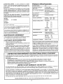
PRODUCT SPECIFICATIONS
CONGRATULATIONS
on your purchase of a Sears
Tractor. it has been designed, engineered and manufactured to give you the best possible dependability and
performance.
Should you experience any probtem you cannot easily
remedy, please contact your nearest Sears Authorized
Service CentedDepartmenL
We have competent, welltrained technicians and the proper tools to service or repair
this tractor.
Please read and retain this manual. The instructions will
enable you to assemble and maintain your tractor properly.
Always observe the "SAFETY RULES".
MODEL
NUMBER
HORSEPOWER:
19.5
GASOLINE CAPACITY
AND TYPE:
3.5 GALLONS
UNLEADED REGULAR
OIL TYPE (APt-SF/SG/SH):
SAE 30 (above 32°F)
SAE 5W-30 (below 32°F)
OIL CAPACITY:
&0 PINTS
SPARK PLUG:
(GAP: 030")
CHAMPION RJ19LM
VALVE CLEARANCE:
INTAKE:
EXHAUST:
GROUND SPEED (MPH):
FORWARD:
1st
2nd
3rd
4th
5th
6th
REVERSE:
...,'4
917o259560
SERIAL
NUMBER
DATE OF PURCHASE
THE MODELAND
ON
A PLATE
SERIAL NUMBERS"WILL
UNDER
BE FOUND _
THE SEAT.
YOU SHOULD RECORD BOTH SERIAL NUMBER AND
DATE OF PURCHASE AND KEEP IN A SAFE PLACE
FOR FUTURE REFERENCE.
MAINTENANCE
AGREEMENT
A Sears Maintenance
Agreement
uct, Contact your nearest Sears
CUSTOMER
•
Read and observe the safety rules.
FoJlow a regu}ar schedule in maintaining, cadng for and
using your tractor.
,
Followthe instructions under"Customer Responsibilities" and "Storage" sections of this owner's manual.
WARNING:
This tractor is equipped with an internal
combustion engine and should not be used on or near any
unimproved forest-covered, brush-covered or grass-covered land unless the engine's exhaust system is equipped
LIMITED TWO YEAR WARRANTY
1,.1
t.5
23
35
4.4
57
1.7
TIRE PRESSURE:
FRONT:
REAR:
CHARGING SYSTEM:
3 AMPS BATTERY
5 AMPS HEADLIGHTS
BATTERY:
AMPtHR:
MIN, CCA:
CASE SIZE:
BLADE BOLT TORQUE:
30-35 FT, LBS,
is available on this prodstore for details°
RESPONSIBILITIES
.004" - .006"
.007" - .009"
14 PSI
10 PS1
30
240
U1R
with a spark arrestor meeting applicable local or state laws
(if any). If a spark arrestor Js used, Jt should be maintained
in effective working order by the operator°
In the state of California the aboveqs required by law
(Section 4442 of the California Pubtic Resources Code).
Other states may have similar laws,, Federal laws apply on
federal lands. A spark arrester for the muffler is available
through your nearest Sears Authorized Service Center/
Department (See REPA1R PARTS section of this manual).,
ON CRAFTSMAN
RIDING EQUIPMENT
For two (2) years from the date of purchase, if this Craftsman Riding Equipment is maintained, lubricated and tuned up according
to the instructions in the owner's manual, Sears will repair or replace, free of charge, any parts found to be detective in material or
workmanship.
This Warranty does not cover:
•
Expendable items which become worn during normal use, such as blades, spark plugs, air cleaners, belts, etc.
o
Tire replacement or repair caused by punctures from outside objects, such as nails, thorns, stumps, or glass.
•
Repairs necessary because of operator abuse, negligence, improper storage or accident or the failure to maintain the
equipment according to the instructions contained in the owner's manual.
.
Riding equipment used for commercial or rental purposes.
LIMITED 90 DAY WARRANTY
ON BATTERY
For ninety (90) days from date of purchase, if any battery included with this dding equipment proves defective in material or
workmanship and our testing determines the battery will not hold a charge, Sears will replace the battery at no charge
1N-HOME WARRANTY SERVICE ON YOUR CRAFTSMAN RIDING EQUIPMENT IS AVAILABLE AT NO-CHARGE FOR 30
DAYS FROM THE DATE OF PURCHASE, PLEASE CONTACT YOUR NEAREST SERVICE CENTER AFTER 30 DAYS FROM
THE DATE OF PURCHASE, WARRANTY SERVICE IS AVAILABLE BY TAKING YOUR CRAFTSMAN RIDING EQUIPMENT TO
YOUR NEAREST SEARS SERVICE CENTER, (IN-HOME WARRANTY SERVICE WILL STILL BE AVAILABLE AFTER 30 DAYS
FROM THE DATE OF PURCHASE BUT A STANDARD TRIP CHARGE WILL APPLY.) THIS WARRANTY APPLIES ONLY
WHILE THIS PRODUCT IS IN THE UNITED STATES.
This Warranty gives you specific legal rights, and you may also have other rights which may vary from state to state.
SEARS,
....
_
ROEBLJCK
AND CO,, D/817 WA, HOFFMAN
...................................
ESTATES,
IL 60179
iii1!
3
II
IL'I'II ....
ii
,i,
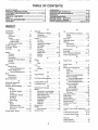
TABLE OF CONTENTS
SAFETY RULES ............................................................
2
PRODUCT SPECIFICATIONS ...................................... 3
CUSTOMER RESPONSIBILITIES ..................... 3, 15-19
WARRANTY ..................................................................
3
TABLE OF CONTENTS ................................................ 4
INDEX ............................................................................
4
TRACTOR ACCESSORIES .......................................... 5
ASSEMBLY ................................................................
7-9
OPERATION ...........................................................
10-14
MAINTENANCE SCHEDULE ...................................... 15
SERVICE AND ADJUSTMENTS ............................ 20-25
STORAGE ...................................................................
26
TROUBLESHOOTING ............................................ 27-28
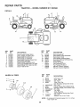
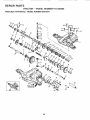
REPAIR PARTS - TRACTOR ................................. 30-47
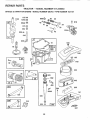
REPAIR PARTS - ENGINE .................................... 48-53
PARTS ORDERING/SERVICE .................. BACK PAGE
iNDEX
Battery:
Charging ................................................
7-8
Cieaning ......................................
17
Connecting .................................. 7-8
Starting with Weak Battery ...........23
Storage ........................................ 26
Terminals ............................................
17
Belts:
Motion Drive
Removal/Replacement .............22
Mower Blade Drive
Removal/Replacement ............. 22
Blade:
Sharpening ..........................................
t6
Replacement ....................................16
Brake Adjustment ................................. 22
C
Carburetor Adjustment ........................ 25
Controls, Tractor .................................... 1t
Customer Responsibilities ...............15-19
Engine:
Air Filter ...................................
18
Air Screen, Engine .................... 18
Battery ............................................17
Cooling Fins, Engine ................. 18
Engine Oil ......................................
17
Fuel Filter _.....................................19
Spark Plugs ...................................19
Tractor:
Blades ..................................... 16
Lubrication Chart .........................15
Maintenance Schedule ..............15
Tire Care .......................... 8,t6,23
Cutting Height, Mower ....................... 12
E
O
Electrical:
Oil:
Interlocks and Relays ....................24
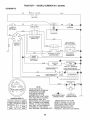
Schematic ...........................................
29
Widng Diagram ...............................30
Engine:
Air Filter...........
;.................................... 18
Air Screen .............................................
18
Cooling Fins, Engine .........................
18
Oil Change ........................................17
Oil Level ..................................... 13,17
Oil Type ..............................................17
Preparation ......................................13
Repair Parts .................................
48-53
Starting ...............................................14
Storage ................................................
26
Cold Weather Conditions ........ 13,17
Engine .......................................................
17
Storage ....................................................
26
Operation ...................................................
11-14
Operating Mower .................................. 13
Options:
Accessories .................................... 5
Spark Arrester ............................ 3,40
P
Parking Brake ..............................................
11-12
Parts Bag ...........................................................
6
Pads, ReplacemenlJRepair ................
30-47
Product Specifications ......................................
3
F
Filters:
Air. ........................................................
18
Fuel .........................................................
19
Fuel:
Type .......................................................
13
Storage ...............................................
26
Fuse
24
.......................................................
A
Accessories .................................................5
Adjustments:
Brake .......................................................
22
Carburetor- .............................................
25
Mower:
Front-To-Back ........................1o.21
Side*To-Side .....................................
21
Throttle Control Cable ....................24
Air Filter, Engine .................................... 18
Air Screen, Engine .............................. 18
Assembly ............................................. 7-9
B
G
Gauge Wheels ....................................... 8
H
Hood Removal/Installation
....................24
L
Leveling Mower Deck ..............................21
Lubrication Chart ................................... 15
M
Maintenance Schedule .............................
15
Mower:
Adjustment, Front4o-Back ........... 21
Adjustment, Side-to*Side ............ 21
Blade Sharpening ............................16
Blade Replacement ..........................16
Cutting Height ................................ 12
Installation ............................................
20
Operation ...................................... 13
Removal ...........................................20
Mowing Tips .................................................
14
Mufftet. ........................................................
t9
Spark Arrester ...............................3,40
Mulcher Plate .............................................
9
R
Repair Parts ..........................................
30-47
S
Safety Rules ........................................................
2
Seat ...............................................................8
Service and Adjustments ................ 20-25
Brake .......................................................
22
Carburetor'. ......................................................
25
Fuse ............................................................
24
Hood Removal/Installation ............24
Mofion Drive Belt
Removal/Replacement
........... 22
Mower Blade Drive Bel!
Removal/Replacement
...................
22
Mower Adjustment:
Front*to-Back ........................... 21
Side-to-Side ........................................
21
Mower Installation .................................
20
Mower' Removal ............................. 20
Tire Care ..................................8,16,23
Slope Guide Sheet ..................................55
Spark Plugs ..............................................19
Specifications .........................................................
3
Starling the Engine ........................ 13-14
Steering Wheel ......................................7,23
Stopping the Tractor ....................................
12
Storage ......................................................26
T
Throttle Control Cable Adjustment ..... 24
Tires .....................................................
8,16,23
Trouble Shooting Chart ............................
27-28
Transaxle Repair Parts .........................
46-47
W
Warranty ..................................................... 3
Wiring Diagram .........................................
30
Wiring Schematic .................................. 29
4
i ,
,i....................
, i ii,llll,l,,n,i
ACCESSOR
........illl,ll,lll,
iir
i,l_,lll
i
, nlll,lll,,,,,ll,l,nlll,,,i,,n,,lll
AND ATTACHMENTS
Li ll,i I,II,,H
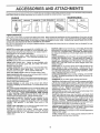
These accessories and attachments were available through most Sears retail outlets and service centers when the tractor was purchased.,
Most Sears stores can order these items for you when you provide the model number of your tractor,
MAINTENANCE
ENGINE
SPARK PLUG
GAS CAN
ENGINE OIL
FUEL STABILIZER
AIR FILTER
BLADES
BELTS
%
PERFORMANCE
Sears offers a wide variety of attachments that fit your tractor. Many of these are fisted below with brier explanations of how they can help
you. Th s list was current at the time of publication; however, it may change in future years - more attachments may be added, changes
may be made in these attachments, or some may no longer b_ available or fit your model, Contact your nearest Sears store for the
accessories and attachments
that' are a_vailable for your tractor.
• Most of these attachments do not require additional hitches or conversion kits (those that do are indicated) and are designed for easy
attaching and detaching
SNOW BLADE for snow removal only. 14-inch high, 48-inch wide
blade clears 42-inch path when angled left or right. Raises, lowers
with side Iever.. Adjustable skids; replaceable, reversible scraper
bar. (Use with tire chains and wheel weights andtor rear drawbar
weighL)
SNOWTHROWER has 40-inch swath. Drum-type auger handles
powdery and wet/heavy snow. Mounts easily with simple pin
arrangement. Discharge chute adjusts from tractor seat. 6-inch
diameter spout discharges snow 10 to 50 feet. Lift controlled at
tractor seat. (Use with chains and wheel weights and/or rear
drawbar weight.)
SPRAYERS use 12-volt DC electric motor that connects to the
tractor battery or other 12-volt source
includes booms for
automatic spraying and hand held wand for spot spraying.. Wand
has adjustable spray pattern
For applying herbicides, insectF
cides, fungicides and liquid fertilizers,
SPREADER/SEEDERS
make seeding, fertilizing, and weed killing easy, Broadcast spreaders are also useful for granular deicers and sand.
AERATOR promotes deep root growth for a healthy lawn, Tapered 2,5-inch steet spikes mounted on 10-inch diameter discs
puncture holes in soil at close intervals to let moisture soak in.
Steel weight tray for increased penetration.
BAGGER lets you collect
grass clippings and leaves for a
_healthier, neater looking lawn, Two Permanex containers hold
30-gallon plastic bags..
BUMPER protects front end of tractor from damage.
CARTS make hauling easy. Variety of sizes avaitable, plus
accessories such as side panel kits, tool caddy, cart cover,
protective mat and doily,.
CORING AERATOR takes small plugs out of soil to allow moisture and nutrients to reach grass roots.. 36-inch swath. 24
hardened steel coring tips_ t50 tb,.capacity weight tray.
EASY OIL DRAIN VALVE makes oil changes easier, faster.
FRONT NOSE ROLLER canters in front of mower deck to reduce
chances of "scalping" on uneven terrain.
GANG HITCH lets you tow 2 or3 pull-behind attachments at once,
such as sweepers, dethatchers, aerators (not for use with rollers,
carts or other heavy attachments)_
GAUGE WHEELS on both sides of the mower deck reduce
chances of "scalping" on uneven terrain, For mower decks not so
equipped.
MULCH RAKE/DETHATCHER
loosens soil and flips thatch and
matted leaves to lawn surface for easy pickup. Twenty spring tine
teeth. Useful to prepare bare areas forseeding, Available for front
or rear mounting,
HIGH PERFORMANCE
REEL-ACTION
SPRING TINE DETHATCHER covers 36-inch wide path and
tosses thatch into farge hopper.. Mounts behind tractor.
MULCHING CLOSE-OUT PLATE KIT, once installed, lets you
mulch, discharge or bag clippings (bagger optional) without
changing blades.. For models not equipped as 3-in-1 Convertible
mowers.
See "MOWER" in the Repair Parts section of this
manual.
RAMP TOPS AND FEET let you load and unload tractor from a
pickup truck, Use with 2 x 8 or 2 x t0 lumber.
ROLLER for smoother lawn surface.
36-inch wide, 18-inch
diameterwater4ightdrum
holdsupto3901bs, ofweight. Rounded
edges prevent harm to turf Adjustable scraper automatically
cleans drum,
SWEEPERS let you collect grass clippings and leaves
TILLER has 5 hp engine and 36-inch swath to prepare seed beds,
cultivate and compost garden residue. Tiller has its own builtqn
lift and depth control system and does NOT require a sleeve hitch_
Fits any lawn, yard orgarden tractor Simply hook up to the tractor
drawbar and go!
Optional
accessories
convert unit for
dethatching, aerating, hiIfing ..without tool&.
TIRE CHAINS are heavy duty', closety spaced extra-large cross
links give smooth ride, outstanding traction..
TRACTOR CAB has heavy duty vinyl fabric over tubuEar steel
frame, ABS plastic top; clear plastic windshield offers 360 degree
visibility. Hinged metal doors with catch. Keeps operator warm
and dry. Remove vinyt sides and windshields for use as sun
protector in summer_ Optional accessories
include:
tinted/
tempered solid safety glass windshie[d with hand operated wiper;
12-volt amber caution Light for mounting on cab top.
VACS for powerful collection of heavy grass clippings and leaves
Optional wand attachment to pick up debris in hard-to-reach
places. VAC/CHIPPER includes a chipper-shredder.
WEIGHT BRACKET for drawbar for snow removal applications.
Uses (t) 55 lb, weight.
WHEEL WEIGHTS for rear wheels provide needed traction for
snow removal or dozing heavy materials,
5
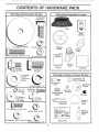
CONTENTS
Parts Bag contents
OF HA
shown full size
DWARE PACK
Parts packed separately
in carton
(1) Hex Bolt
3/8-16 x 1
©
Seat
Video
Cassette
(1) Large Flat Washer
(1) Lockwasher 3/8
11) Hex Bolt 5/16-18 x lq/4
Steering
Wheel
@
(1) Locknut
llll ii
ii ,i
i
Mulcher
Plate
5/16-18
i
t
$
Steering
Boot
Manual
(1) Shoulder
Boft 5/16-18
Parts Bag
(1) Hex Bolt
1/2-13 x 1
(1) Washer
Parts bag contents
17/32 x
1-3/!6°x 12
Gauge
$
not shown full size
©
(1) Lock Washer
(2) Washers 3/8
x 7/8 x 14 Gauge
(2) Shoulder
Bolts
1/2
(2) Gauge
Wheels
©
_@(2)
Lock
#10
x 5/8
(2)
Screws
Steering Wheel
Adapter
Was'_r 0
(2) Washers
3/16 x 3/4
x 16 Gauge
(2) Hex Bolts 1/4-20 x 3/4
(¢
(2) Washers
(2) Centerlock Nuts
,,f--_,
(2) Keys
(2) Weld
Nuts #10
"_' Latch '_Hook
Assernblys
@
"\
/
Steering
Extension
Shaft
(2) Hex Nuts 1/4-20
9/32 x 5/8 x 16 Gauge
(2) Lock Washers
Wheel
Steering
Insert
C
Slope Sheet
1/4
6
ASSENIBLY
............................................................................................
i
i
Your new tractor has been assembled at the factory' with exception of those parts left unassembled for shipping purposes,
To ensure safe and proper operation of your tractor alt parts and hardware you assemble must be tightened securelyo Use
the correct tools as necessary to insure proper tightness°
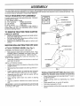
TOOLS
REQUIRED
FOR ASSEMBLY
A socket wrench set will make assembly easier. Standard
wrench sizes are listed,
(I) 3/4" Socket w/drive rachet
(2) 7/16" wrenches
Phillips Screwdriver
(2) 1/2" wrench
Tire pressure gauge
(1) 9/16" wrench
Utility knife
When right or left hand is mentioned in this manual, it
means when you are in the operating position (seated
behind the steering wheel)
LARGE FLAT
WASHER
TO REMOVE TRACTOR FROM CARTON
UNPACK
•
•
o
CARTON
STEERING
WHEEL
'
STEERING
BOOT
Remove all accessible loose parts and parts cartons
from carton (See page 6).
Cut, from top to bottom, along lines on al! four corners
of carton, and lay panels flat,,
Check for any additional loose parts or cartons and
remove°
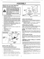
_-BEFORE ROLMNGTRACTOR
ATTACH
ASSEMBLE
STEERING
WHEEL
OFF SKID
(See Fig. 1)
EXTENSION SHAFT AND BOOT
-
Slide extension shaft onto lower steering shaft, Align
mounting holes in extension and lower shafts and
install 5/t6 hex bolt and locknuto Tighten securely_
IMPORTANT: TIGHTEN BOLT AND NUT SECURELY TO
18-22 FT, LBS TORQUE,,
°
Place tabs of steering boot over tab slots in dash and
push down to secure,
INSTALL STEERING WHEEL
o
°
Position front wheels of the tractor so they are pointing
straight forward,,
Slide steering wheel adapter onto steering shaft extension.
•
Position steering wheel so cross bars are horizontal
(left to right) and slide inside boot and onto adapter.,
.
Assemble large flat washer, 3/8 lock washer, 3t8 hex
bolt and tighten securely°
°
Snap steering wheel insert into center of steering
wheel_
FIG. 1
TO ROLLTRACTOR
section for location
Remove protective materials from tractor hood and
grill°
IMPORTANT: CHECK FOR AND REMOVE ANY STAPLES
IN SKID THAT MAY PUNCTURE TIRES WHERE TRACTOR
IS TO ROLL OFF SKID
•
Press lift lever plunger and raise attachment _ift!ever to
its highest position_
•
Release parking brake by depressing ctu_ca!brake
pedal,
Place gearshift lever in neutral (N) position,
Roll tractor backwards off skid
°
•
°
•
7
OFF SKID (See Operation
and function of controls)
Remove banding holding discharge guard up against
tractor,
LY
ASSE
HOW TO SET UP YOUR TRACTOR
CONNECT
BATTERY
SEAT
(See Fig. 2)
iiiiii i1,,i i, II
I
SEAT PAN
CAUTION: Do not short battery terminals by allowing a wrench or any other
same time. Before connecting battery,
object to metal
remove
contactbracelets,
both terminals
wristwatch
at the
bands, rings, etc.
Positive terminal must be connected
first to prevent sparking from accidental grounding.
Lift hood to raised position.
•
Open terminal access doors, remove terminal protective caps and discard
•
If this battery iS put into service after month and year,
Indicated on label (label located between terminals)
charge battery for minimum of one hour-at 6-10 amps.
•
First connect RED battery cable to positive (+) battery
terminal with hex bolt, flat washer, lock washer and hex
nut as shown. Tighten securely.
•
Connect BLACK grounding cable to negative (-) battery terminal with remaining hex bolt, flat washer, lock
washer and hex nut. Tighten securety_
•
Close terminal access doors.
Use terminal access doors for:
= Inspection for secure connections (to tighten hardware),
•
Inspection for corrosion..
= Testing battery.
= Jumping (if required).,
•
Periodic charging.
LOCK
WASHER
DISCARD TERMINAL
PROTECTIVE CAPS
,,,
FLAT
WASHER
HEX NUT
HEX
BOLT
(RED)
b
CABLE
lil
! ,
": _::
NEGATIVE
(BLACK)
CABLE
FIGo 2
•
•
CHECK TIRE PRESSURE
The tires on your tractor were ovefinflated
shipping purposes. Correct tire pressure
best cutting performance_
•
Reduce tire pressure to PSi shown
SPECIFICATIONS" on page 3 of this
at the factory for
is important for
in "PRODUCT
manual.
CHECK DECK LEVELNESS
For best cutting results, mower housing should be properly
leveled. See "TO LEVEL MOWER HOUSING" in the
Service and Adjustments section of this manual.
CHECK
BELTS
FOR
PROPER
POSITION
OF
ALL
See the figures that are shown for replacing motion and
mower blade drive belts in the Service and Adjustments
section of this manual, Verify that the belts are routed
correctly.
CHECK
BRAKE
SYSTEM
ASSEMBLE
GAUGE
DECK (See Fig. 4)
Assemble adjustment bolt, lock washer and fiat washer
loosely
Do net tighten
Tighten shoulder bolt securely,
Lower seat into operating position and sit on seat
Slide seat unlil a comior[able
position _sreached which
allows you to press clutchtbrake
oedal all the way
i! c,.*,n
_et off se2,i vltt_out moving l[s adjus_.eu position
_aise so-,: ar>d t!ghten sd;ustment bcl securely
WHEELS
TO
MOWER
The gauge wheels are designed to keep the mower deck in
proper position when operating mower. Be sure they are
properly adjusted to ensure optimum mower performance,
.
Assemble gauge wheels with tractor on a fiat level
surface
o
Adjust mower to desired cutting height (See "TO ADJUST MOWER CUTTING HEIGHT" in the Operation
section of this manual),.
o
With mower Jn desired height of cut position, gauge
wheels should be assembled so they are slightly off the
_mund Instant gauge wheel in appropriate n::_e ', :_:
shoulder bolt, 3/8 washer, and 3/8-16 locknut and
tighten securely
•
Repeat for opposite side installing gauge wheel in
_ame aalL._slmen_ioe
SEAT (See Fig, 3)
Adjust seat before tightening adjustment bolt.
= Remove cardboard packing on seat pan°
•
P;ace seat on seat pan and assemble shoulder bolt
°
°
•
FIG. 3
POSITIVE
t*
•
LOCK WASHER
After you learn how to operate your tractor, check to see
that the brake is properly adjusted,, See "TO ADJUST
BRAKE" in the Service and Adjustments section of this
manual
TERMINAL "" _t
ACCESS
DOOR
;
INSTALL
FLAT WASH ER
ADJUSTMENT
BOLT
i
i ii iiii ,11IIH"I,
ASSEM
LY
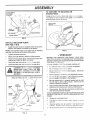
TO CONVERT TO BAGGING
DISCHARGING
GAUGE WHEEL
MOUNTING
BRACKET
OR
Simply remove muicher pla[e and store in a safe place.
Your mower is now ready for disci_arging or inslailation of
optional grass catcher accessory
DEFLECTOR
SHIELD
_-"_
/
318-16
LOCKNUT
SHOULDER
318" WASHER
BOLT
GAUGE WHEEL"
FIG. 4
INSTALL MULCHER
(See Figs. 5 & 6)
.
PLATE
LATCH
HOOKS
Install two latch hooks to mulcher plate using screw,
washer, lock washer, and weld nut as shown°
FIG. 6
_NOTE: Pre-assemble weld nut to latch hook by inserting
weld nut from the top with hook pointing down.
,
Tighten hardware securely_
•
Raise and hold deflector shield in upright position_
.
•
Place front of mulcher plate over front of mower deck
opening and slide into place, as shown
Hook front latch into hole on iront ot mower deck,,
BEFORE YOU OPERATE AND ENJOY YOUR NEW
TRA CTOR, WE WISH TO ASSURE THAT YOU RECEIVE
THE BES T PERFORMA NCEAND SATISFACTION FROM
THIS QUALITY PRODUCT
o
Hook rear latch into hole on back of mower deck_
_OLEASE REVIEW
v" CHECKLIS7
J
,_
I
,_ A
j ._
| _
CAUTION: Do not remove discharge
guard from mower,, Raise and hold
guard when attaching mulcher plate
and allow it to rest on plate while in
I ...............
operation°
,,
WELD NIL.ITFROM THE TOP
HOOK POINTS DOWN
LOCK
WASHER
WELD
NUT \\_\
SCREW
LATCH
HOOK
WELD
NUT
!
Ail :_ssembly instructions have been completed.
v"
No rem,aining loose parts in carton.
/
Battery is property oreoared and charged°
t hou(at 6 a;-rcs.
,/
Seat is adjusted comfortably and tightened securely,
,/
Ait tires are properly irfflated (For shipping purposes,
the tires were overinflated a[ the factory)_
,/
Be sure mower deck is properly leveled side-to-side/
fronbto-rear for best cutting results. (Tires must be
properly inflated for leveling)
¢"
Check mower and drive belts. Be sure they are routed
properly around pulleys and inside all belt keepers,
,/
Check wiring See that al! connections are still secure
and wires are properly clamped.
FIGo 5
(Minimum
WHILE LEARNING HOW TO USE YOUR TRACTOR, PAY
EXTRA A TTENTION TO THE FOLL OWING fMPORTANT
ITEMS:
,/
Engine oil is at proper level
,/
Fuel lank is iiited _._.._;t_
treslq, clean, regutar un_eaueo
gasoline
Become familiar w_iq all controls - [heir loca!._on an(]
function Operate them before you start the e_o,ine
v"
,
MULCHER
PLATE
CHECKLIST:
,/
V
WASHER
i
J
THE FOLLOWING
Be sure orake system Js Jnsate operailng COndiil0_
OPERATION
These symbols may appear on your tractor or in literature supptied with the product. Learn and understand their meaning,,
4'
BATTERY
CAUTION OR
WARNING
REVERSE
FORWARD
FAST
SLOW
ENGINE ON
ENGINE OFF
OIL PRESSURE
CLUTCH
LIGHTS ON
LIGHTS OFF
MOWER HEIGHT
DIFFERENTIAL
LOCK
PARKING BRAKE
LOCKED
UNLOCKED
X
FUEL
CHOKE
L
REVERSE
MOWER LIFT
NEUTRAL
ATTACHMENT
CLUTCH ENGAGED
HIGH
LOW
ATTACHMENT
CLUTCH DISENGAGED
PARKING BRAKE
IGNITION
HYDROSTATIC FREE WHEEL
(Hydro Models only)
DANGER, KEEP HANDS AND FEET AWAY
10
OPERATION
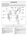
KNOW YOUR TRACTOR
READ THIS OWNER'S
MANUAL
AND SAFETY
RULES BEFORE
OPERATING
YOUR TRACTOR
Compare the illustrationswith your tractor to familiarize yourself with the locations of various controls and adjustments. Save
this manual for future reference.
ATTACHMENT
CLUTCH LEVER
LIGHT SWITCH
POSITION
IGNITION
SWITCH
AMMETER
THROTTLE
CONTROL
ATTACHMENT
LIFT LEVER
CLUTCHtBRAKE
PEDAL
PARKING
BRAKE
HEIGHT
ADJUSTMENT
KNOB
GEARSHIFT
LEVER
FIG. 7
Our tractors conform to the safety standards of the American National Standards Institute
GEARSHIFT LEVER: Selects the speed and direction of
tractor,
ATTACHMENT LIFT LEVER: Used to raise and lower the
mower deck or other attachments mounted to your tractor_
LIFT LEVER PLUNGER: Used to release attachment lift
lever when changing its position.
ATTACHMENT CLUTCH LEVER: Used to engage the
mower blades, or other attachments mounted to your
tractor.
LIGHT SWITCH:
THROTTLE
Turns the headlights on and ofL
CONTROL:
CHOKE CONTROL:
Used to control engine speed,
Used when starting a cold engine.
IGNITION SWITCH:
engine,
CLUTCH/BRAKE PEDAL: Used for decfutching and brak_
ing the tractor and starting the engine.
PARKING BRAKE: Locks clutch/brake pedal into the
brake position,
Used for starting and stopping the
HEIGHT ADJUSTMENT KNOB: Used to adjust the mower
cutting height,
AMMETER:
(-),
11
Indicates battery charging (+) or discharging
OPEl ATION
,
iiii
II
I
III
i1,1111111
,
i
IIII
,
tttlllLt
...................................
The operation of any tractor can result in foreign objects thrown into the eyes, which can
result in severe eye damage. Always wear safety glasses or eye shields while operating your
tractor or performing any adjustments or repairs. We recommend a wide vision safety mask
over the spectacles or standard safety glasses.
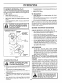
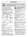
HOW TO USE YOUR TRACTOR
TO SET PARKING
BRAKE
CAUTION: Always stop tractor completely, as described above, before leaving the operator's position; to empty
grass catcher', etc.
(See Fig. 8)
Your-tractor isequipped with art operator presence sensing
switch.. When engine is running, any attempt by the
operator to leave the seat without first setting the parking
brake will shut off the engine°
TO USE THROTTLE
•
Depress clutch/brake pedal into full ".BRAKE" position :
and hold,
°
•
Place parking brake lever' in "ENGAGED" position and
release pressure from clutch/brake pedal, Pedal should
remain in "BRAKE" position. Make sure parking brake
will hold tractor secure.
•
THROTTLE
CONTROL
ATTACHMENT CLUTCH LEVER
"ENGAGED"
POSITION
"DISENGAGED"
POSITION
HEIGHT' ADJUSTMENT
TO USE CHOKE CONTROL
(See Fig. 8)
KNOB
(See Fig. 8)
MOWER BLADES °
Move attachment clutch lever to "DISENGAGED"
sition.
GROUND DRIVE -
To engage choke control, pull knob out, Slowly push
knob in to disengage_
TO MOVE FORWARD
AND BACKWARD
(See Fig. 8)
is controlled by the
°
Start tractor with clutch!brake pedal depressed and
gearshift lever in neutral (N) position.
o
Move gearshift and range shift levers to desired posilion.
°
Slowly release clutch/brake
pedal to start movement.
IMPORTANT:
BRING TRACTOR TO A COMPLETE STOP
BEFORE SHIFTING
OR CHANGING
GEARS. FAILURE
TO DO SO WILL SHORTEN THE USEFUL LIFE OF YOUR
TRANSAXLE,.
FIG. 8
STOPPING
Operating engine at less than full throttle reduces the
battery charging rate.
Full throttle offers the best bagging and mower performance,
The direction and speed of movement
gearshift lever'.
GEARSHIFT
LEVER
CLUTCHtBRAKE PEDAL
"DRIVE" POSITION
Always operate engine at full throttle.,
°
PARKING BRAKE
"ENGAGED"
POSITION
"BRAKE"
POSITION
(See Fig. 8)
Use choke control whenever you are starting a cold engine_.
Do not use to start a warm engine,
"DISENGAGED"
POSITION
CHOKE
CONTROL
CONTROL
TO ADJUST MOWER
(See Fig. 8)
po-
Depress clutch/brake pedal into full "BRAKE" position.
°
Move gearshift lever to neutral (N) position,
ENGINE °
Move throttte control to slow (',_!,) position_
NOTE: Failure to move throttle control to slow (,,_)
position and allowing engine to idle before stopping may
cause engine to "backfire".
= Turn ignition key to "OFF" position and remove key,
Always remove key when leaving tractor to prevent
unauthorized use.
CUTTING
HEIGHT
The cutting height is controlled by tumir_g the height adjustment knob in desired direction.
=
Turn knob clockwise (("_)
°
Turn knob counterclockwise
height.
to raise cutting height
(!_'-",0 to lower cutting
The cutting height range is approximately 1-1/2" to 4".. The
heights are measured from the ground to the blade tip with
the engine not running, These heights are approximate
and may vary depending upon soil conditions, height of
grass and types of grass being mowed.
•
°
Never use choke to stop engine.
NOTE: Under certain conditions when tractor is standing
•
idle with the engine running, hot engine exhaust gases may
cause "browning" of grass. To eliminate this possibility,
always stop engine when stopping tractor on grass areas, 12
The average lawn should be cut to approximately 2-1/2
inches during the cool season and to over 3 inches
during hot months. For healthier and better looking
lawns, mow often and after moderate growth.
For best cutting performance, grass over6 inches in
height should be mowed twice.. Make the first cut
relatively high; the second to desired height°
OPERATION
TO OPERATE
MOWER
(See Fig. 9)
Your tractor is equipped with an operator presence sensing
switch, Any attempt by the operator to leave the seat with
the engine running and the attachment clutch engaged wilt
shut off the engine.
•
To restart movement, slowly release parking brake and
clutch/brake pedal,
°
Make all turns slowly.
.
°
Select desired height of cuL
Lower mower with attachment lift control.
o
Raise attachment lift to highest position with attachment lift control_
o
Start mower blades by engaging attachment clutch
control.
•
When pushing or towing your tractor, be sure gearshift
lever is in neutral (N) position.
•
TO STOP MOWER BLADES - disengage attachment
clutch control
°
Do not push or tow tractor at more than five (5) MPH,
TO TRANSPORT
NOTE: To protect hood from damage when transporting
your tractor on a truck or a t railer, be sure hood isclosed and
secured to tractor, Use an appropriate means of tying hood
to tractor (rope, cord, etc)_
1...........
,_
..... CAUTION: D'o not operate the mower
I ,_j_.
without eitherthe entire grass catcher,
| _
on mowers so equipl_ei:t, or the dis-.
t _
BEFORE STARTING THE ENGINE
guard in place.
CHECK
ATTACHMENT CLUTCH LEVER
"DISENGAGED"
POSITION
\
ENGINE
OIL LEVEL (See Fig. 15)
°
The engine in your tractor has been shipped, from the
factory, already filled with summer weight oil
•
Check engine oil with tractor on level ground,
°
Remove oil fill cap/dipstick and wipe clean, reinsert the
dipstick and screw cap tight, wait for a few seconds,
remove and read oil level If necessary, add oil until
"FULL" mark on dipstick is reached,. Do not overfill,
°
For cold weather operation you should change oil for
easier starting (See "OIL VISCOSITY CHART" in the
Customer Responsibilities section of this manual),
o
To change engine oil, see the Customer Responsibilities section in this manual.
ATTACHMENT
ADD GASOLINE
°
Fill fuel tank. Use fresh, clean, regular unieaded
gasoline with a minimum of 87 octane (Use of leaded
gasoline will increase carbon and lead oxide deposits
and reduce valve life) Do not mix oil with gasoline.
Purchase fuel in quantities that can be used within 30
days to assure fuel freshness.
IMPORTANT: WHEN OPERATING IN TEMPERATURES
BELOW 32°F(0°C), USE FRESH, CLEAN WINTER GRADE
GASOLINE TO HELP INSURE GOOD COLD WEATHER
STARTING.
FIG. 9
TO OPERATE
WARNING:
Experience indicates that alcohol blended
fuels (called gasohol or using ethanol or methanol) can
attract moisture which leads to separation and formation of
acids during storage_ Acidic gas can damage the fuel
system of an engine while in storage_ To avoid engine
problems, the fuel system should be emptied before storage of 30 days or Iongen Drain the gas tank, start the
engine and let it run until the fue! lines and carburetor are
empty. Use fresh fuel next season, See Storage lnstruc _
tions for additional information
Never use engine or
carburetor cleaner products in the fuel tank or permanent
damage may occur
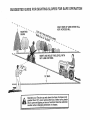
ON HILLS
hills with slopes greater than 15 ° and
CAUTION:
not drive
up or down
do not drive Do
across
any slope.
'"""_
.....
,,,,, ,,,
iii,
i
,
Choose the slowest speed before starting up or down
hills
o
Avoid stopping or changing speed on hills.
°
If slowing is necessary, move throttle control lever to
slower position..
-
If stopping is absolutely necessary, push clutch/brake
pedal quickly to brake position and engage parking
brake.
i,
•
Move gearshift lever to 1st gear. Be sure you have
allowed room for tractor to roll slightly as you restart
movement,
iii
iiii
................
:1 ,lul,i
filler neck. Do not overfill. Wipe off any
CAUTION:
bottom
of gas
spilled
oil orFill
fuel.to Do
not store,
spilltank
or
use gasoline near an open flame.
13
i
OPERAT!ON
TO START
ENGINE
(See Fig. 8)
When starting the engine for the first time or if the engine
has run out of fuel, it will take extra cranking time to move
fuel from the tank to the engine.
.
Sit on seat in operating position, depress clutch/brake
pedal and set parking brake,
Place gear shift lever in neutral (N) position.
•
Move attachment clutch to "DISENGAGED" position_
o Move throttle control to fast (.f_) position
•
Pull choke control out for a cold engine start attempt,
For a warm engine start attempt the choke control may
not be needed.
Note: Before starting, read the warm and cold starting
procedures below.
°
Insert keyinto ignition and turnkeyclockwise to"START"
position and release key as soon as engine starts. Do
not run starter Con!inuously for more than fifteen seconds per minute. If the engine doits not start after
severat attempts, push choke control in, wait a few
minutes and try again If engine still does not start, pull
the choke control out and retry.
WARM WEATHER STARTING (50 ° F and above)
.
When engine starts, slowly push choke control in until
the engine begins to run smoothly. If the engine starts
to rl-n roughly, pull the choke control out slightly for a
row seconds and then continue to push the control in
slowly.
,
The attachments and ground drive can now be used.: If
the engine does not accept the load, restart the engine
and allow it to warm up for one minute using the choke
as described above.
•
°
•
°
FIG. 10
MULCHING
•
slowly. This may require an engine warm-up period
from several seconds to several m{,_utes, depending
on the temperature_
°
The attachments can be used during the engine warmup period and may require the choke control be pulled
out slightly.
NOTE: If at a high altitude (above 3000 feet) or in cold
temperatures (below 32 F) the carburetor fuel mixture may
need to be adjusted for best engine performance. See "TO
ADJUST CARBURETOR" in the Service and Adjustments
section of this manual.
•
•
°
•
•
o
•
°
TIPS
Tile chains cannot be used when the mower housing is
attached to tractor..
Mower should be properly leveled for best mowing
performance. See "TO LEVEL MOWER HOUSING" in
the Service and Adjustments section of this manual.
The left hand side of mower should be used for trimming_
Drive so that clippings are discharged onto the area
that has been cut. Have the cut area to the right of the
tractor. This wilt result in a more even distribution of
clippings and more uniform cutting.
When mowing large areas, start by turning to the right
so that clippings wilt discharge away from shrubs,
fences, driveways, etc After one or two rounds, mow
MOWING
TIPS
IMPORTANT:
FOR BEST PERFORMANCE,
KEEP
MOWER HOUSING FREE OF BUILT-UP GRASS AND
TRASH. CLEAN AFTER EACH USE
COLD WEATHER STARTING (50 ° F and below)
o When engine starts, slowly push choke coa_rol in until
the engine begins to run smoothly_ Continue topush
the choke control in small steps allowing the engine to
accept small changes in speed and load, until the
choke control is fully in. If the engine starts to run
roughly, pull the choke control out slight}y for a few
seconds and then continue to push the ccntrot in
MOWING
in the opposite direction making left hand turns until
finished (See Fig. 10 )
tf grass is extremely tall, it should be mowed twice to
reduce load and possible fire hazard from dried clippings. Make first cut relatively high; the second to the
desired height
Do not mow grass wt_en it is wet. Wet grass will plug
mower and leave undesirable clumps_ Allow grass to
dr,/before mowing
Always operate engine at full throttle when mowing to
assure better mowing performance and oroper discharge of material, Regulate ground specs by selecting a low enough gear to give the mower cutting
performance as well as the quality of cut desired.
When operating attachments, select a ground speed
that will suit the terrain and give best performance of
the attachment being used.
°
The special mulching blade will recut the grass clippings many times and reduce then] in size so that as
they fall onto the lawn they wilt disperse into the grass
and not be noticed. Also, the mulched grass will
blodegrade qulck_y to provrde nutrrents for the la n.
Always mulch with your highest engine (blade) speed
as this will provide the best recutting action of the
blades_
Avoid cutting your lawn when it is wet. Wet grass tends
to form clumps and interferes with the mulching action,
The best time to mow your lawn is the early afternoon.
At this time the grass has dried and the newly cut area
will not be exposed to the direct sun.
For best results, adjust the mowercutting height so that
the mower cuts off only the top one-third of the grass
blades (See Fig, 11) For extremely heavy mulching,
reduce your width of cut and mow slowly.
Certain types of grass and grass conditions may require that an area be mulched a second time to completely hide the clippings. When doing a second cut,
mow across or perpendicular to the first cut path_
Change your cutting pattern from week to week° Mow
north to south one week then change to east to west the
next week. This will help prevent matting and graining
of the lawno
MAX 1/3
14
FIGo 11
CUSTO
ESPO
LITIES
SC. DU' ..............
7 e.<_"_-'_,_ SERVICE DATES J
Check
Brake Operation
Check
Tire Pressure
v"
_#'
e#1'
Check for Loose Fasteners
R
I
sharpeniReplaCe
Mower
........
BIades
-Lubrication.(_.hart
....
_f
_/
Check Ba!tery LevellRecharge
0
Clean Battery and Terminals
_
R
Check Transaxle
_-J
Cooling
Adjust Blade Belt(s)Ter_sion
....'"4
Check
Change
E
N
G
I
,L
Tension
,
_61#
5
.......
V'
!
Oil
Clean Air Filter
V'=
Clean Air Screen
inspect MuiflertSpark
Replace
v'
Arrester
.J
Oil Filter (if equipped)
Clean Engine Cooling
Fins
Replace
Spark Plug
Replace
Air Filter Paper Cartridge
Replace
Fuel Filter
l
l
...................
v'=
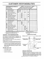
t * Change more oten when operating under a heavy load or in high ambient temperatures,
2 - Service more olten when operatng in dirt,./or dusty conditions
3 - If equipped wilh oil liter, change eli eve_,i 50 hours
4 -Repface blades mo_'e ellen when mowieg in sandy soil
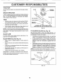
GENERAL
.........
{_/'s
Engine Oil Level
Engine
: _
_/
T
Adjust Motion Drive Bel(s)
"_1'7
_/4
5- I1equipped with adjuslable system
6 - Not required it equipped wilh mainlenance-free battery
7 * Tighten trent axIe pivot bolt to 35 ft Abs maximum
De nol ovmlighten
RECOMMENDATIONS
The warranty on this tractor does not cover items that have
been subjected to operator abuse or negligence.. To
receive full value from the warranty, operator must maintain
tractor as instructed in this manual
Some adjustments will need to be made periodically to
properly maintain your tractor.
All adjustments in the Service and Adjustments section of
this manual should be checked at least once each season.
o
®
Once a year you should replace the spark plug, clean
or replace air filter, and check blades and belts for
wear. A new spark plug and clean air filter assure
proper air-fuel mixture and help your engine run better
and last longer.
BEFORE
CLUTCH
PIVOT(S)
EACH USE
o
,
Check engine oil level
Check brake operation.
°
-
Check tire pressure..
Check for loose fasteners.
IEARSHIFT
PIVOTS
(_)
(_) SAE 30 OR 10W30 MOTOR OIL
(_) GENERAL PURPOSE GREASE
(_) REFER TO CUSTOMER RESPONSIBILITIES
"ENGINE" SECTION
IMPORTANT:
DO NOT OIL OR GREASE THE PIVOT POINTS
WHICH HAVE SPECIAL NYLON BEARINGS
VISCOUS
LUBRICANTS WILL ATTRACT DUST AND DIRT THAT WILL SHORTEN
THE LIFE OF THE SELF-LUBRICATING
BEARINGS.
IF YOU
FEEL THEY MUST BE LUBRICATED,
USE ONLY A DRY. POW15
DERED
GRAPHITE
TYPE
LUBRICANT
SPARINGLY
CUSTOM
RESPONSm ILITHES
TRACTOR
BLADE
Always observe safety rules when performing any maintenance.
BRAKE
MANDREL
OPERATION
If tractor requires more than six (6) feet stopping distance
at high speed in highest gear, then brake must be adjusted.
(See "TO ADJUST BRAKE" in the Service and Adjustmerits section of this manual),
TRAILING
EDGE
FLAT WASHER
"]'IRES
LOCK WASHER _,_
•
Maintain proper air pressure in all tires (See "PRODUCT SPECIFICATIONS" on page 3 of this manual)_
HEX BOLT
=
Keep tires free of gasoline, oil, or insect control chemicals which can harm rubber.
(GRADE 8)*
.
Avoid stumps, stones, deep ruts, sharp objects and
other hazards that may cause tire damage_
*A GRADE S HEAT TREATED BOLT CAN BE
IDENTIFIED BY SIX LINES ON THE BOLT HEAD,,
FIG. 12
NOTE: To seal tire punctures and prevent flat tires due to
slow leaks, tire sealant may be purchased from your local
parts dealer. Tire sealant also prevents tire dry rot and
corrosion°
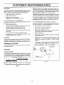
BLADE
TO SHARPEN
BLADE (See Fig. 13)
Care should be taken to keep the blade balanced,, An
unbalanced blade will cause excessive vibration and eventual damage to mower and engine,
CARE
For best results mower blades must be kept sharp. Replace bent or' damaged blades.
°
The blade can be sharpened with a file or on a grinding
wheel. Do not attempt to sharpen while on the mower,
BLADE REMOVAL
.
To check blade balance, you wilt need a 5/8" diameter
steel bolt, pin, or a cone balancer. (When using a cone
balancer, follow the instructions supplied with balancer)_
.
SWe blade on to an unthreaded portion of the steel bolt
or pin and hold the bolt or pin parallel with the ground,
If blade is balanced, it should remain in a horizontal
position. If either end of the blade moves downward,
sharpen the heavy end until the blade is balanced_
(See Fig. 12)
-
Raise mower to highest position to allow access to
blades.
•
Remove hex bolt, lock washer and flat washersecuring
blade.
=
lnstatt new or resharpened blade with trailing edge up
towards deck as shown,,
.
Reassemble hex bolt, lock washer and flat washer in
exact order as shown.
NOTE: Do not use a nail for' balancing blade. The lobes of
the center hole may appear to be centered, but are not
° Tighten bolt securefy (30-35 FL Lbso torque)_
IMPORTANT: BLADE BOLT IS GRADE 8 HEATTREATED,
CENTER
NOTE: We do not recommend sharpening blade- but if you
do, be sure the blade is balanced,
HOLE
BLADE
5f8" BOLT
OR PiN
FIG. 13
16
ESPON
CUSTO
ILnTIES
n
NOTE: Although multi-viscosity oils (5W30, 10W30 etc )
improve starting in cold weather, these multi-viscosity oils
will result in increased oil consumption when used above
32°F. Check your engine oil level more frequently to avoid
possible engine damage from running low on oii,
BATTERY
Your tractor has a battery charging system which is sufficient for normal use, However, periodic charging of the
batter), with an automotive charger will extend its life,
=
Keep battery and terminals clean,
.
Keep battery bolts tight,
-
Keep small vent holes open,
•
Recharge at 6-10 amperes for 1 hour.
Change the oil after every 25 hours of operation or at least
once a year if the tractor is not used for 25 hours in one year,
Check the crankcase oil level before starting the engine
and after each eight (8) hours of operation. Tighten oil fill
cap/dipstick securely each time you check the oil level,
TO CLEAN BATTERY AND TERMINALS
Corrosion and dirt on the batter/and
the battery to "leak" power°
TO CHANGE ENGINE OfL (See Figs. 14 and 15)
terminals can cause
Determine temperature range expected before oil change,
All oil must meet API service classification SF SG or SH
o
Remove terminal guard,,
o
Disconnect BLACK battery, cable first then RED battery cable and remove battery fr'orn tractor,
°
Be sure tractor
Rinse the battery with plain water and dry_
•
°
Oil will drain more freely when warm.
Catch oil in a suitable container,
•
Clean terminals and battery cable ends with wire brush
until bright,
°
Remove oil fill cap/dipstick, Be careful not to allow dirt
to enter the engine when changing oil,
•
Coat terminals with grease or petroleum jelly°
•
Remove drain plug
.
Reinstall battery (See "CONNECT BATTERY" in the
Assembly section of this manual),
°
After oil has drained completely, replace oil drain plug
and tighten securely
°
Refill engine w!tP.oil through oil fill di_)stick tube. Pour
slowly. Do n ',overfill For approxir ate capacity see
"PRODUCT SPECIFICATIONS" on page 3 of this
manual.,
°
Use gauge on oil fill cap/dipstick for checking tevel Be
sure dipstick cap is tightened securely for accurate
reading, Keep oil at "FULL" line on dipstick,
-_
V-BELTS
Check V-belts for deterioration and wear after 100 hours of
operation and replace if necessary. The belts are not
adjustable, Replace belts if they begin to slip from wean
TRANSAXLE
COOLING
is on level surface.
Keep transaxle free from build-up of dirt and chaff which
can restrict cooling,,
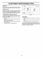
AIR SCREEN
OIL
DRAIN
PLUG
ENGINE
LUBRICATION
Only use high quality detergent oil rated with API service
classification SF, SG or SH. Select the oil's SAE viscosity
grade according to your expected operating temperature.
.......
0F
°c
OIL FILL
CAPiDIPSTSICK
SAE VISCOSITY GRADES
.......
"2o_
.30 _
oo
-20 _'
....... TEMPERATURE'
t
.10 _
FIG. 15
_0" _2• 40"
0n
'RANGE ANTiCiPATED
_0o
10_
50°
20
_o0
° ....
30 _
BEFORE NEXT, OIL CHANGE
40 _
..........
FIG, 14
17
CUSTOME
AIR FILTER
CLEAN
(See Fig. 16)
AIR SCREEN
(See Fig. 17)
Your engine will not run properly using a dirty air _ter.
Clean the foam pre-cleaner after'every 25 hours of operation or every season, Sewice paper cartridge every 100
hours of operation or every season, whichever occurs first.
Air screen must be kept free of dirt and chaff to prevent
engine damage from overheating,. Clean with a wire brush
or compressed air to remove dirt and stubborn dried gum
fibers.
Service air cleaner more often under dusty conditions.
ENGINE
= Remove knob(s) and cover,
TO SERVICE PRE-CLEANER
Remove any dust, dirt or oil from engine cooling fins to
prevent engine damage from overheating,, Air guide covers
must be removed_ Remove side panels and hood (See "TO
REMOVE HOOD AND GRILL ASSEMBLY" in the Service
and Adjustments section of this manual).
o
Stide foam pre-cleaner off cartridge.
°
Wash it in liquid detergent and water'.
°
Squeeze it dry in a clean cloth.
o
o
Saturate it in engine oil Wrap it in clean, absorbent
ctoth and squeeze to remove excess oit.
If very dirty or-damaged, replace life-cleaner.
•
Reinstall pre-cleaner over cartridge.
Remove wing nuts and cartridge plate_
•
Carefully remove cartridge to prevent debris from entering carburetor_
•
Clean cartridge by tapping gently on flat surface.. If very
dirty or damaged, replace cartridge..
°
Reinstall cartridge plate, wing nuts, precleaner, cover
and secure with knob(s).
FINS (See Fig. 17)
TOP AIR
GUIDE COVEI
°
Reinstall cover and secure with knob(s),,
TO SERVICE CARTRIDGE
•
COOLING
ENGINE
COOLING
FINS
q',t
\
IMPORTANT:
PETROLEUM SOLVENTS, SUCH AS
KEROSENE, ARE NOT TO BE USED TO CLEAN THE
CARTRIDGE. THEY MAY CAUSE DETERIORATION OF
THE CARTRIDGE. DO NOT OIL CARTRIDGE. DO NOT
USE PRESSURIZED
AIR TO CLEAN
OR DRY
CARTRIDGE
AIR GUIDE COVER (BOTH SIDES)
FIG. 17
PLATE
FOAM
PRE-CLEANER
AIR SCREEN
CARTRIDGE
FIG. 16
18
CUSTO
ER RESPONSIBILITnES
MUFFLER
CLAMP
Inspect and replace corroded muffler and spark arrester (if
equipped) as it could create a fire hazard and/or damage°
SPARK
PLUGS
Replace spark plugs at the beginning of each mowing
season or after every i00 hours of operation, whichever
occurs first. Spark plug type and gap setting are shown in
"PRODUCT SPECIFICATIONS" on page 3 of this manual
IN-LINE
FUEL FILTER
FUEL
FILTER
(See Fig. 18)
FIG. 18
The fuel filter should be replaced once each season. If fuel
filter becomes dogged, obstructing fuel flow to carburetor,
replacement is required.
•
With engine co01, remove filter and plug fuel line
sections°
CLEANING
•
Clean engine, battery, seat, finish, etc_ of all foreign
matter.
•
•
Keep finished surfaces and wheels free of all gasoline,
oil, etc..
•
Protect painted surfaces with automotive type wax,
•
°
Place new fuel filter in position in fue! line with arrow
pointing towards carburetor.
Be sure there are no fuel line leaks and clamps are
properly positioned.
We do not recommend using a garden hose to clean your
tractor unless the electrical system, muffler, air filter and
carburetor are covered to keep water out,. Water in engine
can result in a shortened engine lifeo
Immediately wipe up any spilled gasoline.
t9
SERVmCE AND ADJUSTMENTS
CAUTION:
o
o
o
Q
o
BEFORE PERFORMING ANY SERVICE OR ADJUSTMENTS:
Depress clutch/brake pedal fully and set parking brake.
Place gearshift lever in neutral (N) position.
Place attachment clutch in "DISENGAGED" position.
Turn ignition key "OFF" and remove key.
Make sure the blades and all moving parts have completely stopped.
Disconnect spark plug wire from spark plug and place wire where it cannot come in contact with
plugo
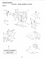
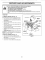
TRACTOR
TO REMOVE
MOWER
(See Fig. 19)
Mower will be easier to remove from the right side of tractor.
o
•
RETAINER
SPRING
Place attachment clutch in "DISENGAGED" position_
Move attachment lift lever forward to lower mower to its
lowest position,
•
Rotf belt off engine pulley,
•
Disconnect clutch rod from clutch lever by removing
retainer spring.
-
Disconnect anti-sway bar from chassis bracket by
removing retainer spring°
-
Disconnect suspension arms from rear deck brackets
by removing retainer springs,
•
Disconnect front links from deck by removing retainer
springs,,
o
Raise lift lever to raise suspension arms. Slide mower
out from under tractor.
RETAENER
SPRINGS
S_DES)
RETAINER
SPRING
IMPORTANT:
IF AN ATTACHMENT OTHER THAN THE
MOWER IS TO BE MOUNTED TO THE TRACTOR,
REMOVE THE FRONT LINKS.
TO INSTALL
MOWER
ANTI-SWAY
(See Fig. 19)
°
Raise attachment lift lever to its highest position.
,
Slide mower under tractor with discharge guard to right
side of tractor.
°
•
Lower' lift lever to its lowest position.
install mower in reverse order of rernoval instructions_
ENGINE
PULLEY
SUSPENSION
BAR
RETAINER
SPRINGS
(BOTH SIDES)
FIG. 19
2O
SERVICE
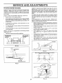
TO LEVEL MOWER
AND ADJUSTMENTS
HOUSING
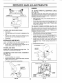
FRONT-TO-BACK ADJUSTMENT (See Figs. 22 and 23)
IMPORTANT: DECK MUST BE LEVEL SIDE-TO-SIDE IF
THE FOLLOWING FRONT-TO-BACK ADJUSTMENT IS
NECESSARY, BE SURE TO ADJUST BOTH FRONT LINKS
EQUALLY SO MOWER WILL STAY LEVEL SIDE-TOSIDE.
To obtain the best cutting results, the mower housing
should be adjusted so that the front is approximately 1/8" to
1/2" lower than the rear when the mower is in its highest
position.
Check adjustment on right side of tractor. Measure distance "D" directly in front and behind the mandrel at bottom
edge of mower housing as shown.
°
Before making any necessary adjustments, check that
both front links are equal in length° Both links should be
approximately 10-3/8".
=
If links are not equal in length, adjust one link to same
length as other linko
°
To lower front of mower loosen nut "E" on both front
links an equal number of turns.
.
When distance "D" is 1/8" to 1/2" lower at front than
rear, tighten nuts "F" against trunnion on both front
links
= To raise front of mower, loosen nut"F" from trunnion on
both front links.. Tighten nut "E" on both front links an
equal number of turns,
When distance "D" is 1/8" to 1/2" lower at front than
rear, tighten nut"F" against trunnion on both front links.
•
Recheck side-to-side adjustment,
Adjust the mower while tractor is parked on level ground or
driveway.
Make sure tires are properly inflated (See
"PRODUCT SPECIFICATIONS" on page 3 of this manual).
if tires are over or underinflated, you will not properly adjust
your mower.
SIDE-TO-SIDE
ADJUSTMENT
(See Figs° 20 and 21)
-
Raise mower to its highest position.
o
At the midpoint of both sides of mower, measure height
from bottom edge of mower to ground. Distance "A" on
both sides of mower should be the same or within 1/4"
of each other..
•
If adjustment is nec6ssary, make adjustment on one
side of mower only,
o
To raise one side of mower, tighten lift link adjustment
nut on that side/
o
To lower one side of mower, loosen lift link adjustment
nut on that side.,
NOTE: Each full turn of adjustment nut will change mower
height about 1/8".
Recheck measurements after adjusting.
BOTTOM EDGE
OF MOWER TO
GROUND
BOTTOM EDGE
OF MOWER TO
GROUND
MANDREL
GROUND LiNE
A
FIG. 20
SUSPENSION
ARM
FIG. 22
BOTH FRONT LINKS MUST BE EQUAL IN LENGTH
0
LIFT LINK
ADJUSTMENT
NUT
FIG. 21
NUT "E"
NUT "1
FRONT LINKS
21
TRUNNION
FIG. 23
SERVICE
A
ADJUSTMENTS
iii,,
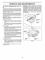
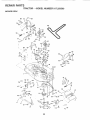
TO
REPLACE
MOWER
BLADE
DRIVE
iJ i
WITH PARKING BRAKE "ENGAGED"
BELT
(See Fig, 24)
The mower blade drive belt may be replaced without tools
Park the tractor on level surface, Engage parking brake,
BELT REMOVAL =
Remove mower from tractor (See "TO REMOVE
MOWER" in this section of this manual)_
o
Work belt off both mandrel pulleys and idler pulfeys_
=
Pull belt away from mower_
NUT "A"
BELT INSTALLATION -
JAM NUT
°
Install new belt in reverse order of removal.
°
Make sure belt is in all pulley grooves and inside all belt
guides,.
Jnstatl mower in reverse order of removal instructions_
o
OPERATING
ARM
FIG. 25
MANDREL
PULLEY
IDLER
PULLEYS
TO REPLACE
(See Fig. 26)
MOTION
DRIVE BELT
Park the tractor on levei surface Engage parking brake,
For assistance, there is a belt installation guide decai on
bottom side of left footrest
°
Remove rnowe_ (See "TO REMOVE MOWER" in this
section of this manual,)
.
Remove upper belt keeper
°
o
Remove belt from stationary idler and cfutching idler.
Pull belt slack toward rear of tractor',. Remove belt
upwards from transaxle pulley by deflecting belt keeperso
o
MANDREL
PULLEY
.
Install new belt by reversing above procedure_
IMPORTANT: MAKE SURE UPPER BELT KEEPER IS
POSITIONED PROPERLY BETWEEN LOCATOR TABS
FIG. 24
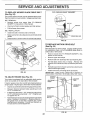
TO ADJUST
BRAKE
Pull belt toward front of tractor and remove downwards
from around engine pulley.
(See Fig. 25)
PULLEY
Your tractor is equipped with an adjustable brake system
which is mounted on the right side of the transaxle,
TABS
IDLER
If tractor requires more than six (6) feet stopping distance
at high speed in highest gear, then brake must be adjusted
°
•
BELT
KEEPER
Depress clutch/brake pedal and engage parking brake.
Measure distance between brake operating arm and
nut "A" on brake rod_
IDLER
If distance is other than ld/2", loosen jam nut and turn
nut "A" until distance becomes 1-1/2'L Retighten jam
nut against nut "A"_
PULLEY
Road test tractor for proper stopping distance as stated
above_ Readjust if necessary. If stopping distance is
still greater than six (6) feet in highest gear, further
maintenance is necessary. Contact your nearest au*
thorized service center/department,.
FiG. 26
22
SERVDCE AND ADJUSTMENTS
TRANSAXLE
SHIFTER
LINKAGE
JUSTMENT (See Figs. 27 and 28)
AND
AD-
TO REMOVE WHEEL
(See Fig, 29)
FOR REPAIRS
The transaxle should be in neutral when the gear shift lever
is in the neutral (N) (lock gate) position The adjustment is
preset at the factory; however, if adjustment is needed,
proceed as follows:
•
Make sure transaxle is in neutral (N).
•
Block up axle securely.
=
Remove axle cover, retaining ring and washers to allow
wheel removal (rear wheel contains a square key- Do
not lose).
.
Repair tire and reassemble,.
o
Loosen two locknuts on tie rod.
•
•
Turn center rod until gearshift lever falls into neutral
lock gate on fender console.
On rear wheels only: align grooves in rear whee_ hub
and axleo Insert square key
°
•
Tighten locknuts securely.
Replace washers and snap retaining ring securely in
axle groove
°
Replace axle cover.
GEARSHIFT
)
,
LEVER
,
_
NEUTRAL
LOCK GATE
NOTE: To seal tire punctures and prevent flat tires due to
slow leaks, tire sealant may be purchased from your iocal
parts deafer_ Tire sealant also prevents tire dry rot and
corrosion.
WASHERS
RETAINING
RING
FIG. 27
AXLE COVER
SQUARE KEY (REAR
WHEEL ONLY)
FIG, 29
TO START ENGINE WITH A WEAK
See Fig. 30)
.............
i i ii
, iiii ii .,11,
CAUTION:
FIG. 28
TO ADJUST
STEERING
WHEEL ALIGNMENT
If steering wheel crossbars are not horizontal (left to right)
when wheels are positioned straightforward, remove steering wheel and reassemble per instructionsin the Assembly
section of this manual.
FRONT WHEEL
TOE-IN/CAMBER
The front wheel toe-in and camber are not adjustable on
your tractor. If damage has occurred to affect the front
wheel toe-in or camber, contact your nearest authorized
service centeddepartment.
II
Lead-acid
BATTERY
II_IIIH
batteries
iiiiii
i1.11
gener-
J
and smoking materials away from batate explosive gases. Keep sparks, flame
teries.
Always wear eye protection
when around batteries.
J
J
|
J
If your battery is too weak to start the engine, it should be
recharged,
if "jumper cables" are used for emergency
starting, follow this procedure:
IMPORTANT:
YOUR TRACTOR IS EQUIPPED WITH A I2
VOLT NEGATIVE
GROUNDED
SYSTEM..
THE OTHER
VEHICLE
MUST ALSO
BE A 12 VOLT
NEGATIVE
GROUNDED
SYSTEM.
DO NOT USE YOUR TRACTOR
BATTERY TO START OTHER VEHICLES°
TO ATTACH JUMPER CABLES °
Connect each end of the RED cable to the POSITIVE
(+) terminal of each battery, taking care not to short
against chassis,.
°
Connect one end of the BLACK cable to the NEGATIVE (-) terminal of fully charged battery.
°
Connect the other end of the BLACK cable to good
CHASSIS GROUND, away from fuel tank and battery
TO REMOVE CABLES, REVERSE ORDER m
BLACK cable first from chassis and then from the fully
charged batter,!.
23 ° RED cable last from both batteries.
SERVICE
AND ADJUSTMENTS
ENGINE
TO ADJUST THROTTLE
(See Fig. 32)
"POSITIVE"
(+}
"NEGATIVE"
(-)
FIG. 30
HEADLIGHT
.
With engine not running, move throttle control lever to
fast (,_) position..
•
Check that swivel is against side of quarter' circle_ if it
is not, loosen cable clamp screw and puIt cable back
until swivel is against quarter circle. Tighten cable
clamp screw securely.
Raise hood.
•
Pull bulb holder out of the hole in the backside of the
grill.
•
Replace bulb in holder and push bulb holder securely
back into the hole in the backside of the grill.
Close hood.,
•
INTERLOCKS
°
•
o
AND RELAYS
Loose or damaged wiring may cause your tractor to run
poorly, stop running, or prevent it from starting..
°
.
Check wiring_ See electrical wiring diagr'am in the
Repair Parts section of this manual.
TO REPLACE
CHOKE
CONTROL
(See Fig. 33)
The choke control has been preset at the factory and
adjustment should not be necessary. Checkadjustment as
described below before loosening cable. If adjustment is
necessary, proceed as follows:
BULB
•
CABLE
The throttle control has been preset at the factory and
adjustment should not be necessary,. Check adjustment as
described below before loosening cable. If adjustment is
necessary, proceed as follows:
TO ADJUST
TO REPLACE
CONTROL
With engine not running, move choke control (located
on dash panel) to fult choke (N) position,.
Remove air cleaner cover, filter and cartridge plate to
expose carburetor choke (see "AIR FILTER" in the
Customer Responsibilities section of this manual).
Choke should be closed., If it is not, loosen casing
clamp screw and move choke cable until choke is
completely closed. Tighten casing clamp screw securely,
Reassemble air cleaner,
CLAMP SCREW
FUSE
QUARTER
Replace with 30 amp automotive-type ptugqn fuse.. The
fuse holder is located behind the dash.,
TO REMOVE HOOD AND GRILL ASSEMBLY
(See Fig. 31)
=
Raise hood.
•
Unsnap headlight wire connector.
o
Stand in front of tractor., Grasp hood at sides, tilt toward
engine and lift off of tractor.
To replace, reverse above procedures.
•
%
SWIVEL
FIG. 32
CHOKE
HOOD
HEADLIGHT
WIRE
CONNECTOR
"""'CHOKE
LEVER
CASING /
CLAMP
SCREW
FIG. 31
24
FIG. 33
SERVmCE AND ADJUST
TO ADJUST
CARBURETOR
ENTS
IMPORTANT:
NEVER TAMPER
WITH THE ENGINE
GOVERNOR,
WHICH IS FACTORY SET FOR PROPER
ENGINE SPEED, OVERSPEEDINGTHE
ENGINE ABOVE
THE FACTORY
HIGH
SPEED
SETTING
CAN BE
DANGEROUS.
IFYOUTHINKTHEENGINE-GOVERNED
HIGH SPEED NEEDS ADJUSTING,
CONTACT
YOUR
NEAREST
AUTHORIZED
SERVlCE
CENTER/
DEPARTMENT,
WHICH HAS PROPER EQUIPMENT AND
EXPERIENCE
TO
MAKE
ANY
NECESSARY
ADJUSTMENTS.
(See Figs. 34 &
35)
The carburetor has been preset at the factory and adjustment should not be necessary. However, minor adjustment may be required to compensate for differences in fuel,
temperature, altitude or loado If the carburetor does need
adjustment, proceed as follows:
In general, turning the mixture screw in (clockwise) decreases the supply of fuel to the engine giving a teaner fuel!
air mixture, Turning the mixture screw out (counterclockwise) increases the supply of fuel to the engine giving a
richer fuel/air mixture°
IDLE SPEED
SCREW
IMPORTANT:
DAMAGE TO THE NEEDLES AND THE
SEATS IN CARBURETOR MAY RESULT IF SCREW IS
TURNED 1N TOO TIGHTI
PRELIMINARY SETTING
o
IDLE MIXTURE
SCREW
Be sure you have a clean air filter, and the throttle
control cable and choke are adjusted properly (see
above).
THROTTLE
LEVER
=
With engine off turn idle mixture screw in (clockwise)
closing it finger tight and then turn out (counterclockwise) 1-1/4 to 1-t/2 turns.
FINAL SETTING
•
°
Start engine and allow to warm for five minutes. Make
final adjustments with engine running and shift/motion
control lever in neutral (N) position.
With throttle control tever in slow (,4_) position, hold
throttle lever against idle speed screw and adjust idle
speed screw to obtain I200 to 1400 RPM,,
-
While still holding throttle lever against idle speed
screw, turn idle mixture screw in (clockwise) until
engine begins to die and then turn out (counterclockwise) until engine runs rough. Turn screw to a point
midway between those two positions
•
Continue to held throttle lever against idle speed screw
and adjust idle speed screw to obtain 900 to 1200 RPM.
Release throttle lever,
FIG. 34
ACCELERATION TESTMove throttle control lever from slow (*_) to fast (,_)
position, If engine hesitates or dies, turn idle mixture
screw out (counterclockwise) I/8 turn_ Repeat test
and continue to adjust, if necess;try, until engine accefcrates smoothty
High speed stop is factory adjusted,
damage may result.,
IDLE MIXTURE
SCREW
LEVER
FIG. 35
Do not adjust -
25
,Jl
ill
ill
......................
STO
ii,,lll ii iiii
i i
AGE
, ,i ill
Immediately prepare your tractor for storage at the end of
the season or if the tractor will not be used for 30 days or
more.
ENGINE
FUEL SYSTEM
IMPORTANT:
IT tS IMPORTANT
TO PREVENT
GUM
DEPOSITS
FROM FORMING
IN ESSENTIAL
FUEL
SYSTEM PARTS SUCH AS CARBURETOR,
FUEL FILTER,
FUEL HOSE, OR TANK DURING
STORAGE.
ALSO,
EXPERIENCE
INDICATES
THAT ALCOHOL
BLENDED
FUELS (CALLED GASOHOL
OR USING ETHANOL
OR
METHANOL) CAN ATTRACT MOISTURE WHICH LEADS
TO SEPARATION
AND FORMATION
OF ACIDS DURING
STORAGE,
ACIDIC GAS CAN DAMAGE
THE FUEL
SYSTEM OF AN ENGINE WHILE IN STORAGE.,
gasoline in the tank inside a building
where
fumesNever
may store
reachthe
an tractor
open flame
CAUTION:
with
or' spark. Allow the engine to cool
before storing in any enclosure°
TRACTOR
Remove mower from tractor for winter storage.. When
mower is to be stored for a period of time, clean it thoroughly, remove all dirt, grease, leaves, etc, Store in a
clean, dry area.
•
Clean entire tractor (See"CLEANING"in the Customer
Responsibilities section of this manual).
o
Inspect and replace belts, if necessary (See belt replacement instructions in the Service and Adjustments
section of this manuai)o
°
Lubricate as shown in the Customer Responsibilities
section of this manual
°
Be sure that all nuts, bolts and screws are securely
fastened,. Inspect moving parts for dama je, breakage
and wear. Replace if necessary.,
°
Touch up all rusted or chipped paint surfaces; sand
lightly before painting,
o
o
Fully charge the battery for storage.
°
After a period of time in storage, battery may require
recharging_
.
To help prevent corrosion and power leakage during
long periods of storage, battery cables should be
disconnected and battery cleaned thoroughly (see "TO
CLEAN BATTERY AND TERMINALS" in the Customer Responsibilities section of this manual).
°
Start the engine and let it run until the fuel lines and
carburetor are empty.
Never use engine or carburetor cleaner products in the
fuel tank or permanent damage may occur.
Use fresh fuel next season_
NOTE: Fue! stabilizer is an acceptable alternative in
minimizing the formation of fuel gum deposits during storage_ Add stabilizer to gasoline in fuel tank or storage
container_ Always follow the mix ratio found on stabilizer
container. Run engine at least 10 minutes after adding
stabilizer to allow the stabilizer to reach the carburetor, Do
not drain the gas tank and carburetor if using fue! stabilizer_
ENGINE
OIL
Drain oil (with engine warm) and replace with clean engine
oil. (See "ENGINE" in the Customer Responsibilities
section of this manual),
BATTERY
•
Drain the fuel tank,
CYLINDERS
After cleaning, leave cables disconnected and place
cables where they cannot come in contact with battery
terminals.
,
°
Remove spark ptug(s)_
Pour' one ounce of oil through spark plug hole(s) into
cylinder(s).
.
Turn ignition key to "START" position for a few seconds
to distribute oil.
•
Replace with new spark plug(s),
OTHER
°
Be sure battery drain tube is securely attached,.
°
Do not store gasoline from one season to another.
o
If battery is removed from tractor for storage, do not
store battery directly on concrete or damp surfaces.
°
Replace your gasoline can if your' can starts to rust,
Rust and/or dirt in your gasoline will cause problems,
°
If possible, store your tractor indoors and cover it to
give protection from dust and dirt°
•
Cover you r tractor with a suitable protective cover that
does not retain moisture. Do not use plastic. Plastic
cannot breathe which allows condensation to form and
will cause your tractor to rust,
IMPORTANT: NEVER COVER TRACTOR WHILE ENGINE
AND EXHAUST AREAS ARE STILL WARM.
26
TROUBLESHOOTING
PROBLEM
Will not start
CAUSE
Engine will not turn over
Engine
start
clicks but will not
Loss of power
Excessive
vibration
CORRECTION
1
Out of fuel.
1
Fill rue? lank
2.
3
4
5.
6
7.
Engine not"CHOKED"properly
Engine flooded
Bad spark plug
D{rty air fi_ter
Dirty fuel fiIter.
Water in fuel
2
3
4
5
6.
7
8
9
Loose or damaged wiring
Carburetor out of adjustment
8
9
See "TO START ENGINE"in Operation section
Wait several minutes before attempting to start
Replace spark plug
Clean/replace airfiiter
Replace fuel filter
Drain fuel tank and carburetor, refilt tank with fresh
gasoline and replace fuel filter
Check all wiring
See "To Adjust Carburetor'' in Service Adjustments
section
10
Hard to start
POmNTS
Engine valves out of adjustment
!0.
Contact an authorized service center/department
1
2
3
4.
5
6
7
Dirty air tilter.
Bad spark plug
Weak or dead battery.
Dirty fuef filter.
Stale or dirty fuel
Loose or damaged wiring
Carburetor out of adjustment
1
2
3
4
5.
6
7
Clean/replace air filter
Replace spark plug
Recharge or replace battery
Replace fuel tilter
Drain rue! tank and refill with fresh gasoline
Check all wiring
See 'To Adjust Carburelor" in Service Adjustments
section.
8
Engine valves out of adjustment.
8
Contact an authorized service center!department
I
2.
3
4
Clutch/brake pedal not depressed
Attachment clutch is engaged
Weakordead
battery
Blown fuse.
5.
6
7
8
9.
Corroded battery'terminafs.
Loose or damaged wiring
Faulty ignition switch.
Faulty solenoid or starter
Faulty operator presence switch(es)
I.
2
3
4
5
6
7
8.
9.
Depress clutch/brake pedal
Disengage attachment clutch
Recharge or replace battery
Replace fuse
Clean battery terminals
Check atl wiring
Check/replace ignilion swilch.
Check/replace solenoid or starter.
Contact an authorized service centeddepartment
1
2
3
4
Weak or dead battery,
Corroded battery' terminals.
Loose or damaged wiring
Faulty solenoid or starter.
t
2
3
4
Recharge or replace battery
Clean battery terminals
Check all wiring
Check/rep{ace solenoid or starter
1
2
3
4
5
6
7
8
9
Cutting too much grassltoo fast
Throttle in "CHOKE" position.
Bui_d-up of grass, teaves and trash under mower
Dirty air filter
Low oil fevettdirty oil.
Fautty spark plug
Dirty fuel filter
Stale or dirty fuel
Water in tuel
1
2.
3
4
5
6.
7
8
9.
Set in "Higher Cut" position/reduce speed
Adjust throttle control
Clean underside of mower housing
Clean/replace air tilter
Check oil Ievelichange oil.
Clean and regap or change spark plug
Replace fuel filter
Drain fuel tank and retill with fresh gasoIine
Drain fuel tank and carburetor, refill tank with fresh
gasoline and replace fuel filter
Connect and tighten spark plug wire.
Clean engine air screen!fins
Clean/replace muffler
Check ail wiring
See "To Adjust Carburetor" in Service Adjustments
section
Contact an autllofized service center/department
10.
!1
12
13
14
Spark plug wire loose
Dirty engine air screen/fins
Dirty/clogged muffler.
Loose or damaged wiring
Carburetor out of adjustment
I0
11
12.
13
14
15
Engine valves out of adjustment
15
1
2
3
Worn. bent or loose blade
Bent blade mandrel
Loose/damaged part(s)
1
2
3
27
Replace blade Tighten blade bott
Replace blade mandrel
Tighlen loose pan(s) Replace damaged parts
=TROUBLESHOOTING
CAUSE
PROBLEM
Engine continues to run
when operator leaves seat
with attachment clutch
POmNTS
CORRECTION
1.
Faulty operator-safety
presence contro{ system
1.
2.
Worn, bent or loose blade
Mower deck not level
3.
4
Buildup of grass, leaves, and trash under mower
Bent blade mandrel.
5
Clogged mower deck vent holes from buitdup of
grass, leaves, and trash around mandre{s
t.
2.
Obstruciion in clutch mechanism
Worn]damagedmower drive heir.
3
4..
Frozen idler pulley
Frozen blade mandrel..
2
3
4
5
6
7
8
Eng{ne speed too stow
Travel speed too fast
Wet grass.
Mower deck not level
Low/uneven tire air pressure.
Worn, bent orloose blade
Buildup of grass, leaves and trash under mower.
Mower drive belt worn
I,
Check wiring, switches and connections,
I! not
corrected, contact an authorized service canted
department,
1
2.
3.
4.
5.
Replace blade Tighten blade boil
Level mower deck.
Clean underside of mower housing
Replace blade mandrel.
Clean around mandrels to open vent holes
1
2
3
4
Remove
Replace
Replace
Replace
1
2
3
4
Place throttte controt in "FAST" position,
Shift to slower speed.
A!low grass to dry before mowing
Level mower deck
engaged
Poor' cut - urteven
................
llllll
ii _ ,J
Mower blades will not
rotate
Poor grass discharge
9
10.
11
BIades {mproperly installed,
Improper blades used,
Clogged mower deck vent ho{es from bui{dup of
grass, leaves, and trash around mandrels.
5.
6
7
8
9
10.
11
obstruction
mower drive belt
idler _,.: !ey
blade _",,_ndrel
Check tires for proper air pressure,
Replace/sharpen btade Tighten blade bolt
Clean underside oi mower housing.
Replace mower drive belt
Reinstall blades sharp edge down.
Replace with blades listed in this manual
Clean around mandrels to open vent holes,
Headlight(s)
not working
(if so equipped)
t
Sw{tch is "OFF"
1
Turn swilch "ON"
2
3
4
5
Butb(s) burned out,
Faulty light switch
Loose or damaged wiring,
Blown fuse.
2.
3
4.
5
Replace bulb(s)
Check/replace light switch
Check wiring and connections,
Replace fuse
Battery will not charge
1
2.
3
4,
Bad battery ceil(s).
Poor cable connections.
Faulty regulator (if so equipped).
Fauity alternator..
t.
2
3
4,
Replace battery
Check/clean all connections.
Replace regulator_
Replace alternator
Engine throttle control not set at "SLOW'*
position for 30 seconds before stopping engine.
t.
Move throttle control to "SLOW" position and aitow
to idle for 30 seconds before stopping engine
Engine "backfires"
when turning engine
"OFF'*
28
TRACTOR
- - MODEL
NUMBER
917.259560
SCHEMATIC
BLACK
REO
BATTERY
I
RED
O Lp
FUSE 30 AMP
AMMETER
(OPTIONAL)
RED
O:
1
STARTER
I
BLACK
WHITE
_G
LI
SEAT SWITCH
(NOT OCCUPIED)
IGNITION
SWITCH
t
l
_ BLAC!_
I
I
I
GROUNDING
CONNECTOR
SPARK PLUG
GAP
(2 PLUGS ON
TWIN CYL, ENGINES)
------O
CHARGING SYSTEM OUTPUT
3 AMP OC @ 3600 RPM
28 VOLTS AC MIN, @ 3600 RFM
(CHARGING SYSTEM DISCONNECTED}
BLUE
I
ORANGE
LIGHTING SYSTEM OUTPUT
5 AMP AC @ 3600 RPM
I
DIODE
14 VOLTS AC MIN
ALTERNATOR
@ 3600 RPM (LIGHTS
OFF)
HEADLIGHTS
BROWN
IGNITION SWITCH
POSITION
CIRCUIT
"MAKE"
oFF G:"+"'M
+L NONE
RUN/LIGHT
B+ L
RUN
B+ L
START
B+ L + S
A +Y
NONE
NONE
NOTE
YOUR TRACTOR IS
EQUIPPED WITH A SPECIAL
ALTERNATOR SYSTEM°
THE LIGHTS ARE NOT
CONNECTED TO THE
NON-REMOVABLE
REMOVABLE
BATTERY, BUT HAVE THEIR
CONNECTIONS
CONNECTIONS
OWN ELECTRICAL SOURCE,.
BECAUSE OF THIS, THE
WIRING INSULATED
CLIPS
BRIGHTNESS OF THE LIGHTS
WILL CHANGE WITH ENGINE
NOTE: IF WIRING INSULATED
SPEED. AT IDLE THE LIGHTS
CLIPS WERE REMOVED
FOR
WILL DIM. AS THE ENGINE IS
SERVICING
OF UNIT, THEY
SPEEDED UP, THE LIGHTS
SHOULD BE REPLACED
TO
WILL BECOME THEIR BRIGHTEST
PROPERLY
SECURE YOUR WIRING
29
/-7-7
REPAIR PARTS
TRACTOR
-- MODEL
NUMBER
917.259560
ELECTRICAL
25
!
I
/
33
/
31
I
9
30
REPAnR PARTS
TRACTOR
KEY
NO.
1
2
3
4
6
7
B
9
10
11
12
16
19
20
21
22
24
25
26
28
29
3O
31
32
33
4O
41
42
43
44
45
52
55
70
-- MODEL
PART
NO.
144926
74760412
STD551025
STD551125
STD541025
7697J
7603J
109596X
145211
150109
145769
153664
STD551125
73350400
147430
4152J
4799J
146148
108824X
145491
12+t305X
140301
124211X
141226
109310X
156442
71110408
131563
145673
73640400
121433X
141940
17490508
140413
NOTE;
NUMBER
917.259560
DESCRIPTION
Battery
Bott, Hex t/4-20 x 3/4
Washer 9/32 x 5/B x 16 Gauge
Washer, Lock 1/4
Nut, Hex 1/4-20
Tube
Tray, Battery
Clamp, Hose
Bolt, Btr Front 1/4-20 x 7-1/2
Holddown Battery Front Mount
Nut, Push Nylon Battery Front t/4
Switch Interlock Push+In
Washer, Lock 1/4
Nut, Hex, Jam t/4-20
Harness, +
BulLight_, Socket (w/4152J)
Light
Cable, Battery
Cable, Battery
Fuse
Cable, Ground
Switch, Seat
Switch, Ignition 4 Position
Nut, Ignition
Cover, Ignitfon Switch
Key, Molded, Craftsman
Harness, Ignition
Bolt Blk Fin Hex I/4-20 UNC x 1/2
Cover, Terminal
Solenoid
Nut Keps Btk Hex 1/4-20 UNC
Ammeter Rectangular 6 Amp
Protection Wire Loop (Hour Meter)
Screw Thdrol 5/16-18 x 1/2
Harness Engine B&SFFec Dual
All component d{mensions given in U,S inches
1 inch = 25,4 mm
31
REPAIR PARTS
TRACTOR
CHASSIS
-- MODEL NUMBER
917.259560
AND ENCLOSURES
28
58
12
53
31
55
57
,14
37
20
23
37
54
37
60
115 1
14
74
32
REPAIR
PARTS
TRACTOR
CHASSIS
- - MODEL
NUMBER
917.259560
AND ENCLOSURES
KEY
NO,
1
2
3
4
5
9
10
1!
12
13
14
17
18
20
23
25
26
28
29
30
31
37
38
39
51
52
53
54
55
57
58
60
64
71
74
I14
115
116
122
123
140
142
143
144
145
147
PART
NO.
159527
140356
17490612
STD551025
155272
150156X011
STD533710
155927
145660
155936
17490608
144983X558
126938X
156437
124028X
19131312
STD541437
145198X558
155217
151287X558
139976
17490508
139886
139887
73800400
19091416
145201
17030814
145202
STD552507
140547
72140606
154798
73680400
STD541437
158112
17490620
191316t4
157301
152927
158418
156095
154966
154207
156524
74760412
DESCRIPTION
Chassis
Drawbar
Screw, Thdo, Roll. 3/8-16 x 3/4 Type TT
Washer 13/32 x 3/4 x 16 Gauge
Bumper HoodlDash
Dash, Silkscreened
Bolt, Carriage 3/8-16 x 1
Panel, Dash, LH
Clip Tinnerman Grille P/L
Panel, Dash, RH
Screw, Thd., Roll 3/8-I6 x 1/2 Type TT
Hood Assembly
Bumber Hood
Plate Mtg Battery Fuel Tank
Bushing, Snap, Nylon, Fuel Line
Washer 13/32 x 13/16 x 12 Gauge
Locknut, Hex, with insert 3/8-16 UNC
Grille, W/Clips MS-558
Lens, Grille
Fender/Footrest
Bracket, Fender/Support
Screw, Thdrok 5/16-18 x 1/2 TYT
Pivot Bracket Assembly, LH, Mower, Rear
Pivot Bracket Assembly, RH, Mower, Rear
Nut Lock W/Insert 1/4 - 20 UNC
Washer 9132 X 7/8 X 16 Ga.
Bracket Grille Pickoff LH
Screw, Hex Head, Spiderlock #8 x 7t8 AB
Bracket Grille Pickoff RH
Bolt FinHex 1/4 -20 UNC X75
Air Duct P/L 18HP B&S Opp Twin
Bolt Rdhd Sqnk 3/8-16 UNC x 3/4
Dash Lower STLT
NtJt Crownlock !/4-20 UNC
Nut Crownlock 3/8-16 UNC
Keeper Belt Rear LH
Screw Thdrot 3/8-16 x 1-1/4
Washer 13/32 x 1 x 14 Ga.
Bracket Shift STLT
Screw
Bracket Suspension Front
Plate Reinforcement STLT
Backrest Swaybar Chassis
Bracket Footrest STLT
Rod Pivot ChassistHood
Bolt Hex Hd 1/4-20 UNC x 3/4
NOTE: All component dimensions given in US
1 inch = 25,4 mm
33
inches
REPAIR PARTS
TRACTOR - - MODEL NUMBER 917.259560
DRIVE
57
121
2i
)
118
37
75
34
REPAIR PARTS
TRACTOR
- - MODEL
NUMBER
917.259560
DRIVE
KEY
NO.
2
3
4
5
6
8
10
11
13
14
15
18
19
21
22
24
25
26
27
28
29
30
31
32
34
35
36
37
38
39
40
41
42
47
48
49
50
5I
52
PART
NO.
146682
123666X
12000028
121520X
17490512
154792
STD561210
105701X
74550412
STD551125
74490544
STD523710
STD541437
106933X
130804
STD541237
!06888X
STD551037
STD56t210
145204
124236X
130807
127275X
STD523!07
155071
120183X
STD551062
STD571810
123674X
STD523727
4470J
154777
19131312
127783
154604
123205X
STD523715
STD541437
STD541431
DESCRIPTION
Transaxle (See Breakdown)
Peerless 930-057A
Spring, Return, Brake
Pulley, Transaxle
Ring, Retainer
Strap, Torque
Screw, Thd, Roll. 5/16-18 x 3/4
Rod Shifter Fender STLT
Pin, Cotter .
Washe'r, Shift I_tate
Bolt 1/4-28 UNF W/Patch Grade 8
Washer
Bolt, Hex FIghd 5/16-18 Grade 5
Bolt Fin Hex 3/8-16 UNC x 1 Gr 5
Nut
Knob
Rod, Brake
Nut
Spring, Brake Rod
Washer
Pin
Rod, Parking Brake
Cap, Parking Brake, Red
Bracket, Transaxle
Keeper, Belt, L.H
Bolt
Shaft Assembly, Foot Pedal
Bearing, Nylon
Washer
Roti Pin
Pulley, Idler, Flat
Bolt
Spacer, Split 395 x .59
Keeper, Belt, Idler Foo!-Proof
Washer 13/32 x 13/16 x 12 Gauge
Pulley, Idler, V-Groove, Plastic
Bellcrank Assembly
Retainer, Belt
Bolt
Nut Crown Lock 3/8-16 UNC
Nut Crown Lock 5/!6-18 UNC
KEY
NO.
PART
NO.
53
55
56
57
58
59
61
62
63
64
105710X
105709X
STD523712
130801
127274X
140312
17490612
8883R
140186
71170764
65
66
70
72
74
75
76
77
78
79
80
81
82
83
84
85
86
87
88
89
90
96
112
113
116
118
121
STD551143
154778
134683
19132012
t37057
121749X
STD581075
123583X
121748X
2228M
145090
156049
123782X
19171216
145643
!50360
71208
19212016
12000008
154886
124346X
4497H
19091210
127285X
72110610
154774
154419
NOTE:
35
DESCRIPTION
Link, Clutch
Spring, Clutch Return
Bolt Fin Hex 3/8-16 x 1-1/4
V-Belt, Ground Drive
Keeper, Belt, R H
Keeper, Belt, Center Span
Screw, Thd, Roll. 3/8-16 x 3/4
Cover, Pedal
Pulley, Engine
Bolt, Hex Head, Fin.
7/16-20 x 4 Grade 5
Washer
Keeper, Belt, Engine, Foot-Proof
Guide, Belt RH Engine
Washer 13/32 x 1_1/4 x 12 Gauge
Spacer, Axle
Washer 25/32 x 1-1/4 x 16 Gauge
E-Ring
Key, Square 2..0 x .1845L1865
Washer 25/32 x i-5/8 x 16 Gauge
Key Woodruff #9 3/16 x 3/4
Arm, Shift
Shaft Assembly
Spring, Torsion
Washer 17/32 x 3/4 x 16 Gauge
Tie Rod
Nut, Nylock
Bushing, Pivot
Washer
E-Ring
Console, Shift, STLT
Nut, Self-Threading, Washer Hd 1/4
Retainer Spring 1" Zinc Cad
Washer 9/32 x 3/4 x t0 Gauge
Strap Torque LT
Bolt Rdhd Sqneck 3/8-16 x 1.25
Spacer Belfcrank
Nyliner Clutching STL
All component dimensions given in U.& inches
1 inch = 25, 4 mm
REPAIR PARTS
TRACTOR
STEERING
- - MODEL NUMBER 917.259560
ASSEMBLY
+++
:._:_.
•_
;
....
~+
+_+_.=.j
39
.
4t
Cb:
/
40
25
\
+J
68
"/+
36
REPAIR PARTS
TRACTOR
STEERING
-- MODEL
NUMBER
9'17.259560
ASSEMBLY
KEY
NO.
PART
NO.
1
2
3
4
5
6
7
8
9
10
11
13
15
17
t8
19
20
22
139768
154427
156483
157473
6266H
121748X
19272016
12000029
3366R
156438
STD551137
154779
73901000
156546
57079
124035X
126684X
71100410
23
25
26
27
28
29
30
32
36
37
38
39
40
4t
42
43
44
46
47
51
53
54
62
63
65
66
67
68
69
70
127501
154406
126847X
136874
19131416
17490612
STD561210
130465
155099
152927
139769
19133808
STD541537
100711L
145054
121749X
153720
121232X
6855M
STD541431
73680600
74780520
156594
STD523710
154780
154404
74781044
154429
160367
74780636
DESCRIPTION
Steering Wheel
Axle Assembly STMP Dropped STL
Spindle Assembly, L.H.
Spindle Assembly, R..H.
Bearing, Race, Thrust, Hardened
Washer 25/32 x 1-5/8 x 16 Gauge
Washer 27/32 x 1-1/4 x 16 Gauge
Ring, Klip
Bearing, Steering Column
Draglink Extended Stamped
Washer, Lock
Bearing Axle STLT/GT
Nut, Lock, Flange 5/8-11 UNC
Shaft Assembly, Steering
Washer, Thrust 515 x _750 x .033
Support, Shaft
Washer, Shim 1/4 x 5/8 x .062
Screw, Hex Socket Head
1/4-20 x 5/8
Pittman Shaft Assembly
Bracket, Steering
Bushing, Link, Drag
Gear, Sector
Washer 13t32 x 7/8 x 16 Gauge
Screw, Thd., Rolto 3f8-16 x 3f4
Pin
Rod, Tie
Bushing, Steering
Screw
Insert, Steering Wheel
Washer 13/32 x 2-3/8 x 8 Gauge
Gripco Nut
Adaptor, Steering Wheel
Boot, Steering Shaft
Washer 25/32 x 1-1/4 x 16 Gauge
Extension Shaft Steering LR.LT
Cap, Spindle
Fitting, Grease
Nut Lock Hex w/Ins.. 5/I6-18 UNC
Nut, Crownlock 3/8-16 UNC
Bolt Fin Hex 5/16-18 UNC x I-1/4
Kit Steering Asm Service
Bolt, Fin Hex 3/8-16 UNC x 1 Gr 5
Spacer Axle
Bearing Arm Pittman
Bolt, Fin Hex 5/8-1 t UNC x 2-3/4
Axle, Brace
Spacer, Brace, Axle
Bolt, Fin, Hex 3/8-16 UNC x 2-1/4
NOTE: All component dimensions given in U.S. inches
1inch=254mm
37
REPAUR PARTS
TRACTOR
-- MODEL NUMBER
917.259560
SEAT ASSEMBLY
8,....,...=_
10
5
23
12
KEY
NO.
PART
NOo
1
2
3
4
5
6
7
8
9
10
12
140123
140551
747606 t 6
19131610
145006
STD541437
124181X
17490616
19131614
155925
121246 X
DESCRIPTION
KEY
NO.
PART
NO.
Seat
Bracket Pnt Pivot Seat (blk)
Bolt Fin Hex 3/846 UNC x 1
Washer Fiat 13/32 x 1 x !0 Ga
Clip Push-In
Nut Lock Hex W!Ins 3/8 -16 UNC
Spring Seat Cprsn 2 250 Blk Zi
Screw 3/8-16xl
Washer 13/32 x 1 x 14 Ga
Pan Pnt Seat (blk)
Bracket Pnt Mounting Switch
13
14
15
16
17
21
22
23
24
25
26
121248X
72050411
134300
121250X
123976X
153236
STD541431
74780814
19171912
127018X
STD551150
DESCRIPTION
Bushing Snap Btk Nyl 50 Id
Bolt Rdhd Sht Nk 1/4-20x!-3/8
Spacer' Split 28 X 96 Zinc
Spring Cprsn 1 27 BIk Pnt
Nut Lock 1/4 Lge Fig Gr 5 Zinc
Bolt Shoufder 5/16-18 Unc
Nut Lock Hex W/Ins 5/16-18
Bolt Fin Hex 1/2-13 X 7/8 Gr 5
Washer 17/32 X I-3/16 X 12 Ga
Bolt Shoulder 5/16-18 X 62
Washer Lock Hvy Hlcl Spr 1/2
NOTE: All component dimensions given in U,S, inches
1 inch = 25_4 mm
38
REPAIR PARTS
"
TRACTOR
-- MODEL NUMBER
917.259560
DECALS
6 1
10
7
7
17
\
22
/
19
14
13
14
2
15
KEY
NO.
1
2
3
4
6
7
9
10
11
13
PART
NO.
156439
273503
151299
151300
133644
150927
146709
15O333
156368
146046
DESCRIPTION
KEY
NO,
Decal
Decal,
Decal
Decal
Decat
Decal
Decal
Decal
Decal
Decal
!4
15
17
19
20
22
---- -
Fender Danger Sears
Engine 19o5 HP Turbo
Hood Rh Craftsman
Hood Lh Craftsman
Maint Customer Sears Dom
Panel Side B&S
Fender Craftsman Gold
Cap CNSMR Help Line SRS
Fender STLT Oper tnst E/S
V-belt Dr Sch
PART
NO.
147139
160396
158215
138047
156787
149516
138311
154515
154516
159806
159807
KEY
NO.
1
2
3
4
4,10
!,9
tl
PART
NO.
59192
65139
106222X
59904
5
6
7
8
9
10
106732X427
278H
9040H
106108X427
122082X
7152J
11
--
104757X
144334
NOTE:
39
DESCRIPTION
Decal Chassis 42"
Decal Mower Drive Schematic
Decal Insert, Hood
Decal Battery Diehard Sears
Decal Deck Mower EZ3 Mulching
Decal Battery
Decal Lift Handle
Pad Footrest Lh STLT
Pad Footrest Rh STLT
Manual, Owner's (English)
Manual, Owner's (Spanish)
DESCRIPTION
Vafve Cap, Tire
Stem, Valve
Tire, Front
Tube, Front Tire
(Not Provided, Service Item Only)
Rim, Front
Fitting, Grease (Front Wheel Onfy)
Bearing, Flange (Front Wheel Only)
Rim, Rear
Tire, Rear
Tube, Rear Tire
(Not Provided, Service Item Onty)
Cap, Axle
Seafant, Tire (10 oz Tube)
All component dimensions given in U, S, inches
1 inch = 25,4 mm
.. _,AOOF-.tNU_IB_._
_EpAIF_ PA_J_BAcTO_
39
_9
_5
_0
REPAIR PARTS
TRACTOR
- - MODEL
NUMBER
917.259560
ENGINE
KEY
NO.
1
2
3
PART
NO.
151273
17720410
4
5
6
7
8
10
11
12
t3
14
15
16
17
23
25
26
27
29
31
32
33
34
35
37
38
149723
144069
144068
_38129
150176
145552
STD551125
STD522507
272250
13280336
13200300
STD551237
17490624
156123
145996
73920600
152927
137180
157103
155971
123487X
106082X
17490512
8543R
.......
39
40
41
81
109227X
3645J
139277
128861
DESCRIPTION
Control Throt Paddle 32 22
Screw Hex Thd Cut 1/4-20x5/8 T
Engine (See Breakdown) Briggs
Model No, 42E707-1631-01
Muffler Exhaust
Exhaust Asm, Left
Exhaust Asm, Right
Clamp Tube Double Engine
Bolt 5/16 - 18 UNC X 3/4 W/Sems
Heat Shield Lt
Washer Lock Hvy. Helical 1/4
Boft Fin Hex 1/4-20 x 3/4
Gasket Muffler
Nipple Pipe 4-1/2"
Elbow Std 90 Degree 3/8-18 Npt
Washer Lock Ext Tooth 3/8
Screw Thdrot 3/8-16x1-1/2 Tytt
Shield Browning
Control Choke
Nut Keps 3/8-24 Unf
Screw TT #10-32 x 5 x 3/8 Flange
Arrestor Spark
Tank Fuel 3 50 Rear
Cap Fuel Guage STLT
Clamp Hose Blk
Spacer Pad
Screw Thdrol 5/16-18 x 3/4 TYT
Line Fuel
Plug Oil Drain (Order From Engine
Manufacturer)
Pad Idler 1.75 x .75 x .06
Bushing
Stem Tank Fuel
Nut, Flange t/4-20 Starter Nut
NOTE: All component dimensions given in U.S. inches
1 inch = 25.4 mm
41
REPAIR PARTS
TRACTOR
MOWER
- - MODEL
NUMBER
917.259560
LIFT
"_
/ 25 2423
7
8
5
49
,
/
!
30
3
13
50
\
26
4
6
6
5
12
13
I
19
I
20
20
161718
19
15
32
42
REPAnR PARTS
TRACTOR
MOWER
- - MODEL
NUMBER
917.259560
LIFT
KEY
NO,
PART
NO.
1
2
3
4
5
6
7
8
11
12
13
15
16
17
18
19
20
23
24
25
26
27
28
29
30
31
32
49
50
159460
159471
105767X
12000002
19211621
120183X
125631X
122365X
139865
139866
STD624008
127218
73350800
130171
73800800
139868
STD624008
110807X
19131016
2876H
76020308
t26971X
73350600
138057
150233
140302
73540600
145212
!10452X
DESCRIPTION
WireAssyo, Inner, with Plunger
ShaftAsm Lift
Pin Groove
E Ring #5133-62
Washer 21/32 x 1 x 21 Ga
Bearing Nylon
Grip Handle Fluted
Button Plunger Read
Link Lift Lh Fixed Length
Link Lift Rh Fixed Length
Retainer Spring
Link Front
Nut Jam Hex 1/2-13 Unc
Trunnion BlkZinc
Nut Lock W/Wsh 1/2-13 Uric
Arm Suspension Rear
Retainer Spring
Nut Spring
Washer 13/32 x 5/8 x 16 G&
Spring 2-1/8"
Pin cotter 3/32 x 1/2
Rod Adj. Lift
Nut Hex Jam 3/8-t6
Knob Inf. 3/8q6
Trunnion lnfin. Height
Bearing, Pivot, Lift, Special
Nut, Crownlock 3/8-24
Nut Ftange Lock
Nut Push
NOTE: All component dimensions given in US
1 inch = 2&4 mm
43
inches
REPAaR PARTS
TRACTOR -- MODEL NUMBER
MOWER
917.259560
DECK
,_'_ 40
105
34
102
33
32
106
21
113 111
22
23
24
\
25
2
16
27
t8
18
21
44
REPAUR PARTS
TRACTOR
MOWER
- - MODEL
NUMBER
917.259560
DECK
KEY
NO.
PART
NO.
1
2
3
4
5
6
8
9
I0
11
12
13
144393
STD533107
138017
138440
STD624008
130832
850857
STD551137
140296
134149
129895
137645
14
15
16
17
18
19
20
21
22
23
24
25
26
27
28
29
30
31
32
33
34
35
36
37
40
41
43
44
45
46
48
49
50
51
52
53
128774
I10485X
140329
72110610
72140505
132827
136888
STD541431
134753
131267
t05304X
123713X
110452X
130968
19111016
131491
157722
129963
153535
137266
STD533717
133835
131494
19131316
STD541437
133551
140083
140088
STD624003
137729
133944
155066
131340
STD5414!0
139888
131845X900
KEY
NO.
DESCRIPTION
Mower Housing
Bolt
Bracket Assembly,Sway Bar, Front
Bracket Assembly, Sway Bar
Retainer Spring
Arm, Suspension, Rear
Bolt, Hex 3/8-24 x 125 Grade 8
Washer, Lock
Washer, Hardened
Blade; Mulching
•Bearing, Ball
Shaft Assembly, Mandrel, Vented
(Includes Key Number 6)
Housing, Mandrel, Vented
Bearing, Ball, Mandrel
Stripper, Vented Mower Deck
Bolt, Carriage 3/8-16 x 1-1/4
Bolt, Carriage 5/16-18 x 5/8
Bolt, Shoulder
Baffle, Vortex
Nut Crownlock 5/16-18 UNC
Stiffener Bracket
Bracket, Deflector
Cap, Sleeve
Spring, Torsion, Deflector
Nut, Push
Shield, Deflector
Washer 11/32 x 5/8 x 16 Gauge
Rod, Hinge
Screw Thdrol Washer Head
Washer, Spacer
Pulley, Mandrel
Nut, Toplock, Flanged
Bolt
Fastner, Christmas Tree
Pulley, Idler, Flat
Washer 13/32 x !3/16 x 16 Gauge
Nut Crownlock 3/8-16 UNC
Rod, Pivot, with Nibs
Rod, Clutch, Secondary, with Nibs
Guard, Mandrel, L.H.
Retainer
Screw, Thd. Roll 1/4-20 x 5/8
Washer, Hardened
Roller Assembly, Cam Follower
Bolt, Shoulder #10-24 Grade 5
Locknut
Bolt, Shoulder 5/16-18 UNC
Arm Assembly, Pad, Brake
54
55
56
58
59
67
68
71
72
73
74
75
76
77
78
79
80
81
82
83
84
85
92
101
102
103
104
105
106
111
112
113
114
115
116
117
1t8
119
121
128
129
t30
131
132
""
"
PART
NO.
133943
155046
122052X
14O086
141043
149846
144200
142427
131870
127847
I2t748X
12000029
128903
127845
154809
127498
153701
73350600
142028
120958X
156084
72140618
STD541437
136420
71161010
19061216
STD55t110
130758
2029J
155197
155198
17490512
73510500
72110504
137644
133957
73930600
19121414
143723
153390
19131312
STD523710
STD533710
19132293
130794
145411
NOTE:
45
DESCRIPTION
Washer, Hardened
Arm, Idler
Spacer, Retainer
Spring, Torsion Brakes
Guard, TUV Idler
Knob Custom Oval
V-Belt
Rod, Clutch, Primary, with Nibs
Spring, Return
Arm, Clutch, Secondary
Washer 25/32 x 1-5/8 x 16 Gauge
Ring, Klip
Bolt, Shoulder 3/8-16 UNC x 1.44
Keeper, Spring
Lever Asm Clutch Pri Plm STLT
Bushing, Large, Brass
Spring, Mower Clutch
Nut, Hex Jam 3/8-16 Unc
Trunnion, Adj..
Washer, Sintered
Keeper Belt idler
Bolt RDHD Sq 3/8q6 UNC x 2-t/4
Nut
Mulcher Cover
Screw
Washer #10
Washer, Lock
Latch Assembly, Bagger
Nut, Weld
Bracket, Gauge, Wheel LoHo
Bracket, Gauge, Wheel RH
Screw Thdrol 5/16-18 x 3/4
Nut, Hex, Keps 5/16q8 UNC
Bolt, Carriage 5/t6 UNC x t/2
Bolt, Shoulder
Wheel, Gauge
Nut, Centerlock 3/8-I6
Washer 3/8 x 7/8 x 14 Gauge
Bracket
Washer Felt
Washer 13/32 x 13/16 x 12 Ga.
Bolt, Fin Hex 3/8-16 UNC x 1 Gr. 5
Bolt, RDHD SQNK 3/8-16 UNC x 1
Washer 13/32 x 1-3/8 x 4 Ga.
Mandrel Assembly (Includes Key
Numbers 8-10, 12-15, 31 and 32)
Mower Deck, Complete (Standard
All component dimensions given in U.S inches
1 inch = 25.4 mm
REPAIR PARTS
TRACTOR - - MODEL NUMBER 917.259560
PEERLESS
J
TRANSAXLE
- MODEL NUMBER
23
35
930-057A
77
29
47
/
13
t5
90
/
79
43
150
9OO
42
46
REPAIR
PARTS
TRACTOR
PEERLESS
REF PART
NO. NO.
1
2
3
4
5
6
7
8
8A
9
10
11
12
13
14
15
17
18
20
21
22
23
25
772108A
780086A
770102A
776260A
776219B
778139
778136
792136A
792047
784352
784355
778229
778!13A
778221
778068
778260
786139
786102
792077
792078
792079
788061
792073
26
792f25
27
28
29
30
31
32
33
34
35
36
37
38
39
40
4!
42
792035
788040
780072
780108
780001
792001
788095
780105A
780118A
790003
790007
799021
786026
792076A
790079
792073
42A 792085A
TRANSAXLE
- MODEL
- - MODEL
NUMBER
NUMBER
917.259560
930-057A
REF PART
NO. NO,
DESCRIPTION
Cover, Transaxte
Bearing, Needle
Case, Transaxle
Shaft, Counter
Shaft and Pinion Assembly, Output
Gear, Output, 35 Teeth
Gear, Spur, 15 Teeth, Steel
Key_ Shift
,Key, WoodrUff
Collar, Shifter
Rod and Fork Assembly, Shift
Gear, Bevel, 42Teeth
Bevel Pinion, Input
Gear, Bevel, 16 Teeth
Gear, Bevel Pinion
Gear, Ring
Pin, Drive
Spacer, Neutral
Ball, Steel 5/16" diameter
Set Screw 3/8-16 x 3/8
Spring
Ring, Seal
Screw, Flanged Hex Head, Thread
Forming 1/4-20 x 1-1/4
Ring, Retainer
(4 Required, Package of 2)
Ring, Retainer
Ring, Retainer
Washer, Thrust
Washer, Thrust
Washer
"O" Ring
Sea], Square Cut
Bushing, Flanged
Bushing, Flanged
Disk, Brake
Plate, Brake Pad
Pad, Brake (Package of 2)
Pin, Dowel
Washer, Flat
Lever, Brake
Screw, Flanged Hex Head, Thread
Forming 1/4-20 x 1-1/4
Screw 1/4-20 x 2-1/4
43
44
45
46
47
48
49
50
51
52
53
54
56
57
58
59
60
61
65
66
67
68
69
70
71
72
72A
76
77
79
81
82
83
90
103
104
150
900
792075
790025
786066
786086
774690
774691
778215
778125
778124A
778123A
778122A
778273
778230
776151
778!26A
778127A
778!28A
778163
780109
776135
776315A
786116A
780051
786118
788069
792165
788091
780090
788078A
792144
786081
786082
786123
788067B
792166
792167
788093
794602
DESCRIPTION
Locknut 5t16_24
Holder, Brake Psd
Spacer
Bracket, Brake Lever
Axle 1 t-5/16" long
Axle I6-1/2" long
Gear S3ur, 37 Teeth, Steel (1,,)
Gear S 3ur, 35 Teeth (2°°)
Gear S 3ur, 30 Teeth (3,,)
Gear S3ur, 25 Teeth (4,,)
Gear S 3ur, 22 Teeth (5,,)
Gear S :_ur, 19 Teeth, Steel (6,,)
Gear S3ur, 12 Teeth, Steel (1,,)
Gear S_ur, 15 Teeth (2.,)
Gear S 3ur, 20 Teeth (3_)
Gear S 3ur, 25 Teeth (4,,)
Gear, S 3ur, 28 Teeth (5_)
Gear S 3ur, 31 Teeth (6,,)
Washer Thrust
Shaft, In )ut
Shaft, Brake, 4 Keyed
Plug
Washer, Thrust
Spacer
Square Cut Ring
Plug, Threaded 9/16-18
"O" Ring
Washer, Thrust
Ring, Retaining, Inverted
(Package of 2)
Spring, Brake
Chain, Roller
(Number 41 Chain, 24 Links)
Sprocket, 9 Teeth (Reverse)
Sprocket, 18 Teeth (Reverse)
Grease, Bentonite, 32 Ounce Bottle
Screw t/4-20 x 2
Locknut 1/4-20
Gasket Eliminator (Loctite #515)
Replacement Transaxle
NOTE: All component dimensions given in U.S. inches
I inch = 2&4 mm
Parts must be ordered from Tecumseh Products Co.
47
REPARR PARTS
TRACTOR
BRIGGS
& STRATTON
="
ENGINE
615
552A
-- MODEL
- MODEL
NUMBER
NUMBER
917.259560
42E707, TYPE
868
40
42 _'_
41
615 q_
NUMBER
1631-01
35
819
34
36
33
220 _
23o
12
534
?
642
_'
165
643
32
535
523
842
445
235
161
601
525
524
0
601
537
48
REPAIR PARTS
TRACTOR
BRIGGS
& STRATTON
ENGINE
-- MODEL
- MODEL
NUMBER
NUMBER
9'17.259560
42E707,
TYPE
NUMBER
1631-0'1
51
1358
GASKET
1861 PUMP
SET !
REPAIR
1121
CARBURETOR
51A
KIT 1
51
52
KIT
205
95
103
104
0
634
232
_119
_
202
257
394
859
93
392
52
54
434
117
356
334
851
468
332
Q
75
188
1006
337
635
726
.......
i,
49
383
REPAIR PARTS
TRACTOR
BRIGGS
& STRATTON
- - MODEL
NUMBER
ENGINE - MODEL NUMBER
917.259560
42E707, TYPE NUMBER
1631-01
801
783
802
311
803
653
544
201
209
209A
414 207
307
50
REPAIR
PARTS
TRACTOR
BRIGGS
& STRATTON
ENGINE
- - MODEL
NUMBER
- MODEL NUMBER
42E707,
917.259560
TYPE NUMBER
'1631-01
22
881
8
..........................
7A
1'i058 OWNER'SMANUALI
i 10'i'9'LABEL KITI
_r REQUIRES SPECIAL TOOLS
TO INSTALL. SEE REPAIR
INSTRUCTION MANUAL.
305
3O5
304
308A
307
3O8
306
3O5
307
306A
51
REPAIR PARTS
TRACTOR
BRIGGS & STRATTON
KEY PART
NOo NO.
1
497074
2
3
4
5
5A
7
7A
8
8A
399265
391086
493304
493457
493458
271867
271868
495754
222892
9
10
IOA
11
12
27803
94382
94830
280225
273208
271188
271189
13 94565
15 94239
16 394028
94196
20 291675
22 94724
23 491180
24 222698
25 498584
498585
498586
498587
26 394959
394960
394961
394962
27 263129
28 498319
391286
29 394306
397158
32 94671
33 390420
34 261528
35 65906
36 26828
40 221596
41 292260
42 494553
45 261368
46 213520
50 213290
51 271412
51A 281411
52 270884
53 93970
- - MODEL
NUMBER
ENGINE - MODEL NUMBER
917.259560
42E707,
TYPE NUMBER
KEY PART
NO. NO.
DESCRIPTION
Cylinder Assembly
54
75
78
90
91
Bushing
* Seat, Oil
Sump, Engine
Head, Cylinder#1
Head, Cylinder #2
* Gasket, Cylinder Head #1
* Gasket, Cylinder Head #2
Breather Assembly #1
Cover, Breather Cylinder'#2
(Used Only on Key#572,
Air Baffle with Holes for Mounting)
* Gasket, Breather
Screw, Sems
Screw, Sems
Tube, Breather
* Gasket, Crankcase, _015" Thick
* Gasket, Crankcase, .005" Thick
* Gasket, Crankcase, 009" Thick
Screw, Cylinder Head
Plug, Oil Drain
Crankshaft
Timing Gear Key
* Seal, Oil
Screw, Serns
Flywheel
Key, Flywheel
Piston Assembly, Standard Size
Piston Assembly, .010" Oversize
Piston Assembly, ._020"Oversize
Piston Assembly, .030" Oversize
Ring Set, Standard Size
Ring Set, .010" Oversize
Ring Set, °020" Oversize
Ring Set, .030" Oversize
Lock, Piston Pin
Pin, Piston, Standard Size
Pin, Piston, .005" Oversize
Rod, Connecting, Standard Size
Rod, Connecting, .020" Undersize
Screw, Connecting Rod
Valve, Exhaust
Valve, Intake
Spring, Valve, Intake
Spring, Valve, Exhaust
Retainer, Valve, Intake
Retainer, Valve, Exhaust
Keeper', Valve
Tappet, Valve
Gear, Cam
Manifold, Intake
.... Gasket, Carburetor Mounting
Spacer, Carburetor'
* Gasket, Intake Manifold Mounting
Screw, Hex Head,
Carburetor to Manifold
93
94
95
96
97
98
99
102
103
104
105
107
108
109
116
117
93208
222511
95039
495181
495035
231209
491538
93499
221939
392672
91920
26157
271607
298514
231435
394683
491543
223534
392673
280474
231338
231333
119 94152
121 491539
223472
127
496599
161
165 94289
299146
187
188 94627
201 262683
202 262684
203 280997
93971
205
94298
206
262337
207
262352
209
209A 261563
394348
219
219A 393415
222773
220
491282
222
94297
224
*
**
***
****
1631-01
DESCRIPTION
Screw, Phillips
Washer, Spring
Screw, Hex
Carburetor
Body Assembly, Upper
Bushing, Throttle Shaft
Valve, idle Adjust
Screw, Sems
Valve, Throttle
Shaft, Throttle
Screw, FiUister Head
Spring, Throttle Adjust
Gasket, Carburetor Body
Float, Carburetor
Pin, Float Hinge
Valve, Needle
Body Assembly, Lower
Valve, Choke
Shaft, Choke
O-Ring
Jet, Needle Valve, Fixed
Jet, Needle Valve, Fixed,
High Altitude
Screw, Hex Head
Carburetor Kit
Plug, Welch
Base, Air Cleaner
Nut, Wing
Line, Fuel, 28" Long (Cut to Suit)
Screw
Link
Link
Crank, Bell
Screw, Hex Head
Nut
Spring, ControL, Rod
Spring, Governor
Spring, Governor Idle
Gear, Governor
Oil Slinger
Washer, Thrust
Bracket, Control
Screw, Torx®
Included in Gasket Set (495868)
Included in Carburetor Kit (491539)
Included in Carburetor Kit (49! 539),
and Pump Repair Kit (393397)
Included in Gasket Set (495868),
and Carburetor Kit (491539)
NOTE: All component dimensions given in U.S. inches
1 inch = 25.4 mrn
52
REPADR PARTS
TRACTOR
BRIGGS
& STRATTON
KEY PART
NO. NO,
227 491297
229 62199
230 223882
235 224995
240 394358
244 230318
257 93897
258 94623
259 223890
265 221535
267 94906
284 94674
284A 94882
304
495469
305
94786
306
222846
306A 223734
307
94930
308
224774
308A 224775
309 497596
310 94003
311 497608
332 230674
333 394891
334 94731
337 802592
356 494705
358 491856
363 19203
383 89838
387 280197
392 261395
394 270988
414 220680
422 222875
432 221377
434 223688
435 93829
445 394019
468 497908
474 393474
482 93621
510 497606
523 494947
524 271157
525 495348
528 393815
534 94823
535 272490
537 27141t
544 497603
552 262332
552A 262331
ENGINE
- - MODEL
NUMBER
- MODEL NUMBER
917.259560
42E707, TYPE NUMBER
KEY PART
NO. NO,
DESCRIPTION
Lever Assembly, Governor
Washer
Washer, Governor Crank, Inside
Shield, Fuel Spray
Filter, Fuel
Connector, Fuel Line
Screw, Seres
Screw, Seres
Bracket, Cable
Clamp, Casing
.Screw, Senis
Screw, Hex Head
Screw, Hex Head
Housing, Blower, Red
Screw, Seres
Shield, Cylinder
Shield, Cylinder
Screw, Self-Tapping
Cover, Air Guide
Cover, Air Guide
Motor, Starter
Bott, Thru
Brush Set
Nut, Hex
Armature, Magneto
Screw, Seres
Plug, Spark
Wire, Stop
Gasket Set
Flywheel Puller
Wrench, Spark Plug
Body, Pump
**" Spring, Diaphragm
*** Diaphragm, Carburetor
Washer
Bracket, Oil Fill
***Cap, Spring
Cover, Diaphragm
Screw, Diaphragm Cover
Filter, Air
Screen, Rotating
Alternator
Screw,
Drive, Starter
Cap, Oil Fill
* Seal, Fill Tube
Tube, Oil Fill (Includes Seals
Hose, Vacuum
Screw, Air Cleaner
Filter, Air
.... Gasket, Air Cleaner
Armature, Starter
Lower Bushing, Governor
Upper Bushing, Governor
556 93585
562 93853
567 9481t
569
572
573
592
601
615
6t5A
616
634
634A
635
642
643
653
726
272645
224816
491304
92278
93053
94296
263080
491530
271013
491287
66538
225008
496700
93585
391362
741
783
80I
802
803
819
842
847
851
858
859
860
861
868
869
870
871
262989
280104
394860
497607
497604
94675
270920
495715
493880
270989
271025
261358
393397
497212
261463
213316
261961
231218
393456
495901
397882
281053
224901
496726
272112
497605
877
881
955
!005
1006
1019
1058
1090
*
1631-01
DESCRIPTION
Screw, Hex Head
Bolt, Governor Lever
Screw, Hex Head,
Back Plate to Cylinder
* Gasket, Base
Baffle, Air, Cylinder #2
Plate, Back
Nut, Hex.
Clamp, Hose
Retainer, E-Ring
Retainer
Crank, Governor
** Washer, Throttle Shaft
* Seal, Governor Shaft
Boot, Spark Plug
Cover, Air Cleaner
Plate, Air Cleaner
Screw, Hex Head
Gear, Ring
(includes Mounting Parts)
Gear, Timing
Gear, Starter
Cap, Drive
Cap, End
Housing, Starter
Screw, Hex Head
* Seal, Cap
Tube Assembly, Oil
Terminal, Cable
*** Diaphragm, Carburetor
"** Gasket, Pump
*** Spring, Diaphragm
Repair Kit, Pump
Seal, Valve
Seat, Valve, Intake
Seat, Valve, Exhaust
Bushing, Guide (Exhaust Only)
Bushing, Guide (intake, Brass)
Wire, Alternator
Plate, Cover
Plug and Seal, Solenoid
Fan, Flywheel
Retainer, Fan
Label Kit
Owner's Manual
Retainer, Brush
Included in Gasket Set (495868)
**
Included in Carburetor Kit (491539)
***
Included in Carburetor Kit (491539),
and Pump Repair Kit (393397)
....
Included in Gasket Set (495868),
and Carburetor Kit (491539)
NOTE: All component dimensions given in U.S. inches
1 inch=254mm
53
SE
C
NOTES
54
SUGGESTED
GUmDEFOR SJGHTBNG SLOPES FOR SAFE OPERATION
ONLY RIDE UP AND DOWN HILL,
NOT ACROSS HILL
SIGHTING
GUIDE
SIGHT AND HOLD THIS
SKY LINE OR TREE.
LEVEL
WITH
15 ° MAX.
iiiiiiiii
_! ._
_| _.A
_| |
i iiiiii
ii
iiiii
iiiii
i
iiii ii
Operate your Tractor up and down the face of slopes (not
greater than 15°), never across the face. Make turns gradually to prevent tipping or loss of control. Exercise extreme
caution when changing
direction on slopes.
|
I
®
OWNER'
A UAL
MODEL
NO.
917.259560
195 HP
ELECTRIC START
42" MOWER
6 SPEED TRANSAXLE
LAWN TRACTOR
Each tractor has its own model number.
its own model number.
Each engine has
The model number' for your tractor will be found on the
model plate located under' the seat.
The model number for your engine will be found on the
blower housing of the engine.
IF YOU NEED
REPAIR SERVICE
OR PARTS:
FOR REPAIR SERVICE, CALL
THIS TOLL FREE NUMBER:
1-800-4-REPAIR
(1-800-473-7247)
FOR REPLACEMENT PARTS
INFORMATION AND
ORDERING, CALL THIS
TOLL FREE NUMBER:
1-800-FeN-PART
(1=800-366-7278)
FOR CONSUMER ASSISTANCE
HOT LINE, CALL THIS
TOLL FREE NUMBER:
Ali parts listed herein may be ordered from any Sears,
Roebuck and Co., Service Center/Department and most Retail Steres.
WHEN ORDERING REPAIR PARTS, ALWAYS
FOLLOWING INFORMATION:
GIVE THE
" PRODUCT - TRACTOR
" MODEL NUMBER " 917.259560
° ENGINE MODEL NO. " 42E707-1631-01
° PART NUMBER
" PART DESCRIPTION
Your Sears merchandise has added value when you
consider Sears has service units nationwide staffed with
Sears trained technicians°_
professional
technicians
specifically trained to insure that we meet our pledge to
you, we service what we sell
1-800-659-5917
159806
4.8 97 TR
Printed in U.S_A
®
MODEL
917.259560
OWNER'SMANUAL
o Assembly
o Operation
. Customer Responsibilities
®Service and Adjustments
, Repair Parts
CAUTION:
Read
and follow
FOR CONSUMER
all safety
ASSISTANCE
rules
and
instructions
before
operating
HOT LINE, CALL THIS TOLL FREE NUMBER:
this
1-800-659-5917
equipment.
SAFETY
Practices RULES
for Ride-On
Safe Operation
Mowers
IMPORTANT:
THIS CUTTING MACHINE IS CAPABLE OF AMPUTATING
HANDS AND FEET AND THROWING OBJECTS
FAILURE TO OBSERVE THE FOLLOWING SAFETY INSTRUCTIONS
COULD RESULT IN SERIOUS INJURY OR DEATH.,
1,
,,
,,
=
•
•
°
•
=
°
°
o
•
°
•
•
GENERAL
OPERATION
Read, understand, and follow all instructions in the manual
and on the machine before starting.
Onty allow responsible adults, who are familiar with the
instructions, to operate the machine.
Clear the area of objects such as rocks, toys, wire, etc.,
which could be picked up and thrown by the blade.
Be sure the area is clear of other people before mowing Stop
machine if anyone enters the area
Never carry passengers.
Do not mow in reverse unless absolutely necessary Always
took down and behind before and while backing.
Be aware of the mower discharge direction and do not point
it at anyone
De not operate the mower without either-the
entire grass catcher or' the guard in place
Slow down before turning
Never leave a running machine unatteilded_ Always turn off
blades, set parking brake, stop engine, and remove keys
before dismounting
Turn off blades when not mowing.
Stop engine before removing grass catcher or unclogging
chute
I11. CHILDREN
Tragic accidents can occur if the operator is not alert to the
presence of children.
Children are often attracted to the
machine and the mowing activity_
Never assume that
children will remain where you last saw them.
°
Keep children out of the mowing area and under the watchful
care of another responsible adult.
•
Be alert and turn machine off if children enter the area,
°
Before and when backing, look behind and down for small
children
°
°
•
Mow only in daylight or good artificial light
Do not operate the machine while under the influence of
alcohol or drugs.
Watch for traffic wl_n operating near or crossing roadways
Use extra care _Jhen loading or unloadir j the machine into
a trailer or' truck,
IV.
SERVICE
•
Use extra care in handling gasoline and other fuel& They are
flammable and vapors are explosive,,
Use only an approved container,,
Never remove gas cap or add fuel with the engine
running Allow engine to coot before refueling° Do not
smoke.
Never refuel the machine indoors,
Never store the machine or fuel container inside where
there is an open flame, such as a water heater
Never run a machine inside a closed area,
°
•
ii.
SLOPE OPERATION
°
Slopes are a major factor related to loss-of-control and
flpover accidents,
which can result in severe injury or
death. All slopes require extra caution, tf you cannot back
up the slope or if you feel uneasy on it, do not mow it.
°
DO:
°
•
•
°
°
°
°
°
°
Mow up and down slopes, not across
Remove obstacles such as rocks, tree limbs, etc.
Watch for holes, ruts, or bumps.
Uneven terrain could
overturn the machine
Tall grass can hide obstacles
Use slow speed. Choose a Iow gear so that you will not have
to stop or shift while on the slope.
Follow the manufacturer's
recommendations
for wheel
weights or counterweights to improve stability
Use extra care with grass catchers or other attachments..
These can change the stability of the machine.
Keep all movement on the slopes slow and gradual, Do not
make sudden changes in speed or' direction.
Avoid starting or stopping on a slope, if tires lose traction,
disengage the blades and proceed slowty straight down the
slope,
°
•
°
•
°
•
•
°
Keep nuts and bolts, especially blade attachment bolts, tight
and keep equipment in good condition.
Never tamper with safety devices
Check their proper
operation regularly
Keep machine free of grass, leaves, or other debris build-up.
Clean oil or fuel spillage. Allow machine to cool before
storing.
Stop and inspect the equipment if you strike an object.
Repair, if necessary, before restarting.
Never make adjustments or repairs with the engine running.
Grass catcher components are subject to wear, damage, and
deterioration, which could expose moving parts or allow
objects to be thrown, Frequently check components and
replace with manufacturer's recommended parts, when necessary.
Mower blades are sharp and can cut.. Wrap the blade(s) or
wear gloves, and use extra caution when servicing them.
Check brake operation frequently. Adjust and service as
required.
safety
precautions,
It
means
Look
for this symbol
to point
out important
CAUTIONIIf
BECOME
ALERT!I!
YOUR
SAFETY IS INVOLVED.
iii
DO NOT:
•
Never carry children, They may fall off and be seriously
injured or interfere with safe machine operation.
Never allow children to operate the machine.
Use extra care when approaching blind corners, shrubs,
trees, or other objects that may obscure vision.
Donot turn on slopes uniess necessary, and then, turn slowiy
and gradualIy downhill, if possible.
Do not mow near drop-offs, ditches, or embankments
The
mower could suddenly turn over if a wheel is over the edge
of a cliff or dilch, or if an edge caves in.
Do not mow on wet grass. Reduced traction coufd cause
sliding.
Do not try to stabilize the machine by putting your foot on the
ground.
Do not use grass catcher on steep slopes.
i
ii
I i
,
ii
i
CAUTION:
I
' II
iiii
i
iiii
Always disconnect
iiiiiiiiiiii
spark plug
spark plug in order to prevent accidental
wire
and placewire
whereup,
it cannot
contact
starting
when setting
transporting,
adjusting or making repairs.
A WARNUNG A
The engine exhaust from this product contains
chemicals known to the State of California
to
cause cancer, birth defects, or other reproductive harm.
2
_/,ul
PRODUCT SPECIFICATIONS
CONGRATULATIONS
on your purchase of a Sears
Tractor. it has been designed, engineered and manufactured to give you the best possible dependability and
performance.
Should you experience any probtem you cannot easily
remedy, please contact your nearest Sears Authorized
Service CentedDepartmenL
We have competent, welltrained technicians and the proper tools to service or repair
this tractor.
Please read and retain this manual. The instructions will
enable you to assemble and maintain your tractor properly.
Always observe the "SAFETY RULES".
MODEL
NUMBER
HORSEPOWER:
19.5
GASOLINE CAPACITY
AND TYPE:
3.5 GALLONS
UNLEADED REGULAR
OIL TYPE (APt-SF/SG/SH):
SAE 30 (above 32°F)
SAE 5W-30 (below 32°F)
OIL CAPACITY:
&0 PINTS
SPARK PLUG:
(GAP: 030")
CHAMPION RJ19LM
VALVE CLEARANCE:
INTAKE:
EXHAUST:
GROUND SPEED (MPH):
FORWARD:
1st
2nd
3rd
4th
5th
6th
REVERSE:
...,'4
917o259560
SERIAL
NUMBER
DATE OF PURCHASE
THE MODELAND
ON
A PLATE
SERIAL NUMBERS"WILL
UNDER
BE FOUND _
THE SEAT.
YOU SHOULD RECORD BOTH SERIAL NUMBER AND
DATE OF PURCHASE AND KEEP IN A SAFE PLACE
FOR FUTURE REFERENCE.
MAINTENANCE
AGREEMENT
A Sears Maintenance
Agreement
uct, Contact your nearest Sears
CUSTOMER
•
Read and observe the safety rules.
FoJlow a regu}ar schedule in maintaining, cadng for and
using your tractor.
,
Followthe instructions under"Customer Responsibilities" and "Storage" sections of this owner's manual.
WARNING:
This tractor is equipped with an internal
combustion engine and should not be used on or near any
unimproved forest-covered, brush-covered or grass-covered land unless the engine's exhaust system is equipped
LIMITED TWO YEAR WARRANTY
1,.1
t.5
23
35
4.4
57
1.7
TIRE PRESSURE:
FRONT:
REAR:
CHARGING SYSTEM:
3 AMPS BATTERY
5 AMPS HEADLIGHTS
BATTERY:
AMPtHR:
MIN, CCA:
CASE SIZE:
BLADE BOLT TORQUE:
30-35 FT, LBS,
is available on this prodstore for details°
RESPONSIBILITIES
.004" - .006"
.007" - .009"
14 PSI
10 PS1
30
240
U1R
with a spark arrestor meeting applicable local or state laws
(if any). If a spark arrestor Js used, Jt should be maintained
in effective working order by the operator°
In the state of California the aboveqs required by law
(Section 4442 of the California Pubtic Resources Code).
Other states may have similar laws,, Federal laws apply on
federal lands. A spark arrester for the muffler is available
through your nearest Sears Authorized Service Center/
Department (See REPA1R PARTS section of this manual).,
ON CRAFTSMAN
RIDING EQUIPMENT
For two (2) years from the date of purchase, if this Craftsman Riding Equipment is maintained, lubricated and tuned up according
to the instructions in the owner's manual, Sears will repair or replace, free of charge, any parts found to be detective in material or
workmanship.
This Warranty does not cover:
•
Expendable items which become worn during normal use, such as blades, spark plugs, air cleaners, belts, etc.
o
Tire replacement or repair caused by punctures from outside objects, such as nails, thorns, stumps, or glass.
•
Repairs necessary because of operator abuse, negligence, improper storage or accident or the failure to maintain the
equipment according to the instructions contained in the owner's manual.
.
Riding equipment used for commercial or rental purposes.
LIMITED 90 DAY WARRANTY
ON BATTERY
For ninety (90) days from date of purchase, if any battery included with this dding equipment proves defective in material or
workmanship and our testing determines the battery will not hold a charge, Sears will replace the battery at no charge
1N-HOME WARRANTY SERVICE ON YOUR CRAFTSMAN RIDING EQUIPMENT IS AVAILABLE AT NO-CHARGE FOR 30
DAYS FROM THE DATE OF PURCHASE, PLEASE CONTACT YOUR NEAREST SERVICE CENTER AFTER 30 DAYS FROM
THE DATE OF PURCHASE, WARRANTY SERVICE IS AVAILABLE BY TAKING YOUR CRAFTSMAN RIDING EQUIPMENT TO
YOUR NEAREST SEARS SERVICE CENTER, (IN-HOME WARRANTY SERVICE WILL STILL BE AVAILABLE AFTER 30 DAYS
FROM THE DATE OF PURCHASE BUT A STANDARD TRIP CHARGE WILL APPLY.) THIS WARRANTY APPLIES ONLY
WHILE THIS PRODUCT IS IN THE UNITED STATES.
This Warranty gives you specific legal rights, and you may also have other rights which may vary from state to state.
SEARS,
....
_
ROEBLJCK
AND CO,, D/817 WA, HOFFMAN
...................................
ESTATES,
IL 60179
iii1!
3
II
IL'I'II ....
ii
,i,
TABLE OF CONTENTS
SAFETY RULES ............................................................
2
PRODUCT SPECIFICATIONS ...................................... 3
CUSTOMER RESPONSIBILITIES ..................... 3, 15-19
WARRANTY ..................................................................
3
TABLE OF CONTENTS ................................................ 4
INDEX ............................................................................
4
TRACTOR ACCESSORIES .......................................... 5
ASSEMBLY ................................................................
7-9
OPERATION ...........................................................
10-14
MAINTENANCE SCHEDULE ...................................... 15
SERVICE AND ADJUSTMENTS ............................ 20-25
STORAGE ...................................................................
26
TROUBLESHOOTING ............................................ 27-28
REPAIR PARTS - TRACTOR ................................. 30-47
REPAIR PARTS - ENGINE .................................... 48-53
PARTS ORDERING/SERVICE .................. BACK PAGE
iNDEX
Battery:
Charging ................................................
7-8
Cieaning ......................................
17
Connecting .................................. 7-8
Starting with Weak Battery ...........23
Storage ........................................ 26
Terminals ............................................
17
Belts:
Motion Drive
Removal/Replacement .............22
Mower Blade Drive
Removal/Replacement ............. 22
Blade:
Sharpening ..........................................
t6
Replacement ....................................16
Brake Adjustment ................................. 22
C
Carburetor Adjustment ........................ 25
Controls, Tractor .................................... 1t
Customer Responsibilities ...............15-19
Engine:
Air Filter ...................................
18
Air Screen, Engine .................... 18
Battery ............................................17
Cooling Fins, Engine ................. 18
Engine Oil ......................................
17
Fuel Filter _.....................................19
Spark Plugs ...................................19
Tractor:
Blades ..................................... 16
Lubrication Chart .........................15
Maintenance Schedule ..............15
Tire Care .......................... 8,t6,23
Cutting Height, Mower ....................... 12
E
O
Electrical:
Oil:
Interlocks and Relays ....................24
Schematic ...........................................
29
Widng Diagram ...............................30
Engine:
Air Filter...........
;.................................... 18
Air Screen .............................................
18
Cooling Fins, Engine .........................
18
Oil Change ........................................17
Oil Level ..................................... 13,17
Oil Type ..............................................17
Preparation ......................................13
Repair Parts .................................
48-53
Starting ...............................................14
Storage ................................................
26
Cold Weather Conditions ........ 13,17
Engine .......................................................
17
Storage ....................................................
26
Operation ...................................................
11-14
Operating Mower .................................. 13
Options:
Accessories .................................... 5
Spark Arrester ............................ 3,40
P
Parking Brake ..............................................
11-12
Parts Bag ...........................................................
6
Pads, ReplacemenlJRepair ................
30-47
Product Specifications ......................................
3
F
Filters:
Air. ........................................................
18
Fuel .........................................................
19
Fuel:
Type .......................................................
13
Storage ...............................................
26
Fuse
24
.......................................................
A
Accessories .................................................5
Adjustments:
Brake .......................................................
22
Carburetor- .............................................
25
Mower:
Front-To-Back ........................1o.21
Side*To-Side .....................................
21
Throttle Control Cable ....................24
Air Filter, Engine .................................... 18
Air Screen, Engine .............................. 18
Assembly ............................................. 7-9
B
G
Gauge Wheels ....................................... 8
H
Hood Removal/Installation
....................24
L
Leveling Mower Deck ..............................21
Lubrication Chart ................................... 15
M
Maintenance Schedule .............................
15
Mower:
Adjustment, Front4o-Back ........... 21
Adjustment, Side-to*Side ............ 21
Blade Sharpening ............................16
Blade Replacement ..........................16
Cutting Height ................................ 12
Installation ............................................
20
Operation ...................................... 13
Removal ...........................................20
Mowing Tips .................................................
14
Mufftet. ........................................................
t9
Spark Arrester ...............................3,40
Mulcher Plate .............................................
9
R
Repair Parts ..........................................
30-47
S
Safety Rules ........................................................
2
Seat ...............................................................8
Service and Adjustments ................ 20-25
Brake .......................................................
22
Carburetor'. ......................................................
25
Fuse ............................................................
24
Hood Removal/Installation ............24
Mofion Drive Belt
Removal/Replacement
........... 22
Mower Blade Drive Bel!
Removal/Replacement
...................
22
Mower Adjustment:
Front*to-Back ........................... 21
Side-to-Side ........................................
21
Mower Installation .................................
20
Mower' Removal ............................. 20
Tire Care ..................................8,16,23
Slope Guide Sheet ..................................55
Spark Plugs ..............................................19
Specifications .........................................................
3
Starling the Engine ........................ 13-14
Steering Wheel ......................................7,23
Stopping the Tractor ....................................
12
Storage ......................................................26
T
Throttle Control Cable Adjustment ..... 24
Tires .....................................................
8,16,23
Trouble Shooting Chart ............................
27-28
Transaxle Repair Parts .........................
46-47
W
Warranty ..................................................... 3
Wiring Diagram .........................................
30
Wiring Schematic .................................. 29
4
i ,
,i....................
, i ii,llll,l,,n,i
ACCESSOR
........illl,ll,lll,
iir
i,l_,lll
i
, nlll,lll,,,,,ll,l,nlll,,,i,,n,,lll
AND ATTACHMENTS
Li ll,i i,ii,,H
These accessories and attachments were available through most Sears retail outlets and service centers when the tractor was purchased.,
Most Sears stores can order these items for you when you provide the model number of your tractor,
MAINTENANCE
ENGINE
SPARK PLUG
GAS CAN
ENGINE OIL
FUEL STABILIZER
AIR FILTER
BLADES
BELTS
%
PERFORMANCE
Sears offers a wide variety of attachments that fit your tractor. Many of these are fisted below with brier explanations of how they can help
you. Th s list was current at the time of publication; however, it may change in future years - more attachments may be added, changes
may be made in these attachments, or some may no longer b_ available or fit your model, Contact your nearest Sears store for the
accessories and attachments
that' are a_vailable for your tractor.
• Most of these attachments do not require additional hitches or conversion kits (those that do are indicated) and are designed for easy
attaching and detaching
SNOW BLADE for snow removal only. 14-inch high, 48-inch wide
blade clears 42-inch path when angled left or right. Raises, lowers
with side Iever.. Adjustable skids; replaceable, reversible scraper
bar. (Use with tire chains and wheel weights andtor rear drawbar
weighL)
SNOWTHROWER has 40-inch swath. Drum-type auger handles
powdery and wet/heavy snow. Mounts easily with simple pin
arrangement. Discharge chute adjusts from tractor seat. 6-inch
diameter spout discharges snow 10 to 50 feet. Lift controlled at
tractor seat. (Use with chains and wheel weights and/or rear
drawbar weight.)
SPRAYERS use 12-volt DC electric motor that connects to the
tractor battery or other 12-volt source
includes booms for
automatic spraying and hand held wand for spot spraying.. Wand
has adjustable spray pattern
For applying herbicides, insectF
cides, fungicides and liquid fertilizers,
SPREADER/SEEDERS
make seeding, fertilizing, and weed killing easy, Broadcast spreaders are also useful for granular deicers and sand.
AERATOR promotes deep root growth for a healthy lawn, Tapered 2,5-inch steet spikes mounted on 10-inch diameter discs
puncture holes in soil at close intervals to let moisture soak in.
Steel weight tray for increased penetration.
BAGGER lets you collect
grass clippings and leaves for a
_healthier, neater looking lawn, Two Permanex containers hold
30-gallon plastic bags..
BUMPER protects front end of tractor from damage.
CARTS make hauling easy. Variety of sizes avaitable, plus
accessories such as side panel kits, tool caddy, cart cover,
protective mat and doily,.
CORING AERATOR takes small plugs out of soil to allow moisture and nutrients to reach grass roots.. 36-inch swath. 24
hardened steel coring tips_ t50 tb,.capacity weight tray.
EASY OIL DRAIN VALVE makes oil changes easier, faster.
FRONT NOSE ROLLER canters in front of mower deck to reduce
chances of "scalping" on uneven terrain.
GANG HITCH lets you tow 2 or3 pull-behind attachments at once,
such as sweepers, dethatchers, aerators (not for use with rollers,
carts or other heavy attachments)_
GAUGE WHEELS on both sides of the mower deck reduce
chances of "scalping" on uneven terrain, For mower decks not so
equipped.
MULCH RAKE/DETHATCHER
loosens soil and flips thatch and
matted leaves to lawn surface for easy pickup. Twenty spring tine
teeth. Useful to prepare bare areas forseeding, Available for front
or rear mounting,
HIGH PERFORMANCE
REEL-ACTION
SPRING TINE DETHATCHER covers 36-inch wide path and
tosses thatch into farge hopper.. Mounts behind tractor.
MULCHING CLOSE-OUT PLATE KIT, once installed, lets you
mulch, discharge or bag clippings (bagger optional) without
changing blades.. For models not equipped as 3-in-1 Convertible
mowers.
See "MOWER" in the Repair Parts section of this
manual.
RAMP TOPS AND FEET let you load and unload tractor from a
pickup truck, Use with 2 x 8 or 2 x t0 lumber.
ROLLER for smoother lawn surface.
36-inch wide, 18-inch
diameterwater4ightdrum
holdsupto3901bs, ofweight. Rounded
edges prevent harm to turf Adjustable scraper automatically
cleans drum,
SWEEPERS let you collect grass clippings and leaves
TILLER has 5 hp engine and 36-inch swath to prepare seed beds,
cultivate and compost garden residue. Tiller has its own builtqn
lift and depth control system and does NOT require a sleeve hitch_
Fits any lawn, yard orgarden tractor Simply hook up to the tractor
drawbar and go!
Optional
accessories
convert unit for
dethatching, aerating, hiIfing ..without tool&.
TIRE CHAINS are heavy duty', closety spaced extra-large cross
links give smooth ride, outstanding traction..
TRACTOR CAB has heavy duty vinyl fabric over tubuEar steel
frame, ABS plastic top; clear plastic windshield offers 360 degree
visibility. Hinged metal doors with catch. Keeps operator warm
and dry. Remove vinyt sides and windshields for use as sun
protector in summer_ Optional accessories
include:
tinted/
tempered solid safety glass windshie[d with hand operated wiper;
12-volt amber caution Light for mounting on cab top.
VACS for powerful collection of heavy grass clippings and leaves
Optional wand attachment to pick up debris in hard-to-reach
places. VAC/CHIPPER includes a chipper-shredder.
WEIGHT BRACKET for drawbar for snow removal applications.
Uses (t) 55 lb, weight.
WHEEL WEIGHTS for rear wheels provide needed traction for
snow removal or dozing heavy materials,
5
CONTENTS
Parts Bag contents
OF HA
shown full size
DWARE PACK
Parts packed separately
in carton
(1) Hex Bolt
3/8-16 x 1
©
Seat
Video
Cassette
(1) Large Flat Washer
(1) Lockwasher 3/8
11) Hex Bolt 5/16-18 x lq/4
Steering
Wheel
@
(1) Locknut
llll ii
ii ,i
i
Mulcher
Plate
5/16-18
i
t
$
Steering
Boot
Manual
(1) Shoulder
Boft 5/16-18
Parts Bag
(1) Hex Bolt
1/2-13 x 1
(1) Washer
Parts bag contents
17/32 x
1-3/!6°x 12
Gauge
$
not shown full size
©
(1) Lock Washer
(2) Washers 3/8
x 7/8 x 14 Gauge
(2) Shoulder
Bolts
1/2
(2) Gauge
Wheels
©
_@(2)
Lock
#10
x 5/8
(2)
Screws
Steering Wheel
Adapter
Was'_r 0
(2) Washers
3/16 x 3/4
x 16 Gauge
(2) Hex Bolts 1/4-20 x 3/4
(¢
(2) Washers
(2) Centerlock Nuts
,,f--_,
(2) Keys
(2) Weld
Nuts #10
"_' Latch '_Hook
Assernblys
@
"\
/
Steering
Extension
Shaft
(2) Hex Nuts 1/4-20
9/32 x 5/8 x 16 Gauge
(2) Lock Washers
Wheel
Steering
Insert
C
Slope Sheet
1/4
6
ASSENIBLY
............................................................................................
i
i
Your new tractor has been assembled at the factory' with exception of those parts left unassembled for shipping purposes,
To ensure safe and proper operation of your tractor alt parts and hardware you assemble must be tightened securelyo Use
the correct tools as necessary to insure proper tightness°
TOOLS
REQUIRED
FOR ASSEMBLY
A socket wrench set will make assembly easier. Standard
wrench sizes are listed,
(I) 3/4" Socket w/drive rachet
(2) 7/16" wrenches
Phillips Screwdriver
(2) 1/2" wrench
Tire pressure gauge
(1) 9/16" wrench
Utility knife
When right or left hand is mentioned in this manual, it
means when you are in the operating position (seated
behind the steering wheel)
LARGE FLAT
WASHER
TO REMOVE TRACTOR FROM CARTON
UNPACK
•
•
o
CARTON
STEERING
WHEEL
'
STEERING
BOOT
Remove all accessible loose parts and parts cartons
from carton (See page 6).
Cut, from top to bottom, along lines on al! four corners
of carton, and lay panels flat,,
Check for any additional loose parts or cartons and
remove°
_-BEFORE ROLMNGTRACTOR
ATTACH
ASSEMBLE
STEERING
WHEEL
OFF SKID
(See Fig. 1)
EXTENSION SHAFT AND BOOT
-
Slide extension shaft onto lower steering shaft, Align
mounting holes in extension and lower shafts and
install 5/t6 hex bolt and locknuto Tighten securely_
IMPORTANT: TIGHTEN BOLT AND NUT SECURELY TO
18-22 FT, LBS TORQUE,,
°
Place tabs of steering boot over tab slots in dash and
push down to secure,
INSTALL STEERING WHEEL
o
°
Position front wheels of the tractor so they are pointing
straight forward,,
Slide steering wheel adapter onto steering shaft extension.
•
Position steering wheel so cross bars are horizontal
(left to right) and slide inside boot and onto adapter.,
.
Assemble large flat washer, 3/8 lock washer, 3t8 hex
bolt and tighten securely°
°
Snap steering wheel insert into center of steering
wheel_
FIG. 1
TO ROLLTRACTOR
section for location
Remove protective materials from tractor hood and
grill°
IMPORTANT: CHECK FOR AND REMOVE ANY STAPLES
IN SKID THAT MAY PUNCTURE TIRES WHERE TRACTOR
IS TO ROLL OFF SKID
•
Press lift lever plunger and raise attachment _ift!ever to
its highest position_
•
Release parking brake by depressing ctu_ca!brake
pedal,
Place gearshift lever in neutral (N) position,
Roll tractor backwards off skid
°
•
°
•
7
OFF SKID (See Operation
and function of controls)
Remove banding holding discharge guard up against
tractor,
LY
ASSE
HOW TO SET UP YOUR TRACTOR
CONNECT
BATTERY
SEAT
(See Fig. 2)
iiiiii i1,,i i, II
I
SEAT PAN
CAUTION: Do not short battery terminals by allowing a wrench or any other
same time. Before connecting battery,
object to metal
remove
contactbracelets,
both terminals
wristwatch
at the
bands, rings, etc.
Positive terminal must be connected
first to prevent sparking from accidental grounding.
Lift hood to raised position.
•
Open terminal access doors, remove terminal protective caps and discard
•
If this battery iS put into service after month and year,
Indicated on label (label located between terminals)
charge battery for minimum of one hour-at 6-10 amps.
•
First connect RED battery cable to positive (+) battery
terminal with hex bolt, flat washer, lock washer and hex
nut as shown. Tighten securely.
•
Connect BLACK grounding cable to negative (-) battery terminal with remaining hex bolt, flat washer, lock
washer and hex nut. Tighten securety_
•
Close terminal access doors.
Use terminal access doors for:
= Inspection for secure connections (to tighten hardware),
•
Inspection for corrosion..
= Testing battery.
= Jumping (if required).,
•
Periodic charging.
LOCK
WASHER
DISCARD TERMINAL
PROTECTIVE CAPS
,,,
FLAT
WASHER
HEX NUT
HEX
BOLT
(RED)
b
CABLE
lil
! ,
": _::
NEGATIVE
(BLACK)
CABLE
FIGo 2
•
•
CHECK TIRE PRESSURE
The tires on your tractor were ovefinflated
shipping purposes. Correct tire pressure
best cutting performance_
•
Reduce tire pressure to PSi shown
SPECIFICATIONS" on page 3 of this
at the factory for
is important for
in "PRODUCT
manual.
CHECK DECK LEVELNESS
For best cutting results, mower housing should be properly
leveled. See "TO LEVEL MOWER HOUSING" in the
Service and Adjustments section of this manual.
CHECK
BELTS
FOR
PROPER
POSITION
OF
ALL
See the figures that are shown for replacing motion and
mower blade drive belts in the Service and Adjustments
section of this manual, Verify that the belts are routed
correctly.
CHECK
BRAKE
SYSTEM
ASSEMBLE
GAUGE
DECK (See Fig. 4)
Assemble adjustment bolt, lock washer and fiat washer
loosely
Do net tighten
Tighten shoulder bolt securely,
Lower seat into operating position and sit on seat
Slide seat unlil a comior[able
position _sreached which
allows you to press clutchtbrake
oedal all the way
i! c,.*,n
_et off se2,i vltt_out moving l[s adjus_.eu position
_aise so-,: ar>d t!ghten sd;ustment bcl securely
WHEELS
TO
MOWER
The gauge wheels are designed to keep the mower deck in
proper position when operating mower. Be sure they are
properly adjusted to ensure optimum mower performance,
.
Assemble gauge wheels with tractor on a fiat level
surface
o
Adjust mower to desired cutting height (See "TO ADJUST MOWER CUTTING HEIGHT" in the Operation
section of this manual),.
o
With mower Jn desired height of cut position, gauge
wheels should be assembled so they are slightly off the
_mund Instant gauge wheel in appropriate n::_e ', :_:
shoulder bolt, 3/8 washer, and 3/8-16 locknut and
tighten securely
•
Repeat for opposite side installing gauge wheel in
_ame aalL._slmen_ioe
SEAT (See Fig, 3)
Adjust seat before tightening adjustment bolt.
= Remove cardboard packing on seat pan°
•
P;ace seat on seat pan and assemble shoulder bolt
°
°
•
FIG. 3
POSITIVE
t*
•
LOCK WASHER
After you learn how to operate your tractor, check to see
that the brake is properly adjusted,, See "TO ADJUST
BRAKE" in the Service and Adjustments section of this
manual
TERMINAL "" _t
ACCESS
DOOR
;
INSTALL
FLAT WASH ER
ADJUSTMENT
BOLT
i
i ii iiii ,11i1,,,,i,,i,
ASSEM
LY
TO CONVERT TO BAGGING
DISCHARGING
GAUGE WHEEL
MOUNTING
BRACKET
OR
Simply remove muicher pla[e and store in a safe place.
Your mower is now ready for disci_arging or inslailation of
optional grass catcher accessory
DEFLECTOR
SHIELD
_-"_
/
318-16
LOCKNUT
SHOULDER
318" WASHER
BOLT
GAUGE WHEEL"
FIG. 4
INSTALL MULCHER
(See Figs. 5 & 6)
.
PLATE
LATCH
HOOKS
Install two latch hooks to mulcher plate using screw,
washer, lock washer, and weld nut as shown°
FIG. 6
_NOTE: Pre-assemble weld nut to latch hook by inserting
weld nut from the top with hook pointing down.
,
Tighten hardware securely_
•
Raise and hold deflector shield in upright position_
.
•
Place front of mulcher plate over front of mower deck
opening and slide into place, as shown
Hook front latch into hole on iront ot mower deck,,
BEFORE YOU OPERATE AND ENJOY YOUR NEW
TRA CTOR, WE WISH TO ASSURE THAT YOU RECEIVE
THE BES T PERFORMA NCEAND SATISFACTION FROM
THIS QUALITY PRODUCT
o
Hook rear latch into hole on back of mower deck_
_OLEASE REVIEW
v" CHECKLIS7
J
,_
I
,_ A
j ._
| _
CAUTION: Do not remove discharge
guard from mower,, Raise and hold
guard when attaching mulcher plate
and allow it to rest on plate while in
I ...............
operation°
,,
WELD NIL.ITFROM THE TOP
HOOK POINTS DOWN
LOCK
WASHER
WELD
NUT \\_\
SCREW
LATCH
HOOK
WELD
NUT
!
Ail :_ssembly instructions have been completed.
v"
No rem,aining loose parts in carton.
/
Battery is property oreoared and charged°
t hou(at 6 a;-rcs.
,/
Seat is adjusted comfortably and tightened securely,
,/
Ait tires are properly irfflated (For shipping purposes,
the tires were overinflated a[ the factory)_
,/
Be sure mower deck is properly leveled side-to-side/
fronbto-rear for best cutting results. (Tires must be
properly inflated for leveling)
¢"
Check mower and drive belts. Be sure they are routed
properly around pulleys and inside all belt keepers,
,/
Check wiring See that al! connections are still secure
and wires are properly clamped.
FIGo 5
(Minimum
WHILE LEARNING HOW TO USE YOUR TRACTOR, PAY
EXTRA A TTENTION TO THE FOLL OWING fMPORTANT
ITEMS:
,/
Engine oil is at proper level
,/
Fuel lank is iiited _._.._;t_
treslq, clean, regutar un_eaueo
gasoline
Become familiar w_iq all controls - [heir loca!._on an(]
function Operate them before you start the e_o,ine
v"
,
MULCHER
PLATE
CHECKLIST:
,/
V
WASHER
i
J
THE FOLLOWING
Be sure orake system Js Jnsate operailng COndiilO_
OPERATION
These symbols may appear on your tractor or in literature supptied with the product. Learn and understand their meaning,,
4'
BATTERY
CAUTION OR
WARNING
REVERSE
FORWARD
FAST
SLOW
ENGINE ON
ENGINE OFF
OIL PRESSURE
CLUTCH
LIGHTS ON
LIGHTS OFF
MOWER HEIGHT
DIFFERENTIAL
LOCK
PARKING BRAKE
LOCKED
UNLOCKED
X
FUEL
CHOKE
L
REVERSE
MOWER LIFT
NEUTRAL
ATTACHMENT
CLUTCH ENGAGED
HIGH
LOW
ATTACHMENT
CLUTCH DISENGAGED
PARKING BRAKE
IGNITION
HYDROSTATIC FREE WHEEL
(Hydro Models only)
DANGER, KEEP HANDS AND FEET AWAY
10
OPERATION
KNOW YOUR TRACTOR
READ THIS OWNER'S
MANUAL
AND SAFETY
RULES BEFORE
OPERATING
YOUR TRACTOR
Compare the illustrationswith your tractor to familiarize yourself with the locations of various controls and adjustments. Save
this manual for future reference.
ATTACHMENT
CLUTCH LEVER
LIGHT SWITCH
POSITION
IGNITION
SWITCH
AMMETER
THROTTLE
CONTROL
ATTACHMENT
LIFT LEVER
CLUTCHtBRAKE
PEDAL
PARKING
BRAKE
HEIGHT
ADJUSTMENT
KNOB
GEARSHIFT
LEVER
FIG. 7
Our tractors conform to the safety standards of the American National Standards Institute
GEARSHIFT LEVER: Selects the speed and direction of
tractor,
ATTACHMENT LIFT LEVER: Used to raise and lower the
mower deck or other attachments mounted to your tractor_
LIFT LEVER PLUNGER: Used to release attachment lift
lever when changing its position.
ATTACHMENT CLUTCH LEVER: Used to engage the
mower blades, or other attachments mounted to your
tractor.
LIGHT SWITCH:
THROTTLE
Turns the headlights on and ofL
CONTROL:
CHOKE CONTROL:
Used to control engine speed,
Used when starting a cold engine.
IGNITION SWITCH:
engine,
CLUTCH/BRAKE PEDAL: Used for decfutching and brak_
ing the tractor and starting the engine.
PARKING BRAKE: Locks clutch/brake pedal into the
brake position,
Used for starting and stopping the
HEIGHT ADJUSTMENT KNOB: Used to adjust the mower
cutting height,
AMMETER:
(-),
11
Indicates battery charging (+) or discharging
OPEl ATION
,
iiii
II
I
III
i1,1111111
,
i
IIII
,
tttlllLt
...................................
The operation of any tractor can result in foreign objects thrown into the eyes, which can
result in severe eye damage. Always wear safety glasses or eye shields while operating your
tractor or performing any adjustments or repairs. We recommend a wide vision safety mask
over the spectacles or standard safety glasses.
HOW TO USE YOUR TRACTOR
TO SET PARKING
BRAKE
CAUTION: Always stop tractor completely, as described above, before leaving the operator's position; to empty
grass catcher', etc.
(See Fig. 8)
Your-tractor isequipped with art operator presence sensing
switch.. When engine is running, any attempt by the
operator to leave the seat without first setting the parking
brake will shut off the engine°
TO USE THROTTLE
•
Depress clutch/brake pedal into full ".BRAKE" position :
and hold,
°
•
Place parking brake lever' in "ENGAGED" position and
release pressure from clutch/brake pedal, Pedal should
remain in "BRAKE" position. Make sure parking brake
will hold tractor secure.
•
THROTTLE
CONTROL
ATTACHMENT CLUTCH LEVER
"ENGAGED"
POSITION
"DISENGAGED"
POSITION
HEIGHT' ADJUSTMENT
TO USE CHOKE CONTROL
(See Fig. 8)
KNOB
(See Fig. 8)
MOWER BLADES °
Move attachment clutch lever to "DISENGAGED"
sition.
GROUND DRIVE -
To engage choke control, pull knob out, Slowly push
knob in to disengage_
TO MOVE FORWARD
AND BACKWARD
(See Fig. 8)
is controlled by the
°
Start tractor with clutch!brake pedal depressed and
gearshift lever in neutral (N) position.
o
Move gearshift and range shift levers to desired posilion.
°
Slowly release clutch/brake
pedal to start movement.
IMPORTANT:
BRING TRACTOR TO A COMPLETE STOP
BEFORE SHIFTING
OR CHANGING
GEARS. FAILURE
TO DO SO WILL SHORTEN THE USEFUL LIFE OF YOUR
TRANSAXLE,.
FIG. 8
STOPPING
Operating engine at less than full throttle reduces the
battery charging rate.
Full throttle offers the best bagging and mower performance,
The direction and speed of movement
gearshift lever'.
GEARSHIFT
LEVER
CLUTCHtBRAKE PEDAL
"DRIVE" POSITION
Always operate engine at full throttle.,
°
PARKING BRAKE
"ENGAGED"
POSITION
"BRAKE"
POSITION
(See Fig. 8)
Use choke control whenever you are starting a cold engine_.
Do not use to start a warm engine,
"DISENGAGED"
POSITION
CHOKE
CONTROL
CONTROL
TO ADJUST MOWER
(See Fig. 8)
po-
Depress clutch/brake pedal into full "BRAKE" position.
°
Move gearshift lever to neutral (N) position,
ENGINE °
Move throttte control to slow (',_!,) position_
NOTE: Failure to move throttle control to slow (,,_)
position and allowing engine to idle before stopping may
cause engine to "backfire".
= Turn ignition key to "OFF" position and remove key,
Always remove key when leaving tractor to prevent
unauthorized use.
CUTTING
HEIGHT
The cutting height is controlled by tumir_g the height adjustment knob in desired direction.
=
Turn knob clockwise (("_)
°
Turn knob counterclockwise
height.
to raise cutting height
(!_'-",0 to lower cutting
The cutting height range is approximately 1-1/2" to 4".. The
heights are measured from the ground to the blade tip with
the engine not running, These heights are approximate
and may vary depending upon soil conditions, height of
grass and types of grass being mowed.
•
°
Never use choke to stop engine.
NOTE: Under certain conditions when tractor is standing
•
idle with the engine running, hot engine exhaust gases may
cause "browning" of grass. To eliminate this possibility,
always stop engine when stopping tractor on grass areas, 12
The average lawn should be cut to approximately 2-1/2
inches during the cool season and to over 3 inches
during hot months. For healthier and better looking
lawns, mow often and after moderate growth.
For best cutting performance, grass over6 inches in
height should be mowed twice.. Make the first cut
relatively high; the second to desired height°
OPERATION
TO OPERATE
MOWER
(See Fig. 9)
Your tractor is equipped with an operator presence sensing
switch, Any attempt by the operator to leave the seat with
the engine running and the attachment clutch engaged wilt
shut off the engine.
•
To restart movement, slowly release parking brake and
clutch/brake pedal,
°
Make all turns slowly.
.
°
Select desired height of cuL
Lower mower with attachment lift control.
o
Raise attachment lift to highest position with attachment lift control_
o
Start mower blades by engaging attachment clutch
control.
•
When pushing or towing your tractor, be sure gearshift
lever is in neutral (N) position.
•
TO STOP MOWER BLADES - disengage attachment
clutch control
°
Do not push or tow tractor at more than five (5) MPH,
TO TRANSPORT
NOTE: To protect hood from damage when transporting
your tractor on a truck or a t railer, be sure hood isclosed and
secured to tractor, Use an appropriate means of tying hood
to tractor (rope, cord, etc)_
1...........
,_
..... CAUTION: D'o not operate the mower
I ,_j_.
without eitherthe entire grass catcher,
| _
on mowers so equipl_ei:t, or the dis-.
t _
BEFORE STARTING THE ENGINE
guard in place.
CHECK
ATTACHMENT CLUTCH LEVER
"DISENGAGED"
POSITION
\
ENGINE
OIL LEVEL (See Fig. 15)
°
The engine in your tractor has been shipped, from the
factory, already filled with summer weight oil
•
Check engine oil with tractor on level ground,
°
Remove oil fill cap/dipstick and wipe clean, reinsert the
dipstick and screw cap tight, wait for a few seconds,
remove and read oil level If necessary, add oil until
"FULL" mark on dipstick is reached,. Do not overfill,
°
For cold weather operation you should change oil for
easier starting (See "OIL VISCOSITY CHART" in the
Customer Responsibilities section of this manual),
o
To change engine oil, see the Customer Responsibilities section in this manual.
ATTACHMENT
ADD GASOLINE
°
Fill fuel tank. Use fresh, clean, regular unieaded
gasoline with a minimum of 87 octane (Use of leaded
gasoline will increase carbon and lead oxide deposits
and reduce valve life) Do not mix oil with gasoline.
Purchase fuel in quantities that can be used within 30
days to assure fuel freshness.
IMPORTANT: WHEN OPERATING IN TEMPERATURES
BELOW 32°F(0°C), USE FRESH, CLEAN WINTER GRADE
GASOLINE TO HELP INSURE GOOD COLD WEATHER
STARTING.
FIG. 9
TO OPERATE
WARNING:
Experience indicates that alcohol blended
fuels (called gasohol or using ethanol or methanol) can
attract moisture which leads to separation and formation of
acids during storage_ Acidic gas can damage the fuel
system of an engine while in storage_ To avoid engine
problems, the fuel system should be emptied before storage of 30 days or Iongen Drain the gas tank, start the
engine and let it run until the fue! lines and carburetor are
empty. Use fresh fuel next season, See Storage lnstruc _
tions for additional information
Never use engine or
carburetor cleaner products in the fuel tank or permanent
damage may occur
ON HILLS
hills with slopes greater than 15 ° and
CAUTION:
not drive
up or down
do not drive Do
across
any slope.
'"""_
.....
,,,,, ,,,
iii,
i
,
Choose the slowest speed before starting up or down
hills
o
Avoid stopping or changing speed on hills.
°
If slowing is necessary, move throttle control lever to
slower position..
-
If stopping is absolutely necessary, push clutch/brake
pedal quickly to brake position and engage parking
brake.
i,
•
Move gearshift lever to 1st gear. Be sure you have
allowed room for tractor to roll slightly as you restart
movement,
iii
iiii
................
:1 ,lul,i
filler neck. Do not overfill. Wipe off any
CAUTION:
bottom
of gas
spilled
oil orFill
fuel.to Do
not store,
spilltank
or
use gasoline near an open flame.
13
i
OPERAT!ON
TO START
ENGINE
(See Fig. 8)
When starting the engine for the first time or if the engine
has run out of fuel, it will take extra cranking time to move
fuel from the tank to the engine.
.
Sit on seat in operating position, depress clutch/brake
pedal and set parking brake,
Place gear shift lever in neutral (N) position.
•
Move attachment clutch to "DISENGAGED" position_
o Move throttle control to fast (.f_) position
•
Pull choke control out for a cold engine start attempt,
For a warm engine start attempt the choke control may
not be needed.
Note: Before starting, read the warm and cold starting
procedures below.
°
Insert keyinto ignition and turnkeyclockwise to"START"
position and release key as soon as engine starts. Do
not run starter Con!inuously for more than fifteen seconds per minute. If the engine doits not start after
severat attempts, push choke control in, wait a few
minutes and try again If engine still does not start, pull
the choke control out and retry.
WARM WEATHER STARTING (50 ° F and above)
.
When engine starts, slowly push choke control in until
the engine begins to run smoothly. If the engine starts
to rl-n roughly, pull the choke control out slightly for a
row seconds and then continue to push the control in
slowly.
,
The attachments and ground drive can now be used.: If
the engine does not accept the load, restart the engine
and allow it to warm up for one minute using the choke
as described above.
•
°
•
°
FIG. 10
MULCHING
•
slowly. This may require an engine warm-up period
from several seconds to several m{,_utes, depending
on the temperature_
°
The attachments can be used during the engine warmup period and may require the choke control be pulled
out slightly.
NOTE: If at a high altitude (above 3000 feet) or in cold
temperatures (below 32 F) the carburetor fuel mixture may
need to be adjusted for best engine performance. See "TO
ADJUST CARBURETOR" in the Service and Adjustments
section of this manual.
•
•
°
•
•
o
•
°
TIPS
Tile chains cannot be used when the mower housing is
attached to tractor..
Mower should be properly leveled for best mowing
performance. See "TO LEVEL MOWER HOUSING" in
the Service and Adjustments section of this manual.
The left hand side of mower should be used for trimming_
Drive so that clippings are discharged onto the area
that has been cut. Have the cut area to the right of the
tractor. This wilt result in a more even distribution of
clippings and more uniform cutting.
When mowing large areas, start by turning to the right
so that clippings wilt discharge away from shrubs,
fences, driveways, etc After one or two rounds, mow
MOWING
TIPS
IMPORTANT:
FOR BEST PERFORMANCE,
KEEP
MOWER HOUSING FREE OF BUILT-UP GRASS AND
TRASH. CLEAN AFTER EACH USE
COLD WEATHER STARTING (50 ° F and below)
o When engine starts, slowly push choke coa_rol in until
the engine begins to run smoothly_ Continue topush
the choke control in small steps allowing the engine to
accept small changes in speed and load, until the
choke control is fully in. If the engine starts to run
roughly, pull the choke control out slight}y for a few
seconds and then continue to push the ccntrot in
MOWING
in the opposite direction making left hand turns until
finished (See Fig. 10 )
tf grass is extremely tall, it should be mowed twice to
reduce load and possible fire hazard from dried clippings. Make first cut relatively high; the second to the
desired height
Do not mow grass wt_en it is wet. Wet grass will plug
mower and leave undesirable clumps_ Allow grass to
dr,/before mowing
Always operate engine at full throttle when mowing to
assure better mowing performance and oroper discharge of material, Regulate ground specs by selecting a low enough gear to give the mower cutting
performance as well as the quality of cut desired.
When operating attachments, select a ground speed
that will suit the terrain and give best performance of
the attachment being used.
°
The special mulching blade will recut the grass clippings many times and reduce then] in size so that as
they fall onto the lawn they wilt disperse into the grass
and not be noticed. Also, the mulched grass will
blodegrade qulck_y to provrde nutrrents for the la n.
Always mulch with your highest engine (blade) speed
as this will provide the best recutting action of the
blades_
Avoid cutting your lawn when it is wet. Wet grass tends
to form clumps and interferes with the mulching action,
The best time to mow your lawn is the early afternoon.
At this time the grass has dried and the newly cut area
will not be exposed to the direct sun.
For best results, adjust the mowercutting height so that
the mower cuts off only the top one-third of the grass
blades (See Fig, 11) For extremely heavy mulching,
reduce your width of cut and mow slowly.
Certain types of grass and grass conditions may require that an area be mulched a second time to completely hide the clippings. When doing a second cut,
mow across or perpendicular to the first cut path_
Change your cutting pattern from week to week° Mow
north to south one week then change to east to west the
next week. This will help prevent matting and graining
of the lawno
MAX 1/3
14
FIGo 11
CUSTO
ESPO
LITIES
SC. DU' ..............
7 e.<_"_-'_,_ SERVICE DATES J
Check
Brake Operation
Check
Tire Pressure
v"
_#'
e#1'
Check for Loose Fasteners
R
I
sharpeniReplaCe
Mower
........
BIades
-Lubrication.(_.hart
....
_f
_/
Check Ba!tery LevellRecharge
0
Clean Battery and Terminals
_
R
Check Transaxle
_-J
Cooling
Adjust Blade Belt(s)Ter_sion
....'"4
Check
Change
E
N
G
I
,L
Tension
,
_61#
5
.......
V'
!
Oil
Clean Air Filter
V'=
Clean Air Screen
inspect MuiflertSpark
Replace
v'
Arrester
.J
Oil Filter (if equipped)
Clean Engine Cooling
Fins
Replace
Spark Plug
Replace
Air Filter Paper Cartridge
Replace
Fuel Filter
l
l
...................
v'=
t * Change more oten when operating under a heavy load or in high ambient temperatures,
2 - Service more olten when operatng in dirt,./or dusty conditions
3 - If equipped wilh oil liter, change eli eve_,i 50 hours
4 -Repface blades mo_'e ellen when mowieg in sandy soil
GENERAL
.........
{_/'s
Engine Oil Level
Engine
: _
_/
T
Adjust Motion Drive Bel(s)
"_1'7
_/4
5- I1equipped with adjuslable system
6 - Not required it equipped wilh mainlenance-free battery
7 * Tighten trent axIe pivot bolt to 35 ft Abs maximum
De nol ovmlighten
RECOMMENDATIONS
The warranty on this tractor does not cover items that have
been subjected to operator abuse or negligence.. To
receive full value from the warranty, operator must maintain
tractor as instructed in this manual
Some adjustments will need to be made periodically to
properly maintain your tractor.
All adjustments in the Service and Adjustments section of
this manual should be checked at least once each season.
o
®
Once a year you should replace the spark plug, clean
or replace air filter, and check blades and belts for
wear. A new spark plug and clean air filter assure
proper air-fuel mixture and help your engine run better
and last longer.
BEFORE
CLUTCH
PIVOT(S)
EACH USE
o
,
Check engine oil level
Check brake operation.
°
-
Check tire pressure..
Check for loose fasteners.
IEARSHIFT
PIVOTS
(_)
(_) SAE 30 OR 10W30 MOTOR OIL
(_) GENERAL PURPOSE GREASE
(_) REFER TO CUSTOMER RESPONSIBILITIES
"ENGINE" SECTION
IMPORTANT:
DO NOT OIL OR GREASE THE PIVOT POINTS
WHICH HAVE SPECIAL NYLON BEARINGS
VISCOUS
LUBRICANTS WILL ATTRACT DUST AND DIRT THAT WILL SHORTEN
THE LIFE OF THE SELF-LUBRICATING
BEARINGS.
IF YOU
FEEL THEY MUST BE LUBRICATED,
USE ONLY A DRY. POW15
DERED
GRAPHITE
TYPE
LUBRICANT
SPARINGLY
CUSTOM
RESPONSm ILITHES
TRACTOR
BLADE
Always observe safety rules when performing any maintenance.
BRAKE
MANDREL
OPERATION
If tractor requires more than six (6) feet stopping distance
at high speed in highest gear, then brake must be adjusted.
(See "TO ADJUST BRAKE" in the Service and Adjustmerits section of this manual),
TRAILING
EDGE
FLAT WASHER
"]'IRES
LOCK WASHER _,_
•
Maintain proper air pressure in all tires (See "PRODUCT SPECIFICATIONS" on page 3 of this manual)_
HEX BOLT
=
Keep tires free of gasoline, oil, or insect control chemicals which can harm rubber.
(GRADE 8)*
.
Avoid stumps, stones, deep ruts, sharp objects and
other hazards that may cause tire damage_
*A GRADE S HEAT TREATED BOLT CAN BE
IDENTIFIED BY SIX LINES ON THE BOLT HEAD,,
FIG. 12
NOTE: To seal tire punctures and prevent flat tires due to
slow leaks, tire sealant may be purchased from your local
parts dealer. Tire sealant also prevents tire dry rot and
corrosion°
BLADE
TO SHARPEN
BLADE (See Fig. 13)
Care should be taken to keep the blade balanced,, An
unbalanced blade will cause excessive vibration and eventual damage to mower and engine,
CARE
For best results mower blades must be kept sharp. Replace bent or' damaged blades.
°
The blade can be sharpened with a file or on a grinding
wheel. Do not attempt to sharpen while on the mower,
BLADE REMOVAL
.
To check blade balance, you wilt need a 5/8" diameter
steel bolt, pin, or a cone balancer. (When using a cone
balancer, follow the instructions supplied with balancer)_
.
SWe blade on to an unthreaded portion of the steel bolt
or pin and hold the bolt or pin parallel with the ground,
If blade is balanced, it should remain in a horizontal
position. If either end of the blade moves downward,
sharpen the heavy end until the blade is balanced_
(See Fig. 12)
-
Raise mower to highest position to allow access to
blades.
•
Remove hex bolt, lock washer and flat washersecuring
blade.
=
lnstatt new or resharpened blade with trailing edge up
towards deck as shown,,
.
Reassemble hex bolt, lock washer and flat washer in
exact order as shown.
NOTE: Do not use a nail for' balancing blade. The lobes of
the center hole may appear to be centered, but are not
° Tighten bolt securefy (30-35 FL Lbso torque)_
IMPORTANT: BLADE BOLT IS GRADE 8 HEATTREATED,
CENTER
NOTE: We do not recommend sharpening blade- but if you
do, be sure the blade is balanced,
HOLE
BLADE
5f8" BOLT
OR PiN
FIG. 13
16
ESPON
CUSTO
ILnTIES
n
NOTE: Although multi-viscosity oils (5W30, 10W30 etc )
improve starting in cold weather, these multi-viscosity oils
will result in increased oil consumption when used above
32°F. Check your engine oil level more frequently to avoid
possible engine damage from running low on oii,
BATTERY
Your tractor has a battery charging system which is sufficient for normal use, However, periodic charging of the
batter), with an automotive charger will extend its life,
=
Keep battery and terminals clean,
.
Keep battery bolts tight,
-
Keep small vent holes open,
•
Recharge at 6-10 amperes for 1 hour.
Change the oil after every 25 hours of operation or at least
once a year if the tractor is not used for 25 hours in one year,
Check the crankcase oil level before starting the engine
and after each eight (8) hours of operation. Tighten oil fill
cap/dipstick securely each time you check the oil level,
TO CLEAN BATTERY AND TERMINALS
Corrosion and dirt on the batter/and
the battery to "leak" power°
TO CHANGE ENGINE OfL (See Figs. 14 and 15)
terminals can cause
Determine temperature range expected before oil change,
All oil must meet API service classification SF SG or SH
o
Remove terminal guard,,
o
Disconnect BLACK battery, cable first then RED battery cable and remove battery fr'orn tractor,
°
Be sure tractor
Rinse the battery with plain water and dry_
•
°
Oil will drain more freely when warm.
Catch oil in a suitable container,
•
Clean terminals and battery cable ends with wire brush
until bright,
°
Remove oil fill cap/dipstick, Be careful not to allow dirt
to enter the engine when changing oil,
•
Coat terminals with grease or petroleum jelly°
•
Remove drain plug
.
Reinstall battery (See "CONNECT BATTERY" in the
Assembly section of this manual),
°
After oil has drained completely, replace oil drain plug
and tighten securely
°
Refill engine w!tP.oil through oil fill di_)stick tube. Pour
slowly. Do n ',overfill For approxir ate capacity see
"PRODUCT SPECIFICATIONS" on page 3 of this
manual.,
°
Use gauge on oil fill cap/dipstick for checking tevel Be
sure dipstick cap is tightened securely for accurate
reading, Keep oil at "FULL" line on dipstick,
-_
V-BELTS
Check V-belts for deterioration and wear after 100 hours of
operation and replace if necessary. The belts are not
adjustable, Replace belts if they begin to slip from wean
TRANSAXLE
COOLING
is on level surface.
Keep transaxle free from build-up of dirt and chaff which
can restrict cooling,,
AIR SCREEN
OIL
DRAIN
PLUG
ENGINE
LUBRICATION
Only use high quality detergent oil rated with API service
classification SF, SG or SH. Select the oil's SAE viscosity
grade according to your expected operating temperature.
.......
0F
°c
OIL FILL
CAPiDIPSTSICK
SAE VISCOSITY GRADES
.......
"2o_
.30 _
oo
-20 _'
....... TEMPERATURE'
t
.10 _
FIG. 15
_0" _2• 40"
0n
'RANGE ANTiCiPATED
_0o
10_
50°
20
_o0
° ....
30 _
BEFORE NEXT, OIL CHANGE
40 _
..........
FIG, 14
17
CUSTOME
AIR FILTER
CLEAN
(See Fig. 16)
AIR SCREEN
(See Fig. 17)
Your engine will not run properly using a dirty air _ter.
Clean the foam pre-cleaner after'every 25 hours of operation or every season, Sewice paper cartridge every 100
hours of operation or every season, whichever occurs first.
Air screen must be kept free of dirt and chaff to prevent
engine damage from overheating,. Clean with a wire brush
or compressed air to remove dirt and stubborn dried gum
fibers.
Service air cleaner more often under dusty conditions.
ENGINE
= Remove knob(s) and cover,
TO SERVICE PRE-CLEANER
Remove any dust, dirt or oil from engine cooling fins to
prevent engine damage from overheating,, Air guide covers
must be removed_ Remove side panels and hood (See "TO
REMOVE HOOD AND GRILL ASSEMBLY" in the Service
and Adjustments section of this manual).
o
Stide foam pre-cleaner off cartridge.
°
Wash it in liquid detergent and water'.
°
Squeeze it dry in a clean cloth.
o
o
Saturate it in engine oil Wrap it in clean, absorbent
ctoth and squeeze to remove excess oit.
If very dirty or-damaged, replace life-cleaner.
•
Reinstall pre-cleaner over cartridge.
Remove wing nuts and cartridge plate_
•
Carefully remove cartridge to prevent debris from entering carburetor_
•
Clean cartridge by tapping gently on flat surface.. If very
dirty or damaged, replace cartridge..
°
Reinstall cartridge plate, wing nuts, precleaner, cover
and secure with knob(s).
FINS (See Fig. 17)
TOP AIR
GUIDE COVEI
°
Reinstall cover and secure with knob(s),,
TO SERVICE CARTRIDGE
•
COOLING
ENGINE
COOLING
FINS
q',t
\
IMPORTANT:
PETROLEUM SOLVENTS, SUCH AS
KEROSENE, ARE NOT TO BE USED TO CLEAN THE
CARTRIDGE. THEY MAY CAUSE DETERIORATION OF
THE CARTRIDGE. DO NOT OIL CARTRIDGE. DO NOT
USE PRESSURIZED
AIR TO CLEAN
OR DRY
CARTRIDGE
AIR GUIDE COVER (BOTH SIDES)
FIG. 17
PLATE
FOAM
PRE-CLEANER
AIR SCREEN
CARTRIDGE
FIG. 16
18
CUSTO
ER RESPONSIBILITnES
MUFFLER
CLAMP
Inspect and replace corroded muffler and spark arrester (if
equipped) as it could create a fire hazard and/or damage°
SPARK
PLUGS
Replace spark plugs at the beginning of each mowing
season or after every i00 hours of operation, whichever
occurs first. Spark plug type and gap setting are shown in
"PRODUCT SPECIFICATIONS" on page 3 of this manual
IN-LINE
FUEL FILTER
FUEL
FILTER
(See Fig. 18)
FIG. 18
The fuel filter should be replaced once each season. If fuel
filter becomes dogged, obstructing fuel flow to carburetor,
replacement is required.
•
With engine co01, remove filter and plug fuel line
sections°
CLEANING
•
Clean engine, battery, seat, finish, etc_ of all foreign
matter.
•
•
Keep finished surfaces and wheels free of all gasoline,
oil, etc..
•
Protect painted surfaces with automotive type wax,
•
°
Place new fuel filter in position in fue! line with arrow
pointing towards carburetor.
Be sure there are no fuel line leaks and clamps are
properly positioned.
We do not recommend using a garden hose to clean your
tractor unless the electrical system, muffler, air filter and
carburetor are covered to keep water out,. Water in engine
can result in a shortened engine lifeo
Immediately wipe up any spilled gasoline.
t9
SERVmCE AND ADJUSTMENTS
CAUTION:
o
o
o
Q
o
BEFORE PERFORMING ANY SERVICE OR ADJUSTMENTS:
Depress clutch/brake pedal fully and set parking brake.
Place gearshift lever in neutral (N) position.
Place attachment clutch in "DISENGAGED" position.
Turn ignition key "OFF" and remove key.
Make sure the blades and all moving parts have completely stopped.
Disconnect spark plug wire from spark plug and place wire where it cannot come in contact with
plugo
TRACTOR
TO REMOVE
MOWER
(See Fig. 19)
Mower will be easier to remove from the right side of tractor.
o
•
RETAINER
SPRING
Place attachment clutch in "DISENGAGED" position_
Move attachment lift lever forward to lower mower to its
lowest position,
•
Rotf belt off engine pulley,
•
Disconnect clutch rod from clutch lever by removing
retainer spring.
-
Disconnect anti-sway bar from chassis bracket by
removing retainer spring°
-
Disconnect suspension arms from rear deck brackets
by removing retainer springs,
•
Disconnect front links from deck by removing retainer
springs,,
o
Raise lift lever to raise suspension arms. Slide mower
out from under tractor.
RETAENER
SPRINGS
S_DES)
RETAINER
SPRING
IMPORTANT:
IF AN ATTACHMENT OTHER THAN THE
MOWER IS TO BE MOUNTED TO THE TRACTOR,
REMOVE THE FRONT LINKS.
TO INSTALL
MOWER
ANTI-SWAY
(See Fig. 19)
°
Raise attachment lift lever to its highest position.
,
Slide mower under tractor with discharge guard to right
side of tractor.
°
•
Lower' lift lever to its lowest position.
install mower in reverse order of rernoval instructions_
ENGINE
PULLEY
SUSPENSION
BAR
RETAINER
SPRINGS
(BOTH SIDES)
FIG. 19
2O
SERVICE
TO LEVEL MOWER
AND ADJUSTMENTS
HOUSING
FRONT-TO-BACK ADJUSTMENT (See Figs. 22 and 23)
IMPORTANT: DECK MUST BE LEVEL SIDE-TO-SIDE IF
THE FOLLOWING FRONT-TO-BACK ADJUSTMENT IS
NECESSARY, BE SURE TO ADJUST BOTH FRONT LINKS
EQUALLY SO MOWER WILL STAY LEVEL SIDE-TOSIDE.
To obtain the best cutting results, the mower housing
should be adjusted so that the front is approximately 1/8" to
1/2" lower than the rear when the mower is in its highest
position.
Check adjustment on right side of tractor. Measure distance "D" directly in front and behind the mandrel at bottom
edge of mower housing as shown.
°
Before making any necessary adjustments, check that
both front links are equal in length° Both links should be
approximately 10-3/8".
=
If links are not equal in length, adjust one link to same
length as other linko
°
To lower front of mower loosen nut "E" on both front
links an equal number of turns.
.
When distance "D" is 1/8" to 1/2" lower at front than
rear, tighten nuts "F" against trunnion on both front
links
= To raise front of mower, loosen nut"F" from trunnion on
both front links.. Tighten nut "E" on both front links an
equal number of turns,
When distance "D" is 1/8" to 1/2" lower at front than
rear, tighten nut"F" against trunnion on both front links.
•
Recheck side-to-side adjustment,
Adjust the mower while tractor is parked on level ground or
driveway.
Make sure tires are properly inflated (See
"PRODUCT SPECIFICATIONS" on page 3 of this manual).
if tires are over or underinflated, you will not properly adjust
your mower.
SIDE-TO-SIDE
ADJUSTMENT
(See Figs° 20 and 21)
-
Raise mower to its highest position.
o
At the midpoint of both sides of mower, measure height
from bottom edge of mower to ground. Distance "A" on
both sides of mower should be the same or within 1/4"
of each other..
•
If adjustment is nec6ssary, make adjustment on one
side of mower only,
o
To raise one side of mower, tighten lift link adjustment
nut on that side/
o
To lower one side of mower, loosen lift link adjustment
nut on that side.,
NOTE: Each full turn of adjustment nut will change mower
height about 1/8".
Recheck measurements after adjusting.
BOTTOM EDGE
OF MOWER TO
GROUND
BOTTOM EDGE
OF MOWER TO
GROUND
MANDREL
GROUND LiNE
A
FIG. 20
SUSPENSION
ARM
FIG. 22
BOTH FRONT LINKS MUST BE EQUAL IN LENGTH
0
LIFT LINK
ADJUSTMENT
NUT
FIG. 21
NUT "E"
NUT "1
FRONT LINKS
21
TRUNNION
FIG. 23
SERVICE
A
ADJUSTMENTS
iii,,
TO
REPLACE
MOWER
BLADE
DRIVE
iJ i
WITH PARKING BRAKE "ENGAGED"
BELT
(See Fig, 24)
The mower blade drive belt may be replaced without tools
Park the tractor on level surface, Engage parking brake,
BELT REMOVAL =
Remove mower from tractor (See "TO REMOVE
MOWER" in this section of this manual)_
o
Work belt off both mandrel pulleys and idler pulfeys_
=
Pull belt away from mower_
NUT "A"
BELT INSTALLATION -
JAM NUT
°
Install new belt in reverse order of removal.
°
Make sure belt is in all pulley grooves and inside all belt
guides,.
Jnstatl mower in reverse order of removal instructions_
o
OPERATING
ARM
FIG. 25
MANDREL
PULLEY
IDLER
PULLEYS
TO REPLACE
(See Fig. 26)
MOTION
DRIVE BELT
Park the tractor on levei surface Engage parking brake,
For assistance, there is a belt installation guide decai on
bottom side of left footrest
°
Remove rnowe_ (See "TO REMOVE MOWER" in this
section of this manual,)
.
Remove upper belt keeper
°
o
Remove belt from stationary idler and cfutching idler.
Pull belt slack toward rear of tractor',. Remove belt
upwards from transaxle pulley by deflecting belt keeperso
o
MANDREL
PULLEY
.
Install new belt by reversing above procedure_
IMPORTANT: MAKE SURE UPPER BELT KEEPER IS
POSITIONED PROPERLY BETWEEN LOCATOR TABS
FIG. 24
TO ADJUST
BRAKE
Pull belt toward front of tractor and remove downwards
from around engine pulley.
(See Fig. 25)
PULLEY
Your tractor is equipped with an adjustable brake system
which is mounted on the right side of the transaxle,
TABS
IDLER
If tractor requires more than six (6) feet stopping distance
at high speed in highest gear, then brake must be adjusted
°
•
BELT
KEEPER
Depress clutch/brake pedal and engage parking brake.
Measure distance between brake operating arm and
nut "A" on brake rod_
IDLER
If distance is other than ld/2", loosen jam nut and turn
nut "A" until distance becomes 1-1/2'L Retighten jam
nut against nut "A"_
PULLEY
Road test tractor for proper stopping distance as stated
above_ Readjust if necessary. If stopping distance is
still greater than six (6) feet in highest gear, further
maintenance is necessary. Contact your nearest au*
thorized service center/department,.
FiG. 26
22
SERVDCE AND ADJUSTMENTS
TRANSAXLE
SHIFTER
LINKAGE
JUSTMENT (See Figs. 27 and 28)
AND
AD-
TO REMOVE WHEEL
(See Fig, 29)
FOR REPAIRS
The transaxle should be in neutral when the gear shift lever
is in the neutral (N) (lock gate) position The adjustment is
preset at the factory; however, if adjustment is needed,
proceed as follows:
•
Make sure transaxle is in neutral (N).
•
Block up axle securely.
=
Remove axle cover, retaining ring and washers to allow
wheel removal (rear wheel contains a square key- Do
not lose).
.
Repair tire and reassemble,.
o
Loosen two locknuts on tie rod.
•
•
Turn center rod until gearshift lever falls into neutral
lock gate on fender console.
On rear wheels only: align grooves in rear whee_ hub
and axleo Insert square key
°
•
Tighten locknuts securely.
Replace washers and snap retaining ring securely in
axle groove
°
Replace axle cover.
GEARSHIFT
)
,
LEVER
,
_
NEUTRAL
LOCK GATE
NOTE: To seal tire punctures and prevent flat tires due to
slow leaks, tire sealant may be purchased from your iocal
parts deafer_ Tire sealant also prevents tire dry rot and
corrosion.
WASHERS
RETAINING
RING
FIG. 27
AXLE COVER
SQUARE KEY (REAR
WHEEL ONLY)
FIG, 29
TO START ENGINE WITH A WEAK
See Fig. 30)
.............
i i ii
, iiii ii .,11,
CAUTION:
FIG. 28
TO ADJUST
STEERING
WHEEL ALIGNMENT
If steering wheel crossbars are not horizontal (left to right)
when wheels are positioned straightforward, remove steering wheel and reassemble per instructionsin the Assembly
section of this manual.
FRONT WHEEL
TOE-IN/CAMBER
The front wheel toe-in and camber are not adjustable on
your tractor. If damage has occurred to affect the front
wheel toe-in or camber, contact your nearest authorized
service centeddepartment.
II
Lead-acid
BATTERY
II_IIIH
batteries
iiiiii
i1.11
gener-
J
and smoking materials away from batate explosive gases. Keep sparks, flame
teries.
Always wear eye protection
when around batteries.
J
J
|
J
If your battery is too weak to start the engine, it should be
recharged,
if "jumper cables" are used for emergency
starting, follow this procedure:
IMPORTANT:
YOUR TRACTOR IS EQUIPPED WITH A I2
VOLT NEGATIVE
GROUNDED
SYSTEM..
THE OTHER
VEHICLE
MUST ALSO
BE A 12 VOLT
NEGATIVE
GROUNDED
SYSTEM.
DO NOT USE YOUR TRACTOR
BATTERY TO START OTHER VEHICLES°
TO ATTACH JUMPER CABLES °
Connect each end of the RED cable to the POSITIVE
(+) terminal of each battery, taking care not to short
against chassis,.
°
Connect one end of the BLACK cable to the NEGATIVE (-) terminal of fully charged battery.
°
Connect the other end of the BLACK cable to good
CHASSIS GROUND, away from fuel tank and battery
TO REMOVE CABLES, REVERSE ORDER m
BLACK cable first from chassis and then from the fully
charged batter,!.
23 ° RED cable last from both batteries.
SERVICE
AND ADJUSTMENTS
ENGINE
TO ADJUST THROTTLE
(See Fig. 32)
"POSITIVE"
(+}
"NEGATIVE"
(-)
FIG. 30
HEADLIGHT
.
With engine not running, move throttle control lever to
fast (,_) position..
•
Check that swivel is against side of quarter' circle_ if it
is not, loosen cable clamp screw and puIt cable back
until swivel is against quarter circle. Tighten cable
clamp screw securely.
Raise hood.
•
Pull bulb holder out of the hole in the backside of the
grill.
•
Replace bulb in holder and push bulb holder securely
back into the hole in the backside of the grill.
Close hood.,
•
INTERLOCKS
°
•
o
AND RELAYS
Loose or damaged wiring may cause your tractor to run
poorly, stop running, or prevent it from starting..
°
.
Check wiring_ See electrical wiring diagr'am in the
Repair Parts section of this manual.
TO REPLACE
CHOKE
CONTROL
(See Fig. 33)
The choke control has been preset at the factory and
adjustment should not be necessary. Checkadjustment as
described below before loosening cable. If adjustment is
necessary, proceed as follows:
BULB
•
CABLE
The throttle control has been preset at the factory and
adjustment should not be necessary,. Check adjustment as
described below before loosening cable. If adjustment is
necessary, proceed as follows:
TO ADJUST
TO REPLACE
CONTROL
With engine not running, move choke control (located
on dash panel) to fult choke (N) position,.
Remove air cleaner cover, filter and cartridge plate to
expose carburetor choke (see "AIR FILTER" in the
Customer Responsibilities section of this manual).
Choke should be closed., If it is not, loosen casing
clamp screw and move choke cable until choke is
completely closed. Tighten casing clamp screw securely,
Reassemble air cleaner,
CLAMP SCREW
FUSE
QUARTER
Replace with 30 amp automotive-type ptugqn fuse.. The
fuse holder is located behind the dash.,
TO REMOVE HOOD AND GRILL ASSEMBLY
(See Fig. 31)
=
Raise hood.
•
Unsnap headlight wire connector.
o
Stand in front of tractor., Grasp hood at sides, tilt toward
engine and lift off of tractor.
To replace, reverse above procedures.
•
%
SWIVEL
FIG. 32
CHOKE
HOOD
HEADLIGHT
WIRE
CONNECTOR
"""'CHOKE
LEVER
CASING /
CLAMP
SCREW
FIG. 31
24
FIG. 33
SERVmCE AND ADJUST
TO ADJUST
CARBURETOR
ENTS
IMPORTANT:
NEVER TAMPER
WITH THE ENGINE
GOVERNOR,
WHICH IS FACTORY SET FOR PROPER
ENGINE SPEED, OVERSPEEDINGTHE
ENGINE ABOVE
THE FACTORY
HIGH
SPEED
SETTING
CAN BE
DANGEROUS.
IFYOUTHINKTHEENGINE-GOVERNED
HIGH SPEED NEEDS ADJUSTING,
CONTACT
YOUR
NEAREST
AUTHORIZED
SERVlCE
CENTER/
DEPARTMENT,
WHICH HAS PROPER EQUIPMENT AND
EXPERIENCE
TO
MAKE
ANY
NECESSARY
ADJUSTMENTS.
(See Figs. 34 &
35)
The carburetor has been preset at the factory and adjustment should not be necessary. However, minor adjustment may be required to compensate for differences in fuel,
temperature, altitude or loado If the carburetor does need
adjustment, proceed as follows:
In general, turning the mixture screw in (clockwise) decreases the supply of fuel to the engine giving a teaner fuel!
air mixture, Turning the mixture screw out (counterclockwise) increases the supply of fuel to the engine giving a
richer fuel/air mixture°
IDLE SPEED
SCREW
IMPORTANT:
DAMAGE TO THE NEEDLES AND THE
SEATS IN CARBURETOR MAY RESULT IF SCREW IS
TURNED 1N TOO TIGHTI
PRELIMINARY SETTING
o
IDLE MIXTURE
SCREW
Be sure you have a clean air filter, and the throttle
control cable and choke are adjusted properly (see
above).
THROTTLE
LEVER
=
With engine off turn idle mixture screw in (clockwise)
closing it finger tight and then turn out (counterclockwise) 1-1/4 to 1-t/2 turns.
FINAL SETTING
•
°
Start engine and allow to warm for five minutes. Make
final adjustments with engine running and shift/motion
control lever in neutral (N) position.
With throttle control tever in slow (,4_) position, hold
throttle lever against idle speed screw and adjust idle
speed screw to obtain I200 to 1400 RPM,,
-
While still holding throttle lever against idle speed
screw, turn idle mixture screw in (clockwise) until
engine begins to die and then turn out (counterclockwise) until engine runs rough. Turn screw to a point
midway between those two positions
•
Continue to held throttle lever against idle speed screw
and adjust idle speed screw to obtain 900 to 1200 RPM.
Release throttle lever,
FIG. 34
ACCELERATION TESTMove throttle control lever from slow (*_) to fast (,_)
position, If engine hesitates or dies, turn idle mixture
screw out (counterclockwise) I/8 turn_ Repeat test
and continue to adjust, if necess;try, until engine accefcrates smoothty
High speed stop is factory adjusted,
damage may result.,
IDLE MIXTURE
SCREW
LEVER
FIG. 35
Do not adjust -
25
,Jl
ill
ill
......................
STO
ii,,lll ii iiii
i i
AGE
, ,i ill
Immediately prepare your tractor for storage at the end of
the season or if the tractor will not be used for 30 days or
more.
ENGINE
FUEL SYSTEM
IMPORTANT:
IT tS IMPORTANT
TO PREVENT
GUM
DEPOSITS
FROM FORMING
IN ESSENTIAL
FUEL
SYSTEM PARTS SUCH AS CARBURETOR,
FUEL FILTER,
FUEL HOSE, OR TANK DURING
STORAGE.
ALSO,
EXPERIENCE
INDICATES
THAT ALCOHOL
BLENDED
FUELS (CALLED GASOHOL
OR USING ETHANOL
OR
METHANOL) CAN ATTRACT MOISTURE WHICH LEADS
TO SEPARATION
AND FORMATION
OF ACIDS DURING
STORAGE,
ACIDIC GAS CAN DAMAGE
THE FUEL
SYSTEM OF AN ENGINE WHILE IN STORAGE.,
gasoline in the tank inside a building
where
fumesNever
may store
reachthe
an tractor
open flame
CAUTION:
with
or' spark. Allow the engine to cool
before storing in any enclosure°
TRACTOR
Remove mower from tractor for winter storage.. When
mower is to be stored for a period of time, clean it thoroughly, remove all dirt, grease, leaves, etc, Store in a
clean, dry area.
•
Clean entire tractor (See"CLEANING"in the Customer
Responsibilities section of this manual).
o
Inspect and replace belts, if necessary (See belt replacement instructions in the Service and Adjustments
section of this manuai)o
°
Lubricate as shown in the Customer Responsibilities
section of this manual
°
Be sure that all nuts, bolts and screws are securely
fastened,. Inspect moving parts for dama je, breakage
and wear. Replace if necessary.,
°
Touch up all rusted or chipped paint surfaces; sand
lightly before painting,
o
o
Fully charge the battery for storage.
°
After a period of time in storage, battery may require
recharging_
.
To help prevent corrosion and power leakage during
long periods of storage, battery cables should be
disconnected and battery cleaned thoroughly (see "TO
CLEAN BATTERY AND TERMINALS" in the Customer Responsibilities section of this manual).
°
Start the engine and let it run until the fuel lines and
carburetor are empty.
Never use engine or carburetor cleaner products in the
fuel tank or permanent damage may occur.
Use fresh fuel next season_
NOTE: Fue! stabilizer is an acceptable alternative in
minimizing the formation of fuel gum deposits during storage_ Add stabilizer to gasoline in fuel tank or storage
container_ Always follow the mix ratio found on stabilizer
container. Run engine at least 10 minutes after adding
stabilizer to allow the stabilizer to reach the carburetor, Do
not drain the gas tank and carburetor if using fue! stabilizer_
ENGINE
OIL
Drain oil (with engine warm) and replace with clean engine
oil. (See "ENGINE" in the Customer Responsibilities
section of this manual),
BATTERY
•
Drain the fuel tank,
CYLINDERS
After cleaning, leave cables disconnected and place
cables where they cannot come in contact with battery
terminals.
,
°
Remove spark ptug(s)_
Pour' one ounce of oil through spark plug hole(s) into
cylinder(s).
.
Turn ignition key to "START" position for a few seconds
to distribute oil.
•
Replace with new spark plug(s),
OTHER
°
Be sure battery drain tube is securely attached,.
°
Do not store gasoline from one season to another.
o
If battery is removed from tractor for storage, do not
store battery directly on concrete or damp surfaces.
°
Replace your gasoline can if your' can starts to rust,
Rust and/or dirt in your gasoline will cause problems,
°
If possible, store your tractor indoors and cover it to
give protection from dust and dirt°
•
Cover you r tractor with a suitable protective cover that
does not retain moisture. Do not use plastic. Plastic
cannot breathe which allows condensation to form and
will cause your tractor to rust,
IMPORTANT: NEVER COVER TRACTOR WHILE ENGINE
AND EXHAUST AREAS ARE STILL WARM.
26
TROUBLESHOOTING
PROBLEM
Will not start
CAUSE
Engine will not turn over
Engine
start
clicks but will not
Loss of power
Excessive
vibration
CORRECTION
1
Out of fuel.
1
Fill rue? lank
2.
3
4
5.
6
7.
Engine not"CHOKED"properly
Engine flooded
Bad spark plug
D{rty air fi_ter
Dirty fuel fiIter.
Water in fuel
2
3
4
5
6.
7
8
9
Loose or damaged wiring
Carburetor out of adjustment
8
9
See "TO START ENGINE"in Operation section
Wait several minutes before attempting to start
Replace spark plug
Clean/replace airfiiter
Replace fuel filter
Drain fuel tank and carburetor, refilt tank with fresh
gasoline and replace fuel filter
Check all wiring
See "To Adjust Carburetor'' in Service Adjustments
section
10
Hard to start
POmNTS
Engine valves out of adjustment
!0.
Contact an authorized service center/department
1
2
3
4.
5
6
7
Dirty air tilter.
Bad spark plug
Weak or dead battery.
Dirty fuef filter.
Stale or dirty fuel
Loose or damaged wiring
Carburetor out of adjustment
1
2
3
4
5.
6
7
Clean/replace air filter
Replace spark plug
Recharge or replace battery
Replace fuel tilter
Drain rue! tank and refill with fresh gasoline
Check all wiring
See 'To Adjust Carburelor" in Service Adjustments
section.
8
Engine valves out of adjustment.
8
Contact an authorized service center!department
I
2.
3
4
Clutch/brake pedal not depressed
Attachment clutch is engaged
Weakordead
battery
Blown fuse.
5.
6
7
8
9.
Corroded battery'terminafs.
Loose or damaged wiring
Faulty ignition switch.
Faulty solenoid or starter
Faulty operator presence switch(es)
I.
2
3
4
5
6
7
8.
9.
Depress clutch/brake pedal
Disengage attachment clutch
Recharge or replace battery
Replace fuse
Clean battery terminals
Check atl wiring
Check/replace ignilion swilch.
Check/replace solenoid or starter.
Contact an authorized service centeddepartment
1
2
3
4
Weak or dead battery,
Corroded battery' terminals.
Loose or damaged wiring
Faulty solenoid or starter.
t
2
3
4
Recharge or replace battery
Clean battery terminals
Check all wiring
Check/rep{ace solenoid or starter
1
2
3
4
5
6
7
8
9
Cutting too much grassltoo fast
Throttle in "CHOKE" position.
Bui_d-up of grass, teaves and trash under mower
Dirty air filter
Low oil fevettdirty oil.
Fautty spark plug
Dirty fuel filter
Stale or dirty fuel
Water in tuel
1
2.
3
4
5
6.
7
8
9.
Set in "Higher Cut" position/reduce speed
Adjust throttle control
Clean underside of mower housing
Clean/replace air tilter
Check oil Ievelichange oil.
Clean and regap or change spark plug
Replace fuel filter
Drain fuel tank and retill with fresh gasoIine
Drain fuel tank and carburetor, refill tank with fresh
gasoline and replace fuel filter
Connect and tighten spark plug wire.
Clean engine air screen!fins
Clean/replace muffler
Check ail wiring
See "To Adjust Carburetor" in Service Adjustments
section
Contact an autllofized service center/department
10.
!1
12
13
14
Spark plug wire loose
Dirty engine air screen/fins
Dirty/clogged muffler.
Loose or damaged wiring
Carburetor out of adjustment
I0
11
12.
13
14
15
Engine valves out of adjustment
15
1
2
3
Worn. bent or loose blade
Bent blade mandrel
Loose/damaged part(s)
1
2
3
27
Replace blade Tighten blade bott
Replace blade mandrel
Tighlen loose pan(s) Replace damaged parts
=TROUBLESHOOTING
CAUSE
PROBLEM
Engine continues to run
when operator leaves seat
with attachment clutch
POmNTS
CORRECTION
1.
Faulty operator-safety
presence contro{ system
1.
2.
Worn, bent or loose blade
Mower deck not level
3.
4
Buildup of grass, leaves, and trash under mower
Bent blade mandrel.
5
Clogged mower deck vent holes from buitdup of
grass, leaves, and trash around mandre{s
t.
2.
Obstruciion in clutch mechanism
Worn]damagedmower drive heir.
3
4..
Frozen idler pulley
Frozen blade mandrel..
2
3
4
5
6
7
8
Eng{ne speed too stow
Travel speed too fast
Wet grass.
Mower deck not level
Low/uneven tire air pressure.
Worn, bent orloose blade
Buildup of grass, leaves and trash under mower.
Mower drive belt worn
I,
Check wiring, switches and connections,
I! not
corrected, contact an authorized service canted
department,
1
2.
3.
4.
5.
Replace blade Tighten blade boil
Level mower deck.
Clean underside of mower housing
Replace blade mandrel.
Clean around mandrels to open vent holes
1
2
3
4
Remove
Replace
Replace
Replace
1
2
3
4
Place throttte controt in "FAST" position,
Shift to slower speed.
A!low grass to dry before mowing
Level mower deck
engaged
Poor' cut - urteven
................
llllll
ii _ ,J
Mower blades will not
rotate
Poor grass discharge
9
10.
11
BIades {mproperly installed,
Improper blades used,
Clogged mower deck vent ho{es from bui{dup of
grass, leaves, and trash around mandrels.
5.
6
7
8
9
10.
11
obstruction
mower drive belt
idler _,.: !ey
blade _",,_ndrel
Check tires for proper air pressure,
Replace/sharpen btade Tighten blade bolt
Clean underside oi mower housing.
Replace mower drive belt
Reinstall blades sharp edge down.
Replace with blades listed in this manual
Clean around mandrels to open vent holes,
Headlight(s)
not working
(if so equipped)
t
Sw{tch is "OFF"
1
Turn swilch "ON"
2
3
4
5
Butb(s) burned out,
Faulty light switch
Loose or damaged wiring,
Blown fuse.
2.
3
4.
5
Replace bulb(s)
Check/replace light switch
Check wiring and connections,
Replace fuse
Battery will not charge
1
2.
3
4,
Bad battery ceil(s).
Poor cable connections.
Faulty regulator (if so equipped).
Fauity alternator..
t.
2
3
4,
Replace battery
Check/clean all connections.
Replace regulator_
Replace alternator
Engine throttle control not set at "SLOW'*
position for 30 seconds before stopping engine.
t.
Move throttle control to "SLOW" position and aitow
to idle for 30 seconds before stopping engine
Engine "backfires"
when turning engine
"OFF'*
28
TRACTOR
- - MODEL
NUMBER
917.259560
SCHEMATIC
BLACK
REO
BATTERY
I
RED
O Lp
FUSE 30 AMP
AMMETER
(OPTIONAL)
RED
O:
1
STARTER
I
BLACK
WHITE
_G
LI
SEAT SWITCH
(NOT OCCUPIED)
IGNITION
SWITCH
t
l
_ BLAC!_
I
I
I
GROUNDING
CONNECTOR
SPARK PLUG
GAP
(2 PLUGS ON
TWIN CYL, ENGINES)
------O
CHARGING SYSTEM OUTPUT
3 AMP OC @ 3600 RPM
28 VOLTS AC MIN, @ 3600 RFM
(CHARGING SYSTEM DISCONNECTED}
BLUE
I
ORANGE
LIGHTING SYSTEM OUTPUT
5 AMP AC @ 3600 RPM
I
DIODE
14 VOLTS AC MIN
ALTERNATOR
@ 3600 RPM (LIGHTS
OFF)
HEADLIGHTS
BROWN
IGNITION SWITCH
POSITION
CIRCUIT
"MAKE"
oFF G:"+"'M
+L NONE
RUN/LIGHT
B+ L
RUN
B+ L
START
B+ L + S
A +Y
NONE
NONE
NOTE
YOUR TRACTOR IS
EQUIPPED WITH A SPECIAL
ALTERNATOR SYSTEM°
THE LIGHTS ARE NOT
CONNECTED TO THE
NON-REMOVABLE
REMOVABLE
BATTERY, BUT HAVE THEIR
CONNECTIONS
CONNECTIONS
OWN ELECTRICAL SOURCE,.
BECAUSE OF THIS, THE
WIRING INSULATED
CLIPS
BRIGHTNESS OF THE LIGHTS
WILL CHANGE WITH ENGINE
NOTE: IF WIRING INSULATED
SPEED. AT IDLE THE LIGHTS
CLIPS WERE REMOVED
FOR
WILL DIM. AS THE ENGINE IS
SERVICING
OF UNIT, THEY
SPEEDED UP, THE LIGHTS
SHOULD BE REPLACED
TO
WILL BECOME THEIR BRIGHTEST
PROPERLY
SECURE YOUR WIRING
29
/-7-7
REPAIR PARTS
TRACTOR
-- MODEL
NUMBER
917.259560
ELECTRICAL
25
!
I
/
33
/
31
I
9
30
REPAnR PARTS
TRACTOR
KEY
NO.
1
2
3
4
6
7
B
9
10
11
12
16
19
20
21
22
24
25
26
28
29
3O
31
32
33
4O
41
42
43
44
45
52
55
70
-- MODEL
PART
NO.
144926
74760412
STD551025
STD551125
STD541025
7697J
7603J
109596X
145211
150109
145769
153664
STD551125
73350400
147430
4152J
4799J
146148
108824X
145491
12+t305X
140301
124211X
141226
109310X
156442
71110408
131563
145673
73640400
121433X
141940
17490508
140413
NOTE;
NUMBER
917.259560
DESCRIPTION
Battery
Bott, Hex t/4-20 x 3/4
Washer 9/32 x 5/B x 16 Gauge
Washer, Lock 1/4
Nut, Hex 1/4-20
Tube
Tray, Battery
Clamp, Hose
Bolt, Btr Front 1/4-20 x 7-1/2
Holddown Battery Front Mount
Nut, Push Nylon Battery Front t/4
Switch Interlock Push+In
Washer, Lock 1/4
Nut, Hex, Jam t/4-20
Harness, +
BulLight_, Socket (w/4152J)
Light
Cable, Battery
Cable, Battery
Fuse
Cable, Ground
Switch, Seat
Switch, Ignition 4 Position
Nut, Ignition
Cover, Ignitfon Switch
Key, Molded, Craftsman
Harness, Ignition
Bolt Blk Fin Hex I/4-20 UNC x 1/2
Cover, Terminal
Solenoid
Nut Keps Btk Hex 1/4-20 UNC
Ammeter Rectangular 6 Amp
Protection Wire Loop (Hour Meter)
Screw Thdrol 5/16-18 x 1/2
Harness Engine B&SFFec Dual
All component d{mensions given in U,S inches
1 inch = 25,4 mm
31
REPAIR PARTS
TRACTOR
CHASSIS
-- MODEL NUMBER
917.259560
AND ENCLOSURES
28
58
12
53
31
55
57
,14
37
20
23
37
54
37
60
115 1
14
74
32
REPAIR
PARTS
TRACTOR
CHASSIS
- - MODEL
NUMBER
917.259560
AND ENCLOSURES
KEY
NO,
1
2
3
4
5
9
10
1!
12
13
14
17
18
20
23
25
26
28
29
30
31
37
38
39
51
52
53
54
55
57
58
60
64
71
74
I14
115
116
122
123
140
142
143
144
145
147
PART
NO.
159527
140356
17490612
STD551025
155272
150156X011
STD533710
155927
145660
155936
17490608
144983X558
126938X
156437
124028X
19131312
STD541437
145198X558
155217
151287X558
139976
17490508
139886
139887
73800400
19091416
145201
17030814
145202
STD552507
140547
72140606
154798
73680400
STD541437
158112
17490620
191316t4
157301
152927
158418
156095
154966
154207
156524
74760412
DESCRIPTION
Chassis
Drawbar
Screw, Thdo, Roll. 3/8-16 x 3/4 Type TT
Washer 13/32 x 3/4 x 16 Gauge
Bumper HoodlDash
Dash, Silkscreened
Bolt, Carriage 3/8-16 x 1
Panel, Dash, LH
Clip Tinnerman Grille P/L
Panel, Dash, RH
Screw, Thd., Roll 3/8-I6 x 1/2 Type TT
Hood Assembly
Bumber Hood
Plate Mtg Battery Fuel Tank
Bushing, Snap, Nylon, Fuel Line
Washer 13/32 x 13/16 x 12 Gauge
Locknut, Hex, with insert 3/8-16 UNC
Grille, W/Clips MS-558
Lens, Grille
Fender/Footrest
Bracket, Fender/Support
Screw, Thdrok 5/16-18 x 1/2 TYT
Pivot Bracket Assembly, LH, Mower, Rear
Pivot Bracket Assembly, RH, Mower, Rear
Nut Lock W/Insert 1/4 - 20 UNC
Washer 9132 X 7/8 X 16 Ga.
Bracket Grille Pickoff LH
Screw, Hex Head, Spiderlock #8 x 7t8 AB
Bracket Grille Pickoff RH
Bolt FinHex 1/4 -20 UNC X75
Air Duct P/L 18HP B&S Opp Twin
Bolt Rdhd Sqnk 3/8-16 UNC x 3/4
Dash Lower STLT
NtJt Crownlock !/4-20 UNC
Nut Crownlock 3/8-16 UNC
Keeper Belt Rear LH
Screw Thdrot 3/8-16 x 1-1/4
Washer 13/32 x 1 x 14 Ga.
Bracket Shift STLT
Screw
Bracket Suspension Front
Plate Reinforcement STLT
Backrest Swaybar Chassis
Bracket Footrest STLT
Rod Pivot ChassistHood
Bolt Hex Hd 1/4-20 UNC x 3/4
NOTE: All component dimensions given in US
1 inch = 25,4 mm
33
inches
REPAIR PARTS
TRACTOR - - MODEL NUMBER 917.259560
DRIVE
57
121
2i
)
118
37
75
34
REPAIR PARTS
TRACTOR
- - MODEL
NUMBER
917.259560
DRIVE
KEY
NO.
2
3
4
5
6
8
10
11
13
14
15
18
19
21
22
24
25
26
27
28
29
30
31
32
34
35
36
37
38
39
40
41
42
47
48
49
50
5I
52
PART
NO.
146682
123666X
12000028
121520X
17490512
154792
STD561210
105701X
74550412
STD551125
74490544
STD523710
STD541437
106933X
130804
STD541237
!06888X
STD551037
STD56t210
145204
124236X
130807
127275X
STD523!07
155071
120183X
STD551062
STD571810
123674X
STD523727
4470J
154777
19131312
127783
154604
123205X
STD523715
STD541437
STD541431
DESCRIPTION
Transaxle (See Breakdown)
Peerless 930-057A
Spring, Return, Brake
Pulley, Transaxle
Ring, Retainer
Strap, Torque
Screw, Thd, Roll. 5/16-18 x 3/4
Rod Shifter Fender STLT
Pin, Cotter .
Washe'r, Shift I_tate
Bolt 1/4-28 UNF W/Patch Grade 8
Washer
Bolt, Hex FIghd 5/16-18 Grade 5
Bolt Fin Hex 3/8-16 UNC x 1 Gr 5
Nut
Knob
Rod, Brake
Nut
Spring, Brake Rod
Washer
Pin
Rod, Parking Brake
Cap, Parking Brake, Red
Bracket, Transaxle
Keeper, Belt, L.H
Bolt
Shaft Assembly, Foot Pedal
Bearing, Nylon
Washer
Roti Pin
Pulley, Idler, Flat
Bolt
Spacer, Split 395 x .59
Keeper, Belt, Idler Foo!-Proof
Washer 13/32 x 13/16 x 12 Gauge
Pulley, Idler, V-Groove, Plastic
Bellcrank Assembly
Retainer, Belt
Bolt
Nut Crown Lock 3/8-16 UNC
Nut Crown Lock 5/!6-18 UNC
KEY
NO.
PART
NO.
53
55
56
57
58
59
61
62
63
64
105710X
105709X
STD523712
130801
127274X
140312
17490612
8883R
140186
71170764
65
66
70
72
74
75
76
77
78
79
80
81
82
83
84
85
86
87
88
89
90
96
112
113
116
118
121
STD551143
154778
134683
19132012
t37057
121749X
STD581075
123583X
121748X
2228M
145090
156049
123782X
19171216
145643
!50360
71208
19212016
12000008
154886
124346X
4497H
19091210
127285X
72110610
154774
154419
NOTE:
35
DESCRIPTION
Link, Clutch
Spring, Clutch Return
Bolt Fin Hex 3/8-16 x 1-1/4
V-Belt, Ground Drive
Keeper, Belt, R H
Keeper, Belt, Center Span
Screw, Thd, Roll. 3/8-16 x 3/4
Cover, Pedal
Pulley, Engine
Bolt, Hex Head, Fin.
7/16-20 x 4 Grade 5
Washer
Keeper, Belt, Engine, Foot-Proof
Guide, Belt RH Engine
Washer 13/32 x 1_1/4 x 12 Gauge
Spacer, Axle
Washer 25/32 x 1-1/4 x 16 Gauge
E-Ring
Key, Square 2..0 x .1845L1865
Washer 25/32 x i-5/8 x 16 Gauge
Key Woodruff #9 3/16 x 3/4
Arm, Shift
Shaft Assembly
Spring, Torsion
Washer 17/32 x 3/4 x 16 Gauge
Tie Rod
Nut, Nylock
Bushing, Pivot
Washer
E-Ring
Console, Shift, STLT
Nut, Self-Threading, Washer Hd 1/4
Retainer Spring 1" Zinc Cad
Washer 9/32 x 3/4 x t0 Gauge
Strap Torque LT
Bolt Rdhd Sqneck 3/8-16 x 1.25
Spacer Belfcrank
Nyliner Clutching STL
All component dimensions given in U.& inches
1 inch = 25, 4 mm
REPAIR PARTS
TRACTOR
STEERING
- - MODEL NUMBER 917.259560
ASSEMBLY
+++
:._:_.
•_
;
....
~+
+_+_.=.j
39
.
4t
Cb:
/
40
25
\
+J
68
"/+
36
REPAIR PARTS
TRACTOR
STEERING
-- MODEL
NUMBER
9'17.259560
ASSEMBLY
KEY
NO.
PART
NO.
1
2
3
4
5
6
7
8
9
10
11
13
15
17
t8
19
20
22
139768
154427
156483
157473
6266H
121748X
19272016
12000029
3366R
156438
STD551137
154779
73901000
156546
57079
124035X
126684X
71100410
23
25
26
27
28
29
30
32
36
37
38
39
40
4t
42
43
44
46
47
51
53
54
62
63
65
66
67
68
69
70
127501
154406
126847X
136874
19131416
17490612
STD561210
130465
155099
152927
139769
19133808
STD541537
100711L
145054
121749X
153720
121232X
6855M
STD541431
73680600
74780520
156594
STD523710
154780
154404
74781044
154429
160367
74780636
DESCRIPTION
Steering Wheel
Axle Assembly STMP Dropped STL
Spindle Assembly, L.H.
Spindle Assembly, R..H.
Bearing, Race, Thrust, Hardened
Washer 25/32 x 1-5/8 x 16 Gauge
Washer 27/32 x 1-1/4 x 16 Gauge
Ring, Klip
Bearing, Steering Column
Draglink Extended Stamped
Washer, Lock
Bearing Axle STLT/GT
Nut, Lock, Flange 5/8-11 UNC
Shaft Assembly, Steering
Washer, Thrust 515 x _750 x .033
Support, Shaft
Washer, Shim 1/4 x 5/8 x .062
Screw, Hex Socket Head
1/4-20 x 5/8
Pittman Shaft Assembly
Bracket, Steering
Bushing, Link, Drag
Gear, Sector
Washer 13t32 x 7/8 x 16 Gauge
Screw, Thd., Rolto 3f8-16 x 3f4
Pin
Rod, Tie
Bushing, Steering
Screw
Insert, Steering Wheel
Washer 13/32 x 2-3/8 x 8 Gauge
Gripco Nut
Adaptor, Steering Wheel
Boot, Steering Shaft
Washer 25/32 x 1-1/4 x 16 Gauge
Extension Shaft Steering LR.LT
Cap, Spindle
Fitting, Grease
Nut Lock Hex w/Ins.. 5/I6-18 UNC
Nut, Crownlock 3/8-16 UNC
Bolt Fin Hex 5/16-18 UNC x I-1/4
Kit Steering Asm Service
Bolt, Fin Hex 3/8-16 UNC x 1 Gr 5
Spacer Axle
Bearing Arm Pittman
Bolt, Fin Hex 5/8-1 t UNC x 2-3/4
Axle, Brace
Spacer, Brace, Axle
Bolt, Fin, Hex 3/8-16 UNC x 2-1/4
NOTE: All component dimensions given in U.S. inches
1inch=254mm
37
REPAUR PARTS
TRACTOR
-- MODEL NUMBER
917.259560
SEAT ASSEMBLY
8,....,...=_
10
5
23
12
KEY
NO.
PART
NOo
1
2
3
4
5
6
7
8
9
10
12
140123
140551
747606 t 6
19131610
145006
STD541437
124181X
17490616
19131614
155925
121246 X
DESCRIPTION
KEY
NO.
PART
NO.
Seat
Bracket Pnt Pivot Seat (blk)
Bolt Fin Hex 3/846 UNC x 1
Washer Fiat 13/32 x 1 x !0 Ga
Clip Push-In
Nut Lock Hex W!Ins 3/8 -16 UNC
Spring Seat Cprsn 2 250 Blk Zi
Screw 3/8-16xl
Washer 13/32 x 1 x 14 Ga
Pan Pnt Seat (blk)
Bracket Pnt Mounting Switch
13
14
15
16
17
21
22
23
24
25
26
121248X
72050411
134300
121250X
123976X
153236
STD541431
74780814
19171912
127018X
STD551150
DESCRIPTION
Bushing Snap Btk Nyl 50 Id
Bolt Rdhd Sht Nk 1/4-20x!-3/8
Spacer' Split 28 X 96 Zinc
Spring Cprsn 1 27 BIk Pnt
Nut Lock 1/4 Lge Fig Gr 5 Zinc
Bolt Shoufder 5/16-18 Unc
Nut Lock Hex W/Ins 5/16-18
Bolt Fin Hex 1/2-13 X 7/8 Gr 5
Washer 17/32 X I-3/16 X 12 Ga
Bolt Shoulder 5/16-18 X 62
Washer Lock Hvy Hlcl Spr 1/2
NOTE: All component dimensions given in U,S, inches
1 inch = 25_4 mm
38
REPAIR PARTS
"
TRACTOR
-- MODEL NUMBER
917.259560
DECALS
6 1
10
7
7
17
\
22
/
19
14
13
14
2
15
KEY
NO.
1
2
3
4
6
7
9
10
11
13
PART
NO.
156439
273503
151299
151300
133644
150927
146709
15O333
156368
146046
DESCRIPTION
KEY
NO,
Decal
Decal,
Decal
Decal
Decat
Decal
Decal
Decal
Decal
Decal
!4
15
17
19
20
22
---- -
Fender Danger Sears
Engine 19o5 HP Turbo
Hood Rh Craftsman
Hood Lh Craftsman
Maint Customer Sears Dom
Panel Side B&S
Fender Craftsman Gold
Cap CNSMR Help Line SRS
Fender STLT Oper tnst E/S
V-belt Dr Sch
PART
NO.
147139
160396
158215
138047
156787
149516
138311
154515
154516
159806
159807
KEY
NO.
1
2
3
4
4,10
!,9
tl
PART
NO.
59192
65139
106222X
59904
5
6
7
8
9
10
106732X427
278H
9040H
106108X427
122082X
7152J
11
--
104757X
144334
NOTE:
39
DESCRIPTION
Decal Chassis 42"
Decal Mower Drive Schematic
Decal Insert, Hood
Decal Battery Diehard Sears
Decal Deck Mower EZ3 Mulching
Decal Battery
Decal Lift Handle
Pad Footrest Lh STLT
Pad Footrest Rh STLT
Manual, Owner's (English)
Manual, Owner's (Spanish)
DESCRIPTION
Vafve Cap, Tire
Stem, Valve
Tire, Front
Tube, Front Tire
(Not Provided, Service Item Only)
Rim, Front
Fitting, Grease (Front Wheel Onfy)
Bearing, Flange (Front Wheel Only)
Rim, Rear
Tire, Rear
Tube, Rear Tire
(Not Provided, Service Item Onty)
Cap, Axle
Seafant, Tire (10 oz Tube)
All component dimensions given in U, S, inches
1 inch = 25,4 mm
.. _,AOOF-.tNU_IB_._
_EpAIF_ PA_J_BAcTO_
39
_9
_5
_0
REPAIR PARTS
TRACTOR
- - MODEL
NUMBER
917.259560
ENGINE
KEY
NO.
1
2
3
PART
NO.
151273
17720410
4
5
6
7
8
10
11
12
t3
14
15
16
17
23
25
26
27
29
31
32
33
34
35
37
38
149723
144069
144068
_38129
150176
145552
STD551125
STD522507
272250
13280336
13200300
STD551237
17490624
156123
145996
73920600
152927
137180
157103
155971
123487X
106082X
17490512
8543R
.......
39
40
41
81
109227X
3645J
139277
128861
DESCRIPTION
Control Throt Paddle 32 22
Screw Hex Thd Cut 1/4-20x5/8 T
Engine (See Breakdown) Briggs
Model No, 42E707-1631-01
Muffler Exhaust
Exhaust Asm, Left
Exhaust Asm, Right
Clamp Tube Double Engine
Bolt 5/16 - 18 UNC X 3/4 W/Sems
Heat Shield Lt
Washer Lock Hvy. Helical 1/4
Boft Fin Hex 1/4-20 x 3/4
Gasket Muffler
Nipple Pipe 4-1/2"
Elbow Std 90 Degree 3/8-18 Npt
Washer Lock Ext Tooth 3/8
Screw Thdrot 3/8-16x1-1/2 Tytt
Shield Browning
Control Choke
Nut Keps 3/8-24 Unf
Screw TT #10-32 x 5 x 3/8 Flange
Arrestor Spark
Tank Fuel 3 50 Rear
Cap Fuel Guage STLT
Clamp Hose Blk
Spacer Pad
Screw Thdrol 5/16-18 x 3/4 TYT
Line Fuel
Plug Oil Drain (Order From Engine
Manufacturer)
Pad Idler 1.75 x .75 x .06
Bushing
Stem Tank Fuel
Nut, Flange t/4-20 Starter Nut
NOTE: All component dimensions given in U.S. inches
1 inch = 25.4 mm
41
REPAIR PARTS
TRACTOR
MOWER
- - MODEL
NUMBER
917.259560
LIFT
"_
/ 25 2423
7
8
5
49
,
/
!
30
3
13
50
\
26
4
6
6
5
12
13
I
19
I
20
20
161718
19
15
32
42
REPAnR PARTS
TRACTOR
MOWER
- - MODEL
NUMBER
917.259560
LIFT
KEY
NO,
PART
NO.
1
2
3
4
5
6
7
8
11
12
13
15
16
17
18
19
20
23
24
25
26
27
28
29
30
31
32
49
50
159460
159471
105767X
12000002
19211621
120183X
125631X
122365X
139865
139866
STD624008
127218
73350800
130171
73800800
139868
STD624008
110807X
19131016
2876H
76020308
t26971X
73350600
138057
150233
140302
73540600
145212
!10452X
DESCRIPTION
WireAssyo, Inner, with Plunger
ShaftAsm Lift
Pin Groove
E Ring #5133-62
Washer 21/32 x 1 x 21 Ga
Bearing Nylon
Grip Handle Fluted
Button Plunger Read
Link Lift Lh Fixed Length
Link Lift Rh Fixed Length
Retainer Spring
Link Front
Nut Jam Hex 1/2-13 Unc
Trunnion BlkZinc
Nut Lock W/Wsh 1/2-13 Uric
Arm Suspension Rear
Retainer Spring
Nut Spring
Washer 13/32 x 5/8 x 16 G&
Spring 2-1/8"
Pin cotter 3/32 x 1/2
Rod Adj. Lift
Nut Hex Jam 3/8-t6
Knob Inf. 3/8q6
Trunnion lnfin. Height
Bearing, Pivot, Lift, Special
Nut, Crownlock 3/8-24
Nut Ftange Lock
Nut Push
NOTE: All component dimensions given in US
1 inch = 2&4 mm
43
inches
REPAaR PARTS
TRACTOR -- MODEL NUMBER
MOWER
917.259560
DECK
,_'_ 40
105
34
102
33
32
106
21
113 111
22
23
24
\
25
2
16
27
t8
18
21
44
REPAUR PARTS
TRACTOR
MOWER
- - MODEL
NUMBER
917.259560
DECK
KEY
NO.
PART
NO.
1
2
3
4
5
6
8
9
I0
11
12
13
144393
STD533107
138017
138440
STD624008
130832
850857
STD551137
140296
134149
129895
137645
14
15
16
17
18
19
20
21
22
23
24
25
26
27
28
29
30
31
32
33
34
35
36
37
40
41
43
44
45
46
48
49
50
51
52
53
128774
I10485X
140329
72110610
72140505
132827
136888
STD541431
134753
131267
t05304X
123713X
110452X
130968
19111016
131491
157722
129963
153535
137266
STD533717
133835
131494
19131316
STD541437
133551
140083
140088
STD624003
137729
133944
155066
131340
STD5414!0
139888
131845X900
KEY
NO.
DESCRIPTION
Mower Housing
Bolt
Bracket Assembly,Sway Bar, Front
Bracket Assembly, Sway Bar
Retainer Spring
Arm, Suspension, Rear
Bolt, Hex 3/8-24 x 125 Grade 8
Washer, Lock
Washer, Hardened
Blade; Mulching
•Bearing, Ball
Shaft Assembly, Mandrel, Vented
(Includes Key Number 6)
Housing, Mandrel, Vented
Bearing, Ball, Mandrel
Stripper, Vented Mower Deck
Bolt, Carriage 3/8-16 x 1-1/4
Bolt, Carriage 5/16-18 x 5/8
Bolt, Shoulder
Baffle, Vortex
Nut Crownlock 5/16-18 UNC
Stiffener Bracket
Bracket, Deflector
Cap, Sleeve
Spring, Torsion, Deflector
Nut, Push
Shield, Deflector
Washer 11/32 x 5/8 x 16 Gauge
Rod, Hinge
Screw Thdrol Washer Head
Washer, Spacer
Pulley, Mandrel
Nut, Toplock, Flanged
Bolt
Fastner, Christmas Tree
Pulley, Idler, Flat
Washer 13/32 x !3/16 x 16 Gauge
Nut Crownlock 3/8-16 UNC
Rod, Pivot, with Nibs
Rod, Clutch, Secondary, with Nibs
Guard, Mandrel, L.H.
Retainer
Screw, Thd. Roll 1/4-20 x 5/8
Washer, Hardened
Roller Assembly, Cam Follower
Bolt, Shoulder #10-24 Grade 5
Locknut
Bolt, Shoulder 5/16-18 UNC
Arm Assembly, Pad, Brake
54
55
56
58
59
67
68
71
72
73
74
75
76
77
78
79
80
81
82
83
84
85
92
101
102
103
104
105
106
111
112
113
114
115
116
117
1t8
119
121
128
129
t30
131
132
""
"
PART
NO.
133943
155046
122052X
14O086
141043
149846
144200
142427
131870
127847
I2t748X
12000029
128903
127845
154809
127498
153701
73350600
142028
120958X
156084
72140618
STD541437
136420
71161010
19061216
STD55t110
130758
2029J
155197
155198
17490512
73510500
72110504
137644
133957
73930600
19121414
143723
153390
19131312
STD523710
STD533710
19132293
130794
145411
NOTE:
45
DESCRIPTION
Washer, Hardened
Arm, Idler
Spacer, Retainer
Spring, Torsion Brakes
Guard, TUV Idler
Knob Custom Oval
V-Belt
Rod, Clutch, Primary, with Nibs
Spring, Return
Arm, Clutch, Secondary
Washer 25/32 x 1-5/8 x 16 Gauge
Ring, Klip
Bolt, Shoulder 3/8-16 UNC x 1.44
Keeper, Spring
Lever Asm Clutch Pri Plm STLT
Bushing, Large, Brass
Spring, Mower Clutch
Nut, Hex Jam 3/8-16 Unc
Trunnion, Adj..
Washer, Sintered
Keeper Belt idler
Bolt RDHD Sq 3/8q6 UNC x 2-t/4
Nut
Mulcher Cover
Screw
Washer #10
Washer, Lock
Latch Assembly, Bagger
Nut, Weld
Bracket, Gauge, Wheel LoHo
Bracket, Gauge, Wheel RH
Screw Thdrol 5/16-18 x 3/4
Nut, Hex, Keps 5/16q8 UNC
Bolt, Carriage 5/t6 UNC x t/2
Bolt, Shoulder
Wheel, Gauge
Nut, Centerlock 3/8-I6
Washer 3/8 x 7/8 x 14 Gauge
Bracket
Washer Felt
Washer 13/32 x 13/16 x 12 Ga.
Bolt, Fin Hex 3/8-16 UNC x 1 Gr. 5
Bolt, RDHD SQNK 3/8-16 UNC x 1
Washer 13/32 x 1-3/8 x 4 Ga.
Mandrel Assembly (Includes Key
Numbers 8-10, 12-15, 31 and 32)
Mower Deck, Complete (Standard
All component dimensions given in U.S inches
1 inch = 25.4 mm
REPAIR PARTS
TRACTOR - - MODEL NUMBER 917.259560
PEERLESS
J
TRANSAXLE
- MODEL NUMBER
23
35
930-057A
77
29
47
/
13
t5
90
/
79
43
150
9OO
42
46
REPAIR
PARTS
TRACTOR
PEERLESS
REF PART
NO. NO.
1
2
3
4
5
6
7
8
8A
9
10
11
12
13
14
15
17
18
20
21
22
23
25
772108A
780086A
770102A
776260A
776219B
778139
778136
792136A
792047
784352
784355
778229
778!13A
778221
778068
778260
786139
786102
792077
792078
792079
788061
792073
26
792f25
27
28
29
30
31
32
33
34
35
36
37
38
39
40
4!
42
792035
788040
780072
780108
780001
792001
788095
780105A
780118A
790003
790007
799021
786026
792076A
790079
792073
42A 792085A
TRANSAXLE
- MODEL
- - MODEL
NUMBER
NUMBER
917.259560
930-057A
REF PART
NO. NO,
DESCRIPTION
Cover, Transaxte
Bearing, Needle
Case, Transaxle
Shaft, Counter
Shaft and Pinion Assembly, Output
Gear, Output, 35 Teeth
Gear, Spur, 15 Teeth, Steel
Key_ Shift
,Key, WoodrUff
Collar, Shifter
Rod and Fork Assembly, Shift
Gear, Bevel, 42Teeth
Bevel Pinion, Input
Gear, Bevel, 16 Teeth
Gear, Bevel Pinion
Gear, Ring
Pin, Drive
Spacer, Neutral
Ball, Steel 5/16" diameter
Set Screw 3/8-16 x 3/8
Spring
Ring, Seal
Screw, Flanged Hex Head, Thread
Forming 1/4-20 x 1-1/4
Ring, Retainer
(4 Required, Package of 2)
Ring, Retainer
Ring, Retainer
Washer, Thrust
Washer, Thrust
Washer
"O" Ring
Sea], Square Cut
Bushing, Flanged
Bushing, Flanged
Disk, Brake
Plate, Brake Pad
Pad, Brake (Package of 2)
Pin, Dowel
Washer, Flat
Lever, Brake
Screw, Flanged Hex Head, Thread
Forming 1/4-20 x 1-1/4
Screw 1/4-20 x 2-1/4
43
44
45
46
47
48
49
50
51
52
53
54
56
57
58
59
60
61
65
66
67
68
69
70
71
72
72A
76
77
79
81
82
83
90
103
104
150
900
792075
790025
786066
786086
774690
774691
778215
778125
778124A
778123A
778122A
778273
778230
776151
778!26A
778127A
778!28A
778163
780109
776135
776315A
786116A
780051
786118
788069
792165
788091
780090
788078A
792144
786081
786082
786123
788067B
792166
792167
788093
794602
DESCRIPTION
Locknut 5t16_24
Holder, Brake Psd
Spacer
Bracket, Brake Lever
Axle 1 t-5/16" long
Axle I6-1/2" long
Gear S3ur, 37 Teeth, Steel (1,,)
Gear S 3ur, 35 Teeth (2°°)
Gear S 3ur, 30 Teeth (3,,)
Gear S3ur, 25 Teeth (4,,)
Gear S 3ur, 22 Teeth (5,,)
Gear S :_ur, 19 Teeth, Steel (6,,)
Gear S3ur, 12 Teeth, Steel (1,,)
Gear S_ur, 15 Teeth (2.,)
Gear S 3ur, 20 Teeth (3_)
Gear S 3ur, 25 Teeth (4,,)
Gear, S 3ur, 28 Teeth (5_)
Gear S 3ur, 31 Teeth (6,,)
Washer Thrust
Shaft, In )ut
Shaft, Brake, 4 Keyed
Plug
Washer, Thrust
Spacer
Square Cut Ring
Plug, Threaded 9/16-18
"O" Ring
Washer, Thrust
Ring, Retaining, Inverted
(Package of 2)
Spring, Brake
Chain, Roller
(Number 41 Chain, 24 Links)
Sprocket, 9 Teeth (Reverse)
Sprocket, 18 Teeth (Reverse)
Grease, Bentonite, 32 Ounce Bottle
Screw t/4-20 x 2
Locknut 1/4-20
Gasket Eliminator (Loctite #515)
Replacement Transaxle
NOTE: All component dimensions given in U.S. inches
I inch = 2&4 mm
Parts must be ordered from Tecumseh Products Co.
47
REPARR PARTS
TRACTOR
BRIGGS
& STRATTON
="
ENGINE
615
552A
-- MODEL
- MODEL
NUMBER
NUMBER
917.259560
42E707, TYPE
868
40
42 _'_
41
615 q_
NUMBER
1631-01
35
819
34
36
33
220 _
23o
12
534
?
642
_'
165
643
32
535
523
842
445
235
161
601
525
524
0
601
537
48
REPAIR PARTS
TRACTOR
BRIGGS
& STRATTON
ENGINE
-- MODEL
- MODEL
NUMBER
NUMBER
9'17.259560
42E707,
TYPE
NUMBER
1631-0'1
51
1358
GASKET
1861 PUMP
SET !
REPAIR
1121
CARBURETOR
51A
KIT 1
51
52
KIT
205
95
103
104
0
634
232
_119
_
202
257
394
859
93
392
52
54
434
117
356
334
851
468
332
Q
75
188
1006
337
635
726
.......
i,
49
383
REPAIR PARTS
TRACTOR
BRIGGS
& STRATTON
- - MODEL
NUMBER
ENGINE - MODEL NUMBER
917.259560
42E707, TYPE NUMBER
1631-01
801
783
802
311
803
653
544
201
209
209A
414 207
307
50
REPAIR
PARTS
TRACTOR
BRIGGS
& STRATTON
ENGINE
- - MODEL
NUMBER
- MODEL NUMBER
42E707,
917.259560
TYPE NUMBER
'1631-01
22
881
8
..........................
7A
1'i058 OWNER'SMANUALI
i 10'i'9'LABEL KITI
_r REQUIRES SPECIAL TOOLS
TO INSTALL. SEE REPAIR
INSTRUCTION MANUAL.
305
3O5
304
308A
307
3O8
306
3O5
307
306A
51
REPAIR PARTS
TRACTOR
BRIGGS & STRATTON
KEY PART
NOo NO.
1
497074
2
3
4
5
5A
7
7A
8
8A
399265
391086
493304
493457
493458
271867
271868
495754
222892
9
10
IOA
11
12
27803
94382
94830
280225
273208
271188
271189
13 94565
15 94239
16 394028
94196
20 291675
22 94724
23 491180
24 222698
25 498584
498585
498586
498587
26 394959
394960
394961
394962
27 263129
28 498319
391286
29 394306
397158
32 94671
33 390420
34 261528
35 65906
36 26828
40 221596
41 292260
42 494553
45 261368
46 213520
50 213290
51 271412
51A 281411
52 270884
53 93970
- - MODEL
NUMBER
ENGINE - MODEL NUMBER
917.259560
42E707,
TYPE NUMBER
KEY PART
NO. NO.
DESCRIPTION
Cylinder Assembly
54
75
78
90
91
Bushing
* Seat, Oil
Sump, Engine
Head, Cylinder#1
Head, Cylinder #2
* Gasket, Cylinder Head #1
* Gasket, Cylinder Head #2
Breather Assembly #1
Cover, Breather Cylinder'#2
(Used Only on Key#572,
Air Baffle with Holes for Mounting)
* Gasket, Breather
Screw, Sems
Screw, Sems
Tube, Breather
* Gasket, Crankcase, _015" Thick
* Gasket, Crankcase, .005" Thick
* Gasket, Crankcase, 009" Thick
Screw, Cylinder Head
Plug, Oil Drain
Crankshaft
Timing Gear Key
* Seal, Oil
Screw, Serns
Flywheel
Key, Flywheel
Piston Assembly, Standard Size
Piston Assembly, .010" Oversize
Piston Assembly, ._020"Oversize
Piston Assembly, .030" Oversize
Ring Set, Standard Size
Ring Set, .010" Oversize
Ring Set, °020" Oversize
Ring Set, .030" Oversize
Lock, Piston Pin
Pin, Piston, Standard Size
Pin, Piston, .005" Oversize
Rod, Connecting, Standard Size
Rod, Connecting, .020" Undersize
Screw, Connecting Rod
Valve, Exhaust
Valve, Intake
Spring, Valve, Intake
Spring, Valve, Exhaust
Retainer, Valve, Intake
Retainer, Valve, Exhaust
Keeper', Valve
Tappet, Valve
Gear, Cam
Manifold, Intake
.... Gasket, Carburetor Mounting
Spacer, Carburetor'
* Gasket, Intake Manifold Mounting
Screw, Hex Head,
Carburetor to Manifold
93
94
95
96
97
98
99
102
103
104
105
107
108
109
116
117
93208
222511
95039
495181
495035
231209
491538
93499
221939
392672
91920
26157
271607
298514
231435
394683
491543
223534
392673
280474
231338
231333
119 94152
121 491539
223472
127
496599
161
165 94289
299146
187
188 94627
201 262683
202 262684
203 280997
93971
205
94298
206
262337
207
262352
209
209A 261563
394348
219
219A 393415
222773
220
491282
222
94297
224
*
**
***
****
1631-01
DESCRIPTION
Screw, Phillips
Washer, Spring
Screw, Hex
Carburetor
Body Assembly, Upper
Bushing, Throttle Shaft
Valve, idle Adjust
Screw, Sems
Valve, Throttle
Shaft, Throttle
Screw, FiUister Head
Spring, Throttle Adjust
Gasket, Carburetor Body
Float, Carburetor
Pin, Float Hinge
Valve, Needle
Body Assembly, Lower
Valve, Choke
Shaft, Choke
O-Ring
Jet, Needle Valve, Fixed
Jet, Needle Valve, Fixed,
High Altitude
Screw, Hex Head
Carburetor Kit
Plug, Welch
Base, Air Cleaner
Nut, Wing
Line, Fuel, 28" Long (Cut to Suit)
Screw
Link
Link
Crank, Bell
Screw, Hex Head
Nut
Spring, ControL, Rod
Spring, Governor
Spring, Governor Idle
Gear, Governor
Oil Slinger
Washer, Thrust
Bracket, Control
Screw, Torx®
Included in Gasket Set (495868)
Included in Carburetor Kit (491539)
Included in Carburetor Kit (49! 539),
and Pump Repair Kit (393397)
Included in Gasket Set (495868),
and Carburetor Kit (491539)
NOTE: All component dimensions given in U.S. inches
1 inch = 25.4 mrn
52
REPADR PARTS
TRACTOR
BRIGGS
& STRATTON
KEY PART
NO. NO,
227 491297
229 62199
230 223882
235 224995
240 394358
244 230318
257 93897
258 94623
259 223890
265 221535
267 94906
284 94674
284A 94882
304
495469
305
94786
306
222846
306A 223734
307
94930
308
224774
308A 224775
309 497596
310 94003
311 497608
332 230674
333 394891
334 94731
337 802592
356 494705
358 491856
363 19203
383 89838
387 280197
392 261395
394 270988
414 220680
422 222875
432 221377
434 223688
435 93829
445 394019
468 497908
474 393474
482 93621
510 497606
523 494947
524 271157
525 495348
528 393815
534 94823
535 272490
537 27141t
544 497603
552 262332
552A 262331
ENGINE
- - MODEL
NUMBER
- MODEL NUMBER
917.259560
42E707, TYPE NUMBER
KEY PART
NO. NO,
DESCRIPTION
Lever Assembly, Governor
Washer
Washer, Governor Crank, Inside
Shield, Fuel Spray
Filter, Fuel
Connector, Fuel Line
Screw, Seres
Screw, Seres
Bracket, Cable
Clamp, Casing
.Screw, Senis
Screw, Hex Head
Screw, Hex Head
Housing, Blower, Red
Screw, Seres
Shield, Cylinder
Shield, Cylinder
Screw, Self-Tapping
Cover, Air Guide
Cover, Air Guide
Motor, Starter
Bott, Thru
Brush Set
Nut, Hex
Armature, Magneto
Screw, Seres
Plug, Spark
Wire, Stop
Gasket Set
Flywheel Puller
Wrench, Spark Plug
Body, Pump
**" Spring, Diaphragm
*** Diaphragm, Carburetor
Washer
Bracket, Oil Fill
***Cap, Spring
Cover, Diaphragm
Screw, Diaphragm Cover
Filter, Air
Screen, Rotating
Alternator
Screw,
Drive, Starter
Cap, Oil Fill
* Seal, Fill Tube
Tube, Oil Fill (Includes Seals
Hose, Vacuum
Screw, Air Cleaner
Filter, Air
.... Gasket, Air Cleaner
Armature, Starter
Lower Bushing, Governor
Upper Bushing, Governor
556 93585
562 93853
567 9481t
569
572
573
592
601
615
6t5A
616
634
634A
635
642
643
653
726
272645
224816
491304
92278
93053
94296
263080
491530
271013
491287
66538
225008
496700
93585
391362
741
783
80I
802
803
819
842
847
851
858
859
860
861
868
869
870
871
262989
280104
394860
497607
497604
94675
270920
495715
493880
270989
271025
261358
393397
497212
261463
213316
261961
231218
393456
495901
397882
281053
224901
496726
272112
497605
877
881
955
!005
1006
1019
1058
1090
*
1631-01
DESCRIPTION
Screw, Hex Head
Bolt, Governor Lever
Screw, Hex Head,
Back Plate to Cylinder
* Gasket, Base
Baffle, Air, Cylinder #2
Plate, Back
Nut, Hex.
Clamp, Hose
Retainer, E-Ring
Retainer
Crank, Governor
** Washer, Throttle Shaft
* Seal, Governor Shaft
Boot, Spark Plug
Cover, Air Cleaner
Plate, Air Cleaner
Screw, Hex Head
Gear, Ring
(includes Mounting Parts)
Gear, Timing
Gear, Starter
Cap, Drive
Cap, End
Housing, Starter
Screw, Hex Head
* Seal, Cap
Tube Assembly, Oil
Terminal, Cable
*** Diaphragm, Carburetor
"** Gasket, Pump
*** Spring, Diaphragm
Repair Kit, Pump
Seal, Valve
Seat, Valve, Intake
Seat, Valve, Exhaust
Bushing, Guide (Exhaust Only)
Bushing, Guide (intake, Brass)
Wire, Alternator
Plate, Cover
Plug and Seal, Solenoid
Fan, Flywheel
Retainer, Fan
Label Kit
Owner's Manual
Retainer, Brush
Included in Gasket Set (495868)
**
Included in Carburetor Kit (491539)
***
Included in Carburetor Kit (491539),
and Pump Repair Kit (393397)
....
Included in Gasket Set (495868),
and Carburetor Kit (491539)
NOTE: All component dimensions given in U.S. inches
1 inch=254mm
53
SE
C
NOTES
54
SUGGESTED
GUmDEFOR SJGHTBNG SLOPES FOR SAFE OPERATION
ONLY RIDE UP AND DOWN HILL,
NOT ACROSS HILL
SIGHTING
GUIDE
SIGHT AND HOLD THIS
SKY LINE OR TREE.
LEVEL
WITH
15 ° MAX.
iiiiiiiii
_! ._
_| _.A
_| |
i iiiiii
ii
iiiii
iiiii
i
iiii ii
Operate your Tractor up and down the face of slopes (not
greater than 15°), never across the face. Make turns gradually to prevent tipping or loss of control. Exercise extreme
caution when changing
direction on slopes.
|
I
®
OWNER'
A UAL
MODEL
NO.
917.259560
195 HP
ELECTRIC START
42" MOWER
6 SPEED TRANSAXLE
LAWN TRACTOR
Each tractor has its own model number.
its own model number.
Each engine has
The model number' for your tractor will be found on the
model plate located under' the seat.
The model number for your engine will be found on the
blower housing of the engine.
IF YOU NEED
REPAIR SERVICE
OR PARTS:
FOR REPAIR SERVICE, CALL
THIS TOLL FREE NUMBER:
1-800-4-REPAIR
(1-800-473-7247)
FOR REPLACEMENT PARTS
INFORMATION AND
ORDERING, CALL THIS
TOLL FREE NUMBER:
1-800-FeN-PART
(1=800-366-7278)
FOR CONSUMER ASSISTANCE
HOT LINE, CALL THIS
TOLL FREE NUMBER:
Ali parts listed herein may be ordered from any Sears,
Roebuck and Co., Service Center/Department and most Retail Steres.
WHEN ORDERING REPAIR PARTS, ALWAYS
FOLLOWING INFORMATION:
GIVE THE
" PRODUCT - TRACTOR
" MODEL NUMBER " 917.259560
° ENGINE MODEL NO. " 42E707-1631-01
° PART NUMBER
" PART DESCRIPTION
Your Sears merchandise has added value when you
consider Sears has service units nationwide staffed with
Sears trained technicians°_
professional
technicians
specifically trained to insure that we meet our pledge to
you, we service what we sell
1-800-659-5917
159806
4.8 97 TR
Printed in U.S_A