1
Owner's
Manual
17.5 HP
ELECTRIC START
42" MOWER
6 SPEED TRANSAXLE
LAWN TRACTO
Model No.
917.271731
= Safety
o Assembly
• Operation
• Maintenance
• Repair Parts
This product
has a low emission
engine which operates
differently from previously built engines, Before you start the engine, read and understand, this Owner's Manual.:
...... : ....
CAUTION:
Read and follow all Safety
Rules and instructions before
For answers
operating this equipment.
Sears Craftsman Help Line
5 am- 5 pro, Mon - Sat
to your questions
about this product,
Call:
1-800-659-5917
Sears, Roebuck and Co., Hoffman Estates, II 60179
Visit our Craftsman
website:www
sears.com/craftsman
Warranty ........................................................
2
Maintenance..................................................
17
Safety Rules ...............................................
3
Serviceand Adjustments........................
21
Product Specifications............................
6
Storage ...........................................................
27
Assembly .............................................................
8
Troubleshooting.........................................
28
Operation............................................................
11
Repair Parts...................................................
32
Maintenance Schedule.........................
17
Parts Ordering.....................Back Cover
LIMITEDTWOYEARWARRANTYONCRAFTSMANRIDINGEQUIPMENTPARTS
For two (2) yearsfrom the date of purchase,if this CraftsmanRidingEquipmentis
maintained,lubricatedand tuned up accordingto the instructionsin the owner's
manual,Searswill repairor replace,free of charge,any partsfound to be defectivein
materialor workmanship.Warrantyserviceis availablefree of chargeby takingyour
Craftsmanriding equipmentto your nearestSearsServiceCenter. in-homewarranty
service is availablebut a trip chargewill apply.This warrantyappliesonly while this
productis in the United States.
This Warrantydoesnot cover:
• Expendable
items which become worn during normal use, such as blades, spark
plugs, air cleaners, belts and oil filters.
• Tire replacement
or repair caused by punctures from outside objects, such as nails,
thorns, stumps, or glass.,
. Repairs necessary because of operator abuse, including but not limited to, damage
caused by towing objects beyond the capability of the riding equipment,
impacting
objects that bend the frame or crankshaft, or over speeding the engine°
. Repairs necessary because of operator negligence,
including but not limited to,
electrical and mechanical
damage caused by improper storage, failure to use the
proper grade and amount of engine oi!, failure to keep the deck clear of flammable
debris, or the failure to maintain the equipment
according to the instructions contained in the owner's manual.
• Engine (fuel system) cleaning or repairs caused by fuel determined
to be contaminated or oxidized (stale)° In general, fuel should be used within thirty (30) days of its
purchase date°
• Riding equipment
used for commercial
or rental purposes_
LIMITED
90 DAY WARRANTY
ON BATTERY
For ninety (90) days from date of purchase, if any battery included with this riding
equipment
proves defective in material or workmanship
and our testing determines the
battery will not hold a charge, Sears will replace the batter,/at
no charge_ Warranty
service is available free of charge by taking your Craftsman riding equipment to your
nearest Sears Service Center.. In-home warranty service is available but a trip charge
will apply. This warranty applies only while this product is in the United States.
TO LOCATE THE NEAREST SEARS SERVICE CENTER OR TO SCHEDULE
WARRANTY
SERVICE, SIMPLY CONTACT SEARS AT 1-800-4-MY-HOME
This Warranty gives you specific
may vary from state to state_
Sears,
Roebuck
legal rights,
and Co.., D/817 WA, Hoffman
2
IN-HOME
and you may also have other rights which
Estates,
IL 60179
IMPORTANT:
This cutting machine is capable of amputating hands
throwing objects, Failure to observe the following safety instructions
serious injury or death
I. GENERAL OPERATION
• Read, understand,
and follow all
instructions
in the manual and on the
machine before starting,,
. Only allow responsible
adults, who are
familiar with the instructions,
to operate
the machine,
. Clear the area of objects such as
rocks, toys, wire, etc,, which could be
picked up and thrown by the blade.
• Be sure the area is clear of other
people before mowing.
Stop machine
if anyone enters the area.
• Never carry passengers.
° Do not mow in reverse unless absolutely necessary,
Always look down
and behind before and while backing.
. Be aware of the mower discharge
direction and do not point it at anyone.
Do not operate the mower without
either the entire grass catcher or the
guard in place.
• Stow down before turning.
. Never leave a running machine
unattended.
Always turn off blades, set
parking brake, stop engine, and
remove keys before dismounting.
. Turn off blades when not mowing°
. Stop engine before removing grass
catcher or unclogging chute_
• Mow only in daylight or good artificial
light
° Do not operate the machine while
under the influence of alcohol or drugs.
• Watch for traffic when operating near or
crossing roadways°
. Use extra care when loading or
unloading the machine into a trailer or
truck.
• Data indicates that operators, age 60
years and above, are involved in a
large percentage
of riding mowerrelated injuries.
These operators
should evaluate their ability to operate
the riding mower safely enough to
protect themselves
and others from
serious injury.
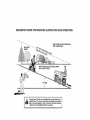
I!, SLOPE
and feet and
could result in
OPERATION
Slopes are a major factor related to lossof-control and tipover accidents, which
can result in severe injury or death° All
slopes require extra caution.
If you
cannot back up the slope or if you feel
uneasy on it, do not mow it.
DO:
• Mow up and down slopes, not across.
- Remove obstacles such as rocks, tree
limbs, etc.
• Watch for holes, ruts, or bumps.
Uneven terrain could overturn the
machine, Tall grass can hide obstacles,
. Use slow speed.
Choose a low gear
so that you will not have to stop or shift
while on the slope
. Follow the manufacturer's
recommendations for wheel weights or counterweights to improve stability
• Use extra care with grass catchers or
other attachments,,
These can change
the stability of the machine.
• Keep all movement on the slopes slow
and gradual
Do not make sudden
changes in speed or direction.
• Avoid starting or stopping on a slope. If
tires lose traction,
disengage the
blades and proceed slowly straight
down the slope.
DO NOT:
o Do not turn on slopes unless necessary, and then, turn slowly and gradually downhill, if possible
. Do not mow near drop-offs, ditches, or
embankments.
The mower could
suddenly turn over if a wheel is over
the edge of a cliff or ditch, or if an edge
caves in,
• Do not mow on wet grass. Reduced
traction could cause sliding,
• Do not try to stabilize the machine by
putting your foot on the ground,
• Do not use grass catcher on steep
slopes
III. CHILDREN
.
Tragic accidents can occur if the operator
is not alert to the presence of children.
Children are often attracted to the
•
machine and the mowing activity,. Never
assume that children will remain where
you last saw them
• Keep children out of the mowing area
and under the watchful care of another
responsible
adult.,
• Be alert and turn machine off if children
enter the area.
•
.
•
. Before and when backing, took behind
and down for small children°
° Never carry children° They may fall off
and be seriously injured or interfere
with safe machine operation,
• Never allow children to operate the
machine°
, Use extra care when approaching
blind
corners, shrubs, trees, or other objects
that may obscure vision,
,
,
IV. SERVICE
•
• Use extra care in handling gasoline
and other fuels. They are flammable
and vapors are explosive.
Use only an approved container.
-Never remove gas cap or add fuel
with the engine running. Allow
engine to cool before refueling,. Do
not smoke.
Never refuel the machine indoors°
- Never store the machine or fuel
container inside where there is an
open flame, such as a water heater..
.
• Be sure the area is clear of other
•
.
°
•
. Be alert and turn machine
enter the area°
people before mowing. Stop machine if
anyone enters the area.
Never carry passengers
or children
even with the blades off.
Do not mow in reverse unless absolutely necessary. Always look down
and behind before and while backing,
Never carry children They may fall off
and be seriously injured or interfere
with safe machine operation..
Keep children out of the mowing area
and under the watchful care of another
responsible
adult.
Never run a machine inside a closed
area.
Keep nuts and bolts, especially blade
attachment bolts, tight and keep
equipment
in good condition,
Never tamper with safety devices.
Check their proper operation regularly.
Keep machine free of grass, leaves, or
other debris build-up. Clean oi! or fuel
spillage.. Allow machine to cool before
storing..
Stop and inspect the equipment if you
strike an object. Repair, if necessary,
before restarting,.
Never make adjustments
or repairs
with the engine running.
Grass catcher components
are subject
to wear, damage, and deterioration,
which could expose moving parts or
allow objects to be thrown.
Frequently
check components
and replace with
manufacturer's
recommended
parts,
when necessary,
Mower blades are sharp and can cut..
Wrap the blade(s) or wear gloves, and
use extra caution when servicing them°
Check brake operation frequently.
Adjust and service as required,,
off if children
, Before and when backing, look behind
and down for small children,
.
Mow up and down slopes (15 ° Max),
not across.
• Remove obstacles such as rocks, tree
limbs, etc.
• Watch for holes, ruts, or bumps,
Uneven terrain could overturn the
machine.. Tal! grass can hide obstacles.
4
• Use slowspeed..Choosea low gearso
that you will not haveto stop or shift
while on the slope,
• Avoidstartingor stoppingon a slope_If
tires lose traction,disengagethe
blades and proceedslowly straight
down the slope.
° if machinestops while going uphill,
disengageblades,shift into reverse
and back down slowly.
• Do not turn on slopes unlessnecessary, andthen, turn slowly andgradually downhill, if possible.
,_
CAUTION:
Tow only the attachments
that are recommended
by and comply
with specifications
of the manufacturer
of
your tractor, Use common sense when
towing Operate only at the lowest
possible speed when on a slope° Too
heavy of a load, while on a slope, is
dangerous.
Tires can lose traction with
the ground and cause you to lose control
of your tractor,
_I_,WARNING:
Engine exhaust, some of
its constituents,
and certain vehicle
components
contain or emit chemicals
known to the State of California to cause
cancer and birth defects or other reproductive harm.
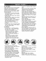
_,Look for this symbolto pointout
importantsafetyprecautions.It means
CAUTION!!! BECOMEALERT!!!YOUR
SAFETYtS INVOLVED
_WARNING:
Battery posts, terminals
and related accessories
contain lead and
lead compounds,
chemicals known to the
State of California to cause cancer and
birth defects or other reproductive
harm.
Wash hands after handling.
Z_
CAUTION:
In order to prevent
accidental starting when setting up,
transporting,
adjusting or making repairs,
always disconnect
spark plug wire and
place wire where it cannot contact spark
plug.
CAUTION:
Do not coast down a hill
in neutral, you may lose control of the
tractor,
5
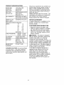
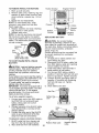
PRODUCT
SPECIFICATIONS
OIL CAPACITY:
WtFILTER: 3,5 PINTS
WlOFILTER: 3.0 PINTS
Should you experience
any problem you
cannot easily remedy, please contact a
Sears or other qualified service center,.
We have competent, well-trained
technicians and the proper tools to service or
repair this tractor.
Please read and retain this manual., The
instructions
wilt enable you to assemble
and maintain your tractor properly.
Always observe the "SAFETY RULES'L
SPARK
CHAMPION
REPAIR
GASOLINE
CAPACITY
AND TYPE:
1o25 GALLONS
UNLEADED
REGULAR
OlLT'YPE
SAE 30 (ABOVE
SAE 5W-30
API-SF-SJ):
(BELOW
PLUG:
32°F)
32°F)
RC12YC
'GAP: .030") , ,
GROUND SPEED FORWARD:
MPH):
TIRE PRESSURE:
I sT
2 ND
3 "D
4 TM
5 TM
6 TM
REVERSE:
FRONT:
REAR:
A Repair Agreement
is available on this
product.
Contact your nearest Sears
store for details.
I .2
1,5
2.4
3.5
4.8
5.3
1.5
CUSTOMER
3 AMPS BATTERY
5 AMPS HEADLIGHTS
BATTERY:
AMPtHR:
25
MIN. CCA:
t90
CASE SIZE: U 1R
BLADE BOLT
TORQUE:
27-35
RESPONSIBILITIES
• Read and observe the safety
• Follow a regular schedule in
ing, caring for and using your
. Follow the instructions
under
nance" and "Storage" sections
owner's manual.
14 PSI
10 PSI
CHARGING
SYSTEM:
AGREEMENT
rules,
maintaintractor,
"Mainteof this
,_WARNING:
This tractor is equipped
with an internal combustion
engine and
should not be used on or near any
unimproved
forest-covered,
brushcovered or grass-covered
land unless the
engine's exhaust system is equipped with
a spark arrester meeting applicable local
or state laws (if any)° If a spark arrester is
used, it should be maintained
in effective
working order by the operator,.
In the state of California the above is
FT. LBS
CONGRATULATIONS
on your purchase
of a new tractor. It has been designed,
engineered
and manufactured
to give
you the best possible dependability
and
performance.
required by law (Section 4442 of the
California
Public Resources
Code)..
Other states may have similar laws.
Federal laws apply on federal lands, A
spark arrester for the muffler is available
through your nearest Sears service
center (See REPAIR PARTS section of
this manual).
6
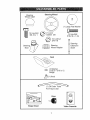
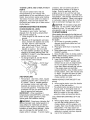
Steering
Steering
Wheel insert
Wheel
(1) Large Fiat Washer
(1) Hex Bolt
3/8-16 x 1
(1) Lock
washer 3/8
(1) Hex Bolt
5/16-18 x 1-1/4
(1) Locknut
5/16-18
Steering
Boot
Steering
Extension
Shaft
Steering
, Wheel Adapter
,
O
l) Washer
7/32 x 1-3/16 x 12
Gauge
_(1
) Knob
For Future Use
Keys
F-7
Slope
Sheet
Video Cassette
7
Your new tractor has been assembled at the factory with exception of those parts left
unassembled
for shipping purposes,, To ensure safe and proper operation of your
tractor all parts and hardware you assemble must be tightened securely,, Use the
correct tools as necessary to insure proper tightness,,
TOOLS
REQUIRED
FOR ASSEMBLY
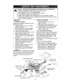
8,
Remove protective materials from
tractor hood and grill,
IMPORTANT:
Check for and remove any
staples in skid that may puncture tires
where tractor is to rol! off skid
A socket wrench set will make assembly
easier,. Standard wrench sizes you need
are listed below.
(I) 9/t6" wrench
(1) Pliers
(2) !/2"wrench
(I) Utility knife
(1) Tire pressure
gauge
When right or left hand is mentioned in
this manual, it means, from your point of
view, when you are in the operating
position (seated behind the steering
wheel).
TO REMOVETRACTOR
FROM
CARTON
UNPACK
G
Large Flat
Washer
CARTON
1. Remove all accessible
loose parts
and parts cartons from carton.
2 Cut, from top to bottom, along lines on
all four corners of carton, and lay
panels flat..
3. Check for any additional loose parts
or cartons and remove_
Shaft
5116 Locknut,
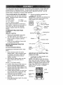
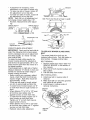
BEFORE REMOVING TRACTOR
FROM SKID
ATTACH STEERING WHEEL
ASSEMBLE
BOOT
EXTENSION
Lower
Steerlng/'_,.
SHAFT AND
HOWTO
CHECK
_'" ""
".'-
so
they are pointing straight forward.
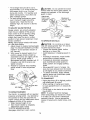
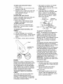
4o Remove steering wheel adapter from
steering wheel and slide adapter onto
steering shaft extension.
5, Position steering wheel so cross bars
are horizontal (left to right) and slide
inside boot and onto adapter,,
6 Assemble large flat washer, 318 lock
washer, 318 hex bolt and tighten
securely.
7, Snap steering wheel insert into center
of steering wheel,.
SET
_I
"_',
-,_,
'
t
Tab
Slots
", '/
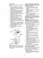
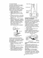
UPYOURTRACTOR
BATTERY
1, Lift seat pan to raised position and
open battery box dooL
NOTE: If this battery is put into service
after month and year indicated on label
(label located between terminals) charge
battery for minimum of one hour at 6-10
amps. (See "BATTER"(" in Maintenance
section of this manual for charging
instructions)_
Tighten securely.
2. Place tabs of steering boot over tab
slots in dash and push down to
secure.
INSTALL STEERING WHEEL
3. Position front wheels of the tractor
'
Shaft
1. Slide extension shaft onto lower
steering shafL Align mounting holes
in extension and lower shafts and
install 5116 hex bolt and locknut,
t16 Hex Bolt
Seat
Terminal
Battery
Door
8
INSTALL
SEAT
TO ROLLTRACTOR
Operation
section
Adjust seat before tightening
adjustment
knob,
1, Remove adjustment knob and flat
washer securing seat to cardboard
packing and set aside for assembly of
seat to tractor,.
2o Pivot seat upward and remove from
the cardboard packing, Remove the
cardboard packing and discard.
3,, Place seat on seat pan so head of
shoulder bolt is positioned over large
slotted hole in pan.
4 Push down on seat to engage
shoulder bolt in slot and pull seat
towards rear of tractor,
5, Pivot seat and pan forward and
assemble adjustment
knob and flat
washer Ioosely_ Do not tighten_
6. Lower seat into operating position and
sit in seat.,
7, Slide seat until a comfortable
position
is reached which allows you to press
clutch/brake
pedal all the way down,,
8, Get off seat without moving its
adjusted position,
9, Raise seat and tighten adjustment
knob securely,
function
OFF SKID
for location
(See
and
of controls)
1, Press lift lever plunger and raise
attachment lift lever to its highest
position,
2, Release parking brake by depressing
cbtch/brake
pedal,
3 Place gearshift lever in neutral (N)
position,,
4. Roll tractor forward off skid.
5, Remove banding holding discharge
guard up against tractor,,
TO DRIVE TRACTOR OFF SKID (See
Operation
section for location
and
function of controls)
_WARNING:
Before starting, read,
understand and follow all instructions
in
the Operation section of this manual, Be
sure tractor is in a well-ventilated
area,
Be sure the area in front of tractor is clear
of other people and objects°
1., Be sure all the above assembly steps
have been completed,
2. Check engine oil level and fitl fuel
tank with gasoline,,
3, Sit on seat in operating position,
depress clutch!brake
pedal and set
the parking brake,
4 Place gear shift lever in neutral (N)
position
5, Press lift lever plunger and raise
attachment lift lever to its highest
position.
6_ Start the engine. After engine has
started, move throttle control to idle
position,
7, Depress clutch/brake
pedal into full
"BRAKE" position and hold, Move
gearshift lever to 1st gear°
8. Slowly release clutch/brake
pedal and
slowly drive tractor off skid,
9 Apply brake to stop tractor, set parking
brake and place gearshift lever in
neutral position.
1O,Turn ignition key to "OFF" position.
Continue with the instructions
that follow,
Seat
Seat Pan-_
Bolt
Flat Washer
Adj
NOTE: You may now roll or drive your
tractor off the skid, Follow the appropriate
instruction below to remove the tractor
from the skid,
CHECKTIRE
PRESSURE
The tires on your tractor were overinflated
at the factory for shipping purposes,
Correct tire pressure is important for best
cutting performance.
• Reduce tire pressure to PSI shown in
"PRODUCT
SPECIFICATIONS"
section
of this manual.
9
CHECK
DECK LEVELNESS
",/CHECKLIST
Before you operate and enjoy your new
tractor, we wish to assure that you receive
the best performance
and satisfaction
from this Quality Product.
Please review the following checklist:
./'All assembly instructions
have been
completed°
./No remaining loose parts in carton.
./Battery
is properly prepared and
charged.
(Minimum
1 hour at 6 amps).
,/Seat
is adjusted comfortably
and
tightened
securely_
./All tires are properly inflated,
(For
shipping purposes, the tires were
overinfiated
at the factory).
./Be sure mower deck is properly leveled
side-to-side/front-to-rear
for best cutting
results,, (Tires must be properly inflated
for leveling)_
./Check
mower and drive belt&, Be sure
they are routed properly around pulleys
and inside all belt keepers
./Check
wiring,
See that all connections
are still secure and wires are properly
clamped.
While learning how to use your tractor,
pay extra attention to the following
important
items:
,/Engine
oil is at proper level,,
./Fuel tank is filled with fresh, clean,
regular unleaded
gasoline,,
,/Become
familiar with all controls - their
location and flJnction
Operate them
before you start the engine,
./Be sure brake system is in safe
operating
condition_
For best cutting results, mower housing
should be properly leveled.
See "TO
LEVEL MOWER HOUSING" in the
Service and Adjustments
manual,,
section
CHECK
POSITION
ALL
FOR
PROPER
of this
OF
BELTS
See the figures that are shown for
replacing motion and mower blade drive
belts in the Service and Adjustments
section of this manual,, Verify that the
belts are routed correctly.
CHECK
BRAKE
SYSTEM
After you learn how to operate your
tractor, check to see that the brake is
properly adjusted., See "TO ADJUST
BRAKE" in the Service and Adjustments
section of this manual
INSTALL
MULCHER
PLATE
(If previously
removed)
1o Raise and hold deflector shield in
upright position.
2. Place front of mulcher plate over front
of mower deck opening and slide into
place, as shown.
3. Hook front latch into hole on front of
mower deck,,
4o Hook rear latch into hole on back of
mower deck,
,,_kCAUTION:
Do not remove deflector
shield from mower. Raise and hold shield
when attaching mulcher plate and allow it
to rest on plate while in operation.
Mulcher
Plate
De1
Shield
Latch
Hooks
TO CONVERTTO
DISCHARGING
BAGGING
OR
Simply remove mulcher plate and store in
a safe place° Your mower is now ready for
discharging
or installation of optional
grass catcher accessory,,
NOTE: It is not necessary to change
blades, The mulcher blades are designed for discharging
and bagging also,
10
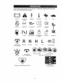
These symbols may appear on your tractor
Learn and understand
their meaning,
or in literature
supplied
with the product.
,e
BATTERY
CAUTION OR
WARNING
REVERSE
FORWARD
FAST
SLOW
(I-- og
ENGINE ON
ENGINE OFF
OIL PRESSURE
LIGHTS ON
OVER TEMP
LIGHT
MOWER HEIGHT
PARKING BRAKE
LOCKED
IXl
FUEL
A'FTACHMENT
CLUTCH ENGAGED
IGNITION
CHOKE
REVERSE
NEUTRAL
ATTACHMENT
CLUTCH DISENGAGED
HIGH
LOW
KEEP AREA CLEAR
UNLOCKED
PARKING
MOWER LIFT
BRAKE
SLOPE HAZARDS
(SEE SAFETY RULES SECTION)
FREE WHEEL
DANGER, KEEP HANDS AND FEET AWAY
(Aulomatic Models only)
!1
KNOWYOURTRACTOR
READ THIS OWNER'S
YOUR TRACTOR
MANUAL
AND SAFETY
RULES
BEFORE
OPERATING
Compare the illustrations
with your tractor to familiarize yourself with the locations
various controls and adjustments
Save this manual for future reference,,
of
Light Switch
Ignition Switch
Attachment
Clutch
Lever \.
Lift
Ammeter
ThrottletChoke
Control
ClutchtBrake
Pedal
_
Lever
Plunger
Attachment
Lift Lever
©
Height
Adjustment
Indicator
""-'"-VC"_
"::-"
Parking Brake Lever
Gearshift Lever
Our tractors
conform to the safety standards
National Standards Institute.
of the American
IGNITION SWITCH - Used for starting
and stopping the engine.
LIFT LEVER PLUNGER - Used to
release attachment
lift lever when
changing its position_
LIGHT SWITCH - Turns the headlights on
and off.
PARKING BRAKE LEVER - Locks
clutch/brake
pedal into the brake
position.
THROTTLE/CHOKE
CONTROL _ Used
for starting and controlling engine speed,
AMMETER
- Indicates charging (+) or
discharging
(-) of battery.
ATTACHMENT
CLUTCH LEVER - Used
to engage the mower blades, or other
attachments
mounted to your tractor°
ATTACHMENT
LIFT LEVER - Used to
raise, lower, and adjust the mower deck
or other attachments
mounted to your
tractor.
CLUTCH/BRAKE
PEDAL - Used for
declutching
and braking the tractor and
starting the engine,
GEARSHIFT
LEVER - Selects the speed
and direction of tractor.
12
The operation of any tractor can result in foreign objects thrown into
the eyes, which can result in severe eye damage
Always wear safety
glasses or eye shields while operating your tractor or performing any
adjustments or repairs. We recommend
a wide vision safety mask over
spectacles or standard safety glasses.
HOWTO
USEYOURTRACTOR
TO SET PARKING
IMPORTANT:
Leaving the ignition switch
in any position other than "OFF" will
cause the battery to be discharged,
(dead).
NOTE: Under certain conditions when
tractor is standing idle with the engine
running, hot engine exhaust gases may
cause "browning" of grass. To eliminate
this possibility, always stop engine when
stopping tractor on grass areas,
BRAKE
'four tractor is equipped with an operator
presence sensing
switch_ When engine
is running, any attempt by the operator to
leave the seat without first setting the
parking brake will shut off the engine.
1. Depress clutch/brake
pedal into full
"BRAKE" position and hold.
2, Place parking brake lever in "ENGAGED" position and release
pressure from clutch/brake
pedal°
Pedal should remain in "BRAKE"
position,
Make sure parking brake will
hold tractor secure,
Attachment Clutch Lever
"Engaged"
Position
(_,CAUTION:
Always stop tractor
completely, as described
above, before
leaving the operator's position; to empty
grass catcher, etc.
TO USETHROTTLE
CONTROL
Always operate engine at full throttle,
, Operating engine at less than full
throttle reduces the battery charging
rate°
• Full throttle offers the best bagging
and mower performance,.
Ignition Key
"Disengaged"
Position
Parking Brake
ed"
Position
TO MOVE FORVVARD AND
BACKWARD
Brake Pedat_
The direction and speed of movement
is
controlled by the gearshift
lever.
1. Start tractor with clutchfbrake
pedal
depressed
and gearshift lever in
neutral (N) position,
2. Move gearshift lever to desired
position.
3 Slowly release clutchlbrake
pedal to
start movement,.
IMPORTANT:
Bring tractor to a complete
stop before shifting or changing gears.
Failure to do so will shorten the useful life
of your transaxle_
rshift
Lever
"Disengaged"
Position
Position
STOPPING
MOWER
BLADES
-
' To stop mower blades,move
attachment clutch lever to "DISENGAGED"
position°
GROUND
DRIVE-
TO ADJUST
, To stop ground drive, depress clutch/
brake pedal into full "BRAKE" position.,
• Move gearshift
lever to neutral (N)
position,,
ENGINE. Move throttle control to slow position,
NOTE: Failure to move throttle control to
slow position and allowing engine to idle
before stopping may cause engine to
"backfire"°
, Turn ignition key to "OFF" position and
remove key. Always remove key when
leaving tractor to prevent unauthorized
use.
. Never use choke to stop engine,
MOWER
CUTTING
HEIGHT
The position of the attachment
lift lever
determines the cutting height°
. Grasp lift lever.
. Press plunger with thumb and move
lever to desired position°
The cutting height range is approximately 1-112 to 4",, The heights are
measured from the ground to the blade
tip with the engine not running, These
heights are approximate
and may vary
depending
upon soil conditions,
height of
grass and types of grass being mowed.,
t3
. The average lawn should be cut to
approximately
2-I/2 inches during the
cool season and to over 3 inches
during hot months,
For healthier and
better looking lawns, mow often and
after moderate growth,
• For best cutting performance,
grass
over 6 inches in height should be
mowed twice° Make the first cut
relatively high; the second to desired
height,,
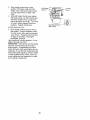
TO ADJUST
GAUGE
_,CAUTION:
Do not operate the mower
without either the entire grass catcher, on
mowers so equipped, or the discharge
guard in place.
Attachment
Clutch Lever
"En
Position
Attachemnt
Lever High
:. Position
!
Low
Position
WHEELS
Gauge wheels
are properly adjusted
when they are slightly off the ground
when mower is at the desired cutting
height in operating position, Gauge
wheels then keep the deck in proper
position to help prevent scalping in most
terrain conditions.
NOTE: Adjust gauge wheels with tractor
on a flat level surface_
Deflector
Shield
TO OPERATE
_CAUTION:
Do not drive up or down
hills with slopes greater than 15 ° and do
not drive across any slope.
• Choose the slowest speed before
starting up or down hills.
o Avoid stopping or changing speed on
hills.
• if slowing is necessary, move throttle
control lever to s!ower position.
• If stopping is absolutely necessary,
push clutch/brake
pedal quickly to
brake position and engage parking
brake,
1. Adjust mower to desired cutting height
(See "TO ADJUST MOWER CUTTING
HEIGHT" in the Operation section of
this manual).
2 With mower in desired height of cut
position, gauge wheels should be
assembled so they are slightly off the
groun&
install gauge wheel in
appropriate
hole with shoulder bolt, 3/
8 washer, and 3/8-16 Iocknut and
tighten securely,
3 Repeat for opposite side installing
gauge wheel in same adjustment
hole.
Gauge
Wheel
Mountin
Bracket
ON HILLS
.
Move gearshift lever to 1st gear
Be
sure you have allowed room for tractor
to roll slightly as you restart movement,
. To restart movement, slowly release
parking brake and clutch/brake
pedal.
o Make all turns slowly.
TO TRANSPORT
3/8-16
Locknut
Shoulder Bolt
3/8
Gauge Wheel
TO OPERATE
MOWER
Your tractor is equipped with an operator
presence sensing switch, Any attempt by
the operator to leave the seat with the
engine running and the attachment clutch
engaged will shut off the engine,
1, Select desired height of cut,
2. Start mower blades by engaging
attachment clutch control.
TO STOP MOWER BLADESdisengage attachment
clutch control..
• Raise attachment lift to highest position
with attachment lift control.
• When pushing or towing your tractor,
be sure gearshift lever is in neutral (N)
position.
• Do not push or tow tractor at more than
five (5) MPH
NOTE: To protect hood from damage
when transporting your tractor on a truck
or a trailer, be sure hood is closed and
secured to tractor° Use an appropriate
means of tying hood to tractor (rope, cord,
etco).
14
TOWING
MENTS
CARTS
AND OTHER
ATTACH-
problems, the fuel system should be
emptied before storage of 30 days or
longer° Drain the gas tank, start the
engine and let it run until the fuel lines
and carburetor are empty. Use fresh fuel
next season. See Storage Instructions for
additional information.
Never use engine
or carburetor
cleaner products in the flJel
tank or permanent damage may occur.
Tow only the attachments
that are
recommended
by and comply with
specifications
of the manufacturer
of your
tractor. Use common sense when towing
Too heavy of a load, while on a slope, is
dangerous, Tires can lose traction with
the ground and cause you to lose control
of your tractor.
BEFORE
CHECK
_I_CAUTION:
Fill to bottom of gas tank
filler neck. Do not overfill. Wipe off any
spilled oil or fuel. Do not store, spill or
use gasoline near an open flame.
TO START ENGINE
STARTING THE ENGINE
ENGINE
OIL LEVEL
The engine in your tractor has been
shipped, from the factory, already filled
with summer weight oil.
I. Check engine oil with tractor on level
ground.
2. Remove oil fill cap/dipstick
and wipe
clean, reinsert the dipstick and screw
cap tight, wait for a few seconds,
remove and read oil tevel_ If necessary, add oil until "FULL" mark on
dipstick is reached.
Do not overfill.
, For cold weather operation you should
change oil for easier starting (See "OIL
VISCOSITY CHART" in the Maintenance
When starting the engine for the first time or if
the engine has run out of fuel, it will take extra
cranking time to move fuel from the tank to
the engine..
1o Sit on seat in operating position,
depress clutchlbrake
pedal and set
parking brake°
2. Place gear shift lever in neutral (N)
position
3. Move attachment clutch to "DISENGAGED" position.
4. Move throttle control to choke position..
NOTE: Before starting, read the warm and
cold starting procedures below,
5. Insert key into ignition and turn key
clockwise to "START" position and
release key as soon as engine starts.
Do not run starter continuously
for
more than fifteen seconds per minute.
If the engine does not start after
several attempts, move throttle control
to fast position, wait a few minutes and
try again.. If engine still does not start,
move the throttle control back to the
choke position and retry°
section of this manual).
. To change engine oil, see the Maintenance section in this manual.
Oil Fili Cap/
Dipstick
ADD
GASOLINE
• Fill fuel tank.. Use fresh, clean, regular
unleaded gasoline with a minimum of
87 octane.
(Use of leaded gasoline
will increase carbon and lead oxide
WARM WEATHER
above)
6. When engine starts, move the throttle
control to the fast position_
• The attachments
and ground drive can
now be used. If the engine does not
accept the load, restart the engine and
allow it to warm up for one minute
using the choke as described above_
deposits and reduce valve life). Do not
mix oil with gasoline_ Purchase fuel in
quantities that can be used within 30
days to assure fuel freshness..
IMPORTANT:
When operating in
temperatures
below32°F(0°C),
use fresh,
clean winter grade gasoline to help
insure good cold weather starting,
_,WARNING:
Experience
indicates that
alcohol blended fuels (called gasohol or
using ethanol or methanol) can attract
moisture which leads to separation
and
formation of acids during storage.
Acidic
gas can damage the fuel system of an
engine while in storage.
To avoid engine
STARTING (50 ° F and
COLD WEATHER
below)
6
15
STARTING ( 50 ° F and
When engine starts, allow engine
run with the throttle control in the
to
choke position until the engine runs
roughly, then move throttle control to
fast position, This may require an
engine warm-up period from several
seconds to several minutes, depending on the temperature.
• The attachmentscan also be used
during the enginewarm-up period..
NOTE: Ifata highaltitude(above3000feet)
or in coldtemperatures
(below32 F)the
carburetorfuelmixturemayneedto be
adjustedfor bestengineperformanceSee
"TOADJUSTCARBURETOR"
intheService
andAdjustments
sectionof thismanual..
MOWINGTIPS
• Tire chainscannot be usedwhen the
mowerhousingis attachedto tractor.
• Mowershould be properlyleveledfor
bestmowingperformance. See "TO
LEVELMOWERHOUSING"in the
Serviceand Adjustmentssectionof this
manual.
, The left hand side of mowershouldbe
usedfor trimming.
. Driveso that clippingsare discharged
ontothe area that has been cut. Have
the cut areato the right of the tractor'.
This will result in a more even distribution of clippings and more uniform
cutting,.
• When mowinglarge areas, start by
turningto the right so that clippingswill
dischargeaway from shrubs,fences,
driveways,etc, After one or two
rounds,mow in the oppositedirection
makingleft hand turns untilfinished
• if grass is extremelytall, it shouldbe
mowedtwice to reduceload and
possiblefire hazard from dried clippings, Makefirst cut relativelyhigh;the
second to the desired height.
° Do not mow grasswhen it is wet,. Wet
grass will plug mowerand leave
undesirableclumps. Allow grassto dry
before mowing.
• Always operate engine at full throttle
when mowing to assure better mowing
performance
and proper discharge of
material.
Regulate ground speed by
selecting a low enough gear to give the
mower cutting performance
as well as
the quality of cut desired.
• When operating attachments,
select a
ground speed that will suit the terrain
and give best performance
of the
attachment
being used.
,
C----__J
16
MULCHING
MOWINGTIPS
IMPORTANT:
For best performance,
keep mower housing free of built-up
grass and trash_ Clean after each use°
o The special mulching blade will recut
the grass clippings many times and
reduce them in size so that as they fall
onto the lawn they will disperse into the
grass and not be noticed, Also, the
mulched grass will biodegrade
quickly
to provide nutrients for the lawn
Always mulch with your highest engine
(blade) speed as this will provide the
best recutting action of the blades_
° Avoid cutting your lawn when it is weL
Wet grass tends to form clumps and
interferes with the mulching action.
The best time to mow your fawn is the
early afternoon,
At this time the grass
has dried and the newly cut area will
not be exposed to the direct sun..
- For best results, adjust the mower
cutting height so that the mower cuts off
only the top one-third of the grass
blades. For extremely heavy mulching,
reduce your width of cut on each pass
and mow slowly°
. Certain types of grass and grass
conditions may require that an area be
mulched a second time to completely
hide the clippings..
When doing a
second cut, mow across or perpendicular to the first cut path.
, Change your cutting pattern from week
to week. Mow north to south one week
then change to east to west the next
week. This will help prevent matting
and graining of the lawn.
Max t13"
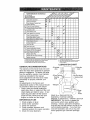
MAINTENANCE SCHEDULE
./'_+__./_o_o_._
FiLL 1N DATES
/__'_,
s ooco
REGULAR
ii
Check Brake Operaiion
Check Tire Pressure
T
Check Operator Presence
lntedock Systems
R
Check forLoose
A
Sharpen/Replace
T
L_ii_"iiOn
chert
0
Check Battery Level
R
_!
SERVICE
tM#
_
6#_
_€
V _
1_7
Mower Blades
_4
......................
_ .............
Terminals
!MI
_#',
Adjusl Melion Drive Belt(s) Tension
V_s
Check Engine Oil Level
_/'
Change Engine Oil
V'
..............................................
_t2,_
E
N
=cle,nA![Filter
...........
G
"'i'n'spect Muffledspark
....................
I/z
Arreeler
....................
_
'
:Oil Fiiier {if equipped)
_
Replace Spark Plug
Replace
Air Fitter
Paper
Replace
Fuei Fitter
'
V_,= .......
F_ns
E,g_ne
co0,ng
NE
!/
......
V'=
Clean Alr Screen
....
Re';iac;
_
V t
Coating
Adius[ BladeBell(s)
Tension
/
_
Cadridg,e
.................
V _'
_/'_
! V °
., Change more ogen when opemling ueder a heavy load at in high amblenl tempr_reture_
2 - Service more often when operating in dgly or du.,..lyr:ondiliens
3 - If equipped wilh ofl II_er, change off every 50 hmlrs
4 _ Replace biedos more enen when mowing In_andy soil
I
5 - it equipped wilh ad}ustable sys]em
6 - Not req_imd it equipped with me_rflenencmfree betlory
7 • Tighten
#Phi
axle pivot
RECOMMENDATIONS
The warranty on this tractor does not cover
items that have been subjected to operator
abuse or negligence°
To receive full value
from the warranty', operator must maintain
tractor as instructed in this manual_
Some adjustments will need to be made
periodically to properly maintain your
tractor.
All adjustments in the Service and
Adjustments section of this manual should
be checked at least once each season
, Once a year you should replace the
spark plug, clean or replace air filter, and
check blades and belts for wear. A new
spark plug and clean air filter assure
proper air-fuel mixture and help your
engine run better and last longer.
BEFORE
I,
2_
3.
4.
5
EACH USE
Check engine oil level.
Check brake operation.
Check tire pressure_
Check operator presence and
interlock systems for proper operation.
Check for loose fasteners_
bolt to 35 I|-IbS
maxtmL_m
Do hal overtighton
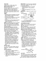
LUBRICATION
GENERAL
,/ ,
and
Fasieners
Ctean Batteryand
Check Transaxle
if
S
Zerk
CHART
)indle
Zerk
r;
_)Front Wheel
Bearing
Zerk
Wheel
Bearing Zerk
@Engine /
l
l
i
|
f
l
_Gear-r ' _ shift
t
_
_' Pivots
(DSAE 30 or 10w30 MOTOR OIL
@GENERAL PURPOSE GREASE
@REFER TO Maintenance "ENGINE" SECTION
IMPORTANT:
Do not oil or grease the
pivot points which have special nylon
bearings,
Viscous lubricants will attract
dust and dirt that will shorten the life of the
self-lubricating
bearings.
If you feel they
must be lubricated, use only a dry, powdered graphite type lubricant sparingly
17
_
--!
|
t
TRACTOR
Always observe safety rules when
performing
any maintenance..
BRAKE OPERATION
If tractor requires more than six (6) feet
stopping distance at high speed in
highest gear, then brake must be adjustedo (See "TO ADJUST BRAKE" in the
Service and Adjustments
section of this
manual)..
• Maintain proper air pressure in all tires
(See "PRODUCT SPECIFICATIONS"
section of this manual),
• Keep tires free of gasoline, oil, or insect
control chemicals which can harm
rubber°
• Avoid stumps, stones, deep ruts, sharp
objects and other hazards that may
cause tire damager
NOTE: To seal tire punctures and prevent
flat tires due to slow leaks, tire sealant
may be purchased from your local parts
dealer. Tire sealant also prevents tire dry
rot and corrosion.
OPERATOR
PRESENCE
SYSTEM
Be sure operator presence and interlock
systems are working properly.
If your
tractor does not function as described,
repair the problem immediatelyr
• The engine should not start unless the
clutch/brake
pedal is fully depressed
and attachment clutch control is in the
disengaged
position..
. When the engine is running, any
attempt by the operator to leave the
seat without first setting the parking
brake should shut off the engine.
. When the engine is running and the
attachment
clutch is engaged, any
attempt by the operator to leave the
seat should shut off the engine.
, The attachment clutch should never
operate unless the operator is in the
seal
BLADE CARE
For best results mower blades must be
kept sharp. Replace bent or damaged
blades°
BLADE
REMOVAL
1.. Raise mower to highest position to
allow access to blades.
2, Remove hex bolt, lock washer and flat
washer securing blade.
3,. Install new or resharpened
blade with
trailing edge up towards deck as
shown.
IMPORTANT:
To ensure proper assembly,
center hole in blade must atign with star
on mandrel assembly_
4. Reassemble
hex bolt, lock washer
and flat washer in exact order as
shown,
5. Tighten bolt securely (27-35 Ft, Lbs.
torque)_
IMPORTANT:
Blade bolt is grade 8 heat
treated
Mandrel Assembly
Trailing Edge Up
Blade Center
Hole
Flat
Lock Washer
k_Hex
Bolt (Grade)
*A Grade 8 heat treated bolt can be identified
by six lines on the bolt head,
TO SHARPEN
BLADE
NOTE: We do not recommend sharpening blade - but if you do, be sure the
blade is balancedo
Care should be taken to keep the blade
balanced°
An unbalanced
blade will
cause excessive vibration and eventual
damage to mower and engine.
• The blade can be sharpened with a file
or on a grinding wheel.
Do not attempt
to sharpen while on the mower.
• To check blade balance, you will need
a 5/8" diameter steel bolt, pin, or a cone
balancero (When using a cone balancer, follow the instructions
supplied
with balancer.)
NOTE:
Do not use a nail for balancing
blade. The lobes of the center hole may
appear to be centered, but are not.
o Slide blade on to an unthreaded
portion of the steet bolt or pin and hold
the bolt or pin parallel with the ground.
If blade is balanced, it should remain in
a horizontal position,. If either end of
the blade moves downward,
sharpen
the heavy end until the blade is
balancedp_n'__
5/8" Bolt or
//
Center Hole
w._
BATTERY
Your tractor has a battery charging system
which is sufficient for normal use. However, periodic
charging
18 an automotive
charger
of the battery
wilt extend
with
its life.
. Keepbatteryand terminalsclean,
• Keepbatterybolts tight,
. Keepsmallvent holes open,
. Rechargeat 6-10 amperesfor I hour.
NOTE:The original equipmentbatteryon
your tractoris maintenancefree_Do not
attemptto open or removecapsor covers,,
Addingor checkinglevel of electrolyteis
not necessary,
TO CLEANBATTERYANDTERMINALS
Corrosionand dirt on the battery and
terminalscan causethe batteryto "leak"
power,,
1, Openbatterybox door,.
2, DisconnectBLACKbatter,/cablefirst
then RED batterycable and remove
batteryfromtractor.
3., Rinsethe batterywith plain water and
dry°
4. Cleanterminalsand battery cable
endswith wire brushuntil bright.
5. Coatterminalswith grease or petroleumjelly,
6, Reinstallbattery (See "CONNECT
BATTERY"in the Assemblysectionof
this manual).
V-BELTS
Check V-belts for deterioration
and wear
after 100 hours of operation and replace if
necessary° The belts are not adjustable.,
Replace belts if they begin to slip from
wear.
TRANSAXLE
COOLING
Keep transaxle free from build-up of dirt
and chaff which can restrict cooling.
ENGINE
LUBRICATION
Only use high quality detergent oil rated
with API service classification SF-SJo
Select the oil's SAE viscosity grade
according to your expected operating
temperature,
SAE VISCOSITY
Check
the crankcase
oii level before
starting the engine and after each eight (8)
hours of operation, Tighten oil fill cap/
dipstick securely each time you check the
oil level,
TO CHANGE
ENGINE
OIL
Determine temperature
range expected
before oil change.
All oil must meet API
service classification
SF-SJ.
• Be sure tractor is on level surface.
, Oil will drain more freely when warm,
• Catch oil in a suitable container.
1_ Remove oil fill captdipstick.
Be careful
not to allow dirt to enter the engine
when changing oil.,
2, Remove cap from end of drain valve
and install the drain tube onto the
fitting,
3. Unlock drain valve by pushing inward
slightly and turning counterclockwise.
4, To open, pull out on the drain valve_
5 After oil has drained completely,
close
and lock the drain valve by pushing
inward and turning clockwise until the
pin is in the locked position as shown,
6. Remove the drain tube and replace
the cap onto to the end of the drain
valve°
7, Refill engine with oil through oil fill
dipstick tube, Pour slowly° Do not
overfill, For approximate
capacity see
"PRODUCT SPECIFICATIONS"
section of this manual
8,
Use gauge on oil fill capldipstick
for
checking level_ Be sure dipstick cap is
tightened securely for accurate
reading,
Keep oil at "FULL" line on
dipstick.
Oil Drain Valve
Closed
and
Locked
Position
_ain
GRADES
Tube
!
Cap
;'F ............ ._9 _
°c .3'o"
O"
.='0"
"fEMF_ERATURE
3(}'
,1;_"
RANGE
32"
_'
ANTICIPATED
40"
50"
6"
BEFORE
80"
20"
NEXT
OtL
}g0'
_o"
,_o'i
CHANGE
NOTE: Although multi-viscosity
oils
(5W30, !0W30 etc,) improve starting in
cold weather, these multi-viscosity
oils will
result in increased oil consumption
when
used above 32°E Check your engine oil
level more frequently to avoid possible
engine damage from running low on oil
Change the oil after every 25 hours of
operation or at least once a year if the
tractor is not used for 25 hours in one year, 19
CLEAN
AIR SCREEN
Air screen must be kept free of dirt and
chaff to prevent engine damage from
overheating,
Clean with a wire brush or
compressed
air to remove dirt and
stubborn dried gum fibers,,
ENGINE
COOLING
FINS
Remove any dust, dirt or oil from engine
cooling fins to prevent engine damage
from overheating,
I. Removescrews from blowerhousing
and lift housingand dipsticktube
assemblyoff engine
2, Coveroil fill openingto prevententry
of dirL
3o Usecompressedair or stiff bristle
brush to thoroughlyclean engine
cooling fins.,
4r To reassemble,reverseabove
procedure.,
Screws
Blower Housing
IMPORTANT: Petroleum solvents, such as
kerosene, are not to be used to clean the
cartridge, They may cause deterioration of the
cartridge. Do not oil cartridge° Do not use
pressurized air to clean or dry cartridge.
C over _I--_P
Knob
_
...-J4"_
Cover /
Cartridge
..--.f__._ Nut
Screws
\ Paper
Foam Pre-Clea_er,,
_
"Cartridge
Base--_,._
MUFFLER
Dipstick Tube
Assembly
_Spark
__/Plug
Engine
Ig Fins
AIR FILTER
"four engine will not run properly using a
dirty air filter_ Clean the foam pre-cleaner
after every 25 hours of operation or every
season. Service paper cartridge every
100 hours of operation or every season,
whichever occurs first.
Sewice air cleaner more often under
dusty conditions°
1. Remove knob(s) and cover..
TO SERVICE
PRE-CLEANER
2,
3
4o
5,.
Slide foam pre-cleaner
off cartridge.
Wash it in liquid detergent and water.
Squeeze it dry in a clean cloth.
Saturate it in engine oil. Wrap it in
clean, absorbent cloth and squeeze to
remove excess oil.
NOTE: If very dirty or damaged, replace
pre-cteaner,,
6. Reinstall pre-cleaner
over cartridge.,
7, Reinstall cover and secure with
knob(s),
TO SERVICE
CARTRIDGE
1. Remove cartridge nut.
2. Carefully remove cartridge to prevent
debris from entering carburetor_
Clean base carefully to prevent debris
from entering carburetor.
3. Clean cartridge by tapping gently on
flat surface,
NOTE: If very dirty or damaged, replace
cartridge.
4. Reinstall cartridge, nut, precleaner,
cover and secure with knob(s),.
Inspect and replace corroded muffler and
spark arrester (if equipped) as it could
create a fire hazard andlor damage,
SPARK PLUGS
Replace spark plugs at the beginning of
each mowing season or after every 100
hours of operation, whichever occurs first,.
Spark plug type and gap setting are
shown in "PRODUCT
SPECIFICATIONS"
section of this manual..
IN-LINE
FUEL FILTER
The fuel filter should be replaced once
each season,
if fuel filter becomes
clogged, obstructing
fuel flow to carburetor, replacement
is required.
1_, With engine cool, remove filter and
plug fuel line sections.
2. Place new fuel filter in position in fuel
line with arrow pointing towards
carburetor.
3_, Be sure there are no fuel line leaks
and clamps are properly positioned.
4o immediately
wipe up any spilled
gasoline.
Clamp
F,,o,
CLEANING
• Clean engine, battery, seat, finish, etc.
of all foreign matter.
• Keep finished surfaces and wheels free
of all gasoline, oil, etc.
. Protect painted surfaces with automotive type wax,
We do not recommend
using a garden
hose to clean your tractor unless the
electrical system, muffler, air filter and
carburetor are covered to keep water out,.
Water in engine can result in a shortened
20engine
life.,
CAUTION: BEFORE
1.
2,
3o
4,
5.
6,
PERFORMING
ANY SERVICE OR ADJUSTMENTS:
Depress clutch/brake
pedal fully and set parking brake,
Place gearshift lever in neutral (N) position.
Place attachment clutch in "DISENGAGED"
position.,
Turn ignition key "OFF" and remove key
Make sure the blades and all moving parts have completely stopped,
Disconnect spark plug wire from spark plug and place wire where it cannot
come in contact with plug,
TO INSTALL MOWER
1, Raise attachment lift lever to its
TRACTOR
TO REMOVE MOWER
Mower will be easier to remove from the
highest position_
2. Slide mower under tractor with
discharge guard to right side of tractor,,
3. Lower lift lever to its lowest position.
4_ Install mower in reverse order of
removal instructions.
right side of tractor.
1. Place attachment clutch in "DISENGAGED" position.
2, Move attachment lift lever forward to
lower mower to its lowest position,
Roll belt off engine pulley.
Remove small retainer spring, and lift
clutch spring off pulley bolt.
5. Remove large retainer spring, slide
collar off and push housing guide out
of bracket.
6, Disconnect
antFswaybar from chassis
bracket by removing retainer spring°
7. Disconnect suspension
arms from
rear deck brackets by removing
retainer springs.
8, Disconnect front links from deck by
removing retainer springs_
9. Raise lift lever to raise suspension
arms, Slide mower out from under
tractor_
IMPORTANT:
if an attachment other than
the mower deck is to be mounted on the
tractor, remove the front links and hook
the clutch spring Into square hole in
frame.
TO LEVEL MOWER
3
4,
HOUSING
Adjust the mower while tractor is parked
on level ground or driveway,
Make sure
tires are properly inflated (See "PRODUCT SPECIFICATIONS"
section of this
manual)
If tires are over or
underinflated,
you will not properly adjust
your mower,
SIDE-TO-SIDE
ADJUSTMENT
• Raise mower to its highest position°
. At the midpoint of both sides of mower,
measure height from bottom edge of
mower to ground.,
Distance "A" on
both sides of mower should be the
same or within 1f4" of each other,,
Small Retainer Spring
Clutch Spring_
Link
Retainer Spring
Anti-Sway
Retainer Springs
(Both Sides)
Collar\
Housing Guide
Large
B ra,
Spring
21
• If adjustment
is necessary, make
adjustment
on one side of mower onlyo
, To raise one side of mower, tighten lift
link adjustment
nut on that side.
• To lower one side of mower, loosen lift
link adjustment
nut on that side.
NOTE:
Each full turn of adjustment
nut
wilt change mower height about 118'L
• Recheck measurements
after adjusting,
Bottom edge of
Bottom edge of
mower to
mower to
ground
"\,,,,__¢
f
_
Mandrel
Both Front Links Should be Equal in Length
ground
Nut
ension Arm
ItEII
Trur
Lift Link
_
Adjustment
FRONT-TO-BACK
ADJUSTMENT
Front Links
IMPORTANT:
Deck must be level side-toside.If the following front-to-back
adjustment is necessary, be sure to adjust both
front links equally so mower wilt stay
level side-to-side.
To obtain the best cutting results, the
mower housing should be adjusted so
that the front is approximately
1/8" to 1/2"
lower than the rear when the mower is in
its highest position_
Check adjustment
on right side of tractor.
Measure distance "D" directly in front and
behind the mandrel at bottom edge of
mower housing as shown.
• Before making any necessary adjustments, check that both front links are
equal in length.
Both links should be
approximately
10-3/8".
, If links are not equal in length, adjust
one link to same length as other link.
, To lower front of mower loosen nut "E"
on both front links an equal number of
turns.
• When distance "D" is 1/8" to t12" lower
TO REPLACE
BELT
MOWER
BLADE
DRIVE
The mower blade drive belt may be
replaced without tools. Park the tractor
level surface°
Engage parking brake.
BELT REMOVAL
on
-
1.. Remove mower from tractor (See "TO
REMOVE MOWER" in this section of
this manual).
2, Work belt off both mandrel pulleys and
idler pulleys..
3, Pull belt away from mower.
BELT INSTALLATION
-
4o Install new belt in reverse order of
removal,
5. Make sure belt is in all pulley grooves
and inside all belt guides..
6. Install mower in reverse order of
removal instructions,
Mandrel
Pulle
at front than rear, tighten nuts "F"
against trunnion on both front links.
• To raise front of mower, loosen nut "F"
from trunnion on both front links.
Tighten nut "E" on both front links an
equal number of turns°
• When distance "D" is 118" to 1/2" lower
at front than rear, tighten nut "F" against
trunnion on both front links..
• Recheck side-to-side
adjustment.
Mandrel
Pulley
22
Idler
TO ADJUST
BRAKE
Engine Pulley_
"(our tractor is equipped with an adjustable brake system which is mounted on
the right side of the transaxle.
If tractor requires more than six (6) feet
stopping distance at high speed in highest
gear on a Revel dry concrete or paved
surface, then brake must be adjusted,
I. Depress clutch/brake
pedal and
engage parking brake°
2.. Measure distance between brake
operating arm and nut "A" on brake
rod.
3, If distance is other than 1-1/2", loosen
jam nut and turn nut "A" until distance
becomes 1-t/2"o Retighten jam nut
against nut "A"..
4. Road test tractor for proper stopping
distance as stated above_ Readjust if
necessary_
If stopping distance is still
greater than six (6) feet in highest
gear, further maintenance
is necessary. Contact a Sears or other
qualified sen,ice center_,
WITH PARKING
Clutching Idler -"/
Stationary
er
Transaxle
Pulley_
TRANSAXLE
GEAR SHIFT LEVER
NEUTRAL
ADJUSTMENT
The transaxle should be in neutral when
the gear shift lever is in neutral (N) (lock
gate) position° The adjustment is preset at
the factory; however, if adjustment
is
needed, proceed as follows:
I. Make sure transaxle is in neutral (N)..
NOTE: When the tractor rear wheels
move freely, the transaxle is in neutral.
2. Loosen adjustment
bolt in front of the
right rear wheel,
3. Position the gear shift lever in the
neutral (N) position,.
4. Tighten adjustment
bolt securely.
NOTE:
If additional clearance is needed
to get to adjustment
bolt, move mower
deck height to the lowest position,.
Gearshift Lever
BRAKE "ENGAGED"
Nut "A"
Jam Nut
ting
TO REPLACE
MOTION
DRIVE BELT
Park the tractor on level surface,. Engage
parking brake.. For assistance,
there is a
belt installation guide decal on bottom
side of left footrest°
1,, Remove mower (See "TO REMOVE
MOWER" in this section of this
..... ,--_...... t
Adjustment Bolt
TO ADJUST
MENT
manual,)
2_ Remove belt from stationary idler and
clutching idler,
3o Pull belt slack toward rear of tractor,
4.
STEERING
Neutral
Lock Gate
WHEEL
ALIGN-
If steering wheel crossbars are not
horizontal (left to right) when wheels are
positioned straight forward, remove
steering wheel and reassemble
per
instructions in the Assembly section of
this manual,
FRONT WHEEL TOE-IN/CAMBER
Remove belt upwards from transaxle
pulley by deflecting belt keepers,
Pull belt toward front of tractor and
remove downwards
from around
The front wheel toe-in and camber are
not adjustable on your tractor.
If damage
has occurred to affect the front wheel toein or camber, contact a Sears or other
qualified service center.,
23
TO REMOVE
WHEEL
FOR REPAIRS
Positive Terminal
Block up axle securely.
Remove axle cover, retaining ring and
washers to allow wheel removal (rear
wheel contains a square key - Do not
lose).
3. Repair tire and reassemble.
NOTE: On rear wheels only: align
grooves in rear wheel hub and axle.
Insert square key.
4_ Replace washers and snap retaining
ring securely in axle groove..
5. Replace axle cover..
NOTE: To seal tire punctures and prevent
flat tires due to slow leaks, tire sealant
may be purchased from your local parts
dealer. Tire sealant also prevents tire dry
rot and corrosion..
Washers
Negative Terminal
1.
2,
Chassis
Charged
Positive
Terminal
REPLACING
WITH A WEAK
_,CAUTION:
Lead-acid batteries generate
explosive gases. Keep sparks, flame and
smoking materials away from batteries.
Always wear eye protection when around
batteries.
If your battery is too weak to start the engine, it
should be recharged. (See "BATTERY" in the
MAINTENANCE section of this manual).
If '_iumper cables" are used for emergency
starting, follow this procedure:
IMPORTANT: Your tractor is equipped with a
12 volt negative grounded system. The other
vehical must also be a I2 volt negative
grounded system. Do not use your tractor
battery to start other vehicels..
Seat Pan
Battery Bo
Door
TO A]-FACH JUMPER CABLES I. Connect each end of the RED cable to
the POSITIVE (+) terminal of each
battery, taking care not to short
against chassis.
2. Connect one end of the BLACK cable
3.
BATTERY
to prevent sparking from accidental
grounding.
1, Lift seat pan to raised position and
open battery box door.
2. Disconnect BLACK battery cable first
then RED battery cable and carefully
remove battery from tractor.
3,. Install new battery with terminals in
same position as old battery..
4. First connect RED battery cable to
positive (+) terminal with hex bolt and
keps nut as shown° Tighten securely.
5o Connect BLACK grounding cable to
negative (-) terminal with remaining
hex bolt and keps nut. Tighten
securely_
6,. Close battery box door.
Square Key _---'
(Rear Wheel Only)
ENGINE
ative
Terminal
J_I$CAUTION:
Do not short battery
terminals by allowing a wrench or any
other object to contact both terminals at
the same time. Before connecting battery,
remove metal bracelets, wristwatch
bands, rings, etc.
Positive terminal must be connected first
Retaining
Ring
Axle
Cove
TO START
BATTERY
Cables
to the NEGATIVE (-) terminal of fully
charged battery.
Connect the other end of the BLACK
cable to good CHASSIS GROUND,
away from fue! tank and battery°
TO REMOVE CABLES, REVERSE ORDER I. BLACK cable first from chassis and
then from the fully charged battery.
2, RED cable last from both batteries.
Positive (Red) Cable
24
Negative (Black)
Cable
TO REPLACE
HEADLIGHT
BULB
1.
2.
Raise hood,
Pull bulb holder out of the hole in the
backside of the grill,
3. Replace bulb in holder and push bulb
holder securely back into the hole in
the backside of the grill°
44 Close hood.
INTERI..OCKS
AND RELAYS
.
Loose or damaged wiring may cause your
tractor to run poorly, stop running, or
prevent it from starting.
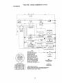
o Check wiring
See electrical wiring
diagram in the Repair Parts section.
TO REPLACE
FUSE
With engine not running, move throttle
control lever from slow to choke
position. Slowly move lever from choke
to fast position.
Check that holes "A" in governor
control lever and hole in governor plate
line-up If holes 'W' are not aligned,
loosen clamp screw and move throttle
cable until holes are aligned.. Tighten
clamp screw securely.
Governer
trol Plate
Replace with 20 amp automotive-type
plug-in fuse,, The fuse holder is located
behind the dash.
Holes "A'"
TO REMOVE
SEMBLY
TO ADJUST
HOOD
AND GRILL AS-
1, Raise hood.
2. Unsnap headlight wire connector,,
3. Stand in front of tractor, Grasp hood at
sides, tilt toward engine and lift off of
tractor,,
4,. To replace, reverse above procedure,
_Hood
/
C_
CARBURETOR
NOTE: The carburetor on this engine is low
emission, it is equipped with an idle fuel
adjusting needle with a limiter cap, which
allows some adjustment within the limits
allowed by the cap,, Do not attempt to remove
the limiter cap., The limiter cap cannot be
removed without breaking the adjusting
needle,,
The carburetor has been preset at the factory
and adjustment should not be necessary.
However, minor adjustment may be required
to compensate for differences in fuel,
temperature, altitude or load, if the carburetor
does need adjustment, proceed as follows:
In general, turning idle mixture valve in
(clockwise) decreases the supply of fuel to
the engine giving a leaner fuel/air mixture.
Turning the idle mixture valve out (counterclockwise) increases the supply of fuel to the
engine giving a richer fuel/air mixture_
IMPORTANT;
Damage to the needle valve
and the seat in carburetor may result if screw
is turned in too tight,
\
<:
_"
Governer
eadlight Wire
Connector
ENGINE
PRELIMINARY
Maintenance,
repair, or replacement
of the
emission control devices and systems, which
are being done at the customers
expense,
may be performed by any non-road engine
repair establishment
or individual Warranty
repairs must be pedormed
by an authorized
SETTING -
1
Air cleaner assembly must be assembled
to the carburetor when making carburetor
adjustments
2, Be sure the throttle control cable is
adjusted properly (see above),
engine manufacturer's service outlet.
FINAL SETTING -
TO ADJUSTTHROTTLE
I,
CONTROL
CABLE
The throttle control has been preset at the
factory and adjustment should not be
necessary. Check adjustment as described
below before loosening cable. If adjustment
is necessary, proceed as follows:
25
Start engine and allow to warm for five
minutes, Make final adjustments with
engine running and shift/motion control
lever in neutral (N) position,
2.
Move throttle control lever to slow
position. With finger, rotate and hold
throttle lever against idle speed screw,
Turn idle speed screw to attain 1750
RPM
tdfe Speed
Thr°ttle
ever
3, While still holding throttle lever against
idle speed screw, turn idle mixture valve
full travel clockwise then counterclockwise until engine runs rough_ Turn valve
to a point midway between those two
positions. Release throttle lever.
ACCELERATION
._L
Idle Mixture Valve/_
With Limiter
TEST -
4.
Move throttle control lever from slow to
fast position r If engine hesitates or dies,
turn idle mixture valve out (counterclockwise) 1t8 turn. Repeat test and continue
to adjust, if necessary, until engine
accelerates smoothly°
High speed stop is factory adjusted. Do not
adjust - damage may result.
IMPORTANT: Never tamper with the engine
governor, which is factory set for proper
engine speed. Overspeeding the engine
above the factory high speed setting can be
dangerous., if you think the engine-governed
high speed needs adjusting, contact a Sears
or other qualified service center, which has
proper equipment and experience to make
any necessary adjustments.
26
hose, or tank during storage. Also,
experiance
indicates that alcohol
blended fuels (called gasohol or using
ethanol or methanol) can attract moisture
which leads to separation and formation
of acids during storage. Acidic gas can
damage the fuel system of and engine
while in storage°
1. Drain the fuel tank,
2, Start the engine and let it run until the
fuel lines and carburetor are empty,
• Never use engine or carburetor
cleaner
products in the fuel tank or permanent
damage may occur,,
• Use fresh fuel next season,,
Immediately
prepare your tractor for
storage at the end of the season or if the
tractor will not be used for 30 days or
mo re,
CAUTION:
Never store the tractor
with gasoline in the tank inside a building
where fumes may reach an open flame or
spark, Allow the engine to cool before
storing in any enclosure.
TRACTOR
Remove mower from tractor for winter
storage, When mower is to be stored for
a period of time, clean it thoroughly,
remove all dirt, grease, leaves, etc, Store
in a clean, dry area
1, Clean entire tractor (See "CLEANING"
in the Maintenance
section of this
NOTE: Fuel stabilizer is an acceptable
alternative in minimizing
the formation of
fuel gum deposits during storage,
Add
stabilizer to gasoline in fuel tank or
storage container.
Always follow the mix
ratio found on stabilizer container.
Run
engine at least 10 minutes after adding
stabilizer to allow the stabilizer to reach
the carburetor,
Do not drain the gas tank
and carburetor if using fue! stabilizer,,
ENGINEOIL
manual).
Inspect and replace belts, if necessary
(See belt replacement
instructions
in
the Service and Adjustments
section
of this manual),,
3r Lubricate as shown in the Maintenance section of this manual°
4. Be sure that all nuts, bolts and screws
are securely fastened.
Inspect moving
parts for damage, breakage and wear.
Replace if necessary°
5. Touch up all rusted or chipped paint
surfaces; sand lightly before painting
2,
Drain oil (with engine warm) and replace
with clean engine oil. (See "ENGINE" in
the Maintenance
section of this manual),
CYLINDER(S)
t, Remove spark plug(s),
2, Pour one ounce of oil through spark
plug hole(s) into cylinder(s),
3 Turn ignition key to "START" position
for a few seconds to distribute oil.
4, Replace with new spark plug(s),
BATTER'(
• Fully charge the battery for storage.
. After a period of time in storage, battery
may require recharging.
. To help prevent corrosion and power
leakage during long periods of storage,
battery cables should be disconnected
and battery cleaned thoroughly
(see
"TO CLEAN BATTERY AND TERMINALS" in the Maintenance
section of
this manual)°
. After cleaning, leave cables disconnected and place cables where they
cannot come in contact with battery
terminals,
. If battery is removed from tractor for
storage, do not store battery directly on
concrete or damp surfaces,
OTHER
• Do not store gasoline from one season
to another,
. Replace your gasoline can if your can
starts to rust. Rust andfor dirt in your
gasoline will cause problems°
• If possible, store your tractor indoors
and cover it to give protection from dust
and dirt,
• Cover your tractor with a suitable
protective cover that does not retain
moisture,
Do not use plastic. Plastic
cannot breathe which allows condensation to form and will cause your
tractor to rust.
IMPORTANT:
Never cover tractor while
ENGINE
FUEL SYSTEM
IMPORTANT:
It is important to prevent
gum deposites from forming in essential
fuel system parts such as carburetor, fue!
engine
27
and exhaust
areas
are still warm.
TROUBLESHOOTING
CHART
PROBLEM
Wilt not start
Hard to start
CAUSE
CORRECTION
1, Out of fuel.
2. Engine not "CHOKED"
properly.
3_ Engine flooded.
1
Fill fuel tank.
2., See "TO START ENGINE"
4,
5o
6.
7
4o
5.
6.
17,
Bad spark plug,,
Dirty air filter:,
Dirty fuel filter,
Water in fuel
8., Loose or damaged wiring.
9. Carburetor out of adjustment,
8o
9..
I0, Engine valves out of
adjustment.
I0.
I_, Dirty air filter.
2o Bad spark plug.
3, Weak or dead battery.,
,
Dirty fuel filter.
5. Stale or dirty fuel,
Loose or damaged wiring
7, Carburetor out of adjustment.
6_
,
Engine will not
turn over
Engine valves
adjustment.
out of
Clutchtbrake
pedal not
depressed.
2, Attachment
clutch is
engaged,
3, Weak or dead battery.
1.
4,
Blown fuse.
Corroded battery terminals,
6. Loose or damaged wiring.
7. Faulty ignition switch.
5_
Engine clicks but
will not start
3,
8. Faulty solenoid
or starten
9.
Faulty operator
switch(es).
presence
1.
2,,
3.
4,
Weak or dead battery.
Corroded battery terminals.,
Loose or damaged wiring,,
Faulty solenoid or starten
28
in Operation section°
Wait several minutes
before attempting to starL
Replace spark plug,
Cleanfreplace
air filter.,
Replace fuel filter,
Drain fuel tank and
carburetor, refill tank with
fresh gasoline and replace
fuel filter_
Check all wiring.
See "To Adjust Carburetor"
in Service Adjustments
section,
Contact a Sears or other
qualified service centen
Clean/replace
air filter.
Replace spark plugo
34 Recharge
or replace
battery.,
4, Replace fuel filter°
5. Drain fuel tank and refill
with fresh gasoline.
& Check al! wiring,
7. See "To Adjust Carburetor"
in Service Adjustments
section_,
8. Contact a Sears or other
qualified service center°
,
2,.
I., Depress clutch/brake
pedal,
2. Disengage
attachment
clutch,,
3. Recharge or replace
battery_
4,, Replace fuse,
5. Clean battery terminals,
6, Check all wiring,
7_ Check/replace
ignition
switch,
8., Checklreptace
solenoid or
starter.
9, Contact a Sears or other
qualified service center,,
1.
2.
3,
4_
Recharge or replace battery,
Clean battery terminals.
Check all wiring,
Checklrepface
solenoid or
starter.
TROUBLESHOOTING
PROBLEM
Loss of power
CHART
CAUSE
CORRECTION
1. Cutting too much grassttoo
fasL,
2, Throttle in "CHOKE"
position.
3, Build-up of grass, leaves
and trash under mower_
4_ Dirty air filter,
5,, Low oil level/dirty oil,
6. Faulty spark plug
7_ Dirty fuel filter,,
8, Stale or dirty fuel
9, Water
in fuel
10,Spark
plug wire loose,,
t 1, Dirty engine air screen/fins_
12. Dirtylclogged
muffler.
13, Loose or damaged wiring,
14,.Carburetor
out of
adjustment.,
15, Engine valves out of
adjustmenL
Excessive
vibration
1. Worn, bent or loose blade,
2, Bent blade mandrel.
3_ Loosetdamaged
part(s).
Enginecontinues
to run
l r Faulty operator-safety
presence control system,,
when operator
leaves seat with
with attachment
clutch engaged
Poor cut - uneven
,.
Worn,
bent or loose blade,
2 Mower deck not level,
3_ Buildup of grass, leaves,
and trash under mower,
_4. Bent blade mandrel,
5. Clogged mower deck vent
holes from buildup of
grass, leaves, and trash
around mandrels.
29
I,, Set in "Higher Cut" position/
reduce speed,
2_ Adjust throttle control,,
3,
Clean underside of mower
housing,
4. Cleantreplace
air filter:,
5, Check oil leveifchange
oii_
6. Clean and regap or change
spark plug.
7. Replace fuel filter.
8, Drain fuel tank and refill with
fresh gasoline_
9_ Drain fue! tank and carbure
tor, refill tank with fresh
gasoline and replace fuel
filter_
t0oConnect
and tighten spark
plug wire°
l1_Clean engine air screenlfins,,
12,Cleanlreplace
muffler
13, Check all wiring,,
14.See "To Adjust Carburetor"
in Service Adjustments
section.
15,, Contact a Sears or other
qualified
service
center.
1. Replace blade.
Tighten blade boll
2. Replace blade mandrel,
3. Tighten loose part(s).
Replace damaged pads.
Check wiring, switches
and
connections,
If not
contact a Sears or other'
qualified service center,
1. Replace blade
Tighten
blade boll
2. Level mower deck
3_ Clean underside of mower
housing
4 Replace blade mandrel,,
5, Clean around mandrels to
open vent holes,
TROUBLESHOOTING
CHART
PROBLEM
Mower blades
not rotate
CAUSE
will
Poor grass
discharge
CORRECTION
1, Obstruction
in clutch
mechanism,
2, Worn/damaged
mower
drive belt.
3, Frozen idler pulley.,
4. Frozen blade mandrel.
1, Remove
obstruction,
2,
mower
1o Engine
1. Place throttle
speed
2. Travel speed
3, Wet grass.
too slow,
too fast,
4.. Mower deck not level,,
5, Lowtuneven
tire air
pressure.
6. Worn, bent or loose blade.
7,, Buildup of grass, leaves
and trash under mower°
& Mower drive belt worn,.
9, Blades improperly
installed_
10. Improper
blades
used.
11 .Clogged mower deck vent
holes from buildup of grass,
leaves, and trash around
mandrels,,
Headlight(s)
not
working
(if so equipped)
Battery will not
charge
1,, Switch
3. Replace
4o Replace
5,
5_ Replace
I,. Bad battery cell(s),,
2. Poor cable connections,,
4.
'1.
Faulty regulator
(if so equipped).,
Faulty alternator,,
30
control
in
Turn switch "ON".
Replace bulb(s),
Check/replace
light switch,
Check wiring and connec
tions,,
fuse,,
1. Replace battery
2,, Check/clean
all connec
tions.
3. Replace regulator,
4.
Engine throttle control not
set at "SLOW" position
for 30 seconds before
stopping engine.
idler pulley.
blade mandrel.
"FAST" position°
Shift to slower speed.
Allow grass to dry before
mowing.
4, Level mower deck.
5 Check tires for proper air
pressure°
6 Repfacetsharpen
blade.
Tighten blade bolt,,
7_ Clean underside of mower
housing,
8. Replace mower drive belto
9, Reinstall blades sharp edge
down
10, Replace with blades listed
in this manual.
t loClean around mandrels to
open vent holes,
1.
2,
3
4,
Blown fuse
drive belt
2,
3
2. Bulb(s) burned out.
3,, Faulty light switch.
4,, Loose or damaged wiring,,
3,
Engine "backfires"
whenturning
engine "OFF"
is "OFF".
Replace
.
Replace
alternator,
Move throttle control to
"SLOW" position and allow
to idle for 30 seconds before
stopping
engine.
TRACTOR
-- MODEL
NUMBER
917.271731
SCHEMATIC
BATTERY
I
RF..D
I
TN_
FUSE
RED
I
STARTER
DLACK
',©
,,
___)G
,, ,O-F_
Wftl'_E
CLUTCH! BRAKE
(PEDAL UP)
A1(
WHITF.
IGNITION
SWtTCH
_LACK (CLUTCH OFF
GROUNDING
CONNECTOR
-€
)J '_)
(OPTIONAL)
BL_CK A
IGNITION
'-I
UNIT
SPARK
L__
_
PLUG _
_J
GAP
I
(2 PLUGS ON
TWIN CYL. ENGINES)
CHARG_tIG 5Y'_TEM ,DUTPUT
.1AM_ 0C @ 3_l;rJRP_
20 V_LTS AC _,i_
J,@ 3tJ00 I'_ IJE
II_HAr_GIt_G _,YST_M DI._CI3N'N EC TEll.)
I
RE_
FUEL SHUT-OFFSOLENOID
(IF SO EQUIPPED)
LIGHT_N_ ,Sy_T_OU'iPUT
OIb%NG£
I .........
i"3|I_DF
I
I
OFF
M÷G÷A1
NONE
B+A1
A2*L
RUN
B+A!
START
_ + ,S + At
:
NONE
NONE
AC
_w_t_ @
3_00
RF_,t
{_IGHTS
O
NON-REMOVABLE
CONNECTIONS
REMOVABLE
CONNECTIONS
WIRING INSULATED CLIPS
NOTE: IF WIRING INSULATED CLIPS WERE REMOVED FOR
SERVICING OF UNIT. THEY SHOULD BE REPLACED TO
PROPERLY SECURE YOUR WIRING
31
!
O_F)
HEADLIGHTS
©
IGNITION SWITCH
PosiTioNcIRCUIT"MAKE"
RUNfLIGHT
ALTERNATOR
,_
_ _ '__,',
T4 VO_.I'S
NOTE
YOUR TRACTOR IS
EQUIPPED WITH A SPECIAL
ALTERNATOR SYSTEM.
THE LIGHTS ARE NOT
CONNECTED TO THE
BATTERY, BUT HAVE THEIR
OWN ELECTRICAL SOURCE
BECAUSE OF THIS, THE
BRIGHTNESS OF THE LIGHTS
WILL CHANGE WITH ENGINE
SPEED. AT IDLE THE LIGHTS
WILL DIM. AS THE ENGINE IS
SPEEDED UP, THE LIGHTS
WILL BECOME THEIR BRIGHTEST
I
/-;
TRACTOR
- - MODEL NUMBER
917.271731
ELECTRICAL
22
I
I
I
I
I
i
32
TRACTOR
- - MODEL
NUMBER
917.271731
ELECTRICAL
KEY
NO.
PART
NO,
DESCRIPTION
t
2
8
t5
2t
22
24
25
26
27
28
29
30
33
40
4t
42
43
45
52
144925
74760412
156417
153664
166182
4152J
4799J
146147
175158
73510400
4207J
t21305X
175566
140403
170217
71110408
131563
175141
12!433X
141940
Battery
Bolt Hex Hd ti4-20unc x 3/4
Case Battery
Switch, interlock
Harness Asm Light Wt4 t52j
Bulb Light #1156
Cabte Battery 6 Gat 1" red
Cabte Battery 6 Ga w116 wire red
Fuse 20 AMP
Nut Keps Hex 1/4-20 Unc
Cable Ground 6 Ga 12" black
Switch Plunger
Switch Ign
Key Ign
Harness tgn
Bolt Blk, Fin Hex 1t4-20 Uncx 1t2
CoverTerminal Red
Solenoid
Ammeter Rectangular 6 Amp
Protection Wire Loop
NOTE: All component dimensions given in U S inches
1 inch = 25 4 mm
33
TRACTOR -- MODEL
CHASSIS AND ENCLOSURES
NUMBER
917.271731
2g
2B
t2
31
2O8
74
34
TRACTOR - - MODEL
CHASSIS AND ENCLOSURES
NUMBER
917.271731
KEY
Nee
PART
NOr
DESCRIPTION
t
2
3
5
9
10
11
12
13
14
t7
18
25
26
28
29
30
31
37
38
51
52
53
54
55
57
60
64
74
1t4
t t5
142
t43
144
145
159
206
207
208
21 t
2t2
--
174619
176554
17060612
155272
!68337X013
STD5337t0
155927
145660
I72107X010
17490608
144983X558
126938X
19131312
STD541437
156725X558
!55217X599
t64919X558
139976
17490508
169834
73800400
19091416
145201
161464
'145202
STD522507
72140606
154798
STD541437
158112
17060620
I65867
154966
154207
156524
155123X428
170165
17670508
17670608
145212
165919
5479J
Chassis
Drawbar
Screw 3/8-I6 x 3/4
Bumper HoodlDash
Dash
Bolt, Carriage 318-16 x 1
Panel, Dash, LH
Clip Tinnerman Grille P/L
Panel, Dash, RH
Screw Thdrol 3t8-!6 x 1t2
HoodAssembly
Bumper Hood
Washer 13132x 13116x 12 Gauge
Nut
Grille wlLens Asm
Lens, Grille
FendlFtrest
Bracket, Fender Support
Screw Thdrof 5f16-I8 x 112
Pivot Bracket Assembly, Rear
Nut Lock wllnsert 114-20 UNC
Washer 9t32 x 7/8 x t6 Ga,
Bracket Grille Pickoff LH
Screw Hex Wshd 8-t8 x 7t8
Bracke{ Grille Pickoff RH
Bolt, Fin Hex 114-20 UNC x 75
Bolt Rdhd Sqnk 318-t6 UNC x 3t4
Dash LowerSTLT
NutCrownlock 318-16 UNC
Keeper Belt Rear Lh Stl P930
Screw 318-16 x t-114
Plale Reinforcement STLT
Bracket Swaybar Chassis
Bracket Pnt Foolrest STLT
Rod Pivot ChassisfHood
Cupholder Silt Black
Bolt Shoulder 5/16-t8 TT
Screw Thdrol 5t16-18 x 112Tytt
Screw Thdrol 3t8-16 × 1/2
Nut Hex Flange Lock
insert Lens Refleclive
Plug, Button
NOTE: Aff component dimensions given in U S inches
t inch = 25,4 mm
35
GROUND DRtVE
TRACTOR..
MODEL NUMBER
917.271731
26
36
TRACTOR
- - MODEL
NUMBER
917.271731
GROUND DRIVE
KEY
NO.
PART
NO,
I
........
2
3
4
5
6
8
I0
11
I3
!4
16
t8
19
21
22
24
25
26
27
28
29
30
32
34
35
36
37
38
39
40
41
42
47
48
49
50
51
52
53
55
56
57
59
61
146682
t23666X
12000028
121520X
17060512
165866
ST0561210
105701X
74550412
10040400
STD541431
STD523710
STD54t437
I06933X
130804
STD541237
106888X
ST0551037
ST0561210
175765
71673
169592
ST0523107
175578
120183X
STD551062
ST057t8!0
165936
ST0523727
175461
175556
19t31312
127783
154407
123205X
STD523715
STD54t437
STD541431
I05710X
t05709X
17060616
130801
169691
17060612
KEY PART
NO. NO,
DESCRIPTION
62
63
64
65
66
70
74
75
76
77
78
79
80
8!
82
83
84
85
89
90
96
112
113
116
120
145
150
15t
156
158
159
161
162
163
164
165
166
t68
t69
t70
197
198
202
212
Cover, Pedal
Pulley, Engine
Bolt, Hex 7/16-20 x 4 Grade 5
Washer
Keeper, Belt, Engine, Fool Proof
Guide, Mower Drive Belt, RH.
Spacer, Axle
Washer 25132 x 1-1t4 x 16 Ga
E-Ring
Key, Square 2 0 x .1845t1865
Washer 25/32 x t-5/8 x 16 Ga
Key Woodruff
Arm, Shift
Shaft Asm Cross Tapered 650 20
Spring, Torsion
Washer 17132x 314x 16 Ga
Link Transaxle
Nut, Nylock
Console, Shift, STLT
Nut, Self-Thding, Wsh Hd 1/4
Retainer Spring 1"
Washer 9132 x 3f4 x 10 Ga
Strap Torque 90 Degrees
Bolt Rdhd Sqneck 3t8-16 x 1
Nut Lock Fig 318-16
Bolt, Hex Flghd 5!16_18 Gr, 5
Spacer Relainer
Washer 13132 x 2 x 10 Ga,
Washer Srrted 5t161D x 1 125
Bracket Shift Mount
Hub Tapered Flange Shift Lt
Bolt Rdhd Sqnk II4-20 x 314Gr 5
Nut Crowniock 114-20 Uric
Bolt Hex Fin 114-20Unc x 1 Gr 5
Washer 5f8 x .281 x t0 Ga
Bracket Pivot Lever
Screw 5116-18 x 5t8
Bolt Shoulder 5116-18 x 56 t
Plale Fastening Lt
Keeper Belt Transaxle Gear
Nyliner Snap-ln
Washer Nyliner
Bolt Carr. SH 318-'16x I-3/4 Gr,, 5
Nut Hex Flange Lock
DESCRIPTION
Transaxle (See Breakdown)
Peerless 206-545C
Spring, Return, Brake
Pulley, Transaxle
Ring, Retainer
Strap, Torque
Screw 5t16-t8 x 314
Rod Shifter Fender STLT
Pin, Co_ter
Washer, Shift Plate
Bolt 1/4-28 UNF W/Patch Gr 8
Washer Lock Hvy Helical
Nut Lock Hx Wlins 5116-t8 x Gr.5
Bolt Fin Hex 3t8-16UNC x I Gr 5
Nut
Knob
Rod. Brake
Nut
Spring, Brake Rod
Washer
Pin
Rod, Parking Brake
Cap, Parking Brake
Bracket, Transaxle
Bolt
Shaft Assembly, Foot Pedal Nibbed
Bearing, Nylon
Washer
RollPin
Pulley, Composite, Flat
Bolt
Spacer, Split .395 x 59
Keeper, Belt, Idler
Washer 13132x 13116x 12Ga_
Pulley, Idler, V-Groove, Plastic
Bellcrank Clutch Grnd Dry Slt
Retainer, Bell
Bolt
Nut Crown Lock 3/8-16 UNC
Nut Grown Lock 5/16-18 UNC
Link, Clutch
Spring. Clutch Return
Screw 3t8-16 x 1.0
V-Belt, Ground Drive
Keeper, Bell, Center Span
Screw 3!8-16 x 314
8883R
175410
71170764
STD551143
154778
134683
137057
121749X
STD581075
123583X
121748X
STD580025
145090
165592
165711
19171216
166231
150360
158391X428
124346X
STD624003
19091210
127285X
72140608
73900600
74490540
175456
19133210
166002
165589
165494
72140406
73680400
74780416
19091010
165623
166860
165492
165580
173898
169613
169593
72110614
145212
NOTE: All component dimensions given in U S, inches
1 inch = 25 4 mm
37
TRACTOR - - MODEL NUMBER 917.271731
STEERINGASSEMBLY
,':]:_-_8,
, ....... L......;I_,
38
TRACTOR
STEERING ASSEMBLY
KEY
NOo
I
2
3
4
5
6
7
8
9
t0
11
t3
t5
17
26
28
29
30
32
36
37
38
39
40
41
42
43
44
46
47
51
54
63
65
67
68
71
82
85
88
91
- - MODEL
PART
NOo
139768
154427
169840
169839
6266H
t21748X
19272016
12000029
3366R
175121
STD551!37
136516
145212
177876
126847X
19131416
17060612
STD561210
130465
155099
152927
139769
19133812
STD541537
!0071tL
t45054X428
I21749X
153720
121232X
6855M
STD54143t
74760520
STD523710
160367
72140618
169827
175146
169835
133835
175118
175553
NUMBER
917.27173t
DESCRIPTION
Steering Wheel
Axle Assembly STMP Dropped STL
Spindle Assembly, L,H
Spindle Assembly, RH.
Bearing, Race, Thrust, Hardened
Washer 25132 x 1-5t8 x t6 Gauge
Washer 27/32 x lqt4 x t6 Gauge
Ring, Kfip
Bearing, Steering Column
Dragfink
Washer, Lock
Spacer Bearing Axle Front
Nut, Hex Flange Lock
Shaft Assembly, Steering
Bushing, Link, Drag
Washer 13132x 7/8 x !6 Gauge
Screw 318-t6 x 3/4
Pin Cotter
Rod, Tie
Bushing, Steering
Screw
Insert, Steering Wheel
Washer 13t32 x 2-3t8 x 12 Gauge
Nut Lock Center 318-24 Unf
Adaptor, Steering Wheel
Boot, Steering Shaft
Washer 25132 x t-1/4 x t6 Gauge
Extension Shaft Steering LRoLT
Cap, Spindle
Fitting, Grease
Nut Lock Hex w/Ins. 5116-18 UNC
Bolt Fin Hex 5It6-18 UNC x 1-tf4
Bolt, Fin Hex 3t8-16 UNC x 1 Gr5
Spacer Brace Axle
Bolt RDHD Sqnk 3/8-16 x 2-1t4
Axle, Brace
Steering Asm
Bracket Susp Chassis Front
Fastener Christmas Tree
Bolt Shoulder 7ft6-20
Clip Steering
NOTE: All component dimensions given in U S inches
1 inch = 254 mm
39
TRACTOR
- - MODEL NUMBER
917.271731
ENGINE
2
t
13 i
81
4
i
14
78
33
37
33
29
\
OPTIONAL
Spark
23
EQUIPMENT
Arrester
4O
TRACTOR
- - MODEL
NUMBER
917.271731
ENGINE
KEY
NO
PART
NOo
1
2
170545
17720410
3
4
13
14
16
23
29
31
32
33
37
38
40
44
45
46
62
72
78
8I
137352
165291
148456
STD55t231
169837
137180
109202X
158990
123487X
137040
148315
124028X
17670412
17000612
19091416
STD55tt31
71070512
17060620
73510400
DESCRIPTION
Control, Throttle
Screw, Hex Head, Thread Cutting
114-20x 5t8
Engine, (See Breakdown)
Briggs Model 311707-0125-E t
Muffler
Gasket
Tube Oil Drain Easy
Washer
Shield BrntDbr Guard
Arrestor, Spark
Tank, Fuel
Cap Assembly, Fuel Sears, Vented
Clamp, Hose
Line, Fuel
Plug Oil Drain Easy
Bushing, Snap, Fuel Line
Screw, He× Washer Head, Thd, Roll 1t4-20 x 3t4
Screw Hexwsh Thdr 3t8-16 x 314
Washer 9/32 x 7t8 x 16 Gauge
Washer, Lock
Screw Hex Hd Cap 5116-18 x 3/4
Screw 318-16 x 1-1f4
Nut Keps Hex 114-20 Unc
NOTE: All component dimensions given in U S inches
t inch = 25 4 mm
41
TRACTOR
- - MODEL NUMBER
917.271731
SEAT ASSEMBLY
l
10
I
I
I
I
I
t
!
÷
KEY PART
NO. NOo
DESCRIPTION
1
2
3
4
5
6
7
8
9
t0
tt
12
Seat
Bracket Pnt Pivot Seat (btk)
Bolt Fin Hex 316-16unc X t
Washer !3f32 X 3t4X t0 Ga
Clip Push In Hinged
Nut Hex Lock wllns 318-t6 Unc
Spring Seat Cprsn 2 250 BIk Zi
Screw 3!8-16 X t
Washer 13t32 X 1 X 14 Ga
Pan Pnt Seat
Knob Sea! Adj Wingnut
Bracket Pnt Mounting Switch
140123
140551
71110616
19131610
145006
STD541437
124181X
17000616
19131614
174894
166369
121246X
KEY
NO_
13
14
15
16
17
21
22
24
25
PART
NO.
121248X
7205O412
134300
I21250X
123976X
171852
STD541431
19171912
t27018X
DESCRIPTION
Bushing Snap BIk Ny! 50 Id
Bolt Rdhd Sht Nk 114-20xt-1t2
Spacer Split 28 X 96 Zinc
Spring Cprsn I 27 BIk Pnt
Nut Lock 114Lge Fig Gr 5 Zinc
Bolt Shoulder 5116-18 Unc-2A
Nut Hex Lock wtlns 5/16-18
Washer 17132X I-3t16 X12Ga
Bolt Shoulder 5f16-18 X 62
NOTE: All component dimensions given in U S inches
1 Inch = 25 4 mm
42
TRACTOR
- - MODEL NUMBER
917.271731
DECALS
t3
6
4
3
2
!3
10
7
20
\
8
12
t4
KEY
NO.
PART
Nee
DESCRIPTION
t
2
3
4
5
6
7
8
9
10
156368
171760
171696
171697
176680
133644
177253
172331
163204
156439
Decal, Oper Instr
Decal, Replacement
Decal, Hood, R H.
Decal, Hood, L H
Decal, HP Engine
Decal, Customer Maintenance
Decal, Hood Side
Decal, Mower Heavy Duty 12 Ga
Decal, Fender, Craftsman
Decal, Fender Danger
WHEELS
&TIRES
5,B
4,10
11
KEY PART
NO, NO,
DESCRIPTION
12
I3
14
20
---_
---
Decal, V-Belt Drive Schematic
Decal Lower Dash
Decal, V-Belt Schematic
Decal Battery DngdPsn Eng
Decal Lift Handle
Pad Footrest LH STLT
Pad Footrest RH STLT
Owner's Manual, English
Owner's Manual, Spanish
146046
177255
160396
149516
138311
165800X428
165799X428
178058
178059
KEY PART
NO. NO.
DESCRIPTION
t
2
3
4
5
6
7
8
9
10
1t
--
Cap Value Tire
Stem Value
Tire F Ts I5 X 6 0 - 6 Service
Tube Inner Front #35060
Rim Asm 6"front White Service
Fitting Grease
Bearing Flange
Rim Asm 8"rear Whtte Service
Tire R Ts 20 X 10-8 Service
Tube Rear 9 5 X 8 Service
Cap Axle Btk 1 50 X 1 00
Sealant, Tire (t0 oz. tube)
59192
65139
106222X
59904
106732X427
278H
9040H
106108X427
122082X
7152J
104757X428
'144334
NOTE: All component dimensions given in U,S inches
1inch = 254 mm
43
TRACTOR - - MODEL NUMBER 9t7.271731
LIFTASSEMBLY
!
/
5
3
13
2
6
11
5
12
13
19
2O
13
L
32
19
15
13 _
32
44
TRACTOR
- - MODEL
NUMBER
917.271731
LIFT ASSEMBLY
KEY
NOo
PART
NO_
DESCRIPTION
I
2
3
4
5
6
7
8
11
12
13
15
16
17
18
t9
20
31
32
159460
159471
105767X
12000002
192I 1621
120t83X
125631X
122365X
139865
139866
STD624008
173288
73350800
130171
73800800
139868
163552
169865
73540600
Washer Asm inner Spring W/Plunger
Shaft Asm, Lift
Pin Groove
E Ring#5 t33-62
Washer 2t132 x 1x 21 Ga,
Bearing Nylong
Grip Handle Fluted
Button Plunger Read
Link Asm Lift LH
Link Asm Lift R,H,
RetainerSpring
Link Front
Nut Jam Hex 1/2-13 Unc
Trunnion BIk Zinc
Nut Lock wlWsh 112-t3 Unc
Arm Suspension Mower
Retainer Spring
Bearing, Pvt Lift
Nut Crewnlock 3t8-24
NOTE: All component dimensions given in U S inches
1 inch= 25 4 mm
45
TRACTOR
MOWER
- - MODEL NUMBER
917.271731
DECK
34
27
46
TRACTOR
MOWER
KEY
NO,
PART
NO.
1
2
3
165892
STD533107
138017
4
5
6
8
9
10
11
13
t4
15
t6
!8
19
20
21
22
23
24
25
26
27
28
29
30
3t
32
33
34
36
37
40
44
45
46
48
49
50
5't
52
53
54
55
56
59
67
68
-- MODEL NUMBER
917.271731
DECK
KEY
NOo
DESCRIPTION
Mower Housing
Bolt
Bracket Assembly,Sway Bar,
Front
165460
Bracket Sway Bar 38t42"
STD624008 RetainerSpring
130832
Arm, Suspension,Rear
850857
Bolt, Hex 318-24 x t 25 Gr 8
STD551t37
Washer, Lock
140296
Washer, Hardened
134149
Blade,Mulching
137645
Shaft Assembly, Mandrel, Vented
(incl. Key Number 6)
128774
Housing, Mandret, Vented
t10485X
Bearing, Ball,Mandrel
174493
Stripper, MowerDeck
72140505
Bolt, Carriage 5f16-18 x 5t8
132827
Bolt, Shoufder
159770
Baffte, Vortex
STD541431 Nut, Crownlock 5f 16-18 UNC
134753
Stiffener Bracket
131267
Bracket, Deflector
105304X
Cap, Sleeve
123713X
Spring, Torsion, Deflector
110452X
Nut, Push
130968X428 Shield, DefIector
1911't016
Washer 11132x 5t8 x 16 Ga
131491
Rod,Hinge
157722
Screw Thdrot RollingWsh Hd
129963
Washer, Spacer
153535
Pulley, Mandret
137266
Nut, Top!ock0 Flanged
STD533717 Bolt
131494
Pulley, Idler, Flat
19131316
Washer 13132x 13116x 16 Ga.
STD541437 Nut, Crownlock 3tB-16 UNC
140088
Guard, Mandrel, LH
STD624003 Retainer
137729
Screw, Thd Roll ti4-20 x 5f8
133944
Washer, Hardened
174284
RoIler Assembly,Cam Fotlower
131340
Bolt, Shoulder #10-24 Grade 5
STD541410 Locknut
139888
Bolt, Shoulder 5tt6-18 UNC
131845
Arm Assembly, Pad, Brake
133943
Washer, Hardened
155046
Arm, Idler
165723
Spacer, Retainer
141043
Guard, Tuv Idler (94)
Knob Custom Oval
149846
144959
V-Belt
PART
NO,
92
101
t02
103
t04
105
I06
11t
112
1'13
1t4
115
1t6
1t7
118
119
12I
129
t30
131
142
t43
144
t45
146
147
t48
t49
150
t51
t52
'153
!54
t55
156
157
158
i59
- -
STD54t437
136420
71081010
19061216
STD551110
160793
2029J
155197
155t98
I70605 t4
73510500
72110504
4698H
165746
73930600
19121414
143723
19131312
STD523710
STD5337t0
165890
157109
158634
165888
171977
131335
169022
165898
19091216
'169670
169676
169674
169675
169671
169672
169669
17720410
STD533717
130794
- -
169583
NOTE: AI! component
1 Inch = 25 4 mm
47
DESCRIPTION
Locknut, Hex WlWsh 318-16 UNC
Cover Mulching 42" Black
Screw Truss Hd Phil t0-24 x518
Washer#10
Washer Lock
Latch Asm Bagger
NutWeld
Bracket Gauge, Wheet LH
Bracket, Gauge, Wheel RH
Screw 5t16-t8
Nut, Hex Keps 51t6-18 UNC
Bolt, Carriage 5/16 UNC x 1t2
Bolt, Shoulder
Wheel, Gauge
Nut, Crownlock 3!8-1
Washer 13f32 x 718 x 14 Ga,
Bracket
Washer !3/32 x 13116x 12 Ga,
Bolt, Fin Hex 3t8-t6 UNC x 1 Gr 5
Bolt Rdhd Sqnk 318-16 UNC x 1
Arm Spring Brake Mower
Bracket Arm Idler 42"
Keeper Beit 42" Clutch Cable
Pulley idler Flat
Bolt Carraige fdler
Spring Extension
Spring Return idler
Retainer Spring Yellow Zinc
Washer 9t32 x 3/4 x t6 Ga,
Bracket Clutch
Cable Clutch 42"
Washer flat 318" Type B
Spring Retainer
Spring Retention Lever
Spacer
Rod Clutch
Screw Hex Thd Cut 1t4_20x 5t8
Bolt Rdhd Sqn 3f8-t6 Unc x 1-3/4
Mandrel Assembly (Includes Key
Numbers 8-t0, 13-15, 3t and 32)
Mower Deck, Complete (Std deckorder separately mulcher plate
components key nos 101-106)
dimensions
given in U ,S inches
TRACTOR - - MODEL NUMBER 917.271731
PEERLESS TRANSAXLE - - MODEL NUMBER 206-545C
67
5
150
B
70 6A
83
/
35
B2
t8
/
47
4
t3
59
15
3B
44
f5
4_
7Q
MODEL _nd SERIAL
NUMBERS HERE
42
48
TRACTOR - - MODEL NUMBER 917.271731
PEERLESS TRANSAXLE - - MODEL NUMBER 206-545C
KEY
NO,
PART
NO,
1
2
3
4
5
6
6A
7
8
8A
9
10
t1
12
13
t4
t5
17
!8
20
21
22
25
25A
26
27
28
29
29A
29B
29C
30
3I
772t47
780086A
770128
776395
776409
778364
778369
778330
792180
792047
784352
784378
778334
778309
778368
778368
778370
786188
786102
792077A
792078
792079
792073A
792177
792125
792035
788040
780072
780160
780051
780199
780108
780001
31A
32
34
35
35A
36
37
38
39
40
780195
788083
780194
780193
780197
790075
790007
799021
786026
792076A
DESCRIPTION
TransaxreCover
Needle Bearing 5t8"
Transaxle Case
Countershaft
Output Shaft
Spur Gear (38 teeth)
Spur Gear (t5 teeth)
Spur Gear (t I teeth)
Shift Key
Woodruff Key #9
Shift Collar
Shift Rod & Fork
Bevel Gear (30 teeth)
Input Bevel Pinion (13 teeth)
Bevel Gear (13 teeth)(Include t4)
Bevel Pinion (13 teeth)0nclude !3)
Ring Gear (43 teeth)
Drive Pin
Spacer 1.I30 X 695
Bail 5/16 " dia
Set Screw 3t8 - t6 x 3f8"
Spring ,310 OD x 625 L
Screw 1!4 - 20 x lqf4"
Screw 114-20x 1-3!8"
Retaining Ring (pkg of 2)
Retaining Ring
Retaining Ring
Thrust Washer 627 ID x031W
Thrust Washer 762 tD x031W
Thrust Washer .762 lD x.O31W
Anti-RotationWasher 632
Cup Washer 1..127 ID x .032W
Flat Washer 750 ID x 056W
(Use As Needed)
FfatWasher 750 iD x .062W
Oil Seal 5f8"
Bushing .563
Flanged Bushing 5 f 8" ID
FiangedBushing.751
Brake Disk
Brake Pad Plate
Brake Pad (pkg ef 2)
Dowel Pin
Fiat Washer .312 1Dx 059W
49
KEY
NOo
PART
NO.
4IA
42
42A
43
44
45
46
47
48
49
50
51
52
53
54
56
57
58
59
60
61
65
66
67
69
70
71
718
76
77
79
82
83
85
87
150
157
180
900
790079
792073A
792085A
792075
790025
786066
786086
774690
774691
778356
778338
778354
778352
778350
778346
778355
778337
778353
778351
778349
778345
780189
776422
776396
792170
786187
788069
788092
780090
788078A
792144
778333
778338
792 t54
788089A
788093A
788088A
730229A
794712
DESCRIPTION
Brake Lever
Screw !14 - 20 x 1-1 t4"
Screw tt4 - 20 x 2 114"
Locknut 5 f 16 - 24
Brake Pad Holder
Spacer 2625 x 1.0
Brake Lever Bracket
Axle (11-15t 16" Long)
Axle (I6 - 1 I 2" long)
Spur Gear (29 teeth)
Spur Gear (27 teeth)
Spur Gear (23 teeth)
Spur Gear (19 teeth)
Spur Gear (16 teeth)
Spur Gear (t5 teeth)
Spur Gear ( 11 teeth)
Spur Gear (13 teeth)
Spur Gear (17 teeth)
Spur Gear (2t teeth)
Spur Gear (24 teeth)
Spur Gear (25 teelh)
Flat Washer ,563 ID x 062W
Input Shaft
Shifter & Brake Shaft
Retaining Ring
Spacer .890
Square Cut Ring
"O"Ring
Flat Washer t. 128 ID x .058W
Inverted Retaining Ring
Spring .430 OD x 5000 L
Beve_ & Spur Gear (30 & 13 teeth)
Spur Gear (27 teeth)
Oil Fill Plug
Oil Seal 91 16"
Liquid Gasket RTV Silicone
Oil Seal 314"
Gear Oil 80W90
Replacement MST-206-545C
Transaxle
NOTE: All component dimensions given in U..S inches
t inch = 25 4 mm
TRACTOR -- MODEL NUMBER 917.271731
BRIGGS ENGINE-MODELNUMBER311707,TYPE NUMBER0125_E1
REQUIRES SPECIAL TOOLS
TO INSTALL.
SEE REPAIR
INSTRUCTION
MANUAL°
_3_
71
5O
TRACTOR -- MODEL NUMBER 917.271731
BRIGGS ENGINE-MODEL NUMBER 311707, TYPE NUMBER 0125-E1
9;,t
240
176
344_i_
1' 1019 LABEL KIT "i
I t058 OWNER'S MANUAL ,'1
267
IB6_
_
,1o+M _.-..
,
142 _
_-117
1789J,_S__
51
TRACTOR -- MODEL NUMBER 917,271731
BRtGGS ENGINE-MODEL NUMBER 311707, TYPE NUMBER 0125-E1
31o_
513_&
5_
803
,797
304i
462@ (_
579
732"-_
!
t851"_
1036 LABEL-EMISSIONS
I
37'
j
1II9_
523 _
287_
842
1005 i
75Q
524_
52
TRACTOR - - MODEL NUMBER 917.271731
BRIGGS ENGINE-MODEL NUMBER 311707, TYPE NUMBER 0125-E1
977 CARBURETOR
I21 CARBURETOR
GASKET SET
I04_
127 0
OVERHAUL KIT
276 _
987_
95
1095 VALVE GASKET SET
358 ENGINE GASKET SET
524_
883_
20_842_6_17
48
5
9
617
NIKKI
13oA
O
231A_
U
121A CARBURETOR
I
51_
9TSAt
OVERHAUL KIT
95A_
276A _)
104A_
127AO
105A_
987A_
231A_
369
977A CARBURETOR
Q_OA_
276A
947A_
53
GASKET SET
TRACTOR - - MODEL NUMBER 917.271731
BRIGGS ENGINE-MODEL NUMBER 311707, TYPE NUMBER 0125-E1
KEY
NOo
1
2
3
4
5
7
B
9
10
11
12
13
15
I6
20
22
23
24
25
PART
NO.
690t56
399265
391086
494238
690t88
692410
696126
27803
691666
691328
692226
,
.+
•
,
692406
•
692405
,
690360
690946
690136
291675
692125
693557
222698
692271
692272
Piston
S.I
Piston Assembly
Assembly (,020
(.030 O
O.S.
Ring Set-Piston (Standard)
Ring Set-Piston (010 OS)
Ring Set-Piston (.D20 O.S,)
Ring Set-Piston (D30 O.S)
27
Lock-Piston
Pin
28
Pin-Piston (Standard)
Pin-Piston (020 O.S )
29
Rod-Connecting
(Standard)
Rod-Connecting
(020 U,S,)
32
Screw (Connecting Rod)
33
Valve-Exhaust
34
Valveqntake
35
Spring-Valve (Intake)
36
Spring-Valve (Exhaust)
37
Guard-Flywheel
40
Retainer-Valve
43
Slinger-GovernortOiI
45
Tappet-Valve
46
Camshaft
48
Short Block (311707-0028-EI
Replacement
Engine)
50
690193
Manifold-Intake
51
692137.O:l:+Gasketqntake
53
690227
Stud (Carburetor)
54
691148
Screw (Intake Manifold)
73
494439
Screen-Rotating
74
691057
Screw (Rotating Screen)
75
690582
Washer (Flywheel)
78
690661
Screw (Flywheel Guard)
93
690602
O BusNng-Thrott_e
Shaft
94
498030
Kit-Idle Mixture
94A
695425
Kit-Idle Mixture
95
691636
O Screw (Throttle Valve)
95A
690718
O Screw (Throttle Valve)
98
495800
Kit-Idle Speed
9BA
695408
Kit-Idle Speed
104
690525
O Pin-Float Hinge
104A 694918
O Pin-Float Hinge
105
231855
O Valve-Float Needle
105A 694922
O Vafve-FIoat Needle
26
692273
692274
690162
692164
692166
692168
691299
498319
498320
692419
692420
692852
495856
495857
691279
691279
690456
691752
691968
690564
692421
692706
,
DESCRIPTION
Cylinder Assembly
Kit-Bushing/Seal
Seai-Oit (Magneto Side)
Sump-Engine
Head-Cylinder
Gasket-Cylinder
Head
Breather Assembly
Gasket-Breather
Screw (Breather Assembly)
Tube-Breather
Gasket-Crankcase
(015 Thick,
Std)
Gasket-Crankcase
(,005
Thick)
Gasket-Crankcase
(,009
Thick)
Screw (Cylinder Head)
Plug-Oil Drain
Crankshaft
Seal-Oil
Screw (Crankcase Cover)
Flywheel
Key-Flywheel
Piston Assembly (Standard)
Piston Assembly (010 OS)
KEY
NO.
106
t06
108A
I08B
1 t7
PART
NO.
690577
690464
692344
695419
692408
692411
695415
695416
690191
695427
690194
DESCRIPTION
O Seat-Inlet
Valve-Choke (Manual Choke)
Valve-Choke(Cho ke-A*Matic)
Valve-Choke(Nikki
Carburetor)
O Jet-Main (Standard)
Jet-Main (High Altitude)
117A
O Jet-Main (Standard)
O Jet-Main (High Altitude)
Kit-Carburetor
Overhaul
t21
t2tA
Kit-Carburetor
Overhaul
Carburetor
125
t 25A
Carburetor (Nikk O (Service with
Walbro Carburetor)
127
695005
O Plug-Welch
I27A 690727
O Plug-Welch
Valve-Throttle
130
691750
Valve-Throttle
t30A 695418
Kit-Throttle Shaft
t3t
494379
131A 695421
Kit-Throttle Shaft
t33
494381
Float-Carburetor
Float-Carburetor
t33A 694914
137
28 t165 O$ Gasket-F_oat Bowl
I37A 695426 O:t: Gasket-Float
Bowl
141
495097
Kit-Choke Shaft (Manual
Choke)
Kit-Choke Shaft (Choke-At41A 49593t
Matic)
141B 695420
Kit-Choke Shaft (Nikki)
O Nozzle-Carburetor
t42
692412
146
691639
Key-Timing
167
692297
Air Cleaner Stud Seal
176
691917
• O-Ring Seal (Air Cleaner)
185
690958
Nut (Air Cleaner Base)
Connector-Hose
tB6
692317
t87
691050
Line-Fuel (Cut to Required
Length)
t88
691693
Screw (Control Bracket)
t92
691986
Adjuster-Rocker
Arm
202
691841
Link-Mechanical
Governor
209
692208
Spring-Governor
Link-Choke
216
691840
217
695409
Spring-Choke
Return
222
694042
Bracket-Control
Control Lever-Governor
227
691374
231
691636
O Screw (Choke Valve)
23tA 690718
O Screw (Choke Valve)
232
691842
Spring-Governor
Link
238
691843
Cap-Valve
240
394358
Filter-Fuel
265
691024
Clamp-Casing
267
695134
Screw (Casing CIamp)
276
692255 05 Sealing Washer
276A 695410 05 Sealing Washer
287
691002
Screw (Dipstick Tube)
304
691399
Housing-Blower
RPM Settings:
Low Speed: t900-2100
High Speed: 3000-3200
Included in Engine Gasket Set, Key No, 358
O
Included in Carburetor Overhaul Kit, Key
No. 121and121A
Included in Carburetor Gasket Set, Key. No
977 and 977A
+
Included in Vafve Gasket Set, Key No, 1095
NOTE: All component dimensions given in US
inches 1 inch = 254 mm
54
TRACTOR-MODEL NUMBER 917.271731
BRIGGS ENGINE-MODEL NUMBER 311707, TYPE NUMBER 0125-E1
KEY
NO.
305
306
307
309
3t0
311
333
334
337
344
35B
363
369
383
404
445
462
467
474
503
505
510
513
523
524
525
544
552
562
579
601
614
6t6
617
633
634
PART
NO.
690960
690499
691003
693551
690323
497608
495859
69106t
491055
693675
690189
19203
695422
89838
69169I
496894
691261
691668
691063
691532
69'1251
693699
692024
692014
281370
69139B
692034
491986
691119
691029
95162
691620
692012
692138
695414
690801
O
634A
690802
O
635
668
691
692
697
711
718
727
729
729A
732
733
741
757
758
759
76t
783
789
789A
691909
691500
692407
690572
690372
690703
690959
490324
691335
691224
691002
691658
691284
691714
692423
691239
691096
693713
692037
695050
•
•
•
KEY
NO.
797
80I
802
803
830
842
847
851
868
871
875
B77
883
914
934
947
947A
950
950A
967
968
971
975
975A
977
977A
987
987A
996
t005
1006
10t9
I022
1023
1026
DESCRIPTION
Screw (Blower Housing)
Shield-Cylinder
Screw (Cylinder Shield)
Motor-Starter
Screw (Starter Motor)
Brush Set
Armature-Magneto
Screw (Armature Magneto)
Spark Plug
Screw (Cable Clamp)
Engine Gasket Set
Flywheel Puller
Spring-Float
Bowl
Wrench-Spark
Plug
Washer (Governor Crank)
Filter-Air Cleaner Cartridge
Washer (Brush Retainer)
Knob-Air Cleaner
Alternator
Strap-Starter
Nut (Governor Control Lever)
Drive-Starter
Clutch-Drive
Dipstick
Seal-Dipstick
Tube
Tube-Dipstick
Armature-Starter
Bushing-Governor
Lever
Bolt (Governor Control Lever)
Nut (Starter Cable)
Clamp-Hose
Pin-Cotter
Crank-Governor
O-Ring Sea! (intake Manifold)
Seal-ChokefThrottle
Shaft
Seal-Spring Assembly
(Manual Choke)
Seat-Spring Assembly
(Choke-A-Matic)
Boot-Spark Plug
Spacer
Seal-Governor
Shaft
Spring-Detent
Screw (Drive Cap)
Screw (Carburetor Shield)
Pin-Locating
Cover-Starter Drive
Clip-Wire
Clip-Wire
Screw (Starter Drive Cover)
Screw (Crankshaft Extension)
Gear=Timing
Link-Counterweight
Counterweight
Pin-Counterweight
Screw (Counterweight)
Gear-Pinion
Harness-Wiring
Harness-Wiring
1029
1034
1036
1051
1058
1090
1091
1095
1119
RPM
•
PART
NO.
593167
691429
691286
693757
691095
691870
496415
692424
690968
690969
696129
393456
692236
690960
69105B
497672
695423
691657
695407
272403
691332
692129
495933
695417
690192
695428
691326
690998
690678
695492
690452
690180
272475
692492
692003
6920!1
691751
690822
695700
691265
274789
691293
691333
690190
69I 183
Settings:
DESCRIPTION
Nut (Brush Retainer)
Cap-Drive
Cap-End
Housing-Starter
Stud (Rocker Arm)
• Dipstick/Tube Seal
Dipstick/Tube Assembly
Terminal-Spark
Plug
.+ Seaf-Valve
Bushing-Guide
Base-Air Cleaner
Wire-ConnectortAIternator
• Gasket-Exhaust
Screw (Rocker Cover)
Screw (Fan Retainer)
Solenoid-Fuel
Solenoid-Fuel
Screw-Float Bowl
Screw-Float Bowl
Filter-Pro Cleaner
Cover-Air Cleaner
Screw (Air Cleaner Base)
Bowl-Float
Bowl-Float
Set-Carburetor
Gasket
Set-Carburetor
Gasket
O Seat-Throttle
Shaft
O Seal-Throttle
Shaft
Carburetor Shield
Fan-Flywheel
Retainer-Fan
Kit-Label
.+ Gasket-Rocker
Cover
Cover-Rocker
Rod-Push (Intake)
Rod-Push (Exhaust)
Arm-Rocker
Guide-Push Rod
Label-Emissions
Retainer-Brush
Owner's Manual
Retainer-Brush
Cap-Limiter
Valve Gasket Set
Screw (Alternator)
Low Speed: 1900-2t00
High Speed: 3000-3200
in Engine Gasket Set, Key No,
included
358
(2}
included in Carburetor Overhaul Kit, Key
No. 121and121A
:l:
included in Carburetor Gasket Set, Key
No. 977 and 977A
+
included in Valve Gasket Set, Key. No.
1095
NOTE: All component dimensions given in US
inches I inch = 254 mm
55
56
57
58
SUGGESTED
GUIDE FOR SIGHTING
SLOPES FOR SAFE OPERATION
ONLY RIDE UP AND DOWN HILL,
NOT ACROSS HILL
SIGHT AND HOLD THIS LEVEL WITH
SKY LINE OR TREE.
15° MAX.
ii _ ,_
!;! _
Operate
your 15°),
Tractor
up across
and down
of slopes
(not
greater than
never
the the
face.face
Make
turns gradually to prevent tipping or toss of control. Exercise extreme
iI
caution when changing direction on slopes.
:i
II/
i: : i
i I " _"
"
i
::
_
L :,,
:
i
_
•
:
Get it fixed, at your home or ours!
For repair of major brand appliances
in your own home...
no matter who made it, no matter who sold it!
1-800-4-MY-HOME sMAnytime,
day or night
(t-800-469-4663)
wwwosears,com
To bring in products such as vacuums,
lawn equipment and electronics for repair, call for
the location of your nearest Sears Parts & Repair Center,
1..800-488-1222
Anytime, day or night
wwwosearsocom
For the replacement parts, accessories
and owner's manuals
that you need to do-it-yourself,
call Sears PartsDirectSM[
1-800-366-PART
(1-800-366-7278)
6am.-11pro,CST,
7 days a week
www.sears.com/partsdirect
To purchase
or inquire about a Sears Service
Agreement:
1-800-827=6655
7 aom,- 5 p.m, CST, Mon,Para pedir servlcio de reparaci6n a domicilio,
y pare ordenar piezas con entrega a domicilio:
1-888-SU-H O GAR s_
Sat
Au Canada pour service en fran9ais:
1-877.LE.FOYER s'_
(I_877-533-6937)
(1-888-784-6427)
© Sears, Roebuck and Co
178058
01_17_01
RH
@ Regis|ered Trademark I T_ Trademark of Sears, Roebuck and Co
@ Marca Reglstrada f TM Marca de F&brica de Sears, Roebuck and Co
Printed
in U.SAo