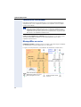
1
optiPoint Montageanleitung für Beistellgeräte, Adapter und Zubehör Installation instructions for accompanying equipment, adapters and accessories Notice de montage pour satellites, adaptateurs et accessoires Montage-instructie voor uitbreidingsterminals, toebehoren en adapters Istruzioni di montaggio per apparecchi ausiliari, adattatori ed accessori Instrucciones de montaje para aparatos auxiliares, adaptadores y accesorios Instruções de montagem para aparelhos suplementares, acessórios e adaptadores 2 optiPoint key module / optiPoint BLF / optiPoint signature module / optiPoint display module / optiPoint application module / self labelling key module optiPoint adapter 3 쮕 খ 4 Beschreibung siehe ab Æ 9 For description, see from Æ 33 onward Description : voir à partir de la page Æ 57 Omschrijving zie vanaf Æ 81 Descrizione a partire da Æ 105 Descripción a partir de Æ 129 Descrição ver a partir de Æ 154 Ø Deutsch Beistellgeräte . . . . . . . . . . . . . . . . . . . . . . . . . . . . . . . . . . . . . . . . . . . 9 optiPoint key module/optiPoint BLF. . . . . . . . . . . . . . . . . . . . . . . . . . . . . . . . . 9 optiPoint signature module . . . . . . . . . . . . . . . . . . . . . . . . . . . . . . . . . . . . . . 10 optiPoint display module/optiPoint application module . . . . . . . . . . . . . . . . . 11 optiPoint self labelling key module. . . . . . . . . . . . . . . . . . . . . . . . . . . . . . . . . 12 optiPoint acoustic adapter . . . . . . . . . . . . . . . . . . . . . . . . . . . . . . . . . . . . . . . 13 optiPoint analog adapter . . . . . . . . . . . . . . . . . . . . . . . . . . . . . . . . . . . . . . . . 14 optiPoint ISDN adapter . . . . . . . . . . . . . . . . . . . . . . . . . . . . . . . . . . . . . . . . . 15 optiPoint phone adapter. . . . . . . . . . . . . . . . . . . . . . . . . . . . . . . . . . . . . . . . . 16 optiPoint recorder adapter . . . . . . . . . . . . . . . . . . . . . . . . . . . . . . . . . . . . . . . 17 Zubehör . . . . . . . . . . . . . . . . . . . . . . . . . . . . . . . . . . . . . . . . . . . . . . . . 18 Aktive Lautsprecherbox . . . . . . . . . . . . . . . . . . . . . . . . . . . . . . . . . . . . . . . . . Beistellmikrofon . . . . . . . . . . . . . . . . . . . . . . . . . . . . . . . . . . . . . . . . . . . . . . . optiPoint Conference Kit . . . . . . . . . . . . . . . . . . . . . . . . . . . . . . . . . . . . . . . . USB-Tastatur . . . . . . . . . . . . . . . . . . . . . . . . . . . . . . . . . . . . . . . . . . . . . . . . . Wandhalterung. . . . . . . . . . . . . . . . . . . . . . . . . . . . . . . . . . . . . . . . . . . . . . . . 18 21 23 31 32 Ø English Add-on Devices . . . . . . . . . . . . . . . . . . . . . . . . . . . . . . . . . . . . . . . . . 33 optiPoint key module/optiPoint BLF. . . . . . . . . . . . . . . . . . . . . . . . . . . . . . . . optiPoint signature module . . . . . . . . . . . . . . . . . . . . . . . . . . . . . . . . . . . . . . optiPoint display module/optiPoint application module . . . . . . . . . . . . . . . . . optiPoint self labelling key module. . . . . . . . . . . . . . . . . . . . . . . . . . . . . . . . . optiPoint acoustic adapter . . . . . . . . . . . . . . . . . . . . . . . . . . . . . . . . . . . . . . . optiPoint analog adapter . . . . . . . . . . . . . . . . . . . . . . . . . . . . . . . . . . . . . . . . optiPoint ISDN Adapter . . . . . . . . . . . . . . . . . . . . . . . . . . . . . . . . . . . . . . . . . optiPoint Phone Adapter . . . . . . . . . . . . . . . . . . . . . . . . . . . . . . . . . . . . . . . . optiPoint Recorder Adapter . . . . . . . . . . . . . . . . . . . . . . . . . . . . . . . . . . . . . . 33 34 35 36 37 38 39 40 41 Accessories . . . . . . . . . . . . . . . . . . . . . . . . . . . . . . . . . . . . . . . . . . . . 42 Active Speaker . . . . . . . . . . . . . . . . . . . . . . . . . . . . . . . . . . . . . . . . . . . . . . . . Desk microphone . . . . . . . . . . . . . . . . . . . . . . . . . . . . . . . . . . . . . . . . . . . . . . optiPoint Conference Kit . . . . . . . . . . . . . . . . . . . . . . . . . . . . . . . . . . . . . . . . USB keyboard . . . . . . . . . . . . . . . . . . . . . . . . . . . . . . . . . . . . . . . . . . . . . . . . Wall Mount Unit . . . . . . . . . . . . . . . . . . . . . . . . . . . . . . . . . . . . . . . . . . . . . . . 42 45 47 55 56 5 Ø Français Satellites . . . . . . . . . . . . . . . . . . . . . . . . . . . . . . . . . . . . . . . . . . . . . . . 57 optiPoint key module/optiPoint BLF. . . . . . . . . . . . . . . . . . . . . . . . . . . . . . . . optiPoint signature module . . . . . . . . . . . . . . . . . . . . . . . . . . . . . . . . . . . . . . optiPoint display module/optiPoint application module . . . . . . . . . . . . . . . . . optiPoint self labelling key module. . . . . . . . . . . . . . . . . . . . . . . . . . . . . . . . . optiPoint acoustic adapter . . . . . . . . . . . . . . . . . . . . . . . . . . . . . . . . . . . . . . . optiPoint analog adapter . . . . . . . . . . . . . . . . . . . . . . . . . . . . . . . . . . . . . . . . optiPoint ISDN adapter . . . . . . . . . . . . . . . . . . . . . . . . . . . . . . . . . . . . . . . . . optiPoint phone adapter. . . . . . . . . . . . . . . . . . . . . . . . . . . . . . . . . . . . . . . . . optiPoint recorder adapter . . . . . . . . . . . . . . . . . . . . . . . . . . . . . . . . . . . . . . . 57 58 59 60 61 62 63 64 65 Accessoires . . . . . . . . . . . . . . . . . . . . . . . . . . . . . . . . . . . . . . . . . . . . 66 Enceinte active. . . . . . . . . . . . . . . . . . . . . . . . . . . . . . . . . . . . . . . . . . . . . . . . Microphone supplémentaire . . . . . . . . . . . . . . . . . . . . . . . . . . . . . . . . . . . . . optiPoint Conference Kit . . . . . . . . . . . . . . . . . . . . . . . . . . . . . . . . . . . . . . . . Clavier USB . . . . . . . . . . . . . . . . . . . . . . . . . . . . . . . . . . . . . . . . . . . . . . . . . . Support mural . . . . . . . . . . . . . . . . . . . . . . . . . . . . . . . . . . . . . . . . . . . . . . . . 66 69 71 79 80 Ø Nederlands Uitbreidingsterminals . . . . . . . . . . . . . . . . . . . . . . . . . . . . . . . . . . . . 81 optiPoint key module/optiPoint BLF. . . . . . . . . . . . . . . . . . . . . . . . . . . . . . . . optiPoint signature module . . . . . . . . . . . . . . . . . . . . . . . . . . . . . . . . . . . . . . optiPoint display module/optiPoint application module . . . . . . . . . . . . . . . . . optiPoint self labelling key module. . . . . . . . . . . . . . . . . . . . . . . . . . . . . . . . . optiPoint acoustic adapter . . . . . . . . . . . . . . . . . . . . . . . . . . . . . . . . . . . . . . . optiPoint analog adapter . . . . . . . . . . . . . . . . . . . . . . . . . . . . . . . . . . . . . . . . optiPoint ISDN adapter . . . . . . . . . . . . . . . . . . . . . . . . . . . . . . . . . . . . . . . . . optiPoint phone adapter. . . . . . . . . . . . . . . . . . . . . . . . . . . . . . . . . . . . . . . . . optiPoint recorder adapter . . . . . . . . . . . . . . . . . . . . . . . . . . . . . . . . . . . . . . . 81 82 83 84 85 86 87 88 89 Toebehoren . . . . . . . . . . . . . . . . . . . . . . . . . . . . . . . . . . . . . . . . . . . . 90 Actieve luidsprekerbox. . . . . . . . . . . . . . . . . . . . . . . . . . . . . . . . . . . . . . . . . . 90 Extra microfoon . . . . . . . . . . . . . . . . . . . . . . . . . . . . . . . . . . . . . . . . . . . . . . . 93 optiPoint Conference Kit . . . . . . . . . . . . . . . . . . . . . . . . . . . . . . . . . . . . . . . . 95 USB-toetsenbord . . . . . . . . . . . . . . . . . . . . . . . . . . . . . . . . . . . . . . . . . . . . . 103 Wandhouder . . . . . . . . . . . . . . . . . . . . . . . . . . . . . . . . . . . . . . . . . . . . . . . . 104 6 Ø Italiano Apparecchi ausiliari . . . . . . . . . . . . . . . . . . . . . . . . . . . . . . . . . . . . 105 optiPoint key module/optiPoint BLF. . . . . . . . . . . . . . . . . . . . . . . . . . . . . . . optiPoint signature module . . . . . . . . . . . . . . . . . . . . . . . . . . . . . . . . . . . . . optiPoint display module/optiPoint application module . . . . . . . . . . . . . . . . optiPoint self labelling key module. . . . . . . . . . . . . . . . . . . . . . . . . . . . . . . . optiPoint acoustic adapter . . . . . . . . . . . . . . . . . . . . . . . . . . . . . . . . . . . . . . optiPoint analog adapter . . . . . . . . . . . . . . . . . . . . . . . . . . . . . . . . . . . . . . . optiPoint ISDN adapter . . . . . . . . . . . . . . . . . . . . . . . . . . . . . . . . . . . . . . . . optiPoint phone adapter. . . . . . . . . . . . . . . . . . . . . . . . . . . . . . . . . . . . . . . . optiPoint recorder adapter . . . . . . . . . . . . . . . . . . . . . . . . . . . . . . . . . . . . . . 105 106 107 108 109 110 111 112 113 Accessori . . . . . . . . . . . . . . . . . . . . . . . . . . . . . . . . . . . . . . . . . . . . . 114 Altoparlante attivo . . . . . . . . . . . . . . . . . . . . . . . . . . . . . . . . . . . . . . . . . . . . Microfono esterno . . . . . . . . . . . . . . . . . . . . . . . . . . . . . . . . . . . . . . . . . . . . optiPoint Conference Kit . . . . . . . . . . . . . . . . . . . . . . . . . . . . . . . . . . . . . . . Tastiera USB . . . . . . . . . . . . . . . . . . . . . . . . . . . . . . . . . . . . . . . . . . . . . . . . Supporto per montaggio a parete . . . . . . . . . . . . . . . . . . . . . . . . . . . . . . . . 114 117 119 127 128 Ø Español Aparatos auxiliares . . . . . . . . . . . . . . . . . . . . . . . . . . . . . . . . . . . . 129 optiPoint key module/optiPoint BLF. . . . . . . . . . . . . . . . . . . . . . . . . . . . . . . optiPoint signature module . . . . . . . . . . . . . . . . . . . . . . . . . . . . . . . . . . . . . optiPoint display module/optiPoint application module . . . . . . . . . . . . . . . . optiPoint self labelling key module. . . . . . . . . . . . . . . . . . . . . . . . . . . . . . . . optiPoint acoustic adapter . . . . . . . . . . . . . . . . . . . . . . . . . . . . . . . . . . . . . . optiPoint analog adapter . . . . . . . . . . . . . . . . . . . . . . . . . . . . . . . . . . . . . . . optiPoint ISDN adapter . . . . . . . . . . . . . . . . . . . . . . . . . . . . . . . . . . . . . . . . optiPoint phone adapter. . . . . . . . . . . . . . . . . . . . . . . . . . . . . . . . . . . . . . . . optiPoint recorder adapter . . . . . . . . . . . . . . . . . . . . . . . . . . . . . . . . . . . . . . 129 130 131 132 133 134 135 136 137 Accesorios . . . . . . . . . . . . . . . . . . . . . . . . . . . . . . . . . . . . . . . . . . . . 138 Altavoz activo . . . . . . . . . . . . . . . . . . . . . . . . . . . . . . . . . . . . . . . . . . . . . . . . Micrófono móvil . . . . . . . . . . . . . . . . . . . . . . . . . . . . . . . . . . . . . . . . . . . . . . optiPoint Conference Kit . . . . . . . . . . . . . . . . . . . . . . . . . . . . . . . . . . . . . . . Teclado USB . . . . . . . . . . . . . . . . . . . . . . . . . . . . . . . . . . . . . . . . . . . . . . . . Sujeción mural . . . . . . . . . . . . . . . . . . . . . . . . . . . . . . . . . . . . . . . . . . . . . . . 138 141 143 151 152 7 Ø Português Aparelhos suplementares . . . . . . . . . . . . . . . . . . . . . . . . . . . . . . . 153 optiPoint key module/optiPoint BLF. . . . . . . . . . . . . . . . . . . . . . . . . . . . . . . optiPoint signature module . . . . . . . . . . . . . . . . . . . . . . . . . . . . . . . . . . . . . optiPoint display module/optiPoint application module . . . . . . . . . . . . . . . . optiPoint self labelling key module. . . . . . . . . . . . . . . . . . . . . . . . . . . . . . . . optiPoint acoustic adapter . . . . . . . . . . . . . . . . . . . . . . . . . . . . . . . . . . . . . . optiPoint analog adapter . . . . . . . . . . . . . . . . . . . . . . . . . . . . . . . . . . . . . . . optiPoint ISDN adapter . . . . . . . . . . . . . . . . . . . . . . . . . . . . . . . . . . . . . . . . optiPoint phone adapter. . . . . . . . . . . . . . . . . . . . . . . . . . . . . . . . . . . . . . . . optiPoint recorder adapter . . . . . . . . . . . . . . . . . . . . . . . . . . . . . . . . . . . . . . 153 154 155 156 157 158 159 160 161 Acessórios . . . . . . . . . . . . . . . . . . . . . . . . . . . . . . . . . . . . . . . . . . . . 162 Activo altifalante externo . . . . . . . . . . . . . . . . . . . . . . . . . . . . . . . . . . . . . . . Microfone adicional . . . . . . . . . . . . . . . . . . . . . . . . . . . . . . . . . . . . . . . . . . . optiPoint Conference Kit . . . . . . . . . . . . . . . . . . . . . . . . . . . . . . . . . . . . . . . Teclado USB . . . . . . . . . . . . . . . . . . . . . . . . . . . . . . . . . . . . . . . . . . . . . . . . Suporte de parede . . . . . . . . . . . . . . . . . . . . . . . . . . . . . . . . . . . . . . . . . . . . 8 162 165 167 175 176 Deutsch Beistellgeräte optiPoint key module/optiPoint BLF Deutsch optiPoint key module/optiPoint BLF Das optiPoint BLF kann nicht an der Kommunikationsplattform HiPath 4000 betrieben werden. Einsatzmöglichkeiten Das key module/BLF ist an folgende Telefone anschließbar: optiPoint 600 office, optiPoint 500 advance/standard/basic, optiPoint 420 advance/standard, optiPoint 410 advance/standard, optiPoint 400 standard. Mit dem key module/BLF können 16/90 zusätzliche Funktions-/Namentasten belegt werden. Sie können an Ihrem optiPoint-Telefon, abhängig vom Typ der Telefonanlage mehrere key modules betreiben (max. 2). Italiano Je nach Konfiguration kann ein Steckernetzgerät erforderlich sein. Verpackungsinhalt 1 optiPoint key module/optiPoint BLF 1 Anschlusskabel Español • • Montage Zur Montage siehe auch Ausklappseite 3 (Pos. bis Nederlands Français Die optiPoint-Telefone und Beistellgeräte entsprechen den vorgeschriebenen Konformitäts- und Sicherheitsbestimmungen (CE). • Setzen Sie die Geräte keiner direkten Sonnenbestrahlung oder anderen Wärmequellen aus. • Schützen Sie die Geräte vor Feuchtigkeit oder Eindringen von Flüssigkeiten. • Führen Sie niemals Gegenstände in Geräteöffnungen ein. English Sicherheitshinweise ). 2. Das Telefon gen. mit dem Tastenfeld nach unten auf eine weiche Unterlage le- 3. Das key module/BLF in die am Telefon bzw. am angebauten optiPoint key module vorgesehenen Schnappvorrichtungen einhängen. 4. Verbinden Sie das optiPoint key module/BLF und das optiPoint-Telefon bzw. optiPoint key module mit dem mitgelieferten Anschlusskabel . 5. Beschriftungsstreifen und Abdeckfolien am optiPoint key module/BLF einlegen. 6. Teilnehmeranschlussleitung am optiPoint-Telefon wieder anstecken. Das optiPoint-Telefon und das optiPoint key module/BLF sind betriebsbereit. 9 Português 1. Teilnehmeranschlussleitung vom optiPoint-Telefon abstecken. optiPoint signature module optiPoint signature module Das optiPoint signature module kann nur an der Kommunikationsplattform HiPath 4000 betrieben werden. Sicherheitshinweise Die optiPoint-Telefone und Beistellgeräte entsprechen den vorgeschriebenen Konformitäts- und Sicherheitsbestimmungen (CE). • Setzen Sie die Geräte keiner direkten Sonnenbestrahlung oder anderen Wärmequellen aus. • Schützen Sie die Geräte vor Feuchtigkeit oder Eindringen von Flüssigkeiten. • Führen Sie, außer der Chipkarte, keine Gegenstände in Geräteöffnungen ein. • Verwenden Sie nur die Ihnen vom Systembetreuer zur Verfügung gestellten Chipkarten. Einsatzmöglichkeiten Das optiPoint signature module ist an folgende Telefone anschließbar: optiPoint 600 office, optiPoint 500 advance/standard/basic, optiPoint 420 advance/standard, optiPoint 410 advance/standard, optiPoint 400 standard. Das optiPoint signature module ist ein Chipkartenleser, der die Nutzung der PINgeschützten Funktionen erleichtert. Verpackungsinhalt • • 1 optiPoint signature module 1 Anschlusskabel Montage Zur Montage siehe auch Ausklappseite 3 (Pos. bis ). 1. Teilnehmeranschlussleitung vom optiPoint-Telefon abstecken. 2. Das Telefon gen. mit dem Tastenfeld nach unten auf eine weiche Unterlage le- 3. Das optiPoint signature module in die am Telefon bzw. am angebauten optiPoint key module vorgesehenen Schnappvorrichtungen einhängen. 4. Verbinden Sie das optiPoint signature module und das optiPoint-Telefon bzw. key module mit dem mitgelieferten Anschlusskabel . 5. Teilnehmeranschlussleitung am optiPoint-Telefon wieder anstecken. Das optiPoint-Telefon und das optiPoint signature module sind betriebsbereit. 10 optiPoint display module/optiPoint application module Sicherheitshinweise Die optiPoint-Telefone und Beistellgeräte entsprechen den vorgeschriebenen Konformitäts- und Sicherheitsbestimmungen (CE). • Setzen Sie die Geräte keiner direkten Sonnenbestrahlung oder anderen Wärmequellen aus. • Schützen Sie die Geräte vor Feuchtigkeit oder Eindringen von Flüssigkeiten. • Führen Sie niemals Gegenstände in Geräteöffnungen ein. Das optiPoint display module ist an folgende Telefone anschließbar: optiPoint 410 advance/standard, optiPoint 420 advance/standard. Das optiPoint application module ist an folgende Telefone anschließbar: optiPoint 410 advance/standard, optiPoint 420 advance/standard, optiPoint 500 basic/standard/advance. Das optiPoint display module/optiPoint application module unterstützt Sie beim Telefonieren und bietet viele zusätzliche, nützliche Funktionen mit seiner grafischen Oberfläche des Touch-Screen-Displays. Montage Zur Montage siehe auch Ausklappseite 3 (Pos. bis ). 1. Teilnehmeranschlussleitung vom optiPoint-Telefon abstecken. 2. Das Telefon gen. mit dem Tastenfeld nach unten auf eine weiche Unterlage le- 3. Das optiPoint display module/optiPoint application module in die am optiPoint-Telefon vorgesehenen Schnappvorrichtungen einhängen. 4. Verbinden Sie das optiPoint display module/optiPoint application module und das optiPoint-Telefon mit dem mitgelieferten Anschlusskabel . 5. Teilnehmeranschlussleitung am optiPoint-Telefon wieder anstecken. Das optiPoint-Telefon und das optiPoint display module/ optiPoint application module sind betriebsbereit. 11 Español 1 optiPoint display module/optiPoint application module 1 Anschlusskabel Português • • Italiano Verpackungsinhalt Nederlands Français Einsatzmöglichkeiten English Deutsch optiPoint display module/ optiPoint application module optiPoint self labelling key module optiPoint self labelling key module Sicherheitshinweise Die optiPoint-Telefone und Beistellgeräte entsprechen den vorgeschriebenen Konformitäts- und Sicherheitsbestimmungen (CE). • Setzen Sie die Geräte keiner direkten Sonnenbestrahlung oder anderen Wärmequellen aus. • Schützen Sie die Geräte vor Feuchtigkeit oder Eindringen von Flüssigkeiten. • Führen Sie niemals Gegenstände in Geräteöffnungen ein. Einsatzmöglichkeiten Das optiPoint self labelling key module ist an folgende Telefone anschließbar: optiPoint 410 advance/standard, optiPoint 420 advance/standard. Mit dem optiPoint self labelling key module können 13 zusätzliche Funktions-/ Namentasten belegt werden. Sie können an Ihrem optiPoint-Telefon, abhängig vom Typ der Telefonanlage mehrere optiPoint self labelling key module betreiben (max. 2). Verpackungsinhalt • • 1 optiPoint self labelling key module 1 Anschlusskabel Montage Zur Montage siehe auch Ausklappseite 3 (Pos. bis ). 1. Teilnehmeranschlussleitung vom optiPoint-Telefon abstecken. 2. Das Telefon gen. mit dem Tastenfeld nach unten auf eine weiche Unterlage le- 3. Das optiPoint self labelling key module in die am Telefon bzw. am angebauten optiPoint self labelling key module vorgesehenen Schnappvorrichtungen einhängen. 4. Verbinden Sie das optiPoint self labelling key module und das optiPoint-Telefon bzw. optiPoint self labelling key module mit dem mitgelieferten Anschlusskabel . 5. Teilnehmeranschlussleitung am optiPoint-Telefon wieder anstecken. Das optiPoint-Telefon und das optiPoint self labelling key module sind betriebsbereit. 12 Sicherheitshinweise Die optiPoint-Telefone und Adapter entsprechen den vorgeschriebenen Konformitäts- und Sicherheitsbestimmungen (CE). • Setzen Sie die Geräte keiner direkten Sonnenbestrahlung oder anderen Wärmequellen aus. • Schützen Sie die Geräte vor Feuchtigkeit oder Eindringen von Flüssigkeiten. • Führen Sie niemals Gegenstände in Geräteöffnungen ein. English optiPoint acoustic adapter Deutsch optiPoint acoustic adapter Der acoustic adapter ist an folgende Telefone anschließbar: optiPoint 600 office, optiPoint 500 advance/standard/basic, optiPoint 420 advance/standard, optiPoint 410 advance/standard. Der acoustic adapter verfügt über drei Anschlüsse für: Italiano Sprechgarnitur (schnurgebunden 121TR9-5/schnurlos 121TR9-5*) Anschluss an Miniwestern 8/8 aktive Lautsprecherbox und Elektret-Mikrofon Anschluss an Miniwestern 8/8 über Y-Kabel (L36453-Z5-C199) 2 Signalgeber, z. B. eine Zweitklingel (24 V AC/60 V DC, 5 W) und eine Besetztlampe oder Türöffner Anschluss an Miniwestern 6/6, galvanisch getrennt Verpackungsinhalt 1 optiPoint acoustic adapter Zur Montage siehe auch Ausklappseite 3 (Pos. bis Español Montage ). 1. Teilnehmeranschlussleitung vom optiPoint-Telefon abstecken. 2. Das Telefon mit dem Tastenfeld nach unten auf eine weiche Unterlage legen. 3. Den Adapter mit der Steckerleiste nach unten halten und mit den zwei Rastnasen in die beiden Schlitze an einem der beiden Einbauplätze auf der Unterseite des Telefons einhängen. 4. Den Adapter mit der Steckerleiste unter leichtem Druck bis zum Anschlag in die Buchsenleiste drücken . 5. Über die drei Anschlüsse an der Rückseite des acoustic adapters können Sie nun die Zusatzeinrichtungen anschließen (mit Symbolen gekennzeichnet). 6. Teilnehmeranschlussleitung am optiPoint-Telefon wieder anstecken. Das optiPoint-Telefon mit dem Adapter ist betriebsbereit. 13 Português • Nederlands Français Einsatzmöglichkeiten optiPoint analog adapter optiPoint analog adapter Sicherheitshinweise Die optiPoint-Telefone und Adapter entsprechen den vorgeschriebenen Konformitäts- und Sicherheitsbestimmungen (CE). • Setzen Sie die Geräte keiner direkten Sonnenbestrahlung oder anderen Wärmequellen aus. • Schützen Sie die Geräte vor Feuchtigkeit oder Eindringen von Flüssigkeiten. • Führen Sie niemals Gegenstände in Geräteöffnungen ein. Einsatzmöglichkeiten Der analog adapter ist an folgende Telefone anschließbar: optiPoint 600 office, optiPoint 500 advance/standard/basic. Mit dem analog adapter haben Sie die Möglichkeit, ein zusätzliches Telefon, Faxgerät, Modem (z. B. PC mit integrierter Modemkarte) oder Anrufbeantworter mit analoger Schnittstelle und MFV-Wahl anzuschließen. Wird ein analog adapter an ein optiPoint-Telefon gesteckt und daran ein analoges Telefon angeschlossen, so muss am optiPoint-Telefon ein Steckernetzgerät eingeschleift werden. Je UP0/E-Teilnehmeranschluss ist nur ein analog adapter zulässig. Verpackungsinhalt • 1 optiPoint analog adapter Montage Zur Montage siehe auch Ausklappseite 3 (Pos. bis ). 1. Teilnehmeranschlussleitung vom optiPoint-Telefon abstecken. 2. Das Telefon gen. mit dem Tastenfeld nach unten auf eine weiche Unterlage le- 3. Den Adapter mit der Steckerleiste nach unten halten und mit den zwei Rastnasen in die beiden Schlitze an einem der beiden Einbauplätze auf der Unterseite des Telefons einhängen. 4. Den Adapter mit der Steckerleiste unter leichtem Druck bis zum Anschlag in die Buchsenleiste drücken . 5. Über den 6-poligen Anschluss an der Rückseite des analog adapters können Sie nun ein analoges Endgerät anschließen (a/b auf Pin 3 und 4). 6. Teilnehmeranschlussleitung am optiPoint-Telefon wieder anstecken. Das optiPoint-Telefon mit dem Adapter ist betriebsbereit. 14 Sicherheitshinweise Die optiPoint-Telefone und Adapter entsprechen den vorgeschriebenen Konformitäts- und Sicherheitsbestimmungen (CE). • Setzen Sie die Geräte keiner direkten Sonnenbestrahlung oder anderen Wärmequellen aus. • Schützen Sie die Geräte vor Feuchtigkeit oder Eindringen von Flüssigkeiten. • Führen Sie niemals Gegenstände in Geräteöffnungen ein. English optiPoint ISDN adapter Deutsch optiPoint ISDN adapter Der ISDN adapter ist an folgende Telefone anschließbar: optiPoint 600 office, optiPoint 500 advance/standard/basic. Der ISDN adapter dient zur Bereitstellung des ISDN S0-Basisanschlusses für S0Endgeräte. Nederlands Die S0-Endgeräte müssen über eine eigene Speisung verfügen. Der Anschluss befindet sich auf der Rückseite des Adapters. Je UP0/E-Teilnehmeranschluss ist nur ein ISDN adapter zulässig. Verpackungsinhalt 1 optiPoint ISDN adapter Italiano • Français Einsatzmöglichkeiten Montage Zur Montage siehe auch Ausklappseite 3 (Pos. bis ). mit dem Tastenfeld nach unten auf eine weiche Unterlage le- 3. Der Adapter wird an einem der beiden Einbauplätze auf der Unterseite des Telefons eingebaut. Dazu die beiden Nasen des Adapters in die beiden Schlitze des Telefons schieben. 4. Den Adapter in Pfeilrichtung unten drücken. unter leichtem Druck bis zum Anschlag nach 5. An den ISDN Adapter können bis zu zwei ISDN-Endgeräte an einem bis zu 150 m langen S0-Bus mit zwei 100 Ω Abschlusswiderständen angeschlossen werden. Die ISDN-Geräte können jedoch nicht gleichzeitig betrieben werden, da nur ein B-Kanal zur Verfügung steht. 6. Teilnehmeranschlussleitung am optiPoint-Telefon wieder anstecken. Das optiPoint-Telefon mit dem Adapter ist betriebsbereit. 15 Português 2. Das Telefon gen. Español 1. Teilnehmeranschlussleitung vom optiPoint-Telefon abstecken. optiPoint phone adapter optiPoint phone adapter Sicherheitshinweise Die optiPoint-Telefone und Adapter entsprechen den vorgeschriebenen Konformitäts- und Sicherheitsbestimmungen (CE). • Setzen Sie die Geräte keiner direkten Sonnenbestrahlung oder anderen Wärmequellen aus. • Schützen Sie die Geräte vor Feuchtigkeit oder Eindringen von Flüssigkeiten. • Führen Sie niemals Gegenstände in Geräteöffnungen ein. Einsatzmöglichkeiten Der phone adapter ist an folgende Telefone anschließbar: optiPoint 600 office, optiPoint 500 advance/standard/basic. Mit dem phone adapter haben Sie die Möglichkeit, ohne Verwendung eines Spezialkabels ein zweites optiPoint-Telefon anzuschließen. Der Anschluss befindet sich auf der Rückseite des Adapters. Je UP0/E-Teilnehmeranschluss ist nur ein phone adapter zulässig. Verpackungsinhalt • 1 optiPoint phone adapter Montage Zur Montage siehe auch Ausklappseite 3 (Pos. bis ). 1. Teilnehmeranschlussleitung vom optiPoint-Telefon abstecken. 2. Das Telefon gen. mit dem Tastenfeld nach unten auf eine weiche Unterlage le- 3. Den Adapter mit der Steckerleiste nach unten halten und mit den zwei Rastnasen in die beiden Schlitze an einem der beiden Einbauplätze auf der Unterseite des Telefons einhängen. 4. Den Adapter mit der Steckerleiste unter leichtem Druck bis zum Anschlag in die Buchsenleiste drücken . 5. Über den 6-polige Buchse an der Rückseite des phone adapters können Sie nun ein zweites optiPoint-Telefon anschließen. 6. Teilnehmeranschlussleitung am optiPoint-Telefon wieder anstecken. Das optiPoint-Telefon mit dem Adapter ist betriebsbereit. 16 Sicherheitshinweise Die optiPoint-Telefone und Adapter entsprechen den vorgeschriebenen Konformitäts- und Sicherheitsbestimmungen (CE). • Setzen Sie die Geräte keiner direkten Sonnenbestrahlung oder anderen Wärmequellen aus. • Schützen Sie die Geräte vor Feuchtigkeit oder Eindringen von Flüssigkeiten. • Führen Sie niemals Gegenstände in Geräteöffnungen ein. English optiPoint recorder adapter Deutsch optiPoint recorder adapter Français Einsatzmöglichkeiten Der recorder adapter ist an folgende Telefone anschließbar: optiPoint 600 office, optiPoint 500 advance/standard/basic, optiPoint 420 advance/standard, optiPoint 410 advance/standard. Der recorder adapter verfügt über Anschlüsse für: Nederlands Zweithörer an 4-poliger RJ11-Buchse Aufzeichnungsgerät (Recorder) an 6-poliger RJ11-Buchse Montage Zur Montage siehe auch Ausklappseite 3 (Pos. bis ). 1. Teilnehmeranschlussleitung vom optiPoint-Telefon abstecken. 2. Das Telefon gen. mit dem Tastenfeld nach unten auf eine weiche Unterlage le- 3. Der Adapter wird an einem der beiden Einbauplätze auf der Unterseite des Telefons eingebaut. Dazu die beiden Nasen des Adapters in die beiden Schlitze des Telefons schieben. 4. Den Adapter in Pfeilrichtung unten drücken. unter leichtem Druck bis zum Anschlag nach 5. Den Zweithörer und das Aufzeichnungsgerät an die entsprechend gekennzeichneten Adapterbuchse(n) anschließen. 6. Teilnehmeranschlussleitung am optiPoint-Telefon wieder anstecken. Das optiPoint-Telefon mit dem Adapter ist betriebsbereit. 17 Español 1 optiPoint recorder adapter Português • Italiano Verpackungsinhalt Deutsch Zubehör Aktive Lautsprecherbox Aktive Lautsprecherbox Sicherheitshinweise • • • Setzen Sie die Geräte keiner direkten Sonnenbestrahlung oder anderen Wärmequellen aus. Schützen Sie die Geräte vor Feuchtigkeit oder Eindringen von Flüssigkeiten. Führen Sie niemals Gegenstände in Geräteöffnungen ein. Einsatzmöglichkeiten Die aktive Lautsprecherbox kann einzeln oder gemeinsam mit dem Beistellmikrofon über optipoint acoustic adapter (S30817-K7110-B508) und Y-Kabel (L36453-Z5-C199) an folgende Telefone angeschlossen werden: optiPoint 600 office, optiPoint 500 advance/standard/basic, optiPoint 420 advance/standard, optiPoint 410 advance/standard. Allgemeines Die aktive Lautsprecherbox verbessert die Sprachqualität beim Lauthören. Durch das Anschließen der Lautsprecherbox wird der interne Lautsprecher des Telefons ausgeschaltet. Wenn Sie die Taste „Lautsprecher“ am Telefon drücken, erfolgt Lauthören nur über die Lautsprecherbox. Die Lautsprecherbox ist freistehend aufstellbar oder kann z. B. mit einem Winkel an der Wand montiert werden. Lieferumfang • • • • 18 1 Aktive Lautsprecherbox mit Anschlusskabel (2 m). 1 Steckernetzgerät 230 V AC/22 V AC mit Anschlusskabel (2 m). 1 Kunststoffeinsatz und 1 Befestigungsschraube für Wandmontage. 1 Montageananleitung. 3. Stecker des Anschlusskabels in die Anschlussbuchse des Y-Kabels stecken. 4. Winkelstecker des mitgelieferten Steckernetzgerätes in die runde Buchse am Boden der Lautsprecherbox stecken. 5. Lautsprecherbox nicht in Richtung Telefon oder Beistellmikrofon aufstellen, um akustische Rückkopplungen zu vermeiden. 6. Steckernetzgerät in die 230-V-Steckdose stecken. Die Betriebsbereitschafts-Anzeige (LED) an der Vorderseite der Lautsprecherbox leuchtet. 7. Grundlautstärke einstellen: Über den Drehknopf der Lautsprecherbox wird lediglich die Grundlautstärke eingestellt, die den Gegebenheiten des Raumes angepasst und dann nicht mehr verändert werden sollte. Einstellvorgang: • Lautstärke des Telefon-Lautsprechers auf leiseste Stufe einstellen und speichern, siehe Telefonanleitung. • Mit Taste „Lautsprecher“ Lauthören einschalten. • Beispielsweise mittels Wählton oder während eines Gesprächs die Grundlautstärke (normale Lautstärke) mit dem Drehknopf der Lautsprecherbox einstellen. Bedienung Die Funktion Lauthören schalten Sie mit Taste „Lautsprecher“ des Telefons ein und aus. Die aktuelle Lautstärke der Lautsprecherbox sollen Sie gegebenenfalls nur über die Tasten „+“ und „–“ des Telefons verändern. 19 English Français 2. Miniwestern-Stecker 8/8 des Y-Kabel in die Anschlussbuchse des acoustic adapters stecken. Nederlands 1. Drehknopf an der Vorderseite der Lautsprecherbox bis zum linken Anschlag drehen (geringste Lautstärke). Italiano Voraussetzung: Der entspechende Adapter ist bereits vorschriftsmäßig ins Telefon eingebaut. Español Achtung! Nur mitgeliefertes Steckernetzgerät verwenden! Português Inbetriebnahme Deutsch Aktive Lautsprecherbox Aktive Lautsprecherbox Wandmontage 1. Entfernen Sie von der Unterseite der Lautsprecherbox den hinteren Fuß (Noppen). 2. Drücken Sie den mitgelieferten Kunststoffeinsatz in die Öffnung. 3. Mit dem Kunststoffeinsatz und der mitgelieferten Schraube kann die Lautsprecherbox z. B. auf einem Montagewinkel (nicht im Lieferumfang!) stehend befestigt werden. Hinweis: Kunststoffeinsatz und Schraube sind für direkte (hängende) Wandmontage nicht geeignet! Technische Daten 20 Stromversorgung: Nur über mitgeliefertes Steckernetzgerät: L30460-X1325-X; für GB:L30460-X1325-X1 230 V AC +6%/–10% / 22 V AC; 50 Hz; Anschlusskabel 2 m; mit Winkelstecker Verstärkerleistung: 7 Watt Frequenzbereich: 100 Hz–16 kHz Eingangsempfindlichkeit: 250 mV (bei Vollaussteuerung) Impedanz: 10 k Ω Anschlusskabel: 2 m; mit Miniwestern-Stecker 4/4 Abmessungen: 160 x 98 x 95 (H x B x T, in mm) Gewicht: etwa 500 g Sicherheitshinweise Einsatzmöglichkeiten Allgemeines Italiano Das Beistellmikrofon verbessert die Sprachqualität beim Freisprechen, z. B. an einem Besprechungstisch. Durch das Anschließen des Beistellmikrofons wird das interne Mikrofon des Telefons ausgeschaltet. Wenn Sie die Taste „Lautsprecher“ am Telefon drücken, erfolgt Freisprechen nur über das Beistellmikrofon. Das Mikrofon ist freistehend aufstellbar. Der optimale Sprechabstand beträgt 50 cm. Lieferumfang • • Nederlands Français Das Beistellmikrofon kann einzeln oder gemeinsam mit der aktiven Lautsprecherbox über optipoint acoustic adapter (S30817-K7110-B508) und Y-Kabel (L36453-Z5-C199) an folgende Telefone angeschlossen werden: optiPoint 600 office, optiPoint 500 advance/standard/basic, optiPoint 420 advance/standard, optiPoint 410 advance/standard. 1 Beistellmikrofon mit Anschlusskabel (2 m) 1 Montageanleitung Inbetriebnahme 1. Miniwestern-Stecker 8/8 des Y-Kabel in die Anschlussbuchse des acoustic adapters stecken. 2. Stecker des Anschlusskabels in die Anschlussbuchse des Y-Kabels stecken. 3. Beistellmikrofon nicht in Richtung Telefon oder Lautsprecherbox aufstellen, um akustische Rückkopplungen zu vermeiden. 21 Español • • Setzen Sie die Geräte keiner direkten Sonnenbestrahlung oder anderen Wärmequellen aus. Schützen Sie die Geräte vor Feuchtigkeit oder Eindringen von Flüssigkeiten. Führen Sie niemals Gegenstände in Geräteöffnungen ein. Português • English Beistellmikrofon Deutsch Beistellmikrofon Beistellmikrofon Bedienung Die Funktion Freisprechen wird über die Taste „Lautsprecher“ des Telefons einund ausgeschaltet. Die Zustands-Anzeige (LED) an der Oberseite des Mikrofons leuchtet im Ein-Zustand – Mikrofon aktiv. Durch Drücken der Stummtaste (Mute-Taste)kann das Mikrofon gegebenenfalls zeitweise ausgeschaltet werden – Anzeige dunkel, z. B. bei Rückfragen im Raum. Nach Loslassen der Stummtaste ist das Mikrofon wieder aktiv. Technische Daten 22 Akustische Arbeitsweise: Druckempfänger Frequenzbereich: 100 Hz–7 kHz Charakteristik: Niere Ausgangsimpedanz: 10 k Ω Versorgungsspannung: 3,8 V–6 V DC; Speisung vom Adapter über Anschlusskabel Stromaufnahme: max. 6 mA bei 3,8 V und LED ein Anschlusskabel: 2 m; mit Miniwestern-Stecker 4/4 Abmessungen: 25 x 68 x 77 (H x B x T, in mm) Sowohl die Ansprechempfindlichkeit der Mikrofone als auch ein Raumhintergrundpegel ist an den Verteiler-Modulen entsprechend der vorhandenen Raumakustik einstellbar. Bei Gesprächspausen und somit abgeschalteten Mikrofonen kann bei zugeschalteten Gesprächsteilnehmern somit nicht der Eindruck entstehen, dass er getrennt worden ist. Jedes Mikrofon verfügt über eine Mutetaste, das bei Betätigung alle KonferenzMikrofone stumm schaltet. Die Stromversorgung des optiPoint Conference Kit erfolgt über ein eigenes Netzgerät. Sicherheitshinweise • English Português Español • • Setzen Sie die Geräte keiner direkten Sonnenbestrahlung oder anderen Wärmequellen aus! Schützen Sie die Geräte vor Feuchtigkeit oder Eindringen von Flüssigkeiten! Führen Sie niemals Gegenstände in Geräteöffnungen ein! Français Das optiPoint Conference Kit verbessert die Freisprechqualität bei Telefonkonferenzen, insbesondere in Konferenzräumen mit verteilt sitzenden Gesprächsteilnehmern. In der Maximalkonfiguration können bis zu 2 Konferenz-Lautsprecherboxen und 8 Konferenz-Mikrofone1 zur optimalen akustischen Raumabdeckung angeschlossen werden. Die Konferenz-Mikrofone verfügen hierbei über jeweils eine eigene Verstärker- und Steuerelektronik die bewirkt, dass nur gerade besprochene Mikrofone aktiv sind, um somit Störpegel (Raumecho) vom Nutzsignal weitgehend zu trennen. Nederlands Allgemeines Italiano optiPoint Conference Kit Deutsch optiPoint Conference Kit [1] Zusätzlich ist der Einsatz eines Funk-Mikrofons möglich. Anfragen richten Sie an: [email protected] 23 optiPoint Conference Kit Einsatzmöglichkeiten Das optiPoint Conference Kit Basic und Extension wird als Ergänzungseinrichtung an optiPoint Telefone mit optiPoint acoustic adapter (S30817-K7110-B508) angeschlossen. Achtung: Das Y-Kabel (L36453-Z5-C199) für Direktanschluss von Aktiver Lautsprecherbox (L30460-X1278-X) und Beistellmikrofon (L30460-X1279-X) wird hierzu nicht benötigt. Die vorgenannten Aktiven Lautsprecherboxen und Beistellmikrofone zum Direktanschluss können nicht am optiPoint Conference Kit verwendet werden. Für das optiPoint Conference Kit Basic und Extension sind ausschließlich die im Lieferumfang enthaltenen oder als Erweiterung bestellbaren Konferenz Lautsprecherboxen und Konferenz Mikrofone zulässig. Diese sind eigens für das optiPoint Conference Kit konzipiert. Montage/Inbetriebnahme Voraussetzung: Der optiPoint acoustic adapter ist bereits vorschriftsmäßig im vorhandenen optiPoint Telefon eingebaut. Nachstehende Abbildung zeigt den Anschluss der einzelnen Komponenten miteinander. 24 Das Anschlusskabel „DUD:VK008-2,5“ vom optiPoint acoustic Adapter (Symbol für Lautsprecher/Mikro) zum Netzgerät ist mit kodierten Steckern versehen und darf nur für die Verbindung FS.-Netzgerät verwendet werden (rot gekennzeichnet). Achtung: Es darf auf keinen Fall mit der Ausgangsbuchse des Netzgerätes zum Verteiler-Modul verbunden werden. Für die Verbindung Netzgerät zum Verteiler-Modul bzw. Verteiler-Modul 1 mit Verteiler-Modul 2 ist das 5 Meter-Kabel „DUD:VK008-5“ zu verwenden. Zum optisch verborgenen Aufbau der Anlage besitzen Verteiler-Module und Netzgerät seitliche Befestigungslaschen, durch die eine Befestigung unterhalb des Tisches möglich ist, falls kein Doppelboden vorhanden ist. Die im Montagematerial-Set befindlichen, mit Montagelöchern versehenen Anschlussbuchsen 6/4 sind für den Anschluss der Konferenz-Mikrofone vorgesehen. Die Buchsen sind sinnvoll in der Nähe der Sitzposition der Gesprächsteilnehmer unterhalb der Tischkante anzubringen, die einerseits das Anschlusskabel „DUD:VK006-4“ mit dem Verteiler-Modul, anderseits das Mikrofon verbinden. Achtung: Es dürfen nur die im Set befindlichen Kabel verwendet werden. Die Konferenz-Lautsprecherbox wird mit der gekennzeichneten Buchse im Verteiler-Modul verbunden. Ein zusätzliches Netzgerät für den Aktivlautsprecher ist nicht erforderlich, da die Stromversorgung durch das Modulnetzgerät erfolgt. Die mitgelieferten, mit Klebeflächen versehenen Kabelklemmen dienen zur Befestigung der Zuleitungen unterhalb der Tischplatten. Durch die Verkabelung aller Bauteile miteinander über Steckverbindungen ist die Anlage variabel einsetzbar und kann z. B. bei Umgruppierung von Konferenztischen problemlos und ohne großem Zeitaufwand den Gegebenheiten angepasst werden. Nach kompletter Installation wird das Netzgerät mit dem Stomnetz verbunden (Länderspezifische Steckdosenadapter sind lokal bereitzustellen). Die Betriebsanzeige (LED) an Lautsprecherbox und Mikrofonen leuchtet. 25 English Português Español Die Anschlusskabel „DUD:VK006-4“ (Verteiler-Modul zur Kupplungsbuchse) können falls erforderlich durch die in den Sets befindlichen Zusatzkabel „DUD:VK006-2“ und zusätzlichen Kupplungsbuchsen verlängert werden. Français Mit Ausnahme des Netzgeräts und Anschlusskabel zum optiPoint acoustic Adapter gehören zum optiPoint Conference Kit Extension die gleichen Komponenten. Nederlands Zur Grundausstattung optiPoint Conference Kit Basic gehört ein Netzgerät, ein Verteiler-Modul, eine Konferenz Lautsprecherbox, zwei Konferenz Mikrofone sowie Kabel und entsprechendes Montagematerial (siehe Lieferumfang). Das Montagematerial-Set enthält auch die Anschlusskabel für 2 weitere optionale Mikrofone (wahlweise auch als Krawattenmikrofon lieferbar), sowie zwei zusätzliche Anschlusskabel und Kupplungsbuchsen, falls die Mikrofonanschlüsse verlängert werden müssen. Italiano Montage Deutsch optiPoint Conference Kit optiPoint Conference Kit Einstellungen Um störenden akustischen Einfluss (Rückkoppeleffekt) des Lautsprechers auf die Mikrofone zu vermeiden, sollte die Lautsprecherbox nicht in unmittelbare Nähe und in direkter Ausrichtung eines Mikrofons positioniert werden. Über den Drehknopf der Lautsprecherbox wird lediglich die Grundlautstärke eingestellt, die den Gegebenheiten des Raumes angepasst und dann nicht mehr verändert werden sollte. Vor Justierung dieser Grundlautstärke wählen Sie eine sehr leise Stufe des Telefonlautsprechers und speichern diese (siehe Bedienungsanleitung optiPoint). Nach Drücken der Taste „Lautsprecher“ am Telefon kann mittels Wählton oder eines Gesprächs die Grundlautstärke am Lautsprecherbox-Drehknopf vorgenommen werden. Bei Einsatz der Extension-Konferenz Lautsprecherbox wählen Sie eine identische Grundlautstärke. Spätere Lautstärke-Anpassungen während der Konferenzen sollten nur noch über die Tasten u und v des optiPoint Telefons erfolgen. Über den auf der Stirnseite der Verteiler-Module befindlichen Regler "Micro sens." wird die Ansprechempfindlichkeit (Schwellwert) der Konferenz Mikrofone eingestellt. Die 4 LED's sind den Mikrofonen zugeordnet und dienen zur Kontrolle der Einstellung. Bei optimaler Einstellung sollte nur die LED des gerade direkt besprochenen Mikrofones aufleuchten und bei Gesprächspausen alle Mikrofone abschalten. Damit bei zugeschaltenen Konferenzteilnehmern deswegen nicht der Eindruck entsteht, dass die Verbindung unterbrochen wurde, besteht die Möglichkeit einen Restwert des Raumgeräusches als Hintergrundgeräusch einzublenden. Dies erfolgt über den Regler "Room noise" auf der Stirnseite der Verteilermodule. Alle Einstellungen sollten den akustischen räumlichen Verhältnissen durch ein paar Gesprächsversuche angepasst werden. Die optimalen Einstellwerte sollten an beiden Verteiler-Modulen identisch gewählt werden. Das optiPoint Conference Kit in Verbindung mit der Vollduplex-fähigen Freisprecheinrichtung der optiPoint-Telefone benötigt zu Beginn einer Konferenz, sowie bei plötzlichen Veränderungen der Raumakustik immer einige Sekunden die Übertragungsqualität den neuen Bedingungen optimal anzupassen. Dies kann technisch bedingt nur gelingen, wenn während dieser Phasen möglichst nur ein Konferenzteilnehmer spricht. In den Menüeinstellungen des optiPoint-Freisprechens (siehe Bedienungsanleitung optiPoint) finden Sie eine weitere Optimierungsmöglichkeit, die Freisprechqualität einer gedämpften, normalen oder halligen Raumakustik anzupassen. 26 optiPoint Conference Kit Netzgerät Deutsch Technische Daten primär: 230V AC, 30 VA Sekundär:24 V DC stabilisiert 5 V DC stabilisiert Material: PS (Polystorol) Schutzart: IP 40 Abmessungen: 150 x 80 x 55 (L x B x H in mm) Verteiler-Modul 4 Konferenz-Mikrofoneingänge mit jeweils nachgeschaltetem Verstärker und separater Tonpegelbezogener Abschaltautomatik English Stromaufnahme: 60mA primär Français Mute-Abschaltelektronik für alle Kanäle 1 Lautsprecherboxanschluss mit Stromversorgung Ausgangsbuchse für 2. Verteiler-Modul oder Funkmikrofon Einstellregler für Ansprechempfindlichkeit der Mikrofone Einstellregler für Raumhintergrundpegel Nederlands Konferenz-Lautsprecher Verstärkerleistung: 7 Watt Frequenzbereich: 100 Hz-16 kHz NF-Eingangsimpedanz: 10 K Ω Stromaufnahme: 30/170mA (Ruhe/Last) Anschlusskabel: 2 m mit Miniwestern-Stecker Abmessungen: 160 x 98 x 95 (H x B x T in mm) Italiano Farbe: mangan Gewicht: etwa 450 g Konferenz-Mikrofon Akustische Arbeitsweise: Druckempfänger Frequenzbereich: 100 Hz - 7 kH Charakteristik: Niere Español Ausgangsimpedanz: 10 K Ω Versorgungsspannung: 5 V DC Stromaufnahme: 6 mA Anschlusskabel: 0,80 m Abmessungen: 25 x 68 x 77 (H x B x T in mm) Português Farbe: mangan Konferenz-Krawattenmikrofon Akustische Arbeitsweise: Druckempfänger Frequenzbereich: 100 Hz - 7 kHz Charakteristik: Niere Ausgangsimpedanz: 10 K Ω Versorgungsspannung: 5 V DC Stromaufnahme: 4 mA Anschlusskabel: 1,40 m Abmessungen Gehäuse: 65 x 46 x 16 mm Mikrofonteil: 20 x 13 mm 27 optiPoint Conference Kit Achtung: Lautsprecher und Konferenz-Mikrofon nur mit optiPoint Conference Kit verwenden. Vor Inbetriebnahme den Powerschalter des Krawattenmikrofons auf "ON" stellen. Angabe zu CE This equipment complies with the requirements of the EU directives 99/5/EEC: EN 60950: 2000 Safety EN 55022: 1998 Class B EMC, Emission ITE Residential Environment EN 55024: 1998 EMC, Immunity ITE Residential Environment 28 Lieferumfang zu den Bestellpositionen optiPoint Conference Kit Basic (L30250-F600-A605) Lieferumfang Bestellnummer 1 Konferenz-Lautsprecherbox mangan, mit Anschlusskabel 2 m DUD:VL001 2 Konferenz-Mikrofone mangan, mit Anschlusskabel 0,8 m DUD:VD001 English Zum Anschluss an optiPoint acoustic adapter für 1 Konferenz-Lautsprecherbox/ max. 4 Konferenz-Mikrofone: Deutsch optiPoint Conference Kit 1 Anschlusskabel Netzgerät- optiPoint acoustic Adapter 2,5 m DUD:VK008-2.5 1 Anschlusskabel Netzgerät- Verteiler-Modul 5m DUD:VK008-5 1 Montagematerial Set – 4 Anschlusskabel Verteiler-Modul - Konferenz-Mikrofon 4 m – 2 Verlängerungskabel zum Konferenz Mikrofon 2 m – 6 Kupplungsbuchsen für Mikrofone bzw. Kabelverlängerung DUD:VZ001 Nederlands DUD:VM001 optiPoint Conference Kit Extension (L30250-F600-A606) Bestellnummer 1 Konferenz-Lautsprecherbox mangan, mit Anschlusskabel 2 m DUD:VL001 2 Konferenz-Mikrofone mangan, mit Anschlusskabel 0,8 m DUD:VD001 1 Verteiler-Modul mit – 1 Eingang vom Verteiler-Modul Basic – max. 4 Ausgänge zu Konferenz-Mikrofonen – 1 Ausgang zur Konferenz-Lautsprecherbox DUD:VM001 1 Anschlusskabel Verteiler-Modul/ Verteiler-Modul 5 m DUD:VK008-5 1 Montagematerial Set – 4 Anschlusskabel Verteiler-Modul - Konferenz-Mikrofon 4 m – 2 Verlängerungskabel zum Konferenz Mikrofon 2 m – 6 Kupplungsbuchsen für Mikrofone bzw. Kabelverlängerung DUD:VZ001 Português Lieferumfang Español Zur Erweiterung um 1 Konferenz-Lautsprecherbox und max. 4 Konferenz-Mikrofone: Italiano 1 Verteiler-Modul mit – 1 Eingang vom Netzgerät – 1 Ausgang zum optiPoint Conferenz Kit Extension – max. 4 Ausgänge zu Konferenz-Mikrofonen – 1 Ausgang zur Konferenz-Lautsprecherbox Français 1 Netzgerät 230V AC; 24V+5V DC für max. 2 Lautsprecher/8 Mikrofone DUD:VN001 Zum jeweiligen Vollausbau des optiPoint Conference Kit Basic oder Extension mit 4 Mikrofonen stehen wahlweise zur Verfügung: 29 optiPoint Conference Kit Konferenz-Mikrofon (L30250-F600-A607) Zur Erweiterung auf jeweils (pro Basic/Extension) max. 4 Konferenz-Mikrofone: Lieferumfang Bestellnummer 1 Konferenz-Mikrofon (mangan) DUD:VD001 Konferenz-Krawattenmikrofon (L30250-F600-A608) Zur Erweiterung auf jeweils (pro Basic/Extension) max. 4 Konferenz-Mikrofone: 30 Lieferumfang Bestellnummer 1 Konferenz-Krawattenmikrofon DUD:VE001 Sicherheitshinweise • • • Setzen Sie die Geräte keiner direkten Sonnenbestrahlung oder anderen Wärmequellen aus. Schützen Sie die Geräte vor Feuchtigkeit oder Eindringen von Flüssigkeiten. Führen Sie niemals Gegenstände in Geräteöffnungen ein. Einsatzmöglichkeiten English USB-Tastatur Deutsch USB-Tastatur Inbetriebnahme 1. Teilnehmeranschlussleitung vom optiPoint-Telefon abstecken. Italiano 2. Das optiPoint mit dem Tastenfeld nach unten auf eine weiche Unterlage legen. Nederlands Mit der USB-Tastatur haben Sie die Möglichkeit, Telefonbucheinträge, Tastenbeschriftungstexte (nur optiPoint 420 advance) und Parameter zum Einrichten Ihres optiPoint-Telefons komfortabel einzugeben. Français Die USB-Tastatur ist an folgende Telefone anschließbar: optiPoint 410 advance, optiPoint 420 advance, optiPoint 600 office. Die USB-Schnittstelle (USB-Master) befindet sich seitlich im rechten, unteren Bereich der Bodenwanne. Español 3. Stecker des USB-Kabels der Tastatur in die USB-Schnittstelle stecken. Português Stecker mit Kabel der USB-Tastatur. 4. Teilnehmeranschlussleitung am optiPoint-Telefon wieder anstecken. Die USB-Tastatur ist betriebsbereit. 31 Wandhalterung Wandhalterung Sicherheitshinweise Um ein problemloses Funktionieren und einen zuverlässigen Betrieb zu gewährleisten, müssen einige Faktoren bei der Planung der Systeminstallation berücksichtigt werden. • Das Telefon muss zentral angeordnet werden, wobei besonders auf die erforderlichen Kabellängen zu achten ist; • der für den Betrieb max. zulässige Temperaturbereich liegt zwischen +5 °C und +40 °C, wobei die rel. Luftfeuchtigkeit 95% nicht überschreiten darf; • das Gerät ist vor hoher Feuchtigkeit, entflammbaren Materialien, übermäßigem Staub, Vibrationen und mechanischer Beanspruchung zu schützen; • das System sollte nicht an Orten mit direkter Sonneneinstrahlung, Staub, Luftfeuchtigkeit, großer Hitze oder extremer Kälte und nicht in unmittelbarer Nähe von elektrischen Kabeln montiert werden; • die Nähe von Datenübertragungseinrichtungen, elektrischen Lötstationen, Kopiergeräten, PCs und anderen elektrischen Geräten, die elektrische Störfelder erzeugen, ist zu meiden; • das Gerät darf nicht in einem Schaltschrank montiert werden. Verpackungsinhalt Typ 1 oder Benötigtes Werkzeug Montage Zur Montage siehe Ausklappseite 2. 32 Typ 2 English Add-on Devic optiPoint key module/optiPoint BLF Deutsch optiPoint key module/optiPoint BLF optiPoint BLF cannot be operated on the HiPath 4000 communication platform. Applications The key module/BLF can be connected to the following telephones: optiPoint 600 office, optiPoint 500 advance/standard/basic, optiPoint 420 advance/standard, optiPoint 410 advance/standard, optiPoint 400 standard. The key module/BLF enables you to assign functions to 16/90 additional function/name keys. You can operate up to two key modules on your optiPoint, regardless of the type of telephone system. Nederlands Français The optiPoint telephones and add-on devices comply with the stipulated conformity and safety regulations (CE). • Avoid exposing the equipment to direct sunlight or other sources of heat. • Protect the equipment from moisture and liquids. • Never insert objects into openings in the equipment. English Safety Notes Italiano A plug-type AC adapter may be required, depending on the configuration. Package Contents 1 optiPoint key module/optiPoint BLF 1 connecting cable For installation, see fold-out page 3 (Pos. to Español Installation ). 1. Disconnect the subscriber line from the optiPoint telephone. 2. Place the telephone on a soft surface with the keypad facing down. 3. Mount the key module/BLF by snapping it into the slots phone or on the installed key module. on the tele- 4. Connect the key module/BLF and the optiPoint telephone or the key module with the supplied connecting cable . 5. Attach the label sheets and the clear plastic cover to the key module/BLF. 6. Reconnect the subscriber line to the optiPoint telephone. The optiPoint telephone and the optiPoint key module/BLF are ready for operation. 33 Português • • optiPoint signature module optiPoint signature module The optiPoint signature module can only be operated on the HiPath 4000 communication platform. Safety notes The optiPoint telephones and add-on devices comply with the stipulated conformity and safety regulations (CE). • Avoid exposing the equipment to direct sunlight or other sources of heat. • Protect the equipment from moisture and liquids. • Never insert objects other than the chip card into openings in the equipment. Applications The optiPoint signature module can be connected to the following telephones: optiPoint 600 office, optiPoint 500 advance/standard/basic, optiPoint 420 advance/standard, optiPoint 410 advance/standard, optiPoint 400 standard. The optiPoint signature module is a chipcard reader which simplifies the use of PIN-protected functions. Package Contents • • 1 optiPoint signature module 1 connecting cable Installation For installation, see fold-out page 3 (Pos. to ). 1. Disconnect the subscriber line from the optiPoint telephone. 2. Place the telephone on a soft surface with the keypad facing down. 3. Mount the optiPoint signature module by snapping it into the slots the telephone or on the installed optiPoint key module. on 4. Connect the optiPoint signature module and the optiPoint telephone or the key module with the supplied connecting cable . 5. Reconnect the subscriber line to the optiPoint telephone. The optiPoint telephone and the optiPoint signature module are ready for operation. 34 optiPoint display module/optiPoint application module Applications The optiPoint display module can be connected to the following telephones: optiPoint 410 advance/standard, optiPoint 420 advance/standard. The optiPoint application module can be connected to the following telephones: optiPoint 410 advance/standard, optiPoint 420 advance/standard, optiPoint 500 basic/standard/advance. The optiPoint display module/optiPoint application module supports you in making calls, and its interactive touch-screen display provides many additional, useful functions. 1 optiPoint display module/optiPoint application module 1 connecting cable Installation to ). Español For installation, see fold-out page 3 (Pos. 1. Disconnect the subscriber line from the optiPoint telephone. 2. Place the telephone on a soft surface with the keypad facing down. 3. Mount the optiPoint display module/optiPoint application module ping it into the slots on the optiPoint telephone. by snap- 4. Connect the optiPoint display module and the optiPoint telephone with the supplied connecting cable . 5. Reconnect the subscriber line to the optiPoint telephone. The optiPoint telephone and the optiPoint display module/ optiPoint application module are ready for operation. 35 Português • • Italiano Package Contents Français The optiPoint telephones and add-on devices comply with the stipulated conformity and safety regulations (CE). • Avoid exposing the equipment to direct sunlight or other sources of heat. • Protect the equipment from moisture and liquids. • Never insert objects into openings in the equipment. Nederlands Safety notes English Deutsch optiPoint display module/ optiPoint application module optiPoint self labelling key module optiPoint self labelling key module Safety Notes The optiPoint telephones and add-on devices comply with the stipulated conformity and safety regulations (CE). • Avoid exposing the equipment to direct sunlight or other sources of heat. • Protect the equipment from moisture and liquids. • Never insert objects into openings in the equipment. Applications The optiPoint self labelling key module can be connected to the following telephones: optiPoint 410 advance/standard, optiPoint 420 advance/standard. The optiPoint self labelling key module enables you to assign functions to 13 additional function/name keys. You can operate up to two optiPoint self labelling key modules on your optiPoint, regardless of the type of telephone system. Package Contents • • 1 optiPoint self labelling key module 1 connecting cable Installation For installation, see fold-out page 3 (Pos. to ). 1. Disconnect the subscriber line from the optiPoint telephone. 2. Place the telephone on a soft surface with the keypad facing down. 3. Mount the optiPoint self labelling key module by snapping it into the slots on the telephone or on the installed optiPoint self labelling key module. 4. Connect the optiPoint self labelling key module and the optiPoint telephone or the optiPoint self labelling key module with the supplied connecting cable . 5. Reconnect the subscriber line to the optiPoint telephone. The optiPoint telephone and the optiPoint self labelling key module are ready for operation. 36 optiPoint acoustic adapter Deutsch optiPoint acoustic adapter Safety Notes The acoustic adapter can be connected to the following telephones: optiPoint 600 office, optiPoint 500 advance/standard/basic, optiPoint 420 advance/standard, optiPoint 410 advance/standard. The acoustic adapter has three ports for the following: Italiano Headset (corded 121TR9-5/cordless 121TR9-5*) connection on miniwestern 8/8 active loudspeaker and microphone connection on miniwestern 8/8 via Y-Kabel (L36453-Z5-C199) 2 signal generators, e.g. a second ringer (24 V AC/ 60 V DC, 5 W) and a busy lamp or door opener connection on miniwestern 6/6, electrically isolated Package Contents 1 optiPoint acoustic adapter For installation, see fold-out page 3 (Pos. to Español Installation ). 1. Disconnect the subscriber line from the optiPoint telephone. 2. Place the telephone on a soft surface with the keypad facing down. 3. Hold the adapter with the male connectors facing down and insert it into one of the two adapter bays on the bottom of the telephone by sliding the two tabs into the two slots . 4. Gently press down on the adapter until the male and female connectors are completely joined . 5. You can now connect add-on equipment to the three ports on the back of the acoustic adapter (marked with the appropriate symbols). 6. Reconnect the subscriber line to the optiPoint telephone. The optiPoint telephone and the adapter are ready for operation. 37 Português • Nederlands Applications Français English The optiPoint telephones and adapters comply with the stipulated conformity and safety regulations (CE). • Avoid exposing the equipment to direct sunlight or other sources of heat. • Protect the equipment from moisture and liquids. • Never insert objects into openings in the equipment. optiPoint analog adapter optiPoint analog adapter Safety Notes The optiPoint telephones and adapters comply with the stipulated conformity and safety regulations (CE). • Avoid exposing the equipment to direct sunlight or other sources of heat. • Protect the equipment from moisture and liquids. • Never insert objects into openings in the equipment. Applications The optiPoint analog adapter can be connected to the following telephones: optiPoint 600 office, optiPoint 500 advance/standard/basic. The analog adapter enables you to connect an additional telephone, fax machine, modem (e.g. a PC with an integrated modem card) or an answering machine with an analog interface and DTMF dialing. In order to operate the connected analog telephone, the analog adapter needs an external plug-type AC adapter. Only one analog adapter can be used with each UP0/E subscriber line. Package Contents • 1 optiPoint analog adapter Installation For installation, see fold-out page 3 (Pos. to ). 1. Disconnect the subscriber line from the optiPoint telephone. 2. Place the telephone on a soft surface with the keypad facing down. 3. Hold the adapter with the male connectors facing down and insert it into one of the two adapter bays on the bottom of the telephone by sliding the two tabs into the two slots . 4. Gently press down on the adapter until the male and female connectors are completely joined . 5. You can now connect the analog terminal to the 6-pin port on the back of the analog adapter (connecting a/b to pins 3 and 4). 6. Reconnect the subscriber line to the optiPoint telephone. The optiPoint telephone and the adapter are ready for operation. 38 optiPoint ISDN Adapter Deutsch optiPoint ISDN Adapter Safety notes Applications The ISDN adapter can be connected to the following telephones: optiPoint 600 office, optiPoint 500 advance/standard/basic. The ISDN adapter is used to provide the ISDN S0 basic access for S0 terminals. The S0 terminals must have a separate power supply. The port is located on the back of the adapter. Nederlands Only one ISDN adapter can be used with each UP0/E subscriber line. Package Contents • Français English The optiPoint telephones and adapters comply with the stipulated conformity and safety regulations (CE). • Avoid exposing the equipment to direct sunlight or other sources of heat. • Protect the equipment from moisture and liquids. • Never insert objects into openings in the equipment. 1 optiPoint ISDN adapter For installation, see fold-out page 3 (Pos. to Italiano Installation ). 1. Disconnect the subscriber line from the optiPoint telephone. 3. Insert the adapter into one of the two adapter bays on the bottom of the telephone by sliding the two tabs into the two slots on the telephone. 4. Gently press the adapter in the direction of the arrow ed into place. until it is fully insert- 5. You can connect up to two ISDN terminals on an S0 bus, which can be up to 150 meters long and has two 100 Ω terminating resistors, to the ISDN adapter. However, you cannot operate both ISDN terminals simultaneously, since only one B-channel is available. 6. Reconnect the subscriber line to the optiPoint telephone. The optiPoint telephone and the adapter are ready for operation. 39 Español on a soft surface with the keypad facing down. Português 2. Place the telephone optiPoint Phone Adapter optiPoint Phone Adapter Safety Notes The optiPoint telephones and adapters comply with the stipulated conformity and safety regulations (CE). • Avoid exposing the equipment to direct sunlight or other sources of heat. • Protect the equipment from moisture and liquids. • Never insert objects into openings in the equipment. Applications The phone adapter can be connected to the following telephones: optiPoint 600 office, optiPoint 500 advance/standard/basic. The phone adapter enables you to connect a second optiPoint telephone without having to use a special cable. The port is located on the back of the adapter. Only one phone adapter can be used with each UP0/E subscriber line Package Contents optiPoint phone adapter Installation For installation, see fold-out page 3 (Pos. to ). 1. Disconnect the subscriber line from the optiPoint telephone. 2. Place the telephone on a soft surface with the keypad facing down. 3. Hold the adapter with the male connectors facing down and insert it into one of the two adapter bays on the bottom of the telephone by sliding the two tabs into the two slots . 4. Gently press down on the adapter until the male and female connectors are completely joined . 5. You can now connect a second optiPoint telephone (any type) to the 6-pin jack on the back of the phone adapter. 6. Reconnect the subscriber line to the optiPoint telephone. The optiPoint telephone and the adapter are ready for operation. 40 optiPoint Recorder Adapter Deutsch optiPoint Recorder Adapter Safety notes English The optiPoint telephones and adapters comply with the stipulated conformity and safety regulations (CE). • Avoid exposing the equipment to direct sunlight or other sources of heat. • Protect the equipment from moisture and liquids. • Never insert objects into openings in the equipment. Applications Français The recorder adapter can be connected to the following telephones: optiPoint 600 office, optiPoint 500 advance/standard/basic, optiPoint 420 advance/standard, optiPoint 410 advance/standard. The recorder adapter has ports for the following: Nederlands Second earphone on the 4 pin RJ11 connector Recorder on the 6 pin RJ11 connector 1 optiPoint recorder adapter Installation to ). 1. Disconnect the subscriber line from the optiPoint telephone. 2. Place the telephone on a soft surface with the keypad facing down. 3. Insert the adapter into one of the two adapter bays on the bottom of the telephone by sliding the two tabs into the two slots on the telephone. 4. Gently press the adapter in the direction of the arrow ed into place. until it is fully insert- 5. Connect the second earphone and the recorder to the corresponding female connector(s) on the adapter. 6. Reconnect the subscriber line to the optiPoint telephone. The optiPoint telephone and the adapter are ready for operation. 41 Español For installation, see fold-out page 3 (Pos. Português • Italiano Package Contents English Accessories Active Speaker Active Speaker Safety Notes • • • Avoid exposing the equipment to direct sunlight or other sources of heat. Protect the equipment from moisture and liquids. Never insert objects into openings in the equipment. Applications The active loudspeaker can be connected alone or together with the desk microphone via the optipoint acoustic adapter (S30817-K7110-B508) and Y cable (L36453-Z5-C199) to the following telephones: optiPoint 600 office, optiPoint 500 advance/standard/basic, optiPoint 420 advance/standard, optiPoint 410 advance/standard. General The active loudspeaker improves voice quality during open listening. The telephone’s internal speaker is deactivated when the loudspeaker is connected. Open listening only takes place via the loudspeaker when you press the "Loudspeaker" key on the telephone. The loudspeaker can be installed as a free-standing unit or wall-mounted on a bracket. Package Contents • • • • 42 1 active loudspeaker with connecting cable (2 m) 1 plug-in power unit 230 V AC / 22 V AC with connecting cable (2 m) 1 plastic insert and 1 fixing screw for wall-mounting Installation instructions Active Speaker Deutsch Installation Warning! Only use the plug-in power unit supplied! 5. To avoid acoustic feedback, do not set up the loudspeaker facing the telephone or desk microphone. 6. Insert the plug-in power unit in the 230 V socket. The ready-status indicator (LED) on the front panel of the loudspeaker lights up. 7. Set base volume: The knob on the loudspeaker is only used to set the base volume that suits the room conditions. Once this is set, it should not be changed. Procedure for setting the base volume: • Set the telephone loudspeaker volume to the lowest position and save, see telephone operating instructions. • Press the "Loudspeaker" key to activate open listening. • Set the base volume (normal volume) using the dial tone, for example, or during a call with the knob on the loudspeaker. Operation The open listening function is activated and deactivated with the "Loudspeaker" key on the telephone. The current volume of the loudspeaker should be only changed (if necessary) with the keys "+" and "–" on the telephone. 43 Français Nederlands 4. Insert the elbow plug supplied with the plug-in power unit into the round socket on the base of the loudspeaker. Italiano 3. Insert the connection cable plug into the connection socket of the Y cable. Español 2. Insert the 8/8 Miniwestern plug of the Y cable into the connection socket of the adapter. Português 1. Turn the knob on the front panel of the loudspeaker all the way to the left (lowest volume). English Prerequisite: the appropriate adapter is already correctly installed in the telephone. Active Speaker Wall Mounting 1. Remove the rear rubber foot from the base of the loudspeaker. 2. Insert the supplied plastic insert into the opening. 3. The loudspeaker can be installed in an upright position on a mounting bracket (not included), for example, by means of the plastic insert and the supplied screw. Note: plastic insert and screw are not suitable for installing the unit directly on the wall (hanging position)! Technical data Power supply: Only via plug-in power unit supplied: L30460-X1325-X; for GB:L30460-X1325-X1 230 V AC +6%/–10% / 22 V AC; 50 Hz; connecting cable 2 m; elbow plug included Power: 7 Watt Frequency range: 100 Hz - 16 kHz Input sensitivity: 250 mV (at full output) Impedance: 10 k Ω Connection cable: 2 m; with 4/4 Miniwestern plug 44 Dimensions: 160 x 98 x 95 (H x W x D, mm) Weight: approx. 500 g Desk microphone Applications The desk microphone can be connected alone or together with the active loudspeaker via the optipoint acoustic adapter (S30817-K7110-B508) and Y cable (L36453-Z5-C199) to the following telephones: optiPoint 600 office, optiPoint 500 advance/standard/basic, optiPoint 420 advance/standard, optiPoint 410 advance/standard. General The desk microphone improves voice quality in handsfree mode, e.g. in a conference. The telephone’s internal microphone is deactivated when the desk microphone is connected. Handsfree mode is only activated via the loudspeaker when you press the "Loudspeaker" button on the telephone. The microphone can be installed as a free-standing unit. The optimum voice distance is 50 cm. Package Contents 1 desk microphone with connection cable (2 m) Installation instructions Italiano • • Français Avoid exposing the equipment to direct sunlight or other sources of heat. Protect the equipment from moisture and liquids. Never insert objects into openings in the equipment. Installation 1. Insert the 8/8 Miniwestern plug of the Y cable into the connection socket of the adapter. 2. Insert the connection cable plug into the connection socket of the Y cable. Português 3. To avoid acoustic feedback, do not set up the desk microphone facing the telephone or loudspeaker. Español • • • Nederlands Safety Notes English Deutsch Desk microphone 45 Desk microphone Operation The handsfree function is activated and deactivated with the "Loudspeaker" key on the telephone. The ready-status indicator (LED) on the upper side of the microphone lights up when the microphone is on – microphone active. The microphone can be temporarily deactivated, as required, by pressing the Mute key – display unlit, e.g. for a private consultation in the room. The microphone is reactivated when the Mute key is released. Technical data Acoustic operating mode: Pressure microphone 46 Frequency range: 100 Hz - 7 kHz Characteristics: Cardioid Output impedance: 10 k Ω Supply voltage: 3.8 V - 6 V DC; fed by adapter via connection cable Current consumption: max. 6 mA at 3.8 V and LED on Connection cable: 2 m; with 4/4 Miniwestern plug Dimensions: 25 x 68 x 77 (H x W x D, mm) The optiPoint Conference Kit improves the handsfree speaking quality of telephone conferences, particularly in conference rooms with evenly distributed participants. In the maximum configuration, up to 2 conference loudspeakers and 8 conference microphones1 can be used with optimal acoustic room coverage. The conference microphones have their own amplifier and control logic, so that only microphones in direct use are active, in order to separate the interference level (room echo) from the wanted signal. Microphone sensitivity and backgroundlevel are adjustable to meet the acoustic requirements of the room. During speaking pauses and thus with disconnected microphones, the connected participants do not have the impression that they are "separated". Nederlands Each microphone has a mute button which, when used, switches all conference microphones to mute. The power supply of the optiPoint Conference Kit comes from its own power supply unit. Safety Notes Italiano Avoid exposing the equipment to direct sunlight or other sources of heat. Protect the equipment from moisture and liquids. Never insert objects into openings in the equipment. Português Español • • • English General Information Français optiPoint Conference Kit Deutsch optiPoint Conference Kit [1] In addition, the use of a radio microphone is possible. Queries should be addressed to: [email protected] 47 optiPoint Conference Kit Applications The optiPoint Basic and Extension Conference kits are complementary equipment to the optiPoint telephone with the optiPoint acoustic adapter (S30817K7110-B508). Warning: The Y cable (L36453-Z5-C199) for direct connection with the active loudspeaker (L30460-X1278-X) and desktop microphone (L30460X1279-X) are not needed here. The active loudspeaker and desktop microphone with direct connection mentioned above cannot be used with the optiPoint Conference Kit. For the optiPoint Basic and Extension Conference kit, only the supplied (or separately available) conference loudspeakers and conference microphones are permitted. These were espoecially developed for the optiPoint Conference Kit. Assembly and Start-up Requirements: As manufactured, the optiPoint acoustic adapter is already approved for optiPoint telephones. The illustration below shows how to connect the individual components. 48 Warning: It should never be connected with the output connector of the power supply unit to the distribution frame module. For the connection of the power supply unit to the distribution frame, respectively module 1 or module 2, the 5 metre cable “DUD:VK008-5“ should be used. For a hidden configuration of the equipment, the distribution frame module and power supply unit feature side mounting links, through which it is possible to attach the equipment under the table, in the event that there is no false floor. Those in the set of assembly materials, with assembly holes and connectors 6/ 4 are provided for the connection of the conference microphone. The connectors are suggested for use near the speaker's seat, to be brought under the edge of the table, connected on one side with the connection cable “DUD:VK006-4“ with the distribution frame module and on the other side with the microphone. The connection cable “DUD:VK006-4“ distribution frame module to coupling bushing) can if needed be extended with the accessory cable “DUD:VK006-2“ and additional coupling bushings. English Français The connection cable “DUD:VK008-2,5“ to the optiPoint acoustic adapter (symbol for loudspeaker/micro) from the power supply unit is provided with coded connectors and should only be used for the connection FS-Power supply unit (labelled red). Nederlands With the exception of the power supply unit and the connection cables to the optiPoint acoustic adapter, the same components are found in the Extension optiPoint Conference Kit. Italiano The basic optiPoint Conference Kit contains a power supply unit, a distribution frame module, a conference loudspeaker, two conference microphones as well as cables and corresponding assembly materials (see scope of supply). The assembly materials also include the connection cables for two further optional microphones (alternatively available also as clip-on microphone), as well as two supplementary connection cables and coupling bushing, in the event that the microphone connections need to be extended. Español Assembly Deutsch optiPoint Conference Kit The conference loudspeaker is connected with the labelled connectors to the distribution frame module. An additional power supply unit for the active loudspeaker is not required, as the power supply takes place via the module's power supply unit. The adhesive surfaces and cable clamps provided serve to hold the input leads in place under the desk. By cabling all components together with plug connections the composition can be varied and can for example be transferred between conference tables without difficulty, or great loss of time and can be adjusted to the environment. After installation has been completed the power supply unit is connected with the mains supply (country-specific adapter plugs are provided locally). The operating light (LED) on the loudspeaker and microphones flashes. 49 Português Warning: Only the cables found in the set should be used. optiPoint Conference Kit Positioning To avoid interference of the loudspeakers with the microphone, the loudspeaker should not be placed in close proximity or direct alignment with the microphone. With the tuning knob of the loudspeaker, only the default volume is adjusted to the room conditions; after that, it should not be changed. To adjust the default volume, select a very low level of the telephone's loudspeaker and store it (see the optiPoint instructions for use). After pushing the telephone’s "Loudspeaker" button, the default volume on the loudspeaker's tuning knob can be set by means of the dial tone or by conversation. When using the extension to the conference loudspeaker, select an identical default volume. Later adjustments should be made during conferences only by using the u and v keys of the optiPoint telephone. With the "Micro sens." control on the gable end of the distribution frame module you can adjust the sensitivity (threshold) of the conference microphone. Four LEDs are assigned to the microphones and show the current adjustment. In case of a perfectly adjusted sensitivity only the LED of the currently used microphone should be illuminated and shoud swich off all microphones in conversation breaks. To avoid the impression of a broken connection, it is possible to dub over a residual of the ambient noise. This is done with the "Room noise" control on the gable end of the distribution frame module. The room's acoustic characteristics and this positioning should be adjusted in a few trial conversations. The optimal positioning should be identical for both distribution frame modules. The optiPoint Conference Kit, together with the full-duplex hands-free capability of the optiPoint telephone, requires that at the beginning of a conference, as well as with sudden changes in the room acoustics, you should always take a few seconds to adjust the quality of coverage to changes in room conditions. This is only technically feasible if during this stage only one participant speaks. In the menu settings of the optiPoint handsfree (see optiPoint instructions for use) you may find further optimization possibilities, to adjust the speech quality for muffled, normal or echoing room acoustics. 50 optiPoint Conference Kit Power supply unit Deutsch Technical Information Primary: 230V AC, 30 VA Secondary:24 V DC stabilised 5 V DC stabilised Material: PS/Polystorol Protection category: IP 40 Dimensions: 150 x 80 x 55 mm Distribution frame module 4 conference microphone inputs with respective flow-operated amplifiers and separate audio level-related automatic shutdown device English Current consumption: 60mA Primary 1 loudspeaker unit connection with power supply Output connector for 2 distribution frame modules or radio microphones Regulator for microphone sensitivity Français Mute electronic shutdown device for all channels Nederlands Regulator for background noise in the room Conference loudspeaker Amplifying capacity: 7 Watt Frequency domain: 100 Hz - 16 kHz NF-input impedance: 10 K Ω Current consumption: 30/170mA (idle/load) Connection cable: 2 m with "Miniwestern" plug Italiano Dimensions: 160 x 98 x 95 mm Colour: manganese Weight: approx. 450 g Conference microphone Acoustic mode of operation, pressure receiver Frequency domain: 100 Hz - 7 kH Characteristics: Kidney Español Output impedance: 10 K Ω Voltage supply: 5 V DC Current consumption: 6 mA Connection cable: 0.80 m Português Dimensions: 25 x 68 x 77 mm Colour: manganese Conference clip-on microphone Acoustic mode of operation, pressure receiver Frequency domain: 100 Hz - 7 kHz Characteristics: Kidney Output impedance: 10 K Ω Voltage supply: 5 V DC Current consumption: 4 mA Connection cable: 1.40 m Dimensions housing: 65 x 46 x 16 mm microphone: 20 x 13 mm 51 optiPoint Conference Kit Warning: The loudspeaker and conference microphone should only be used with optiPoint Conference Kit. Turn the conference clip-on microphone’s power switch to "ON" before start-up. CE statement This equipment complies with the requirements of the EU directives 99/5/EEC: EN 60950: 2000 Safety EN 55022: 1998 Class B EMC, Emission ITE Residential Environment EN 55024: 1998 EMC, Immunity ITE Residential Environment 52 Scope of supply for the Order Items optiPoint Conference Kit Basic (L30250-F600-A605) For connection to the optiPoint acoustic adapter for 1 conference loudspeaker unit/ max. 4 conference microphones: English Order number DUD:VD001 1 power supply unit 230V AC, 24V + 5V DC for max. 2 loudspeakers/ 8 microphones DUD:VN001 1 distribution frame module with – 1 input for power supply unit – 1 output to optiPoint conference kit extension – max. 4 outputs to conference microphone – 1 output to conference loudspeaker unit DUD:VM001 Nederlands 2 conference microphones manganese, with connection cable 0.8 m Français 1 conference loudspeaker unit manganese, with connection cable 2 m DUD:VL001 1 connection cable power supply unit - optiPoint acoustic adapter 2.5 m DUD:VK008-2.5 1 connection cable power supply unit - distribution frame module 5 m DUD:VK008-5 Italiano 1 set assembly materials DUD:VZ001 – 4 connection cables distribution frame module - conference microphone 4 m – 2 extension cables to conference microphone 2 m – 6 coupling bushings for microphone with respective cable extension optiPoint Conference Kit Extension (L30250-F600-A606) For extension to 1 conference loudspeaker unit and max. 4 conference microphones: Scope of supply Order number 2 conference microphones manganese, with connection cable 0.8 m DUD:VD001 1 distribution frame module with – 1 input for basic distribution frame module – max. 4 outputs to conference microphones – 1 output to conference loudspeaker unit DUD:VM001 Português 1 conference loudspeaker unit manganese, with connection cable 2 m DUD:VL001 Español Scope of supply Deutsch optiPoint Conference Kit 1 connection cable distribution frame module - distribution frame mod- DUD:VK008-5 ule 5 m 1 set assembly materials DUD:VZ001 – 4 connection cables distribution frame module - conference microphone 4 m – 2 extension cables to conference microphone 2 m – 6 coupling bushings for microphone with respective cable extension For each extension of the optiPoint Conference Kit or extension with 4 microphones, also available are: 53 optiPoint Conference Kit Conference microphone (L30250-F600-A607) For the extension as appropriate (for Basic/Extension) max. 4 conference microphones: Scope of supply Order number 1 conference microphone (manganese) DUD:VD001 Conference Clip-on microphone (L30250-F600-A608) For the extension as appropriate (for Basic/Extension) max. 4 conference microphones: 54 Scope of supply Order number 1 conference clip-on microphone DUD:VE001 USB keyboard Deutsch USB keyboard Safety Notes English Avoid exposing the equipment to direct sunlight or other sources of heat. Protect the equipment from moisture and liquids. Never insert objects into openings in the equipment. Applications The USB keyboard can be connected to the following telephones: optiPoint 410 advance, optiPoint 420 advance, optiPoint 600 office. With the USB keyboard, you can edit key label text, directory entries (optiPoint 420 advance only) and setup parameters for your optiPoint telephone. Installation Français • • • Nederlands 1. Disconnect the subscriber line from the optiPoint telephone. 2. Place the telephone on a soft surface with the keypad facing down. Italiano The USB port (USB master) is on the lower right side of the baseplate. Español 3. Insert the plug on the USB keyboard’s cord into the USB port. Português Plug with cord for USB keyboard. 4. Reconnect the subscriber line to the optiPoint telephone. The USB keyboard is ready for operation. 55 Wall Mount Unit Wall Mount Unit Safety Notes To assure problem-free operation, take the following factors into consideration while planning system installation. • The telephone must be properly centered; take cable lengths into account. • The telephone should be used in a well-ventilated area with temperatures between +5 °C and +40 °C, with a maximum humidity of 95%. • Protect the equipment from liquids, flammable materials, excess dust, vibration and mechanical stress. • The system should not be installed where it can be exposed to direct sunlight, dust, humidity, excessive heat or cold, or next to electric cables. • Avoid proximity to data transmission equipment, electric soldering machines, copying machines, personal computers, and other electric equipment which may cause electric interference. • Do not install inside cabinets. Package Contents Type 1 or Tools Needed Installation For installation, see fold-out page 3. 56 Type 2 Français Satellites optiPoint key module/optiPoint BLF L'optiPoint BLF ne peut être raccordé à la plate-forme de communication HiPath 4000. Deutsch optiPoint key module/optiPoint BLF Le key module/BLF peut être raccordé aux téléphones : optiPoint 600 office, optiPoint 500 advance/standard/basic, optiPoint 420 advance/standard, optiPoint 410 advance/standard, optiPoint 400 standard. Le key module/BLF vous permet d’utiliser 16/90 touches de fonction / nominatives supplémentaires. Selon votre type d’installation téléphonique, vous pouvez raccorder plusieurs key modules à votre optiPoint (2 maxi.). Certaines configurations peuvent nécessiter l’emploi d’un bloc-secteur enfichable. Contenu de l’emballage Español 1 optiPoint key module/optiPoint BLF 1 cordon de raccordement Montage Pour le montage, consultez aussi la page dépliante 3 (Positions à ). 1. Déconnecter le cordon de raccordement du téléphone optiPoint. 2. Poser le téléphone sur un support non rigide, clavier vers le bas. 3. Encastrer le key module/BLF dans le mécanisme à enclenchement téléphone prévu à cet effet ou dans celui du key module raccordé. du 4. Relier le key module/BLF au téléphone optiPoint ou au key module avec le câble de raccordement livré. 5. Insérer sur le key module les étiquettes de libellés et le cache plastique. 6. Reconnecter le téléphone optiPoint avec le cordon de raccordement. Le téléphone optiPoint et le optiPoint key module/BLF sont prêts à fonctionner. 57 Português • • Italiano Utilisation Nederlands Français Les téléphones et Satellites optiPoint répondent aux exigences de conformité et de sécurité en vigueur (norme CE). • Ne pas exposer les appareils directement aux rayons du soleil ou à toute autre source de chaleur. • Protéger les appareils de l’humidité ou des risques d’infiltration de liquide. • Ne jamais introduire d’objet dans les ouvertures de l’appareil. English Consignes de sécurité optiPoint signature module optiPoint signature module L'optiPoint signature module ne peut être raccordé qu'à la plate-forme de communication HiPath 4000 Consignes de sécurité Les téléphones et Satellites optiPoint répondent aux exigences de conformité et de sécurité en vigueur (norme CE). • Ne pas exposer les appareils directement aux rayons du soleil ou à toute autre source de chaleur. • Protéger les appareils de l’humidité ou des risques d’infiltration de liquide. • N'introduisez aucun objet dans les ouvertures de l’appareil, à l’exception de la carte à mémoire. • Utilisez uniquement les cartes à mémoire fournies par le responsable système. Utilisation L'optiPoint signature module peut être raccordé aux téléphones suivants : optiPoint 600 office, optiPoint 500 advance/standard/basic, optiPoint 420 advance/standard, optiPoint 410 advance/standard, optiPoint 400 standard. L'optiPoint signature module est un lecteur de carte à mémoire, qui facilite l’utilisation de fonctions protégées par un PIN. Contenu de l’emballage • • 1 optiPoint signature module 1 Câble de raccordement Montage Pour le montage, consultez aussi la page dépliante 3 (Positions à ). 1. Déconnecter le cordon de raccordement du téléphone optiPoint. 2. Poser le téléphone sur un support non rigide, clavier vers le bas. 3. Encastrer l'optiPoint signature module dans le mécanisme à enclenchement du téléphone prévu à cet effet ou dans celui du module de touche raccordé. 4. Relier l'optiPoint signature module au téléphone optiPoint ou au module de touche avec le câble de raccordement livré. 5. Reconnecter le cordon de raccordement au téléphone optiPoint. Le téléphone optiPoint et l'optiPoint signature module sont prêts à fonctionner. 58 optiPoint display module/optiPoint application module Utilisation L'optiPoint display module peut être raccordé aux téléphones suivants : optiPoint 410 advance/standard, optiPoint 420 advance/standard. L'optiPoint application module peut être raccordé aux téléphones suivants : optiPoint 410 advance/standard, optiPoint 420 advance/standard, optiPoint 500 basic/standard/advance. L'optiPoint display module/optiPoint application module vous supporte lorsque vous téléphonez et offre de nombreuses fonctions utiles par son interface utilisateur graphique et son afficheur à touches sensitives. 1 optiPoint display module/optiPoint application module 1 Câble de raccordement Montage à ). Español Pour le montage, consultez aussi la page dépliante 3 (Positions 1. Déconnecter le cordon de raccordement du téléphone optiPoint. 2. Poser le téléphone sur un support non rigide, clavier vers le bas. 3. Encastrer l'optiPoint display module dans le mécanisme à enclenchement du optiPoint téléphone prévu à cet effet. 4. Relier l'optiPoint display module au téléphone optiPoint avec le câble de raccordement livré. 5. Reconnecter le cordon de raccordement au téléphone optiPoint. Le téléphone optiPoint et l'optiPoint display module/ optiPoint application module sont prêts à fonctionner. 59 Português • • Italiano Contenu de l’emballage Français Les téléphones et Satellites optiPoint répondent aux exigences de conformité et de sécurité en vigueur (norme CE). • Ne pas exposer les appareils directement aux rayons du soleil ou à toute autre source de chaleur. • Protéger les appareils de l’humidité ou des risques d’infiltration de liquide. • Ne jamais introduire d’objet dans les ouvertures de l’appareil. Nederlands Consignes de sécurité English Deutsch optiPoint display module/ optiPoint application module optiPoint self labelling key module optiPoint self labelling key module Consignes de sécurité Les téléphones et Satellites optiPoint répondent aux exigences de conformité et de sécurité en vigueur (norme CE). • Ne pas exposer les appareils directement aux rayons du soleil ou à toute autre source de chaleur. • Protéger les appareils de l’humidité ou des risques d’infiltration de liquide. • Ne jamais introduire d’objet dans les ouvertures de l’appareil. Utilisation Le optiPoint self labelling key module peut être raccordé aux téléphones : optiPoint 410 advance/standard, optiPoint 420 advance/standard. Le optiPoint self labelling key module vous permet d’utiliser 13 touches de fonction / nominatives supplémentaires. Selon votre type d’installation téléphonique, vous pouvez raccorder plusieurs optiPoint self labelling key modules à votre optiPoint (2 maxi.). Contenu de l’emballage • • 1 optiPoint self labelling key module 1 cordon de raccordement Montage Pour le montage, consultez aussi la page dépliante 3 (Positions à ). 1. Déconnecter le cordon de raccordement du téléphone optiPoint. 2. Poser le téléphone sur un support non rigide, clavier vers le bas. 3. Encastrer le optiPoint self labelling key module dans le mécanisme à enclenchement du téléphone prévu à cet effet ou dans celui du optiPoint self labelling key module raccordé. 4. Relier le optiPoint self labelling key module au téléphone optiPoint ou au optiPoint self labelling key module avec le câble de raccordement livré. 5. Reconnecter le téléphone optiPoint avec le cordon de raccordement. Le téléphone optiPoint et le optiPoint self labelling key module sont prêts à fonctionner. 60 Consignes de sécurité Les téléphones et adaptateurs optiPoint répondent aux exigences de conformité et de sécurité en vigueur (norme CE). • Ne pas exposer les appareils directement aux rayons du soleil ou à toute autre source de chaleur. • Protéger les appareils de l’humidité ou des risques d’infiltration de liquide. • Ne jamais introduire d’objet dans les ouvertures de l’appareil. English optiPoint acoustic adapter Deutsch optiPoint acoustic adapter L’adaptateur acoustique dispose de trois prises pour : Casque d'écoute et microphone (filaires 121TR9-5/ sans fil 121TR9-5*) :raccordement à un mini connecteur western 8/8 enceinte active et microphone à électret : raccordement à un mini connecteur western 8/8 par câble en Y (L36453-Z5-C199) 2 dispositifs d'avertissement, par exemple une seconde sonnerie (24 VAC/60 VDC, 5W) et une lampe d'occupation ou une gâche de porte Raccordement à un connecteur mini western 6/6, isolé galvaniquement Contenu de l’emballage 1 optiPoint acoustic adapter Español • Italiano L’adaptateur acoustique peut être raccordé aux téléphones suivants : optiPoint 600 office, optiPoint 500 advance/standard/basic, optiPoint 420 advance/standard, optiPoint 410 advance/standard. Nederlands Français Utilisation Montage Pour le montage, consultez aussi la page dépliante 3 (Positions à ). 2. Poser l’optiPoint , clavier vers le bas, sur un support non rigide. 3. Tenir l’adaptateur , barrette de raccordement dirigée vers le bas, et emboîter les deux ergots dans les encoches correspondantes de l’un des deux emplacements de montage situés sous le téléphone. 4. Faire glisser sans forcer l’adaptateur jusqu’en butée . 5. Les trois prises situées au dos de l’adaptateur acoustique permettent à présent de raccorder les équipements supplémentaires (identifiés par des symboles). 6. Reconnecter le téléphone optiPoint avec le cordon de raccordement. Le téléphone optiPoint et l’adaptateur sont prêts à fonctionner. 61 Português 1. Déconnecter le cordon de raccordement du téléphone optiPoint. optiPoint analog adapter optiPoint analog adapter Consignes de sécurité Les téléphones et adaptateurs optiPoint répondent aux exigences de conformité et de sécurité en vigueur (norme CE). • Ne pas exposer les appareils directement aux rayons du soleil ou à toute autre source de chaleur. • Protéger les appareils de l’humidité ou des risques d’infiltration de liquide. • Ne jamais introduire d’objet dans les ouvertures de l’appareil. Utilisation l’adaptateur analogique peut être raccordé aux téléphones : optiPoint 600 office, optiPoint 500 advance/standard/basic. L’adaptateur analogique vous permet de raccorder un poste supplémentaire, un fax, un modem (p. ex. :un PC avec une carte modem intégrée) ou bien un répondeur, avec interface analogique et sur numérotation MF. Avec des téléphones analogiques, l’adaptateur analogique nécessite l’utilisation d’un bloc secteur enfichable externe. Un seul adaptateur analogique est autorisé pour chaque raccordement UP0/E. Contenu de l’emballage • 1 optiPoint analog adapter Montage Pour le montage, consultez aussi la page dépliante 3 (Positions à ). 1. Déconnecter le cordon de raccordement du téléphone optiPoint. 2. Poser l’optiPoint , clavier vers le bas, sur un support non rigide. 3. Tenir l’adaptateur , barrette de raccordement dirigée vers le bas, et emboîter les deux ergots dans les encoches correspondantes de l’un des deux emplacements de montage situés sous le téléphone. 4. Faire glisser sans forcer l’adaptateur jusqu’en butée . 5. La prise à 6 broches située au dos de l’adaptateur analogique permet de raccorder un terminal analogique (a / b sur les broches 3 et 4). 6. Reconnecter le téléphone optiPoint avec le cordon de raccordement. Le téléphone optiPoint et l’adaptateur sont prêts à fonctionner. 62 Consignes de sécurité Les téléphones et adaptateurs optiPoint répondent aux exigences de conformité et de sécurité en vigueur (norme CE). • Ne pas exposer les appareils directement aux rayons du soleil ou à toute autre source de chaleur. • Protéger les appareils de l’humidité ou des risques d’infiltration de liquide. • Ne jamais introduire d’objet dans les ouvertures de l’appareil. English optiPoint ISDN adapter Deutsch optiPoint ISDN adapter Français Utilisation L’adaptateur RNIS peut être raccordé aux téléphones : optiPoint 600 office, optiPoint 500 advance/standard/basic. L’adaptateur RNIS fournit un accès de base S0 RNIS aux terminaux S0. Nederlands Les terminaux S0 doivent disposer de leur propre alimentation. La prise se situe au dos de l’adaptateur. Un seul adaptateur RNIS est autorisé pour chaque raccordement UP0/E . Contenu de l’emballage 1 optiPoint ISDN adapter Italiano • Montage Pour le montage, consultez aussi la page dépliante 3 (Positions. à ). sur un support non rigide, clavier vers le bas. 3. L’adaptateur s’emboîte dans un des deux emplacements de montage situés sous le téléphone. Pour ce faire, insérer les deux argots de l’adaptateur dans les deux encoches du téléphone. 4. Faire glisser l’adaptateur dans le sens de la flèche la butée. et sans forcer, jusqu’à 5. Grâce à l’ adaptateur RNIS, il est possible de raccorder jusqu’à deux terminaux RNIS sur un bus S0 d’une longueur maximale de 150 m pourvu de deux résistances de terminaison de 100 Ω . Les appareils RNIS ne peuvent néanmoins pas fonctionner simultanément, car un seul canal B est disponible. 6. Reconnecter le téléphone optiPoint avec le cordon de raccordement. Le téléphone optiPoint et l’adaptateur sont prêts à fonctionner. 63 Português 2. Poser le téléphone Español 1. Déconnecter le cordon de raccordement du téléphone optiPoint. optiPoint phone adapter optiPoint phone adapter Consignes de sécurité Les téléphones et adaptateurs optiPoint répondent aux exigences de conformité et de sécurité en vigueur (norme CE). • Ne pas exposer les appareils directement aux rayons du soleil ou à toute autre source de chaleur. • Protéger les appareils de l’humidité ou des risques d’infiltration de liquide. • Ne jamais introduire d’objet dans les ouvertures de l’appareil. Utilisation L’adaptateur téléphonique peut être raccordé aux téléphones : optiPoint 600 office, optiPoint 500 advance/standard/basic. L’adaptateur téléphonique vous permet de raccorder un second téléphone optiPoint sans utiliser de câble spécifique. La prise se trouve au dos de l’adaptateur. Un seul adaptateur téléphonique est autorisé pour chaque raccordement UP0/E. Contenu de l’emballage • 1 optiPoint phone adapter Montage Pour le montage, consultez aussi la page dépliante 3 (Positions à ). 1. Déconnecter le cordon de raccordement du téléphone optiPoint. 2. Poser l’optiPoint , clavier vers le bas, sur un support non rigide. 3. Tenir l’adaptateur , barrette de raccordement dirigée vers le bas, et emboîter les deux ergots dans les encoches correspondantes de l’un des deux emplacements de montage situés sous le téléphone. 4. Faire glisser sans forcer l’adaptateur jusqu’en butée . 5. La prise à six broches située au dos de l’adaptateur téléphonique permet de raccorder un second téléphone optiPoint (de quelque type que ce soit). 6. Reconnecter le téléphone optiPoint avec le cordon de raccordement. Le téléphone optiPoint et l’adaptateur sont prêts à fonctionner. 64 Consignes de sécurité Les téléphones et adaptateurs optiPoint répondent aux exigences de conformité et de sécurité en vigueur (norme CE). • Ne pas exposer les appareils directement aux rayons du soleil ou à toute autre source de chaleur. • Protéger les appareils de l’humidité ou des risques d’infiltration de liquide. • Ne jamais introduire d’objet dans les ouvertures de l’appareil. English optiPoint recorder adapter Deutsch optiPoint recorder adapter Français Utilisation L’adaptateur recorder peut être raccordé aux téléphones suivants : optiPoint 600 office, optiPoint 500 advance/standard/basic, optiPoint 420 advance/standard, optiPoint 410 advance/standard. L’adaptateur recorder dispose de prises pour : Nederlands Ecouteur auxiliaire raccordé au connecteur RJ11 à 4 pôles Appareil d'enregistrement (Recorder) raccordé au connecteur femelle RJ11 à 6 pôles 1 optiPoint recorder adapter Montage à ). Español Pour le montage, consultez aussi la page dépliante 3 (Positions 1. Déconnecter le cordon de raccordement du téléphone optiPoint. 2. Poser le téléphone sur un support non rigide, clavier vers le bas. 3. L’adaptateur s’emboîte dans un des deux emplacements de montage situés sous le téléphone. Pour ce faire, insérer les deux argots de l’adaptateur dans les deux encoches du téléphone. 4. Faire glisser l’adaptateur dans le sens de la flèche la butée. et sans forcer, jusqu’à 5. Raccorder l'écouteur auxiliaire et l'appareil d'enregistrement au(x) connecteur(s) femelle d'adaptation repéré(s). 6. Reconnecter le cordon de raccordement au téléphone optiPoint. Le téléphone optiPoint et l’adaptateur sont prêts à fonctionner. 65 Português • Italiano Contenu de l’emballage Français Accessoires Enceinte active Enceinte active Consignes de sécurité • • • Ne pas exposer les appareils aux rayons directs du soleil ou à d’autres sources de chaleur. Protéger les appareils de l’humidité ou de toute pénétration de liquides. Ne jamais introduire d’objets dans les ouvertures de l’appareil. Possibilités de raccordement L'enceinte active peut être raccordée seule ou conjointement au microphone de table par l'adaptateur acoustique optiPoint (S30817-K7110-B508) et un câble en Y (L36453-Z5-C199) aux téléphones suivants : optiPoint 600 office, optiPoint 500 advance/standard/basic, optiPoint 420 advance/standard, optiPoint 410 advance/standard. Généralités L’enceinte active améliore la qualité sonore de l’écoute amplifiée. Le raccordement de l’enceinte coupe le haut-parleur interne du téléphone. Lorsque vous appuyez sur la touche “Haut-parleur“ du téléphone, l’écoute amplifiée a lieu uniquement via l’enceinte. L’enceinte peut être posée ou bien accrochée au mur à l’aide d’une équerre. Contenu de la livraison • • • • 66 1 enceinte active avec câble de raccordement (2 m) 1 bloc-secteur enfichable 230 V/22 V ac avec câble de raccordement (2 m) 1 pièce en matière plastique + 1 vis de fixation pour montage mural 1 instructions de montage Enceinte active Deutsch Mise en service Attention ! Utiliser uniquement le bloc-secteur fourni ! 5. Ne jamais placer l’enceinte à proximité du téléphone ou du microphone supplémentaire afin éviter les perturbations acoustiques. 6. Enficher le bloc-secteur dans la prise 230 V. Le voyant Prêt à fonctionner (LED) à l’avant de l’enceinte s’allume. 7. Régler le volume de base : Le bouton de l’enceinte sert uniquement à régler le volume en fonction des conditions de la pièce et ne doit plus être modifié. Procédure de réglage : • Régler et mémoriser le volume du haut-parleur du téléphone sur le niveau le plus faible, voir mode d’emploi du téléphone. • Activer l’écoute amplifiée grâce à la touche “Haut-parleur“. • Régler par exemple durant la tonalité d’invitation à numéroter ou en cours de communication le volume de base (volume normal) à l’aide du bouton de l’enceinte Français 4. Brancher la fiche coudée du bloc-secteur fourni dans la prise ronde du socle du haut-parleur. Nederlands 3. Brancher la fiche cordon de raccordement dans la prise de raccordement de la Y câble. Italiano 2. Brancher la fiche mini-western 8/8 du Y câble dans la prise de raccordement de l’adaptateur. Español 1. Tourner le bouton à l’avant de l’enceinte jusqu’en butée gauche (volume le plus faible). English Condition préalable : monter de manière conforme l’adaptateur correspondants sur le téléphone. Pour activer et désactiver la fonction Ecoute amplifiée, utiliser la touche “Hautparleur“ du téléphone. Pour modifier le volume actuel de l’enceinte, utiliser uniquement les touches “+“ et “–“ du téléphone. 67 Português Utilisation Enceinte active Montage mural 1. Retirer le pied arrière situé sous l’enceinte (téton). 2. Insérer la pièce en matière plastique fournie dans l’ouverture. 3. La pièce en matière plastique et la vis fournie permettent de fixer l’enceinte par exemple sur une équerre (non fournie). Remarque : la pièce en matière plastique et la vis ne conviennent pas pour un montage mural direct ! Caractéristiques technique Alimentation : Uniquement bloc-secteur fourni : L30460-X1325-X ; pour GB : L30460-X1325-X1 230 V ac +6% / –10% / 22 V ac ; 50 Hz; Câble de raccordement 2 m ; avec fiche coudée Puissance : 7 Watt Plage de fréquences : 100 Hz–16 kHz Sensibilité de réception : 250 mV (niveau maximal) Impédance : 10 k Ω Câble de raccordement : 2 m ; avec fiche mini-western 4/4 Dimensions : 160 x 98 x 95 (h x l x p, mm) Poids : environ 500 g Desk microphone 68 • • Ne pas exposer les appareils aux rayons directs du soleil ou à d’autres sources de chaleur. Protéger les appareils de l’humidité ou de toute pénétration de liquides. Ne jamais introduire d’objets dans les ouvertures de l’appareil. Possibilités de raccordement Le microphone de table peut être raccordé seul ou conjointement à l'enceinte active de table par l'adaptateur acoustique optipoint (S30817-K7110-B508) et un câble en Y (L36453-Z5-C199) aux téléphones suivants : optiPoint 600 office, optiPoint 500 advance/standard/basic, optiPoint 420 advance/standard, optiPoint 410 advance/standard. Généralités Le microphone supplémentaire améliore la qualité sonore, par exemple lors d’une conférence. Le raccordement du microphone supplémentaire coupe le microphone interne du téléphone. Lorsque vous appuyez sur la touche “Hautparleur“ du téléphone, le mains-libres a lieu uniquement via le microphone supplémentaire. • • Italiano Contenu de la livraison English • Français Consignes de sécurité Nederlands Microphone supplémentaire Deutsch Microphone supplémentaire 1 microphone supplémentaire avec câble de raccordement (2 m) 1 instructions de montage 2. Brancher la fiche cordon de raccordement dans la prise de raccordement de la Y câble. 3. Ne jamais placer le microphone supplémentaire à proximité du téléphone ou de l’enceinte afin d’éviter les perturbations acoustiques. 69 Português 1. Brancher la fiche mini-western 8/8 du Y câble dans la prise de raccordement de l’adaptateur. Español Mise en service Microphone supplémentaire Utilisation La fonction Mains-libres est activée / désactivée via la touche “Haut-parleur“ du téléphone. Le voyant (LED) sur le dessus du microphone s’allume en position Marche – lorsque le microphone est actif. La touche Secret (touche Mute) permet de désactiver temporairement le microphone (l’affichage s’éteint), par exemple pour poser une question dans le bureau. Lorsque vous relâchez la touche Secret, le microphone est à nouveau actif. Caractéristiques techniques 70 Mode acoustique : microphone à pression Plage de fréquences : 100 Hz –7 kHz Caractéristique : cardioïde Impédance de sortie : 10 k Ω Tension d’alimentation : 3,8 V–6 V cc ; alimentation par adaptateur via câble de raccordement Consommation courant : 6 mA maximum pour 3,8 V et LED activée Câble de raccordement : 2 m ; avec fiche mini-western 4/4 Dimensions : 25 x 68 x 77 (h x l x p, mm) La sensibilité des microphones comme le niveau du bruit de fond peuvent être réglés sur les modules de répartition, en fonction de l’acoustique de la pièce. En cas de pauses dans la conversation, et donc désactivation des microphones, cela évite de faire naître chez les participants l’impression qu’ils ont été coupés. Chaque microphone dispose d’une touche Secret qui provoque la coupure de tous les microphones de la conférence. L’alimentation de l’optiPoint Conference Kit est fournie par un bloc-secteur propre. Consignes de sécurité • English Português Español • • Ne pas exposer les appareils aux rayons directs du soleil ou à d’autres sources de chaleur. Protéger les appareils de l’humidité ou de toute pénétration de liquides. Ne jamais introduire d’objets dans les ouvertures de l’appareil. Français optiPoint Conference Kit améliore la qualité du mains-libres pour les conférences téléphoniques, notamment lorsque les sièges des participants sont dispersés dans une salle de conférence. Dans la configuration maximum, 2 enceintes et 8 microphones de conférence1 peuvent être raccordés pour une couverture acoustique optimale de la pièce. Les microphones sont dotés chacun d’un système électronique d’amplification et de commande grâce auquel seuls les microphones actuellement utilisés sont ouverts, ce qui permet de séparer nettement le niveau de bruit (écho de la pièce) du signal utile. Nederlands Généralités Italiano optiPoint Conference Kit Deutsch optiPoint Conference Kit [1] L’utilisation d’un microphone sans fil est également possible. Pour toute question, adressez-vous à : [email protected] 71 optiPoint Conference Kit Possibilités de raccordement L’optiPoint Conference Kit Basic/Extension est raccordé comme équipement complémentaire sur les téléphones optiPoint avec optiPoint acoustic adapter (S30817-K7110-B508). Attention ! Le câble en Y (L36453-Z5-C199) qui sert à raccorder directement l’enceinte (L30460-X1278-X) et le microphone supplémentaire (L30460-X1279-X) n’est pas nécessaire ici. Les enceintes et microphones supplémentaires déjà décrits pour le raccordement direct ne peuvent pas être utilisés sur l’optiPoint Conference Kit. Pour l’optiPoint Conference Kit Basic/Extension, seuls sont autorisés les enceintes et microphones de conférence qui sont fournis à la livraison ou peuvent être commandés en option. Ils sont spécifiquement conçus pour l’optiPoint Conference Kit. Montage/Mise en service Condition préalable : l’optiPoint acoustic adapter a déjà été intégré au téléphone optiPoint prévu comme indiqué dans les consignes. La figure suivante présente le raccordement des différentes composantes. Bloc-secteur Module de répartition 1 Module de répartition 2 avec acoustic Adapter Enceinte de conférence DUD:VL001 Microphone de conférence DUD:VD001 Prise de prolongation DUD:VB002 72 En option microphone cravate DUD:VE001 Attention ! Il ne doit en aucun cas être raccordé à la prise de sortie du bloc-secteur vers le module de répartition. Pour la liaison entre le blocsecteur et le module de répartition ou entre le module de répartition 1 et le module de répartition 2, vous devez utiliser le câble de 5 mètres "DUD:VK008-5". Pour un montage masqué du système, les modules de répartition et le bloc-secteur sont dotés de pièces latérales grâce auxquelles une fixation sous la table est possible à condition qu’il y ait un double-fond. Les prises de raccordement 6/4 qui se trouvent dans le kit du matériel de montage et sont dotées d’ouvertures de montage sont destinées au raccordement des microphones de conférence. L’emplacement idéal pour les prises est à proximité de l’endroit où est assis le participant, sous le bord de la table. Elles servent à raccorder d’une part le câble "DUD:VK006-4" au module de répartition, d’autre part le microphone. Les câbles de raccordement "DUD:VK006-4" (module de répartition à la prise de prolongation) peuvent, si nécessaire, être prolongés par les câbles supplémentaires "DUD:VK006-2" qui se trouvent dans les kits avec des prises de prolongation supplémentaires. Attention ! Seuls les câbles qui se trouvent dans le kit peuvent être utilisés. L’enceinte de conférence se raccorde sur la prise correspondante du module de répartition. Il n’est pas nécessaire d’avoir un bloc-secteur supplémentaire pour le haut-parleur actif car l’alimentation est assurée par le bloc-secteur du module. Les serre-câbles fournis avec surfaces adhésives servent à fixer les câbles sous les tables. Le câblage de toutes les composantes par connecteurs permet d’utiliser le système de façon flexible et de l’adapter sans problème ni perte de temps aux conditions données, par exemple si l’on éloigne les tables de conférence les unes des autres. Lorsque l’installation est complètement terminée, raccordez le bloc-secteur à l’alimentation (si un adaptateur est nécessaire, il est fourni localement). 73 English Français Nederlands Le câble de raccordement "DUD:VK008-2,5" de l’optiPoint acoustic Adapter (symbole Haut-parleur/Micro) au bloc-secteur est doté de connecteurs codés et ne peut être utilisé que pour le raccordement entre le poste et le bloc-secteur (marquage rouge). Italiano A l’exception du bloc-secteur et du câble de raccordement avec l’optiPoint acoustic Adapter, l’optiPoint Conference Kit Extension comprend les mêmes composantes. Español Font partie de l’équipement de base de l’optiPoint Conference Kit Basic un blocsecteur, un module de répartition, une enceinte de conférence, deux microphones de conférence ainsi que les câbles et le matériel de montage correspondant (voir Contenu de la livraison). Le kit de matériel de montage comprend aussi les câbles de raccordement pour 2 microphones supplémentaires en option (disponibles aussi au choix sous forme de microphones cravates), ainsi que deux câbles et prises de prolongation supplémentaires qui permettent de prolonger les raccordements des microphones. Português Montage Deutsch optiPoint Conference Kit optiPoint Conference Kit L’affichage d’exploitation (LED) sur l’enceinte et les microphones s’allume. Réglages Pour éviter que le haut-parleur ne perturbe acoustiquement (effet rétro-actif) les microphones, il ne faut pas placer l’enceinte à proximité immédiate des microphones, ni les orienter directement vers eux. Le bouton qui se trouve sur l’enceinte permet uniquement de régler le volume de base qui doit être adapté à l’acoustique de la pièce et ne plus être modifié. Avant d’ajuster ce volume de base, sélectionnez un volume très faible sur le haut-parleur du téléphone et enregistrez-le (voir mode d’emploi optiPoint). Après avoir appuyé sur la touche "Haut-parleur" du téléphone, vous pouvez régler le volume de base du haut-parleur avec ce bouton en vous aidant de la tonalité d’invitation à numéroter ou en suivant une communication. Pour l’enceinte de conférence Extension, si vous l’utilisez, sélectionnez un volume de base identique. Toute modification ultérieure du volume pendant la conférence ne doit plus se faire qu’avec les touches u et v du téléphone optiPoint. Le bouton de réglage "Micro sens." présent sur la face avant des modules de répartition permet de définir la sensibilité (valeur-seuil) des microphones de conférence. Les 4 LED sont affectées aux microphones et servent au contrôle du réglage. Si le réglage est optimal, seule la LED du microphone directement actif à ce moment précis doit s’allumer, tandis qu’en cas de pause dans la conversation, tous les microphones sont coupés. Afin que les participants impliqués ne puissent alors avoir l’impression que la communication est interrompue, vous avez la possibilité d’injecter un bruit ambiant résiduel en bruit de fond. cela se fait grâce au bouton de réglage "Room noise" sur la face avant des modules de répartition. Pour adapter tous les paramètres aux conditions acoustiques de la pièce, vous devez réaliser plusieurs essais de communication. Les valeurs optimales doivent être choisies à l’identique sur les deux modules de répartition. L’optiPoint Conference Kit associé à l’équipement mains-libres duplex intégral des téléphones optiPoint a toujours besoin d’un délai de quelques secondes au début de la conférence, ainsi qu’en cas de modification soudaine de l’acoustique, pour adapter de façon optimale la qualité de la transmission aux nouvelles conditions. Cette opération ne peut réussir, pour des raisons techniques, que si durant ces phases, dans la mesure du possible, un seul participant intervient. Dans le menu Mains-libres de l’optiPoint (voir mode d’emploi optiPoint), vous trouvez une autre possibilité d’optimisation de la qualité du mains-libres en fonction de l’acoustique (son amorti, normal ou écho). 74 optiPoint Conference Kit Bloc-secteur Deutsch Caractéristiques techniques Primaire : 230V AC, 30 VA Secondaire : 24 V DC stabilisée 5 V DC stabilisée Consommation courant : 60mA primaire Dimensions : 150 x 80 x 55 (h x l x p, mm) Module de répartition 4 entrées de microphone de conférence avec pour chacun un amplificateur et système automatique de coupure en fonction du niveau sonore Désactivation (Secret) de tous les canaux 1 raccordement pour enceinte avec alimentation Prise de raccordement pour 2e module de répartition ou microphone sans fil Bouton de réglage de la sensibilité des microphones Haut-parleur de conférence Nederlands Bouton de réglage du niveau du bruit de fond Français Type de protection : IP 40 English Matériau : PS (polystirol) Puissance : 7 Watt Plage de fréquences : 100 Hz-16 kHz Impédance d’entrée BF : 10 KOhm Consommation courant : 30/170mA (repos/charge) Câble de raccordement : 2 m ; avec fiche mini-western Italiano Dimensions : 160 x 98 x 95 (h x l x p, mm) Couleur : manganèse Poids : environ 450 g Microphone de conférence Mode acoustique : microphone à pression Plage de fréquences : 100 Hz - 7 kH Español Caractéristique : cardioïde Impédance de sortie : 10 KOhm Tension d’alimentation : 5 V DC Consommation courant: 6 mA Câble de raccordement : 0,80 m Português Dimensions: 25 x 68 x 77 (h x l x p, mm) Couleur : manganèse Microphone cravate de conférence Mode acoustique : microphone à pression Plage de fréquences : 100 Hz - 7 kHz Caractéristique : cardioïde Impédance de sortie : 10 KOhm Tension d’alimentation : 5 V DC Consommation courant: 4 mA Câble de raccordement : 1,40 m Dimensions boîtier : 65 x 46 x 16 mm partie microphone : 20 x 13 mm 75 optiPoint Conference Kit Attention ! Utiliser le haut-parleur et le microphone de conférence uniquement avec l’optiPoint Conference Kit. Avant la mise en service, mettre le bouton d’alimentation du microphone cravate sur "ON". Label CE This equipment complies with the requirements of the EU directives 99/5/EEC: EN 60950: 2000 Safety EN 55022: 1998 Class B EMC, Emission ITE Residential Environment EN 55024: 1998 EMC, Immunity ITE Residential Environment 76 optiPoint Conference Kit Deutsch Contenu de la livraison optiPoint Conference Kit Basic (L30250-F600-A605) Destiné au raccordement sur optiPoint acoustic adapter d’1 haut-parleur/ 4 microphones de conférence maximum : Référence English Contenu de la livraison 1 haut-parleur de conférence manganèse, avec câble de raccordement DUD:VL001 2m 2 microphones de conférence manganèse, avec câble de raccordement 0,8 m DUD:VD001 DUD:VM001 1 Câble de raccordement Bloc-secteur - optiPoint acoustic Adapter 2,5 m DUD:VK008-2.5 1 Câble de raccordement Bloc-secteur - Module de répartition 5 m DUD:VK008-5 Nederlands 1 module de répartition avec – 1 entrée en provenance du secteur – 1 sortie vers optiPoint Conference Kit Extension – 4 sorties maxi. pour les microphones de conférence – 1 sortie pour le haut-parleur de conférence Français 1 bloc-secteur 230V ca ; 24V+5V cc pour 2 haut-parleurs/8 microphones DUD:VN001 de conférence Italiano 1 kit de matériel de montage DUD:VZ001 – 4 câbles de raccordement Module de répartition - Microphone de conférence 4 m – 2 câbles de prolongation pour microphone de conférence 2 m – 6 prises de prolongation pour microphones ou prolongation des câbles Pour l’extension à 1 haut-parleur et 4 microphones de conférence maximum : Contenu de la livraison Référence Español optiPoint Conference Kit Extension (L30250-F600-A606) 2 microphones de conférence manganèse, avec câble de raccordement 0,8 m DUD:VD001 1 module de répartition avec – 1 entrée en provenance du module de répartition Basic – 4 sorties maxi. pour microphones de conférence – 1 sortie pour haut-parleur de conférence DUD:VM001 Português 1 haut-parleur de conférence manganèse, avec câble de raccordement DUD:VL001 2m 1 Câble de raccordement Module de répartition/Module de répartition DUD:VK008-5 5m 1 kit de matériel de montage DUD:VZ001 – 4 câbles de raccordement Module de répartition - Microphone de conférence 4 m – 2 câbles de prolongation pour microphone de conférence 2 m – 6 prises de prolongation pour microphones ou prolongation des câbles 77 optiPoint Conference Kit Pour la configuration maximum de l’optiPoint Conference Kit Basic/Extension avec 4 microphones, vous avez le choix entre les modèles suivants : Microphone de conférence (L30250-F600-A607) Pour l’extension à 4 microphones de conférence maxi. (par Basic/Extension) : Contenu de la livraison Référence 1 microphone de conférence (manganèse) DUD:VD001 Microphone cravate de conférence (L30250-F600-A608) Pour l’extension à 4 microphones de conférence maxi. (par Basic/Extension) : 78 Contenu de la livraison Référence 1 microphone cravate de conférence DUD:VE001 Consignes de sécurité • • • Ne pas exposer les appareils aux rayons directs du soleil ou à d’autres sources de chaleur. Protéger les appareils de l’humidité ou de toute pénétration de liquides. Ne jamais introduire d’objets dans les ouvertures de l’appareil. Possibilités de raccordement English Clavier USB Deutsch Clavier USB Le clavier USB représente une possibilité conviviale d’effectuer des entrées dans l’annuaire, de créer des étiquettes de touches (optiPoint 420 advance uniquement) et de configurer votre téléphone optiPoint. Nederlands Mise en service Français Le clavier USB peut être raccordé sur les téléphones suivants : optiPoint 410 advance, optiPoint 420 advance, optiPoint 600 office. 1. Déconnecter le cordon de raccordement du téléphone optiPoint. Italiano 2. Poser l’optipoint, clavier vers le bas, sur un support non rigide. Le port USB (USB-Master) se trouve sur le côté dans la partie inférieure droite du socle. Español 3. Enficher le cordon USB du clavier dans le port USB. Português Connecteur avec cordon du clavier USB. 4. Reconnecter le téléphone optiPoint avec le cordon de raccordement. Le clavier USB est prêt à fonctionner. 79 Support mural Support mural Consignes de sécurité Pour un fonctionnement sans problème et une exploitation fiable, certains facteurs doivent être pris en compte pour bien planifier l’installation du système. • Le téléphone doit être placé en un lieu central, ce qui implique de veiller particulièrement aux longueurs de câbles nécessaires. • La plage de températures maximum autorisée pour l’exploitation se situe entre +5 °C et +40 °C, avec une humidité relative de 95% à ne pas dépasser. • L’appareil ne doit pas être exposé à une humidité trop élevée, la présence de matériaux inflammables, une poussière trop importante, des vibrations ou des sollicitations mécaniques. • Le système ne doit pas être monté dans un lieu directement exposé aux rayons du soleil, à la poussière, à l’humidité, à une chaleur importante ou un froid extrême et pas à proximité immédiate de câbles électriques. • Eloignez-le de systèmes de transfert de données, de fers à souder électriques, d’appareils de copie, de PC et autres équipements électriques qui génèrent des champs électriques perturbateurs. • Le poste ne doit pas être monté dans une armoire électrique. Contenu de l’emballage Type 1 ou Type 2 Outils nécessaires Montage Pour le montage, consultez la page dépliante 2. 80 Nederlands Uitbreidingsterminals optiPoint key module/optiPoint BLF Het optiPoint BLF kan niet worden bediend op de communicatieplatform HiPath 4000 Deutsch optiPoint key module/optiPoint BLF Met de key module/BLF kunnen 16/90 extra functie- c.q. naamtoetsen worden geprogrammeerd. Afhankelijk van het type telefooncentrale kunt u uw optiPoint-toestel met meerdere key modules uitbreiden (max. 2). Afhankelijk van de configuratie kan een stekertransformator noodzakelijk zijn. Leveringsomvang Español 1 optiPoint key module/optiPoint BLF 1 Aansluitkabel Montage Voor de montage zie ook uitvouwpagina 3 (pos. t/m ). 1. Aansluitsnoer van het optiPoint-telefoon verwijderen. 2. Het telefoon omgekeerd met het toetsenbord naar onderen op een zachte onderlegger leggen. 3. Bevestigd u het key module/BLF aan de klikverbinding , die op het toestel resp. op het aangebouwde optiPoint key module is aangebracht. 4. Sluit u het key module/BLF met het meegeleverde aansluitsnoer optiPoint-telefoon of optiPoint key module aan. aan het 5. Breng de tekstkaartjes en afdekplaatjes op de key module/BLF aan. 6. Sluit de aansluitkabel van het optiPoint-toestel weer aan. Het optiPoint-telefoon en het optiPoint key module/BLF zijn nu gereed om in bedrijf te worden genomen. 81 Português • • Français De key module/BLF kan aan onderstaande telefoons worden aangesloten: optiPoint 600 office, optiPoint 500 advance/standard/basic, optiPoint 420 advance/standard, optiPoint 410 advance/standard, optiPoint 400 standard. Nederlands Toepassingsmogelijkheden Italiano De optiPoint-toestellen en Uitbreidingsterminals voldoen aan de geldende eisen met betrekking tot conformiteit en veiligheid (CE). • Stel de telefoontoestellen niet bloot aan direct zonlicht of andere warmtebronnen. • Stel de telefoontoestellen niet op in een vochtige omgeving en zorg ervoor dat er geen vloeistoffen in de toestellen kunnen binnendringen. • Steek geen voorwerpen in de toestelopeningen. English Veiligheidvoorschriften optiPoint signature module optiPoint signature module Het optiPoint signature module kan alleen worden bediend op de communicatieplatform HiPath 4000 Veiligheidsvoorschriften De optiPoint-toestellen en Uitbreidingsterminals voldoen aan de geldende eisen met betrekking tot conformiteit en veiligheid (CE). • Stel de telefoontoestellen niet bloot aan direct zonlicht of andere warmtebronnen. • Stel de telefoontoestellen niet op in een vochtige omgeving en zorg ervoor dat er geen vloeistoffen in de toestellen kunnen binnendringen. • Plaatst u, met uitzondering van de chipkaart, geen voorwerpen in de openingen van het toestel. • Gebruikt u alleen de chipkaart die u door de systeembeheerder ter beschikking werd gesteld. Toepassingsmogelijkheden Het optiPoint signature module kan aan onderstaande telefoons worden aangesloten: optiPoint 600 office, optiPoint 500 advance/standard/basic, optiPoint 420 advance/standard, optiPoint 410 advance/standard, optiPoint 400 standard. De optiPoint signature-module is een chipkaartlezer, die het gebruik van de PINbeveiligde functies vergemakkelijkt. Inhoud van de verpakking • • 1 optiPoint signature module 1 Aansluitsnoer Montage Voor de montage zie ook uitvouwpagina 3 (pos. t/m ). 1. Aansluitsnoer van het optiPoint-telefoon verwijderen. 2. Het telefoon omgekeerd met het toetsenbord naar onderen op een zachte onderlegger leggen. 3. Bevestigd u het optiPoint signature module aan de klikverbinding , die op het toestel resp. op het aangebouwde optiPoint key module is aangebracht. 4. Sluit u het optiPoint signature module met het meegeleverde aansluitsnoer aan het optiPoint-telefoon of key aan. 5. Het aansluitsnoer weer op de optiPoint-telefoon aansluiten. Het optiPoint-telefoon en het optiPoint signature module zijn nu gereed om in bedrijf te worden genomen. 82 optiPoint display module/optiPoint application module Het optiPoint display module kan aan onderstaande telefoons worden aangesloten: optiPoint 410 advance/standard, optiPoint 420 advance/standard. Het optiPoint application module kan aan onderstaande telefoons worden aangesloten: optiPoint 410 advance/standard, optiPoint 420 advance/standard, optiPoint 500 basic/standard/advance. De optiPoint display module/optiPoint application module biedt ondersteuning bij het bellen en heeft door de grafische oppervlakte van de touch screen display vele nuttige extra functies. Inhoud van de verpakking 1 optiPoint display module/optiPoint application module 1 Aansluitsnoer Español • • Montage Voor de montage zie ook uitvouwpagina 3 (pos. t/m Français Toepassingsmogelijkheden Nederlands De optiPoint-toestellen en Uitbreidingsterminals voldoen aan de geldende eisen met betrekking tot conformiteit en veiligheid (CE). • Stel de telefoontoestellen niet bloot aan direct zonlicht of andere warmtebronnen. • Stel de telefoontoestellen niet op in een vochtige omgeving en zorg ervoor dat er geen vloeistoffen in de toestellen kunnen binnendringen. • Steek geen voorwerpen in de toestelopeningen. Italiano Veiligheidsvoorschriften English Deutsch optiPoint display module/ optiPoint application module ). 2. Het telefoon omgekeerd met het toetsenbord naar onderen op een zachte onderlegger leggen. 3. Bevestigd u het optiPoint display module het toestel is aangebracht. aan de klikverbinding , die op 4. Sluit u het optiPoint display module met het meegeleverde aansluitsnoer aan het optiPoint-telefoon aan. 5. Het aansluitsnoer weer op de optiPoint-telefoon aansluiten. Het optiPoint-telefoon en het optiPoint display module/ optiPoint application module zijn nu gereed om in bedrijf te worden genomen. 83 Português 1. Aansluitsnoer van het optiPoint-telefoon verwijderen. optiPoint self labelling key module optiPoint self labelling key module Veiligheidvoorschriften De optiPoint-toestellen en Uitbreidingsterminals voldoen aan de geldende eisen met betrekking tot conformiteit en veiligheid (CE). • Stel de telefoontoestellen niet bloot aan direct zonlicht of andere warmtebronnen. • Stel de telefoontoestellen niet op in een vochtige omgeving en zorg ervoor dat er geen vloeistoffen in de toestellen kunnen binnendringen. • Steek geen voorwerpen in de toestelopeningen. Toepassingsmogelijkheden De optiPoint self labelling key module kan aan onderstaande telefoons worden aangesloten: optiPoint 410 advance/standard, optiPoint 420 advance/standard. Met de optiPoint self labelling key module kunnen 13 extra functie- c.q. naamtoetsen worden geprogrammeerd. Afhankelijk van het type telefooncentrale kunt u uw optiPoint-toestel met meerdere optiPoint self labelling key modules uitbreiden (max. 2). Leveringsomvang • • 1 optiPoint self labelling key module 1 aansluitkabel Montage Voor de montage zie ook uitvouwpagina 3 (pos. t/m ). 1. Aansluitsnoer van het optiPoint-telefoon verwijderen. 2. Het telefoon omgekeerd met het toetsenbord naar onderen op een zachte onderlegger leggen. 3. Bevestigd u het optiPoint self labelling key module , die op het toestel resp. op het aangebouwde optiPoint self labelling key module is aangebracht. aan de klikverbinding 4. Sluit u het optiPoint self labelling key module met het meegeleverde aansluitsnoer aan het optiPoint-telefoon of optiPoint self labelling key module aan. 5. Sluit de aansluitkabel van het optiPoint-toestel weer aan. Het optiPoint-telefoon en het optiPoint self labelling key module zijn nu gereed om in bedrijf te worden genomen. 84 Veiligheidvoorschriften De optiPoint-toestellen en adapters voldoen aan de geldende eisen met betrekking tot conformiteit en veiligheid (CE). • Stel de telefoontoestellen niet bloot aan direct zonlicht of andere warmtebronnen. • Stel de telefoontoestellen niet op in een vochtige omgeving en zorg ervoor dat er geen vloeistoffen in de toestellen kunnen binnendringen. • Steek geen voorwerpen in de toestelopeningen. Français Toepassingsmogelijkheden English optiPoint acoustic adapter Deutsch optiPoint acoustic adapter De acoustic adapter kan aan onderstaande telefoons worden aangesloten: optiPoint 600 office, optiPoint 500 advance/standard/basic, optiPoint 420 advance/standard, optiPoint 410 advance/standard. Leveringsomvang 1 optiPoint acustic adapter Español • Italiano headset (draadgebonden 121TR9-5/draadloos 121TR9-5*) aansluiting op miniwestern 8/8 actieve luidsprekerbox en elektret microfoonaansluiting op miniwestern 8/8 via Y-kabel (L36453-Z5-C199) 2 contacten voor bijv. een extra oproepsignaal (24 V AC/60 V DC, 5 W) en een bezetlamp of deuropener Aansluiting op miniwestern 6/6, galvanisch gescheiden Nederlands De acoustic adapter heeft drie aansluitingen voor: Montage Voor de montage zie ook uitvouwpagina 3 (pos. t/m ). 2. Plaats de optiPoint met de toetsen naar beneden op een zachte ondergrond. 3. Houd de adapter met de stekerverbinding naar beneden en bevestig hem in één van beide inbouwplaatsen aan de onderzijde van het toestel door de twee vergrendelnokjes in de beide sleuven te schuiven. 4. Druk de adapter met de stekerverbinding voorzichtig in de contactstrook tot hij vastklikt . 5. Op de drie aansluitingen aan de achterzijde van de acoustic adapter kunt u nu de additionele apparatuur aansluiten (met symbolen aangeduid). 6. Sluit de aansluitkabel van het optiPoint-toestel weer aan. Het optiPoint-telefoon en het adapter zijn nu gereed om in bedrijf te worden genomen. 85 Português 1. Koppel de aansluitkabel van het optiPoint-toestel los. optiPoint analog adapter optiPoint analog adapter Veiligheidvoorschriften De optiPoint-toestellen en adapters voldoen aan de geldende eisen met betrekking tot conformiteit en veiligheid (CE). • Stel de telefoontoestellen niet bloot aan direct zonlicht of andere warmtebronnen. • Stel de telefoontoestellen niet op in een vochtige omgeving en zorg ervoor dat er geen vloeistoffen in de toestellen kunnen binnendringen. • Steek geen voorwerpen in de toestelopeningen. Toepassingsmogelijkheden De analoge adapter kan op de volgende toestellen worden aangesloten: optiPoint 600 office, optiPoint 500 advance/standard/basic. Met de analoge adapter heeft u de mogelijkheid, een additioneel telefoontoestel, faxapparaat, modem (bijv. PC met geïntegreerde modemkaart) of antwoordapparaat met analoge interface en TDK-kiesmethode aan te sluiten. Om een analoog telefoontoestel aan te kunnen sluiten, heeft de analoge adapter een externe stekertransformator nodig. Per UP0/E-toestelaansluiting is slechts één analoge adapter toegestaan. Leveringsomvang • 1 optiPoint analog adapter Montage Voor de montage zie ook uitvouwpagina 3 (pos. t/m ). 1. Koppel de aansluitkabel van het optiPoint-toestel los. 2. Plaats de optiPoint grond. met de toetsen naar beneden op een zachte onder- 3. Houd de adapter met de stekerverbinding naar beneden en bevestig hem in één van beide inbouwplaatsen aan de onderzijde van het toestel door de twee vergrendelnokjes in de beide sleuven te schuiven. 4. Druk de adapter met de stekerverbinding voorzichtig in de contactstrook tot hij vastklikt . 5. Via de 6-polige aansluiting aan de achterzijde van de analoge adapter kunt u nu een analoog toestel aansluiten (a/b op pin 3 en 4). 6. Sluit de aansluitkabel van het optiPoint-toestel weer aan. Het optiPoint-telefoon en het adapter zijn nu gereed om in bedrijf te worden genomen. 86 Toepassingsmogelijkheden De ISDN-adapter kan op de volgende toestellen worden aangesloten: optiPoint 600 office, optiPoint 500 advance/standard/basic. Met de ISDN-adapter wordt een ISDN S0-basisaansluiting gerealiseerd voor de aansluiting van ISDN-toestellen met een S0-interface. De ISDN-toestellen met S0-interface dienen over een eigen voeding te beschikken. De aansluiting bevindt zich aan de achterzijde van de adapter. Per UP0/E-toestelaansluiting is slechts één ISDN-adapter toegestaan. Inhoud van de verpakking Italiano 1 optiPoint ISDN adapter Montage t/m ). 1. Aansluitsnoer van de optiPoint-telefoon verwijderen. 2. Het telefoon omgekeerd met het toetsenbord naar onderen op een zachte onderlegger leggen. 3. De adapter wordt in één van de beide slots aan de onderkant van het toestel gemonteerd. Schuift u de beide stekkers van de adapter in de beide slots van het toestel. 4. De adapter vervolgens in de richting van de pijl niet te krachtig naar beneden drukken totdat deze zich volledig in de slots bevindt. 5. Op de ISDN-adapter kunnen twee ISDN-toestellen op een maximaal 150 m lange S0-bus worden aangesloten. De S0-bus moet aan het einde met twee 100 Ω -weerstanden worden afgesloten. De ISDN-toestellen kunnen echter niet gelijktijdig worden gebruikt, omdat er slechts één B-kanaal ter beschikking staat. 6. Sluit de aansluitkabel van het optiPoint 500-toetsel weer aan. Het optiPoint-telefoon en het adapter zijn nu gereed om in bedrijf te worden genomen. 87 Español Voor de montage zie ook uitvouwpagina 3 (pos. Português • English De optiPoint-toestellen en adapters voldoen aan de geldende eisen met betrekking tot conformiteit en veiligheid (CE). • Stel de telefoontoestellen niet bloot aan direct zonlicht of andere warmtebronnen. • Stel de telefoontoestellen niet op in een vochtige omgeving en zorg ervoor dat er geen vloeistoffen in de toestellen kunnen binnendringen. • Steek geen voorwerpen in de toestelopeningen. Français Veiligheidsvoorschriften Nederlands optiPoint ISDN adapter Deutsch optiPoint ISDN adapter optiPoint phone adapter optiPoint phone adapter Veiligheidvoorschriften De optiPoint-toestellen en adapters voldoen aan de geldende eisen met betrekking tot conformiteit en veiligheid (CE). • Stel de telefoontoestellen niet bloot aan direct zonlicht of andere warmtebronnen. • Stel de telefoontoestellen niet op in een vochtige omgeving en zorg ervoor dat er geen vloeistoffen in de toestellen kunnen binnendringen. • Steek geen voorwerpen in de toestelopeningen. Toepassingsmogelijkheden De phone adapter kan op de volgende optiPoint-toestellen worden aangesloten: optiPoint 600 office, optiPoint 500 advance/standard/basic. Met de phone adapter heeft u de mogelijkheid, zonder speciale aansluitkabel een tweede optiPoint-toestel aan te sluiten. De aansluiting bevindt zich aan de achterzijde van de adapter. Per UP0/E-toestelaansluiting is slechts één phone adapter toegestaan. Leveringsomvang optiPoint phone adapter Montage Voor de montage zie ook uitvouwpagina 3 (pos. t/m ). 1. Koppel de aansluitkabel van het optiPoint-toestel los. 2. Plaats de optiPoint grond. met de toetsen naar beneden op een zachte onder- 3. Houd de adapter met de stekerverbinding naar beneden en bevestig hem in één van beide inbouwplaatsen aan de onderzijde van het toestel door de twee vergrendelnokjes in de beide sleuven te schuiven. 4. Druk de adapter met de stekerverbinding voorzichtig in de contactstrook tot hij vastklikt . 5. Via de 6-polige aansluiting aan de achterzijde van de phone adapter kunt u nu een tweede optiPoint-toestel (alle typen) aansluiten. 6. Sluit de aansluitkabel van het optiPoint-toestel weer aan. Het optiPoint-telefoon en het adapter zijn nu gereed om in bedrijf te worden genomen. 88 De optiPoint-toestellen en adapters voldoen aan de geldende eisen met betrekking tot conformiteit en veiligheid (CE). • Stel de telefoontoestellen niet bloot aan direct zonlicht of andere warmtebronnen. • Stel de telefoontoestellen niet op in een vochtige omgeving en zorg ervoor dat er geen vloeistoffen in de toestellen kunnen binnendringen. • Steek geen voorwerpen in de toestelopeningen. Toepassingsmogelijkheden De recorder adapter kan aan de onderstaande telefoons worden aangesloten: optiPoint 600 office, optiPoint 500 advance/standard/basic, optiPoint 420 advance/standard, optiPoint 410 advance/standard. English Veiligheidsvoorschriften Français optiPoint recorder adapter Deutsch optiPoint recorder adapter Meeluisterschelp op 4-polige RJ11-connector Italiano Opnameapparatuur (recorder) op 6-polige RJ11-connector Inhoud van de verpakking • Nederlands De recorder adapter heeft drie aansluitingen voor: 1 optiPoint recorder adapter t/m ). 1. Aansluitsnoer van de optiPoint-telefoon verwijderen. 2. Het telefoon omgekeerd met het toetsenbord naar onderen op een zachte onderlegger leggen. 3. De adapter wordt in één van de beide slots aan de onderkant van het toestel gemonteerd. Schuift u de beide stekkers van de adapter in de beide slots van het toestel. 4. De adapter vervolgens in de richting van de pijl niet te krachtig naar beneden drukken totdat deze zich volledig in de slots bevindt. 5. Sluit de meeluisterschelp en de opnameapparatuur aan op de daarvoor gemarkeerde adapterbus(sen). 6. Het aansluitsnoer weer op de optiPoint-telefoon aansluiten. Het optiPoint-telefoon en het adapter zijn nu nu gereed om in bedrijf te worden genomen. 89 Português Voor de montage zie ook uitvouwpagina 3 (pos. Español Montage Nederlands Toebehoren Actieve luidsprekerbox Actieve luidsprekerbox Veiligheidsvoorschriften • • • Stel de telefoontoestellen niet bloot aan direct zonlicht of andere warmtebronnen. Stel de telefoontoestellen niet op in een vochtige omgeving en zorg ervoor dat er geen vloeistoffen in de toestellen kunnen binnendringen. Steek geen voorwerpen in de toestelopeningen. Toepassingsmogelijkheden De actieve luidsprekerbox kan los of samen met de extra microfoon via optipoint acoustic adapter (S30817-K7110-B508) en Y-Kabel (L36453-Z5-C199) op de volgende toestellen worden aangesloten: optiPoint 600 office, optiPoint 500 advance/standard/basic, optiPoint 420 advance/standard, optiPoint 410 advance/standard. Algemeen De actieve luidsprekerbox verbetert de geluidskwaliteit bij meeluisteren. Zodra de luidsprekerbox wordt aangesloten, wordt de interne luidspreker van de telefoon zelf uitgeschakeld. Als u de luidsprekertoets op de telefoon indrukt, verloopt het meeluisteren alleen via de luidsprekerbox. De luidsprekerbox kan vrijstaand worden opgesteld, maar kan bijv. ook op een montageframe aan de wand worden gemonteerd. Inhoud van de verpakking • • • • 90 1 actieve luidsprekerbox met aansluitkabel (2 m). 1 netadapter 230 V AC/22 V AC met aansluitkabel (2 m). 1 kunststof houder en 1 bevestigingsschroef voor wandmontage. 1 montagehandleiding. 3. Steker van de aansluitkabel in de connector van de Y-kabel steken. 4. Haakse steker van de meegeleverde netadapter in de ronde connector op de onderzijde van de luidsprekerbox steken. 5. Luidsprekerbox niet in de buurt van telefoon of extra microfoon opstellen. Dit om akoestische terugkoppelingseffecten (z.g. rondzingen) te voorkomen. 6. Netadapter in de 230-V-contactdoos steken. Het standby-lampje (LED) aan de voorzijde van de luidsprekerbox licht op. 7. Basisvolume instellen: Via de draaiknop van de luidsprekerbox wordt alleen het basisvolume ingesteld, dat aan de ruimtelijke omstandigheden kan worden aangepast, maar vervolgens niet meer veranderd mag worden. Het instellen gaat als volgt: • Volume van de telefoon-luidspreker zo zacht mogelijk zetten en opslaan, zie gebruiksaanwijzing telefoon. • Met de toets „Luidspreker“ meeluisterfunctie inschakelen. • Bijvoorbeeld met kiestoon of tijdens een gesprek het basisvolume (normaal volume) met de draaiknop van de luidsprekerbox instellen. English 2. Miniwestern-steker 8/8 van de Y-Kabel in de connector van de acoustic adapters steken. Français 1. Draaiknop aan de voorzijde van de luidsprekerbox zo ver mogelijk naar links draaien (minimaal volume). Nederlands Voorwaarde: de betreffende adapter is al volgens voorschrift in de telefoon ingebouwd. Italiano Let op! Gebruik alleen de meegeleverde netadapter! Español Ingebruikname Deutsch Actieve luidsprekerbox De meeluisterfunctie kunt u met de toets „Luidspreker“ van de telefoon in- en uitschakelen. Het actuele volume van de luidsprekerbox mag u alleen met de toetsen „+“ en „–“ van de telefoon veranderen. 91 Português Bediening Actieve luidsprekerbox Wandmontage 1. Verwijder aan de onderzijde van de luidsprekerbox het achterste voetje (nop). 2. Druk de meegeleverde kunststof houder in de opening. 3. Met de kunststof houder en de meegeleverde schroef kan de luidsprekerbox bijv. staand op een montageframe (niet standaard meegeleverd) worden bevestigd. Let op: kunststof houder en schroef zijn niet geschikt voor rechstreekse (hangende) wandmontage! Technische gegevens 92 Stroomvoorziening: Alleen via meegeleverde netadapter: L30460-X1325-X; voor GB:L30460-X1325-X1 230 V AC +6%/–10% / 22 V AC; 50 Hz; Aansluitkabel 2 m; met haakse steker Vermogen versterker: 7 watt Frequentiebereik: 100 Hz–16 kHz Ingangsgevoeligheid: 250 mV (bij volledige uitsturing) Impedantie: 10 k Ω Aansluitkabel: 2 m; met Miniwestern-steker 4/4 Afmetingen: 160 x 98 x 95 (H x B x D, in mm) Gewicht: circa 500 g • Toepassingsmogelijkheden De extra microfoon kan los of samen met de actieve actieve luidsprekerbox via optipoint acoustic adapter (S30817-K7110-B508) en Y-kabel (L36453-Z5-C199) op de volgende toestellen worden aangesloten: optiPoint 600 office, optiPoint 500 advance/standard/basic, optiPoint 420 advance/standard, optiPoint 410 advance/standard. Algemeen Italiano De extra microfoon verbetert de spraakkwaliteit bij handsfree telefoneren, bijv. aan een bespreektafel. Bij aansluiting van de extra microfoon wordt de interne microfoon van de telefoon zelf uitgeschakeld. Wanneer u de toets „Luidspreker“ op de telefoon indrukt, vindt het handsfree gesprek uitsluitend via de extra microfoon plaats. De microfoon kan vrijstaand worden opgesteld. De optimale spreekafstand bedraagt 50 cm. Inhoud van de verpakking • • English • Stel de telefoontoestellen niet bloot aan direct zonlicht of andere warmtebronnen. Stel de telefoontoestellen niet op in een vochtige omgeving en zorg ervoor dat er geen vloeistoffen in de toestellen kunnen binnendringen. Steek geen voorwerpen in de toestelopeningen. 1 extra microfoon met aansluitkabel (2 m) 1 montagehandleiding Ingebruikname 1. Miniwestern-steker 8/8 van de Y-kabel in de connector van de acoustic adapter steken. Español • Français Veiligheidsvoorschriften Nederlands Extra microfoon Deutsch Extra microfoon Português 2. Steker van de aansluitkabel in de connector van de Y-kabel steken. 3. Extra microfoon niet richting telefoon of luidsprekerbox opstellen, teneinde akoestische terugkoppeling (z.g. rondzingen) te voorkomen. 93 Extra microfoon Bediening De handsfree-functie wordt via de toets „Luidspreker“ van de telefoon in- en uitgeschakeld. De statusindicatie (LED) bovenaan de microfoon licht op, wanneer de microfoon ingeschakeld is. Door het indrukken van de mute-toets kan de microfoon eventueel tijdelijk worden uitgeschakeld – LED uit, bijv. bij ruggespraak). Zodra de mute-toets wordt losgelaten, is de microfoon weer actief. Technische gegevens 94 Akoestische werking: Drukontvanger Frequenzbereich: 100 Hz–7 kHz Karakteristiek: Nier Uitgangsimpedantie: 10 k Ω Voedingsspanning: 3,8 V–6 V DC; Voeding van adapter via aansluitkabel Stroomopname: max. 6 mA bij 3,8 V en LED aan Aansluitkabel: 2 m; met Miniwestern-steker 4/4 Afmetingen: 25 x 68 x 77 (H x B x D, in mm) Zowel de gevoeligheid van de microfoons als ook het achtergrondgeluidsniveau kan op de verdelermodules aangepast aan de bestaande ruimtelijke akoestiek worden ingesteld, Bij gesprekspauzes (en dus uitgeschakelde microfoons) kan bij bijgeschakelddeelnemers nu niet de indruk ontstaan dat de verbinding verbroken is. Elke microfoon beschikt over een mute-toets, waarmee alle conferentiemicrofoons kunnen worden uitgeschakeld. De voeding van de optiPoint Conference Kit vindt plaats via een eigen netadapter. English De optiPoint Conference Kit verbetert de handfreekwaliteit bij telefonische conferenties, met name in conferentieruimten met gespreksdeelnemers die zich verspreid in de ruimte bevinden. Bij maximale configuratie kunnen 2 conferentie-luidsprekerboxen en 8 conferentiemicrofoons1 voor optimale akoestische dekking worden aangesloten.De conferentiemicrofoons beschikken hierbij elk over eigen versterker- en besturingselektronica, die ervoor zorgt dat alleen recent gebruikte microfoons actief zijn, om op die manier het geluidsniveau (ruimte-echo) zoveel mogelijk te scheiden van het directe geluidssignaal. Français Algemeen Nederlands optiPoint Conference Kit Deutsch optiPoint Conference Kit • • Português Español • Stel de telefoontoestellen niet bloot aan direct zonlicht of andere warmtebronnen. Stel de telefoontoestellen niet op in een vochtige omgeving en zorg ervoor dat er geen vloeistoffen in de toestellen kunnen binnendringen. Steek geen voorwerpen in de toestelopeningen. Italiano Veiligheidsvoorschriften [1] Daarnaast kan er een draadloze microfoon worden toegepast. 95 optiPoint Conference Kit Toepassingsmogelijkheden De optiPoint Conference Kit Basic en Extension worden met de optiPoint acoustic adapter (S30817-K7110-B508) als randapparatuur aangesloten op de optiPoint-telefoons. Let op: de Y-kabel (L36453-Z5-C199) voor rechtstreekse aansluiting van de actieve luidsprekerbox (L30460-X1278-X) en de extra microfoon (L30460-X1279-X) hebt u hiervoor niet nodig. De genoemde actieve luidsprekerboxen en extra microfoons voor directe aansluiting kunnen niet op de optiPoint Conference Kit worden gebruikt. Voor de optiPoint Conference Kit Basic en Extension zijn uitsluitend de standaard meegeleverde (of separaat bestelbare) conferentie-luidsprekerboxen en -microfoons toegestaan. Deze zijn speciaal ontworpen voor de optiPoint Conference Kit. Montage/Ingebruikname Voorwaarde: de optiPoint acoustic adapter is al volgens voorschrift in de bestaande optiPoint-telefoon ingebouwd. Op het schema hieronder is te zien hoe de diverse componenten op elkaar zijn aangesloten. Netadapter Verdelermodule 1 Verdelermodule 2 met acoustic Adapter conferentie-luidsprekerbox DUD:VL001 conferentie-microfoon DUD:VD001 connector DUD:VB002 96 Optioneel stropdasmicrofoon DUD:VE001 Voor een onzichtbare opbouw van het systeem hebben verdelermodules en netadapter aan de zijkant bevestigingselementen, waarmee ze eventueel onder tafel kunnen worden bevestigd, mocht er geen dubbele vloer aanwezig zijn. De in de montageset opgenomen en van montagegaten voorziene connectoren 6/4 zijn bedoeld voor de aansluiting van de conferentie-microfoons. De connectoren dienen op een voor de hand liggende plek in de buurt van de zitplaats van de gesprekspartners onder het tafelblad te worden aangebracht en verbinden enerzijds de aansluitkabel „DUD:VK006-4“ met de verdelermodule, anderzijds de microfoon. De aansluitkabels „DUD:VK006-4“ (verdelermodule naar connector) kunnen zonodig worden verlengd met de extra kabels „DUD:VK006-2“ uit de montageset en extra connectoren. Let op: alleen de kabels uit de montageset mogen worden gebruikt. De conferentie-luidsprekerbox wordt met de gemarkeerde connector in de verdelermodule verbonden. Een extra netadapter voor de actieve luidspreker is niet nodig, omdat de voeding via de module-netdapter plaatsvindt. De meegeleverde, zelfklevende kabelklemmen dienen voor de bevestiging van de toevoerkabels onder het tafelblad. Doordat alle componenten via connectoren met elkaar verbonden zijn, kan het systeem variabel worden ingezet en kan het (bijv. bij herschikking van de conferentietafels) probleemloos en in korte tijd aan de nieuwe omstandigheden worden aangepast. Na complete installatie wordt de netadapter met 230V netspanning verbonden (landspecifieke stekernetadapters dient u zelf bij de hand te houden). De bedrijfsindicatie (LED) op luidsprekerbox en microfoons licht op. 97 English Français Let op: de kabel mag onder geen beding worden aagesloten op de uitgangsconnector van de adapter naar de verdelermodules. Voor de verbinding netadapter - verdelermodule resp. verdelermodule 1 - verdelermodule 2 dient de 5-meter-kabel „DUD:VK008-5“ te worden gebruikt. Nederlands De aansluitkabel „DUD:VK008-2,5“voor de aansluiting van de optiPoint acoustic Adapter (symbool voor luidspreker/micro) op de netadapter heeft gecodeerde stekers en mag uitsluitend worden gebruikt voor de verbinding telefoonnetadapter (rood gemarkeerd). Italiano Met uitzondering van de netadapter en aansluitkabels voor de optiPoint acoustic Adapter heeft de optiPoint Conference Kit Extension dezelfde componenten. Español De optiPoint Conference Kit Basic wordt standaard geleverd met een netadapter, een verdelermodule, een conferentie-luidsprekerbox, twee conferentiemicrofoons alsmede kabels en montagemateriaal (zie leveringsomvang). De montageset bevat ook de aansluitkabels voor nog eens twee optionele microfoons (naar keuze ook als stropdasmicrofoon leverbaar), alsmede twee extra aansluitkabels en connectoren voor het geval de microfoonaansluitingen moeten worden verlengd. Português Montage Deutsch optiPoint Conference Kit optiPoint Conference Kit Instellingen Om storende akoestische invloeden (terugkoppeleffect, het z.g. rondzingen) van de luidspreker op de microfoons te vermijden, mag de luidsprekerbox niet in de richting van een microfoon worden geplaatst. Via de volumeregelaar van de luidsprekerbox wordt alleen het basisvolume ingesteld, dat aan de ruimtelijke omstandigheden kan worden aangepast, maar vervolgens niet meer veranderd mag worden. Voordat u overgaat tot de fijnafstelling van dit basisvolume, zet u de luidspreker van de telefoon eerst zo zacht mogelijk en slaat dit volume op (zie gebruiksaanwijzing optiPoint). Na het indrukken van de toets „luidspreker“ op de telefoon kan door de kiestoon of tijdens een gesprek het basisvolume via de draaiknop van de luidsprekerbox worden ingesteld. Bij de Extension-conferentie luidsprekerbox kiest u een identiek basisvolume. Latere aanpassingen van het volume tijdens conferenties mogen alleen nog maar via de toetsen u en v van de optiPoint-telefoon worden uitgevoerd. Via de regelaar "Micro sens." aan de voorzijde van de verdelermodule kan de gevoeligheid (drempelwaarde) van de conferentiemicrofoons worden ingesteld. De 4 LED's zijn toegewezen aan de microfoons en dienen ter controle van de instelling. Bij een optimale instelling licht alleen de LED op van de microfoon die net op dat moment in gebruik is, en bij gesprekspauzes horen alle microfoons te worden uitgeschakeld. Om ervoor te zorgen dat voor bijgeschakelde conferentiedeelnemers niet de indruk ontstaat dat de verbinding onderbroken is, is het mogelijk om een restwaarde van het omgevingsgeluid als achtergrondgeluid vast te houden. Dit gebeurt met de regelaar "Room noise" op de voorzijde van de verdelermodule. Alle instellingen dienen met een paar gesprekspogingen te worden aangepast aan de geldende ruimtelijke omstandigheden. De optimale instellingswaarden moeten op beide verdelermodulen identiek worden gekozen. Aan het begin van een conferentie en bij plotselinge veranderingen van de ruimtelijke akoestiek heeft de optiPoint Conference Kit in combinatie met de full-duplex handsfreefunctie van de optiPoint-toestellen altijd enkele seconden nodig om de kwaliteit van de geluidstransmissie optimaal aan te passen aan de veranderde omstandigheden. Dit is om technische redenen alleen mogelijk, wanneer op zulke momenten liefst maar één conferentiedeelnemer tegelijk spreekt. In de menu-instellingen van de optiPoint-handsfreefunctie (zie gebruiksaanwijzing optiPoint) vindt u nog een andere optimaliseringsmogelijkheid om de handsfreekwaliteit van een gedempte, normale of galmende ruimtelijke akoestiek aan te passen. 98 optiPoint Conference Kit Netadapter Deutsch Technische gegevens Primair: 230V AC, 30 VA Secundair:24 V DC gestabiliseerd 5 V DC gestabiliseerd Stroomopname: 60mA primair English Materiaal: PS (Polystorol) Beschermingsklasse: IP 40 Afmetingen: 150 x 80 x 55 (L x B x H in mm) Verdelermodule 4 conferentie-microfooningangen met nageschakelde versterker en separaat automatisch uitschakelmechanisme (gekoppeld aan geluidsniveau) Français Mute-uitschakelelektronica voor alle kanalen 1 luidsprekerboxaansluiting met voeding Uitgangsconnector voor 2e verdelermodule of radiomicrofoon Instelregelaar voor gevoeligheid van de microfoons Conferentieluidspreker Nederlands Instelregelaar voor achtergrondgeluidsniveau Versterkervermogen: 7 watt Frequentiebereik: 100 Hz-16 kHz LF-ingangsimpedantie: 10 KOhm Stroomopname: 30/170mA (Rust/Last) Aansluitkabel: 2 m met miniwesternsteker Italiano Afmetingen: 160 x 98 x 95 (H x B x D in mm) Kleur: mangaan Gewicht: ca. 450 g Conferentiemicrofoon Akoestische werkwijze: drukontvanger Frequentiebereik: 100 Hz - 7 kH Karakteristiek: nier Español Uitgangsimpedantie: 10 KOhm Voedingsspanning: 5 V DC Stroomopname: 6 mA Aansluitkabel: 0,80 m Português Afmetingen: 25 x 68 x 77 (H x B x D in mm) Kleur: mangaan Conferentiestropdasmicrofoon Akoestische werkwijze: drukontvanger Frequentiebereik: 100 Hz - 7 kHz Karakteristiek: nier Uitgangsimpedantie: 10 KOhm Voedingsspanning: 5 V DC Stroomopname: 4 mA Aansluitkabel: 1,40 m Afmetingen behuizing: 65 x 46 x 16 mm (microfoongedeelte: 20 x 13 mm) 99 optiPoint Conference Kit Let op: Luidspreker en conferentie-microfoon uitsluitend met optiPoint Conference Kit gebruiken. Vóór ingebruikname de schakelaar van de stropdasmicrofoon op "ON" zetten. Over de CE-compatibiliteit This equipment complies with the requirements of the EU directives 99/5/EEC: EN 60950: 2000 Safety EN 55022: 1998 Class B EMC, Emission ITE Residential Environment EN 55024: 1998 EMC, Immunity ITE Residential Environment 100 Leveringsomvang, bestelnummers optiPoint Conference Kit Basic (L30250-F600-A605) DUD:VL001 2 conferentie-microfoons mangaan, met aansluitkabel 0,8 m DUD:VD001 1 netadapter 230V AC; 24V+5V DC voor max. 2 luidspreker/8 microfoons DUD:VN001 1 verdelermodule met – 1 ingang voor netadapter – 1 uitgang naar optiPoint Conferenz Kit Extension – max. 4 uitgangen naar conferentie-microfoons – 1 uitgang naar conferentie-luidsprekerbox DUD:VM001 1 aansluitkabel netadapter- optiPoint acoustic Adapter 2,5 m DUD:VK008-2.5 1 aansluitkabel netadapter- verdelermodule 5m DUD:VK008-5 1 montageset – 4 aansluitkabel verdelermodule - conferentie-microfoon 4 m – 2 verlengkabels naar conferentie-microfoon 2 m – 6 connectoren voor microfoons resp. verlengkabel DUD:VZ001 Français 1 conferentie-luidsprekerbox mangaan, met aansluitkabel 2 m Nederlands Bestelnummer optiPoint Conference Kit Extension (L30250-F600-A606) Bestelnummer 1 conferentie-luidsprekerbox mangaan, met aansluitkabel 2 m DUD:VL001 2 conferentie-microfoons mangaan, met aansluitkabel 0,8 m DUD:VD001 1 verdelermodule met – 1 ingang voor verdelermodule Basic – max. 4 uitgangen naar conferentie-microfoons – 1 uitgang naar conferentie-luidsprekerbox DUD:VM001 1 aansluitkabel verdelermodule/ verdelermodule 5 m DUD:VK008-5 1 Montagematerial Set – 4 aansluitkabels verdelermodule - conferentie-microfoon 4 m – 2 verlengkabels naar conferentiemicrofoon 2 m – 6 connectoren voor microfoons resp. verlengkabel DUD:VZ001 Português Leveringsomvang Español Voor uitbreiding met 1 conferentie-luidsprekerbox en max. 4 conferentie-microfoons: Italiano Leveringsomvang English Voor aansluiting op de optiPoint acoustic adapter voor 1 conferentie-luidsprekerbox/ max. 4 conferentie-microfoons: Deutsch optiPoint Conference Kit Voor een eventuele maximale configuratie van de optiPoint Conference Kit Basic of Extension met 4 microfoons zijn naar keuze beschikbaar: 101 optiPoint Conference Kit Conferentie-microfoon (L30250-F600-A607) Voor uitbreiding naar telkens (per Basic/Extension) max. 4 conferentiemicrofoons: Leveringsomvang Bestelnummer 1 conferentie-microfoon (mangaan) DUD:VD001 Conferentie-stropdasmicrofoon (L30250-F600-A608) Voor uitbreiding naar telkens (per Basic/Extension) max. 4 conferentiemicrofoons: 102 Leveringsomvang Bestelnummer 1 conferentie-stropdasmicrofoon DUD:VE001 • Toepassingsmogelijkheden Het USB-toetsenbord kan op de volgende toestellen worden aangesloten: optiPoint 410 advance, optiPoint 420 advance, optiPoint 600 office. Met het USB-toetsenbord hebt u de mogelijkheid, telefoonboek-items, toetslabelteksten (alleen optiPoint 420 advance) en parameters voor het configureren van uw optiPoint-telefoon comfortabel in te voeren. Ingebruikname 1. Aansluitsnoer van de optiPoint-telefoon verwijderen. Italiano 2. Het telefoon omgekeerd met het toetsenbord naar onderen op een zachte onderlegger leggen. English • Stel de telefoontoestellen niet bloot aan direct zonlicht of andere warmtebronnen. Stel de telefoontoestellen niet op in een vochtige omgeving en zorg ervoor dat er geen vloeistoffen in de toestellen kunnen binnendringen. Steek geen voorwerpen in de toestelopeningen. De USB-interface (USB-master) bevindt zich aan de zijkant rechts onder op het toestel. 3. Steker van de USB-kabel van het toetsenbord in de USB-aansluiting steken. Português Steker met kabel van het USBtoetsenbord. Español • Français Veiligheidsvoorschriften Nederlands USB-toetsenbord Deutsch USB-toetsenbord 4. Het aansluitsnoer weer op de optiPoint-telefoon aansluiten. Het USB-toetsenbord is klaar voor gebruik. 103 Wandhouder Wandhouder Veiligheidsvoorschriften Voor een probleemloze werking is het belangrijk om bij de planning van de systeeminstallatie op een aantal dingen te letten. • De telefoon moet goed toegankelijk worden aangebracht, waarbij in het bijzonder moet worden gelet op de • vereiste kabellengte; • de max. toegestane temperatuur ligt tussen +5 °C en +40 °C, waarbij de rel. luchtvochtigheid niet hoger mag zijn dan 95%; • het toestel dient te worden beschermd tegen hoge vochtigheid, ontvlambaar materiaal, veel stof, trillingen en mechanische belasting; • het systeem mag niet op plaatsen worden gemonteerd waar het is blootgesteld aan directe zonnestralen, stof, luchtvochtigheid, grote hitte of extreme koude, en ook niet in de directe omgeving van elektrische kabels; • stel het toestel niet op in de nabijheid van datatransmissieapparatuur, elektrische soldeerstations, kopieerapparaten, PC’s en andere elektrische apparaten die elektrische storingsvelden kunnen veroorzaken; • het toestel mag niet in een schakelkast worden gemonteerd. Inhoud van de verpakking Type 1 of Benodigd gereedschap Montage Voor de montage zie uitvouwpagina 2. 104 Type 2 Italiano Apparecchi ausiliari optiPoint key module/optiPoint BLF Deutsch optiPoint key module/optiPoint BLF OptiPoint BLF non funziona con la piattaforma di comunicazione HiPath 4000 Possibilità d’impiego Il key module/BLF è allacciabile ai seguenti telefoni: optiPoint 600 office, optiPoint 500 advance/standard/basic, optiPoint 420 advance/standard, optiPoint 410 advance/standard, optiPoint 400 standard. Con il key module/BLF possono essere occupati 16/90 tasti nominativi/di funzione supplementari. È’ possibile operare al vostro optiPoint più moduli key (massimo 2) a seconda del tipo del sistema telefonico. Nederlands Français I telefoni ed Apparecchi ausiliari optiPoint corrispondono alle norme di sicurezza e conformità prescritte (CE). • Non esporre gli apparecchi ai raggi solari o ad altre fonti di calore. • Proteggere gli apparecchi dall’umidità o dal contatto con liquidi. • Non introdurre per nessun motivo oggetti nelle aperture degli apparecchi. English Istruzioni di sicurezza Contenuto dell’imballaggio 1 optiPoint key module/optiPoint BLF 1 Cavo di allacciamento Montaggio Per il montaggio vedere anche pagina 3 piegata (pos. fino a ). 1. Staccare la linea d'allacciamento dell'apparecchio telefonico dal telefono optiPoint. 2. Disporre il telefono gio morbido. con il campo della tastiera verso il basso su un appog- 3. Appendere il key module/BLF nei due dispositivi a scatto lefono e sul optiPoint key module annesso. previsti sul te- 4. Collegare il key module/BLF e il telefono optiPoint o il optiPoint key module con il cavo di allacciamento compreso nella fornitura. 5. Applicare le strisce d’iscrizione e le pellicole di copertura al modulo key/BLF. 6. Attaccare di nuovo la linea d’allacciamento dell’apparecchio telefonico al telefono optiPoint. Il telefono optiPoint e il modulo optiPoint key module/BLF sono pronti al funzionamento. 105 Português • • Español Italiano Per ogni configurazione può essere necessario un alimentatore ad innesto. optiPoint signature module optiPoint signature module Il optiPoint signature module funziona solo con la piattaforma di comunicazione HiPath 4000. Istruzioni di sicurezza I telefoni ed Apparecchi ausiliari optiPoint corrispondono alle norme di sicurezza e conformità prescritte (CE). • Non esporre gli apparecchi ai raggi solari o ad altre fonti di calore. • Proteggere gli apparecchi dall’umidità o dal contatto con liquidi. • Oltre alla scheda chip non introdurre altri oggetti nelle aperture degli apparecchi. • Utilizzate solo le schede chip messe a disposizione dal vostro gestore del sistema. Possibilità d'impiego Il optiPoint signature module è allacciabile ai seguenti telefoni: optiPoint 600 office, optiPoint 500 advance/standard/basic, optiPoint 420 advance/standard, optiPoint 410 advance/standard, optiPoint 400 standard. Il optiPoint signature module è un lettore di schede chip che facilita l'utilizzo delle funzioni protette da PIN. Contenuto dell'imballaggio • • 1 optiPoint signature module 1 Cavo di allacciamento Montaggio Per il montaggio vedere anche pagina 3 piegata (pos. fino a ). 1. Staccare la linea d'allacciamento dell'apparecchio telefonico dal telefono optiPoint. 2. Disporre il telefono gio morbido. con il campo della tastiera verso il basso su un appog- 3. Appendere il optiPoint signature module nei due dispositivi a scatto visti sul telefono e sul optiPoint key module annesso. pre- 4. Collegare il optiPoint signature module e il telefono optiPoint o il key module con il cavo di allacciamento compreso nella fornitura. 5. Attaccare di nuovo la linea d'allacciamento dell'apparecchio telefonico al telefono optiPoint. Il telefono optiPoint e il optiPoint signature module sono pronti al funzionamento. 106 optiPoint display module/optiPoint application module Istruzioni di sicurezza I telefoni ed Apparecchi ausiliari optiPoint corrispondono alle norme di sicurezza e conformità prescritte (CE). • Non esporre gli apparecchi ai raggi solari o ad altre fonti di calore. • Proteggere gli apparecchi dall’umidità o dal contatto con liquidi. • Non introdurre per nessun motivo oggetti nelle aperture degli apparecchi. Il optiPoint display module è allacciabile ai seguenti telefoni: optiPoint 410 advance/standard, optiPoint 420 advance/standard. Il optiPoint application module è allacciabile ai seguenti telefoni: optiPoint 410 advance/standard, optiPoint 420 advance/standard. Il optiPoint display module/optiPoint application module vi aiuta ad eseguire le vostre telefonate e vi offre ulteriori funzioni utili grazie all'interfaccia grafica e al display touch-screen. Contenuto dell'imballaggio Montaggio Per il montaggio vedere anche pagina 3 piegata (pos. fino a ). 1. Staccare la linea d'allacciamento dell'apparecchio telefonico dal telefono optiPoint. 2. Disporre il telefono gio morbido. con il campo della tastiera verso il basso su un appog- 3. Appendere il optiPoint display module sti sul telefono annesso. nei due dispositivi a scatto Español Italiano 1 optiPoint display module/optiPoint application module 1 Cavo di allacciamento previ- 4. Collegare il optiPoint display module e il telefono optiPoint con il cavo di allacciamento compreso nella fornitura. 5. Attaccare di nuovo la linea d'allacciamento dell'apparecchio telefonico al telefono optiPoint. Il telefono optiPoint e il optiPoint display module/optiPoint application module sono pronti al funzionamento. 107 Português • • Nederlands Français Possibilità d'impiego English Deutsch optiPoint display module/ optiPoint application module optiPoint self labelling key module optiPoint self labelling key module Istruzioni di sicurezza I telefoni ed Apparecchi ausiliari optiPoint corrispondono alle norme di sicurezza e conformità prescritte (CE). • Non esporre gli apparecchi ai raggi solari o ad altre fonti di calore. • Proteggere gli apparecchi dall’umidità o dal contatto con liquidi. • Non introdurre per nessun motivo oggetti nelle aperture degli apparecchi. Possibilità d’impiego Il optiPoint self labelling key module è allacciabile ai seguenti telefoni: optiPoint 410 advance/standard, optiPoint 420 advance/standard. Con il optiPoint self labelling key module possono essere occupati 13 tasti nominativi/di funzione supplementari. È’ possibile operare al vostro optiPoint più optiPoint self labelling key module (massimo 2) a seconda del tipo del sistema telefonico. Contenuto dell’imballaggio • • 1 optiPoint self labelling key module 1 Cavo di allacciamento Montaggio Per il montaggio vedere anche pagina 3 piegata (pos. fino a ). 1. Staccare la linea d'allacciamento dell'apparecchio telefonico dal telefono optiPoint. 2. Disporre il telefono gio morbido. con il campo della tastiera verso il basso su un appog- 3. Appendere il optiPoint self labelling key module nei due dispositivi a scatto previsti sul telefono e sul optiPoint self labelling key module annesso. 4. Collegare il optiPoint self labelling key module e il telefono optiPoint o il optiPoint self labelling key module con il cavo di allacciamento compreso nella fornitura. 5. Attaccare di nuovo la linea d’allacciamento dell’apparecchio telefonico al telefono optiPoint. Il telefono optiPoint e il modulo optiPoint self labelling key module sono pronti al funzionamento. 108 L’adattatore acustico dispone di tre allacciamenti per: kit vocale (con cavo 121TR9-5/senza cavo 121TR9-5*) collegamento a miniwestern plug 8/8 collegamento altoparlante attivo e microfono Elektret a miniwestern plug 8/8 tramite cavo Y (L36453-Z5-C199) 2 trasmettitori di segnale, ad es. una seconda suoneria (24 V AC/60 V DC, 5 W) e una spia di occupato o un apriporta collegamento a miniwestern 6/6 a separazione galvanica Contenuto dell’imballaggio • 1 optiPoint acustic adapter Montaggio Per il montaggio vedere anche pagina 3 piegata (pos. fino a ). 1. Staccare la linea d’allacciamento dell’apparecchio telefonico dal telefono E. 2. Disporre l’optiPoint gio morbido. con il campo della tastiera verso il basso su un appog- 3. Tenere l’adattatore con il listello dei connettori verso il basso ed appenderlo con i due nasi d’incastro in entrambi le fessure in uno dei due spazi di montaggio sul lato inferiore del telefono. 4. Premere l’adattatore insieme al listello degli innesti con lieve pressione fino all’arresto nel listello delle prese . 5. Alle tre prese disposte sul lato posteriore dell’adattatore acustico possono essere connessi apparecchi aggiuntivi (contrassegnate dai simboli). 6. Attaccare di nuovo la linea d’allacciamento dell’apparecchio telefonico al telefono optiPoint. Il telefono optiPoint e il adattatore sono pronti al funzionamento. 109 English Français L’adattatore acustico è allacciabile ai seguenti telefoni: optiPoint 600 office, optiPoint 500 advance/standard/basic, optiPoint 420 advance/standard, optiPoint 410 advance/standard. Nederlands Possibilità d’impiego Italiano I telefoni ed adattatori optiPoint corrispondono alle norme di sicurezza e conformità prescritte (CE). • non esporre gli apparecchi ai raggi solari o ad altre fonti di calore. • Proteggere gli apparecchi dall’umidità o dal contatto con liquidi. • Non introdurre per nessun motivo oggetti nelle aperture degli apparecchi. Español Istruzioni di sicurezza Português optiPoint acoustic adapter Deutsch optiPoint acoustic adapter optiPoint analog adapter optiPoint analog adapter Istruzioni di sicurezza I telefoni ed adattatori optiPoint corrispondono alle norme di sicurezza e conformità prescritte (CE). • Non esporre gli apparecchi ai raggi solari o ad altre fonti di calore. • Proteggere gli apparecchi dall’umidità o dal contatto con liquidi. • Non introdurre per nessun motivo oggetti nelle aperture degli apparecchi. Possibilità d’impiego L’adattatore analogico è allacciabile ai seguenti telefoni: optiPoint 600 office, optiPoint 500 advance/standard/basic. Con l’adattatore analogico è possibile allacciare un telefono supplementare, un dispositivo fax, un modem (per es. un PC con scheda modem integrata) o una segreteria telefonica con interfaccia seriale e selezione DTMF. Per l’esercizio del telefono analogico allacciatovi, l’adattatore analogico necessita un alimentatore ad innesto esterno. Ogni allacciamento UP0/E dell’apparecchio telefonico è permesso un adattatore analogico. Contenuto dell’imballaggio • 1 optiPoint analog adapter Montaggio Per il montaggio vedere anche pagina 3 piegata (pos. fino a ). 1. Staccare la linea d’allacciamento dell’apparecchio telefonico dal telefono. 2. Disporre l’optiPoint gio morbido. con il campo della tastiera verso il basso su un appog- 3. Tenere l’adattatore con il listello dei connettori verso il basso ed appenderlo con i due nasi d’incastro in entrambi le fessure in uno dei due spazi di montaggio sul lato inferiore del telefono. 4. Premere l’adattatore insieme al listello degli innesti con lieve pressione fino all’arresto nel listello delle prese . 5. Tramite l’allacciamento a 6 poli sul lato posteriore dell’adattatore analogico è possibile collegare un terminale analogico (a/b sul pin 3 e 4). 6. Attaccare di nuovo la linea d’allacciamento dell’apparecchio telefonico al telefono optiPoint. Il telefono optiPoint e l’adattatore sono pronti al funzionamento. 110 Istruzioni di sicurezza I telefoni ed adattatori optiPoint corrispondono alle norme di sicurezza e conformità prescritte (CE). • Non esporre gli apparecchi ai raggi solari o ad altre fonti di calore. • Proteggere gli apparecchi dall’umidità o dal contatto con liquidi. • Non introdurre per nessun motivo oggetti nelle aperture degli apparecchi. Possibilità d'impiego I terminali S0 dispongono di un’alimentazione propria. L’interfaccia si trova sul lato posteriore dell’adattatore. Per ogni interfaccia dell’apparecchio telefonico UP0/E è permesso un adattatore ISDN. Contenuto dell'imballaggio 1 optiPoint ISDN adapter Montaggio Per il montaggio vedere anche pagina 3 piegata (pos. fino a ). 1. Staccare la linea d'allacciamento dell'apparecchio telefonico dal telefono optiPoint. con il campo della tastiera verso il basso su un appog- 3. L'adattatore viene montato in uno dei due spazi di montaggio sul lato inferiore del telefono. Far scivolare i due nasi dell'adattatore in entrambe le fessure del telefono. 4. Premere verso il basso l'adattatore nella direzione della freccia pressione fino all'arresto. con lieve 5. All’adattatore ISDN possono essere collegati fino a due terminali ISDN ad un bus S0 con una lunghezza fino a 150 m con resistenze d’allacciamento da 100 Ω . I terminali ISDN possono tuttavia essere operati contemporanemanete dal momento che il canale B è a disposizione. 6. Attaccare di nuovo la linea d’allacciamento dell’apparecchio telefonico al telefono optiPoint. Il telefono optiPoint e l’adattatore sono pronti al funzionamento. 111 Español 2. Disporre il telefono gio morbido. Português • Italiano L’adattatore ISDN serve per la preparazione dell’interfaccia di base S0 ISDN per terminali S0. Nederlands Français L’adattatore ISDN è allacciabile ai seguenti telefoni: optiPoint 600 office, optiPoint 500 advance/standard/basic. English optiPoint ISDN adapter Deutsch optiPoint ISDN adapter optiPoint phone adapter optiPoint phone adapter Istruzioni di sicurezza I telefoni ed adattatori optiPoint corrispondono alle norme di sicurezza e conformità prescritte (CE). • Non esporre gli apparecchi ai raggi solari o ad altre fonti di calore. • Proteggere gli apparecchi dall’umidità o dal contatto con liquidi. • Non introdurre per nessun motivo oggetti nelle aperture degli apparecchi. Possibilità d’impiego L’adattatore del telefono è allacciabile ai seguenti telefoni: optiPoint 600 office, optiPoint 500 advance/standard/basic. Con l’adattatore del telefono è possibile collegare un secondo telefono optiPoint senza utilizzare un cavo speciale. L’allacciamento è situato sul lato posteriore dell’adattatore. Per ogni interfaccia UP0/E dell’apparecchio telefonico è permesso un solo adattatore del telefono. Contenuto dell’imballaggio • 1 optiPoint phone adapter Montaggio Per il montaggio vedere anche pagina 3 piegata (pos. fino a ). 1. Staccare la linea d’allacciamento dell’apparecchio telefonico dal telefono optiPoint. 2. Disporre l’optiPoint gio morbido. con il campo della tastiera verso il basso su un appog- 3. Tenere l’adattatore con il listello dei connettori verso il basso ed appenderlo con i due nasi d’incastro in entrambi le fessure in uno dei due spazi di montaggio sul lato inferiore del telefono. 4. Premere l’adattatore insieme al listello degli innesti con lieve pressione fino all’arresto nel listello delle prese . 5. Tramite la presa a 6 poli sul lato posteriore dell’adattatore del telefono è possibile collegare un secondo telefono optiPoint. 6. Attaccare di nuovo la linea d’allacciamento dell’apparecchio telefonico al telefono optiPoint. Il telefono optiPoint e l’adattatore sono pronti al funzionamento. 112 Istruzioni di sicurezza I telefoni ed adattatori optiPoint corrispondono alle norme di sicurezza e conformità prescritte (CE). • Non esporre gli apparecchi ai raggi solari o ad altre fonti di calore. • Proteggere gli apparecchi dall’umidità o dal contatto con liquidi. • Non introdurre per nessun motivo oggetti nelle aperture degli apparecchi. Possibilità d'impiego Français L'adattatore recorder è allacciabile ai seguenti telefoni: optiPoint 600 office, optiPoint 500 advance/standard/basic, optiPoint 420 advance/standard, optiPoint 410 advance/standard. English optiPoint recorder adapter Deutsch optiPoint recorder adapter L’adattatore recorder dispone di tre allacciamenti per: Nederlands Secondo microtelefono collegato alla presa RJ11 quadripolare Registratore collegato alla presa RJ11 esapolare 1 optiPoint recorder adapter Montaggio fino a ). 1. Staccare la linea d'allacciamento dell'apparecchio telefonico dal telefono optiPoint. 2. Disporre il telefono gio morbido. con il campo della tastiera verso il basso su un appog- 3. L'adattatore viene montato in uno dei due spazi di montaggio sul lato inferiore del telefono. Far scivolare i due nasi dell'adattatore in entrambe le fessure del telefono. 4. Premere verso il basso l'adattatore nella direzione della freccia pressione fino all'arresto. con lieve 5. Collegare il secondo microtelefono e il registratore alle prese di adattamento rispettivamente contrassegnate. 6. Attaccare di nuovo la linea d'allacciamento dell'apparecchio telefonico al telefono optiPoint. Il telefono optiPoint e l’adattatore sono pronti al funzionamento. 113 Español Per il montaggio vedere anche pagina 3 piegata (pos. Português • Italiano Contenuto dell'imballaggio Italiano Accessori Altoparlante attivo Altoparlante attivo Istruzioni di sicurezza • • • Non esporre gli apparecchi ai raggi solari o ad altre fonti di calore. Proteggere gli apparecchi dall’umidità o dal contatto con liquidi. Non introdurre per nessun motivo oggetti nelle aperture degli apparecchi. Possibilità di allacciamento L'altoparlante attivo può essere collegato, sia singolarmente che con microfono ausiliare tramite l'adattatore acustico optiPoint (S30817-K7110-B508) e cavo Y (L36453-Z5-C199), ai seguenti telefoni: optiPoint 600 office, optiPoint 500 advance/standard/basic, optiPoint 420 advance/standard, optiPoint 410 advance/standard. Generalità L’altoparlante attivo migliora la qualità della voce in caso di ascolto amplificato. Tramite l’allacciamento dell’altoparlante attivo si disattiva l’altoparlante interno del telefono. Premendo il tasto “Altoparlante” del telefono, l’ascolto amplificato avviene solo attraverso l’altoparlante attivo. L’altoparlante attivo può essere posizionato liberamente su qualsiasi superficie oppure, p. es., montato a parete con un angolare. Fornitura • • • • 114 1 altoparlante attivo con cavo di allacciamento (2 m) 1 alimentatore 230 V c.a. / 22 V c.a. con cavo di allacciamento (2 m) 1 elemento in plastica e 1 vite di fissaggio per il montaggio a parete 1 istruzioni per il montaggio 3. Innestare il connettore del cavo d’allacciamento nella presa di attacco del Y cavo. 4. Innestare il connettore angolare dell’alimentatore fornito nella presa circolare, alla base dell’altoparlante attivo. 5. Non posizionare l’altoparlante in direzione del telefono o del microfono esterno, onde evitare fenomeni di retroazione acustica. 6. Innestare l’alimentatore nella presa a 230 V. Si accende l’indicatore di disponibilità all’esercizio (LED) sulla parte anteriore dell’altoparlante attivo. 7. Impostazione del volume di base: mediante la manopola dell’altoparlante viene impostato solamente il volume di base, che dovrebbe essere adattato alle caratteristiche della stanza di utilizzo e non dovrebbe essere più modificato. Procedimento d’impostazione: • Impostare il volume dell’altoparlante del telefono al livello più basso e memorizzarlo; vedi istruzioni per l’uso del telefono. • Attivare l’ascolto amplificato con il tasto “Altoparlante“. • Impostare il volume di base (volume normale) mediante la manopola dell’altoparlante, ad esempio tramite il tono di selezione oppure durante una conversazione telefonica. Funzionamento La funzione di ascolto amplificato viene attivata e disattivata con il tasto “Altoparlante“ del telefono. Il volume attuale dell’altoparlante attivo dovrebbe essere eventualmente modificato, a seconda delle necessità, solo tramite i tasti „+“ e „–“ del telefono. 115 English Français 2. Innestare il connettore miniwestern 8/8 del Y cavo nella presa di attacco dell’adattatore acustico. Nederlands 1. Ruotare la manopola posta sulla parte anteriore dell’altoparlante attivo fino all’arresto a sinistra (volume più basso). Italiano Presupposto: l’adattatore corrispondente è già installato nel telefono conformemente alle norme. Español Attenzione! Utilizzare solo l’alimentatore fornito in dotazione! Português Messa in funzione Deutsch Altoparlante attivo Altoparlante attivo Montaggio alla parete 1. Rimuovere il piedino posteriore di gomma. 2. Premere nell’apertura l’elemento in plastica fornito in dotazione. 3. Con l’elemento in plastica e la vite fornita è possibile fissare verticalmente l’altoparlante attivo, p. es. su un angolare di montaggio (non fornito in dotazione!). Nota: l’elemento in plastica e la vite non sono adatti al montaggio diretto a parete (in posizione sospesa)! Dati tecnici 116 Alimentazione: solo tramite alimentatore fornito: L30460-X1325-X; per GB:L30460-X1325-X1 230 V c.a. +6%/–10% / 22 V c.a.; 50 Hz; cavo di allacciamento 2 m, con connettore angolare Potenza: 7 watt Campo di frequenza: 100 Hz–16 kHz Sensibilità d’entrata: 250 mV (a pieno regime d’emissione) Impedenza: 10 k Ω Cavo di allacciamento: 2 m, con connettore miniwestern 4/4 Dimensioni: 160 x 98 x 95 (H x L x P, mm) Peso: circa 500 g Non esporre gli apparecchi ai raggi solari o ad altre fonti di calore. Proteggere gli apparecchi dall’umidità o dal contatto con liquidi. Non introdurre per nessun motivo oggetti nelle aperture degli apparecchi. Possibilità di allacciamento Il microfono ausiliare può essere collegato singolarmente o assieme all'altoparlante attivo tramite l'adattatore acustico optiPoint (S30817-K7110-B508) e cavo Y (L36453-Z5-C199), ai seguenti telefoni: optiPoint 600 office, optiPoint 500 advance/standard/basic, optiPoint 420 advance/standard, optiPoint 410 advance/standard. Generalità Il microfono esterno migliora la qualità della voce in caso di ascolto amplificato, p. es. su un tavolo riunioni. Tramite l’allacciamento del microfono esterno si disattiva il microfono interno del telefono. Premendo il tasto “Altoparlante“ del telefono, l’ascolto amplificato avviene solo tramite il microfono esterno. Il microfono può essere posizionato liberamente. La distanza ottimale tra interlocutore e microfono è di 50 cm. • • Italiano Fornitura English • • • Français Istruzioni di sicurezza Nederlands Microfono esterno Deutsch Microfono esterno 1 microfono esterno con cavo di allacciamento (2 m) 1 istruzioni per il montaggio 2. Innestare il connettore del cavo d’allacciamento nella presa di attacco del Y cavo. 3. Non posizionare il microfono in direzione del telefono o dell’altoparlante attivo, onde evitare fenomeni di retroazione acustica. 117 Português 1. Innestare il connettore miniwestern 8/8 del Y cavo nella presa di attacco dell’adattatore acustico. Español Messa in funzione Microfono esterno Funzionamento La funzione viva voce viene attivata e disattivata tramite il tasto „Altoparlante“ del telefono. L’indicatore di disponibilità all’esercizio (LED) posto nella parte superiore del microfono si illumina quando il microfono è attivato. Premendo il tasto di disattivazione (Mute) è possibile disattivare temporaneamente il microfono a seconda delle necessità, ad esempio per consultazioni private nella stanza; l’indicatore si spegne. Il microfono si riattiva non appena viene rilasciato il tasto di disattivazione. Dati tecnici 118 Funzionamento acustico: ricevitore a pressione Campo di frequenza: 100 Hz–7 kHz Caratteristica: risposta a cardioide Impedenza di uscita: 10 k Ω Tensione di alimentazione: 3,8 V–6 V c.c.; alimentazione dell’adattatore tramite il cavo di allacciamento Assorbimento di corrente: max. 6 mA a 3,8 V e LED acceso Cavo di allacciamento: 2 m, con connettore miniwestern 4/4 Dimensioni: 25 x 68 x 77 (H x L x P, mm) Nei moduli di ripartizione può essere regolata sia la sensibilità dei microfoni che il livello di rumore di sottofondo in base all’acustica dell’ambiente. Il rumore di fondo fa sì che in caso di pause di conversazione, e quindi di spegnimento dei microfoni, i partecipanti collegati in conferenza non abbiamo la sensazione che il collegamento sia stato interrotto. Ciascun microfono è dotato di tasto funzione Muto che consente di disattivare tutti i microfoni. optiPoint Conference Kit è dotato di alimentazione propria. Istruzioni di sicurezza Non esporre gli apparecchi ai raggi solari o ad altre fonti di calore. Proteggere gli apparecchi dall’umidità o dal contatto con liquidi. Non introdurre per nessun motivo oggetti nelle aperture degli apparecchi. English Português Español • • • Français optiPoint Conference Kit è una soluzione atta a migliorare la qualità della funzione viva voce nel corso di conferenze telefoniche, in particolare nel caso in cui le postazioni dei partecipanti siano distribuite nell’ambente. La configurazione massima per una ottimale copertura acustica prevede fino a 2 altoparlanti e otto microfoni1 per conferenza. I microfoni sono dotati di una soluzione elettronica di amplificazione e controllo volta a far sì che siano attivi soltanto i microfoni in uso a ad evitare quindi l’eco del segnale utile. Nederlands Generalità Italiano optiPoint Conference Kit Deutsch optiPoint Conference Kit [1] È anche previsto l’uso di un radio microfono. Per maggiori informazioni rivolgersi a: [email protected] 119 optiPoint Conference Kit Possibilità d'impiego optiPoint Conference Kit Basic ed Extension è previsto per l’applicazione come dispositivo integrativo su telefoni optiPoint dotati di adattatore acustico optiPoint (S30817-K7110-B508). Attenzione! Il cavo Y (L36453-Z5-C199) per la connessione diretta di altoparlanti attivi (L30460-X1278-X) e microfono esterno (L30460-X1279-X) non è in tal caso necessario. Gli altoparlanti attivi ed i microfoni esterni menzionati non sono previsti per l’uso con optiPoint Conference Kit. Con optiPoint Conference Kit Basic ed Extension sono consentiti soltanto gli altoparlanti ed i microfoni conferenza in dotazione o acquistati come espansione - gli unici applicabili ad optiPoint Conference Kit. Montaggio/Messa in funzione Presupposto: l’adattatore acustico optiPoint è adeguatamente installato nel telefono optiPoint di cui si dispone. Il seguente schema mostra la connessione dei singoli componenti. Alimentatore Modulo di ripart. 1 Modulo di ripart. 2 con adattatore acustico Altoparlante conferenze DUD:VL001 Microfono conferenze DUD:VD001 Presa DUD:VB002 120 Microf. da cravatta - facoltativo DUD:VE001 Per consentire un’installazione a scomparsa dell’impianto, i moduli di ripartizione e l’alimentatore sono dotati di linguette laterali che ne consentono il fissaggio sul lato inferiore del tavolo qualora non siano disponibili doppi fondi. Le prese 6/4 dotate di fori e comprese nel kit di montaggio sono previste per il collegamento dei microfoni per conferenze. Se possibile, le prese atte a collegare il cavo “DUD:VK006-4“ al modulo di ripartizione da un lato ed il microfono dall’altro, devono essere montate sul lato inferiore del tavolo in corrispondenza delle rispettive postazioni dei partecipanti. Se necessario, i cavi “DUD:VK006-4“ (modulo di ripartizione verso la presa) possono essere prolungati con gli appositi cavi “DUD:VK006-2“ e prese contenute nel kit di montaggio. Attenzione! Utilizzare soltanto i cavi contenuti nel kit. L’altoparlante per conferenze deve essere collegato alla presa appositamente contrassegnata del modulo di ripartizione. Per l’altoparlante attivo non è richiesto un ulteriore alimentatore poiché viene alimentato da quello del modulo. I fermacavi dotati di superfici adesive in dotazione servono per il fissaggio dei cavi sotto il piano del tavolo. Con il cablaggio dei componenti, tramite giunti ad innesto, il sistema viene reso flessibile e facilmente adattabile a qualsiasi esigenza. L’alimentatore deve essere collegato alla presa elettrica solo dopo aver eseguito la completa installazione (gli adattatori per le prese non sono comprese nella dotazione). Il LED dell’altoparlante e dei microfoni si accende. 121 English Français Attenzione! Non deve essere in nessun caso connesso alla presa di uscita dell’alimentatore verso il modulo di ripartizione. Per la connessione dell’alimentatore al modulo di ripartizione o del modulo di ripartizione 1 a quello 2 deve essere utilizzato il cavo da 5 metri "DUD:VK008-5“ . Nederlands Il cavo “DUD:VK008-2,5“ che collega adattatore acustico optiPoint (simbolo dell’altoparlante/microfono) ed alimentatore è dotato di connettori codificati e può essere utilizzato soltanto per la connessione di telefono-alimentatore (colore rosso). Italiano Ad eccezione dell’alimentatore e dei cavi di connessione per l’adattatore acustica optiPoint, la dotazione di optiPoint Conference Kit Extension comprende gli stessi componenti. Español La dotazione di base di optiPoint Conference Kit Basic comprende un modulo di ripartizione, un altoparlante e due microfoni per conferenze, cavi e materiale di montaggio (vedere volume di fornitura). Nel kit di montaggio sono contenuti anche i cavetti per 2 eventuali ulteriori microfoni (se richiesto anche da cravatta), nonché due cavi e prese supplementari, qualora si renda necessario prolungare i cavi dei microfoni. Português Montaggio Deutsch optiPoint Conference Kit optiPoint Conference Kit Regolazioni Per evitare interferenze dell’altoparlante sui microfoni, il primo non deve essere disposto in prossimità ed in corrispondenza diretta dei secondi. Tramite il regolatore dell’altoparlante può essere regolato il volume di base che andrebbe impostato in base delle caratteristiche dell’ambiente e non più modificato. Prima di regolare il volume di base, impostare l’altoparlante del telefono su un livello molto basso (vedere le istruzioni d’uso di optiPoint). Dopo aver premuto il tasto “Altoparlante“ del telefono, dal segnale di linea o effettuando una conversazione telefonica, può essere impostato il volume di base dal regolatore dell’altoparlante. Sull’altoparlante per conferenze Extension eventualmente installato, impostare lo stesso volume di base. Eseguire adattamenti successivi del volume servendosi soltanto dei tasti u e v del telefono optiPoint. Tramite il regolatore "Micro sens." disposto sul lato frontale dei moduli di ripartizione, è possibile impostare la sensibilità dei microfoni per conferenza. I 4 LED sono associati ai microfoni e consentono di controllare la regolazione. L’impostazione ottimale prevede l’accensione del solo LED del microfono al momento utilizzato e lo spegnimento di tutti i microfoni in caso di pausa. Affinché gli utenti collegati in conferenza non abbiano la sensazione che si sia interrotto il collegamento, sussiste la possibilità di trasmettere un valore residuo del rumore dell’ambiente come rumore di fondo. Ciò può essere effettuato con il regolatore "Room noise" disposto sul lato frontale dei moduli di ripartizione. Le impostazioni andrebbero adeguate alle caratteristiche acustiche dell’ambiente eseguendo delle chiamate di test. I valori adeguati dovrebbero essere impostati su entrambi i moduli di ripartizione. Ad optiPoint Conference Kit in e al dispositivo viva voce full duplex dei telefoni optiPoint, all’inizio della conferenza o in caso di variazioni improvvise dell’acustica, occorrono sempre alcuni secondi per adattare la qualità della voce alle mutate condizioni. Per ragioni di natura tecnica, tale adattamento può andare a buon fine soltanto se durante questa fase è in conversazione un solo partecipante. Le opzioni del menu del viva voce di optiPoint (vedere le istruzioni d’uso) consentono di ottimizzare la qualità della voce in ambienti ovattati, normali o rumorosi. 122 optiPoint Conference Kit Alimentatore Deutsch Dati tecnici Primario: 230V AC, 30 VA Secondario: 24 V DC stabilizzato 5 V DC stabilizzato Materiale: PS (polistirolo) Tipo di protezione: IP 40 Dimensioni: 150 x 80 x 55 (H Modulo di ripartizione x L x P, mm) 4 ingressi dei microfoni con rispettivo amplificatore e sistema automatico di disattivazione in base al livello del tono English Assorbimento di corrente: 60mA primario Français Sistema elettronico di spegnimento per tutti i canali 1 presa per altoparlante con alimentazione Presa di uscita per il 2° modulo di ripartizione o radio microfono Regolatore di sensibilità dei microfoni Regolatore del livello di rumore di sottofondo Potenza: 7 watt Nederlands Altoparlante conferenza Campo di frequenza: 100 Hz-16 kHz Impedenza ingresso NF: 10 KOhm Assorbimento di corrente: 30/170mA (quiete/In funzione) Cavo di allacciamento: 2 m, con connettore miniwestern Dimensioni: 160 x 98 x 95 (H x L x P, mm) Italiano Colore: mangano Peso: circa 450 g Microfono conferenza Funzionamento acustico: ricevitore a pressione Campo di frequenza: 100 Hz - 7 kH Caratteristica: risposta a cardioide Español Impedenza di uscita: 10 KOhm Tensione di alimentazione: 5 V DC Assorbimento di corrente: 6 mA Cavo di allacciamento: 0,80 m Dimensioni: 25 x 68 x 77 (H x L x P, mm) Microfono da cravatta Português Colore: mangano Funzionamento acustico: ricevitore a pressione Campo di frequenza: 100 Hz - 7 kHz Caratteristica: risposta a cardioide Impedenza di uscita: 10 KOhm Tensione di alimentazione: 5 V DC Assorbimento di corrente: 4 mA Cavo di allacciamento: 1,40 m Dimensioni corpo: 65 x 46 x 16 mm microfono: 20 x 13 mm 123 optiPoint Conference Kit Attenzione! Altoparlante e microfono per conferenze devono essere utilizzati soltanto con optiPoint Conference Kit. Prima della messa in funzione, disporre su "ON" l’interruttore di alimentazione del microfono da cravatta. Marchio CE This equipment complies with the requirements of the EU directives 99/5/EEC: EN 60950: 2000 Safety EN 55022: 1998 Class BEMC, Emission ITE Residential Environment EN 55024: 1998 EMC, Immunity ITE Residential Environment 124 optiPoint Conference Kit Basic (L30250-F600-A605) Per la connessione ad optiPoint acoustic adapter di 1 altoparlante per conferenza/max. 4 microfoni conferenza: Fornitura Numero d’ordine 1 altoparlante per conferenza mangano con cavo 2 m DUD:VL001 2 microfoni per conferenza mangano con cavo 0,8 m DUD:VD001 English Dotazione delle posizioni d’ordine Deutsch optiPoint Conference Kit 1 alimentatore 230V AC; 24V+5V DC per max. 2 altoparlanti/8 microfoni DUD:VN001 DUD:VM001 Français 1 modulo di ripartizione con – 1 ingresso dell’alimentatore – 1 uscita verso il optiPoint Conference Kit Extension – fino a 4 uscite per i microfoni conferenza – 1 uscita per l’altoparlante conferenza 1 Cavo di allacciamento alimentatore modulo di ripartizione 5m Nederlands 1 Cavo di allacciamento alimentatore optiPoint acoustic Adapter 2,5 m DUD:VK008-2.5 DUD:VK008-5 1 kit di montaggio DUD:VZ001 – 4 cavi di connessione modulo di ripartizione - microfono conf. 4 m – 2 cavi di prolunga per microfono conferenza 2 m – 6 prese per microfoni ovvero prolunghe Italiano optiPoint Conference Kit Extension (L30250-F600-A606) Aggiunta di 1 altoparlante e fino a 4 microfoni per conferenza: Numero d’ordine 1 altoparlante per conferenza mangano con cavo 2 m DUD:VL001 2 microfoni per conferenza mangano con cavo 0,8 m DUD:VD001 1 modulo di ripartizione con – 1 ingresso del modulo di ripartizione Basic – fino a 4 uscite per i microfoni conferenza – 1 uscita per l’altoparlante conferenza DUD:VM001 1 Cavo di allacciamento modulo di ripartizione/modulo di ripartizione 5m DUD:VK008-5 Português Español Fornitura 1 kit di montaggio DUD:VZ001 – 4 cavi di connessione modulo di ripartizione - microfono conf. 4 m – 2 cavi di prolunga per microfono conferenza 2 m – 6 prese per microfoni ovvero prolunghe Per la configurazione massima di optiPoint Conference Kit Basic o Extension con 4 microfoni, sono a disposizione: 125 optiPoint Conference Kit Microfono per conferenza (L30250-F600-A607) Per l’espansione a rispettivamente (a Basic/Extension) max. 4 microfoni per conferenza: Fornitura Numero d’ordine 1 microfono conferenza (mangano) DUD:VD001 Microfono da cravatta per conferenza (L30250-F600-A608) Per l’espansione a rispettivamente (a Basic/Extension) max. 4 microfoni per conferenza: 126 Fornitura Numero d’ordine 1 microfono da cravatta per conferenza DUD:VE001 Tastiera USB Istruzioni di sicurezza Possibilità d'impiego La tastiera USB può essere connessa ai seguenti telefoni: optiPoint 410 advance, optiPoint 420 advance, optiPoint 600 office. La tastiera USB consente di gestire in modo rapido e confortevole le voci della rubrica, le etichette dei tasti (soltanto optiPoint 420 advance) ed i parametri di configurazione del telefono optiPoint. Messa in funzione 1. Staccare la linea d'allacciamento dell'apparecchio telefonico dal telefono optiPoint. con il campo della tastiera verso il basso su un appog- Italiano 2. Disporre il telefono gio morbido. Français English Non esporre gli apparecchi ai raggi solari o ad altre fonti di calore. Proteggere gli apparecchi dall’umidità o dal contatto con liquidi. Non introdurre per nessun motivo oggetti nelle aperture degli apparecchi. Nederlands • • • Deutsch Tastiera USB L’interfaccia USB è disposta sul lato destro in basso del fondo dell’apparecchio. Español 3. Inserire il cavo USB della tastiera nell’interfaccia USB. 4. Attaccare di nuovo la linea d'allacciamento dell'apparecchio telefonico al telefono optiPoint. La tastiera USB è disponibile. 127 Português Cavo della tastiera USB. Supporto per montaggio a parete Supporto per montaggio a parete Istruzioni di sicurezza Per garantire un adeguato funzionamento, in fase di progettazione dell’installazione del sistema occorre tenere in considerazione alcuni aspetti: • il telefono deve essere disposto in posizione centrale tenendo tuttavia in • considerazione le lunghezze dei cavi; • non esporre il telefono a temperature rispettivamente inferiori o superiori a +5 °C e +40 °C ed umidità superiore al 95%; • proteggere l’apparecchio da umidità, materiali infiammabili, polvere eccessiva, vibrazione e sollecitazioni meccaniche; • non esporre il sistema alla luce diretta del sole, polvere, umidità, temperature rigide o elevate e non installarlo nelle immediate vicinanze di cavi elettrici; • evitare la vicinanza di dispositivi di trasmissione dati, apparecchiature di saldatura elettriche, fotocopiatrici, PC ed altre apparecchiature elettriche che possano generare interferenze elettriche; • non montare l’apparecchio in armadi elettrici. Contenuto dell'imballaggio Tipo 1 o Tipo 2 Utensili necessari Montaggio Per il montaggio vedere pagina 2 piegata. 128 Español Aparatos auxiliares optiPoint key module/optiPoint BLF El optiPoint BLF no puede operarse en la plataforma de comunicación HiPath 4000 Deutsch optiPoint key module/optiPoint BLF Posibilidades de aplicación El key module/BLF puede conectarse a los siguientes teléfonos: optiPoint 600 office, optiPoint 500 advance/standard/basic, optiPoint 420 advance/standard, optiPoint 410 advance/standard. Con el key module/BLF pueden asignarse 16/90 teclas funcionales/de nombre adicionales. Independientemente del tipo de sistema telefónico, en el optiPoint pueden operarse varios key modules (2, como máx.). Según la configuración puede ser necesario un alimentador enchufable. • • Italiano Contenido del embalaje Nederlands Français Los teléfonos y Aparatos auxiliares optiPoint cumplen las normas de seguridad y conformidad preestablecidas (CE). • No exponga los equipos a la luz directa del sol u otras fuentes de calor. • Proteja los equipos contra la humedad o penetración de líquidos. • No introduzca en ningún caso objetos en los orificios del equipos. English Indicaciones de seguridad 1 optiPoint key module/optiPoint BLF 1 Cable de conexión - ). 1. Extraer la línea de extensión del teléfono optiPoint. 2. Colocar el teléfono con el teclado hacia abajo sobre una superficie blanda. 3. Colgar el key module/BLF de las piezas de sujeción colocadas con este fin en el teléfono o en el optiPoint key module optiPoint adosado. 4. Conectar el key module/BLF y el teléfono optiPoint o el optiPoint key module utilizando el cable de conexión D suministrado . 5. Colocar las tiras de rótulos y las láminas de protección en el key module/BLF. 6. Enchufar de nuevo la línea de extensión en el teléfono optiPoint. El teléfono optiPoint y el optiPoint key module/BLF están listos para funcionar. 129 Português Para el montaje consulte también la hoja desplegable 3 (Pos. Español Montaje optiPoint signature module optiPoint signature module El optiPoint signature module puede operarse únicamente en la plataforma de comunicación HiPath 4000. Indicaciones de seguridad Los teléfonos y Aparatos auxiliares optiPoint cumplen las normas de seguridad y conformidad preestablecidas (CE). • No exponga los equipos a la luz directa del sol u otras fuentes de calor. • Proteja los equipos contra la humedad o penetración de líquidos. • No debe introducirse ningún objeto que no sea la tarjeta electrónica en los orificios de los equipos. • Sólo deben emplearse las tarjetas electrónicas facilitadas por el implementador. Posibilidades de aplicación El optiPoint signature module puede conectarse a los siguientes teléfonos: optiPoint 600 office, optiPoint 500 advance/standard/basic, optiPoint 420 advance/standard, optiPoint 410 advance/standard, optiPoint 400 standard. El optiPoint signature module es un lector de tarjetas electrónicas que facilita la utilización de funciones protegidas por NIP. Contenido del embalaje • • 1 optiPoint signature module 1 Cable de conexión Montaje Para el montaje consulte también la hoja desplegable 3 (Pos. - ). 1. Extraer la línea de extensión del teléfono optiPoint. 2. Colocar el teléfono con el teclado hacia abajo sobre una superficie blanda. 3. Colgar el optiPoint signature module de las piezas de sujeción colocadas con este fin en el teléfono o en el optiPoint key module adosado. 4. Conectar el optiPoint signature module y el teléfono optiPoint o el módulo key utilizando el cable de conexión D suministrado . 5. Enchufar de nuevo la línea de extensión en el teléfono optiPoint. El teléfono optiPoint y el optiPoint signature module están listos para funcionar. 130 optiPoint display module/optiPoint application module Posibilidades de aplicación El optiPoint display module puede conectarse a los siguientes teléfonos: optiPoint 410 advance/standard, optiPoint 420 advance/standard. El optiPoint application module puede conectarse a los siguientes teléfonos: optiPoint 410 advance/standard, optiPoint 420 advance/standard, optiPoint 500 basic/standard/advance. El optiPoint display module/optiPoint application module le asiste en sus comunicaciones telefónicas y ofrece numerosas funciones útiles a través de la interfaz gráfica del display táctil. Contenido del embalaje Italiano 1 optiPoint display module/optiPoint application module 1 Cable de conexión Montaje - ). 1. Extraer la línea de extensión del teléfono optiPoint. 2. Colocar el teléfono con el teclado hacia abajo sobre una superficie blanda. 3. Colgar el optiPoint display module/optiPoint application module de las piezas de sujeción colocadas con este fin en el teléfono adosado. 4. Conectar el optiPoint display module/optiPoint application module y el teléfono optiPoint utilizando el cable de conexión D suministrado . 5. Enchufar de nuevo la línea de extensión en el teléfono optiPoint. El teléfono optiPoint y el optiPoint display module/optiPoint application module están listos para funcionar. 131 Español Para el montaje consulte también la hoja desplegable 3 (Pos. Português • • Français Los teléfonos y Aparatos auxiliares optiPoint cumplen las normas de seguridad y conformidad preestablecidas (CE). • No exponga los equipos a la luz directa del sol u otras fuentes de calor. • Proteja los equipos contra la humedad o penetración de líquidos. • No introduzca en ningún caso objetos en los orificios del equipo. Nederlands Indicaciones de seguridad English Deutsch optiPoint display module/ optiPoint application module optiPoint self labelling key module optiPoint self labelling key module Indicaciones de seguridad Los teléfonos y Aparatos auxiliares optiPoint cumplen las normas de seguridad y conformidad preestablecidas (CE). • No exponga los equipos a la luz directa del sol u otras fuentes de calor. • Proteja los equipos contra la humedad o penetración de líquidos. • No introduzca en ningún caso objetos en los orificios del equipos. Posibilidades de aplicación El optiPoint self labelling key module puede conectarse a los siguientes teléfonos: optiPoint 410 advance/standard, optiPoint 420 advance/standard. Con el optiPoint self labelling key module pueden asignarse 13 teclas funcionales/de nombre adicionales. Independientemente del tipo de sistema telefónico, en el optiPoint pueden operarse varios optiPoint self labelling key modules (2, como máx.). Contenido del embalaje • • 1 optiPoint self labelling key module 1 Cable de conexión Montaje Para el montaje consulte también la hoja desplegable 3 (Pos. - ). 1. Extraer la línea de extensión del teléfono optiPoint. 2. Colocar el teléfono con el teclado hacia abajo sobre una superficie blanda. 3. Colgar el optiPoint self labelling key module de las piezas de sujeción colocadas con este fin en el teléfono o en el optiPoint self labelling key module optiPoint adosado. 4. Conectar el optiPoint self labelling key module y el teléfono optiPoint o el optiPoint self labelling key module utilizando el cable de conexión D suministrado . 5. Enchufar de nuevo la línea de extensión en el teléfono optiPoint. El teléfono optiPoint y el optiPoint self labelling key module están listos para funcionar. 132 El adaptador acústico puede conectarse a los siguientes teléfonos: optiPoint 600 office, optiPoint 500 advance/standard/basic, optiPoint 420 advance/standard, optiPoint 410 advance/standard. El adaptador acústico dispone de tres conexiones para: casco telefónico (alámbrico 121TR9-5/inalámbrico 121TR9-5*) conexión a Mini-western 8/8 altavoces activos y el micrófono Elektret conexión en Mini-western 8/8 a través del cable Y (L36453-Z5-C199) 2 transmisores de señales, p. ej. un segundo timbre (24 V c.a./60 V c.c., 5 W) y una lámpara de ocupado o un abrepuertas conexión a Mini-western 6/6, separado galvánicamente Contenido del embalaje 1 optiPoint acustic adapter Para el montaje consulte también la hoja desplegable 3 (Pos. - Español Montaje ). 1. Extraer la línea de extensión del teléfono optiPoint. 2. Colocar el optiPoint con el panel de teclas hacia abajo sobre una base blanda. 3. Sujetar el adaptador con la regleta de conectores hacia abajo y encajar con ambos salientes de retención en ambas ranuras en uno de los dos lugares de montaje en la parte inferior del teléfono. 4. Empujar el adaptador con la regleta de conectores presionando levemente hasta que encaje en la regleta de hembrillas . 5. A través de las tres conexiones de la parte posterior del adaptador acústico puede conectar a continuación los equipos adicionales (marcadas con símbolos). 6. Enchufar de nuevo la línea de extensión en el teléfono optiPoint. El teléfono optiPoint y el adaptador están listos para funcionar. 133 Português • English Posibilidades de aplicación Français Los teléfonos y adaptadores optiPoint cumplen las normas de seguridad y conformidad preestablecidas (CE). • No exponga los equipos a la luz directa del sol u otras fuentes de calor. • Proteja los equipos contra la humedad o penetración de líquidos. • No introduzca en ningún caso objetos en los orificios del equipo. Nederlands Indicaciones de seguridad Italiano optiPoint acoustic adapter Deutsch optiPoint acoustic adapter optiPoint analog adapter optiPoint analog adapter Indicaciones de seguridad Los teléfonos y adaptadores optiPoint cumplen las normas de seguridad y conformidad preestablecidas (CE). • No exponga los equipos a la luz directa del sol u otras fuentes de calor. • Proteja los equipos contra la humedad o penetración de líquidos. • No introduzca en ningún caso objetos en los orificios del equipo. Posibilidades de aplicación El adaptador analógico puede conectarse a los siguientes teléfonos: optiPoint 600 office, optiPoint 500 advance/standard/basic. El adaptador analógico permite conectar un teléfono adicional, un equipo de fax, un modem (p.ej., PC con tarjeta de modem integrada) o un contestador automático con interfaz analógico y marcación MF. El adaptador analógico requiere un alimentador enchufable para el funcionamiento del teléfono analógico conectado. Sólo puede utilizarse un adaptador analógico por cada línea de extensión UP0/E. Contenido del embalaje • 1 optiPoint analog adapter Montaje Para el montaje consulte también la hoja desplegable 3 (Pos. - ). 1. Extraer la línea de extensión del teléfono optiPoint. 2. Colocar el optiPoint da. con el panel de teclas hacia abajo sobre una base blan- 3. Sujetar el adaptador con la regleta de conectores hacia abajo y encajar con ambos salientes de retención en ambas ranuras en uno de los dos lugares de montaje en la parte inferior del teléfono. 4. Empujar el adaptador con la regleta de conectores presionando levemente hasta que encaje en la regleta de hembrillas . 5. Mediante la conexión de 6 polos en la parte posterior del adaptador analógico puede conectarse ahora un equipo terminal analógico (a/b en patilla 3 y 4). 6. Enchufar de nuevo la línea de extensión en el teléfono optiPoint. El teléfono optiPoint y el adaptador están listos para funcionar. 134 Los teléfonos y adaptadores optiPoint cumplen las normas de seguridad y conformidad preestablecidas (CE). • No exponga los equipos a la luz directa del sol u otras fuentes de calor. • Proteja los equipos contra la humedad o penetración de líquidos. • No introduzca en ningún caso objetos en los orificios del equipo. Posibilidades de aplicación El adaptador RDSI puede conectarse a los siguientes teléfonos: optiPoint 600 office, optiPoint 500 advance/standard/basic. El adaptador RDSI sirve para facilitar el acceso básico S0 para equipos terminales S0. Nederlands Los equipos terminales S0 deben disponer de una alimentación propia. La conexión se encuentra en la parte posterior del adaptador. Sólo es admisible un adaptador RDSI por cada línea de extensión U P0/E. Contenido del embalaje 1 optiPoint ISDN adapter Para el montaje consulte también la hoja desplegable 3 (Pos. - Italiano Montaje ). 1. Extraer la línea de extensión del teléfono optiPoint. con el teclado hacia abajo sobre una superficie blanda. 3. El adaptador se coloca en uno de los dos lugares de montaje de la parte inferior del teléfono. Para ello hay que encajar los dos salientes de retención del adaptador en las ranuras del teléfono . 4. Empujar el adaptador en la dirección de la flecha hasta que encaje. Español 2. Colocar el teléfono presionando levemente 5. Pueden conectarse al adaptador RDSI hasta dos equipos terminales RDSI en un bus S0 de hasta 150 metros de longitud con dos resistencias de terminación de 100 Ω . Los equipos RDSI, sin embargo, no pueden operarse simultáneamente, ya que sólo se dispone de un canal B. 6. Enchufar de nuevo la línea de extensión en el teléfono optiPoint. El teléfono optiPoint y el adaptador están listos para funcionar. 135 Português • English Indicaciones de seguridad Français optiPoint ISDN adapter Deutsch optiPoint ISDN adapter optiPoint phone adapter optiPoint phone adapter Indicaciones de seguridad Los teléfonos y adaptadores optiPoint cumplen las normas de seguridad y conformidad preestablecidas (CE). • No exponga los equipos a la luz directa del sol u otras fuentes de calor. • Proteja los equipos contra la humedad o penetración de líquidos. • No introduzca en ningún caso objetos en los orificios de equipo. Posibilidades de aplicación El adaptador de teléfono puede conectarse a los siguientes teléfonos: optiPoint 600 office, optiPoint 500 advance/standard/basic. El adaptador de teléfono permite conectar un segundo teléfono optiPoint sin necesidad de un cable especial. La conexión se encuentra en la parte posterior del adaptador. Sólo es admisible un adaptador de teléfono por cada línea de extensión UP0/E. Contenido del embalaje • 1 optiPoint phone adapter Montaje Para el montaje consulte también la hoja desplegable 3 (Pos. - ). 1. Extraer la línea de extensión del teléfono optiPoint. 2. Colocar el optiPoint con el teclado hacia abajo sobre una base blanda. 3. Sujetar el adaptador con la regleta de conectores hacia abajo y encajar con ambos salientes de retención en ambas ranuras en uno de los dos lugares de montaje en la parte inferior del teléfono. 4. Empujar el adaptador con la regleta de conectores presionando levemente hasta que encaje en la regleta de hembrillas . 5. Mediante el conector hembra de 6 polos en la parte posterior del adaptador de teléfono puede conectarse ahora un segundo teléfono optiPoint (todos los tipos). 6. Enchufar de nuevo la línea de extensión en el teléfono optiPoint. 7. El teléfono optiPoint y el adaptador están listos para funcionar. 136 Indicaciones de seguridad Los teléfonos y adaptadores optiPoint cumplen las normas de seguridad y conformidad preestablecidas (CE). • No exponga los equipos a la luz directa del sol u otras fuentes de calor. • Proteja los equipos contra la humedad o penetración de líquidos. • No introduzca en ningún caso objetos en los orificios del equipo. Posibilidades de aplicación Français El adaptador recorder puede conectarse a los siguientes teléfonos: optiPoint 600 office, optiPoint 500 advance/standard/basic, optiPoint 420 advance/standard, optiPoint 410 advance/standard. English optiPoint recorder adapter Deutsch optiPoint recorder adapter El adaptador recorder dispone de tres conexiones para: Nederlands Segundo auricular en conector hembra RJ11 de 4 pines Grabadora (Recorder) en conector hembra RJ11 de 6 pines 1 optiPoint recorder adapter Montaje - ). 1. Extraer la línea de extensión del teléfono optiPoint. 2. Colocar el teléfono con el teclado hacia abajo sobre una superficie blanda. 3. El adaptador se coloca en uno de los dos lugares de montaje de la parte inferior del teléfono. Para ello hay que encajar los dos salientes de retención del adaptador en las ranuras del teléfono . 4. Empujar el adaptador en la dirección de la flecha hasta que encaje. presionando levemente 5. Conectar el segundo auricular y la grabadora en los adaptadores hembra con la correspondiente identificación. 6. Enchufar de nuevo la línea de extensión en el teléfono optiPoint. El teléfono optiPoint y el adaptador están listos para funcionar. 137 Español Para el montaje consulte también la hoja desplegable 3 (Pos. Português • Italiano Contenido del embalaje Español Accesorios Altavoz activo Altavoz activo Indicaciones de seguridad • • • Evite la exposición directa del equipo a los rayos solares y otras fuentes de calor. Proteja el equipo de la humedad. El interior no debe entrar nunca en contacto con líquidos. No introduzca nunca objetos en las ranuras del equipo. Posibilidades de conexión El altavoz activo se puede conectar por separado o conjuntamente con el micrófono móvil a través del optipoint acoustic adapter (S30817-K7110-B508) y cable Y (L36453-Z5-C199) a los siguientes teléfonos: optiPoint 600 office, optiPoint 500 advance/standard/basic, optiPoint 420 advance/standard, optiPoint 410 advance/standard. Generalidades El altavoz activo mejora la calidad vocal en la “escucha por altavoz“ . El altavoz interno del teléfono se desactiva al conectar el altavoz activo. La escucha por altavoz sólo se efectúa por el altavoz activo cuando se pulsa la tecla “altavoz“ del teléfono. Gracias a su diseño, el altavoz activo puede colocarse verticalmente en cualquier superficie o montarse con una escuadra en la pared. Volumen de suministro • • • • 138 1 altavoz activo con cable de conexión (2 m) 1 alimentador enchufable 230 V c.a./22 V c.a. con cable de conex. (2 m) 1 elemento de plástico y 1 tornillo de sujeción para el montaje mural 1 instrucciones de montaje 3. Enchufe el conector del cable de conexión en el clavijero del cable Y. 4. Enchufe el conector con salida lateral del alimentador enchufable suministrado en el clavijero redondo de la base del altavoz. 5. No oriente el altavoz hacia el teléfono o hacia el micrófono móvil. De lo contrario pueden producirse realimentaciones acústicas. 6. Conecte el alimentador enchufable en el enchufe de 230 V. A continuación, se enciende el indicador de listo para funcionar (LED) en la parte frontal del altavoz. 7. Ajuste el volumen básico: Con el botón giratorio del altavoz se ajusta solamente el volumen básico deseado, de acuerdo con las características de la sala. Este volumen no debería modificarse posteriormente. Proceso de ajuste: • Ajuste el volumen del altavoz del teléfono en el nivel mínimo y almacénelo, véanse las instrucciones del teléfono. • Active la escucha por altavoz pulsando la tecla “altavoz“ • Ahora puede ajustar el volumen básico (volumen normal) con el botón giratorio del altavoz activo; para ello, oriéntese por la señal de marcar o por la voz de su interlocutor. Manejo La función escucha por altavoz se activa/desactiva a través de la tecla “altavoz“ del teléfono. El volumen actual del altavoz sólo debe modificarse, en su caso, utilizando las teclas “+“ / “–“ del teléfono. 139 English Français 2. Enchufe el conector Mini-Western 8/8 del cable Y en el clavijero del acoustic adapter. Nederlands 1. Gire hacia la izquierda el botón situado en la parte frontal del altavoz hasta que haga tope (volumen mínimo). Italiano Requisito: el adaptador correspondiente debe haberse instalado ya en el teléfono conforme a las instrucciones. Español Atención! Utilice sólo el alimentador enchufable suministrado! Português Puesta en funcionamiento Deutsch Altavoz activo Altavoz activo Montaje mural 1. Retire de la base del altavoz el soporte posterior (gomilla). 2. Introduzca en el orificio el elemento de plástico suministrado. 3. El altavoz puede montarse en posición vertical con el elemento de plástico y el tornillo suministrado, p.ej., sobre una escuadra de montaje (no incluida en el volumen de suministro). Nota: el elemento de plástico y el tornillo no deben utilizarse para montar directamente el altavoz (en suspensión) en la pared! Características técnicas Fuente de alimentación: Sólo a través del alimentador enchufable suministrado: L30460-X1325-X; para GB: L30460-X1325-X1 230 V c.a. +6%/–10% / 22 V c.a.; 50 Hz; cable de conexión 2 m; incl. conector con salida lateral del cable 140 Potencia: 7 vatios Margen de frecuencias: 100 Hz–16 kHz Sensibilidad de entrada: 250 mV (con nivel máximo de registro) Impedancia: 10 k Ω Cable de conexión: 2 m; con conector Mini-Western 4/4 Dimensiones: 160 x 98 x 95 (Alt. x Anch. x Prof., mm) Peso: aprox. 500 g • Posibilidades de conexión El micrófono móvil se puede conectar por separado o conjuntamente con el altavoz activo a través del optipoint acoustic adapter (S30817-K7110-B508) y cable Y (L36453-Z5-C199) a los siguientes teléfonos: optiPoint 600 office, optiPoint 500 advance/standard/basic, optiPoint 420 advance/standard, optiPoint 410 advance/standard. Generalidades Italiano El micrófono móvil mejora la calidad vocal al utilizar la función “manos libres“ , p.ej., en una mesa de reuniones. El micrófono interno del altavoz se desactiva al conectar el micrófono móvil. Cuando se pulsa la tecla “altavoz“ del teléfono, la conversación telefónica se escucha sólo a través del micrófono móvil (función “manos libres“). El micrófono se puede colocar en posición vertical. La distancia ideal entre el interlocutor y el altavoz es de 50 cm. Volumen de suministro • • English • Evite la exposición directa del equipo a los rayos solares y otras fuentes de calor. Proteja el equipo de la humedad. El interior no debe entrar nunca en contacto con líquidos. No introduzca nunca objetos en las ranuras del equipo. 1 micrófono móvil con cable de conexión (2 m) 1 instrucciones de manejo. Puesta en funcionamiento 1. Enchufe el conector Mini-Western 8/8 del Y cable en el clavijero del acoustic adapter. Español • Français Indicaciones de seguridad Nederlands Micrófono móvil Deutsch Micrófono móvil 3. No oriente el micrófono móvil hacia el teléfono o hacia el altavoz. De lo contrario pueden producirse realimentaciones acústicas. 141 Português 2. Enchufe el conector del cable de conexión en el clavijero del cable Y. Micrófono móvil Manejo La función “manos libres“ se activa/desactiva a través de la tecla “altavoz“ del teléfono. El indicador de estado (LED) en la parte superior del micrófono señaliza conectado – micrófono activado. De ser necesario, el micrófono puede desactivarse temporalmente, p.ej. para consultas en la sala, pulsando la tecla de supresión de sonido (tecla mute) – el indicador permanece apagado. El micrófono vuelve a activarse al soltar la tecla de supresión de sonido. Características técnicas Modo operativo acústico: Micrófono de presión 142 Margen de frecuencias: 100 Hz–7 kHz Característica: Cardioide Impedancia de salida: 10 k Ω Tensión de alimentación: 3,8 V–6 V c.c.; Alimentación del adaptador a través del cable de conexión Consumo de corriente: máx. 6 mA con 3,8 V y LED encendido Cable de conexión: 2 m; con conector Mini-Western 4/4 Dimensiones: 25 x 68 x 77 (Alt. x Anch. x Prof., mm) Cada micrófono está provisto de una tecla de supresión de sonido (Mute), que al ser pulsada desactiva el sonido de todos los micrófonos de conferencia. El optiPoint Conference Kit obtiene el suministro de corriente a través de un alimentador enchufable propio. Indicaciones de seguridad • • English Português • Evite la exposición directa del equipo a los rayos solares y otras fuentes de calor. Proteja el equipo de la humedad. El interior no debe entrar nunca en contacto con líquidos. No introduzca nunca objetos en las ranuras del equipo. Français Tanto la sensibilidad de respuesta de los micrófonos como el nivel de ruido de fondo de la sala pueden adaptarse en los módulos distribuidores conforme a las condiciones acústicas de la sala. Al producirse pausas en la conversación y desactivarse con ello los micrófonos se evita de este modo que se produzca la impresión de que se ha cortado la comunicación con los interlocutores. Nederlands El optiPoint Conference Kit mejora la calidad al utilizar la función manos libres en conferencias telefónicas, especialmente cuando se cursan en salas de conferencias en las que los asientos de los participantes están distribuidos. En la configuración máxima pueden conectarse hasta 2 altavoces de conferencia y 8 micrófonos de conferencia1 para ofrecer una cobertura acústica óptima. Los micrófonos de conferencia disponen respectivamente de un sistema de amplificador y control propio, mediante el cual sólo se mantienen activos los micrófonos por los que se habla en cada momento, permitiendo así un desacoplamiento en gran medida del nivel de ruido (eco en la sala) de la señal útil. Italiano Generalidades Español optiPoint Conference Kit Deutsch optiPoint Conference Kit [1] Adicionalmente es posible utilizar un micrófono inalámbrico. Para solicitar información, diríjase a: [email protected] 143 optiPoint Conference Kit Posibilidades de conexión El optiPoint Conference Kit Basic y Extension se conecta como dispositivo complementario en teléfonos optiPoint con adaptador acústico optiPoint (S30817K7110-B508). Atención! El cable Y (L36453-Z5-C199) para la conexión directa de un altavoz activo (L30460-X1278-X) y un micrófono móvil (L30460-X1279-X) no es necesario en este caso. Los altavoces activos y los micrófonos adicionales mencionados más arriba para la conexión directa no se pueden utilizar con el optiPoint Conference Kit. Para el optiPoint Conference Kit Basic y Extension sólo está permitido el uso de los altavoces de conferencia y micrófonos de conferencia incluidos en el volumen de suministro o solicitados como ampliación. Estos han sido diseñados especialmente para el optiPoint Conference Kit. Montaje/Puesta en funcionamiento Requisito: el adaptador acústico optiPoint debe haberse instalado ya en el teléfono optiPoint conforme a las instrucciones. La siguiente figura muestra la conexión de los distintos componentes entre sí. Aliment. ench. Mód. distribuidor 1 Mód. distribuidor 2 con adaptador acústico altavoz de conferencia DUD:VL001 micrófono de conferencia DUD:VD001 toma de acoplamiento DUD:VB002 144 Optativo: micrófono de corbata DUD:VE001 Atención! No está permitido en ningún caso conectar con el jack de salida del alimentador enchufable con el módulo distribuidor. Para la conexión entre el alimentador y el módulo distribuidor o entre el módulo distribuidor 1 y el módulo distribuidor 2 deberá utilizarse el cable de 5 metros "DUD:VK008-5". Los módulos distribuidores y el alimentador enchufable están provistos de aletas de sujeción laterales para el montaje invisible de la instalación, que permiten fijarla debajo de la mesa en caso de no disponerse de un doble fondo. Los clavijeros 6/4 incluidos en el juego de material de montaje y provistos de perforaciones para el montaje están previstos para la conexión de los micrófonos de conferencia. Los clavijeros deberán colocarse preferiblemente cerca de la posición de los asientos de los participantes en la conferencia, debajo del canto de la mesa, conectando por un lado el cable de conexión "DUD:VK006-4" con el módulo distribuidor, y por el otro lado el micrófono. Los cables de conexión "DUD:VK006-4" (módulo distribuidor a toma de acoplamiento) pueden prolongarse en caso necesario con los cables adicionales "DUD:VK006-2" incluidos en el set y las tomas de acoplamiento adicionales. Atención! Utilice exclusivamente los cables incluidos en el set. El altavoz de conferencia se conecta con la toma señalizada en el módulo distribuidor. No es necesario un alimentador enchufable adicional para el altavoz activo, ya que el suministro de corriente tiene lugar a través del alimentador enchufable del módulo. Los sujetacables incluidos en el suministro, provistos de superficies adhesivas, sirven para sujetar los cables de conexión por debajo de la tabla de la mesa. Gracias al cableado de todos los componentes entre sí mediante conexiones de enchufe, el sistema se puede aplicar de forma variable y adaptarse fácilmente y sin complicaciones a las circunstancias, p. ej. en caso de reorganización del mobiliario. 145 English Français Nederlands El cable de conexión "DUD:VK008-2,5" del adaptador acústico optiPoint (símbolo de altavoz/micro) con el alimentador enchufable está provisto de enchufes codificados y sólo puede utilizarse para la conexión teléfono-alimentador (marcada en rojo). Italiano Exceptuando el alimentador enchufable y los cables de conexión del adaptador acústico optiPoint, con el optiPoint Conference Kit Extension se suministran los mismos componentes. Español El equipamiento básico del optiPoint Conference Kit Basic incluye un alimentador enchufable, un módulo distribuidor, un altavoz de conferencia, dos micrófonos de conferencia, así como cables y el material necesario para el montaje (ver volumen de suministro). El juego de material de montaje contiene también los cables de conexión para 2 micrófonos adicionales optativos (si se desea también pueden suministrarse micrófonos de corbata), y dos cables de conexión adicionales y tomas de acoplamiento en caso de que sea necesario prolongar las conexiones de los micrófonos. Português Montaje Deutsch optiPoint Conference Kit optiPoint Conference Kit Tras la instalación completa se conecta el alimentador enchufable a la red eléctrica (deberán procurarse adaptadores de enchufe apropiados para el país de aplicación). El indicador de servicio (LED) del altavoz y de los micrófonos se ilumina. Configuración Para impedir que el altavoz produzca efectos acústicos molestos (realimentación) en los micrófonos es recomendable no colocar el altavoz directamente al lado de ni orientado hacia un micrófono. Por medio del botón giratorio del altavoz se ajusta solamente el volumen básico deseado, de acuerdo con las características de la sala. Este volumen no debería modificarse posteriormente. Antes de ajustar este volumen básico deberá seleccionarse un nivel muy bajo del altavoz del teléfono y almacenarse (véase las instrucciones de manejo del optiPoint). Tras pulsar la tecla "altavoz“ del teléfono puede ajustarse en el teléfono el volumen básico con el tono de marcar o con una conversación utilizando el botón giratorio del altavoz. Si se utiliza el altavoz de conferencia Extension deberá seleccionarse el volumen básico idéntico. La regulación posterior del volumen durante las conferencias debería realizarse únicamente con las teclas u y v del teléfono optiPoint. Por medio del regulador "Micro sens." situado en la parte frontal del módulo distribuidor se ajusta la sensibilidad de respuesta (valor umbral) de los micrófonos de conferencia. Los 4 LEDs están asignados a los micrófonos y sirven para controlar el ajuste. Con la configuración óptima debería iluminarse únicamente el LED del micrófono en el que se está hablando en ese momento, y en las pausas apagarse todos los LED. Para que los interlocutores no tengan por ello la impresión de que se ha cortado la comunicación, existe la posibilidad de insertar un valor residual del ruido ambiente como ruido de fondo. Este ajuste se realiza por medio del regulador "Room noise" de la parte frontal de los módulos distribuidores. Todos los ajustes deberían adaptarse a las condiciones acústicas de la sala realizando varias pruebas de comunicación. Los valores de configuración óptimos deberán ajustarse de forma idéntica en ambos módulos distribuidores. Si se utiliza el optiPoint Conference Kit en combinación con la instalación manos libres en dúplex completo de los teléfonos optiPoint, al principio de una conferencia, así como en caso de alteraciones repentinas de la acústica de la sala, se requieren siempre algunos segundos hasta que se adapta la calidad de transmisión a las nuevas condiciones de forma óptima. Desde el punto de vista técnico, ésto sólo es posible si durante dichas fases habla un sólo participante en la conferencia. En los ajustes del menú para manos libres del optiPoint (véase las instrucciones de manejo del optiPoint) encontrará una posibilidad adicional de optimización para adaptar la calidad de comunicación manos libres con una acústica amortiguada, normal o con eco. 146 optiPoint Conference Kit Alimentador enchufable Deutsch Características técnicas primaria: 230V AC, 30 VA secundaria: 24 V DC estabilizada 5 V DC estabilizada Consumo de corriente: 60mA primaria Dimensiones: 150 x 80 x 55 (Alt. x Anch. x Prof., mm) Módulo distribuidor 4 entradas de micrófono de conferencia con amplificador acoplado y sistema de desconexión automática separado en función del nivel acústico Sistema electrónico de supresión de sonido (Mute) para todos los canales 1 conexión para altavoz con fuente de alimentación Jack de salida para 2° módulo distribuidor o micrófono inalámbrico Nederlands Regulador de ajuste para la sensibilidad de respuesta de los micrófonos Regulador de ajuste para el nivel de ruido de fondo de la sala Altavoz de conferencia Français Modo de protección: IP 40 English Material: PS (poliestirol) Potencia: 7 vatios Margen de frecuencias: 100 Hz-16 kHz Impedancia de entrada de baja frecuencia: 10 KOhm Consumo de corriente: 30/170mA (reposo/carga) Italiano Cable de conexión: 2 m; con conector Mini-Western Dimensiones: 160 x 98 x 95 (Alt. x Anch. x Prof., mm) Color: mangano Peso: aprox 450 g Micrófono de conferen- Modo operativo acústico: Micrófono de presión cia Margen de frecuencias: 100 Hz - 7 kH Español Característica: Cardioide Impedancia de salida: 10 KOhm Impedancia de salida: 5 V DC Consumo de corriente: 6 mA Cable de conexión: 0,80 m Português Dimensiones: 25 x 68 x 77 (Alt. x Anch. x Prof., mm) Farbe: mangan Micrófono de conferen- Modo operativo acústico: Micrófono de presión cia para corbata Margen de frecuencias: 100 Hz - 7 kHz Característica: Cardioide Impedancia de salida: 10 KOhm Impedancia de salida: 5 V DC Consumo de corriente: 4 mA Cable de conexión: 1,40 m Dimensiones carcasa: 65 x 46 x 16 mm pieza del micrófono: 20 x 13 mm 147 optiPoint Conference Kit Atención! El altavoz y el micrófono de conferencia sólo deben utilizarse con el optiPoint Conference Kit. Antes de la puesta en servicio debe ajustarse el interruptor de encendido (Power) del micrófono de corbata a "ON". Indicación CE This equipment complies with the requirements of the EU directives 99/5/EEC: EN 60950: 2000 Safety EN 55022: 1998 Class B EMC, Emission ITE Residential Environment EN 55024: 1998 EMC, Immunity ITE Residential Environment 148 Volumen de suministro de las partidas de pedido optiPoint Conference Kit Basic (L30250-F600-A605) Para la conexión a optiPoint acoustic adapter para 1 altavoz de conferencia/ máx. 4 micrófonos de conferencia: 1 altavoz de conferencia color mangano, con cable de conexión 2 m DUD:VL001 2 micrófonos de conferencia color mangano, con cable de conexión 0,8 m DUD:VD001 English N° de pedido DUD:VM001 Nederlands 1 módulo distribuidor con – 1 entrada del alimentador enchufable – 1 salida al optiPoint Conference Kit Extension – máx. 4 salidas a los micrófonos de conferencia – 1 salida al altavoz de conferencia Français 1 alimentador enchufable 230V AC; 24V+5V DC para como máx. 2 al- DUD:VN001 tavoces/8 micrófonos 1 cable de conexión alimentador enchufable - adaptador acústico opti- DUD:VK008-2.5 Point 2,5 m 1 Cable de conexión alimentador enchufable-módulo distribuidor 5m DUD:VK008-5 Italiano 1 Set de material de montaje DUD:VZ001 – 4 cables de conexión módulo distribuidor - micrófono de conferencia 4 m – 2 cables de prolongación para micrófonos de conferencia 2 m – 6 tomas de acoplamiento para micrófonos o prolongación de cable optiPoint Conference Kit Extension (L30250-F600-A606) Volumen de suministro N° de pedido 1 altavoz de conferencia color mangano, con cable de conexión 2 m DUD:VL001 2 micrófonos de conferencia color mangano, con cable de conexión 0,8 m DUD:VD001 1 módulo distribuidor con – 1 entrada del módulo distribuidor Basic – máx. 4 salidas a los micrófonos de conferencia – 1 salida al altavoz de conferencia DUD:VM001 1 cable de conexión módulo distribuidor/módulo distribuidor 5 m DUD:VK008-5 Português Para la ampliación con 1 altavoz de conferencia y como máx. 4 micrófonos de conferencia: Español Volumen de suministro Deutsch optiPoint Conference Kit 1 set de material de montaje DUD:VZ001 – 4 cables de conexión módulo distribuidor - micrófono de conferencia 4 m – 2 cables de prolongación para micrófono de conferencia 2 m – 6 tomas de acoplamiento para micrófonos o prolongación de cable Para la ampliación completa del optiPoint Conference Kit Basic o Extension con 4 micrófonos se dispone optativamente de: 149 optiPoint Conference Kit Micrófono de conferencia (L30250-F600-A607) Para la ampliación a como máx. 4 micrófonos de conferencia (por Basic/Extension): Volumen de suministro N° de pedido 1 micrófono de conferencia (color mangano) DUD:VD001 Micrófono de conferencia para corbata (L30250-F600-A608) Para la ampliación a como máx. 4 micrófonos de conferencia (por Basic/Extension): 150 Volumen de suministro N° de pedido 1 micrófono de conferencia para corbata DUD:VE001 Teclado USB Deutsch Teclado USB Indicaciones de seguridad Posibilidades de aplicación El teclado USB puede conectarse a los siguientes teléfonos: optiPoint 410 advance, optiPoint 420 advance, optiPoint 600 office. Con el teclado USB es posible introducir con toda comodidad registros del listín telefónico, textos para los rótulos de teclas (sólo optiPoint 420 advance) y parámetros para la configuración del teléfono optiPoint. Puesta en funcionamiento 1. Extraer la línea de extensión del teléfono optiPoint. 2. Colocar el teléfono con el teclado hacia abajo sobre una superficie blanda. Italiano La interfaz USB (USB-Master) se encuentra lateralmente en la parte inferior derecha de la base. Français English No exponga los equipos a la luz directa del sol u otras fuentes de calor. Proteja los equipos contra la humedad o penetración de líquidos. No introduzca en ningún caso objetos en los orificios del equipo. Nederlands • • • Español 3. Enchufar la clavija del cable USB del teclado en la interfaz USB. Português Clavija con cable del teclado USB. 4. Enchufar de nuevo la línea de extensión en el teléfono optiPoint. El teclado USB está listo para funcionar. 151 Sujeción mural Sujeción mural Indicaciones de seguridad Para garantizar el funcionamiento correcto y el servicio fiable deben tenerse en cuenta una serie de factores a la hora de planificar la instalación del sistema. • El teléfono debe colocarse en un lugar central, atendiendo especialmente a las longitudes necesarias de los cables; • el margen de temperaturas máximo admisible para el servicio oscila entre los +5 °C y los +40 °C, sin superar una humedad relativa del aire del 95%; • el equipo deberá protegerse de la humedad elevada, materiales inflamables, exceso de polvo, vibraciones y esfuerzos mecánicos; • el sistema no deberá montarse en lugares expuestos directamente a los rayos del sol, a polvo, a humedad del aire, calor elevado o frío extremo, e instalarse siempre evitando la cercanía de cables eléctricos; • deberá evitarse el montaje cerca de equipos de transmisión de datos, aparatos de soldar eléctricos, copiadoras, PCs u otros equipos eléctricos que produzcan campos perturbadores; • no está permitido montar el equipo en un armario de distribución. Contenido del embalaje Tipo 1 o tipo 2 Herramientas necesarias Montaje Para el montaje consulte la hoja desplegable 2. 152 Português Aparelhos supleme optiPoint key module/optiPoint BLF O optiPoint BLF não pode ser operado na plataforma de comunicação HiPath 4000 Deutsch optiPoint key module/optiPoint BLF O key module/BLF pode ser conectado nos seguintes telefones: optiPoint 600 office, optiPoint 500 advance/standard/basic, optiPoint 420 advance/standard, optiPoint 410 advance/standard, optiPoint 400 standard. Com o key module/BLF pode-se ocupar 16/90 teclas de função/de nome adicionais. Dependendo do tipo do sistema telefónico, seu optiPoint oferece a possibilidade de operar mais de um módulo key (máx. 2). Dependendo da configuração, pode existir a necessidade de um alimentador encaixável. Conteúdo de embalagem Español 1 optiPoint key module/optiPoint BLF 1 Cabo de conexão Montagem Para a montagem ver também página 3 (pos. a ). 1. Desligar a linha de extensão do telefone optiPoint. 2. Colocar o telefone sobre uma base macia com o teclado para baixo. 3. Colocar o key module/BLF nos respectivos feixos de encaixe ou de um optiPoint key module anexo. do telefone 4. Ligar o key module/BLF no telefone ou no optiPoint key module através do cordão de ligação fornecido . 5. Colocar as tiras de legenda e folhas de cobertura no módulo key/BLF. 6. Conectar novamente a linha de ligação de terminais no telefone optiPoint. O telefone optiPoint e o optiPoint key module/BLF estão prontos a funcionar. 153 Português • • Italiano Possibilidades de aplicação Nederlands Français Os telefones e Aparelhos suplementares optiPoint correspondem às determinações de conformidade e segurança prescritas (CE). • Não expor os equipamentos à radiação solar directa ou a outros tipos de fonte de calor. • Proteger os equipamentos contra a humidade ou a penetração de líquidos. • Jamais inserir objectos nas aberturas dos equipamentos. English Indicações de segurança optiPoint signature module optiPoint signature module O optiPoint signature module só pode ser operado na plataforma de comunicação HiPath 4000. Indicações de segurança Os telefones e Aparelhos suplementares optiPoint correspondem às determinações de conformidade e segurança prescritas (CE). • Não expor os equipamentos à radiação solar directa ou a outros tipos de fonte de calor. • Proteger os equipamentos contra a humidade ou a penetração de líquidos. • Com excepção do cartão chip, não introduzir objectos nas aberturas do telefone. • Utilizar apenas os cartões chip colocados à disposição pelo responsável do sistema. Possibilidades de aplicação O optiPoint signature module pode ser ligado nos seguintes telefones: optiPoint 600 office, optiPoint 500 advance/standard/basic, optiPoint 420 advance/standard, optiPoint 410 advance/standard, optiPoint 400 standard. O optiPoint signature module é um leitor de cartões chip, que facilita a utilização de funções protegidas por código pessoal (PIN). Conteúdo da embalagem • • 1 optiPoint signature module 1 Cordão de ligação Montagem Para a montagem ver também página 3 (pos. a ). 1. Desligar a linha de extensão do telefone optiPoint. 2. Colocar o telefone sobre uma base macia com o teclado para baixo. 3. Colocar o optiPoint signature module nos respectivos feixos de encaixe do telefone ou de um optiPoint key module anexo. 4. Ligar o optiPoint signature module no telefone ou no optiPoint key module através do cordão de ligação fornecido . 5. Ligar novamente a linha de extensão do telefone optiPoint. O telefone optiPoint e o optiPoint signature module estão prontos a funcionar. 154 optiPoint display module/optiPoint application module Indicações de segurança Os telefones e Aparelhos suplementares optiPoint correspondem às determinações de conformidade e segurança prescritas (CE). • Não expor os equipamentos à radiação solar directa ou a outros tipos de fonte de calor. • Proteger os equipamentos contra a humidade ou a penetração de líquidos. • Jamais inserir objectos nas aberturas dos equipamentos. O optiPoint display module pode ser ligado nos seguintes telefones: optiPoint 410 advance/standard, optiPoint 420 advance/standard. O optiPoint application module pode ser ligado nos seguintes telefones: optiPoint 410 advance/standard, optiPoint 420 advance/standard, optiPoint 500 basic/standard/advance. O optiPoint display module/optiPoint application module constitui um apoio durante a chamada oferecendo muitas funções adicionais úteis, através do painel gráfico do seu Touch-Screen-Display. • • Italiano Conteúdo da embalagem Nederlands Français Possibilidades de aplicação English Deutsch optiPoint display module/ optiPoint application module 1 optiPoint display module/optiPoint application module 1 Cordão de ligação Montagem ). Español a 1. Desligar a linha de extensão do telefone optiPoint. 2. Colocar o telefone sobre uma base macia com o teclado para baixo. 3. Colocar o optiPoint display module/optiPoint application module pectivos feixos de encaixe do telefone anexo. nos res- 4. Ligar o optiPoint display module/optiPoint application module no telefone através do cordão de ligação fornecido . 5. Ligar novamente a linha de extensão do telefone optiPoint. O telefone optiPoint e o optiPoint display module/optiPoint application module estão prontos a funcionar. 155 Português Para a montagem ver também página 3 (pos. optiPoint self labelling key module optiPoint self labelling key module Indicações de segurança Os telefones e Aparelhos suplementares optiPoint correspondem às determinações de conformidade e segurança prescritas (CE). • Não expor os equipamentos à radiação solar directa ou a outros tipos de fonte de calor. • Proteger os equipamentos contra a humidade ou a penetração de líquidos. • Jamais inserir objectos nas aberturas dos equipamentos.. Possibilidades de aplicação O optiPoint self labelling key module pode ser conectado nos seguintes telefones: optiPoint 410 advance/standard, optiPoint 420 advance/standard. Com o optiPoint self labelling key module pode-se ocupar 13 teclas de função/ de nome adicionais. Dependendo do tipo do sistema telefónico, seu optiPoint oferece a possibilidade de operar mais de um optiPoint self labelling key module (máx. 2). Conteúdo de embalagem • • 1 optiPoint self labelling key module 1 Cabo de conexão Montagem Para a montagem ver também página 3 (pos. a ). 1. Desligar a linha de extensão do telefone optiPoint. 2. Colocar o telefone sobre uma base macia com o teclado para baixo. 3. Colocar o optiPoint self labelling key module nos respectivos feixos de encaixe do telefone ou de um optiPoint self labelling key module anexo. 4. Ligar o optiPoint self labelling key module no telefone ou no optiPoint self labelling key module através do cordão de ligação fornecido . 5. Conectar novamente a linha de ligação de terminais no telefone optiPoint. O telefone optiPoint e o optiPoint self labelling key module estão prontos a funcionar. 156 Indicações de segurança Os telefones e adaptadores optiPoint correspondem às determinações de conformidade e segurança prescritas (CE). • Não expor os equipamentos à radiação solar directa ou a outros tipos de fonte de calor. • Proteger os equipamentos contra a humidade ou a penetração de líquidos. • Jamais inserir objectos nas aberturas dos equipamentos. English optiPoint acoustic adapter Deutsch optiPoint acoustic adapter O adaptador acústico dispõe de três conexões para: conjunto de microfone (com fio 121TR9-5 / sem fio 121TR9-5*) ligação ao Miniwestern 8/8 altifalante activo e ligação do microfone Elektret ao Miniwestern 8/8 através do cabo Y (L36453-Z5-C199) 2 sinalizadores, por exemplo, uma segunda campainha (24 V AC/60 V DC, 5 W) e um indicador de linha ocupada ou um dispositivo de abertura da porta Ligação ao Miniwestern 6/6, galvanicamente separada Conteúdo de embalagem 1 optiPoint acustic adapter Para a montagem ver também página 3 (pos. a Español Montagem ). 1. Desconectar a linha de ligação de terminais do telefone optiPoint. 2. Depositar o optiPoint baixo. sobre um apoio macio, com o campo de teclas para 3. Segurar o adaptador com o bloco de conectores machos para baixo e pendurar com os dois narizes de entalhe em ambas as fendas em uma das duas posições de montagem na parte inferior do telefone. 4. Pressionar o adaptador junto com o bloco de conectores machos com leve pressão até o encosto na ficha terminal fêmea . 5. Pode agora conectar os aparelhos suplementares nos três conectores presentes na parte posterior do acoustic adapter (caracterizado com símbolos). 6. Conectar novamente a linha de ligação de terminais no telefone optiPoint. O telefone optiPoint e o adaptador estão prontos a funcionar. 157 Português • Italiano O adaptador acústico pode ser ligado nos seguintes telefones: optiPoint 600 office, optiPoint 500 advance/standard/basic, optiPoint 420 advance/standard, optiPoint 410 advance/standard. Nederlands Français Possibilidades de aplicação optiPoint analog adapter optiPoint analog adapter Indicações de segurança Os telefones e adaptadores optiPoint correspondem às determinações de conformidade e segurança prescritas (CE). • Não expor os equipamentos à radiação solar directa ou a outros tipos de fonte de calor. • Proteger os equipamentos contra a humidade ou a penetração de líquidos. • Jamais inserir objectos nas aberturas dos equipamentos. Possibilidades de aplicação O adaptador analógico pode ser conectado nos seguintes telefones: optiPoint 600 office, optiPoint 500 advance/standard/basic. Com o adaptador analógico, é possível conectar um telefone adicional, equipamento de fax, modem p. ex. PC com carta de modem integrada) ou atendedor automático de chamadas com interface analógico e marcação MFV (método de multifrequência). Para a operação do telefone analógico conectado, o adaptador analógico precisa de um alimentador encaixável externo. Somente é permitido um adaptador analógico por ligação de terminais UP0/E. Conteúdo de embalagem • 1 optiPoint analog adapter Montagem Para a montagem ver também página 3 (pos. a ). 1. Desconectar a linha de ligação de terminais do telefone optiPoint. 2. Depositar o optiPoint baixo. sobre um apoio macio, com o campo de teclas para 3. Segurar o adaptador com o bloco de conectores machos para baixo e pendurar com os dois narizes de entalhe em ambas as fendas em uma das duas posições de montagem na parte inferior do telefone. 4. Pressionar o adaptador junto com o bloco de conectores machos com leve pressão até o encosto na ficha terminal fêmea . 5. Através do conector hexapolar na parte anterior do adaptador analógico, pode agora conectar o terminal analógico (a / b no pino 3 e 4). 6. Conectar novamente a linha de ligação de terminais no telefone optiPoint-Telefon. O telefone optiPoint e o adaptador estão prontos a funcionar. 158 Indicações de segurança Os telefones e adaptadores optiPoint correspondem às determinações de conformidade e segurança prescritas (CE). • Não expor os equipamentos à radiação solar directa ou a outros tipos de fonte de calor. • Proteger os equipamentos contra a humidade ou a penetração de líquidos. • Jamais inserir objectos nas aberturas dos equipamentos. English optiPoint ISDN adapter Deutsch optiPoint ISDN adapter O adaptador RDSI pode ser conectado nos seguintes telefones: optiPoint 600 office, optiPoint 500 advance/standard/basic. O adaptador RDSI serve para a preparação do interface básico S0 RDSI para terminais S0. Nederlands Os terminais S0 devem dispor de alimentação própria. A conexão encontra-se na parte anterior do adaptador. Somente é permitido um adaptador RDSI por ligação de terminais UP0/E. Conteúdo da embalagem 1 optiPoint ISDN adapter Italiano • Français Possibilidades de aplicação Montagem Para a montagem ver também página 3 (pos. a ). sobre uma base macia com o teclado para baixo. 3. O adaptador deve ser inserido numa das posições de montagem na parte inferior do telefone. Para tal, introduzir os ganchos do adaptador ➂ nas respectivas fendas do telefone . 4. Com uma leve pressão, empurrar o adaptador para baixo na direcção da seta até o encosto. 5. No adaptador RDSI pode-se conectar até dois terminais RDSI em um bus S0 de até 150 m com duas resistências de terminação de 100 Ω . Os equipamentos RDSI não podem, contudo, ser operados ao mesmo tempo, já que só há um canal B à disposição. 6. Conectar novamente a linha de ligação de terminais no telefone optiPoint. O telefone optiPoint e o adaptador estão prontos a funcionar. 159 Português 2. Colocar o telefone Español 1. Desligar a linha de extensão do telefone optiPoint. optiPoint phone adapter optiPoint phone adapter Indicações de segurança Os telefones e adaptadores optiPoint correspondem às determinações de conformidade e segurança prescritas (CE). • Não expor os equipamentos à radiação solar directa ou a outros tipos de fonte de calor. • Proteger os equipamentos contra a humidade ou a penetração de líquidos. • Jamais inserir objectos nas aberturas dos equipamentos. Possibilidades de aplicação O adaptador de telefone pode ser conectado nos seguintes telefones: optiPoint 600 office, optiPoint 500 advance/standard/basic. Com o adaptador de telefone tem a possibilidade de conectar um telefone optiPoint adicional, sem necessidade de um cabo especial. A conexão encontra-se na parte anterior do adaptador. Somente é permitido um adaptador de telefone por ligação de terminais UP0/E. Conteúdo de embalagem • 1 optiPoint phone adapter Montagem Para a montagem ver também página 3 (pos. a ). 1. Desconectar a linha de ligação de terminais do telefone optiPoint. 2. Depositar o optiPoint baixo. sobre um apoio macio, com o campo de teclas para 3. Segurar o adaptador com o bloco de conectores machos para baixo e pendurar com os dois narizes de entalhe em ambas as fendas em uma das duas posições de montagem na parte inferior do telefone. 4. Pressionar o adaptador junto com o bloco de conectores machos com leve pressão até o encosto na ficha terminal fêmea . 5. Através das fichas fêmeas hexapolares na parte anterior do adaptador de telefone, pode agora conectar um segundo telefone optiPoint (todos os tipos). 6. Conectar novamente a linha de ligação de terminais no telefone optiPoint. O telefone optiPoint e o adaptador estão prontos a funcionar. 160 Indicações de segurança Os telefones e adaptadores optiPoint correspondem às determinações de conformidade e segurança prescritas (CE). • Não expor os equipamentos à radiação solar directa ou a outros tipos de fonte de calor. • Proteger os equipamentos contra a humidade ou a penetração de líquidos. • Jamais inserir objectos nas aberturas dos equipamentos. English optiPoint recorder adapter Deutsch optiPoint recorder adapter Français Possibilidades de aplicação O adaptador recorder pode ser ligado nos seguintes telefones: optiPoint 600 office, optiPoint 500 advance/standard/basic, optiPoint 420 advance/standard, optiPoint 410 advance/standard. O adaptador recorder dispõe de três conexões para: Nederlands Segundo auscultador em tomada RJ11 de 4 pólos Equipamento de registo (recorder) em tomada RJ11 de 6 pólos 1 optiPoint recorder adapter Montagem a ). Español Para a montagem ver também página 3 (pos. 1. Desligar a linha de extensão do telefone optiPoint. 2. Colocar o telefone sobre uma base macia com o teclado para baixo. 3. O adaptador deve ser inserido numa das posições de montagem na parte inferior do telefone. Para tal, introduzir os ganchos do adaptador nas respectivas fendas do telefone . 4. Com uma leve pressão, empurrar o adaptador para baixo na direcção da seta até o encosto. 5. Ligar o segundo auscultador e o equipamento de registo ao(s) respectivo(s) adaptador(es) identificado(s). 6. Ligar novamente a linha de extensão do telefone optiPoint. O telefone optiPoint e o adaptador estão prontos a funcionar. 161 Português • Italiano Conteúdo da embalagem Português Acessórios Activo altifalante externo Activo altifalante externo Indicações de segurança • • • Não expor os equipamentos à radiação solar directa ou a outros tipos de fonte de calor. Proteger os equipamentos contra a humidade ou a penetração de líquidos. Jamais inserir objectos nas aberturas dos equipamentos. Possibilidades de aplicação O altifalante activo pode ser ligado individualmente ou junto com o microfone adicional, através do optipoint acoustic adapter (S30817-K7110-B508) e de um cabo Y (L36453-Z5-C199), aos seguintes telefones: optiPoint 600 office, optiPoint 500 advance/standard/basic, optiPoint 420 advance/standard, optiPoint 410 advance/standard. Generalidades O altifalante activo melhora a qualidade de voz na recepção em alta-voz. Com o altifalante ligado ao telefone, o altifalante interno do mesmo é desligado. Se premir a tecla "Altifalante" do telefone, a função de alta-voz só realizada através do altifalante. O altifalante pode ser colocado em pé sem apoio ou, por exemplo, montado na parede, usando-se uma cantoneira. Conteúdo de embalagem • • • • 162 1 altifalante activo com cabo de ligação (2 m). 1 alimentador de ficha de 230 V AC/22 V AC com cabo de ligação (2 m). 1 peça de inserção em plástico e 1 parafuso de fixação para a montagem na parede. 1 instrução de montagem. Atenção! Só utilizar o alimentador de ficha fornecido! Requisito: O adaptador adequado já está montado correctamente no telefone. 1. Girar o botão na parte anterior do altifalante para a esquerda até ao batente (volume mais pequeno). 2. Introduzir a ficha Miniwestern 8/8 do cabo Y no conector fêmea do acoustic adapter. English Colocação em serviço Deutsch Activo altifalante externo Ajuste: • Ajustar o volume do altifalante do telefone no nível mais baixo e memorizar, ver as instruções do telefone. • Ligar a alta-voz com a tecla "Altifalante". • Ajustar o volume básico (normal) com o botão do altifalante, por exemplo, por meio do sinal de marcar ou durante uma conversa. Operação Com a tecla "Altifalante" do telefone, pode ligar e desligar a função de alta-voz. Deve alterar o volume do altifalante, se necessário, apenas através das teclas "+" e "–" do telefone. 163 Nederlands 7. Ajustar o volume básico: Com o botão do altifalante é ajustado apenas o volume básico, que deve se adaptar às condições do ambiente e que não deve ser alterado depois. Italiano 6. Ligar o alimentador de ficha na tomada de 230 V. O indicador "pronto a funcionar" (LED) na parte anterior do altifalante se acende. Español 5. Não posicionar o altifalante na direcção do telefone ou do microfone adicional para evitar o "feedback" acústico. Português 4. Introduzir a ficha angular do alimentador fornecido na tomada redonda na base do altifalante. Français 3. Introduzir a ficha do cabo de ligação no conector fêmea do cabo Y. Activo altifalante externo Montagem na parede 1. Retirar o pé traseiro (pitons) da parte inferior do altifalante. 2. Comprimir a peça de inserção fornecida no orifício. 3. Com a inserção em plástico e o parafuso fornecido, o altifalante pode ser fixado em pé, por exemplo, sobre uma cantoneira (não é fornecida!). Nota: A peça de inserção e o parafuso não são adequados para a montagem directa (suspensa) na parede! Dados técnicos 164 Alimentação: Só através do alimentador de ficha fornecido: L30460-X1325-X; para RU:L30460-X1325-X1 230 V AC +6%/–10% / 22 V AC; 50 Hz; cabo de ligação de2 m, com ficha angular Potência do amplificador: 7 Watt Faixa de frequência: 100 Hz–16 kHz Sensibilidade de entrada: 250 mV (em nível máximo) Impedância: 10 k Ω Cabo de ligação: 2 m, com ficha Miniwestern 4/4 Dimensões: 160 x 98 x 95 (A x L x P, em mm) Peso: cerca de 500 g O microfone adicional pode ser ligado, individualmente ou junto com o altifalante activo, através do optipoint acoustic adapter (S30817-K7110-B508) e o cabo Y (L36453-Z5-C199) aos seguintes telefones: optiPoint 600 office, optiPoint 500 advance/standard/basic, optiPoint 420 advance/standard, optiPoint 410 advance/standard. Generalidades Italiano O microfone adicional melhora a qualidade de voz na função de mãos-livres, po exemplo, numa mesa de reunião. Com o microfone adicional ligado ao telefone, o microfone interno do mesmo é desligado. Se premir a tecla "Altifalante" do telefone, a função de mãos-livres só será realizada através do microfone adicional. O microfone pode ser colocado em pé sem apoio. A distância ideal para falar é de 50 cm. Conteúdo de embalagem • • English Possibilidades de aplicação 1 microfone adicional com cabo de ligação (2 m) 1 instrução de montagem Colocação em serviço 1. Introduzir a ficha Miniwestern 8/8 do cabo Y no conector fêmea do acoustic adapter. 2. Introduzir a ficha do cabo de ligação no conector fêmea do cabo Y. 3. Não posicionar o microfone adicional em direcção ao telefone ou ao altifalante , para evitar o "feedback" acústico. 165 Español • • Não expor os equipamentos à radiação solar directa ou a outros tipos de fonte de calor. Proteger os equipamentos contra a humidade ou a penetração de líquidos. Jamais inserir objectos nas aberturas dos equipamentos. Português • Français Indicações de segurança Nederlands Microfone adicional Deutsch Microfone adicional Microfone adicional Operação A função de mãos-livres é ligada e desligada através da tecla "Altifalante" do telefone. O indicador de estado (LED) na parte superior do microfone está aceso no estado Ligado – microfone activo. Premindo-se a tecla Mute, o microfone pode ser temporariamente desligado, se necessário – indicador apagado,po exemplo, para consultar alguém na sala. Soltando-se a tecla Mute, o microfone está activo de novo. Dados técnicos 166 Operação acústica: Dinámica Faixa de frequência: 100 Hz–7 kHz Característica: Cardióide Impedância de saída: 10 k Ω Tensão de alimentação: 3,8 V–6 V DC; alimentação do adaptador através do cabo de ligação Consumo de corrente: no máx. 6 mA com 3,8 V e LED ligado Cabo de ligação: 2 m, com ficha Miniwestern 4/4 Dimensões: 25 x 68 x 77 (A x Lx P, em mm) Tanto a sensibilidade de recepção dos microfones quanto o nível de ruído de fundo do ambiente podem ser ajustados nos módulos de distribuição de acordo com a acústica da sala. Durante as pausas na conversa, quando os microfones estão desligados, o participante ligado à conferência não tem, desse modo, a impressão de que foi cortado da chamada. Cada microfone dispõe de uma tecla Mute, que ao ser premida "emudece" todos os microfones de conferência. A alimentação do optiPoint Conference Kit é realizada através do seu próprio alimentador. Indicações de segurança • English Português Español • • Não expor os equipamentos à radiação solar directa ou a outros tipos de fonte de calor. Proteger os equipamentos contra a humidade ou a penetração de líquidos. Jamais inserir objectos nas aberturas dos equipamentos. Français O optiPoint Conference Kit melhora a qualidade de recepção nas conferências telefõnicas, especialmente quando os participantes em suas cadeiras estão distribuídos pela sala. Na configuração máxima, podem ser ligados até dois altifalantes e oito microfones de conferência1 a fim de alcançar-se a cobertura acústica ideal para o ambiente. Os microfones de conferência dispõem de um circuito de amplificação e controlo, que possibilita, que apenas os microfones em que se está a falar, estejam activos, separando-se assim, na sua maior parte, o nível de ruído (eco) do sinal útil. Nederlands Generalidades Italiano optiPoint Conference Kit Deutsch optiPoint Conference Kit [1] Para além, é possível a utilização de um radiomicrofone. Consultar em: [email protected] 167 optiPoint Conference Kit Possibilidades de aplicação O optiPoint Conference Kit Basic e Extension é ligado como equipamento complementar aos telefones optiPoint com o optiPoint (S30817-K7110-B508). Atenção: No presente caso, não é necessário usar o cabo Y (L36453-Z5C199) para a ligação directa do altifalante activo (L30460-X1278-X) e do microfone adicional (L30460-X1279-X). Os altifalantes activos e os microfones adicioinais destinados à ligação directa não podem ser utilizados com o optiPoint Conference Kit. Para a utilização com o optiPoint Conference Kit Basic e Extension são permitidos exclusivamente os altifalantes e microfones de conferência fornecidos ou que podem ser encomendados para a ampliação. Estes equipamentos foram expressamente projectados para o optiPoint Conference Kit. Montagem/Colocação em serviço Requisito: O optiPoint acoustic adapter já está montado correctamente no telefone optiPoint. A figura a seguir apresenta as ligações dos componentes entre si. Alimentador Mód. distribuição 1 Mód. distribuição 2 com acoustic Adapter Altifalante de conferência DUD:VL001 Microfone de conferência DUD:VD001 Conector de acoplamento DUD:VB002 168 Microfone de lapela opcional DUD:VE001 Os módulos de distribuição e o alimentador possuem tiras de fixação laterais que pemitem a montagem encoberta do equipamento, por exemplo, debaixo da mesa, caso não haja fundo falso. Os conectores fêmea 6/4 com orifícios, presentes no material de montagem, são para a ligação dos microfones de conferência. Os conectores devem ser montados de forma adequada embaixo da borda da mesa próximos ao local de assento do participante da conferência, para ligarem de um lado o cabo de ligação "DUD:VK006-4" com o módulo de distribuição e de outro lado, o microfone. Os cabos "DUD:VK006-4" (módulo de distribuição ao conector de acoplamento) podem, se necessário, ser estendidos com os cabos "DUD:VK006-2" e conectores de acoplamento adicionais fornecidos no material de montagem. Atenção: Só podem serutilizados os cabos fornecidos no material de montagem. O altifalante de conferência é ligado com o conector correspondente no módulo de distribuição. Não é necessário um alimentador adicional para o altifalante activo, uma vez que a alimentação é efectuada através do alimentador do módulo. Os grampos com superfície auto-colante fornecidos servem para fixar os cabos embaixo do tampo da mesa. Devido ao cabeamento por encaixe de todos os componentes entre si, o equipamento pode serutilizado de forma variável e pode ser adaptado, por exemplo, em caso de novo agrupamento das mesas de conferências, sem problemas e em pouco tempo. Depois da instalação completa o alimentador é ligado à rede (providenciar adaptadores de tomada específicos do país). O indicador de funcionamento (LED) do altifalante e dos microfones acende-se. 169 English Français Atenção: Este cabo não pode ser ligado de modo algum com a ligação de saída do alimentador ao módulo de distribuição. Para a ligação do alimentador ao módulo de distribuição ou do módulo de distribuição 1 ao módulo de distribuição 2 é necessário utilizar o cabo "DUD:VK008-5" de cinco metros. Nederlands O cabo de ligação "DUD:VK008-2,5" do adaptador optiPoint acoustic (símbolo para altifalante/microfone) ao alimentador possui conectores codificados e só pode ser utilizado para a ligação telefone-alimentador (marcado em vermelho). Italiano O optiPoint Conference Kit Extension possui os mesmos componentes com excepção do alimentador e do cabo de ligação ao adaptador optiPoint acoustic. Español O equipamento básico do optiPoint Conference Kit Basic é composto de um alimentador, um módulo de distribuição, um altifalante de conferência, dois microfones de conferência bem como de um cabo e o material de montagem (ver conteúdo da embalagem). O material de montagem também contém os cabos de ligação para mais dois microfones opcionais (também fornecidos como microfones de lapela) bem como dois cabos de ligação adicionais e conectores de acoplamento, caso as ligações dos microfones tenham que ser estendidas. Português Montagem Deutsch optiPoint Conference Kit optiPoint Conference Kit Ajustes Para evitar interferências acústicas (efeito de "feedback") do altifalante nos microfones, o altifalante não deve ser posicionado próximo ao microfone e nem voltado directamente para o mesmo. Com o botão do altifalante é ajustado apenas o volume básico, o qual deve se adaptar às condições do ambiente e que não deve ser alterado depois. Antes do ajuste do volume básico, escolher um nível muito baixo do altifalante do telefone e memorizá-lo (ver Manual de utilização do optiPoint). Depois de premir a tecla "Altifalante" do telefone, pode ajustar o volume básico com o botão do altifalante por meio do sinal de marcar ou de uma conversa telefónica. Ao utilizar o altifalante de conferência do Extension, ajustar um volume básico idêntico. Ajustes de volume posteriores durante a conferência devem ser efectuados apenas com as teclas u e v do telefone optiPoint. A sensibilidade de recepção (limite) do microfone de conferência é ajustada com o botão regulador "Micro sens." localizado na parte anterior do módulo de distribuição. Os quatro LEDs estão atribuídos aos microfones e servem para controlar o ajuste. No ajuste ideal, apenas o LED do microfone, em que se está a falar, deve estar aceso e, nas pausas da conversação, todos os microfones devem estar desligados. Para que os participantes ligados à conferência não tenham a impressão, neste caso, de que a ligação foi cortada, é possível inserir o ruído ambiental de fundo. Isto pode ser efectuado com o botão regulador "Room noise" localizado na parte anterior dos módulos de distribuição. Todos os ajustes devem ser adaptados às condições acústicas do ambiente através de algumas tentativas de conversação. Os valores ideais de ajuste devem ser idênticos nos dois módulos de distribuição. O optiPoint Conference Kit combinado com a função bidireccional de mãos-livres dos telefones optiPoint sempre necessita de alguns segundos, no início da conferência bem como nas mudanças bruscas da acústica ambiental, para adaptar a qualidade transmissão de forma óptima às novas condições. Isto só é possível tecnicamente, se durante esta fase apenas um participante da conferência falar. Nas configurações do menu do equipamento de mãos-livres do optiPoint (ver Manual de utilização optiPoint) encontra outra possibilidade de optimização da qualidade de mãos-livres em caso de acústica baixa, normal ou com eco. 170 optiPoint Conference Kit Alimentador Deutsch Dados técnicos Primário: 230V AC, 30 VA Secundário: 24 V DC estabilizada 5 V DC estabilizada Tipo de protecção: IP 40 Dimensões: 150 x 80 x 55 (C x L x A em mm) Módulo de distribuição 4 entradas para microfones de conferência, cada uma com amplificador pós-conectado e com dispositivo separado de desconexão automática relativo ao nível de áudio Unidade de desconexão de Mute para todos os canais 1 ligação de altifalante com alimantação Ligação de saída para um segundo módulo de distribuição ou radiomicrofone Botão regulador para a sensibilidade de recepção dos microfones Nederlands Botão regulador para o nível de ruído de fundo Français Material: PS (Poliestirol) English Consumo de corrente: 60mA primário Altifalante de conferên- Potência de amplificação: 7 Watt cia Faixa de frequência: 100 Hz-16 kHz Impedância de entrada NF: 10 KOhm Consumo de corrente: 30/170mA (repouso/carga) Cabo de ligação: 2 m com ficha Miniwestern Italiano Dimensões: 160 x 98 x 95 (A x Lx P em mm) Cor: cinza metálico Peso: ca. 450 g Microfone de conferên- Operação acústica: dinâmica cia Faixa de frequência: 100 Hz - 7 kH Español Característica: cardióide Impedância de saída: 10 KOhm Tensão de alimentação: 5 V DC Consumo de corrente: 6 mA Cabo de ligação: 0,80 m Português Dimensões: 25 x 68 x 77 (A x L x P em mm) Cor: cinza metálico Microfone de conferên- Operação acústica: dinâmica cia tipo lapela Faixa de frequência: 100 Hz - 7 kHz Característica: cardióide Impedância de saída: 10 KOhm Tensão de alimentação: 5 V DC Consumo de corrente: 4 mA Cabo de ligação: 1,40 m Dimensões Caixa: 65 x 46 x 16 mm Microfone: 20 x 13 mm 171 optiPoint Conference Kit Atenção: Utilizar o altifalante e o microfone de conferência só com o optiPoint Conference Kit. Antes de colocar em serviço, posicionar o interruptor de força do microfone de lapela para "ON". Conformidade CE This equipment complies with the requirements of the EU directives 99/5/EEC: EN 60950: 2000 Safety EN 55022: 1998 Class B EMC, Emission ITE Residential Environment EN 55024: 1998 EMC, Immunity ITE Residential Environment 172 optiPoint Conference Kit Basic (L30250-F600-A605) Para a ligação ao optiPoint acoustic adapter com 1 altifalante de conferência e no máx. 4 microfones de conferência: Conteúdo de embalagem Nº de encomenda 1 Altifalante de conferência cinza metálico, com cabo de ligação 2 m DUD:VL001 English Conteúdo de embalagem e respectivos números de encomenda Deutsch optiPoint Conference Kit DUD:VM001 1 Cabo de ligação Alimentador - adaptador optiPoint acoustic 2,5 m DUD:VK008-2.5 1 Cabo de ligação Alimentador - módulo de distribuição 5m DUD:VK008-5 1 Set de material de montagem DUD:VZ001 – 4 cabos de ligação Módulo de distribuição - Microfone de conferência 4 m – 2 cabos de extensão para microfones de conferência 2 m – 6 conectores de acoplamento para microfones ou extensão dos cabos. Nederlands 1 Módulo de distribuição com – 1 entrada de alimentador – 1 saída para o optiPoint Conference Kit Extension – no máx., 4 saídas para microfones de conferência – 1 saída para o altifalante de conferência Italiano 1 Alimentador 230V AC; 24V+5V DC para no máx. 2 altifalantes/8 micro- DUD:VN001 fones Français 2 Microfone de conferência cinza metálico, com cabo de ligação 0,8 m DUD:VD001 Conteúdo de embalagem Nº de encomenda 1 Altifalante de conferência cinza metálico, com cabo de ligação 2 m DUD:VL001 2 Microfone de conferência cinza metálico, com cabo de ligação 0,8 m DUD:VD001 1 Módulo de distribuição com – 1 entrada de alimentador Basic – no máx., 4 saídas para microfones de conferência – 1 saída para o altifalante de conferência DUD:VM001 1 Cabo de ligação Módulo de distribuição/ Módulo de distribuição 5 m DUD:VK008-5 1 Set de material de montagem DUD:VZ001 – 4 cabos de ligação Módulo de distribuição - Microfone de conferência 4 m – 2 cabos de extensão para microfones de conferência 2 m – 6 conectores de acoplamento para microfones ou extensão dos cabos Para realizar a ampliação completa do optiPoint Conference Kit Basic ou Extension com 4 microfones, pode optar pelos seguintes: 173 Português Para a ampliação com mais um altifalante de conferência e no máx., 4 microfones de conferência: Español optiPoint Conference Kit Extension (L30250-F600-A606) optiPoint Conference Kit Microfone de conferência (L30250-F600-A607) Para a ampliação até no máx. 4 microfones de conferência (para cada Basic/Extension): Conteúdo de embalagem Nº de encomenda 1 Altifalante de conferência (cinza metálico) DUD:VD001 Microfone de conferência tipo lapela(L30250-F600-A608) Para a ampliação até no máx. 4 microfones de conferência (para cada Basic/Extension): 174 Conteúdo de embalagem Nº de encomenda 1 Microfone de conferência tipo lapela DUD:VE001 Indicações de segurança • • • Não expor os equipamentos à radiação solar directa ou a outros tipos de fonte de calor. Proteger os equipamentos contra a humidade ou a penetração de líquidos. Jamais inserir objectos nas aberturas dos equipamentos. Possibilidades de aplicação English Teclado USB Deutsch Teclado USB Com o teclado USB, tem a possibilidade de introduzir de forma cómoda os registos da lista telefónica, os textos de legenda das teclas (só no optiPoint 420 advance) e os parâmetros de configuração do seu telefone optiPoint. Nederlands Colocação em serviço Français O teclado USB pode ser conectado aos seguintes telefones: optiPoint 410 advance, optiPoint 420 advance, optiPoint 600 office. 1. Desligar a linha de extensão do telefone optiPoint. Italiano 2. Colocar o telefone sobre uma base macia com o teclado para baixo. O interface USB (Mestre USB) encontra-se no lado direito inferior do telefone. Español 3. Ligar a ficha do cabo USB do teclado ao interface USB. Português Ficha do cabo do teclado USB. 4. Ligar novamente a linha de extensão do telefone optiPoint. O teclado USB está pronto a funcionar. 175 Suporte de parede Suporte de parede Indicações de segurança Para assegurar-se o funcionamento perfeito e fiável, é necessário levar alguns factores em consideração ao planejar-se a instalação do sistema. • O telefone deve ser colocado numa posição central, atentando-se especialmente para o comprimento necessário do cabo; • Os limites máximos permitidos de temperatura são +5 °C e +40 °C e a humidade relativa do ar não deve ultrapassar 95%; • O equipamento deve ser protegido contra humidade alta, materiais inflamáveis, excesso de poeira, vibrações e esforços mecânicos; • O sistema não deve ser montado em locais, onde haja radiação solar directa, poeira, humidade do ar, calor forte ou frio extremo e nem próximo de cabos eléctricos; • Deve-se evitar a proximidade a equipamentos de transmissão de dados, estações de soldagem eléctricas, máquinas copiadoras, PCs e outros equipamentos eléctricos que produzem campos de interferência eléctrica; • O equipamento não pode ser montado num armário de distribuição. Conteúdo da embalagem Tipo 1 ou Ferramentas necessárias Montagem Para a montagem ver página 3. 176 Tipo 2 쮕 খ Die Informationen in diesem Dokument enthalten lediglich allgemeine Beschreibungen bzw. Leistungsmerkmale, welche im konkreten Anwendungsfall nicht immer in der beschriebenen Form zutreffen bzw. welche sich durch Weiterentwicklung der Produkte ändern können. Die gewünschten Leistungsmerkmale sind nur dann verbindlich, wenn sie bei Vertragsschluss ausdrücklich vereinbart werden. Die verwendeten Marken sind Eigentum der Siemens AG bzw. der jeweiligen Inhaber. The information provided in this document contains merely general descriptions or characteristics of performance which in case of actual use do not always apply as described or which may change as a result of further development of the products. An obligation to provide the respective characteristics shall only exist if expressly agreed in the terms of contract. The trademarks used are owned by Siemens AG or their respective owners. Les informations de ce document contiennent uniquement des descriptions générales ou des caractéristiques qui, dans des cas d'utilisation concrets, ne sont pas toujours applicables dans la forme décrite ou qui, en raison d'un développement ultérieur des produits, sont susceptibles d'être modifiées. Les caractéristiques particulières souhaitées ne sont obligatoires que si elles sont expressément stipulées en conclusion du contrat. Les marques utilisées sont propriétés de la Siemens AG ou du propriétaire respectif. Dit document bevat slechts een algemene beschrijving resp. een beschrijving van de functies die in een concreet geval niet altijd in de beschreven vorm van toepassing zijn resp. die door verdere ontwikkeling van de producten kunnen wijzigen. De gewenste functies zijn alleen dan verplicht wanneer dit bij het afsluiten van het contract expliciet is vastgelegd. De gebruikte merken zijn eigendom van Siemens AG of van de respectievelijke eigenaren. Le informazioni di questo documento contengono solo descrizioni generali o caratteristiche che nel caso applicativo concreto possono non essere sempre conformi a quanto descritto o possono cambiare per via dell'ulteriore sviluppo dei prodotti. Le caratteristiche desiderate sono impegnative solo se al momento della stipula del contratto esse sono state espressamente concordate. I marchi utilizzati sono di proprietà di Siemens Ag o dei rispettivi detentori. Este documento contiene sólo descripciones generales o prestaciones que en el caso de aplicación concreto pueden no coincidir exactamente con lo descrito, o bien haber sido modificadas como consecuencia de un ulterior desarrollo del producto. Por ello, la presencia de las prestaciones deseadas sólo será vinculante si se ha estipulado expresamente al concluir el contrato. Las marcas utilizadas son propiedad de Siemens AG o bien de sus respectivos propietarios. As presentes informações contidas neste documento contêm apenas descrições gerais ou indicações de facilidades, as quais, em caso de uso concreto, nem sempre coincidem exactamente com a descrição, ou que podem ter sido alteradas por meio de novo desenvolvimento dos produtos. Por conseguinte, as facilidades desejadas apenas serão vinculativas, se tiverem sido estabelecidas por expresso nos. termos do contrato. As marcas comerciais usadas são propriedade da Siemens AG ou do respectivo proprietário. Ref. No.: A31003-H8400-B934-9-6ZD1 Subject to availability. Right of modification reserved. Printed in the Federal Republic of Germany. 08.03.2006