1
動作仕様書
(OPERATION SPECIFICATION)
BUYER'S MODEL No.
UNIDEN No.
VERSION No.
ISSUED DATE
CATEGORY
NAME
:
:
:
:
:
:
BCD536HP
UB375Z
1.09
2013/10/01
SCN
Tomokatsu Kohtaka
Corporation
2-12-7 Hatchobori,Chuo-ku,Tokyo 104-8512
TEL 03-5543-2844
FAX 03-5543-2804
APRVD
CHECKED (E)
CHECKED (S)
CHECKED (M)
ISSUED
< UB375Z Operation Specification >
Ver. 1.09
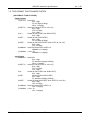
Table of Contents
1.
FEATURE SUMMARY ...................................................................................................................... 1
1.1. BAND COVERAGE.................................................................................................................... 1
1.2. NO PROGRAMMING REQUIRED............................................................................................. 2
1.3. SIMPLE USER INTERFACE...................................................................................................... 2
1.4. SERVICE TYPE......................................................................................................................... 2
1.5. AUDIO RECORDING................................................................................................................. 2
1.6. MEMORY................................................................................................................................... 2
1.7. CHANNEL MEMORY SCAN ...................................................................................................... 2
1.8. PRIORITY SCAN ....................................................................................................................... 2
1.9. SEARCH WITH SCAN............................................................................................................... 2
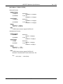
1.10. SCAN SPEED............................................................................................................................ 3
1.11. AVOID FUNCTION FOR SCANNING ........................................................................................ 3
1.12. TEMPORARY AVOID................................................................................................................. 3
1.13. QUICK KEY ............................................................................................................................... 3
1.14. STARTUP CONFIGURATION.................................................................................................... 3
1.15. CHANNEL ALERT...................................................................................................................... 3
1.16. DATA NAMING........................................................................................................................... 3
1.17. DUPLICATE INPUT ALERT ....................................................................................................... 3
1.18. NUMBER TAG ........................................................................................................................... 3
1.19. TRUNK TRACKING ................................................................................................................... 3
1.20. APCO PROJECT25 DECODER ................................................................................................ 3
1.21. P25 AUTO ADJUST THRESHOLD ............................................................................................ 3
1.22. MULTI SITE SYSTEM................................................................................................................ 4
1.23. CONTROL CHANNEL ONLY ..................................................................................................... 4
1.24. P25 ONE - FREQ TRUNK ......................................................................................................... 4
1.25. PRIORITY ID SCAN .................................................................................................................. 4
1.26. CUSTOM SEARCH ................................................................................................................... 4
1.27. QUICK SEARCH........................................................................................................................ 4
1.28. SEARCH SPEED / TURBO SEARCH ....................................................................................... 4
1.29. AVOID FUNCTION FOR SEARCHING...................................................................................... 4
1.30. SEARCH KEY............................................................................................................................ 4
1.31. BROADCAST SCREEN............................................................................................................. 4
1.32. ATTENUATOR ........................................................................................................................... 4
1.33. CODE SEARCH......................................................................................................................... 5
1.34. P25 NAC .................................................................................................................................... 5
1.35. VOLUME OFFSET..................................................................................................................... 5
1.36. IF EXCHANGE........................................................................................................................... 5
1.37. DROPOUT DELAY..................................................................................................................... 5
1.38. WEATHER AND SAME ALERT ................................................................................................. 5
1.39. CLOSE CALL............................................................................................................................. 5
1.40. CLOSE CALL TEMPORARY STORE ........................................................................................ 5
1.41. TONE-OUT-SEQUENTIAL DECODE ........................................................................................ 5
1.42. LOCATION BASED SCANNING................................................................................................ 5
1.43. PC CONTROL ........................................................................................................................... 5
For Internal Use Only
i
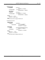
1.44.
1.45.
1.46.
1.47.
1.48.
1.49.
1.50.
1.51.
1.52.
1.53.
1.54.
1.55.
1.56.
1.57.
1.58.
1.59.
1.60.
< UB375Z Operation Specification >
Ver. 1.09
LCD AND KEYPAD BACKLIGHT............................................................................................... 5
TONE VOLUME ADJUST .......................................................................................................... 6
EDIT FAVORITE LIST................................................................................................................ 6
ORANGE WIRE ......................................................................................................................... 6
AUDIO AGC ............................................................................................................................... 6
REPEATER REVERSE.............................................................................................................. 6
MEMORY BACK UP .................................................................................................................. 6
EDACS SYSTEM KEY............................................................................................................... 6
TRUNKING DISCOVERY .......................................................................................................... 6
CONVENTIONAL DISCOVERY................................................................................................. 6
TRUNKED SYSTEM ANALYZER (T.B.D.) ................................................................................. 6
EDACS / LTR LCN FINDER (T.B.D.) ......................................................................................... 6
RF POWER PLOT (T.B.D.) ........................................................................................................ 6
RAW DATA OUTPUT (T.B.D.) .................................................................................................... 7
AUDIO FEEDING (T.B.D.) ......................................................................................................... 7
REMOTE CONTROL (T.B.D.) .................................................................................................... 7
Wi-Fi CONNECTION ................................................................................................................. 7
2.
DESIGN ............................................................................................................................................ 8
3.
CONTROLS AND KEYS................................................................................................................... 9
3.1. SCROLL CONTROL FUNCTION ............................................................................................... 9
3.2. KEY FUNCTION ........................................................................................................................ 9
4.
DISPLAYS....................................................................................................................................... 10
4.1. LCD DESIGN ........................................................................................................................... 10
4.2. ICONS ..................................................................................................................................... 10
4.3. DOT MATRIX ........................................................................................................................... 12
4.4. LCD FLASHING TIME ............................................................................................................. 12
5.
TONES............................................................................................................................................ 13
5.1. GENERAL TONES................................................................................................................... 13
5.2. WEATHER ALERT SIRENS..................................................................................................... 13
5.3. TONE IN MENU MODE ........................................................................................................... 13
5.3.1. Selecting a menu item ...................................................................................................... 13
5.3.2. Editing a name or a frequency etc .................................................................................... 13
5.4. ALERT IN SCANNER MODE................................................................................................... 14
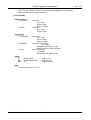
6.
OPERATIONS................................................................................................................................. 15
6.1. POWER ON ............................................................................................................................. 15
6.2. WELCOME SCREEN .............................................................................................................. 15
6.3. VOLUME AND SQUELCH CONTROL..................................................................................... 15
6.3.1. Volume Control ................................................................................................................. 15
6.3.2. Squelch Control ................................................................................................................ 15
6.3.3. P25 Condition Mode ......................................................................................................... 16
6.4. MENU MODE........................................................................................................................... 17
6.4.1. General Operations........................................................................................................... 17
6.4.1.1.
Key Operation............................................................................................................ 17
6.4.1.2.
Display Format in Menu Mode ................................................................................... 17
6.5. ADVANCED CHANNEL MENU................................................................................................ 17
6.6. SCAN MODE ........................................................................................................................... 19
6.6.1. Display while Scan Mode .................................................................................................. 19
6.6.2. Startup Key Operation....................................................................................................... 20
For Internal Use Only
ii
< UB375Z Operation Specification >
Ver. 1.09
6.6.3. Start Scanning................................................................................................................... 20
6.6.4. Scanning Order................................................................................................................. 21
6.6.5. Scanning Operation .......................................................................................................... 21
6.6.5.1.
Quick Key Operation.................................................................................................. 21
6.6.5.2.
Scan for Trunked Systems......................................................................................... 22
6.6.5.2.1.
ID Display Format ............................................................................................... 23
6.6.6. Location Based Scan ........................................................................................................ 24
6.6.7. Temporary System Hold.................................................................................................... 24
6.6.8. Temporary Department Hold ............................................................................................. 25
6.6.9. System Hold...................................................................................................................... 25
6.6.10. Department Hold ............................................................................................................... 25
6.6.11. Quick System Select......................................................................................................... 25
6.6.12. Unit ID of TGID ................................................................................................................. 25
6.6.13. Key Operation During Scan Mode .................................................................................... 26
6.7. SCAN HOLD MODE ................................................................................................................ 26
6.7.1. Display while Scan Hold Mode.......................................................................................... 26
6.7.2. General Operation ............................................................................................................ 26
6.7.3. Site Hold on Trunked System............................................................................................ 27
6.7.4. Hold on Conventional System........................................................................................... 28
6.7.5. Hold on Trunked System................................................................................................... 28
6.7.6. Hold on TalkGroup ID from ID Search / ID Scan ............................................................... 28
6.7.7. Change Site Avoid Condition ............................................................................................ 28
6.7.8. Direct Entry ....................................................................................................................... 28
6.7.8.1.
Store Frequency ........................................................................................................ 29
6.7.8.2.
Store TGID................................................................................................................. 29
6.7.8.3.
Direct Access ............................................................................................................. 30
6.7.9. Key Operation During Scan Hold Mode ............................................................................ 30
6.8. PRIORITY SCAN ..................................................................................................................... 31
6.8.1. Priority Scan...................................................................................................................... 31
6.8.2. Key Operation During Priority Scan .................................................................................. 31
6.9. PRIORITY ID SCAN ................................................................................................................ 32
6.9.1. Priority ID Scan ................................................................................................................. 32
6.9.2. Key Operation During Priority ID Scan.............................................................................. 32
6.10. SEARCH MODE ...................................................................................................................... 33
6.10.1. Display while Search Mode............................................................................................... 33
6.10.2. General Operation ............................................................................................................ 33
6.10.3. Custom Search ................................................................................................................. 33
6.10.4. Quick Search .................................................................................................................... 34
6.10.4.1. Quick Search for frequency ....................................................................................... 34
6.10.5. Key Operation During Search Mode ................................................................................. 35
6.11. SEARCH HOLD MODE ........................................................................................................... 35
6.11.1. General Operation ............................................................................................................ 35
6.11.2. Go to Quick Search Hold Directly ..................................................................................... 35
6.11.3. Direct Entry ....................................................................................................................... 35
6.11.4. Key Operation During Search Hold Mode ......................................................................... 35
6.12. CLOSE CALL MODE ............................................................................................................... 36
6.12.1. Display while Close Call Mode.......................................................................................... 36
6.12.2. Close Call Search ............................................................................................................. 36
6.12.3. Close Call Only ................................................................................................................. 37
6.12.4. Close Call Hold ................................................................................................................. 38
6.12.5. CC Bands.......................................................................................................................... 39
6.12.6. Key Operation During Close Call Only Mode .................................................................... 39
6.13. WEATHER SCAN MODE......................................................................................................... 40
6.13.1. Normal Weather Scan....................................................................................................... 40
6.13.2. Weather Alert Scan ........................................................................................................... 40
6.13.3. Weather (Alert) Scan Hold ................................................................................................ 41
6.13.4. Weather Alert Priority (WX Alt Priority) .............................................................................. 42
For Internal Use Only
iii
< UB375Z Operation Specification >
Ver. 1.09
6.13.5. Key Operation During Weather (Alert) Scan Mode ........................................................... 42
6.14. TONE-OUT MODE................................................................................................................... 42
6.14.1. Display while Tone-Out Mode ........................................................................................... 42
6.14.2. Tone-Out Standby Mode ................................................................................................... 43
6.14.3. Tone-Out Search Mode ..................................................................................................... 43
6.14.4. Tone-Out Hold Mode ......................................................................................................... 44
6.14.5. Key Operation During Tone-Out Mode .............................................................................. 45
6.14.6. Update Location Information ............................................................................................. 45
6.15. DISCOVERY FEATURE .......................................................................................................... 45
6.15.1. Trunking Discovery Mode ................................................................................................. 45
6.15.2. Conventional Discovery Mode .......................................................................................... 46
6.15.3. Review Discovery Mode.................................................................................................... 47
6.15.3.1. Review Discovery ...................................................................................................... 48
6.15.3.2. Review Run Results................................................................................................... 48
6.16. Wi-Fi CONNECTION ............................................................................................................... 49
6.16.1. Access Point Mode ........................................................................................................... 49
6.16.2. Infrastructure Mode........................................................................................................... 49
6.17. AUDIO RECORD / REPLAY .................................................................................................... 50
6.18. REPEATER FIND .................................................................................................................... 50
6.19. MEMORY INITIALIZATION...................................................................................................... 51
6.20. COMMENT ABOUT OPERATION............................................................................................ 51
7.
OTHERS ......................................................................................................................................... 52
7.1. INITIAL SETTINGS .................................................................................................................. 52
7.2. TGID FORMAT FOR TRUNKED SYSTEM .............................................................................. 53
7.3. FLEET MAP ............................................................................................................................. 59
7.4. WEATHER CHANNELS........................................................................................................... 60
7.5. CTCSS FREQUENCY ............................................................................................................. 60
7.6. DCS CODE .............................................................................................................................. 60
7.7. AVAILABLE CHARACTER....................................................................................................... 60
7.8. REVERSE LIST ....................................................................................................................... 62
7.9. REPEATER FREQUENCY LIST.............................................................................................. 62
7.10. CEA2009-SAME EVENT CODE(ANSI/CEA-2009-A October 2005)........................................ 63
7.11. FONT DATA ............................................................................................................................. 64
8.
REVISION ....................................................................................................................................... 65
For Internal Use Only
iv
< UB375Z Operation Specification >
Ver. 1.09
1. FEATURE SUMMARY
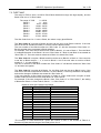
1.1. BAND COVERAGE
Table 1-1 BAND COVERAGE
Frequency (MHz)
Modulation Step (kHz)
Remark
Lower Edge Upper Edge
25.0000
26.9600
AM
5.0
Petroleum Products & Broadcast Pickup
26.9650
27.4050
AM
5.0
CB Class D Channel
27.4100
27.9950
AM
5.0
Business & Forest Products
28.0000
29.6800
NFM
20.0
10 Meter Amateur Band
29.7000
49.9900
NFM
10.0
VHF Low Band
50.0000
53.9800
NFM
20.0
6 Meter Amateur Band
54.0000
71.9500
WFM
50.0
VHF TV Broadcast 2 – 4
72.0000
75.9950
FM
5.0
Intersystem & Astronomy
76.0000
87.9500
WFM
50.0
VHF TV Broadcast 5 – 6
88.0000
107.9000
FMB
100.0
FM Broadcast
108.0000
136.9916
AM
8.33
Aircraft Band
137.0000
143.9875
NFM
12.5
Military Land Mobile
144.0000
147.9950
NFM
5.0
2 Meter Amateur Band
148.0000
150.7875
NFM
12.5
Military Land Mobile
150.8000
161.9950
NFM
5.0
VHF High Band
162.0000
173.9875
NFM
12.5
Federal Government
174.0000
215.9500
WFM
50.0
TV Broadcast 7 – 13
216.0000
224.9800
NFM
20.0
1.25 Meter Amateur Band
225.0000
379.9750
AM
25.0
UHF Aircraft Band
380.0000
399.9875
NFM
12.5
Military Band
400.0000
405.9875
NFM
12.5
Miscellaneous
406.0000
419.9875
NFM
12.5
Federal Government Land Mobile
420.0000
449.9875
NFM
12.5
70 cm Amateur Band
450.0000
469.9875
NFM
12.5
UHF Standard Band
470.0000
512.0000
NFM
12.5
UHF TV
758.0000
787.9937
NFM
6.25
Public Service Band
788.0000
805.9937
NFM
6.25
Public Service Band
806.0000
823.9875
NFM
12.5
Public Service Band
849.0125
868.9875
NFM
12.5
Public Service Band
894.0125
960.0000
NFM
12.5
Public Service Band
1240.0000
1300.0000
NFM
25.0
25 cm Amateur Band
These Frequency Ranges suit to initial step setting. Step setting will change them.
These Modulations are initial settings. They can be selected from AM / FM / NFM / WFM / FMB /
AUTO. “FMB” means FM Broadcast demodulation [WFM (Broadcast)].
These Steps are initial settings.
Steps can be selected from 5 / 6.25 / 7.5 / 8.33 / 10 / 12.5 / 15 / 20 / 25 / 50 / 100 / AUTO (kHz).
If "AUTO" is selected for Modulation or Step, the scanner works with the modulation or step of
“Band Defaults” setting.
If the Step is set to 15 kHz, inputable frequencies are xxx.x000, xxx.x150, xxx.x300, xxx.x450,
xxx.x600, xxx.x750, and xxx.x900. For example, the next frequency of 400.0900 MHz is
400.1000 MHz.
If the Step is set to 8.33kHz, inputable frequencies are xxx.x000, xxx.x083, xxx.x166, xxx.x250,
xxx.x333, xxx.x416, xxx.x500, xxx.x583, xxx.x666, xxx.x750, xxx.x833, and xxx.916.
For example, the next frequency of 100.0916 MHz is 100.1000 MHz.
For 7.5 kHz Step, frequencies between 150.8150 and 154.6250 MHz is multiple of 7.5 kHz on
the basis of 150.8150 MHz. For example, the next frequency of 150.8100 MHz is 150.8150 MHz,
and the next frequency of 154.6250 MHz is 154.6275 MHz.
For Internal Use Only
1
< UB375Z Operation Specification >
Ver. 1.09
1.2. NO PROGRAMMING REQUIRED
Factory programmed to microSD card for all known radio systems in the US and Canada.
The database is updatable through a subscription service with RadioReference.com.
1.3. SIMPLE USER INTERFACE
Zip Code Selection Scan
Zip code entry for instant reception of local Police, Fire and EMS (ambulance).
Auto Locate
“Auto Locate” mode determines local systems to scan with no user input.
Location Base Scan
Connect a GPS for precise system selection and continuing reselection when you travel.
Favorite Scan
Select which favorites list the BCD536HP uses for reception. BCD536HP will only use channels
from the chosen Favorites list. The BCD536HP can scan multi-favorites lists and full database at
once.
1.4. SERVICE TYPE
BCD536HP scans channels using the selected service(s)
Total 39 types:
Multi-Dispatch, Law Dispatch, Fire Dispatch, EMS Dispatch, Multi-Tac,
Law Tac, Fire-Tac, EMS-Tac, Interop, Hospital,
Ham, Public Works, Aircraft, Federal, Business,
Railroad, Multi-Talk, Other, Law Talk, Fire-Talk, EMS-Talk,
Transportation, Emergency Ops, Military, Media, Schools,
Security, Utilities, Corrections,
Racing Officials, Racing Teams,
Custom 1 - Custom 8
1.5. AUDIO RECORDING
BCD536HP can record transmissions. You can replay recorded audio data.
1.6. MEMORY
External : 4GB SD card
Internal : Dynamic allocation. (Total 300,000 memory blocks)
1.7. CHANNEL MEMORY SCAN
The user can scan Channels already programmed.
The scanner can track both conventional and trunked System at the same time.
1.8. PRIORITY SCAN
The scanner checks conventional Priority Channels periodically while scanning. DND(Do-Not
Disturb) mode keeps the scanner from interrupting transmissions during receiving.
1.9. SEARCH WITH SCAN
The scanner can do Custom Search with Scan sequentially.
For Internal Use Only
2
< UB375Z Operation Specification >
Ver. 1.09
1.10. SCAN SPEED
100 CH/SEC. in Scan Mode (max)
1.11. AVOID FUNCTION FOR SCANNING
The user can avoid any System, Department and Channel.
Avoided Channel will be skipped during scanning.
If the System or Department is avoided, the Channels belonging to that will be skipped during
scanning.
1.12. TEMPORARY AVOID
Temporary AVOID is cleared by power-off.
1.13. QUICK KEY
The user can set Quick keys on favorites lists and systems.
Favorites list Quick Key : “0” to “99”.
System Quick Key : “0” to “99”.
The user can turn on or Off Quick Key by the keypad. (Detail: 6.6.5.1. Quick Key Operation)
1.14. STARTUP CONFIGURATION
This function modifies Favorites Lists Monitor Status according to the setting of Startup Key.
1.15. CHANNEL ALERT
The user can set alert tone and alert light for each Channel.
This function alerts the user when the Channel becomes active.
1.16. DATA NAMING
The user can name to each System, Department, Channel, TGID, Custom Search Range, SAME
Group and Tone-Out. The scanner allows up to 64 characters for each name.
1.17. DUPLICATE INPUT ALERT
The scanner will inform the user that now inputted Name, frequency and so on had already
stored in Memory or in same System.
1.18. NUMBER TAG
This function is registered to Favorites Lists, System and Channel.
The user can access a system or a channel directly by using Number Tag.
1.19. TRUNK TRACKING
The scanner tracks following Systems.
• Motorola Type I 800
• Motorola Type II 800, 900, UHF, VHF
• EDACS WIDE, NARROW, With EDACS System Key
• LTR
• APCO P25 Standard, Phase2, P25 One-Freq
1.20. APCO PROJECT25 DECODER
Allows the user to hear the digitalized voice data that is compliant with the APCO Project25
standard. BCD536HP supports PHASE2 TDMA systems.
1.21. P25 AUTO ADJUST THRESHOLD
The scanner adjusts the threshold level automatically.
For Internal Use Only
3
< UB375Z Operation Specification >
Ver. 1.09
1.22. MULTI SITE SYSTEM
All trunked systems are able to have more than one site. The Multi Site System uses the
common TGIDs.
1.23. CONTROL CHANNEL ONLY
Trunking is performed using Control Channel data only. The user does not have to program
Voice channel frequencies in to memory (For Motorola System and APCO P25 Standard).
1.24. P25 ONE - FREQ TRUNK
This system is a kind of conventional P25 system using NAC and TGID for squelch control.
ID Search and ID Scan are available like other trunked systems.
1.25. PRIORITY ID SCAN
This function is very similar to conventional priority although there is no "interrupt" during the
transmissions.
Priorities are checked in between transmissions.
This works on the Motorola and EDACS (Wide, Narrow), LTR, APCO P25 Standard.
1.26. CUSTOM SEARCH
The user can program Custom Search Ranges up to 10, and the user can search these Ranges
sequentially.
1.27. QUICK SEARCH
If the user stops on a Channel in a conventional System, the user can start searching from the
current frequency.
If the user stops on a Channel in a trunked System, the user can begin trunk ID searching in the
System.
1.28. SEARCH SPEED / TURBO SEARCH
100 STEP/SEC. in Search Mode (max)
300 STEP/SEC. in Search Mode (max) - (Turbo Search)
- except for 5 kHz step.
- for 5 kHz step
*Turbo Search feature is built in and works at 5 kHz step setting automatically.
1.29. AVOID FUNCTION FOR SEARCHING
The user can avoid any frequency up to 500.
The limit of temporary AVOID frequencies: 250
The limit of permanent AVOID frequencies: 250
Avoided frequencies will be skipped in Search Mode or Close Call Mode.
And the user can review all avoided frequencies in Menu Mode.
1.30. SEARCH KEY
Search key is short cut to start searching for a single search range.
There are search keys from 1 to 3.
1.31. BROADCAST SCREEN
Allows the scanner to ignore hits on Pager, FM, UHF TV, VHF TV, NOAA WX and band*
frequencies.
* The band is a frequency band that the user set respectively.
1.32. ATTENUATOR
The user can attenuate the incoming signal for channels that get interference from strong signal
sources.
For Internal Use Only
4
< UB375Z Operation Specification >
The user can set a global attenuator to apply attenuation to all reception.
Ver. 1.09
1.33. CODE SEARCH
Rapid search for the CTCSS/DCS used during a transmission.
1.34. P25 NAC
P25 Network Access Code (NAC) is used to provide selective squelch operation on channels.
The scanner will detect the NAC that is being used on a P25 digital channel.
NAC will be shown in Hexadecimal Format.
1.35. VOLUME OFFSET
Adjust a volume level from -3 to +3 step to balance audio level of each channel.
This function is registered in each channel.
1.36. IF EXCHANGE
Switches the current frequency to use a different IF(intermediate frequency) for receiving radio
signals to avoid interference.
1.37. DROPOUT DELAY
Controls whether the scanner pauses at the end of a transmission to wait for a reply.
User can set Delay time by Each Channels. The user can also set the Delay time for Search,
Close Call and Tone-Out.
The user can set the minus delay time. That case, the scanner only stops on transmissions for a
set time, then automatically resumes.
1.38. WEATHER AND SAME ALERT
The scanner can alert to Weather Alert Tone, all FIPS or selected FIPS.
1.39. CLOSE CALL
The scanner can immediately detect and lock onto a transmission above threshold signal
strength. DND (Don't Disturb) mode checks for Close Call activity in between channel reception
so active channels are not interrupted.
1.40. CLOSE CALL TEMPORARY STORE
The scanner scans the last 10 frequencies captured by Close Call so that you can continue to
receive the signal even after the signal is not strong enough to trigger a Close Call hit.
User can confirm these received frequencies (last 10 frequencies) by Search with Scan feature.
1.41. TONE-OUT-SEQUENTIAL DECODE
Lets you set the scanner to act as a two-tone pager for fire tone-out standby. If you do not know
the tones being used, the scanner can detect the tones when it receives a page.
1.42. LOCATION BASED SCANNING
The scanner can automatically unavoid and avoid systems, sites and channel groups based on
your current location as provided by an external GPS unit (not included).
1.43. PC CONTROL
The user can download information into the scanner and control the scanner via your personal
computer.
1.44. LCD AND KEYPAD BACKLIGHT
The user can select LCD backlight condition.
For Internal Use Only
5
< UB375Z Operation Specification >
Ver. 1.09
It has 3 dimmer steps.
The Keypad backlight is single white.
The user can turn on/off the LCD and the Keypad backlight.
And the scanner will turn on/off the LCD and the Keypad backlight automatically according to
backlight setting.
1.45. TONE VOLUME ADJUST
This feature allows the user to adjust a volume level of the following tones:
Key Beep, Emergency Alert, Channel Alert, Close Call Alert, Tone-Out detection Alert.
1.46. EDIT FAVORITE LIST
You can create new systems in the unit.
1.47. ORANGE WIRE
Orange wire is dimmer input terminal of Backlight.
The scanner adjusts Backlight brightness when the driver turns on or off the Headlight.
1.48. AUDIO AGC
The scanner judges strength of the signal and changes the volume automatically.
In this item, the user can set Analog Audio and Digital Audio.
1.49. REPEATER REVERSE
One-touch key lets user switch to hearing the input frequency on a conventional repeater system
or trunked system.
1.50. MEMORY BACK UP
Scanner memory is backed up semi permanently.
And the user can initialize the Memory.
1.51. EDACS SYSTEM KEY
EDACS System Key is used to modify the command word on control channel.
receives automatically the EDACS system with EDACS System Key.
Scanner
1.52. TRUNKING DISCOVERY
Monitors the selected trunked system, looking only for "new" channels. When a new channel is
active, the audio is recorded. A log is kept of all hits and can be reviewed, later.
1.53. CONVENTIONAL DISCOVERY
Similar to trunking discovery mode, but searches a frequency range and compares to
frequencies used in the set location/range to determine whether a hit is "new" or not.
1.54. TRUNKED SYSTEM ANALYZER (T.B.D.)
Trunked System Analyzer includes System Load / Reception Status, Current Activity, LCN
Monitor, Activity Log and Talk Group Converter.
1.55. EDACS / LTR LCN FINDER (T.B.D.)
Monitors system traffic on the programmed frequencies and correlates frequency activity against
the LCNs of the active channels. Once full correlation is made, allows you to save the LCN
assignments back to the system in question.
1.56. RF POWER PLOT (T.B.D.)
Plots RF level vs. time for a single frequency.
For Internal Use Only
6
< UB375Z Operation Specification >
1.57. RAW DATA OUTPUT (T.B.D.)
BCD536HP outputs received signal raw data stream to USB port.
1.58. AUDIO FEEDING (T.B.D.)
User can get current audio recording files promptly by USB connection.
1.59. REMOTE CONTROL (T.B.D.)
User can control BCD536HP from PC by USB connection and Wi-Fi connection.
1.60. Wi-Fi CONNECTION
The scanner connect to external Wi-Fi equipments through the Wi-Fi module.
For Internal Use Only
7
Ver. 1.09
< UB375Z Operation Specification >
Ver. 1.09
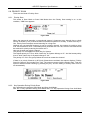
2. DESIGN
This design has some difference from the actual design and is intended for reference only.
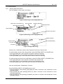
Figure 2-1 Front Panel
For Internal Use Only
8
< UB375Z Operation Specification >
Ver. 1.09
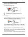
3. CONTROLS AND KEYS
There are Normal Mode and Function Mode in key operation.
Normal Mode:
Normal Mode means that is not Function Mode. In this mode, F icon is not displayed.
Function Mode:
Pressing [Rotary / FUNC] knob puts the scanner into Function Mode for 3 seconds. While it is in
Function Mode, the scanner displays F icon.
Figure 3-1
And pressing [Rotary / FUNC] knob again in each Function Mode to return to Normal Mode and
F icon disappears.
“Long press” means pressing a key more than 2 seconds.
3.1. SCROLL CONTROL FUNCTION
POW(Power) / VOL(Volume) Knob (Backlight key)
• Turn this knob to turn on or off the scanner.
• Turn this knob to adjust the volume level.
• Press this knob to illuminate the LCD backlight.
(Off → Low → Middle → High)
SQ(Squelch) Knob (Close Call key)
• Turn this knob to adjust the squelch level.
• Press this knob to toggle Close Call Mode. (CC DND / CC Priority / Off)
• Long press this knob to go to Close Call Only Mode.
Function + SQ(Squelch) Knob
• Press this knob to go to Tone-Out Standby Mode.
Rotary Knob (FUNC key)
• Turn this knob to select Channel, Frequency or TGID in Hold Mode.
• Turn this knob to select Menu item in Menu Mode.
• Turn this knob to select a character while editing name.
• Turn this knob to resume scanning or searching while monitoring.
• Press this knob to go to Function Mode.
• If the user presses any key in Function Mode that cause a mode change, the scanner will
cancel the Function Mode, and return to the Normal Mode.
• Press this knob to decide the input data or a Menu Item in Menu Mode.
3.2. KEY FUNCTION
Refer to APPENDIX “Key Action List”. (UB375Z_KeyActionList_V0_15.pdf)
For Internal Use Only
9
< UB375Z Operation Specification >
Ver. 1.09
4. DISPLAYS
4.1. LCD DESIGN
The design is different from the actual design and is intended for reference only.
Figure 4-1 Example 1
Figure 4-2 Example 2
Figure 4-3 Example 3
4.2. ICONS
Fx: :
This icon appears with icons of Quick Key number for Favorites (from “0” to “99”).
“x” shows current ten’s place of Quick Key for Favorite.
Sx: :
This icon appears with icons of Quick Key number for Systems and Sites (from “0” to “99”).
“x” shows current ten’s place of Quick Key for System or Site.
0 - 9:
In SCAN mode, the numbers of assigned off Quick Key for Favorites List and avoided Quick Key
for Systems are displayed. And a current scanning number blinks.
In SCAN HOLD mode, the Quick Key number of the current Favorite/System is displayed.
The numbers of selected User Ranges appear while Custom Search. And the number of
searching Range blinks.
HOLD:
This icon appears in one of Hold Modes.
AVOID :
This icon appears at Permanent avoided System/Department/Channel. At this time, AVOID
information is memorized to SD card. So, if user power on again, then that
System/Department/Channel is avoided.
For Internal Use Only
10
< UB375Z Operation Specification >
Ver. 1.09
AVOID:
This icon appears at Temporary avoided System/Department/Channel . At this time, AVOID
information is not memorized to SD card. So, if user power on again, then that
System/Department/Channel is not avoided.
PRI:
This icon turns on while the Priority Scan works.
PRI:
This icon turns on while the Priority DND Scan works.
GPS:
This icon appears when the scanner receives GPS data.
AM / FM / NFM / FMB / WFM:
These icons show the modulation type. "AM", "FM" ,"NFM", "FMB" or "WFM" will appear.
ATT:
This icon appears when a channel has attenuator on and this blinks while global attenuator is on.
P25:
This icon shows the receiving digitalized voice of APCO P25.
LNK:
This icon appears when data is received on VOICE CHANNEL.
Then, this shows in the same place as "P25" icon.
DAT:
This icon appears when data on CONTROL CHANNEL is received.
Then, this shows in the same place as "P25" icon.
ENC:
This icon appears when the digitalized voice from which APCO P25 is encrypted is received and
the scanner mutes audio.
Then, this shows in the same place as "P25" icon.
C162.2 / DCS023 / NAC:000 / etc.:
The scanner displays the data of CTCSS/DCS/P25 NAC in the location here. Then, this shows in
the same place as "P25" icon.
SCR:
This icon appears when one or more Broadcast Screen Band is set to on.
WX:
This icon turns on while the Weather Alert Priority Scan works.
F (Function icon) :
This icon appears while Function Mode.
P (Priority Channel) :
This icon appears when the channel set to “Priority On".
(Signal Indicator) :
This icon shows strength of the signal from 0 to 5.
(Close Call Priority ) :
This icon appears when the Close Call Mode is CC Priority Mode.
This blinks while Close Call Only Mode or when the scanner detects the Close Call.
For Internal Use Only
11
< UB375Z Operation Specification >
(Close Call DND) :
This icon appears when the Close Call Mode is CC DND Mode.
This is a reverse display of Close Call Priority icon.
(Wi-Fi) :
This icon appears when Wi-Fi module is not connect.
4.3. DOT MATRIX
288 x 64 Full Dot Matrix
4.4. LCD FLASHING TIME
About 500 ms ON / About 500 ms OFF (nearly 1.0 Hz)
For Internal Use Only
12
Ver. 1.09
< UB375Z Operation Specification >
Ver. 1.09
5. TONES
The scanner will be able to produce 3 fundamental tones, high (1200 Hz), middle (920 Hz), and
low (640 Hz) tones. Furthermore, there are Alert Tone and Weather Alert Sirens with which other
sound sounds.
Additionally, special alert tones (CC alert, Emergency alert and WX alert, etc) can be set to
custom volume levels.
5.1. GENERAL TONES
Key Touch Tone
When the user presses valid keys, the scanner will sound single high beep for 50 ms.
Confirmation Tone
The scanner will sound double high beep for confirmation (50 ms beep - 100 ms silent - 50 ms
beep).
Exec Tone
When the user presses [E yes] key etc. to accept the entry or setting, the scanner will sound
high-middle beep (75 ms high beep - 25 ms silent - 75 ms middle beep).
Error Tone
When the user presses a key that does not have a valid function in the current mode, the
scanner will sound a triple low beep (75 ms beep - 25 ms silent -- repeat 2 times)
5.2. WEATHER ALERT SIRENS
The scanner sounds following tones.
For Warning
[100 ms 120 Hz - (20 ms every 150 - 195 Hz in 5 Hz step) - (30 ms every 200 - 590 Hz in 10 Hz
step) - 500 ms 600 Hz - 100 ms silent] --- repeat
For Watch
[(50 ms 800 Hz - 30 ms silent - 50 ms 1050 Hz - 30 ms silent) -- repeat 3 times - 170 ms silent] -- repeat
For Advisory
[100 ms 800 Hz - 50 ms silent - 100 ms 1050 Hz - 500 ms silent] -– repeat
For Weather Alert Tone: Same as Weather Alert Siren For Warning.
5.3. TONE IN MENU MODE
5.3.1. Selecting a menu item
As the user steps to the next menu item by turning [Rotary / FUNC] knob, the scanner will sound
a single high beep for 100 ms.
However, if the menu item is the last item and the user turns [Rotary / FUNC] knob in the
clockwise direction, the scanner will sound a double high beep (75 ms beep - 25 ms silent - 75
ms beep).
When the user selects a menu item by pressing [E yes] key, the scanner will sound a single
middle beep for 100 ms.
Or, as the user returns to a previous menu by pressing [MENU] key, the scanner will sound a
double middle beep (75 ms beep - 25 ms silent - 75 ms beep).
5.3.2. Editing a name or a frequency etc
When the user selects the letters, the scanner sounds a single high beep as often as the user
turns [Rotary / FUNC] knob.
When the user moves cursor from the left to the right, the scanner will sound a single middle
beep (100 ms). Or, when the user moves cursor from the right to the left, the scanner will sound
a double middle beep (75 ms beep - 25 ms silent - 75 ms beep).
For Internal Use Only
13
< UB375Z Operation Specification >
Ver. 1.09
If the user stores the inputted data by pressing [E yes] key, the scanner sounds Exec Tone.
5.4. ALERT IN SCANNER MODE
The user can select channel or frequency alert from Alert1-9 in Menu by "Set Alert" and
"Emergency Alert".
The alert that can select in menu is as follows.
Alert 1
[50 ms 3000 Hz - 20 ms silent - 50 ms 3000 Hz - 20 ms silent - 50 ms 3000 Hz]
Alert 2
[(50 ms 800 Hz - 20 ms silent - 50 ms 1050 Hz - 20 ms silent) -- repeat 2 times]
Alert 3
[50 ms 800 Hz - 20 ms silent - 50 ms 1050 Hz - 20 ms silent - 100 ms 3000 Hz]
Alert 4
[(10 ms 120 Hz - 10 ms 800 Hz - 10 ms 1200 Hz) -- repeat 5 times]
Alert 5
[150 ms 1200 Hz]
Alert 6
[70 ms 1200 Hz - 50 ms silent - 70 ms 1200 Hz]
Alert 7
[(200 ms 2000 Hz - 10 ms silent - 150 ms 800 Hz) -- repeat 3 times]
Alert 8
[40 ms 500 Hz - 10 ms silent - 40 ms 500 Hz - 10 ms silent - 40 ms 500 Hz]
Alert 9
[(70 ms 2400 Hz - 20 ms silent - 70 ms 3000 Hz - 70 ms silent) -- repeat 2 times]
For Internal Use Only
14
< UB375Z Operation Specification >
Ver. 1.09
6. OPERATIONS
NOTE: Pressing [AVOID] key cancels the prompt and exit from Menu and so on immediately.
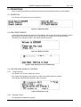
6.1. POWER ON
Turn [POW / VOL] knob to turn on the scanner.
Figure 6-1 Opening Screen
6.2. WELCOME SCREEN
If the scanner detects that the real-time clock setting is lost or stop, the scanner displays a popup
warning when the scanner powers up, then go directly to the date and clock setting screen.
According to an indication screen, user inputs the date and time.
Figure 6-2 Welcome Screen
Figure 6-3 No Scanning List (3 Line Mode On)
6.3. VOLUME AND SQUELCH CONTROL
6.3.1. Volume Control
Turn [POW / VOL] knob to adjust the volume.
The volume level appears in the screen top right corner while adjust the volume.
This indicator automatically disappears after 3 seconds.
Figure 6-4 SQL/VOL Level
6.3.2. Squelch Control
Turn [SQ] knob to adjust the squelch.
For Internal Use Only
15
< UB375Z Operation Specification >
Ver. 1.09
The squelch level appears in the screen top right corner while adjust the squelch.
This indicator automatically disappears after 3 seconds.
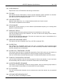
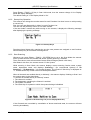
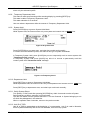
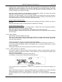
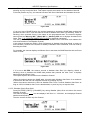
6.3.3. P25 Condition Mode
To go to P25 Condition Mode, press [POW / VOL] knob in Function Mode.
The user can see the current status of APCO decoding and the Threshold Level in this mode.
User can change Threshold Level when MANUAL mode by rotating [Rotary / FUNC] knob.
APCO Decode Error Rate
Threshold Level
P25 Condition Mode
Thresholds Voltage
Figure 6-5 P25 Condition (AUTO)
Figure 6-6 P25 Condition (MANUAL)
Press [Rotary / FUNC] knob + [POW / VOL] knob to quit the P25 Condition Mode.
This mode doesn't have the time-out.
For Internal Use Only
16
< UB375Z Operation Specification >
Ver. 1.09
6.4. MENU MODE
Refer to APPENDIX “Menu Tree Specification”. (UB375Z_MenuTreeSpecification_V0_15.pdf)
6.4.1. General Operations
6.4.1.1. Key Operation
Enter the Menu Mode:
-> Press [MENU] key
To select a Menu item:
-> Turn [Rotary / FUNC] knob
To decide the Menu item or input data:
-> Press [E yes] key or [Rotary / FUNC] knob
To Return to the previous menu by one layer:
-> Press [MENU] key
To exit from Menu Mode:
-> Press [MENU] key at Top Menu to return to previous mode
-> Press [AVOID] key to exit Menu and return to previous mode
Note: Press [Rotary / FUNC] knob can be used instead of [E yes] key in Menu Mode or at
various prompts.
If cursor go to the bottom of the Menu, the next step will move to the top of the menu.
Menu items are described as the bold letter in this specification.
The message “Press Any Key” in Menu Mode means press any physical key except the [AVOID]
key. [AVOID] key is used to exit from Menu Mode directly.
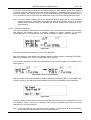
6.4.1.2. Display Format in Menu Mode
The Menu Item screen is four-line mode.
The first line displays the Menu Item Name and the selection items are displayed below.
For example, the Menu display of a channel modulation setting is as follows.
Figure 6-7
The user selects setting item by turning [Rotary / FUNC] knob and decides the item by pressing
[E yes] key.
6.5. ADVANCED CHANNEL MENU
A menu to choose the action for the current channel appears when user press [E yes] key while
the scanner receive a signal or in Scan Hold Mode. This menu is Advanced Channel Menu.
The items to display by this menu are as follows. The scanner displays only an executable item
at that time.
- Edit Current Channel
- Add to Favorites List
- Save Sub Audio
- Save Talk Group ID
- Save Unit ID
For Internal Use Only
17
< UB375Z Operation Specification >
Ver. 1.09
Edit Current Channel
This item is function that user edits the stored data of target Channel.
Add to Favorites List
This item store Channel for Scan in Favorites List. Favorites List where it is not load to CMB is
also targeted for storage.
Save Sub Audio
This item store Sub Audio which the scanner received in Scan to CMB and Favorites List.
Save Talk Group ID
This item store the Talk Group ID that the scanner received in ID Search to CMB and Favorites
List.
Save Unit ID
This item store the Unit ID that the scanner received in Unit ID Search to CMB and Favorites
List..
Refer to APPENDIX “Advanced Channel Menu”. (UB375Z_AdvancedChannelMenu_V0_02.pdf)
For Internal Use Only
18
< UB375Z Operation Specification >
Ver. 1.09
6.6. SCAN MODE
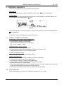
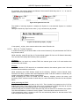
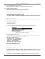
6.6.1. Display while Scan Mode
The LCD display in Scan mode is as follows.
Figure 6-8 Scanning (3 Line Display Mode On)
Quick Key for Favorites List
Time and Date
Scanning Direction
Department Name
Quick Key for System
System Name
Favorites List Name
Figure 6-9 Scanning (3 Line Display Mode Off)
Signal Strength
CTCSS/DCS/NAC
System Name
Function Tag
Frequency
Figure 6-10 Signal Receiving
Scanner has 3 Hold Mode. System Hold, Department Hold and Channel Hold.
To make hold the scanner from Normal Mode, press [SYSTEM] / [DEPT] / [CHANNEL] key.
• Press [SYSTEM] key if user would like to System Hold from Scanning
• Press [DEPT] key if user would like to Department Hold from Scanning
• Press [CHANNEL] key if user would like to Channel Hold from Scanning
To make resume the scanner from Hold Mode, press [SYSTEM] / [DEPT] / [CHANNEL] key.
• Press [SYSTEM] key if user would like to resume from System Hold
• Press [DEPT] key if user would like to resume from Department Hold
• Press [CHANNEL] key if user would like to resume from Channel Hold
User can avoid System / Department / Channel.
Press [SYSTEM] / [DEPT] / [CHANNEL] key to avoid.
• Press [AVOID] key after pressing [SYSTEM] key within 2 seconds if user would like to avoid
Indicated System
• Press [AVOID] key after pressing [DEPT] key within 2 seconds if user would like to avoid
Indicated Department
• Press [AVOID] key after pressing [CHANNEL] key within 2 seconds if user would like to avoid
Indicated Channel
For Internal Use Only
19
< UB375Z Operation Specification >
User can select the 3 Line Display Mode On/ Off.
Ver. 1.09
Press [Rotary / FUNC] + [9] key in Scan Hold mode, then the scanner change 3 Line Display
Mode with Popup Message.
The default Setting of 3 Line Display Mode is “On”.
6.6.2. Startup Key Operation
The scanner can change the monitor status for each Favorites List when it turns on with pressing
a numeric key.
First, the user sets Startup Key in Menu for each Favorites List.
The user can set plural key from 0 to 9 for each favorite.
If the user holds a number key while turning on the scanner, it displays the following message
after displaying the opening message.
Figure 6-11 Startup Key 0
Favorites whose Startup Key matches the one the user presses are assigned on and favorites
whose Startup Key do not match are assigned off.
6.6.3. Start Scanning
Whenever you press [Rotary / FUNC] + [SYSTEM] key to go to the Scan Mode the scanner
scans systems that are not avoided and whose System quick key is enabled.
Then, the scanner scans all unavoided Custom Search Ranges (Search with Scan).
After Search with Scan, the scanner scans CC Hits System.
While scanning in Scan Mode, the scanner displays current scanning favorite name, system
name, department name, and displays "Scanning..." (for conventional System) or "ID
Scanning...", "ID Searching..." (for trunked System). The turned off Quick Key is displayed as
“*”. And the Quick Key for the Current Favorite/System blinks.
When all channels are avoided directly or indirectly*, the scanner displays "Nothing to Scan" and
the scanner stays in the Scan Mode.
*"A channel is avoided directly or indirectly" means:
1. The channel is avoided.
2. The department containing the Channel is avoided.
3. The system is avoided.
4. The Quick Key for systems to which that system belongs is disabled.
Figure 6-12 No Scanning List (3 Line Display Mode On)
If the Channels are unavoided by cancellation of above-mentioned state, the scanner will start
scanning immediately.
For Internal Use Only
20
< UB375Z Operation Specification >
Ver. 1.09
6.6.4. Scanning Order
First, systems belonging to scan. Then systems that belong to Quick Key are scanned in order.
Systems to which a Quick Key isn’t set are scanned last.
The scanner searches Custom Search from range in turn.
After Custom Search ends, the scanner scans a system that is named “Close Call Hits*”
*This is a system where the scanner automatically stores the frequencies found by Close Call.
If “Close Call Hits” system has no frequencies, the scanner does not scan this system. After the
scanner finishes scanning “Close Call Hits” system, the scanner scans from top system again.
You can change the scanning direction by turning [Rotary / FUNC] knob.
The scanning order of the systems belonging to the same Quick Key is the order registered to
that Quick Key. The scanning order of the systems / sites belonging to no Quick Key is the order
set to none.
When a system is created, the scanner automatically sets the Quick Key to none. So, if you do
not change the Quick Key setting, the scanning order will be the order of system creation.
The scanning order of Channels in a conventional system’s channel group depends in the order
of Channel creation.
However, avoided or disabled items* are not scanned.
*Avoided or disabled items means assigned off Favorites List, avoided System, avoided
Department, avoided Channels, disabled Favorite/System Quick Keys.
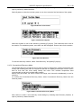
6.6.5. Scanning Operation
6.6.5.1. Quick Key Operation
In Conventional System, Quick Key is set for the system.
Enabled quick keys show their number. Disabled quick keys show “*”. Quick keys with no
system assigned show "―".
Structure of Quick Key is as follows;
ff.ss
System Quick Key Number
Favorite Quick Key Number
At First, user input Favorite Quick Key Number. Next, press [.no] key. And input System Quick
Key Number. Then press [E yes] key. So, Status of Specified System is change (“0” to “*”).
Systems belonging to turn off Quick Key are not scanned. Then the Quick Key for Favorite /
System that turn off displays “*”.
Figure 6-13 Favorite Quick Key Number
Figure 6-14 System Quick Key Number
During scanning, the user can turn On or Off a system by Quick Key with [1] - [9], [0] key.
*It cannot turn on the Quick Key that has no Favorite or System.
For Internal Use Only
21
< UB375Z Operation Specification >
Ver. 1.09
*The displayed Quick Key for system shows the turned on its current scanning system.
For example, the scanner displays as follows if the turned off Quick Keys are “3”, “4”, “6”, and “9”.
System 01 turn Off by Quick Key.
Figure 6-15 System 01 turn Off
The details of scanning depend on whether the System is a conventional System or a trunked
System.
Change to Quick Key input screen when [.no] or numeric key is pressed.
Figure 6-16 Quick Key Input [. no] key
If user press [.no] key, then scanner selects the current Favorite List.
6.6.5.2. Scan for Trunked Systems
In trunked Scanning, the scanner holds on the control channel (C-Ch) and decodes the TGID as
they become active.
While scanning, press [E yes] key in Function Mode toggles ID Scan and ID Search alternately.
The user also can change this mode by Menu operation.
ID Search :
If a TGID does not match any avoided TGID, the scanner goes to the V-Ch and monitors the
transmission until it ends.
ID Scan :
If a TGID matches a TGID stored in an unavoided channel, the scanner goes to the V-Ch and
monitors the transmission until it ends.
While monitoring the TGID already stored into the Memory, displays current channel name,
Favorites List name, System name and Department name. And the numbers of Quick Key for
current monitoring Favorites List and System blinks.
While monitoring the TGID not stored into the Memory, displays current site name, and
monitoring TGID. And the number of Quick Key for current monitoring Favorites List and System
blinks.
While monitoring the TGID:
Turn [Rotary / FUNC] knob to return to the C-Ch. Then it waits for a moment on the C-Ch for
finding other TGID. If the scanner finds other one, it monitors found TGID. But there is only the
TGID that was being monitored just before, it monitors that TGID again.
Press [AVOID] key to avoid the TGID and store this TGID to the list of ID Avoids of the system.
This avoid information is common to every System. Then the scanner returns to the C-Ch.
If the transmission ends, it returns to the C-Ch and exclusively listens for the last-active TGID
until the system delay time expires.
For Internal Use Only
22
< UB375Z Operation Specification >
Ver. 1.09
If it exceeds the system delay time, the scanner checks to see if the System Hold time has
elapsed. If so, the scanner advances to the next System. If Sysytem Hold Time has not elapsed,
the scanner continues to monitor the C-Ch for TGID activity.
Avoid Operation
The user can avoid for each Site and System.
In Trunked Systems, one system can have some sites and those sites can share the same
TalkGroup ID.
If the user avoided a TGID, it means the TGID is avoided for all site in the system.
6.6.5.2.1. ID Display Format
The scanner displays received ID as following format on second line.
Normal ID
The scanner displays as "TGID:xxxx" for no-named TGID.
(xxxx: The format of each type.)
Example)
MOT Type I ID
MOT Type II
P25 ID
EDACS
LTR
: TGID:101-1
: TGID:12345
: TGID:123h
: TGID:12345
: TGID:1234h
: TGID:01-023
: TGID:147
: TGID:0-20-254
(Decimal Format)
(Hexadecimal Format)
(Decimal Format)
(Hexadecimal Format)
(AFS Format)
(Decimal Format)
I-Call
The scanner displays ID as "TGID:xxxxxx" for no-named TGID. In order to show that ID is I-Call,
"i" is displayed on the left end of ID.
Example)
MOT Type I I-Call
MOT Type II
P25 I-Call
EDACS I-Call
: TGID:i12345
: TGID:i12345
: TGID:i1234h
: TGID:i12345678
: TGID:i123456h
: TGID:i12345
(Decimal Format)
(Hexadecimal Format)
(Decimal Format)
(Hexadecimal Format)
I-Call wild card (i0)
The scanner will display received I-Call for wild card.
Example)
I-Call wild card
For Internal Use Only
: TGID:i0
TGID:i123456
23
(while scanning)
(when it receives a ID)
< UB375Z Operation Specification >
Ver. 1.09
MOT Individual Call
The scanner displays both IDs under communication as "TGID:xxxxxx-yyyyyy".
In order to show that IDs are Individual Call, "i" is displayed on the left end of IDs.
Example)
MOT Type I Individual Call : TGID:i12345-i23456
MOT Type II
: TGID:i12345-i23456
: TGID:i1234h-i2345h
P25 Individual Call
: TGID:i12345678 SRC
TGID:i23456789 DST
: TGID:i123456h SRC
: TGID:i234567h DST
(Decimal Format)
(Hexadecimal Format)
(Decimal Format)
(Hexadecimal Format)
*If the left side ID is already named, the scanner only displays that ID’s name.
*The scanner alternately displays TGID:XXXXXXXX SRC(or TGID:XXXXXXh SRC) and
TGID:YYYYYYYY DST(or TGID:YYYYYYh DST) when P25 individual call.
PATCH ID
The scanner displays one of PATCH list IDs and received PATCH ID as "TGID:xx-xxx yy-yyy".
(xx-xxx : The one of PATCH list IDs, yy-yyy: received PATCH ID)
Example)
EDACS PATCH ID
MOT Type II
: TGID:01-012 00-002
: TGID:42000 42016
*If the first PATCH list ID is already named, the scanner only displays that ID’s name.
PARTIAL ID
The scanner displays the wild card portion of a PARTIAL ID as "-" in ID scanning.
When the scanner finds the ID that matches the PARTIAL ID, it displays received ID.
Example)
PARTIAL ID
: TGID:01-01TGID:01-015
(while scanning)
(when it receives a ID)
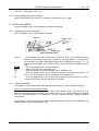
6.6.6. Location Based Scan
This operation controls avoid state for each department or site when the scanner is connecting
GPS unit. This works automatically by receiving the location data from GPS.
Figure 6-17 Receiving data from GPS unit
6.6.7. Temporary System Hold
*While it is in Temporary System Hold state, Priority Scan and Close Call function are not
performed.
The scanner make stop Scanning while reversing display by pressing [SYSTEM] key.
This state is called "Temporary System Hold".
This state maintains for 2 seconds.
For Internal Use Only
24
< UB375Z Operation Specification >
Ver. 1.09
When the user selected a system while the scanner is Temporary System Hold, the scanner
scans only the selected system.
6.6.8. Temporary Department Hold
The scanner make stop Scanning while reversing display by pressing [DEPT] key.
This state is called "Temporary Department Hold".
This state maintains for 2 seconds.
User can select a department while the scanner is Temporary Department Hold.
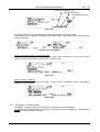
6.6.9. System Hold
Press [SYSTEM] key to goes to System Hold Mode.
While System Hold, the scanner scans only one system and scanner turn on HOLD icon.
Figure 6-18 System Hold
Press [SYSTEM] key to system scan, and other keys would work normally.
If it cannot scan the selected system, the scanner can’t go to System Hold Mode.
In Temporary System Hold, press [AVOID] key once to temporarily avoid a current system with
“Temporary Avoid” message.
In Temporary System Hold, press [AVOID] key twice in a second to permanently avoid the
current system with “Permanent Avoid” message.
Figure 6-19 Temporary Avoid
6.6.10. Department Hold
Press [DEPT] key to goes to Department Hold Mode.
While Department Hold, the scanner scans only one department and scanner turn on HOLD icon.
Press [DEPT] key to department scan, and other keys would work normally.
6.6.11. Quick System Select
Turn [Rotary / FUNC] knob after pressing [SYSTEM] key within 2 seconds to select a System.
During selecting systems, scanning is not performed.
The user can select from all Systems that have 1 or more Channels. A System belonging to turn
off Quick Key disappears in this selection.
When no operation lasts 2 seconds, returns to the previous mode.
6.6.12. Unit ID of TGID
Unit ID of TGID is transmitted at the beginning of a conversation. Unit ID is used in Motorola,
EDACS (WIDE/NARROW) and APCO P25 Standard, P25 One-Freq system.
For Internal Use Only
25
< UB375Z Operation Specification >
Ver. 1.09
When “Disp. Unit ID” menu is On, if the scanner receives a Unit ID, the scanner displays
“UID:xxx”. XXX means I-CALL ID.
6.6.13. Key Operation During Scan Mode
Refer to APPENDIX “Key Action List”. (UB375Z_KeyActionList_V0_15.pdf)
6.7. SCAN HOLD MODE
Press [CHANNEL] key in Scan Mode to go to Scan Hold Mode.
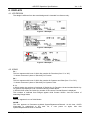
6.7.1. Display while Scan Hold Mode
The LCD display in Scan Hold mode is as follows.
frequency
channel name
Figure 6-20 Scan Hold
C162.2
HOLD
FM
ATT
Fx:
Sx:
: This appears when the channel has a CTCSS or DCS. In CTCSS/DCS Search
Mode or in All mode of Audio Type, if this is hit, the value blinks. If CTCSS/DCS is
set to lockout, the display alternates between the CTCSS/DCS data and "******". In
P25 NAC Search Mode, if a P25 NAC code is found, it will also be displayed in this
area.
: This icon appears while in Scan Hold Mode.
: These icons show the modulation type.
: This icon appears when the channel is set to “Attenuator On”.
: This icon appears with icons of Quick Key number for Favorites List (from “0” to
“99”). x shows current ten’s place of Quick Key for Favorites List.
: This icon appears with icons of Quick Key number for Systems (from “0” to “99”).
x shows current ten’s place of Quick Key for System.
6.7.2. General Operation
Turn [Rotary / FUNC] knob to select the channel, trunk frequency, TGID or search frequency.
Hold on a Channel in Conventional System:
The scanner displays System, Department name and Channel name. The Quick Key for
Favorites List assigned the Favorites List and the Quick Key for system assigned the System
that the channel belongs to is displayed. And the scanner monitors selected channel
continuously.
Press [Rotary / FUNC] knob to go to Function Mode and display the Favorites List Number Tag,
System Number Tag, Channel Number Tag.
For Internal Use Only
26
< UB375Z Operation Specification >
Ver. 1.09
Favorites List Number Tag
System Number Tag
Channel Number Tag
Figure 6-21
Press [9 / DISP] key in Function Mode to change the Display Line at Scan Mode.
The scanner in 3 Line Display can displays the System name, Department name, Channel name
with the large font.
Figure 6-22 3 Line Display
Hold on a Channel (TGID) in Trunked System
*If there are two or more sites in the system, same TGID will appear in each site. And the
scanner checks frequencies of current site for selected TGID.
Figure 6-23
Hold on Search Frequency
The scanner displays “Search with Scan”, System name, Department name and holding
frequency in Search Hold.
Figure 6-24
6.7.3. Site Hold on Trunked System
This feature is that the scanner works ID Scan or ID Search in a specified site.
To set Site Hold, user press [Rotary / FUNC] + [DEPT] key while a specified site. Then indicates
HOLD icon and indicates a site name.
For Internal Use Only
27
< UB375Z Operation Specification >
Ver. 1.09
Figure 6-25 Site Hold
6.7.4. Hold on Conventional System
Turn [Rotary / FUNC] knob clockwise to select next channel.
Turn [Rotary / FUNC] knob counterclockwise to select previous channel.
If the user turns [Rotary / FUNC] knob clockwise when it holds on last channel in the system, it
goes to next system. If the user turns [Rotary / FUNC] knob counterclockwise when it holds on
first channel in the system, it goes to previous system.
6.7.5. Hold on Trunked System
Turn [Rotary / FUNC] knob to select the channel (TGID).
Turn [Rotary / FUNC] knob clockwise to select next one and turn [Rotary / FUNC] knob
counterclockwise to select previous one.
If the user turns [Rotary / FUNC] knob clockwise when it holds on last channel, it goes to next
system or channel.
When it holds on a channel, the scanner displays a setting TGID. It does not go to any voice
channel. And it cannot avoid the displayed TGID.
6.7.6. Hold on TalkGroup ID from ID Search / ID Scan
The scanner monitors the held TGID continuously.
While monitoring the TGID already stored into the Memory, displays Favorites List Name,
System Name, Department Name, Channel Name and TGID.
And the numbers of Quick Key for current monitoring Favorites List and System appears.
While monitoring the TGID not stored into the Memory with ID Search, displays Favorites List
Name, System Name, Department Name, Channel Name and monitoring TGID.
And the numbers of Quick Key for current monitoring Favorites List and System appears.
Press [CHANNEL] key to resume ID Search or ID Scan.
6.7.7. Change Site Avoid Condition
User can set easily On/Off for Site Avoid Condition.
In a Trunked System,
1. Press [Rotary / FUNC] key then [DEPT] key goes to Site Hold mode.
In Site Hold mode,
2. Press [DEPT] key then [AVOID] → Toggle Site avoid condition On/Off
3. Press [DEPT] key then [Rotary / FUNC] knob → Rotate all sites in the system.
4. Press [Rotary / FUNC] key then [DEPT] key to exit Site Hold mode.
Note: User can set also On/Off for Site Avoid Condition with Menu.
6.7.8. Direct Entry
*The scanner receives nothing in this mode.
The user can store quickly a frequency or a TGID by [0] - [9] key and [.no] key. And the user
can direct access that you want to input number tag.
For Internal Use Only
28
< UB375Z Operation Specification >
Ver. 1.09
6.7.8.1. Store Frequency
*In this operation, a frequency cannot store to trunked System.
To quickly store a frequency into a channel for conventional system, the user enters the
frequency including the decimal point using the keypad, then presses [E yes] key. The scanner
prompts "Quick Freq Save?".
*If the user presses [SYSTEM] / [DEPT] / [CHANNEL] key without pressing [E yes] key, the
scanner goes to Quick Search Hold Mode at the entered frequency. (See: 6.11.2. Go to Quick
Search Hold Directly)
6.7.8.2. Store TGID
To quickly store a TGID into a channel, the user enters the TGID using numeric key and decimal
key. Then press [E yes] key, the scanner prompts "Quick TGID Save?".
Figure 6-26 Store TGID
If the user press [AVOID] key without pressing [E yes] key, the scanner goes to ID Search Hold
Mode directly and the TGID is not stored. When the user inputs illegal ID, the scanner displays
“Bad TGID Press Any Key” and sounds error tone.
If the user presses [E yes] key, the scanner creates "Quick Save Department" at the current
system and stores this data there.
If the user presses [.no] key, the user can select a system to store this data.
The user selects the system* and the department. And this data is stored.
*In system selection, the scanner displays only the system whose inputted ID format matched.
The ID format and system type relation are shown to the following.
Table 6-1
Input TGID (n: number)
nnn-nn
nnnn-n
nnnnnnnnnnn-n
nnnnn
nnnnn
nn-nnn
nnnn-nnn-nn-nnn
n-nn-
System Type
Motorola Systems
(Type I, Type II)
P25 Systems
EDACS Systems
*Only AFS Format is allowed for
Direct Entry except for I-Call ID.
LTR Systems
*For details of TGID, please see: 7.2. TGID FORMAT FOR TRUNKED SYSTEM.
Once saved, the scanner allows the user to change the Channel settings at menu location “Edit
Channel”. Press [SYSTEM] / [DEPT] / [CHANNEL] key to go to ID Scan Hold and the scanner
tries to acquire the Control Channel for current site or first site of the System. If successful, it
then holds on the stored Channel. Otherwise, it displays "Finding CtrlChan" (and Channel
Name).
For Internal Use Only
29
< UB375Z Operation Specification >
Ver. 1.09
6.7.8.3. Direct Access
Use this feature to quickly access a channel with number tags. A favorite, system or channel
number tags can be set in the menu. However, if user set a channel number tag that has already
existed in the same system, or user set a system tag that has already existed in other systems
(include scan system), then a warning message will be displayed “Number Tag Exists Accept?
(Y/N)”. User press [E yes] key to set the same number tag, or press [.no] key to input a new
number tag.
To jump to a tagged channel from HOLD mode, enter the favorite number tag, the system
number tag and the channel number tag with decimal point, then press [CHANNEL] key, the
scanner goes to Scan Hold Mode at the entered number tag.
For example
If user wants to select Channel C, press [1] [.no] [3] [.no] [1] [0] [CHANNEL].
Favorite A
(Number tag = 1)
System A
(Number tag = 3)
System B
(Number tag = 5)
Channel A (Number tag = 1)
Channel B (Number tag = 5)
Channel C (Number tag = 10)
Channel D (Number tag = 10)
Channel E (Number tag = 5)
Channel F (Number tag = 1)
Favorite Number Tag
System Number Tag
Channel Number Tag
Figure 6-27 Enter Number Tag
User does not have to enter the favorite and the system number tag to select a channel in the
current favorite.
When the scanner is holding on System A of Favorite A, press [.no] [.no] [1] [0] [CHANNEL] to
select Channel C.
If user press only favorite and system number tag with decimal point, the scanner select the first
channel of the system. Pressing [1] [.no] [5] [.no] [CHANNEL], Channel D is selected.
If no such system number tag exist, the scanner sounds error tone and displays as follows;
Figure 6-28
When the user inputs illegal channel number tag, the scanner displays “CH Number Tag
XXX.XXX is not Stored Press Any Key” and sounds error tone.
6.7.9. Key Operation During Scan Hold Mode
Refer to APPENDIX “Key Action List”. (UB375Z_KeyActionList_V0_15.pdf)
For Internal Use Only
30
< UB375Z Operation Specification >
Ver. 1.09
6.8. PRIORITY SCAN
There are two kinds of Priority Scan.
6.8.1. Priority Scan
This works in Scan Mode or Scan Hold Mode when the Priority Scan setting is on. In this
condition, " PRI" icon appears.
Figure 6-29
When the scanner is scanning a conventional system, it interrupts every interval time to check
Priority Channels (P-Ch) of all unavoided conventional Systems for activity. If there are many PChs, Priority Scan interrupts normal scanning for a long time.
Although any conventional frequency is set as a priority channel, the scanner is unable to scan
over 100 channels at once. If unavoided priority channels are over 100, the first 100 channels will
be scanned for priority scanning but others won’t.
User can change max priority channel.
The priority of P-Chs applies to Quick Key for System.
The highest priority is P-Ch to which Quick Key for System belongs to "0". And the lowest priority
is its to which Quick Key for System belongs to “99”.
The priority of P-Ch in the group follows the turn that creates the channel.
If there is no priority Channel or all Priority Channels are avoided, the scanner displays "Priority
Scan No Channel" and sounds Error Tone. The scanner cannot work the Priority Scan. Then the
scanner restarts normal scanning by pressing any key. And the setting of Priority Scan is set to
off automatically.
Figure 6-30
6.8.2. Key Operation During Priority Scan
Key operations are same as Scan Mode and Scan Hold Mode.
See: 6.6.13. Key Operation During Scan Mode and 6.7.9. Key Operation During Scan Hold Mode.
For Internal Use Only
31
< UB375Z Operation Specification >
Ver. 1.09
6.9. PRIORITY ID SCAN
6.9.1. Priority ID Scan
Priority ID Scan works in ID Scan/Search Mode or ID Scan/Search Hold Mode when the Priority
ID Scan setting is on.
This works on the Motorola and EDACS (Wide, Narrow), LTR, P25 Standard systems.
This function is very similar to conventional priority although there is no “interrupt” during the
transmission. Priorities are checked in between transmissions.
The scanner can receive the priority ID when trunking ID delay condition.
NOTE: Motorola system can receive priority ID while scanner is staying V-Ch.
The scanner is scanning unavoided priority IDs.
The priority of P-IDs applies to Quick Key for System.
The highest priority is P-ID to which Quick Key for System belongs to "0".
And the lowest priority is P-ID to which Quick Key for System belongs to “99”.
6.9.2. Key Operation During Priority ID Scan
Key operations are same as ID Scan Mode and ID Scan Hold Mode.
See: 6.6.13 Key Operation During Scan Mode and 6.7.9 Key Operation During Scan Hold Mode.
For Internal Use Only
32
< UB375Z Operation Specification >
Ver. 1.09
6.10. SEARCH MODE
There are Custom Search and Quick Search in Search Mode.
6.10.1. Display while Search Mode
The LCD display in Search mode is as follows.
the number of the range currently searched
a search range name.
the searching direction
Figure 6-31
NFM : These icons show the modulation type.
SCR : This icon appears when one or more Broadcast Screen Band is set to On.
: This icon shows strength of the signal from 0 to 5.
6.10.2. General Operation
Press [SYSTEM] / [DEPT] / [CHANNEL] key to go to Search Hold Mode with current frequency.
6.10.3. Custom Search
In this searching, the user can turn on or off custom range number by [0] - [9] key. But it cannot
turn off the last one Custom Range. If try it, the scanner sounds Error Tone. The scanner only
searches turned on custom ranges. And searching range number blinks.
Figure 6-32
At first, it starts from lowest frequency of the turned on range of the minimum number in
ascending order. Or, it starts from highest frequency of the turned on range of the maximum
number in descending order. While searching, turn [Rotary / FUNC] knob to change searching
direction.
If the scanner finds a transmission, it stops on the frequency and displays the frequency.
While monitoring the transmission, turning [Rotary / FUNC] knob to resume searching.
Press [AVOID] key once to avoid the frequency temporarily. The scanner displays “Temporary
Avoid".
Press this key twice in a second to avoid the frequency permanently. The scanner displays
“Permanent Avoid”.
Then resume searching from the next frequency.
If the user turns off current searching or monitoring range number, the scanner searches from
next range.
The scanner stays on the frequency until the delay time expires even if the transmission ends.
For Internal Use Only
33
< UB375Z Operation Specification >
Ver. 1.09
When the scanner enters to Custom Search by select "Custom Search" at Menu, frequency is
initialized and it starts searching. When the searching direction is ascending order, the scanner
searches from lowest frequency of the turned on Range of the minimum number. When the
searching direction is descending order, the scanner searches from highest frequency of the
turned on Range of the maximum number.
When the scanner returns to Custom Search by cancel Menu Mode, the scanner will resume
searching from previous frequency with previous direction.
However, if the limit settings of one of Custom Ranges are changed and previous frequency
becomes out of limit, it searches from lowest frequency of previous Range for ascending order or
from highest frequency of previous Range for descending order.
Custom Search Temporary Hold :
The scanner searches only for selected range after pressing [SYSTEM] / [DEPT] key within 2
seconds.
And when the scanner return to Normal Mode, it searches for all range.
Custom Search Range Select :
The user can select the range by turning [Rotary / FUNC] knob after pressing [SYSTEM] /
[DEPT] key within 2 seconds to select the range.
When the scanner returns to Normal Mode, it searches from the selected range.
If the user selects a range that turned off, the scanner turns on the range and starts searching
from the range.
6.10.4. Quick Search
Quick Search searches all band coverage.
The user can start Quick Search by pressing [E yes] key in Function Mode during Scan Mode,
Close Call, Custom Search, Weather Scan Mode and Tone-Out Mode, the scanner prompts the
user with "Quick Search?".
If the user presses [E yes] key, the scanner starts Quick Search.
If the user presses [.no] key, the scanner goes to Menu Mode about searching at “Search for...”.
If the user presses [SYSTEM] / [DEPT] / [CHANNEL] key, the scanner goes directly to Quick
Search Hold Mode.
Pressing [AVOID] key cancels the prompt and it returns to previous mode.
6.10.4.1. Quick Search for frequency
The scanner searches from the current channel frequency when the Quick Search starts from
monitoring / holding conventional systems, Custom Search etc, Close Call Mode, Weather Scan
Mode and Tone-Out Mode.
The range of this searching is all range of the scanner.
Turn [Rotary / FUNC] knob to change the searching direction.
Figure 6-33
If the scanner finds a transmission, it stops on the frequency and second line displays the
frequency.
While monitoring the frequency, press [SYSTEM] / [DEPT] / [CHANNEL] key to make Hold Mode.
While monitoring the frequency, turning [Rotary / FUNC] knob to resume searching.
Press [AVOID] key once to avoid the frequency temporarily. The scanner displays "Temporary
Avoid".
For Internal Use Only
34
< UB375Z Operation Specification >
Ver. 1.09
Press this key twice in a second to avoid the frequency permanently. The scanner displays
“Permanent Avoid”.
Then resume searching from the next frequency.
6.10.5. Key Operation During Search Mode
Refer to APPENDIX “Key Action List”. (UB375Z_KeyActionList_V0_15.pdf)
6.11. SEARCH HOLD MODE
Press [SYSTEM] / [DEPT] / [CHANNEL] key in Search Mode to go to Search Hold Mode and the
scanner holds on the current frequency.
6.11.1. General Operation
The scanner monitors the frequency continuously.
In Quick Search Hold Mode, the scanner displays as follows;
Figure 6-34
Turn [Rotary / FUNC] knob to select the frequency.
Press [AVOID] key once to avoid the frequency temporarily. The scanner displays "Temporary
Avoid".
Press this key twice in a second to avoid the frequency permanently. The scanner displays
“Permanent Avoid”.
Press [AVOID] key on the avoided frequency to unavoid it. The scanner displays “Stop
Avoiding”.
Long press [AVOID] key to unavoid all frequency of search.
Press [SYSTEM] / [DEPT] / [CHANNEL] key to restart searching.
6.11.2. Go to Quick Search Hold Directly
When the scanner holds on in any Hold Mode, the user can go to Quick Search Hold Mode
directly.
The user inputs a frequency by [0] - [9] key and [.no] key. And presses [SYSTEM] / [DEPT] /
[CHANNEL] key.
Then the scanner goes to Quick Search Hold Mode directly with the inputting frequency.
By this feature, the user can monitor any frequency quickly.
6.11.3. Direct Entry
Enter the frequency or TGID by pressing numeric keys and decimal key, then press [E yes] key
to store entered data quickly.
6.11.4. Key Operation During Search Hold Mode
Refer to APPENDIX “Key Action List”. (UB375Z_KeyActionList_V0_15.pdf)
For Internal Use Only
35
< UB375Z Operation Specification >
Ver. 1.09
6.12. CLOSE CALL MODE
The basic Close Call feature allows the scanner to immediately lock onto a transmission above
threshold signal strength.
The way the scanner treats a Close Call is based on settings of the menu at Srch/CloCall Opt
and Close Call
6.12.1. Display while Close Call Mode
Figure 6-35
:
This icon indicates when the Close Call Mode is “CC Priority”.
:
This icon indicates when the Close Call Mode is “CC DND”.
6.12.2. Close Call Search
*Close Call function does not work while it is in Temporary Hold or System Select of Scan Mode,
one of Weather Scan Mode and Tone-Out Mode.
**While the scanner is staying on repeater frequency or reverse frequency, it does not prompt
any new found Close Call.
The scanner checks Close Call transmission while scanning or searching every 2 seconds.
If Close Call frequency is found, the scanner alerts the user according to the setting of Set CC
Alert.
CC DND is set:
The scanner does not operate this function during receiving channel or frequency.
“DND” means “Do Not Disturb”.
CC Priority is set:
The scanner operates this function regardless of receiving signal or not.
Figure 6-36
Turning [Rotary / FUNC] knob to ignore the Close Call and return to previous state.
Press [SYSTEM] / [DEPT] / [CHANNEL] key to go to Close Call Hold Mode of the frequency.
Press other keys to listen the detected frequency.
Monitoring Close Call Transmission:
While monitoring Close Call transmission, the scanner displays "Close Call" and monitoring
frequency on LCD. The modulation is also displayed.
For example, if the scanner finds a transmission on 462.7125 MHz, it displays as follows.
For Internal Use Only
36
< UB375Z Operation Specification >
Ver. 1.09
Figure 6-37
In this monitoring condition, the scanner does not check other Close Call transmission.
Press [SYSTEM] / [DEPT] / [CHANNEL] key while monitoring condition to go to Close Call Hold.
Turning [Rotary / FUNC] knob to cancel the monitoring condition. Then the scanner checks valid
CC Bands from next one to 800MHz+ Band. If it finds Close Call transmission, the scanner
informs again. Otherwise, it returns to previous mode.
Press [AVOID] key once to avoid the frequency temporarily. The scanner displays "Temporary
Avoid".
Press this key twice in a second to avoid the frequency permanently. The scanner displays
“Permanent Avoid”.
Then resume searching from the next frequency.
The scanner stays on the frequency until the Delay time expires even if the transmission ends.
Then the scanner checks valid CC Bands from next one to 800MHz+ Band. If it finds Close Call
transmission, the scanner informs again. Otherwise, it returns to previous mode.
If all the bands are set to Off at “Set CC Bands”, the scanner does not check any Close Call
transmission. If so, the scanner displays “Close Call” and "All Band Off!" and sounds Error Tone
when it tries to perform the Close Call function.
Then the scanner sets CC Mode to Off of “Set CC Mode”
Figure 6-38
The scanner stays at this state.
In this state, press any key to turn all the close call bands on.
6.12.3. Close Call Only
The scanner performs this by menu at "Close Call Only". Or, long press SQ knob to perform this
quickly.
The scanner only tries to find a Close Call transmission.
The scanner will be displayed “Close Call”, and the close call meter that indicates the
transmission signal level of each band will be shown on LCD.
Or if Attenuation, Broadcast Screen or Repeater Find settings of Srch/CloCall Opt are on, each
icon is displayed.
Figure 6-39
For Internal Use Only
37
< UB375Z Operation Specification >
Ver. 1.09
If the scanner has already received Close Call and the user press [SYSTEM] / [DEPT] /
[CHANNEL] key, the scanner holds on latest Close Call hit frequency. Or if it has not hit Close
Call yet, it is ignored and sounds Error Tone.
Press numeric key from [0] key to [6] key to switch each band on or off which also can be done
in menu "Set CC Bands".
If the scanner found a Close Call transmission, the scanner informs the user of "CC Found!" and
"Press Any Key".
Figure 6-40
Press any key to see found frequency. And user can listen found Close Call.
Figure 6-41
Press [SYSTEM] / [DEPT] / [CHANNEL] key to go to Close Call Hold Mode.
In Close Call Only Mode, press [MENU] key in Function Mode to go to Menu of Close Call at
"Close Call".
Monitoring Close Call Transmission:
In this monitoring state, the scanner does not check other Close Call transmission.
Press [SYSTEM] / [DEPT] / [CHANNEL] key while monitoring condition to go to Close Call Hold.
While the scanner is monitoring the transmission, turning [Rotary / FUNC] knob to resume
searching Close Call.
If all the bands are Off at "Set CC Bands", the scanner cannot check any Close Call transmission.
If so, the scanner displays "All Band Off!" and sounds Error Tone. In this state, press any key to
turn all the close call bands on.
6.12.4. Close Call Hold
In Close Call Hold state, the scanner holds on the current Close Call hit frequency even if the
transmission ends.
The scanner displays HOLD icon and the holding frequency. The modulation is displayed.
For example, if the scanner finds a transmission on 433.0000 MHz, it displays as follows.
Figure 6-42
In this condition, the scanner does not check other Close Call transmission.
For Internal Use Only
38
< UB375Z Operation Specification >
Ver. 1.09
While it holds on a frequency, turning [Rotary / FUNC] knob goes to Quick Search Hold with the
holding frequency. And Close Call Mode will be set to off.
Press [SYSTEM] / [DEPT] / [CHANNEL] key to return to the previous state*. If Close Call
transmission is found again, the scanner informs again.
*Previous state is one of these modes: Scan Mode, Scan Hold Mode, each Search Mode, each
Search Hold Mode, Close Call Only Mode.
6.12.5. CC Bands
This setting controls the band filtering used during Close Call operation.
The user can turn on or off the following bands.
VHF Low 1
VHF Low 2
Air Band
VHF High 1
VHF High 2
UHF
800MHz+
On
Off
:
:
:
:
:
:
:
On/Off
On/Off
On/Off
On/Off
On/Off
On/Off
On/Off
:
:
:
:
:
:
:
25.0000
54.0000
108.0000
137.0000
225.0000
320.0000
758.0000
849.0125
894.0125
1240.0000
53.9800 MHz
- 107.9000 MHz
- 136.9916 MHz
- 224.9800 MHz
- 319.9750 MHz
- 512.0000 MHz
- 823.9875 MHz
- 868.9875 MHz
- 960.0000 MHz
- 1300.0000 MHz
The scanner check Close Call in this Band.
The scanner does not check this Band.
6.12.6. Key Operation During Close Call Only Mode
Refer to APPENDIX “Key Action List”. (UB375Z_KeyActionList_V0_15.pdf)
For Internal Use Only
39
< UB375Z Operation Specification >
Ver. 1.09
6.13. WEATHER SCAN MODE
User can start scanning for 7 Weather Channels by menu operation. Another operation is that
press and hold [6 / WX] key in function mode starts this mode quickly from other hold modes.
The scanner scans for 7 Weather Channels normally, or alerts when a 1050 Hz Weather Alert
Tone or a SAME Weather Alert is broadcast on a Weather Channel.
It cannot avoid any Weather Channel.
*Close Call function does not work while it is in one of Weather Scan Mode even if "Set CC
Mode" is “CC DND” or “CC Priority”.
6.13.1. Normal Weather Scan
The scanner starts this when the user selects Weather Scan in Menu Mode at “WX Operation”.
The scanner scans 7 Weather Channels normally.
Figure 6-43
When it finds a broadcast, it stops on the Channel.
Figure 6-44
If the signal is lost, the scanner resumes scanning for Weather Channels.
While this scanning, the scanner does not pay attention to 1050 Hz Weather Alert Tone and
SAME Weather Alert.
6.13.2. Weather Alert Scan
The scanner starts this when the user selects one of Weather Alert function in Menu Mode at
“Weather Alert”.
The scanner scans 7 Weather Channels and alerts when it detects a 1050 Hz Weather Alert
Tone or a SAME Weather Alert.
Figure 6-45
If it is set to Alert Only, the scanner immediately sounds a Weather Alert Siren (for Weather
Alert Tone) and displays "Warning WX" and "WX Alert" when it detects the 1050 Hz Weather
For Internal Use Only
40
< UB375Z Operation Specification >
Ver. 1.09
Alert Tone. This Siren sounds as long as 1050 Hz Weather Alert Tone is broadcasted, or
pressing any key to stop the Siren. Then opens squelch and remains on the Weather Channel.
If the user presses any key, the scanner becomes WX Scan Hold Mode and releases the mute.
Figure 6-46
If it is set to one of SAME Groups, the scanner attempts to decode the SAME data packets that
precede the Alert Tone. Then the scanner sounds a Weather Alert Siren (for Warning, Watch or
Advisory) when received County is the same as the programmed data. The scanner displays
warning level as "Warning WX", "Watch WX" or "Advisory WX" and it displays decoded Event
Code. (See: 7.10. CEA2009-SAME EVENT CODE for displayed characters)
The user presses any key, the scanner becomes Weather Scan Hold Mode and releases the
mute and remains on the Weather Channel.
If the scanner decodes the EOM (= End of Message) in Weather Alert Scan Mode, it returns to
mute condition. However if the scanner is already in Weather Scan Hold Mode, it will not mute by
decoding the EOM.
For example, the scanner displays as follows when it decodes the SAME data that has an Event
Code of "EAN".
Figure 6-47
If it is set to All FIPS, the scanner sounds a Weather Alert Siren (for Warning, Watch or
Advisory) when it decodes the SAME data packets that precede the Alert Tone. It displays
warning level and Event Code.
Then opens squelch and remains on the Weather Channel.
*When the scanner detects the SAME data, it sounds each Weather Alert Siren for a maximum
of 8 seconds. But the user can suspend the siren by pressing any key.
*When the scanner detects the 1050 Hz Weather Alert Tone, it sounds Weather Alert Siren as
long as 1050 Hz Weather Alert Tone is broadcasted, or press any key to stop the Siren.
6.13.3. Weather (Alert) Scan Hold
Press [SYSTEM] / [DEPT] / [CHANNEL] key during Weather (Alert) Scan to hold on the current
Weather Channel.
The scanner displays HOLD icon and displays “WX Scan” or “ WX Alert”, and it displays Channel
Number and frequency.
Then the scanner checks only the Channel.
For Internal Use Only
41
< UB375Z Operation Specification >
Ver. 1.09
Figure 6-48
The scanner does not sound until it detects the 1050 Hz Weather Alert Tone or decodes the
SAME data in Weather Alert Scan Hold. See: 6.13.2. Weather Alert Scan for operation when it
detects the 1050 Hz Weather Alert Tone or decodes the SAME data.
Press [SYSTEM] / [DEPT] / [CHANNEL] key again to return to Weather (Alert) Scan.
6.13.4. Weather Alert Priority (WX Alt Priority)
The scanner interrupts a scanning or searching every 5 seconds and checks whether there is
1050 Hz Weather Alert Tone on Weather Channels.
If it found, the scanner jumps to the Weather Channel and sounds Weather Alert Siren (for
Weather Alert Tone). Pressing any key stops this Siren.
After the Siren stops, the scanner opens squelch and remains on the Weather Channel.
If the user presses any key again, it goes to Weather Scan Hold Mode.
*WX Alt Priority function does not work while it is in one of Weather Scan Mode and ToneOut Mode.
6.13.5. Key Operation During Weather (Alert) Scan Mode
Refer to APPENDIX “Key Action List”. (UB375Z_KeyActionList_V0_15.pdf)
6.14. TONE-OUT MODE
Select “Tone-Out Standby” in "Tone-Out for..." in menu mode.
Note:In this function, Close Call and WX Priority don't operate.
6.14.1. Display while Tone-Out Mode
Tone-Out Standby
Tone-Out channel name
Tone-Out Standby Status
Tone-Out channel
number
Tone A and B frequency
Figure 6-49 Tone A = 1000Hz Tone B = 2000Hz
Figure 6-50 Tone A = B = 0.0Hz
FM
ATT
IFX
: These icons show the modulation type.
: This icon shows the attenuator status of current channel. When Global attenuator is on,
this icon blinks.
: This icon shows when current channel is IF exchange frequency.
For Internal Use Only
42
< UB375Z Operation Specification >
Ver. 1.09
6.14.2. Tone-Out Standby Mode
When not both of Tone A and Tone B are set as 0.0Hz, the scanner starts the Tone-Out Standby.
During monitoring the Tone-Out frequency, the speaker is muted until Tones are detected.
For two-tone pages, enter a value for Tone A and Tone B.
For single-tone pages (alert by a single short tone), enter the tone value for Tone A and "0" for
Tone B.
For group tones (alert by a single long tone), enter "0" for Tone A and the tone value for Tone B.
When user sets the tone value for Tone A and Tone B, if a transmission is detected, the scanner
checks whether the tone is corresponding to Tone A.
If the first tone matches Tone A, the scanner confirms that the tone is present for more than
250ms.
Then the second tone is confirmed whether it detects second tone less than 500ms.
And if the second tone matches Tone B and the tone is present for more than 100ms, the
scanner opens squelch and sounds alert tone, alert light that user set in the menu. Then the
scanner goes to Tone-Out Hold Mode.
When the user sets the tone value for Tone A and "0" for Tone B, the scanner confirms that
Tone A matches the first tone and is present for the following range.
Tone A : 1.25 - 3.75 seconds
Then, the scanner goes to Tone-Out Hold Mode.
Or, when the user sets the "0" for Tone A and the tone values for Tone B, the scanner confirms
that Tone B matches the first tone and it is present for more than 3.75 seconds.
Then, the scanner goes to Tone-Out Hold Mode.
Multi-Channel Monitoring
The scanner can check plural tone combination for channels that settings are the same. For this
operation, set the same setting to frequency, Modulation and Attenuator.
For example, the scanner can check tone combination from CH 1 to CH3 at the same time when
the scanner sets the following settings.
CH 1
CH 2
CH 3
CH 4
CH 5
CH 6
Frequency (MHz)
137.0000
137.0000
137.0000
137.0000
137.0000
138.0000
Modulation
Auto*(NFM)
Auto*(NFM)
NFM
NFM
FM
Auto*(NFM)
Attenuator
Off
Off
Off
On
Off
Off
Tone A (Hz)
1000.0
2200.0
1500.0
1800.0
2000.0
1000.0
Tone B (Hz)
2000.0
3200.0
2500.0
2800.0
3000.0
2000.0
*Modulation setting "Auto" follows the initialization of Band Coverage. However, when
modulation of the frequency in 1.1. BAND COVERAGE is not FM or NFM, it operates
compulsorily as FM. And “Auto “ is compared as NFM or FM with other channel’s setting.
*The scanner detects the Tone on the channel that its number is the smallest if the user set
same tone in multi-channel.
While Tone-Out Standby Mode for Multi-Channel Monitoring, the scanner switches the channel
display each 2 seconds. But the scanner checks all Tones for Multi-Channels simultaneously.
When one of the tone combinations is detected, it goes to Tone-Out Hold Mode.
6.14.3. Tone-Out Search Mode
When both of Tone A and Tone B are set as 0.0Hz, this channel will be treated as a Tone-Out
Search channel. The scanner starts the Tone-Out Search. During monitoring the Tone-Out
frequency, the speaker is muted until Tones are detected.
In this Tone-Out Search mode, if a transmission is detected, the scanner starts to check twotone pages, single-tone pages and group tones.
For two-tone pages, Tone A must be present more than 250ms, Tone B must be present more
than 100ms, and the time gap between Tone A and Tone B must less than 500ms.
For single-tone pages, Tone must be present between 1.25-3.75 seconds.
For group tones, Tone must be present more than 3.75 seconds.
For Internal Use Only
43
< UB375Z Operation Specification >
Ver. 1.09
If one kind of these tones is detected, the scanner begins to check whether it has been registed
in another tone-out channel with the same setting to frequency, Modulation and Attenuator. If it
has been registed, the scanner goes to Tone-Out Hold Mode with the registed channel number.
If not, the scanner goes to Tone-Out Hold Mode with current Tone-Out search channel number.
Note: Tone-Out Search channel will not be treated as Multi-Channel even if it has the same
setting of frequency, Modulation and Attenuator with other channels. When in Tone-Out
Search Mode, scanner would not switches the channel display each 2 seconds for the
Multi-Channel.
6.14.4. Tone-Out Hold Mode
The user can hear the transmission in Hold Mode. When the transmission ends and the delay
time expired, the scanner returns to standby condition or search condition. Or pressing
[SYSTEM] / [DEPT] / [CHANNEL] key also returns to standby condition or search condition.
Figure 6-51
The scanner displays the following in Tone-Out Hold Mode.
User can change to Hold Mode from Standby Mode or Search Mode by pressing [SYSTEM] /
[DEPT] / [CHANNEL] key. Tone-out Hold Mode has no timeout.
If the scanner detected new tone-out sequential that has not been register yet, indicates Tone
A/B Frequency.
Figure 6-52 new tone-out sequential
User can return to the Tone-Out Search Mode by pressing [SYSTEM] / [DEPT] / [CHANNEL] key.
Press [E yes] key, user will be prompted whether save the new detected tone-out sequential.
Figure 6-53
Press [E yes] key to save the new tone-out sequential and move to tone-out setting menu "ToneOut Settings". Press [.no] key to cancel the new tone-out sequential and move to tone-out
setting menu "Tone-Out Settings"
Note: If the user changes the Channel by turning [Rotary / FUNC] knob when in Hold Mode,
Hold condition is canceled and it moves to next channel.
For Internal Use Only
44
< UB375Z Operation Specification >
Ver. 1.09
6.14.5. Key Operation During Tone-Out Mode
Refer to APPENDIX “Key Action List”. (UB375Z_KeyActionList_V0_15.pdf)
6.14.6. Update Location Information
Update Location Information of the scanner execute as follows;
1. When Baud Rate in Serial Port menu is Off
- the scanner can not receive data from GPS unit.
- the scanner use a location information by ZIP code.
2. When Baud Rate in Serial Port Serial is not Off
- The scanner update the location information by GPS unit even if the scanner has a location
information by ZIP code.
6.15. DISCOVERY FEATURE
The discovery features make it easier than ever to find new channels using the scanner. This
feature includes as follows;
- Trunking Discovery Mode
- Conventional Discovery Mode
- Review Discovery Mode
To access the discovery features, select Discovery Mode from the Discovery Menu.
Figure 6-54 Trunking Discovery Menu
The scanner have Auto Store feature.
If user set “On” of Auto Store, the scanner searches TGID and stores new found ID’s into a
specified System. The storing name by Auto Store as follows;
when selected Trunking Discovery
- Favorites List name : Trunking Discovery
- System name : selected System Name
- Site name : selected Site Name
- Department name : Run Folder Name
when selected Conventional Discovery
- Favorites List name : Conventional Discovery
- System name : Session Name
- Department name : Run Folder Name
6.15.1. Trunking Discovery Mode
Trunking Discovery Mode allows user to monitor a trunked radio system, logging system channel
activity and recording the audio for channels not currently in the database.
Before using this mode, set user’s location and range, and choose the database(s) to use for
scanning.
To access the Trunking Discover Mode, select Trunking Discovery from the Discovery Menu.
For Internal Use Only
45
< UB375Z Operation Specification >
Ver. 1.09
Next, select to create a new discovery mode settings by selecting New Discovery Session, or
open a previously created sessions.
Select System to select the trunked system to use, then enter the first few letters of the system.
Figure 6-55 Enter a few letters
Figure 6-56 Selected System
Select the System to use for the session by pressing [E yes] key. Then select the site to use for
the session. For multisite systems, more than one site will appear. Enter a name for the session.
Figure 6-57 New Session
To start the discovery session, select “Start Discovery” and press [E yes] key.
6.15.2. Conventional Discovery Mode
Conventional discovery mode lets user monitor a range of frequencies, logging frequencies with
activity and recording the audio for frequencies that are not already known to be in use in user’s
area so that user can more easily identify the users. This includes frequencies used
conventionally as well as in trunked radio systems.
Before using this mode, set user’s location and range, and choose the database(s) to use for
scanning.
To access the Conventional Discovery Mode, select Conventional Discovery Mode from the
Discovery Menu.
Figure 6-58 Conventional Discovery Menu
Next, select to create a new discovery mode settings by selecting New Discovery Session, or
open a previously created sessions.
For Internal Use Only
46
< UB375Z Operation Specification >
Ver. 1.09
Figure 6-59 Input Session Name
Figure 6-60 Select Menu
To start the discovery session, select “Start Discovery” and press [E yes] key.
User have to set Lower and Upper Frequency in Set Limit Frequencies menu before Start
Discovery
Figure 6-61 Conventional Discovery
6.15.3. Review Discovery Mode
In the review discovery mode, user can review the results of discovery mode runs, resume runs,
or restart saved discovery sessions.
From the Discovery menu, select Review Discovery Mode.
For Internal Use Only
47
< UB375Z Operation Specification >
Ver. 1.09
Figure 6-62 Review Discovery Menu
6.15.3.1. Review Discovery
After selecting the Review Discovery Menu, select Trunking Discovery Results or Conventional
Discovery Results.
Figure 6-63 Review Discovery
A list of all previous discovery sessions appears. Select the session name to review it.
Figure 6-64 Discovery Results
The Review menu appears for this session.
If the current database selection does not include the system used for the discovery session,
“Restart this Run” and “Resume this Run” options are not available. Then displays message as
follows;
Figure 6-65
6.15.3.2. Review Run Results
Figure 6-66
For Internal Use Only
48
< UB375Z Operation Specification >
Ver. 1.09
Select Review Run Results.
A summary list of all hits appears on the screen. In this view, hits on the same channel are
grouped into one record.
Figure 6-67 Summary or Detail
Select Summary or Detail, and select a recording session. Then indicates Play or Information.
Hits for found channels include a recording of the audio during that hit. Select a line to play back
the audio.
Recording session with no audio include “0 sec ...” character in Figure 6-68 Recording Session
(0 sec).
Figure 6-68 Recording Session (0 sec)
In this view mode, all hits are shown in the order they occurred.
6.16. Wi-Fi CONNECTION
The scanner have 2 kind of Wi-Fi connection. First, Access Point Mode, second Infrastructure
Mode.
6.16.1. Access Point Mode
This mode is able to connect with Client units up to 5 clients.
If user use this mode, need some setting parameter as follows;
- SSID
- Security type
- Password
The scanner have already default setting value of these parameters.
User have to set each parameters for “Access Point Mode” in “Wi-Fi Setup” Menu.
Supported Security Types are “Open” and “WPA/WPA2”.
Refer to APPENDIX “Menu Tree Specification”. (UB375Z_MenuTreeSpecification_V0_15.pdf)
6.16.2. Infrastructure Mode
This mode is able to connect to Access Point unit.
If user use this mode, need a setting password basically. In a few case, there is no password
with Access Point unit.
Supported Security Types are “Open”, “WPA/WPA2” and “WEP”.
User set password for Access Point unit in “Infrastructure Mode” in “Wi-Fi Setup” Menu.
For Internal Use Only
49
< UB375Z Operation Specification >
Ver. 1.09
Refer to APPENDIX “Menu Tree Specification”. (UB375Z_MenuTreeSpecification_V0_15.pdf)
6.17. AUDIO RECORD / REPLAY
The scanner can record a received signal. The scanner has 2 kinds of record type, the Inner
Record and the User Record.
- Inner Record
: works when the scanner does not work the User Record.
- User Record
: works with ordering Start Record or Stop Record by user.
Inner Record
This feature works with a received signal whenever does not work the User Record.
To replay a recorded signal, user press [REPLAY] key.
User Record
To record a received signal, user press [Rotary / FUNC] + [REPLAY / RECORD] key. Then
indicates the confirmation message. If user press [E yes] key, starts the User Record feature.
To replay a recorded signal, user have to stop the User record feature. After that, press and hold
[REPLAY] key in function mode, then indicates Review Recordings List. User can select a
recorded session from this list.
Note: ・These Record feature does not work simultaneously. And the scanner can not replay
while the scanner records a received signal.
・No inner/user recording when monitor weather mode.
・When WX Alert mode and the scanner received an alert event, it starts recording.
・In WX monitor or Alert mode, [REPLAY] key goes to "Review WX Alerts" menu.
・In "Review WX Alerts", user can replay the selected alert recording.
・Received alerts are removed after the alert time expired.
6.18. REPEATER FIND
This feature sets whether the scanner attempts to locate the transmission on a repeater output
frequency when it detects a transmission on a common repeater input frequency.
(See 7.9 REPEATER FREQUENCY LIST)
On
The scanner automatically applies repeater reverse to detected transmissions. If the
scanner can detect the transmission on the output frequency, it displays "Repeater
Found" on the display, and remains on the output frequency. If it does not detect the
transmission on the output frequency or it lost the found signal, the scanner remains on
the transmission on the original frequency.
Off
The scanner does not perform Repeater Find.
Note: The user cannot avoid the Repeater frequency. And Repeater frequencies are not related
to the avoided frequency list.
For Internal Use Only
50
< UB375Z Operation Specification >
Ver. 1.09
6.19. MEMORY INITIALIZATION
Press and hold [2], [9] and [DEPT] keys and turn on the scanner to initialize the Memory and be
able to restore Preprogram list.
The scanner clear all data and return to initial setting and the display is as follows.
Figure 6-69
*If the user unplugs AC Adapter or turns off the scanner during initialization, the scanner starts
initializing again at next power on.
6.20. COMMENT ABOUT OPERATION
There is below some comment about operation.
• If user press [SYSTEM] key after [ZIP] or [SERV] or [RANG] key, then go to scan mode.
And if user press [MENU] or [AVOID] key after [ZIP] or [SERV] or [RANG] key, then back to
previous mode.
For Internal Use Only
51
< UB375Z Operation Specification >
7. OTHERS
7.1. INITIAL SETTINGS
Refer to APPENDIX “Menu Tree Specification”.
(“Initialize Value” in UB375Z_MenuTreeSpecification_V0_15.pdf)
For Internal Use Only
52
Ver. 1.09
< UB375Z Operation Specification >
7.2. TGID FORMAT FOR TRUNKED SYSTEM
[ MOTOROLA TYPE1 SYSTEM ]
Display Format
1) BFF-SS
2) BFFF-S
3) B----4) BFF--5) BFFF-6) NNNNN
7) iNNNNN
Input Format
1) BFF-SS
2) BFFF-S
3) B4) BFF5) BFFF6) NNNNN
7) iNNNNN
For Internal Use Only
Normal ID
B is 1 digit
FF is 2 digits (0 filling)
SS is 1-2 digit(s)
Normal ID (when FLEET is 100-127)
B is 1 digit
FFF is 3 digits
S is 1 digit
Partial ID (free FLEET and SUB-FLEET)
B is 1 digit
Partial ID (free SUB-FLEET)
B is 1 digit
FF is 2 digits (0 filling)
Partial ID (free SUB-FLEET when FLEET is 100-127)
B is 1 digit
FFF is 3 digits
Normal ID when SIZE CODE is 0
NNNNN is 1-5 digit(s)
I-CALL ID
NNNNN is 1-5 digit(s)
Normal ID
B is 1 digit
FF should be 2 digits (0 filling)
SS is 1-2 digit(s)
Normal ID (when FLEET is 100-127)
B is 1 digit
FFF is 3 digits
S is 1 digit
Partial ID (free FLEET and SUB-FLEET)
B is 1 digit
Partial ID (fleet SUB-FLEET)
B is 1 digit
FF should be 2 digits (0 filling)
Partial ID (fleet SUB-FLEET when FLEET is 100-127)
B is 1 digit
FFF is 3 digits
Normal ID when SIZE CODE is 0
N is 1-5 digit(s)
I-CALL ID
N is 1-5 digit(s)
53
Ver. 1.09
< UB375Z Operation Specification >
Range
B
: BLOCK (0-7)
FF(F) : FLEET
S(S) : SUB-FLEET
FLEET and SUB-FLEET maximum numbers depend on
the SIZE CODE of each BLOCK in FLEET-MAP setting.
SIZE CODE 0:BLOCK0 : NNNNN (
0- 8191)
BLOCK1 : NNNNN ( 8192-16383)
BLOCK2 : NNNNN (16384-24575)
BLOCK3 : NNNNN (24576-32767)
BLOCK4 : NNNNN (32768-40959)
BLOCK5 : NNNNN (40960-49151)
BLOCK6 : NNNNN (49152-57343)
BLOCK7 : NNNNN (57344-65535)
SIZE CODE 1
: FLEET (00-127) SUB-FLEET (0-3)
SIZE CODE 2
: FLEET (00-15)
SUB-FLEET (0-7)
SIZE CODE 3
: FLEET (00-07)
SUB-FLEET (0-7)
SIZE CODE 4
: FLEET (00)
SUB-FLEET (0-15)
SIZE CODE 5
: FLEET (00-63)
SUB-FLEET (0-3)
SIZE CODE 6
: FLEET (00-31)
SUB-FLEET (0-7)
SIZE CODE 7
: FLEET (00-31)
SUB-FLEET (0-3)
SIZE CODE 8
: FLEET (00-15)
SUB-FLEET (0-3)
SIZE CODE 9
: FLEET (00-07)
SUB-FLEET (0-3)
SIZE CODE 10
: FLEET (00-03)
SUB-FLEET (0-7)
SIZE CODE 11
: FLEET (00-01)
SUB-FLEET (0-15)
SIZE CODE 12
: FLEET (00)
SUB-FLEET (0-15)
SIZE CODE 13
: FLEET (00)
SUB-FLEET (0-15)
SIZE CODE 14
: FLEET (00)
SUB-FLEET (0-15)
I-CALL ID
: i0-i65535
Note
Display Format is also valid in remote command input.
For Internal Use Only
54
Ver. 1.09
< UB375Z Operation Specification >
[ MOTOROLA TYPE2 SYSTEM ]
<Decimal Format>
Display Format
1) NNNNN
2) iNNNNN
Input Format
1) NNNNN
2) iNNNNN
Normal ID
NNNNN is 1-5 digit(s)
I-CALL ID
NNNNN is 1-5 digit(s)
Normal ID
NNNNN is 1-5 digit(s)
I-CALL ID
NNNNN is 1-5 digit(s)
Range
Normal ID : 1-65535
I-CALL ID : i0-i65535
Note
TYPE2 format cannot support PARTIAL ID.
<Hexadecimal Format>
Display Format
1) NNNh
2) iNNNNh
Input Format
1) NNN
2) iNNNN
Normal ID
NNN is 1-3 digit(s)
I-CALL ID
NNNN is 1-4 digit(s)
Normal ID
NNN is 1-3 digit(s)
I-CALL ID
NNNN is 1-4 digit(s)
Range
Normal ID : 1 – FFF
I-CALL ID : i0 – iFFFF
Note
TYPE2 format cannot support PARTIAL ID.
Normal ID: Hexadecimal Format omits lower 4 bit
Ex)
001h (Hex)
For Internal Use Only
-> 0016 (Dec)
55
Ver. 1.09
< UB375Z Operation Specification >
[ P25 SYSTEM ]
<Decimal Format>
Display Format
1) NNNNN
2) iNNNNNNNN
Input Format
1) NNNNN
2) iNNNNNNNN
Normal ID
NNNNN is 1-5 digit(s)
I-CALL ID
NNNNNNNN is 1-8 digit(s)
Normal ID
NNNNN is 1-5 digit(s)
I-CALL ID
NNNNNNNN is 1-8 digit(s)
Range
Normal ID : 1-65535
I-CALL ID : i0-i16777215
Note
P25 format cannot support PARTIAL ID.
<Hexadecimal Format>
Display Format
1) NNNNh
Normal ID
NNNN is 1-4 digit(s)
2) iNNNNNNh
I-CALL ID
NNNNNN is 1-6 digit(s)
Input Format
1) NNNN
Normal ID (Hexadecimal Format)
NNNN is 1-4 digit(s)
2) iNNNNNN
I-CALL ID
NNNNNN is 1-6 digit(s)
Range
Normal ID : 1 – FFFF
I-CALL ID : i0 – iFFFFFF
Note
P25 format cannot support PARTIAL ID.
For Internal Use Only
56
Ver. 1.09
< UB375Z Operation Specification >
[ EDACS SYSTEM ]
<AFS format>
Display Format
1) AA-FFS
2) AA---3) AA-FF-
Input Format
1) AA-FFS
2) AA3) AA-FF
Normal ID
AA is 2 digits (0 filling)
FF is 2 digits (0 filling)
S is 1 digit
Partial ID (free FLEET and SUB-FLEET)
AA is 2 digits (0 filling)
Partial ID (free SUB-FLEET)
AA is 2 digits (0 filling)
FF is 2 digits (0 filling)
Normal ID
AA should be 2 digits (0 filling)
FF should be 2 digits (0 filling)
S should be 1 digit
Partial ID (free FLEET and SUB-FLEET)
AA should be 2 digits (0 filling)
Partial ID (free SUB-FLEET)
AA should be 2 digits (0 filling)
FF should be 2 digits (0 filling)
Range
AA : AGENCY
2digits (00-15)
FF : FLEET
2digits (00-15)
S : SUB-FLEET 1digit (0-7)
*ALL0(00-00-0) is invalid
Note
Both AFS and Decimal Format are valid to input regardless of AFS setting.
Display Format depends on AFS/Decimal setting except for I-CALL ID.
Use Decimal format when I-CALL is needed.
I-CALL format is always showed as Decimal Format regardless of AFS setting.
AFS format cannot support I-CALL ID format.
Display Format is also valid in remote command input.
<Decimal format>
Display Format
1) NNNN
2) iNNNNN
Normal ID
NNNN is 1-4 digit(s)
I-CALL ID
NNNNN is 1-5 digit(s)
Input Format
1) NNNN
Normal ID
2) iNNNNN
NNNN is 1-4 digit(s)
I-CALL ID
NNNNN is 1-5 digit(s)
Range
Normal ID : 1-2047
I-CALL ID : i0-i16383
Note
Both AFS and Decimal Format are valid to input regardless of AFS setting.
For Internal Use Only
57
Ver. 1.09
< UB375Z Operation Specification >
Ver. 1.09
Display Format depends on AFS/Decimal Setting except for I-CALL ID.
I-CALL format is always showed as Decimal Format regardless of AFS setting.
Decimal format cannot support Partial ID.
[ LTR SYSTEM ]
Display Format
1) A-RR-NNN
2) A-RR----
Input Format
1) A-RR-NNN
2) ARRNNN
3) A-RR
Normal ID
A is 1 digit
RR is 2 digits
NNN is 3 digits
Partial ID
A is 1 digit
RR is 2 digits
Normal ID
A is 1 digit
RR is 2 digits
NNN is 3 digits
Normal ID (Easy Way)
A is 1 digit
RR should be 2 digits (01-20)
NNN should be 3 digits (000-254)
Partial ID (free ID)
A is 1 digit
RR should be 2 digits (01-20)
Range
A
: AREA CODE
RR
: HOME REPEATER
NNN : ID
1digit (0 or 1)
2digit (01-20)
3digit (000-254)
Note
LTR System has no I-CALL ID.
For Internal Use Only
58
< UB375Z Operation Specification >
Ver. 1.09
7.3. FLEET MAP
The range of TGID is from 0 to 65535. Each Block divides this range into eight equally, and the
Block is set one of 15 Size Codes.
The range of TGID
Block 0
Block 1
Block 2
Block 3
Block 4
Block 5
Block 6
Block 7
0 - 65535
0 - 8191
8192 - 16383
16384 - 24575
24576 - 32767
32768 - 40959
40960 - 49151
49152 - 57343
57344 - 65535
The Size Code from 0 to 11 uses 1 Block, but others occupy plural Blocks.
The "Size Code 12" occupies 2 Blocks and this can be set to even Block numbers. If the user
tries to set this to odd Block number, it is set to previous Block number.
The next number of the Block number set "Size Code 12" will also be treated "Size Code 12".
But this number does not appear in Block selection.
For example, if the user tries to set this Size Code to Block 3, it is set to Block 2. Then the Block
3 is skipped because of the Block 2 is set to "Size Code 12". Block 2 and Block 3 are treated as
"Size Code 12". Then the scanner advances to Block 4 to select Size Code.
The "Size Code 13" occupies 4 Blocks and this can be set to Block 0 or Block 4. If the user tries
to set this to Block number 1 - 3, it is set to Block 0. And if the user tries to set this to Block
number 5 - 7, it is set to Block 4.
The next 3 numbers of the Block number set "Size Code 13" will also be treated as "Size Code
13" and does not appear.
The "Size Code 14" occupies all 8 Blocks. So, this Size Code can be set to Block 0 only. If the
user tries to set this to other Block numbers, it is set to Block 0. Then only the Block 0 is displays
and can be changed. All Blocks are treated as "Size Code 14".
If the user changes a Size Code from these 3 Codes to a Size Code which occupies a fewer
number of Block, the scanner sets other Blocks to "Size Code 0".
For example, if the user changes the Block 0 from "Size Code 13" to "Size Code 5", the setting
of Blocks are: Block 0 = Size Code 5, Block 1 - 3 = Size Code 0.
Details of each Size Code are as follows.
Size Code
Fleet-SubFleet-ID
The number of Block occupancy
0
(as Type II ID)
1
1
128-4-16
1
2
16-8-64
1
3
8-8-128
1
4
1-16-512
1
5
64-4-32
1
6
32-8-32
1
7
32-4-64
1
8
16-4-128
1
9
8-4-256
1
10
4-8-256
1
11
2-16-256
1
12
1-16-1024
2
13
1-16-2048
4
14
1-16-4096
8
*The numbers of "Fleet-SubFleet-ID" means the number of each. If the number of Fleet is 4,
there are 4 Fleets and the range of the Fleet is from 0 to 3.
For Internal Use Only
59
< UB375Z Operation Specification >
Ver. 1.09
7.4. WEATHER CHANNELS
The modulation for all Weather Channels is FM.
CH No.
1
2
3
4
5
6
7
Frequency
162.5500 MHz
162.4000 MHz
162.4750 MHz
162.4250 MHz
162.4500 MHz
162.5000 MHz
162.5250 MHz
7.5. CTCSS FREQUENCY
There are following 50 frequencies.
67.0Hz
69.3Hz
71.9Hz
74.4Hz
77.0Hz
79.7Hz
82.5Hz
85.4Hz
88.5Hz
91.5Hz
94.8Hz
97.4Hz
100.0Hz
103.5Hz
107.2Hz
110.9Hz
114.8Hz
118.8Hz
123.0Hz
127.3Hz
131.8Hz
136.5Hz
141.3Hz
146.2Hz
151.4Hz
156.7Hz
159.8Hz
162.2Hz
165.5Hz
167.9Hz
171.3Hz
173.8Hz
177.3Hz
179.9Hz
183.5Hz
186.2Hz
189.9Hz
192.8Hz
196.6Hz
199.5Hz
203.5Hz
206.5Hz
210.7Hz
218.1Hz
225.7Hz
229.1Hz
233.6Hz
241.8Hz
250.3Hz
254.1Hz
7.6. DCS CODE
There are following 112 hexadecimal codes.
006
007
015
017
021
023
025
026
031
032
036
043
047
050
051
053
054
065
071
072
073
074
114
115
116
122
125
131
132
134
141
143
145
152
155
156
162
165
172
174
205
212
214
223
225
226
243
244
245
246
251
252
255
261
263
265
266
271
274
306
311
315
325
331
332
343
346
351
356
364
365
371
411
412
413
423
431
432
445
446
452
454
455
462
464
465
466
503
506
516
523
526
532
546
565
606
612
624
627
631
632
654
662
664
703
712
723
731
732
734
743
754
7.7. AVAILABLE CHARACTER
The letters which a user can use are as follows.
The turn of below’s Character List is the same as a turn to display on LCD by rotating [Rotary /
FUNC] knob.
[File/Folder Name]
“ABCDEFGHIJKLMNOPQRSTUVWXYZabcdefghijklmnopqrstuvwxyz1234567890_()-“
User can use in belows Menu.
・Input System Name and Set Discovery Name of Trunking Discovery Menu
・Input Session Name and Set Discovery Name of Conventional Discovery Menu
・Review Recordings of Replay Options Menu
[Name Tag]
For Internal Use Only
60
< UB375Z Operation Specification >
Ver. 1.09
“ABCDEFGHIJKLMNOPQRSTUVWXYZabcdefghijklmnopqrstuvwxyz1234567890[\]^_`{|}~!”#$%
&’()*+,-./:;<=>?@ “
User can use in belows Menu.
・Edit Name of Edit Custom Menu.
・Edit Name of Review WX Alerts.
・Edit Name of Select Tone-Out
・Edit Name of Select site
・Edit Name of Edit Channel
etc
For Internal Use Only
61
< UB375Z Operation Specification >
Ver. 1.09
7.8. REVERSE LIST
Range
(MHz)
29.5200 - 29.5800
29.6200 - 29.6800
52.0100 - 52.9900
53.0100 - 53.9900
143.7500
143.9000
144.5100 - 144.8900
145.1100 - 145.4900
146.0100 - 146.3850
146.4150 - 146.5050
146.5950
146.6100 - 146.9850
147.0000 - 147.3900
147.4150 - 147.5050
147.5950
147.6000 - 147.9900
148.1250
148.1500
222.1200 - 223.3800
223.7200 - 224.9800
420.0000 - 424.9875
425.0000 - 429.9875
440.0000 - 444.9875
445.0000 - 449.9875
Offset
(MHz)
+ 0.1
- 0.1
+1
-1
+ 4.375
+ 4.25
+ 0.6
- 0.6
+ 0.6
+1
+1
- 0.6
+ 0.6
-1
-1
- 0.6
- 4.375
- 4.25
+ 1.6
- 1.6
+5
-5
+5
-5
Range
(MHz)
450.0000 - 454.9875
455.0000 - 459.9875
460.0000 - 464.9875
465.0000 - 469.9875
470.0000 - 472.9875
473.0000 - 475.9875
476.0000 - 478.9875
479.0000 - 481.9875
482.0000 - 484.9875
485.0000 - 487.9875
488.0000 - 490.9875
491.0000 - 493.9875
494.0000 - 496.9875
497.0000 - 499.9875
500.0000 - 502.9875
503.0000 - 505.9875
506.0000 - 508.9875
509.0000 - 511.9875
758.0000 - 775.9937
788.0000 - 805.9937
806.0000 - 823.9875
851.0000 - 868.9875
896.0000 - 901.0000
935.0000 - 940.0000
Offset
(MHz)
+5
-5
+5
-5
+3
-3
+3
-3
+3
-3
+3
-3
+3
-3
+3
-3
+3
-3
+30
-30
+ 45
- 45
+ 39
- 39
Base Frequency
(MHz)
497.0001 - 500.0000
503.0001 - 506.0000
509.0001 - 512.0000
758.0000 - 775.9937
806.0051 - 823.9875
894.0125 - 921.0000
Repeater Offset
(MHz)
-3
-3
-3
+30
+45
+39
7.9. REPEATER FREQUENCY LIST
Base Frequency
(MHz)
455.0151 - 459.9950
465.0101 - 469.9950
473.0001 - 476.0000
479.0001 - 482.0000
485.0001 - 488.0000
491.0001 - 494.0000
For Internal Use Only
Repeater Offset
(MHz)
-5
-5
-3
-3
-3
-3
62
< UB375Z Operation Specification >
Ver. 1.09
7.10. CEA2009-SAME EVENT CODE(ANSI/CEA-2009-A October 2005)
Standard
ADR
AVA
AVW
BHW
BWW
BZW
CAE
CDW
CEM
CFA
CFW
CHW
CWW
DBA
DBW
DEW
DMO
DSW
EAN
EAT
EQW
EVA
EVI
FCW
FFA
FFS
FFW
FLA
FLS
FLW
FRW
FSW
FZW
HLS
HMW
HUA
HUW
HWA
HWW
IBW
Event Code
EVENT LEVEL
Warning
Watch
Advisory
Administrative Message
Avalanche Watch
Avalanche Warning
Biological Hazard Warning
Boil Water Warning
Blizzard Warning
Child Abduction Emergency
Civil Danger Warning
Civil Emergency Message
Coastal Flood Watch
Coastal Flood Warning
Chemical Hazard Warning
Contaminated Water Warning
Dam Watch
Dam Break Warning
Contagious Disease Warning
Practice/Demo
Dust Storm Warning
Emergency Action Notification
Emergency Action Termination
Earthquake Warning
Evacuation Watch
Immediate Evacuation
Food Contamination Warning
Flash Flood Watch
Flash Flood Statement
Flash Flood Warning
Flood Watch
Flood Statement
Flood Warning
Fire Warning
Flash Freeze Warning
Freeze Warning
Hurricane Statement
Hazardous Material Warning
Hurricane Watch
Hurricane Warning
High Wind Watch
High Wind Warning
Iceberg Warning
For Internal Use Only
O
O
O
O
O
O
O
O
O
O
O
O
O
O
O
O
O
O
O
O
O
O
O
O
O
O
O
O
O
O
O
O
O
O
O
O
O
O
O
O
63
LCD Display
Admin Message
Avalanche
Avalanche
Biological
Boil Water
Blizzard
Child Emergency
Civil Danger
Civil EMG
Coastal Flood
Coastal Flood
Chemical
Contam. Water
Dam Break
Dam Break
Contagious
System Demo
Dust Storm
EMG Notify
EMG Terminate
Earthquake
Evacuate Note
Evacuate Note
Food
Flash Flood
Flash Flood
Flash Flood
Flood
Flood
Flood
Fire
Flash Freeze
Freeze
Hurricane
Hazardous
Hurricane
Hurricane
High Wind
High Wind
Iceberg
< UB375Z Operation Specification >
Standard
Event Code
IFW
LAE
LEW
LSW
NAT
NIC
NMN
NPT
NST
NUW
POS
RHW
RMT
RWT
SMW
SPS
SPW
SVA
SVR
SVS
TOA
TOE
TOR
TRA
TRW
TSA
TSW
TXB
TXF
TXO
TXP
VOW
WFA
WFW
WSA
WSW
**A
**E
**S
**W
Industrial Fire Warning
Local Area Emergency
Law Enforcement Warning
Land Slide Warning
National Audible Test
National Information Center
Network Notification Message
National Periodic Test
National Silent Test
Nuclear Power Plant Warning
Power Outage Advisory
Radiological Hazard Warning
Required Monthly Test
Required Weekly Test
Special Marine Warning
Special Weather Statement
Shelter In-Place Warning
Severe Thunderstorm Watch
Severe Thunderstorm Warning
Severe Weather Statement
Tornado Watch
911 Telephone Outage Emergency
Tornado Warning
Tropical Strom Watch
Tropical Storm Warning
Tsunami Watch
Tsunami Warning
Transmitter Backup On
Transmitter Carrier Off
Transmitter Carrier On
Transmitter Primary On
Volcano Warning
Wild Fire Watch
Wild Fire Warning
Winter Storm Watch
Winter Storm Warning
Unrecognized Watch
Unrecognized Emergency
Unrecognized Statement
Unrecognized Warning
Ver. 1.09
EVENT LEVEL
Warning
Watch
Advisory
O
O
O
O
O
O
O
O
O
O
O
O
O
O
O
O
O
O
O
O
O
O
O
O
O
O
O
O
O
O
O
O
O
O
O
O
O
O
O
O
LCD Display
Industrial Fire
Local EMG
Law Enforcement
Land Slide
National Audible
National Info
Network Message
Nation Period
Nation Silent
Nuclear Plant
Power Outage
Radiological
Monthly
Weekly
Special Marine
Special WX
Shelter
Thunderstorm
Thunderstorm
Severe WX
Tornado
911 Phone Outage
Tornado
Tropical Storm
Tropical Storm
Tsunami
Tsunami
TX Backup On
TX Carrier Off
TX Carrier On
TX Primary On
Volcano
Wild Fire
Wild Fire
Winter Storm
Winter Storm
Unrecognized
Unrecognized
Unrecognized
Unrecognized
7.11. FONT DATA
The scanner has 2 type Font Data, 8x8 dot data and 8x16 dot data.
Refer to APPENDIX “Font Data Specification”. (UB375Z_FontDataSpecification_V0_05.pdf)
For Internal Use Only
64
< UB375Z Operation Specification >
8. REVISION
Version
Date
0.01
2013/05/28
0.02
2013/05/29
0.03
2013/06/24
0.04
2013/0726
Author
Kohtaka
Kohtaka
Kohtaka
Kohtaka
0.05
2013/08/08
Kohtaka
0.06
2013/08/17
Kohtaka
For Internal Use Only
Comment
Draft
・Change some indication matters, etc.
・Change Version No. of Menu Tree Specification.
・Change Menu Tree
・Change LCD screen Image
・Add Remark in Table 1-1
・Change 4.2 ICON
・Add 6.2 Welcom Screen
・Change 6.5.5.1 Quick Key
・Change description 174.000 MHz in Table 1-1
・Change heading 1.14. STARTUP CONFIGURATION
・Change heading 1.23. CONTROL CHANNEL ONLY
・Delete item ID AUTOSTORE
・Delete item TRUNKING ACTIVITY INDICATORS
・Delete item FREQUENCY AUTOSTORE
・Change description 1.11. AVOID FUNCTION FOR SCANNING
・Change description 1.14. STARTUP CONFIGURATION
・Change heading 1.40. CLOSE CALL TEMPORARY STORE
・Change heading 1.42. LOCATION BASED SCANNING
・Change heading 1.46. EDIT FAVORITE LIST
・Change heading 1.52. TRUNKING DISCOVERY
・Change heading 1.53. CONVENTIONAL DISCOVERY
・Change description 1.58. AUDIO FEEDING
・Change description 1.59. USB REMOTE CONTROL
・Change heading and description 1.60. Wi-Fi CONNECTION
・Change Figure 4-3
・Change description 4.2. ICONS
・Change Figure 6-1
・Change description 6.5.2. Startup Key Operation
・Change description 6.5.3. Start Scanning
・Change description 6.5.5. Scanning Operation
・Change description 6.5.6. Location Based Scan
・Change description 6.5.7. Temporary System Hold
・Change description 6.5.9. System Hold
・Change description 6.6.2. General Operation
・Add item 6.6.3. Site Hold on Trunked System
・Change description 6.6.5. Hold on Trunked System
・Change description 6.6.7. Direct Entry
・Change description 6.6.7.2. Store TGID
・Change description 6.6.7.3. Direct Access
・Change description 6.9.3. Custom Search
・Change description 6.9.4. Quick Search
・Change description 6.10.1. General Operation
・Change description 6.10.2. Go to Quick Search Hold Directly
・Change description 6.10.3. Direct Entry
・Change description 6.11.2. Close Call Search
・Change description 6.12.2. Weather Alert Scan
・Change description 6.12.4. Weather Alert Priority(WX Alt Priority)
・Add description 6.13.6. Update Location Information
・Add item 6.14. DISCOVERY FEATURE
・Add item 6.15. Wi-Fi CONNECTION
・Change description 7.4. WEATHER CHANNELS
・Change Table1-1
・Change description in 1.11. AVOID FUNCTION FOR SCANNING
・Change description in 1.19. TRUNK TRACKING
・Change description in 1.37. DROPOUT DELAY
65
Ver. 1.09
< UB375Z Operation Specification >
Version
Date
Author
1.00
2013/08/20
Kohtaka
1.01
1.02
1.03
2013/08/22
2013/0830
2013/09/10
Kohtaka
Kohtaka
Kohtaka
For Internal Use Only
Ver. 1.09
Comment
・Add description in 1.40. CLOSE CALL TEMPORARY STORE
・Change heading and description in 1.59. REMOTE CONTROL
・Change description in 3. CONTROLS AND KEYS
・Change heading and description in 3.1. SCROLL CONTROL FUNCTION
・Change heading in 3.2. KEY FUNCTION
・Change description in 4.2. ICONS
・Change heading in 6.2. WELCOME SCREEN
・Change description in 6.5.1. Display while Scan Mode
・Change description in 6.5.3. Start Scanning
・Change description in 6.5.4. Scanning Order
・Change description in 6.5.5.2. Scan for Trunked Systems
・Change description in 6.5.7. Temporary System Hold
・Change description in 6.5.8. Temporary Department Hold
・Change description in 6.5.11. Quick System Select
・Change description in 6.6.1. Display while Scan Hold Mode
・Change description in 6.6.2. General Operation
・Change description in 6.6.5. Hold on Trunked System
・Change description in 6.6.6. Hold on TalkGroup ID from ID Search / ID Scan
・Change description in 6.7.1. Priority Scan
・Change description in 6.8.1. Priority ID Scan
・Change description in 6.9.3. Custom Search
・Change description in 6.9.4. Quick Search
・Change description in 6.9.4.1. Quick Search for frequency
・Change description in 6.10.1. General Operation
・Change description in 6.10.2. Go to Quick Search Hold Directly
・Change description in 6.11.1. Display while Close Call Mode
・Change description in 6.11.2. Close Call Search
・Change description in 6.11.3. Close Call Only
・Change description in 6.11.4. Close Call Hold
・Change description in 6.12. WEATHER SCAN MODE
・Change description in 6.12.2. Weather Alert Scan
・Change description in 6.12.3. Weather (Alert) Scan Hold
・Change description in 6.12.4. Weather Alert Priority (WX Alt Priority)
・Change description in 6.13.2. Tone-Out Standby Mode
・Change description in 6.13.4. Tone-Out Hold Mode
・Change description in 6.13.6. Update Location Information
・Change description in 6.14. DISCOVERY FEATURE
・Delete heading Auto Store, contents move to 6.14.
・Change description in 6.14.2. Conventional Discovery Mode
・Change description in 6.14.3.1. Review Discovery
・Change description in 6.14.3.2. Review Run Results
・Change description in 6.15. Wi-Fi CONNECTION
・Change heading and description in 6.15.1. Access Point Mode
・Change description in 6.15.2. Infrastructure Mode
・Add 6.16. AUDIO RECORD / REPLAY
・Add 6.17. REPEATER FIND
・Add 7.7. REVERSE LIST
・Add 7.8. REPEATER FREQUENCY LIST
・Change description in 1.42. LOCATION BASED SCANNING
・Change description in 3. CONTROLS AND KEYS
・Change description in 6.5.5.2. Scan for Trunked Systems
・Change description in 6.5.11. Quick System Select
・Change description in 6.6.6. Hold on TalkGroup ID from ID Search / ID Scan
・Change description in 6.8.1.Priority ID Scan
・Change description in 6.12.2. Weather Alert Scan
・Change description in 6.14.3.2. Review Run Results
・Change Version Number to 1.00
・Add 6.5. ADVANCED CHANNEL MENU
・Add 8 DCS Code in 7.6. DCS CODE
・Change description in 1.14 STARTUP CONFIGURATION
66
< UB375Z Operation Specification >
Version
Date
Author
1.04
2013/09/10
Kohtaka
1.05
2013/09/11
Kohtaka
1.06
1.07
2013/09/13
2013/09/25
Kohtaka
Kohtaka
1.08
2013/09/26
Kohtaka
1.09
2013/10/01
Kohtaka
For Internal Use Only
Ver. 1.09
Comment
・Change description in 4.2. ICON
・Change screen image in 6.2. WELCOME SCREEN
・Add description in 6.3.1. Volume Control
・Add description in 6.3.2. Squelch Control
・Add 6.3.3. P25 Condition Mode
・Change description in 6.6.2. Startup Key Operation
・Change screen image in 6.6.3. Start Scanning
・Change description in 6.6.4. Scanning Order
・Change description in 6.7.7. Direct Entry
・Change screen image in 6.10.1. Display while Search Mode
・Add 6.12.5. CC Bands
・Change screen image in 6.13.2. Weather Alert Scan
・Change description in 6.16. Wi-Fi CONNECTION
・Change description in 6.17. AUDIO RECORD/REPLAY
・Add 6.20. COMMENT ABOUT OPERATION
・Sort DCS Code in 7.6. DCS CODE
・Add 7.7. AVAILABLE CHARACTER
・Change Front Panel Image in 2.DESIGN
・Change description in 3. CONTROLS AND KEYS
・Delete description about Function Mode in 3.1.SCROLL CONTROL FUNCTION
・Change descriiption in 6.6.1.Display while Scan Mode
・Change descriiption in 6.6.3.Start Scanning
・Change descriiption in 6.6.4.Scanning Order
・Change descriiption in 6.6.5.2.Scan for Trunked Systems
・Change descriiption in 6.6.9.System Hold
・Change descriiption in 6.6.10.Department Hold
・Change descriiption in 6.7.1.Display while Scan Hold Mode
・Change descriiption in 6.7.7.2.Store TGID
・Change descriiption in 6.7.7.3. Direct Access
・Change descriiption in 6.8.1. Priority Scan
・Change descriiption in 6.10.4.Quick Search
・Change descriiption in 6.10.4.1.Quick Search for frequency
・Change descriiption in 6.12.4.Close Call Hold
・Change descriiption in 6.12.5.CC Bands
・Change descriiption in 6.13.3.Weather (Alert) Scan Hold
・Change descriiption in 6.15.3.1.Review Discovery
・Change descriiption in 6.17.AUDIO RECORD/REPLAY
・Change descriiption in 6.18.REPEATER FIND
・Change descriiption in 7.7. AVAILABLE CHARACTER
・Change Appendix Document Version (Menu Tree Specification 0.13)
・Change Appendix Document Version (Key Action List 0.11)
・Change description in 5.4. ALERT IN SCANNER MODE
・Change description in 6.6.3. Start Scanning
・Change Appendix Document Version (Key Action List 0.13)
・Change screen image in 6.1. POWER ON
・Change Appendix Document Version (Menu Tree Specification 0.14)
・Change Appendix Document Version (Key Action List 0.14)
・Add description 6.7.7. Change Site Avoid Condition
・Add description 7.11. FONT DATA
・Change Appendix Document Version (Advanced Channel Menu 0.02)
・Change Appendix Document Version (Menu Tree Specification 0.15)
・Change screen image in 3. CONTROLS AND KEYS
・Change screen image in 6.2. WELCOME SCREEN
・Change screen image in 6.6.3. Start Scanning
・Change screen image in 6.15.1. Trunking Discovery Mode
・Change screen image in 6.15.2. Conventional Discovery Mode
67