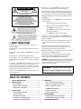
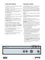
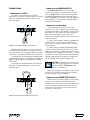
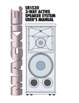
1
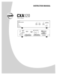
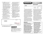
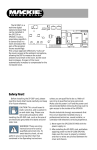
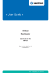
UP4000 Series
Power Amplifier
UP4061 • UP4121 • UP4161
Instruction Manual
UP 4161 - P.A. AMPLIFIER
STD-BY OVERLOAD SIGNAL
EQ
LOW
2
0
HIGH
2
2
4
4
8
8
6
0
4
2
4
4
8
8
6 6
-10
6
+10
-10
POWER INPUT
24V D.C.
-
D.C. FUSE
POWER OUTPUTS
0
50V
70V
0
100V
4
INPUT
25V
7
1
9
8
PRIORITY
VOLTAGE
SELECTOR
CAUTION
RISK OF ELECTRIC SHOCK
DO NOT OPEN
REPLACE WITH THE SAME TYPE FUSE AND RATING.
DISCONNECT SUPPLY CORD BEFORE CHANGING FUSE
LINE
50/60 Hz-115/230V
WARNING: TO REDUCE THE RISK OF FIRE OR ELECTRIC SHOCK, DO NOT
STAND GND OVERL. GND
BY
300mA.
max
GND
PARALLEL OUT
FILTER
SERIAL NUMBER
10
COMMANDS
BALANCED
IN
115
ON
POWER
6
2
+10
POWER OUTPUTS
5
3
0
+
PEAK
VOLUME
MANUFACTURING DATE
EXPOSE THIS EQUIPMENT TO RAIN OR MOISTURE. DO NOT REMOVE COVER.
NO USER SERVICEABLE PARTS INSIDE. REFER SERVICING TO QUALIFIED PERSONNEL.
AVIS: RISQUE DE CHOC ELECTRIQUE — NE PAS OUVRIR
UNBALANCED IN
UTILISE UN FUSIBLE DE RECHANGE DE MÊME TYPE.
DEBRANCHER AVANT DE REMPLACER LE FUSIBLE
CONCEIVED, DESIGNED, AND MANUFACTURED BY MACKIE INDUSTRIAL • MADE IN ITALY • PATENTS PENDING • COPYRIGHT ©1999
THE FOLLOWING ARE TRADEMARKS/REGISTERED TRADEMARKS OF MACKIE DESIGN INC.: "MACKIE", "MACKIE INDUSTRIAL", & THE "RUNNING MAN" FIGURE
SENSITIVITY
L.P.
H.P.
OFF
20dB
ON
0dB
CAUTION
AVIS
8. Power Sources — Connect the UP4000 to a power supply only of the type
described in these operation instructions or as marked on the rear panel.
RISK OF ELECTRIC SHOCK
DO NOT OPEN
RISQUE DE CHOC ELECTRIQUE
NE PAS OUVRIR
9. Power Cord Protection — Route power supply cords so that they are not likely to be
walked upon or pinched by items placed upon or against them, paying particular attention
to cords at plugs, convenience receptacles, and the point where they exit the UP4000.
CAUTION: TO REDUCE THE RISK OF ELECTRIC SHOCK
DO NOT REMOVE COVER (OR BACK)
NO USER-SERVICEABLE PARTS INSIDE
REFER SERVICING TO QUALIFIED PERSONNEL
10. Object and Liquid Entry — Do not drop objects into or spill liquids into the inside
of the UP4000.
ATTENTION: POUR EVITER LES RISQUES DE CHOC
ELECTRIQUE, NE PAS ENLEVER LE COUVERCLE. AUCUN
ENTRETIEN DE PIECES INTERIEURES PAR L'USAGER. CONFIER
L'ENTRETIEN AU PERSONNEL QUALIFIE.
AVIS: POUR EVITER LES RISQUES D'INCENDIE OU
D'ELECTROCUTION, N'EXPOSEZ PAS CET ARTICLE
A LA PLUIE OU A L'HUMIDITE
11. Damage Requiring Service — The UP4000 should be serviced only by qualified
service personnel when:
A. The power-supply cord or the plug has been damaged; or
B. Objects have fallen, or liquid has spilled into the UP4000; or
C. The UP4000 has been exposed to rain; or
The lightning flash with arrowhead symbol within an equilateral
triangle is intended to alert the user to the presence of uninsulated
"dangerous voltage" within the product's enclosure, that may be
of sufficient magnitude to constitute a risk of electric shock to persons.
Le symbole éclair avec point de flèche à l'intérieur d'un triangle
équilatéral est utilisé pour alerter l'utilisateur de la présence à
l'intérieur du coffret de "voltage dangereux" non isolé d'ampleur
suffisante pour constituer un risque d'éléctrocution.
The exclamation point within an equilateral triangle is intended to
alert the user of the presence of important operating and maintenance
(servicing) instructions in the literature accompanying the appliance.
Le point d'exclamation à l'intérieur d'un triangle équilatéral est
employé pour alerter les utilisateurs de la présence d'instructions
importantes pour le fonctionnement et l'entretien (service) dans le
livret d'instruction accompagnant l'appareil.
1. SAFETY INSTRUCTIONS
1. Read Instructions — Read all the safety and operation instructions before
operating the UP4000.
2. Retain Instructions — The safety and operating instructions should be kept for
future reference.
3. Heed Warnings — Follow all warnings on the UP4000 and in these operating
instructions.
4. Follow Instructions — Follow all operating and other instructions.
5. Water and Moisture — Do not use the UP4000 near water – for example, near a
bathtub, washbowl, kitchen sink, laundry tub, in a wet basement, near a swimming
pool, etc.
6. Ventilation — This UP4000 should be situated so that its location or position
does not interfere with its proper ventilation. For example, it should not be
situated on a bed, sofa, rug, or similar surface that may block any ventilation
openings, or placed in a built-in installation such as a bookcase or cabinet that
may impede the flow of air through ventilation openings.
7. Heat — Locate the UP4000 away from heat sources such as radiators, or other
devices which produce heat.
D. The UP4000 does not appear to operate normally or exhibits a
marked change in performance; or
E. The UP4000 has been dropped, or its chassis damaged.
12. Servicing — The user should not attempt to service the UP4000 beyond those
means described in this operating manual. All other servicing should be referred to the
Mackie Service Department.
13. To prevent electric shock, do not use this polarized plug with an extension cord,
receptacle or other outlet unless the blades can be fully inserted to prevent blade
exposure.
Pour prévenir les chocs électriques ne pas utiliser cette fiche polariseé avec un
prolongateur, un prise de courant ou une autre sortie de courant, sauf si les lames
peuvent être insérées à fond sans laisser aucune pariie à découvert.
14. Grounding or Polarization — Precautions should be taken so that the grounding or
polarization means of the UP4000 is not defeated.
15. This apparatus does not exceed the Class A/Class B (whichever is applicable)
limits for radio noise emissions from digital apparatus as set out in the radio
interference regulations of the Canadian Department of Communications.
ATTENTION —Le présent appareil numérique n’émet pas de bruits radioélectriques
dépassant las limites applicables aux appareils numériques de class A/de class B (selon
le cas) prescrites dans le règlement sur le brouillage radioélectrique édicté par les
ministere des communications du Canada.
WARNING — To reduce the risk of fire or electric
shock, do not expose this appliance to rain or moisture.
TABLE OF CONTENTS
1.
SAFETY INSTRUCTIONS ....................................... 2
2.
INTRODUCTION ..................................................... 3
USING THE BALANCED INPUT ......................... 9
KEY FEATURES ................................................... 3
USING THE UNBALANCED INPUT ................... 9
FRONT PANEL FEATURES ................................. 4
USING THE PARALLEL OUT .............................. 9
REAR PANEL FEATURES .................................... 4
COMMANDS STANDBY ..................................... 9
INSTALLATION ....................................................... 6
POWER OUTPUTS .............................................. 9
3.
4.
APPLICATION DIAGRAM ................................... 6
CONNECTIONS ................................................... 7
POWER INPUT 24V D.C. ..................................... 9
5.
SPECIFICATIONS .................................................. 10
INTERNAL SETTINGS ........................................ 8
UP4000 SERIES BLOCK DIAGRAM ................. 10
AC POWER CONSIDERATIONS ......................... 8
UP4000 SERIES SPECIFICATIONS ................... 10
THERMAL CONSIDERATIONS ........................... 8
UP4000 – 2
OPERATION ............................................................ 9
6.
SERVICE INFORMATION ..................................... 11
2. INTRODUCTION
The UP4000 Series Power Amplifiers are
designed for continuous duty in speech, music,
paging, and sound reinforcement applications in
churches, schools, offices, and other venues
demanding high performance, flexible features, and
rugged dependability.
Two discrete inputs with priority are provided.
The main program input is actively balanced and
terminated to a barrier strip connection on the rear
panel. The second input is unbalanced and terminated
to a single RCA connector. A contact closure will give
priority to the balanced input by muting the
unbalanced input. The unbalanced input features a
parallel output and 0 dB/20 dB sensitivity switch.
Output modes include 4Ω constant impedance
and 25V, 50V, 70V, and 100V constant voltage. The
smart output stage is fully protected against
permanent damage caused by overloading, shorts,
and extreme temperatures. Activation of the
overload protection circuit turns on 18 VDC (300mA)
power at a barrier connector on the rear panel, which
may be used to drive a relay or indicating LED. The
UP4000 Series will operate on either 115 VAC or
230 VAC, 50/60Hz, as determined by the Voltage
Selector switch, and supplied by a detachable IEC
power cord. Insulated terminals to connect a backup
24 VDC battery are provided on the rear panel.
Switchover to DC is automatic. A programmable
stand-by mode allows the amplifier to be turned on
remotely with a contact closure.
The front panel provides a Master volume control,
and Low and High EQ controls. The control knobs
can be removed for security, and their recessed
shafts covered with the supplied inserts. LEDs
indicate power, stand-by mode, signal present at
the output, peak, and output overload. 12 dB/octave
Low and High shelving equalization with up to 12 dB
of boost or cut at 100Hz and 10kHz can be applied
to the output signal.
Accessories include a rack mounting kit.
KEY FEATURES
•
Balanced and Unbalanced Inputs
•
Balanced Input Priority Function
•
Unbalanced Line-Level Output
•
Convection Cooled Power Amplifier
UP4061: 60 Watts RMS
UP4121: 120 Watts RMS
UP4161: 160 Watts RMS
•
4Ω Constant-Impedance Output
•
25V, 50V, 70V, and 100V Constant-Voltage Outputs
•
High-Pass and Low-Pass Filters
•
2 RU Rack-Mounting Kit
•
Automatic 24 VDC Backup Power Input
Part No. 910-142-30 Rev. A 10/01
© 2001 All Rights Reserved. Mackie Industrial. Printed in U.S.A.
UP4000 – 3
FRONT PANEL FEATURES
REAR PANEL FEATURES
LOW EQ is a shelving filter that provides 12 dB
of boost and cut below 100Hz.
POWER INPUT provides a means to connect an
external 24 VDC power supply or battery as an
alternative or backup power source. The UP4000
Series seamlessly switches to the backup supply if
there's an AC power loss. When both AC power
and 24 VDC power are connected, the DC power is
switched off.
HIGH EQ is a shelving filter that provides 12 dB
of boost and cut above 10kHz.
VOLUME is a master volume control used to
adjust the overall volume of the signal at the
POWER OUTPUTS.
Note: The unit is not equipped with battery charging
capability.
Use the POWER switch to turn the UP4000
Series on and off.
The D.C. FUSE protects the DC power input to
the amplifier circuit. Replace with the same type
fuse only.
The STD-BY indicator lights when the amplifier is
in standby mode.
Note: Standby mode is disabled by default. An
internal jumper (J1 on the input board) must be
changed to enable standby mode. See "Internal
Settings" on page 8.
POWER OUTPUTS are screw-terminal
connections for connecting speakers to the 4-ohm,
25V, 50V, 70V, or 100V outputs.
WARNING: To prevent the risk of electric shock,
never touch the bare wires coming from the output
terminals of the amplifier when it is switched on.
When all connections have been made, insulate the
output terminals of the amplifier using the
protective cover provided.
The OVERLOAD indicator lights when the
amplifier is operating in overload, a condition
generally caused by a problem on the speaker line.
When the amplifier is switched on, the OVERLOAD
light comes on for a few seconds. This is normal
and does not indicate a problem.
Constant-Impedance Output
The total impedance of the speakers and cable
connected to the "4Ω" constant-impedance output
should be 4 ohms. Connect the "4Ω" terminal to
the "+" (HIGH) speaker terminal, and the "0"
terminal to the "–" (LOW) speaker terminal.
Constant-Voltage Output
In a constant-voltage system, each speaker must
be equipped with a line transformer having an
input voltage equal to that of the line (e.g., 25V,
50V, 70V, or 100V). Typically, these line transformers have selectable power taps (i.e., 2.5W,
5W, 10W) for connecting to the constant-voltage
line. CAUTION: The sum of the wattage values
of the speakers must not exceed the output
power of the amplifier.
The SIGNAL indicator lights when a signal is
present at the POWER OUTPUTS.
The PEAK indicator lights when the output signal
is approaching clipping.
The ON indicator lights when the UP4000 is
turned on and ready for operation.
UP 4161 - P.A. AMPLIFIER
STD-BY OVERLOAD SIGNAL
EQ
LOW
2
0
HIGH
2
2
4
0
4
2
4
4
4
6 6
6
8
8
-10
+10
6
8
8
-10
+10
5
ON
POWER
6
3
7
1
9
2
8
0
UP4000 – 4
PEAK
VOLUME
10
The OVERL. 300mA terminal is active whenever
the amplifier's overload protection circuit is
activated. This provides 18 VDC with a maximum
output capacity of 300mA for driving an auxiliary
relay or indicating LED.
Connect the appropriate POWER OUTPUT
voltage terminal to the "+" (HIGH) leg and the "0"
terminal to the "–" (LOW) leg of the distributed
speaker system.
The ground ( ) terminal is internally connected
to the chassis and safety ground on the AC linecord.
The OVERL. GND terminal on the COMMANDS
terminal strip is the common connection point for
OVERL. 300mA.
The PRIORITY terminal activates the priority
function for the BALANCED IN by using an external
normally-open switch to short-circuit the PRIORITY
terminal to the GND
(ground) terminal. When the
PRIORITY function is enabled, the UNBALANCED IN
is muted (no signal from the UNBALANCED IN is
transmitted to the outputs).
AC Protection Fuse protects the power supply
and amplifier circuitry. Replace only with same type
fuse.
Connect the supplied AC linecord to the IEC AC
Socket. The AC line fuse is contained in the socket,
behind the cover located at the bottom of the
socket. Replace only with same type fuse.
This GND terminal is the common connection
point for BALANCED IN and PRIORITY.
The BALANCED IN terminals are the main input
for the amplifier and accept a balanced line-level
signal (0 dBu nominal). This input has a priority
function, which mutes the UNBALANCED IN signal
when the PRIORITY terminal is shorted to GND.
The VOLTAGE SELECTOR switch is used to
select the AC supply voltage for the amplifier. Move
the switch so the AC line voltage used appears on
the switch (DOWN for 115V, UP for 230V).
The STAND BY terminal is used to turn on the
amplifier with a remote switch.
The H.P. switch activates a high-pass filter on the
balanced and unbalanced inputs, which attenuates
frequencies below 300Hz at 12 dB/octave.
Note: Standby mode must first be activated by
moving a jumper (J1) on the input board (standby
mode is disabled by default). See "Internal Settings"
on page 8.
The L.P. switch activates a low-pass filter on the
balanced and unbalanced inputs, which attenuates
frequencies above 7kHz at 12 dB/octave.
UNBALANCED IN is an RCA jack that can be
used instead of the BALANCED IN, or both can be
used with the PRIORITY function, which gives the
BALANCED IN priority over the UNBALANCED IN.
When the POWER switch is turned on, the amplifier
goes into standby mode. In this state, the amplifier
is on but signal is not allowed to pass. Shorting the
STAND BY terminal to the GND
terminal with an
external switch causes the amplifier to become fully
operational.
PARALLEL OUT is an RCA jack that is in parallel
with the UNBALANCED IN jack for connecting to
the input of another power amplifier.
The STANDBY GND terminal on the
COMMANDS terminal strip is the common
connection point for STAND BY.
+
POWER INPUT
24V D.C.
-
D.C. FUSE
The SENSITIVITY switch adjusts the input
sensitivity of the UNBALANCED IN from 0 dB
(typical line-level signals) to 20 dB (for low-level
signals).
POWER OUTPUTS
0
50V
70V
POWER OUTPUTS
0
100V
4
INPUT
25V
PRIORITY
COMMANDS
STAND GND OVERL. GND
BY
300mA.
max
GND
BALANCED
IN
115
VOLTAGE
SELECTOR
CAUTION
RISK OF ELECTRIC SHOCK
DO NOT OPEN
REPLACE WITH THE SAME TYPE FUSE AND RATING.
DISCONNECT SUPPLY CORD BEFORE CHANGING FUSE
LINE
50/60 Hz-115/230V
WARNING: TO REDUCE THE RISK OF FIRE OR ELECTRIC SHOCK, DO NOT
PARALLEL OUT
FILTER
SERIAL NUMBER
MANUFACTURING DATE
EXPOSE THIS EQUIPMENT TO RAIN OR MOISTURE. DO NOT REMOVE COVER.
NO USER SERVICEABLE PARTS INSIDE. REFER SERVICING TO QUALIFIED PERSONNEL.
AVIS: RISQUE DE CHOC ELECTRIQUE — NE PAS OUVRIR
UNBALANCED IN
UTILISE UN FUSIBLE DE RECHANGE DE MÊME TYPE.
DEBRANCHER AVANT DE REMPLACER LE FUSIBLE
CONCEIVED, DESIGNED, AND MANUFACTURED BY MACKIE INDUSTRIAL • MADE IN ITALY • PATENTS PENDING • COPYRIGHT ©1999
THE FOLLOWING ARE TRADEMARKS/REGISTERED TRADEMARKS OF MACKIE DESIGN INC.: "MACKIE", "MACKIE INDUSTRIAL", & THE "RUNNING MAN" FIGURE
SENSITIVITY
L.P.
H.P.
OFF
20dB
ON
0dB
UP4000 – 5
Jukebox
3. Installation
Application Diagram
Paging Mic
70V Loudspeakers
Paging Mic/Jukebox
Priority Switch
AM/FM Tuner
Mixer
Line
Out
Cassette or DAT Recorder
CD Player
Mono
Preamplifier
–
+
+
POWER INPUT
24V D.C.
-
D.C. FUSE
24 VDC
Backup
Power Supply
POWER OUTPUTS
0
50V
70V
POWER OUTPUTS
0
100V
4
INPUT
25V
PRIORITY
COMMANDS
STAND GND OVERL. GND
BY
300mA.
max
GND
BALANCED
IN
115
VOLTAGE
SELECTOR
CAUTION
WARNING: TO REDUCE THE RISK OF FIRE OR ELECTRIC SHOCK, DO NOT
MANUFACTURING DATE
UNBALANCED IN
UTILISE UN FUSIBLE DE RECHANGE DE MÊME TYPE.
DEBRANCHER AVANT DE REMPLACER LE FUSIBLE
CONCEIVED, DESIGNED, AND MANUFACTURED BY MACKIE INDUSTRIAL • MADE IN ITALY • PATENTS PENDING • COPYRIGHT ©1999
THE FOLLOWING ARE TRADEMARKS/REGISTERED TRADEMARKS OF MACKIE DESIGN INC.: "MACKIE", "MACKIE INDUSTRIAL", & THE "RUNNING MAN" FIGURE
LINE
50/60 Hz-115/230V
SENSITIVITY
L.P.
H.P.
AVIS: RISQUE DE CHOC ELECTRIQUE — NE PAS OUVRIR
REPLACE WITH THE SAME TYPE FUSE AND RATING.
DISCONNECT SUPPLY CORD BEFORE CHANGING FUSE
–
SERIAL NUMBER
EXPOSE THIS EQUIPMENT TO RAIN OR MOISTURE. DO NOT REMOVE COVER.
NO USER SERVICEABLE PARTS INSIDE. REFER SERVICING TO QUALIFIED PERSONNEL.
RISK OF ELECTRIC SHOCK
DO NOT OPEN
PARALLEL OUT
FILTER
OFF
20dB
ON
0dB
+
+
POWER INPUT
24V D.C.
-
D.C. FUSE
24 VDC
Backup
Power Supply
POWER OUTPUTS
0
50V
70V
POWER OUTPUTS
0
100V
4
INPUT
25V
PRIORITY
COMMANDS
STAND GND OVERL. GND
BY
300mA.
max
GND
BALANCED
IN
115
VOLTAGE
SELECTOR
CAUTION
WARNING: TO REDUCE THE RISK OF FIRE OR ELECTRIC SHOCK, DO NOT
MANUFACTURING DATE
UNBALANCED IN
UTILISE UN FUSIBLE DE RECHANGE DE MÊME TYPE.
DEBRANCHER AVANT DE REMPLACER LE FUSIBLE
CONCEIVED, DESIGNED, AND MANUFACTURED BY MACKIE INDUSTRIAL • MADE IN ITALY • PATENTS PENDING • COPYRIGHT ©1999
THE FOLLOWING ARE TRADEMARKS/REGISTERED TRADEMARKS OF MACKIE DESIGN INC.: "MACKIE", "MACKIE INDUSTRIAL", & THE "RUNNING MAN" FIGURE
LINE
50/60 Hz-115/230V
SENSITIVITY
L.P.
H.P.
AVIS: RISQUE DE CHOC ELECTRIQUE — NE PAS OUVRIR
REPLACE WITH THE SAME TYPE FUSE AND RATING.
DISCONNECT SUPPLY CORD BEFORE CHANGING FUSE
PARALLEL OUT
FILTER
SERIAL NUMBER
EXPOSE THIS EQUIPMENT TO RAIN OR MOISTURE. DO NOT REMOVE COVER.
NO USER SERVICEABLE PARTS INSIDE. REFER SERVICING TO QUALIFIED PERSONNEL.
RISK OF ELECTRIC SHOCK
DO NOT OPEN
OFF
20dB
ON
0dB
COMMANDS
COMMANDS
Loudspeaker
(8Ω)
Loudspeaker
(8Ω)
STAND GND OVERL. GND
BY
300mA.
max
STAND GND OVERL. GND
BY
300mA.
max
RESISTOR
1KΩ
1/2W
–
LED
+
RELAY
Note: This illustration demonstrates a typical application using a pair of UP4000 Series Power
Amplifiers. A paging microphone and a jukebox are connected to the Balanced Input of Amp 1 via the
Mixer, and the Input priority function can be switch-activated to give the paging mic and jukebox priority
over the signal source connected to the Unbalanced Input. A preamplifier is connected to the Unbalanced
Input, with source selections for an AM/FM Tuner, Cassette or DAT Recorder, and CD Player. The Parallel
Out is connected to the Unbalanced Input on a second UP4000 Series. 70V constant-voltage speakers
are connected to the 70V tap on Amp 1, and a pair of 8-ohm speakers (connected in parallel for a total
impedance of 4 ohms) are connected to the 4Ω tap on Amp 2.
UP4000 – 6
Connections
Connecting the UNBALANCED IN
Connecting the INPUT
The Input has a balanced screw terminal
connector that accepts a line-level signal. The screw
terminals should be connected as shown in the
following figure:
–
+
PRIORITY
GND
HOT (+)
SHIELD
COLD (–)
BALANCED
IN
INPUT Terminal Strip: Balanced Connection
Strip the wire back about 1/2" inch, loosen the
screw enough to loop the wire around the shaft of
the screw (clockwise), and tighten down the screw
with either a slot-head or phillips-head screwdriver.
Use high-quality, three-conductor shielded cable
for balanced connections. The better the shield, the
better the audio signal is protected from induced
EMI and RFI.
If connecting an unbalanced line-level signal to
the Input, wire the connections as shown in the
following figure:
JUMPER
–
+
The UNBALANCED IN uses an RCA-type
connector. It accepts a line-level signal (–10 dBV)
with the SENSITIVITY switch in the 0 dB position
(pushed IN). When connecting a low-level signal,
push the SENSITIVITY switch OUT (20 dB position).
Use high-quality, two-conductor shielded cable to
make these connections.
Connecting the Speakers
The speaker output connectors are screw
terminals. Use 16 or 18 gauge wire for connecting
the amplifier outputs to the speakers. Strip the wire
back about 1/2" inch, loosen the screw enough to
loop the wire around the shaft of the screw
(clockwise), and tighten down the screw with a slothead screwdriver.
If using a 4-ohm speaker, connect the 4Ω output
terminal to the "+" terminal on the speaker, and
connect the "0" output terminal to the "–" terminal
on the speaker.
If using a constant-voltage distributed speaker
system, connect either the 25V, 50V, 70V, or 100V
output terminal to the "+" side of the speaker system,
and connect the "0" output terminal to the "–" side of
the speaker system. Make sure that the taps on the
speakers add up to no more than the rated power
for the UP4000 Series Amplifier being used.
CAUTION: To prevent the risk of electric
shock, never touch the bare wires coming
from the OUTPUT TERMINALS of the
amplifier when it is switched on.
When the connections have been made, insulate
the 50V, 70V, and 100V terminals of the amplifier
using the protective cover supplied.
Connecting the POWER INPUT 24V.D.C.
PRIORITY
GND
HOT (+)
SHIELD
BALANCED
IN
Connect a 24 VDC power supply to these spring
terminals as an alternate method to power the
UP4000 Series. To minimize the voltage drop across
the wire and prevent overheating, use at least 16
AWG wire for the UP4061, and 14 AWG wire for
the UP4121 and UP4161.
INPUT Terminal Strip: Unbalanced Connection
UP4000 – 7
Internal Settings
Thermal Considerations
There is one setting that can be changed inside
the UP4000 Series Amplifier. This setting should be
made prior to installation.
IMPORTANT: The UP4000 Series amplifier is
convection cooled rather than fan cooled. Heat is
drawn away from the amplifier by the heatsink and
radiated through the cooling vents in the top cover.
When installing the UP4000 Series, be sure to
allow sufficient air space around the top and rear of
the amplifier to allow adequate cooling for the
heatsink. Leave at least one rack space above and
below the UP4000 and at least 6 inches behind the
chassis to allow proper ventilation.
CAUTION: These servicing instructions
are for use by qualified personnel only. To
avoid electric shock, do not perform any
servicing other than that contained in the Operating
Instructions unless you are qualified to do so.
Refer all servicing to qualified service personnel.
Make sure the power is off and the power cord
disconnected before removing the top cover to gain
access to the inside of the UP4000 Series.
STANDBY MODE
Jumper J1 on the input board allows you to
enable the Standby function. Standby mode is
disabled by default. You must change jumper J1 on
the input board to enable the Standby function.
UP4000 SERIES
INPUT BOARD
If the amplifier should overheat, a thermal
switch is activated that turns off the power
amplifier, allowing the heatsinks to cool down. The
ON indicator on the front panel will remain lit. Once
the amplifier has cooled to a safe operating
temperature, the thermal switch resets and
reactivates the amplifier. If this should occur,
identify the cause of the problem and take
corrective action (i.e.,
provide better
ventilation, install a fan
in the rack, make sure
the amplifier is not
overloaded by too low
JP6
J1
of a load impedance or
STANDBY ENABLED
by a short circuit on the
STANDBY DISABLED
(DEFAULT)
speaker line).
3
2
1
UP4000 Series Input Board Jumper
AC Power Considerations
The UP4000 Series draw an average AC line
current as indicated on the following chart:
UP4060
UP4120
UP4160
115VAC
230VAC
1.5A
4.0A
4.8A
0.8A
2.0A
2.4A
Voltage Conversion
The UP4000 Series can be configured to operate
at 115 VAC or 230 VAC. Be sure the VOLTAGE
SELECTOR switch on the rear panel is set to the
correct position for the AC power supply being used.
115
UP4000 – 8
VOLTAGE
SELECTOR
230
VOLTAGE
SELECTOR
COMMANDS STANDBY
4. Operation
Using the BALANCED IN
The BALANCED IN accepts a line-level signal.
Connect the input source to the BALANCED IN
barrier strip screw terminals.
PRIORITY Function
The BALANCED IN has priority over the
UNBALANCED IN. The priority function can be
activated by connecting a normally-open switch
between the input PRIORITY terminal and the GND
terminal on the INPUT barrier strip on the rear
panel. Closing the switch activates the priority
function and mutes the UNBALANCED IN.
Using the UNBALANCED IN
The UNBALANCED IN accepts either a line-level
signal (0 dB position) or a low-level signal (20 dB
position), using the input SENSITIVITY switch.
High-Pass Filter
Push in the H.P. switch to engage the high-pass
filter, which rolls off frequencies below 300Hz at
12 dB/octave.
An external normally-open switch can be
connected between the STANDBY terminal and the
GND terminal on the COMMANDS barrier strip on the
rear panel. Closing the switch enables the signal to
pass through the amplifier, and opening the switch puts
the amplifier in standby mode (power on, no signal).
Note: The UP4000 Series is shipped with the
Standby Mode disabled. Move jumper J1 on the
input board to enable the Standby Mode (see
instructions on page 8).
OVERL.
Connect an LED or relay between this terminal
and the GND terminal to provide an external
indication if the overload circuit has been activated.
It provides +18 VDC with a maximum output
capacity of 300mA when activated. See "Application
Diagram" on page 6.
POWER OUTPUTs
The amplifier outputs on the UP4000 Series can
be used with a 4-ohm impedance load, or to directly
drive a 25V, 50V, 70V, or 100V distributed system
(constant-voltage system).
Low-Pass Filter
Push in the L.P. switch to engage the low-pass
filter, which rolls off frequencies above 7kHz at
12 dB/octave.
Note: The H.P. and L.P. filters affect both the
balanced and unbalanced inputs.
Direct Speaker Connection
If the UP4000 Series is not being used in a
distributed speaker system, you can connect a
speaker with a 4-ohm load between the "4Ω"
terminal and the "0" terminal.
Distributed Speaker System
Using the PARALLEL OUT
The PARALLEL OUT connector is provided to
connect the UNBALANCED IN signal to multiple
amplifiers in a daisy-chain configuration.
To Next
Amplifier
When using the UP4000 Series in a distributed
system, connect the distributed system between
the appropriate POWER OUTPUT terminal (25V, 50V,
70V, or 100V) and the "0" terminal. Make sure the
speakers in the system are tapped appropriately so
they do not exceed the rated power of the amplifier.
(AM4060 = 60 watts, AM4120 = 120 watts,
AM4160 = 160 watts).
POWER INPUT 24V D.C.
From Signal
Source
UP4000 Series Daisy-Chaining Inputs
The UP4000 Series can be powered using a 24
VDC power supply. This can serve as the primary
power supply for the UP4000 Series, or as a
backup supply in case of an AC power failure. The
UP4000 Series seamlessly switches to the backup
supply if there is a power loss. When both AC power
and 24 VDC power are connected, the AC power is
used and no current is drawn from the DC supply.
Note: The unit is not equipped with battery
charging capability.
UP4000 – 9
5. Specifications
UP4000 Series Block Diagram
SENSITIVITY
MASTER
VOLUME
0 dB
20 dB
UNBALANCED IN
PARALLEL OUT
INPUT
PRIORITY
MUTE
INPUT
HP
LP
LO
HI
300
7K
100
10K
STANDBY
MUTE
PRIORITY
BALANCED IN
GND
STD-BY
COMMANDS
STANDBY
GND
OVERL.
GND
+18VDC
OVERLOAD
SIGNAL
100V
70V
50V
25V
4Ω
0
POWER
AMPLIFIER
MACKIE INDUSTRIAL
UP4000 SERIES
BLOCK DIAGRAM
(#2.02.01.DF)
PEAK
AUDIO
OUTPUT
TRANSFORMER
FEEDBACK LOOP
UP4000 Series Specifications
Power Amplifier Section
Input Sensitivity
Continuous Sine Wave Average Output Power, both channels
driven:
Balanced Line Input:
775mV
Unbalanced Line Input:
0 dB:
775mV
20 dB:
80mV
UP4061:
UP4121:
UP4161:
60 watts RMS nominal; 90 watts peak (10ms)
120 watts RMS nominal; 180 watts peak (10ms)
160 watts RMS nominal; 220 watts peak (10ms)
Frequency Response
50Hz to 15kHz (±3 dB)
Distortion
THD: < 1% @ 1kHz nominal power
EQ
HP Filter:
LP Filter:
300Hz @ 12 dB/octave
7kHz @ 12 dB/octave
2-Band Output EQ:
High Shelving:
Low Shelving:
±12 dB @ 10kHz
±12 dB @ 100Hz
Signal-To-Noise Ratio
Audio Outputs
> 80 dB below nominal power
Audio Inputs
Balanced Line Input:
One active balanced barrier strip
Unbalanced Line Input: One unbalanced RCA connector with
Sensitivity switch
Input Impedance
Balanced Line Input:
100kΩ
Unbalanced Line Input:
0 dB:
50kΩ
20 dB:
50kΩ
UP4000 – 10
Low Impedance:
Constant Voltage:
Unbalanced Out:
4Ω
25V, 50V, 70V, 100V
One unbalanced RCA connector,
parallel to Unbalanced In
Control Inputs and Outputs
Inputs:
Outputs:
Priority switch, dry contact closure
Standby switch, dry contact closure
Overload Indicator, 18 VDC @ 300mA
General
6. Service Information
Power Consumption
UP4060:
UP4120:
UP4160:
180 VA
450 VA
550 VA
In the event that your UP4000 Series amplifier
should require servicing, please follow these
instructions:
AC Line Voltage
115 VAC, 60Hz
230 VAC, 50Hz
Fuse Ratings
Model
Line Fuse 230 VAC
UP4060
UP4120
UP4160
1.25AT
2.5AT
3.15AT
Line Fuse 115 VAC
2.5AT
5AT
6.3AT
24 VDC Fuse
5AT
10AT
16AT
1. Call Mackie Industrial Tech Support at 1-888-3377404, 8 am to 5 pm PST (Monday-Friday), to verify
the problem and obtain a Return Authorization (RA)
Number. Be sure to have the serial number of the
unit when you call. You must have a Return
Authorization Number in order to obtain warranty
service at the factory or at an authorized service
center.
Dimensions
Height:
Width:
Depth:
Weight:
3.5" (88mm)
17.0" (431mm)
12.4" (314mm)
UP4061: 22 lbs. (10.0kg)
UP4121: 28 lbs. (12.7kg)
UP4161: 31 lbs. (14.1kg)
2. Pack the unit in its original packaging. This is very
important. Mackie Industrial is not responsible for
any damage that occurs during shipping due to
non-conventional packaging. Original packaging
helps to minimize the possibility of shipping
damage.
3. Include a legible note stating your name, return
shipping address, (no P.O. boxes), daytime phone
number, Return Authorization Number, and a
detailed description of the problem, including how
we can duplicate it.
4. Write the Return Authorization Number in BIG
BOLD PRINT on the top of the box.
5. Ship the unit to us. We suggest insurance for all
forms of cartage. Ship to this address:
Mackie Industrial
Service Department
One Main Street
Whitinsville, MA 01588
Disclaimer
Mackie Industrial continually engages in
research related to product improvement, new
materials, and production methods. Design
refinements are introduced into existing products
without notice as a routine expression of that
philosophy. For this reason, any current Mackie
Industrial product may differ in some respect from
its published description, but will always equal or
exceed the original design specifications unless
otherwise stated.
Mackie Industrial is a trademark of Mackie
Designs Inc.
All other brand names mentioned are
trademarks or registered trademarks of their
respective holders, and are hereby acknowledged.
© 2001 All Rights Reserved.
Mackie Industrial.
Printed in the U.S.A.
UP4000 – 11
UP4000 Series
Power Amplifier
www.mackieindustrial.com
16220 Wood-Red Road NE, Woodinville, WA 98072 USA
TEL 888.337.7404, FAX 425.487.4337, [email protected]
UK +44.1268.571.212, FAX +44.1268.570.809 [email protected]
ITALY +39.0522.354.111, FAX +39.0522.926.208 [email protected]
FRANCE +33.3.8546.9160, FAX +33.3.8546.9161 [email protected]
GERMANY +49.2572.96042.0, FAX +49.2572.96042.10 [email protected]