1
WLS Series
Operating Instructions and Parts Manual
Please read and save these instructions. Read carefully before attempting to assemble, install, operate or maintain the product described.
Protect yourself and others by observing all safety information. Failure to comply with instructions could result in personal injury and/or property damage! Retain instructions for future reference.
Lawn
Sprinkler
Pump
This pump is nonsubmersible.
Description
This pump is a high capacity, self-priming centrifugal pump suitable for lawn
sprinkling or other applications where
large quantities of water are required.
Flammable liquids such as gasoline,
chemicals or corrosive liquids should
never be used with this pump.
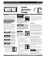
Safety Guidelines
Pump only clear water. Do
not pump flammable or
explosive fluids such as
gasoline, fuel oil,
kerosene, etc. Do not use in a flammable and/or explosive atmosphere.
Personal injury and/or property damage could result.
This manual contains information that
is very important to know and understand. This information is provided for
SAFETY and to PREVENT EQUIPMENT
PROBLEMS. To help recognize this
information, observe the following
symbols.
This pump is not
designed to handle
salt water, brine, laundry discharge or
any other application which may contain caustic chemicals and/or foreign
materials. Pump damage could occur if
used in these applications and will
void warranty.
Danger indicates
an imminently hazardous situation which, if not avoided,
will result in death or serious injury.
Warning indicates
a potentially hazardous situation which, if not avoided,
could result in death or serious injury.
Caution indicates a
potentially hazardous situation which, if not avoided,
may result in minor or moderate injury.
Notice indicates
important information, that if not followed, may cause
damage to equipment.
!
NOTICE
General Safety Information
1. Read these rules and
instructions carefully.
Failure to follow these
MANUAL
instuctions could
cause serious bodily
injury and/or property damage.
!
NOTICE
All wiring must be performed by a qualified
electrician. The pump
must be installed in compliance with all local and national
codes.
2. Connect this product to a grounded
circuit equipped with a ground
fault interruptor device.
3. Before installing this product, have
the electrical circuit checked by an
electrican to ensure proper grounding.
4. BE CERTAIN the pump
power source is disconnected before
installing or servicing
pump.
5. Check motor voltage setting on
motor endplate and make sure the
line voltage of the electrical current
supply is correct.
6. Be sure the water source and piping
is clear of sand, dirt and scale.
© 1998 Wayne Home Equipment
Debris will clog pump and void warranty.
7. Failure to protect pump and piping
from freezing could cause severe
damage and will void the warranty.
8. Do not run pump dry. Follow priming instructions.
Installation
Protect pump from the elements by
installing in a basement, garage, tool
shed or pump house. Install the pump so
the centerline of the pump is as close as
possible to the water level. Keep installation area clear to provide access for service and maintenance. Protect the pump
against flooding and excess moisture.
Make sure the pump has adequate ventilation. The surrounding temperature
should not exceed 100oF (38oC) or nuisance tripping of the motor may occur.
PUMP PIPING INSTALLATION
Use new pipe for best results.
Galvanized or plastic pipe can be used.
When using galvanized pipe, provide
independent supports for both suction
and discharge piping near the pump to
avoid strain on the pump. Minimize use
of elbows and fittings to reduce friction
loss. Refer to the friction loss chart for
specific information.
Increase diameter of suction or discharge piping if length is over 50 feet.
SUCTION PIPING
Install foot valve
or strainer screen
over intake of suction piping.
Never use pipe smaller than 2” in
diameter for suction piping. The suction pipe must be kept free of air leaks.
320200-001 6/98
Operating Instructions and Parts Manual
Lawn Sprinkler Pump
Installation (Continued)
To Pump
To Pump
For horizontal runs, lay pipe from the
water source so the upward slope is at
least 1/2” per foot. This eliminates
trapped air. The threaded inlet of the
pump is 2” NPT.
Well Seal
Do not install suction piping near
swimming areas.
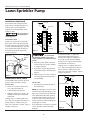
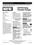
DISCHARGE PIPING
Install a 1-1/2” pipe tee in the pump
discharge to allow easy priming. Plug
the end of the tee opposite the pump
to allow the branch piping to go to the
spray nozzles (See Figure 1). Remove
the pipe plug to fill the pump with
water for priming.
Pipe Plug
To Spray
Nozzles
1-1/2” Pipe
Tee
Short
Section
of Pipe
Pump
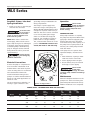
Foot Valve
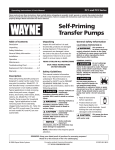
Drive Point
Well
Casing
Figure 2
Figure 3
Locate foot valve
no closer than 2
feet from the bottom of the well so
sand or sediment is not drawn into the
system.
4. After the proper depth is reached,
install a well seal or pitless adapter
to support the pipe.
5. Slope the horizontal pipe upward
toward the pump to eliminate trapping air.
CONNECTION TO WATER SOURCE
6. When using a foot valve, a priming
tee and plug above the well seal is
recommended.
The maximum vertical suction lift from
pump to the water level is 25 feet.
DRIVEN WELL
Figure 1
DRILLED WELL
1. Install a foot valve on the first section of pipe (see Figure 2).
2. Lower the pipe into the well.
3. Add pipe until the foot valve is 10
feet below the lowest anticipated
water level.
Leaking joints or couplings will allow
air to leak into the pipe and cause poor
pump operation. Make sure to use
pipe joint compound or Teflon® tape on
all pipe connections.
Packer Type
Foot Valve
1. Drive the point several feet below
the water table.
NOTE: A packer-type foot valve can be
installed in the well (See Figure 3). This
type of foot valve allows the well pipe
to be filled with water when priming
and makes the inlet pipe much easier
to test for leaks. Follow the manufacturer’s instructions when installing the
packer-type foot valve.
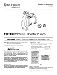
As an alternative, an in-line check valve
can be used with a driven well (See
Figure 4).
2
It may be necessary to supply the
pump with multiple well points to
maintain the high flow capability of
this pump. Consult with a plumbing
professional for appropriate materials
and installation instructions.
Leaking joints or couplings will allow
air to leak into the pipe and cause poor
pump operation. Make sure to use
pipe joint compound or Teflon® tape on
all pipe connections.
To Pump
Inline Check Valve
Drive Point
Figure 4
Operating Instructions and Parts Manual
WLS Series
Dug Well, Cistern, Lake And
Spring Installation
grounding screw provided within the
wiring compartment.
1. Install a foot valve on the inlet pipe
and lower into the water.
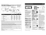
The voltage of power supply must
match the voltage of the pump. The
WLS75, WLS100 and WLS150 have dual
voltage motors preset at the factory to
230 volts. The motors can be converted
to 115 volts by turning the voltage
selector to the desired voltage (See
Figure 5). Use a needle nose pliers to
pull the selector out approximately
1/4”, rotate and then reinsert in correct
position. The WLS200 cannot be converted; the motor is 230 volts only.
Locate foot valve
no closer than 2
feet from the bottom of the water
source so sand or sediment is not
drawn into the system.
NOTE: When a lake is used for the
water supply, make sure the suction
pipe is deep enough to be submerged
at all times. Slope the pipe upward
toward the pump to eliminate trapping air. The pipe must be removed
during winter months or protected
against freezing.
Operation
Never run the
pump dry. Running
pump without water may cause seal
damage. Fill the pump with water
before starting.
PRIMING THE PUMP
After pump installation is complete,
the pump must be primed. Remove the
pipe plug in the discharge piping and
fill the pump and suction pipe with
clean water. Turn power to pump on. If
the pump does not pump water in 10
minutes, turn off the pump and refill
with clean water.
If the pump does not operate after
repeated attempts, check the following:
Protect the pipe
from damage by
swimmers and boaters.
1. Vertical distance of pump to water
level must not be over 25 feet.
230 V
2. Suction piping must be air tight.
Electrical Connections
115 V
3. Be sure valve(s) are open if used in
discharge or suction piping.
Connect the pump to a separate electrical circuit with a dedicated circuit
breaker. Refer to the electrical specifications in wiring chart for recommended circuit breaker and wire size.
Never run the
pump with a
closed or clogged discharge. The water
inside the pump could boil and damage
the pump.
Install and maintain wiring for this
pump in accordance with the National
Electrical code and all applicable local
electrical codes.
The motor must be grounded by connecting a copper conductor to the
230 V
Maintenance
Maintain adequate ventilation for the
pump motor. The motor bearings are
permanently lubricated at the factory.
Additional lubrication is not required.
115 V
Figure 5 - Voltage Selector
WIRING CHART - RECOMMENDED WIRE AND FUSE SIZES
Fuse
Rating
Amps
Distance in Feet From Motor to Supply
0
51
101
201
50
100
200
300
(AWG Wire Size)
Model
HP
Volts
Max.
Load
Amps
WLS75
3/4
115
230
13.5
7.0
20
15
12
14
12
14
10
12
10
12
WLS100
1
115
230
14.8
7.4
20
15
12
14
12
14
10
12
10
12
WLS150
1-1/2
115
230
17.0
8.5
30
15
10
14
10
14
8
12
8
12
WLS200
2
230
12.0
15
14
14
12
12
3
Operating Instructions and Parts Manual
Lawn Sprinkler Pump
Maintenance (Continued)
DRAINING FOR WINTER
Always protect pump and piping
against freezing temperatures. If there
is any danger of freezing, drain the system. To drain the system:
2. Remove the 1/4” plug from the
lower front face of the pump.
3. Drain all piping below the frost line.
1. Remove the pipe plug from the discharge tee.
Lift
in Feet
3/4 HP Pump Capacity in GPH
Operating Pressure (psi)
10
20
30
Lift
in Feet
1 HP Pump Capacity in GPH
Operating Pressure (psi)
10
20
30
5
3900
3320
2320
5
4410
3920
2570
10
3780
3120
2100
10
4180
3520
2300
15
3600
2910
1190
15
3830
3340
1780
20
3250
2670
990
20
3680
3060
1160
25
3010
2560
840
25
3340
2720
1260
Lift
in Feet
1-1/2 HP Pump Capacity in GPH
Operating Pressure (psi)
10
20
30
40
Lift
in Feet
2 HP Pump Capacity in GPH
Operating Pressure (psi)
10
20
30
40
5
4790
4480
3480
2060
5
5980
5560
4310
3060
10
4610
4310
3190
1520
10
5410
5220
4090
2880
15
4320
4040
2900
0
15
5230
4980
3900
2570
20
3900
3720
2680
0
20
4120
3840
3510
2210
25
3810
3300
2390
0
25
3980
3600
3300
0
Pipe
Size
1200
1500
psi Friction Loss in 100 Feet of Plastic Pipe*
(Gallons per Hour)
1800
2400
3000
3600
1-1/4
2.6
3.9
5.5
9.4
14.1
1-1/2
1.2
1.9
2.6
4.4
6.7
9.4
15.9
0.6
0.8
1.3
2.0
2.8
0.6
0.8
1.2
2
2-1/2
* Multiply by 1.8 for steel pipe
4
4800
6000
7200
4.7
7.1
10.0
1.3
3.0
4.2
Operating Instructions and Parts Manual
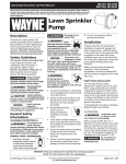
For Replacement Parts, call 1-800-237-0987
1
3
Please provide following information:
- Model number
- Serial number (if any)
- Part description and number as
shown in parts list
Address parts correspondence to:
Wayne Home Equipment
100 Production Drive
Harrison, OH 45030 U.S.A.
7
4
2
9
11
5
10
6
8
Ref.
No. Description
Part Number for Models:
WLS75
WLS100
WLS150
WLS200
1
2
3
4
5
6
7
8
9
10
11
32031-001
16334
41011-001
15559-002
29806-001
29807-001
67017-001
19013-001
41010-001
67018
16314-002
32020-001
16334
41011-001
15559-002
29804-001
29807-001
67017-001
19013-001
41010-001
67018
16314-002
32021-001
16334
41011-001
15559-002
29803-001
29807-001
67017-001
19013-001
41010-001
67018
16314-002
Motor
3/8”-16 x 1” Hex cap screw
Sealplate
Shaft seal assembly
Impeller
Diffuser
10-24 x 1” Phillips screw
Square ring
Volute
7/16”-16 x 1.25” Hex cap screw
1/4” NPT Sq. hd. pipe plug
32015-001
16334
41011-001
15559-002
29805-001
29807-001
67017-001
19013-001
41010-001
67018
16314-002
Qty.
1
4
1
1
1
1
3
1
1
4
1
Limited Warranty
For one year from the date of purchase, Wayne Home Equipment Division ("Wayne") will repair or replace, at its option, for the original purchaser any part
or parts of its Sump Pumps or Water Pumps (“Product”) found upon examination by Wayne to be defective in materials or workmanship. Please call Wayne
(800-237-0987) for instructions or see your dealer. Be prepared to provide the model number and the serial number when exercising this warranty. All transportation charges on Products or parts submitted for repair or replacement must be paid by purchaser.
This Limited Warranty does not cover Products which have been damaged as a result of accident, abuse, misuse, neglect, improper installation, improper
maintenance, or failure to operate in accordance with Wayne’s written instructions.
THERE IS NO OTHER EXPRESS WARRANTY. IMPLIED WARRANTIES, INCLUDING THOSE OF MERCHANTABILITY AND FITNESS FOR A PARTICULAR
PURPOSE, ARE LIMITED TO ONE YEAR FROM THE DATE OF PURCHASE. THIS IS THE EXCLUSIVE REMEDY AND ANY LIABILITY FOR ANY AND ALL
INDIRECT OR CONSEQUENTIAL DAMAGES OR EXPENSES WHATSOEVER IS EXCLUDED.
Some states do not allow limitations on how long an implied warranty lasts, or do not allow the exclusions or limitations of incidental or consequential damages, so the above limitations might not apply to you. This limited warranty gives you specific legal rights, and you may also have other legal rights which
vary from state to state.
In no event, whether as a result of breach of contract warranty, tort (including negligence) or otherwise, shall Wayne or its suppliers be liable for any special,
consequential, incidental or penal damages including, but not limited to loss of profit or revenues, loss of use of the products or any associated equipment,
damage to associated equipment, cost of capital, cost of substitute products, facilities, services or replacement power, downtime costs, or claims of buyer’s
customers for such damages.
You MUST retain your purchase receipt along with this form. In the event you need to exercise a warranty claim, you MUST send a copy of the purchase
receipt along with the material or correspondence. Please call Wayne (800-237-0987) for return authorization and instructions.
DO NOT MAIL THIS FORM TO WAYNE. Use this form only to maintain your records.
MODEL NO._______________ SERIAL NO.__________________________ INSTALLATION DATE_____________
ATTACH YOUR RECEIPT HERE
6