1
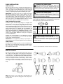
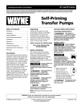
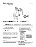
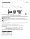
Bell & Gossett
Instruction Manual P81748
REVISION E
Series 100
Series HV
Series PR
Series 2"
Iron & Bronze Booster Pumps
Installation, Operation, & Service Instructions
INSTALLER: PLEASE LEAVE THIS MANUAL FOR THE OWNER’S USE.
Bell & Gossett Booster Pumps feature oil lubricated sleeve
bearings, a carbon/ceramic seal and a noise dampening spring
coupler. Bell & Gossett Booster Pump motors are designed
specifically for quiet operation and are built with thermal protection and drip-proof construction. The motor is nonover-loading at any point on the pump curve.
This pump is nonsubmersible, for indoor use only.
PUMP APPLICATION
Bell & Gossett Pumps may be used for water circulating applications in hydronic, solar and chilled water systems. Bell &
Gossett recommends that bronze constructed pumps be used
for pumping potable water. For other applications contact your
local Bell & Gossett Representative. Note that some local
codes require using a check valve in the supply line when recirculating potable water.
It has not been investigated, nor is it intended for use in swimming pool and marine areas.
SAFETY
INSTRUCTIONS
This safety alert symbol will be used in this manual and on the
pump instructions decal to draw attention to safety related
instructions. When used, the safety alert symbol means
ATTENTION! BECOME ALERT! YOUR SAFETY IS INVOLVED!
FAILURE TO FOLLOW THE INSTRUCTIONS MAY RESULT IN
A SAFETY HAZARD.
WARNING
BEFORE INSTALLING, USING OR
SERVICING THIS PRODUCT,
READ THE WARNING NOTES
AND INSTRUCTIONS IN
INSTRUCTION MANUAL.
FAILURE TO DO SO MAY
RESULT IN SERIOUS INJURY
OR PROPERTY DAMAGE
WARNING
RISK OF ELECTRIC SHOCK;
THIS PUMP HAS NOT
BEEN INVESTIGATED FOR
USE IN SWIMMING POOL
AND MARINE AREAS.
-NONSUBMERSIBLE PUMP-
P86313
DESCRIPTION
V56845
OPERATIONAL LIMITS
These pumps are designed to pump liquids compatible with
their iron or bronze body construction. Unless special provisions have been made by ITT Bell & Gossett, the operational
limits for Series 100, HV, PR and 2" Pumps are listed below.
Do not exceed these values.
Maximum Working Pressure:
125 psi
Maximum Operating Temperature: 225ºF
Electrical Rating:
115V, 60 Hz, 1PH
Motors with special electrical characteristics are available on
request. Contact your local Bell & Gossett Representative for
details.
Your Booster Pump should have these warning labels affixed
near the conduit box cover. If these warnings are missing or
illegible, contact your local Bell & Gossett Representative for
replacement labels.
SAFETY REQUIREMENTS
MECHANICAL SAFETY
ELECTRICAL SAFETY
WARNING: EXCESSIVE SYSTEM PRESSURE
HAZARD
The maximum working pressure of the pump is listed on
the nameplate – DO NOT EXCEED THIS PRESSURE.
Failure to follow these instructions could result in serious
personal injury, death and/or property damage.
WARNING: ELECTRICAL SHOCK HAZARD
Electrical connections are to be made by a qualified
electrician in accordance with all applicable codes, ordinances and good practices. Failure to follow these instructions could result in serious personal injury, death and/or
property damage.
WARNING: EXCESSIVE PRESSURE HAZARD –
VOLUMETRIC EXPANSION
The heating of water and other fluids causes volumetric
expansion. The associated forces may cause failure of system components and release high temperature fluids. This
can be prevented by installing properly sized and located
expansion tanks and pressure relief valves. Failure to follow
these instructions could result in serious personal injury,
death and/or property damage.
WARNING: ELECTRICAL OVERLOAD HAZARD
Three phase motors must have properly sized heaters
to provide overload and under voltage protection. Single
phase motors have built-in overload protectors. Failure to
follow these instructions could result in serious personal
injury, death and/or property damage.
THERMAL SAFETY
WARNING: EXTREME TEMPERATURE HAZARD
If the pump, motor, or piping are operating at extremely high or low temperature, guarding or insulation is
required. Failure to follow these instructions could result in
serious personal injury, death and/or property damage.
WARNING: HOT WATER HAZARD
When disassembling a gasket joint, always use a new
gasket upon reassembly. NEVER RE-USE OLD GASKETS.
Failure to follow these instructions could result in serious
personal injury, death and/or property damage.
WARNING: ELECTRICAL GROUNDING HAZARD
Adequate electrical grounding is required for the safe
operation of B&G Pumps. The use of grounded metal conduit assures this requirement. If the means of connection to
the supply-connection box (wiring compartment) is other
than grounded metal conduit, ground the pump back to the
service by connecting a copper conductor at least the size
of the circuit conductors supplying the pump to the green
grounding screw provided within the wiring compartment.
Failure to follow these instructions could result in serious
personal injury, death and/or property damage.
WARNING: RISK OF ELECTRIC SHOCK
Do not install this pump in swimming pool or marine
areas. Failure to follow these instructions could result in
serious personal injury, death and/or property damage.
REMOVAL OF THE PUMP FROM EXISTING SYSTEM FOR REPLACEMENT
WARNING: ELECTRICAL SHOCK HAZARD
Disconnect and lockout the power before servicing.
Failure to follow these instructions could result in serious
personal injury or death.
1. Close the valves on the suction and discharge sides of
the pump. If no valves have been installed, it may be necessary to drain the system.
2. Loosen the conduit box cover screw and remove the cover.
WARNING: UNEXPECTED START-UP HAZARD
Single phase motors are equipped with automatic
reset overload protectors. The pump can restart without
warning. Disconnect and lockout power before servicing.
Failure to follow these instructions could result in serious
personal injury, death and/or property damage.
3. Disconnect the electrical supply lines to the pump.
WARNING: HOT WATER HAZARD
Before draining the system, allow water to cool to
100°F max. open the drain valve (take precautions against
water damage) and leave the drain valve open until servicing
is complete. Failure to follow these instructions could result
in serious personal injury, death and/or property damage.
WARNING: ELECTRICAL SHOCK HAZARD
Be certain the electrical power is not present at the
motor leads before continuing. Failure to follow these instructions could result in serious personal injury or death.
2
WARNING: HIGH PRESSURE HAZARD
Pressure may be present in the pump body. This
pressure can be relieved by loosening the flange bolts and
shifting the pump assembly slightly to allow the pressurized water to escape. Failure to follow these instructions
could result in serious personal injury or death.
4. Remove the flange bolts and remove the pump from the
piping.
PUMP INSTALLATION
PUMP LOCATION
Bell & Gossett Booster Pumps should be installed where there
will be sufficient room for future inspection, maintenance and
service. It is highly recommended that service valves (shut-off)
also be installed on each side of circulator pumps to facilitate
servicing or replacing the pump without draining the system.
IMPORTANT: In closed systems, do not install and operate
Bell & Gossett pumps, 3D valves, suction diffusers, etc., without properly sized safety and control devices. Such devices
include the properly sized and located pressure relief valves,
expansion tanks and pressure, temperature, and flow controls. If the system is not equipped with these devices, consult
the responsible engineer or architect before operating.
WARNING: HOT WATER HAZARD
When disassembling a gasketed joint, always use
a new gasket upon reassembly. NEVER RE-USE OLD
GASKETS. Failure to follow these instructions could result
in serious personal injury, death and/or property damage.
WARNING: HOT WATER HAZARD
Make sure that each flange gasket remains seated in
the flange groove during and after installation. Failure to follow these instructions could result in serious personal
injury, death and/or property damage.
Apply torque in even increments to both flange bolts until the
value listed in the table below is reached. Both the suction and
discharge flanges must be torqued in this manner.
PUMP SUPPORTING AND PIPING
Install the suction and discharge flanges on the pipe ends
using Teflon ®* tape sealer or high quality thread sealant.
Minimize strain on the pump by supporting the suction and
discharge piping with pipe hangers near the pump. Line up the
vertical and horizontal piping so that the bolt-holes in both the
pump and pipe flanges are aligned. DO NOT ATTEMPT TO
SPRING THE SUCTION OR DISCHARGE LINES INTO POSITION. THIS MAY RESULT IN UNWANTED STRESS IN THE
PUMP BODY, FLANGE CONNECTIONS AND/OR PIPING. The
code for pressure piping, ANSI B31.1, lists types of supports
for various applications.
Ordinary wire or band hangers are not adequate to maintain
alignment. It is very important to provide strong, rigid support
for the suction and discharge lines.
IMPORTANT: Do not support the pump by its power pack. To
function properly, the motor power pack must not be strained.
Pump Series
Bolt Torque
Full turns of
the nut from
finger tight
100 With
Full Face
Flange Gasket*
100 With Ring
Flange Gasket
PR
HV
2"
150-180 in. lbs.
12.5-15 ft. lbs.
96-132 in. lbs.
8-11 ft. lbs.
96-132 in. lbs.
8-11 ft. lbs.
96-132 in. lbs.
8-11 ft. lbs.
96-132 in. lbs.
8-11 ft. lbs.
1-1/4
1
1
3/4
3/4
* No longer used.
WARNING: WATER LEAKAGE HAZARD
To prevent leakage, make certain that the flange
bolts have been adequately torqued. Failure to follow these
instructions could result in serious personal injury and/or
property damage.
PUMP FLANGES
New Bell & Gossett flanges gaskets must be installed between
the flanges of the pump body and suction and discharge
pipes. The gaskets should be clean and grease-free; old gaskets should never be reused.
*Teflon® is a registered trademark of E.I. DuPont de Nemours and Company.
MODE OF DISCHARGE
Bell & Gossett Pumps can be installed to discharge up, down,
left or right. The oiling ports must always be in the twelve
o’clock position (on top) with motor and bearing assembly in a
horizontal position. THE ARROW ON THE PUMP BODY MUST
POINT IN THE DIRECTION OF THE FLOW. If it becomes necessary to change the mode of discharge, refer to B&G
Instruction Manual HS-105-SM for specific instructions in
removing the motor and bearing assembly from the pump
body.
OIL PORTS
NOTE: The position of the conduit box is determined by the
model of the motor used. The oiling ports must always be in
the up position.
3
OPERATIONAL INSTRUCTIONS
WIRING INSTRUCTIONS
WARNING: ELECTRICAL SHOCK HAZARD
Disconnect and lockout the power before making
electrical connections. Failure to follow these instructions
could result in serious personal injury or death.
SYSTEM PREPARATION1
Prior to pump start up, closed heating and cooling systems
should be flushed with clean water and drained. The system
should then be filled with clean water having a PH between 7
and 9.
1. Remove the screws securing the conduit box cover (wiring
compartment) and lift off the cover. Attach the appropriate
size connector to the hole in the side of the conduit box.
LUBRICATION1
Although the new B&G pumps are test run at the factory, they
must be lubricated thoroughly before being placed in operation. Bell & Gossett supplies a high quality lubricant specifically for this purpose which can be purchased from any B&G
Representative (Part No. L23401). Proper lubrication procedurs are as follows:
1. PUMP BEARINGS – Fill the bearing frame according to the
oiling instructions decal. At the time of installation, add
approximately 1 oz. of B&G #20 weight non-detergent oil.
An SAE 20 (non-detergent) or 10W-30 oil may be substituted.
Re-lubrication is required at the start of each heating season, or every three months for continuous service. Relubricate with 1 teaspoon of oil. More frequent lubrication
may be required under adverse conditions such as high
ambient temperatures. Less frequent lubrication is required
if oil overflows from the reservoir.
2. MOTOR BEARINGS – Lubricate through the two motor oil
cups according to the lubrication decal. At the time of
installation the motor bearings use approx. 12 drops each.
At re-lubrication intervals fill each motor bearing with
approx. 6-8 drops. More or less frequent re-lubrication
may be required depending on the installation conditions.
NOTE: Over-oiling can cause motor mount deterioration and
may cause spillage onto surrounding surfaces. Deteriorated
motor mounts will lead to misalignment and excessive coupler
wear.
2. Using a minimum size 14 AWG copper electrical wire (refer
to your local code for wiring restrictions), wire the motor to
a 115 volt, 60 hertz, single phase power source.
TYPICAL WIRING INSTALLATION SCHEMATIC
POWER SOURCE: 115 VOLT, 60 HZ, 10
FUSIBLE DISCONNECT
OR CIRCUIT BREAKER
BY OTHERS
S
TO REMOTE
CONTROL
IF REQUIRED
L
N
PUMP
MOTOR
PUMP MOTOR
THERMALLY
PROTECTED
3. Connect the ground wire to the green screw inside the
conduit box.
NOTE: Single phase motors are protected with inherent overheating devices and do not require external overload protection.
NOTE: If a motor with special characteristics is selected, the
electrical rating of the power source must be the same as that
of the motor.
WARNING: ELECTRICAL SHOCK HAZARD
Be certain that all connections are secure and the
conduit box cover is closed before electrical power is connected. Failure to follow these instructions could result in
serious personal injury, death and/or property damage.
CAUTION: SEAL DAMAGE HAZARD
Do not run the pump dry – seal damage may occur.
Failure to follow these instructions could result in moderate
personal injury and/or property damage.
PRIMING AND STARTING
Do not run B&G circulator pumps dry. Before starting, the
pump must be filled with water. Air should be vented from the
system by means of a system air vent or by an alternate method.
SERVICE INSTRUCTIONS
ADDITIONAL PUMP REPAIR
1. Keep the pump and motor properly lubricated.
Refer to the following manuals for additional repair instructions for Bell & Gossett Iron & Bronze Booster Pumps:
2. If the system is to be exposed to freezing temperatures,
drain the pump.
PERIODIC INSPECTION
Inspect the pump regularly for leaking seals, worn gaskets,
and loose or damaged components. Replace or repair as
required.
© COPYRIGHT 2007 BY
ITT CORPORATION
PRINTED IN U.S.A. 12-07
THE ITT ENGINEERED BLOCKS SYMBOL AND
ENGINEERED FOR LIFE ARE REGISTERED
TRADEMARKS OF ITT CORPORATION
ITT
8200 N. Austin Avenue
Morton Grove, IL 60053
Phone: (847) 966-3700
Fax: (847) 966-9052
www.bellgossett.com
Coupler & Motor Mount Replacement . . . . . .#S15900, Rev. D
Booster Pump Service Manual . . . . . . . .#HS-105-SM, Rev. 3