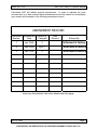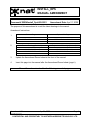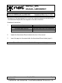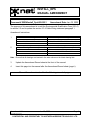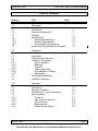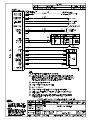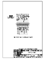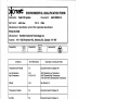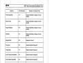
1
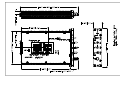
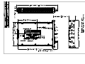
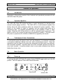
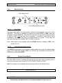
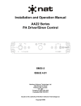
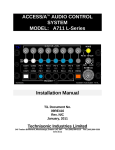
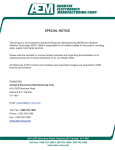
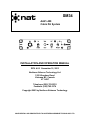
SM34
AA21-400
Cabin PA System
INSTALLATION AND OPERATION MANUAL
REV. 4.00 November 10, 2003
Northern Airborne Technology Ltd.
1925 Kirschner Road
Kelowna BC, Canada
V1Y 4N7
Telephone (250) 763-2232
Facsimile (250) 762-3374
Copyright 2003 by Northern Airborne Technology
CONFIDENTIAL AND PROPRIETARY TO NORTHERN AIRBORNE TECHNOLOGY LTD.
SM34 Rev. 4.00
AA21-400 Cabin PA System Manual
Periodically NAT will release manual amendments. In order to maintain the most
accurate and up to date manual these amendments should be carried out immediately
upon receipt and recorded on the following amendment record.
AMENDMENT RECORD
Amendment Amendment
Number
Date
Section(s)
Changed
Date
Entered
Entered By
1
Jan 18\05
2
Performed at factory
2
May 24\06
Pg iii, 1
Performed at factory
3
Apr 21\09
2
Performed at factory
Insert any Amendment Instruction sheets after this page.
Nov 10, 2003
ENG-FORM: 820-0109.DOT
Page ii
Amendment #2
May 24, 2006
CONFIDENTIAL AND PROPRIETARY TO NORTHERN AIRBORNE TECHNOLOGY LTD.
INSTALL_OPS
MANUAL AMENDMENT
Manual: SM34 (AA21-400)
Document # SM34\Install_Ops\809-0003
Amendment #: 3
Amendment Date: Apr 21, 2009
The purpose of this amendment is to add the latest drawings to the manual.
Amendment Instructions:
Remove Pages
Replace With Pages
2-5 Rev 4.00 Amendment 1
2-5 Rev 4.00 Amendment #3
1
2
Remove Drawings (Section 2)
Replace or add Drawings (Section 2)
AA21\400\403-0 Rev 1.00
AA21\400\905-0 Rev 1.00
AA21\400\403-0 Rev 1.01
AA21\400\905-0 Rev 1.10
3
Update the Amendment Record sheet at the front of the manual.
4
Insert this page into the manual after the Amendment Record sheet (page ii).
Manual Amendment ends after the following amended pages
Amendment #3
Apr 21, 2009
Page 1
ENG-FORM: 809-0109.DOT
CONFIDENTIAL AND PROPRIETARY TO NORTHERN AIRBORNE TECHNOLOGY LTD.
INSTALL_OPS
MANUAL AMENDMENT
Manual: SM34 (AA21-400)
Document # SM34\Install_Ops\809-0002
Amendment #: 2
Amendment Date: May 24, 2006
The purpose of this amendment is to correct the numbering sequence and add section
1.5 Accessories Required But Not Supplied to the table of contents.
Amendment Instructions:
Remove Pages
Replace With Pages
Title Section Page iii Rev 4.00
1-3 and 1-4 Rev 4.00
Title Section Page iii Rev 4.00 Amendment #2
1-3 and 1-4 Rev 4.00 Amendment #2
1
2
Update the Amendment Record sheet at the front of the manual.
3
Insert this page into the manual after the Amendment Record sheet (page ii).
Manual Amendment ends after the following amended pages
Amendment #2
May 24, 2006
Page 1
ENG-FORM: 809-0109.DOT
CONFIDENTIAL AND PROPRIETARY TO NORTHERN AIRBORNE TECHNOLOGY LTD.
INSTALL_OPS
MANUAL AMENDMENT
Manual: SM34 (AA21-400)
Document # SM34\Install_Ops\809-0001
Amendment #: 1
Amendment Date: Jan 18, 2005
The purpose of this amendment is to add the Environmental Qualification Form (521-0)
to section 2.5 and to update the section 2.3.4 Cable Wiring statement paragraph 1.
Amendment Instructions:
Remove Pages
Replace With Pages
2-1, 2-2 and 2-5 Rev 4.00
2-1, 2-2 and 2-5 Rev 4.00 Amendment #1
Remove Drawings/Documents (Section 2)
Replace or add Drawings/Documents (Section 2)
-
AA21\400\521-0 Rev 1.20
1
2
Note: Ensure that all drawings are inserted in the order shown on the latest drawing lists.
3
Update the Amendment Record sheet at the front of the manual.
4
Insert this page into the manual after the Amendment Record sheet (page ii).
Manual Amendment ends after the following amended pages
Amendment #1
Jan 18, 2005
Page 1
ENG-FORM: 809-0109.DOT
CONFIDENTIAL AND PROPRIETARY TO NORTHERN AIRBORNE TECHNOLOGY LTD.
SM34 Rev. 4.00
AA21-400 Cabin PA System Manual
Table of Contents
Section
Title
Page
1.0
Description
1.1
1.2
1.3
1.4
1.4.1
1.4.2
1.4.3
1.5
Introduction
Purpose of Equipment
Features
Specifications
Electrical Specifications
Physical Specifications
Environmental Specifications
Accessories Required But Not Supplied
2.0
Installation
2.1
2.2
2.3
2.3.1
2.3.2
2.3.3
2.3.4
2.3.5
2.3.6
2.4
2.5
Introduction
Unpacking and Inspection
Installation Procedures
Note to Installers
Warnings
Cautions
Cabling and Wiring
Post-Installation Checks
Adjustments
Continued Airworthiness
Installation Drawings
3.0
Operation
3.1
3.2
3.3
3.4
3.4.1
3.4.2
3.4.3
3.4.4
3.4.5
Introduction
Operation Specifics
Techniques of Voice Transmission
Basic operation
Power Up
Input Function Selection
Volume Control
Mode switches
Remote Power Switch
Nov 10, 2003
ENG-FORM: 820-0109.DOT
1-1
1-1
1-1
1-2
1-2
1-4
1-4
1-5
2-1
2-1
2-1
2-1
2-1
2-2
2-2
2-2
2-4
2-5
2-5
3-1
3-1
3-1
3-1
3-1
3-2
3-2
3-3
3-3
Page iii
Amendment #2
May 24, 2006
CONFIDENTIAL AND PROPRIETARY TO NORTHERN AIRBORNE TECHNOLOGY LTD.
SM34 Rev. 4.00
AA21-400 Cabin PA System Manual
Section 1.0 Description
1.1
Introduction
This manual contains information on the AA21-400 Cabin PA System.
Information in this section consists of purpose of equipment, features and specifications.
1.2
Purpose of Equipment
The AA21-400 Cabin PA control unit is designed to provide centralized control for an
aircraft’s internal and external PA systems. The design is contained in one panelmounted unit, with an illuminated faceplate. All audio and keylines are interfaced to
existing aircraft audio systems. Front panel switches provide selection of the various
operational modes of the AA21 and a potentiometer provides output volume control.
1.3
Features
The AA21-400 provides selection and control of internal and/or external PA system(s)
installed in an aircraft. The integrated 25 W speaker driver circuit is designed to drive
one 8 Ω speaker arrangement for internal paging. The AA21-400 also provides a lowlevel audio signal output that drives the input on a remote mounted power amplifier. The
output is designed to drive the NAT PA110/220 or PA250/700 series amplifiers. The
AA21-400 provides generation of wail and yelp siren audio on the low level output when
selected on the front panel.
A ‘+3 dB’ function allows the output level of the system to be varied by 3 dB. When the
input control line is grounded, the output is reduced by approximately 3 dB, and
removing the ground returns the system to full output.
Thermal protection is designed into the intermediate and final stage amplifiers to protect
the unit during very hot or extended high power operating conditions.
Four front panel switches provide selection of the various operational modes of the
AA21-400 as described in Section 3 of this manual (Operation).
Nov 10, 2003
Page 1-1
Amendment #2
May 24, 2006
CONFIDENTIAL AND PROPRIETARY TO NORTHERN AIRBORNE TECHNOLOGY LTD.
ENG-FORM: 800-0106.DOT
AA21-400 Cabin PA System Manual
SM34 Rev. 4.00
1.4
Specifications
1.4.1
Electrical Specifications
Power Supply
Linear DC (with reverse & over voltage protection):
Normal:
+27.5 Vdc nominal.
+22.0 Vdc minimum.
+30.3 Vdc maximum.
+18.0 Vdc emergency.
Input Current:
2.3 A max. full speaker power (35 W) @ +27.5 Vdc.
2.9 A max (35 W) with 0.40 A load on Switched
Power Output.
0.40 A idle @ +27.5 Vdc.
Backlighting:
150 mA max @ +27.5 Vdc.
Microphone:
150 Ohm amplified dynamic.
250 mVrms rated input level.
Automatic level controlled for maximum intelligibility
without distortion starts @ 130 mVrms.
Input Signals
ALC
Impedance
Music:
130 Ohm ± 10%.
Only one of Radio (Receive) or CD may be enabled at
a time.
Radio (Receive) 2.5 Vrms into 1k Ω ± 10%.
CD
1.0 Vrms into 11k Ω ± 10%.
PA key:
Active low. Max. current source 15 mA.
+3dB key:
Active open, isolated through optical relay. Max.
current source 13 mA. Reduces all audio, except
sidetone, by 3 dB when grounded. The output will be
reduced 2 to 3 dB if operating above 25 W on speaker
output, or above 6.5 Vrms on PA output.
Input to Input Crosstalk:
≤ -40 dB from rated output.
Page 1-2
ENG-FORM: 800-0106.DOT
Nov 10, 2003
Amendment #2
May 24, 2006
CONFIDENTIAL AND PROPRIETARY TO NORTHERN AIRBORNE TECHNOLOGY LTD.
SM34 Rev. 4.00
AA21-400 Cabin PA System Manual
Output Signals
Speaker:
Impedance and short circuit protected.
≤ 10% THD
20 W single tone into 8 Ω @ 50% duty cycle. Continuous.
20 W voice/music into 8 Ω @ 100% duty cycle. Continuous.
Note: Distortion is ≤ 3% THD at 10% of continuous
output power rating.
> 10% THD
35 W max. into 8 Ω with 2.5 Vrms into Radio (Receive) input.
Non-continuous (short term).
Audio bandwidth:
Mic input:
≤ 3 dB roll-off from 350 Hz to 3 kHz
Radio (Receive)/CD input: ≤ 3 dB roll-off from 350 Hz to 6 kHz
PA:
Selectable by internal jumper for either
PA110/220 (6.5 Vrms ± 10% into 600 Ω) or
PA250/700 (0.5 Vrms ± 10% into 600 Ω) for rated output.
Distortion:
≤3% THD at rated output.
Audio bandwidth:
Mic input:
≤ 3 dB roll-off from 350 Hz to 3 kHz
Radio (Receive)/CD input: ≤ 3 dB roll-off from 350 Hz to 6 kHz
Siren:
Only available on PA output (735 to 1620 Hz). Yelp
and wail modes with adjustable rates. Siren level
control provided for yelp/wail by one internal trimpot.
Sidetone:
Adjustable 0-100 mW into 600 Ω with ≤ 10% THD
Audio bandwidth: ≤ 3 dB roll-off from 350 Hz to 3 kHz
Input to Output
Crosstalk:
≤ -50 dB from rated output.
Audio Noise Level: ≤ -50 dB from rated output.
(without signal)
Switched Power:
+27.5 Vdc @ 0.40 Amps max. Over current protected.
Temperature Sensor
The unit contains a temperature sensor IC which
when triggered reduces the input signals by 3 dB.
The IC threshold is set to approximately 130° C.
Annunciator
Power On (illuminates green when active)
Nov 10, 2003
Page 1-3
Amendment #2
May 24, 2006
CONFIDENTIAL AND PROPRIETARY TO NORTHERN AIRBORNE TECHNOLOGY LTD.
ENG-FORM: 800-0106.DOT
AA21-400 Cabin PA System Manual
1.4.2
SM34 Rev. 4.00
Physical Specifications
1.4.3
Height
1.11 ± 0.03” (28.1 ± 0.8 mm)
Depth
6.53 ± 0.03” (165.9 ± 0.8 mm) behind panel (including
connector).
Width
4.96 ± 0.03” (126.0 ± 0.8 mm) behind panel.
5.75 ± 0.03” (146.1 ± 0.8 mm) in front of panel.
Weight
1.40 ± 0.07 lbs. (0.64 ± 0.03 kg)
Mounting
Std. Dzus Mounting (4 fasteners)
Faceplate
Engraved acrylic edge lit panel, with 28 Vdc backlighting.
Material/Finish
Chassis & cover: 5052-H32 brushed aluminum with
chromate conversion finish.
Heat sinks:
de-burred 6063-T6 aluminum with chromate
conversion finish.
Connector
Male filtered 25 pin D-subminiature with Positronics
V5 locking tabs.
Environmental Specifications
Operating Temp
-30° C to +55° C
Survival Temp
-55° C to +85° C
Humidity
> 95%
Altitude
25,000 ft.
DO-160D Env. Cat. B4-BAB[(SBM)(UF)]XXXXXXZBABB[TTX]MXXXX
TSO Compliance
TSO-C50c, RTCA DO170 Class II
(Applicable to units Serial # 1200 and up)
Page 1-4
ENG-FORM: 800-0106.DOT
Nov 10, 2003
Amendment #2
May 24, 2006
CONFIDENTIAL AND PROPRIETARY TO NORTHERN AIRBORNE TECHNOLOGY LTD.
SM34 Rev. 4.00
1.5
AA21-400 Cabin PA System Manual
Accessories Required But Not Supplied
Installation kit p/n AA21-400-IKC (crimp) or AA21-400-IKS (solder) is required to
complete the installation. They consist of the following:
AA21-400-IKC (crimp) NAT Part #:D25SV-IKC
Quantity
Description
NAT Part #
1
25
1
D-min 25 Socket housing
MS Crimp Socket
25 Pin JVL Hood/Locklever
20-21-025
20-26-901
20-29-250
AA21-400-IKS (solder) NAT Part #:D25SV-IKS
Quantity
Description
NAT Part #
1
1
D-min 25 Socket Solder Cup
25 pin JVL Hood/Locklever
20-20-025
20-29-250
End of section 1.0
Nov 10, 2003
Page 1-5
Amendment #2
May 24, 2006
CONFIDENTIAL AND PROPRIETARY TO NORTHERN AIRBORNE TECHNOLOGY LTD.
ENG-FORM: 800-0106.DOT
SM34 Rev. 4.00
AA21-400 Cabin PA System Manual
Section 2.0 Installation
2.1
Introduction
Information in this section consists of: unpacking and inspection procedures, installation
procedures, post-installation checks, and installation drawings.
2.2
Unpacking and Inspection
Unpack the equipment carefully and locate the warranty card. Inspect the unit visually
for damage due to shipping and report all such claims immediately to the carrier
involved. Note that each unit should have the following:
- AA21-400 Cabin PA System
- Warranty Card
- Operator’s Manual
- Release certification
Verify that all items are present before proceeding and report any shortage immediately
to your supplier.
Complete the warranty card information and send it to NAT when the installation is
complete. If you fail to complete the warranty card, the warranty will be activated on
date of shipment from NAT.
2.3
Installation Procedures
2.3.1
Note to Installers
The AA21-400 is intended for use as a cockpit-mounted control for an internal or
external aircraft PA system, where such a system is not installed to fulfill the
airworthiness requirements for the aircraft or an operating rule.
The AA21-400 is certified to RTCA DO-160D Section 20 (RF Susceptibility) Category T,
for installation in a well-protected electromagnetic environment such as an enclosed
avionics bay in an all-metallic aircraft. The equipment shall therefore not be installed to
satisfy the requirement of FAR 25.1423 for a Public Address system.
2.3.2
Warnings
Never ground any audio output line from the AA21-400 or permanent damage may result.
Always check ADF and compass calibration after installing external speakers or PA
amplifiers. Significant single cycle errors may be caused by the concentration of steel and
magnetic material. Do not bundle any lines from these units with transmitter coax lines.
Do not bundle any lines from this unit with 400 Hz synchro wiring, or AC power lines.
Nov 10, 2003
ENG-FORM: 800-0106.DOT
Page 2-1
Amendment #1
Jan 18, 2005
CONFIDENTIAL AND PROPRIETARY TO NORTHERN AIRBORNE TECHNOLOGY LTD.
AA21-400 Cabin PA System Manual
2.3.3
SM34 Rev. 4.00
Cautions
Use shielded cable exactly as shown and ground as indicated. All audio installations
can be severely degraded by incorrect wiring and shielding. Unusual buzzes, hums or
other background audio are symptomatic of multiple grounds, or noisy external systems
such as blowers or pumps sharing wiring with the audio system. Never operate any of
these units below their 8 Ω rated impedance.
2.3.4
Cabling and Wiring
All unshielded wire shall be selected in accordance with AC43.13-1B Change 1,
Paragraphs 11-76 through 11-78. Wire types should be to MIL-W-22759 as specified in
AC43.13-1B Change 1, Paragraphs 11-85, 11-86, and listed in Table 11-11. For
shielded wire applications, use Tefzel MIL-C-27500 shielded wire with solder sleeves
(for shield terminations) to make the most compact and easily terminated interconnect.
Follow the wiring diagrams in Section 2.6 as required.
Allow 3 inches from the end of the wire to the shield termination to allow the hood to be easily
installed. Note that the hood is a ‘clamshell’ hood, and is installed after the wiring is complete.
All wiring should be at least 22 AWG, except power and ground lines, which should be
at least 20 AWG. Ensure that all ground connections are clean and well secured. To
prevent system failure or inadequate equipment protection, power must be supplied
from a separate breaker or fuse and not connected to any other source.
2.3.5
Post-Installation Checks
2.3.5.1
Voltage/resistance checks
Do not attach the AA21-400 until the following conditions are met.
Check the following:
a)
P101 pins <1> <2> and <3> for +28 Vdc relative to ground.
b)
P101 pins <14>, <15> and <16> for continuity to ground (below 0.5 Ω).
c)
P101 pins <18>, and <22> (with switches open) for infinite resistance to ground (> 10 MΩ).
d)
P101 pin <5> to pin <7> for 4 – 6 Ω (typical).
Page 2-2
ENG-FORM: 800-0106.DOT
Nov 10, 2003
Amendment #1
Jan 18, 2005
CONFIDENTIAL AND PROPRIETARY TO NORTHERN AIRBORNE TECHNOLOGY LTD.
SM34 Rev. 4.00
2.3.5.2
AA21-400 Cabin PA System Manual
Power On checks
WARNING
The AA21-400 is a high power device, capable of producing
tones at very high volume levels. Ensure that all personnel
are well clear of the aircraft prior to keying the siren or PA.
Failure to adhere to this warning could cause injury to
personnel and/or damage to equipment. DO NOT conduct
the following tests inside an enclosed area (i.e. a hangar.)
a)
Install the Cabin PA system and remote amplifier(s) and speaker(s) as
applicable, and then power up the ship’s systems. Turn on all of the radios and
other accessories required for this system. Check that the POWER ON LED on
the AA21-400 illuminates when the power switch is selected to ON.
b)
From the front panel switches, select PA and EXT. Key the siren using the front panel
switch and remote Siren key as described in Section 3.4.4.1. The siren should sound
on the external PA speakers, and the level should be at maximum volume (the VOL
control fully cw). If the siren rate needs adjustment use the corresponding trimpot on
the top of the AA21-400. Refer to section 2.3.6.1 for details.
c)
Configure the audio system as required to allow connection of the pilot's mic to
the PA and key the cyclic switch for transmit. The mic audio should be heard on
the PA speakers. Adjust the front panel level control for the desired volume. Set
the front panel switch to RADIO, and check for correct radio operation and note
what volume settings will produce a suitable external paging level. USE CARE
TO AVOID FEEDBACK INTO THE MICROPHONE!
Note: A faint audio signal may be heard at the speaker (even when the system is not
paging) due to the very high gain of this system and stray coupling in the wiring.
It should not be audible in flight.
Nov 10, 2003
Page 2-3
ENG-FORM: 800-0106.DOT
CONFIDENTIAL AND PROPRIETARY TO NORTHERN AIRBORNE TECHNOLOGY LTD.
AA21-400 Cabin PA System Manual
2.3.6
SM34 Rev. 4.00
Adjustments
The unit ships from the factory with all internal adjustments set to the normal test levels.
Once installed in the aircraft, it may be desirable to change some of these settings to
best suit the local operating environment. The internal adjustments are accessible
through holes located on the top of the unit.
Level Adjustments
Sweep Rate
Adjustments
Configuration
Jumpers
2.3.6.1
Sweep Rate
The sweep rates for the wail and yelp modes of the siren are adjustable using the
appropriately marked pots. The yelp rate is adjustable from 48 cycles/min to 300
cycles/min, and the wail rate is adjustable from 5 cycles/min to 200 cycles/min. Rotating
a pot cw will increase the sweep rate, and ccw will decrease it.
2.3.6.2
Level Adjustments
The sidetone, mic, siren, receive, and internal speaker levels are all adjustable by
rotating the appropriate pots cw to increase the level, and ccw to decrease it. The
external speaker level is adjustable by rotating the appropriate pot cw to decrease the
level, and ccw to increase it.
The range adjustments for the potentiometers are given below:
External speaker level:
(60dB dynamic range)
Internal speaker level:
(90dB dynamic range)
S/T level:
(100dB dynamic range)
Page 2-4
Nov 10, 2003
ENG-FORM: 800-0106.DOT
CONFIDENTIAL AND PROPRIETARY TO NORTHERN AIRBORNE TECHNOLOGY LTD.
SM34 Rev. 4.00
2.3.6.3
AA21-400 Cabin PA System Manual
Mic level:
(60dB dynamic range)
Receive level:
(70dB dynamic range)
Siren level:
(70dB dynamic range)
Configuration Jumpers
The configuration options for the AA21-400 can be selected by installing jumpers as
shown below:
RX/CD:
Pins 1-2 :
Radio (Receive) input enabled,
CD input disabled
Pins 2-3 :
CD input enabled,
Radio (Receive) input disabled
EXT SPKR LEVEL :
2.4
Installed : 500 mVrms output level
Not installed : 6.5 Vrms output level
Continued Airworthiness
Maintenance of the AA21-400 is ‘on condition’ only. Periodic maintenance of this
product is not required.
2.5
Installation Drawings
DRAWING
REV.
DESCRIPTION
TYPE
SERIAL #
AA21\400\403-0
1.01
AA21-400 Cabin PA System
Interconnect
All
AA21\400\405-0
1.00
AA21-400 Cabin PA System
Connector Map
All
AA21\400\521-0
1.20
AA21-400 Cabin PA System
AA21\400\905-0
1.10
AA21-400 Cabin PA System
AA21\400\922-0
1.00
AA21-400 Cabin PA System
Mech. Installation 1015 – 1199
AA21\400\922-0
1.11
AA21-400 Cabin PA System
Mech. Installation 1200 and up
Environmental Qual Form 1200 and up
Faceplate
All
Section 2.0 ends after these Drawings
Nov 10, 2003
ENG-FORM: 800-0106.DOT
Page 2-5
Amendment # 3
Apr 21, 2009
CONFIDENTIAL AND PROPRIETARY TO NORTHERN AIRBORNE TECHNOLOGY LTD.
SM34 Rev. 4.00
AA21-400 Cabin PA System Manual
Section 3.0 Operation
3.1
Introduction
Information in this section consists of the functional and operational procedures for the
AA21-400 Cabin PA system.
3.2
Operation Specifics
The AA21-400 Cabin PA system provides a central adjustment for internal and/or
external aircraft paging functions. The AA21-400 is a self-contained amplifier that
directly drives the cabin speaker(s) and/or the external PA system amplifier. When
turned on, the system is ready for operation and will accept audio feeds or a
microphone input. An internally generated siren is also available in WAIL or YELP
modes. When the AA21-400 is turned on, a 28 Vdc switched signal is generated. This
signal is used to turn on the PA amp relay (if connected in system). The high current
DC power to operate the PA110/220 or PA250/700 is supplied by the aircraft.
3.3
Techniques of Voice Transmission
To successfully project the human voice over long distances, it is necessary to develop
a microphone technique different from the usual conversational manner. Place the
microphone with the upper lip touching the mouthpiece and talk clearly and distinctly,
with increased emphasis. Separate each word with noticeable pauses and keep the
voice level constant. A medium pitched voice is more easily understood and carries
farther than a bass voice.
3.4
Basic Operation
3.4.1
Power up
To activate the AA21-400 Cabin PA system, flip the POWER toggle switch up to the ON
position. The LED adjacent to the switch should illuminate.
Power Switch
Nov 10, 2003
Indicator LED
Page 3-1
ENG-FORM: 806-0105.DOT
CONFIDENTIAL AND PROPRIETARY TO NORTHERN AIRBORNE TECHNOLOGY LTD.
SM34 Rev. 4.00
3.4.2
AA21-400 Cabin PA System Manual
Input Function Selection
The Input Function switch is a two-position, locking switch on the front of the AA21-400
that is used to select between PA and Radio operation. When PA is selected, RADIO is
disabled, and vice versa. It is good practice to set this switch to PA when operating the
siren to avoid mixing incoming radio/CD audio with the siren audio output.
Input Function Switch
3.4.2.1
PA Operation
For external PA/Siren systems or internal paging functions, set the function switch on
the AA21-400 to PA. Key the microphone through the cyclic or hand mic switch, and
speak in a firm, clear manner.
3.4.2.2
Radio Operation
To set the system for radio rebroadcast functions, set the function switch on the AA21400 to RADIO. All audio delivered from the source (typically pilot’s or copilot’s headset)
will be broadcast from the PA system or internal speaker.
3.4.3
Volume Control
Volume Control
The volume control knob (VOL) on the front of the AA21-400 is used to adjust the level
of the selected output. Rotating the knob cw will increase the volume, and ccw will
decrease it. For external paging and rebroadcast operations, the volume should always
be set between half and full level. The setting for internal paging must be determined
by experiment to provide the desired coverage in the passenger area and to prevent
feedback.
Nov 10, 2003
Page 3-2
ENG-FORM: 806-0105.DOT
CONFIDENTIAL AND PROPRIETARY TO NORTHERN AIRBORNE TECHNOLOGY LTD.
SM34 Rev. 4.00
3.4.4
AA21-400 Cabin PA System Manual
Mode Switches
Siren Mode Switch
Internal/External Mode Switch
3.4.4.1
Siren Mode
The siren mode switch is a three position, centre-off locking switch on the front of the
AA21-400. The siren is operated by selecting the mode (YELP or WAIL) and then
activating a remote Siren key. The siren will sound only as long as the mode is selected
to WAIL or YELP and the Siren key is activated. It should be noted that in some
installations, the remote Siren key is connected directly to ground. In this case, the
siren will sound as soon as either YELP or WAIL is selected.
Note: Siren audio is only available when the INT/EXT switch is selected to EXT. (See
section 3.4.4.2.)
3.4.4.2
Internal/External Mode Switch
The INT/EXT mode switch is a two position locking switch that routes the selected audio
either to the internal 8Ω speaker (INT) or to the PA via an amplifier such as the NAT
PA250/700 or PA110/220 (EXT).
3.4.5
Remote Power Switch
The AA21-400 provides a switched 28 Vdc low current output that is typically used to
control the dc power circuit of an NAT PA110, PA220, PA250 or PA700.
Note: This output is only available when the power switch is in the ON position.
End of section 3.0
Nov 10, 2003
Page 3-3
ENG-FORM: 806-0105.DOT
CONFIDENTIAL AND PROPRIETARY TO NORTHERN AIRBORNE TECHNOLOGY LTD.