1
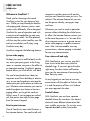
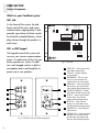
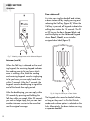
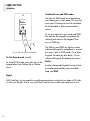
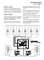
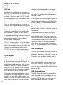
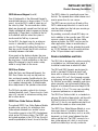
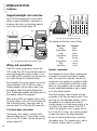
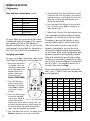
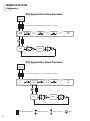
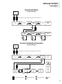
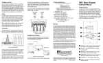
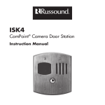
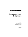
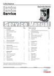
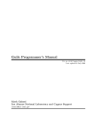
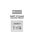
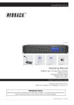
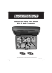
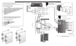
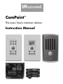
ComPoint™
The music lover’s intercom solution
Instruction Manual
SAFETY PRECAUTIONS
Safety Precautions
For your safety, please read and follow these precautions before installing or using this product:
➤ Read instructions. Read and understand all the applicable instructions before installing or operating the
product.
➤ Retain documents. Keep this manual in a convenient place for reference.
➤ Heed warnings. Be aware of all warnings on the product and in the instructions.
➤ Follow instructions. Install and use this product only as described in the instructions. Don’t try to use this
product in ways it wasn’t designed for.
➤ Install in suitable locations. Except for the ISK3 Door Station, install this product only indoors. Don’t
expose interior devices to the weather or harsh environmental conditions such as continuous sunlight,
excessive humidity, or rain.
➤ Keep product dry. Don’t use the product near water; for example, near a bathtub, washbowl, kitchen sink,
laundry tub, in a wet basement, or near a swimming pool. Also, do not handle the product when your hands
are wet or damp.
➤ Avoid heat. Locate the product away from heat sources such as radiators, heat registers, stoves or other
appliances (including amplifiers) that produce heat.
➤ Use the right power. Don’t connect the system components directly to electrical line voltage. Use only the
power adapter provided with the product, described in the product specifications or installation instructions,
or as marked on the product.
➤ Ground product properly. Make sure the product’s means of grounding or polarization is not defeated.
➤ Keep product clean. From time to time, wipe off the product with a clean soft cloth. Don’t use abrasive
materials, thinners, alcohol or other chemical solvents or materials.
➤ Avoid spills and foreign objects. Make sure liquids and objects don’t get into the product through any
openings.
➤ Get professional service. Have the product serviced only by qualified service personnel when:
• Liquids have spilled or objects have fallen into the product
• The product has been exposed to rain
• The product doesn’t appear to operate normally
• The product is damaged
Don’t attempt to service the product yourself. Doing so will void the warranty.
Russound will assume no liability for failure to understand installation or operating instructions for this product
or for its improper installation or use.
If you have any questions, please call Russound at 1.800.638.8055 or 603.659.5170.
2
TABLE OF CONTENTS
USER SECTION
Speaker connections
18
Welcome to ComPoint™!
4
Doorbell connections
19
About this manual
5
Door strike release connections
19
Hub modular connections
19
What’s in your ComPoint system
6–7
ISH1 Hub
6
ISK1 or ISK2 Keypad
6
Hub ID numbers
20
ISK3 Door Station
7
Doorbell chimes
20
ISDR1 Door Strike Release Module
7
Zone and door station labels
21
Assigning zone labels
22
Programming
20–25
Using your ComPoint system
8–14
Things you’ll need to know
8
Assigning door station labels
23
Paging
8
Viewing system information
23
Intercom
9
Restoring factory settings
23
Door station call
10
Programming flow charts
24–25
Door strike release
11
Detailed function descriptions
26–29
Listen mode
12
Communication priority levels
26
Do Not Disturb mode
13
Paging
26
Combined Listen and DND modes
14
Intercom
26
Door station call
27
Door strike release
28
Listen mode
28
Audible keypad volume level indication
29
INSTALLER SECTION
About this section
15
Product summary
15–17
ISH1 Hub
16
System busy
29
System keypads
16
Do Not Disturb (DND) mode
29
ISK1 Basic Keypad
16
Keypad backlight
29
ISK2 Advanced Keypad
16
System function test
30
ISK3 Door Station
17
Troubleshooting chart
31
ISDR1 Door Strike Release Module
17
Device installation and trim
17
REFERENCE SECTION
Keypad backlight color selection
18
Technical specifications
32
Accessories
33
Warranty
33
Wiring and connections
110 punch-down connections
18–19
18
3
USER SECTION
Introduction
Welcome to ComPoint™!
Thank you for choosing a Russound
ComPoint system for your home or business. While you may already be familiar
with paging and intercom systems, each
system works differently. We’ve designed
ComPoint for ease of operation and with
a unique set of capabilities to meet your
communication needs. You’ll be pleased
with the way the system simplifies your life,
and we’re confident you’ll enjoy using
ComPoint every day.
ComPoint integrates the following features:
System-wide paging
Perhaps you want to call the family to dinner, move your party guests to the living
room, or summon everyone in the office to
an important meeting. ComPoint’s paging
feature allows you to do all this with ease.
You can let everybody know about an
important event like a birthday or anniversary, or you can broadcast a message for
someone to pick up the phone or come see
you. Whatever announcement you want to
make throughout your home or business,
paging allows you to get the word out.
What’s more, if you’re paging an individual, that person can reply to your page
from the nearest keypad.
Point-to-point intercom
One of ComPoint’s most useful functions is
the intercom feature. You need to talk with
4
someone in another room out of earshot,
and you can’t leave the room you’re in. The
solution? The intercom feature lets you contact the person directly, saving you steps
and time.
Whenever you want to reach a particular
person without disturbing the whole house
or office, the intercom feature connects you
to the room the person is in. You can think
of an intercom session as a private conversation while paging is a public announcement. Also, intercom enables two-way
conversations, whereas paging is intended
for one-way communication.
Door station call and reply
With ComPoint at your service, you don’t
have to run to the door every time the
doorbell rings. If you can’t get to the door
right away, the door station call function
gives you the convenience of answering the
door from any room.
At any keypad you can have a two-way
conversation with the caller to find out who
it is and the purpose of their visit—before
you even approach the door.
Doorbell chimes
With ComPoint, you can have separate
doorbell chimes for two doors. You have a
choice of seven different chime tones that
your installer can assign. Or you can use a
separate doorbell system if you prefer.
USER SECTION
Introduction
Door strike release
Integration with your music system
Did someone in the family forget their keys?
Did a friend drop by? ComPoint offers an
optional module that works with a door
strike release to let you admit your visitor
from any keypad without going to the door
in person. Imagine the convenience of not
having to leave the baby or interrupt an
important task to go and open the door for
your visitor.
For even greater convenience, your
ComPoint system can share the speakers in
your multiroom audio system. When active,
ComPoint switches the speakers over to the
keypad amplifiers in the affected rooms,
momentarily interrupting the audio program. When the activity ends, the speakers
resume playing your audio program.
Listen to another room
Need to keep an ear open for someone?
Wondering what the kids are doing? With
ComPoint you’re within earshot of any
other room. Listen mode keeps you in touch
with what’s going on in any room with a
keypad.
Do not disturb
When you’ve tucked your kids into bed or
you need peace and quiet in the study to
concentrate, you can switch the room keypad to Do Not Disturb. This prevents all
communication events from being heard in
that room.
Hands free
One of the nicest features in ComPoint is
the ability to reply to intercom calls without
having to touch the keypad. And when the
delivery person rings your doorbell, they
can answer your reply without having to
press the Call key again.
About this manual
This section of the manual is for you, the
user. It explains what you need to know to
use and enjoy your ComPoint system.
Reading these first several pages will help
you get the most out of your system. As you
learn, share your discoveries with others in
your family or office so they too can enjoy
using ComPoint.
The Installer section that follows provides
more technical information and gets into
the nitty gritty of how the system works. It’s
intended for your installer, but you’re welcome to read it, too.
We recommend keeping this manual in a
safe, accessible place so you can refer to it
when you need to.
5
USER SECTION
System Components
What’s in your ComPoint system
ISH1 Hub
As the heart of the system, the hub
keeps track of the zones and routes
communications appropriately. It also
provides your choice of chime sounds
for the built-in doorbell feature, which
plays chimes through the speakers in
each room.
DOORBELL CHIME
GAIN
NEWMARKET, NH USA
ISH1
ISK1 or ISK2 Keypad
PROGRAM OPTIONS
0=DOWN / 1=UP
15VDC
MIN
MAX
1-3 = DOOR 1 CHIME
SWITCH 4 = CHIME VOLUME
UP = 50% MAX KEYPAD OUTPUT
DOWN = KEYPAD ADJUSTABLE
5-7 = DOOR 2 CHIME
8 = NOT USED
1
DOOR BELL CHIME
DS1
3.5A MAX
3
5
DS2
HUB ID
SWITCH 1-3
HUB 1 = 000
HUB 2 = 001
HUB 3 = 010
HUB 4 = 011
HUB 5 = 100
HUB 6 = 101
NONE = 000
CHIME 1 = 001
CHIME 2 = 010
CHIME 3 = 011
CHIME 4 = 100
CHIME 5 = 101
CHIME 6 = 110
CHIME 7 = 111
#4
RUN
UPDATE
DOOR 1
LINK
IN
2
4
6
The keypads control the system and
serve as your interior communication
points. A simple array of keys lets you
easily operate your system. In addition, each keypad contains a built-in
microphone and a small amplifier to
power one or two speakers.
OUT
DOOR 2
FIRMWARE
UPDATE PORT
MADE IN CHINA
Fig. 1. ISH1 Hub
1 ZONE KEYS – Select and indicate
zones (Basic Keypad only)
2 TALK KEY – Initiates outgoing
communications
3 MICROPHONE – Picks up user’s
voice for communications and
ambient sounds for Listen mode
1
6
2
5 DO NOT DISTURB KEY – Enables
and disables Do Not Disturb mode
6 DISPLAY – Shows zone and door
station labels; also indicates
modes (Advanced Keypad only)
3
7
4
8
7 NEXT KEY – Scrolls forward
through lists and installer menus
on display (Advanced Keypad only)
5
9
8 VOLUME KEYS – Control keypad
output volume
Fig. 2. ISK1 Basic and ISK2 Advanced Keypads
6
4 DOOR KEYS – Select and indicate
door stations; also activate door
strike release (Basic Keypad only)
9 PREVIOUS KEY – Scrolls backward
through lists and installer menus;
also activates door release with
Next key (Advanced Keypad only)
USER SECTION
System Components
ISK3 Door Station
ISDR1 Door Strike Release Module
Designed for outdoor placement, the door
This optional module provides a connection
stations provide communication links to
point for a separate door strike release
visitors outside. Each weatherproof door
unit, making it possible to unlock the door
station contains a built-in microphone and
from any keypad.
a speaker for two-way communication and
features a simple yet elegant one-key
design.
1
Fig. 4. ISDR1 Door Strike Release Module
2
3
Fig. 3. ISK3 Door Station
1 MICROPHONE AND SPEAKER – Enable twoway communication
2 CALL KEY – Rings doorbell and initiates
communication
3 WEATHERPROOF COVER – Protects internal
components
7
USER SECTION
Operation
Using your ComPoint system
ComPoint is easy and fun to use. You’ll find
these instructions simple to follow. Take a
little time to get familiar with them so you
can start enjoying your system right away.
Things you’ll need to know
With ComPoint, we refer to areas with keypads as zones. A zone may be a single
room or an area with more than one room,
such as a kitchen and dining area.
Every communication has a sender and a
receiver. With ComPoint, we call any zone
that initiates a communication the sending
zone. The zone or zones to which the communication is sent are receiving zones,
even though they may reply to the initial
communication. For an intercom session,
the receiving zone is also the target zone.
In ComPoint, paging is the default method
of communication. Different communication
functions have different levels of priority.
Paging is not allowed when there is a door
station call or intercom session in progress.
An intercom session is not allowed when
there is a door station call or page in
progress. Also, a door station call takes
precedence over paging and intercom sessions and thus interrupts them.
Your ComPoint system is configured with
either ISK1 Basic or ISK2 Advanced keypads. The way you use your system and the
way it gives you information depends on
8
which keypads you have. We explain how
both types work.
With either keypad, pressing the Talk key
sounds a ping tone in the receiving zones
to announce your message. Releasing the
Talk key sounds a double ping.
If the system is already in use when you try
to send a page or start an intercom session, the Talk key blinks red for 7 seconds
to let you know the system is busy. Also, the
Advanced Keypad indicates Busy on its
LCD panel.
Paging
Paging lets you
send an
announcement
throughout your
home or business from any
keypad. To send
a page, simply
press and hold
the Talk key (figure 5), then
speak. Release
the key when
you’re done
speaking.
Fig. 5. Using the Talk key for paging
Your page will be heard in all zones except
those that are in Do Not Disturb mode. For
privacy and to avoid disturbing your neighbors, your page will not be heard at either
door station.
USER SECTION
Operation
Paging (cont’d)
If a zone key is lit red on the Basic Keypad,
press the key to deselect that zone before
you press the Talk key to send a page.
On the Basic Keypad, press and release a
zone key to select the target zone (figure
6). The key lights up red to indicate the
zone is selected.
If a zone label appears in the display on
the Advanced Keypad, use the Next or
Previous key to select Page before you
press the Talk key.
All keypads indicate which zone is sending
a page, so you’ll know where it’s coming
from. The zone indication remains for 30
seconds after the Talk key is released to
simplify replying to the page.
The keypads in the receiving zones also
sound a double ping when the Talk key is
released. This lets you know the person
sending the page is done speaking and
you can reply to the page. Within 30 seconds, simply press and hold the Talk key
and speak. Your reply will be heard only
in the zone that sent the page.
If you wish to reply to the page after the
30-second limit, you can use the intercom
function described below or a return page
to send your reply.
Intercom
Unlike a system-wide page, an intercom
session occurs only between two zones. To
use this feature, select a target zone on a
keypad. Press and hold the Talk key and
speak. Release the Talk key when you’re
done speaking.
Fig. 6. Selecting a target zone on the Basic Keypad
If the selected target zone is in Do Not
Disturb mode, the zone key and DND key
blink rapidly for 7 seconds.
On the Advanced Keypad, select a target
zone by using the Previous or Next key to
scroll through the list of available zones
until the display shows the zone you want
for the intercom session (figure 7).
If the selected zone is in Do Not Disturb
mode, the display alternately shows the
zone label and DND at 1-second intervals
and the DND key blinks rapidly for 7
seconds.
9
USER SECTION
Operation
Door station call
A visitor can ring the doorbell and initiate
a door station call by simply pressing and
releasing the Call key (figure 8). When the
Call key is pressed, all keypads indicate the
calling door station for 15 seconds. The D1
or D2 key on the Basic Keypad blinks red
and the display on the Advanced Keypad
shows Door1, Door2, or an installerassigned door label (figure 9).
Fig. 7. Selecting a target zone on the Advanced Keypad
Intercom (cont’d)
When the Talk key is released on the sending keypad, the receiving keypad indicates
the sending zone to let you know which
zone is sending. Also, both the sending
and receiving keypads sound a single ping
to let you know you can reply hands free
within 7 seconds. After the 7 seconds, the
keypads sound a double ping to signal the
end of the hands-free reply period.
After the double ping, you can reply within
30 seconds by pressing and holding the
Talk key while you speak. After 30 seconds
you can no longer reply, but you can start
another intercom session to the zone that
sent the original message.
10
Fig. 8. Using the Call key on a Door Station
The keypads also sound a doorbell chime,
as long as they aren’t in Do Not Disturb
mode and a chime option is selected on the
hub. Alternatively, the door station can ring
a separate doorbell.
USER SECTION
Operation
station pings twice to indicate the
time is up.
If more than 15 seconds have passed
since the door call, you can reselect
the door station and press the Talk
key to start a new session. This does
not ring the doorbell.
Door strike release
If your ComPoint system includes
optional ISDR1 Door Strike Release
Modules, you can activate them from
Fig. 9. Door call indication on Basic and Advanced keypads
a keypad to unlock the doors. The
ISDR1 itself does not unlock the door;
Door station call (cont’d)
rather, it provides a switch to control a
A door station call takes precedence over
separate door strike release unit to unlock
paging and intercom sessions and thus
the door.
interrupts them if they’re in progress when
To activate a Door Strike Release Module
the Call key is pressed.
from a Basic Keypad, press and hold the
To reply to a door station call, press and
corresponding door station key for 3 sechold the Talk key on a keypad within 15
onds (figure 10).
seconds and speak. Release the Talk key
when you’re done speaking. When you
release the Talk key, the door station sounds
a single ping to let the caller know they can
answer your reply.
Note: You must use the Talk key to reply
to a door station call. For your privacy,
ComPoint doesn’t allow a hands-free reply
to a door station call.
After you reply to a door station call, the
caller has 7 seconds to answer your reply
hands free. After 7 seconds, the door
Fig. 10. Releasing a door strike on the Basic Keypad
11
USER SECTION
Operation
Door strike release (cont’d)
Listen mode
The module then activates for 3 seconds
and the keypad and door station confirm
activation with a buzz tone.
You can use your ComPoint system to continuously listen to any single zone from one
or more other zones. To do this, first turn
on a keypad microphone in the zone you
want to listen to, then select that zone on
one or more other keypads.
To activate the Door Strike Release Module
from an Advanced Keypad during a door
call, press and hold both the Previous and
Next keys at the same time for 3 seconds.
The module then activates for 3 seconds
and the keypad and door station sound a
buzz tone to confirm activation.
To activate the Door Strike Release Module
from an Advanced Keypad when there is
no current door call session, first press the
Previous or Next key to scroll through the
list to the door label (figure 11). Then press
and hold both keys for 3 seconds.
Door1
1
Other communication events have priority
over Listen mode but only temporarily
interrupt it.
To turn on a zone microphone, select that
zone on its own keypad. The Talk key lights
up red to indicate the keypad’s microphone
is active. On a Basic keypad, the zone key
blinks (figure 12) and on an Advanced
Keypad, the zone label changes to MicOn
after 2 seconds (figure 13). Note: Only one
zone microphone can be on at once.
Door1
2
Fig. 12. Basic Keypad Microphone On indication
Fig. 11. Releasing a door strike on the Advanced Keypad
12
USER SECTION
Operation
gle between the zone label and Listn as
long as the active zone is selected.
To disable Listen mode from either type of
keypad, press any key other than Volume
Up or Volume Down in the zone you are
listening to. Listen mode cannot be disabled
from any other zone. The volume keys are
reserved for adjusting the keypad volume.
Fig. 13. Advanced Keypad Microphone On indication
Listen mode (cont’d)
Listn
To listen to the zone with the active microphone from a Basic Keypad, press the zone
key (figure 14). The key blinks three times
and then remains lit red to indicate selection of the zone with the active microphone.
Fig. 15. Selecting Listen mode on the Advanced Keypad
Do Not Disturb mode
Fig. 14. Selecting Listen mode on the Basic Keypad
To listen to the zone with the active microphone from an Advanced Keypad, press
the Previous or Next key to select the zone
(figure 15). The display will alternately tog-
The Do Not Disturb (DND) feature allows
you to prevent pages, intercom sessions,
door station calls, and doorbell chimes
from being heard in a zone. Thus, you can
use DND mode to prevent interruption of a
multiroom audio program in that zone.
To turn on DND mode, press and release
the DND key (figure 16). The DND key
lights up red to indicate the zone is in
DND mode.
13
USER SECTION
Operation
Combined Listen and DND modes
You can use DND mode on a keypad you
are listening to in Listen mode. This way the
zone you’re listening to won’t be disturbed
by the doorbell or other communication
events.
To set up a zone for Listen mode and DND,
first activate the keypad’s microphone by
selecting that zone on the keypad. Then
turn on DND key.
Fig. 16. Selecting Do Not Disturb mode
Do Not Disturb mode (cont’d)
To cancel DND mode, press any key on the
keypad other than Volume Up or Volume
Down.
The Talk key and DND key light up red to
indicate the keypad’s microphone is on and
the zone is also in DND mode. On a Basic
Keypad, the zone key also blinks. On an
Advanced Keypad, the display also shows
MicOn.
Another Advanced Keypad listening to that
zone alternately displays the zone label,
Listn, and DND.
Enjoy!
With ComPoint, we’ve created a versatile communication system that we hope will fit right
in with your lifestyle. We’re sure you’ll find ComPoint very useful and a pleasure to use.
14
INSTALLER SECTION
Product Summary
About this section
This section of the manual provides technical
information for installing and programming the
ComPoint system. It also provides detailed functional descriptions of the system components.
Product summary
The ComPoint system uses one or more central
hubs, each of which supports up to 6 keypads.
Each keypad is addressable by its own unique
ID number assigned by the hub.
ComPoint connects with CAT-5 cable, which
conveys power, ground, audio bus, and data
between the components. The system end-toend length limit for the CAT-5 cable is 250 feet
(76 m).
The system can include one or two door stations connected to hub #1. Each door station
has its own unique ID number, permanently
assigned in the system firmware.
Each door station may also have a door strike
release module wired in line between the hub
and the station.
Simple system programming is required to
assign the hub ID numbers, doorbell chimes,
and when ISK2 Advanced Keypads are used,
zone and door labels.
ISK2
ISH1
ISPS
ISK3
ISK3
ISDR1
ISDR1
Fig. 17. Six-zone ComPoint system with Advanced Keypads and Door Strike Release Modules
15
INSTALLER SECTION
Product Summary
ISH1 Hub
As the central controller for the ComPoint system, the ISH1 Hub performs all communications
routing. It addresses each keypad by sending a
message on the status wire in the CAT-5 cable
to give the keypad its own ID number according
to the port it’s connected to.
The hub has 6 zone keypad ports. Up to 6 ISH1
Hubs can be linked together for a maximum of
36 zones. With multiple hubs, each hub must be
assigned a unique ID number during installation.
The hub also has ports for 2 door stations. In a
system with multiple linked hubs, only the hub
with ID number 1 supports the door stations.
A separate doorbell chime tone can be selected
on hub 1 for each door. These chime selections
take effect for the entire system and play
through all the zone keypads.
The hub’s firmware contains a list of zone labels
for display on the ISK2 Advanced Keypads. The
labels are assigned to zones by the installer and
stored in nonvolatile memory within the hub.
The ISH1 hub uses an external power supply to
conserve chassis space. It also has a port for
updating the system firmware from a computer.
System keypads
ComPoint keypads are designed to be simple,
intuitive interfaces for the user. Each model has
a Talk key, volume keys, and a DND key for setting the zone in Do Not Disturb mode. Both
models have installer-selectable amber or green
backlighting that turns on when the system is
used and turns off after the system is inactive
for 60 seconds. A built-in microphone with automatic gain control picks up the user’s voice.
The keypads require external speakers, which
are driven by the keypad amplifiers for communications. By using built-in speaker relays, the
keypads can share the speakers used in a multiroom audio system. When ComPoint activates,
16
the relays switch the speakers to the keypad
amplifiers in the affected zones, momentarily
interrupting the audio pprogram. When the activity ceases, the speakers are switched back to
the audio system.
In the absence of a multiroom audio system, or
in zones that are not shared with an audio system, the keypads can be connected directly to
in-wall, in-ceiling, or surface-mounted speakers
through concealed wiring.
The keypad amplifier is monaural, but the relay
passes stereo signals from the audio system to
the speakers.
The keypad volume keys adjust the listening
level for communications by controlling the keypad’s amplifier output. They have no effect on
the room volume for a connected audio system.
The volume keys signal the hub to send a ping
tone as an audible cue for the volume level
when there is no communication taking place.
Once the volume adjustment reaches either end
of the range, the ping tone no longer sounds.
ISK1 Basic Keypad
The ISK1 Basic Keypad is designed for use in a
system with up to six zones, since it cannot
indicate or select zones other than 1 through 6.
Pressing a zone key selects a target zone for
an intercom session.
Certain keys change to red to indicate zone or
door station selection, incoming page or intercom, door station call, or system busy. When
another zone originates a page or intercom session, that zone is indicated by a red-backlit zone
key on the ISK1.
ISK2 Advanced Keypad
The ISK2 Advanced Keypad has enhanced features to provide more user feedback and support a larger system than the ISK1. It uses a 5character LCD text display to show zone and
door station labels and other information.
INSTALLER SECTION
Product Summary/Installation
ISK2 Advanced Keypad (cont’d)
One of the benefits of the Advanced Keypad is
unrestricted intercom on large systems (7 to 36
zones), since the ISK2 is able to select any of
the zones by label. The zone and door station
labels are dynamically served from the hub and
listed in alphabetical order to appear on the keypad display. A Page label is included in the list
as the default selection when the system is
inactive and the Talk key is pressed.
On the ISK2, the target zone for an intercom
session is selected by scrolling through the
zone list. Pressing and holding the Previous or
Next key scrolls through the list with a half-second delay between zone labels.
A bar graph on the display indicates the zone
volume level visually in conjunction with the audible ping tones. A small pushbutton on the front
edge of the keypad is used to enter a setup
mode to assign labels to the zones.
ISK3 Door Station
Unlike the Basic and Advanced Keypads, the
ISK3 Door Station has only one key and contains an internal speaker. Amplification for the
speaker is built in as with the keypads but there
is no speaker interrupt relay. A potentiometer
allows adjustment of the speaker volume level.
The ISK3 also provides contacts for closing a
standard doorbell circuit. These close for a minimum of 4 seconds to activate an existing doorbell or other device.
ISDR1 Door Strike Release Module
The optional ISDR1 Door Strike Release Module
provides relay contacts for activating a door
strike release obtained from another source.
The module connects in the CAT-5 line between
a hub and an ISK3 door station. The ISDR1 can
be located anywhere in the CAT-5 line, though it
would be preferable to have it close to the door.
The ISDR1 obtains its operational power from
the hub. The separate door strike release must
receive power from its own source.
The ISDR1 passes signals on all leads of the
CAT-5 cable except one which is used to activate the module from the hub upon receiving a
command from a keypad.
By providing a normally closed (NC) relay contact in addition to the normally open (NO) and
common contacts used for the door strike
release activation, the ISDR1 can be used for
other applications where a versatile relay is
needed. The ISDR1 can be activated by providing 15 VDC between two of the eight positions
in the 110 punch-down input connector.
Device installation and trim
The ISH1 Hub is designed for surface mounting
or installation in a structured wiring panel. It
should be located near an electrical outlet.
The ISK1 and ISK2 Keypads are designed to
install in standard US electrical plastic wall
boxes with an internal volume of at least 18
cubic inches (295 cm3). Each keypad occupies
a single gang and accepts a Decora® wall plate.
For the best accessibility, viewability, and microphone reception, we recommend installing the
keypads at a standard thermostat height of 58
to 60 inches (1.5 m). This may vary according
to personal preferences or requirements.
The ISK3 Door Station installs in a standard single-gang US electrical deep plastic wall box with
an internal volume of at least 22 cubic inches
(360 cm3). It has its own weather-resistant front
plate and thus needs no other cover plate.
The ISDR1 Door Strike Release Module is a surface-mount device. It should be located in an
accessible area near the door, such as an attic,
basement, or closet space between the door
station and the hub. The ISDR1 connects to a
door strike release unit, which in most cases
would be installed by a security contractor.
17
INSTALLER SECTION
Installation
Keypad backlight color selection
Each ComPoint keypad can be set to either
amber or green backlighting, selected by a
miniature slide switch on the bottom edge of
one of the circuit boards (figure 18).
ISK1
BR BR/W G G/W O O/W BL BL/W
BR BR/W G G/W O O/W BL BL/W
BR BR/W G G/W O O/W BL BL/W
Fig. 19. 110 punch-down connection
The keypad wire functions are as follows:
Amber
Green
ISK2
Fig. 18. Keypad backlight color selector switch
Wiring and connections
ComPoint system components connect with
CAT-5 cable. Run CAT-5 from the hub location to
every keypad and door station location. If you
are installing ISDR1 modules, loop the door station cables through the module locations.
Each keypad in the system requires one or two
external speakers. If the ComPoint system is
sharing speakers with an audio system, loop
the speaker cables through the keypad locations. If dedicated speakers are being used, run
the speaker cables to the keypads.
When running CAT-5 and speaker cables, avoid
AC power wiring. If you must run the cables parallel to electrical wiring, space the cables at
least two feet (0.6 m) from the AC power lines.
110 punch-down connections
The keypads, door stations, and door strike
release modules have 110 punch-down connectors for the CAT-5 cables. Connect the wires as
shown in figure 19.
18
Wire Color
Brown
Brown/White
Green
Green/White
Orange
Orange/White
Blue
Blue/White
Function
Audio +
Audio –
Status
Ground
Ground
+ 15 VDC
Com A
Com B
Speaker connections
Each keypad also has an 8-pole screw-terminal
connector for accessing the internal speaker
relay. This connector is typically used for connecting the zone speakers in a multiroom audio
system. In a zone where the ComPoint system
does not share speakers with an audio system,
connect a dedicated speaker or pair of speakers to the output terminals.
Note: Both speaker output channels must be
connected, since they are wired in series. If you
are using only one dedicated speaker, connect
the speaker to one channel and connect a
shorting jumper or a 2-watt power resistor of up
to 8 ohms to the other channel. If the CAT-5
cable to the keypad is short, a jumper will suffice. If the CAT-5 is long, use a resistor instead
to reduce the load on the keypad amplifier.
Be sure to observe polarity when connecting
the speaker wires. The standard color code for
4-conductor speaker cable is as follows:
INSTALLER SECTION
Installation
Speaker connections (cont’d)
Polarity
Left +
Left –
Right –
Right +
y
Wire Color
White
Green
Black
Red
OUT TO SPEAKERS
L+
L-
R-
To ISK3
Door Station
IN FROM AMPLIFIER
R+
L+
L-
R-
R+
Fig. 20. Speaker connection to keypad
Doorbell connections
To door strike
release unit
ComPoint can either provide a doorbell function
or operate a separate doorbell system. To use
a separate doorbell, connect each door station
to the doorbell as shown in figure 21 or the
doorbell system instructions.
Doorbell
Transformer
Doorbell
From ISH1 Hub
Fig. 22. Door Strike Release Module connections
Hub modular connections
The hub has 8-pole modular jacks for keypad
and door station connections. The keypads connect to ports 1 through 6, and the door stations
connect to DOOR1 and DOOR2. These connections must be made according to the T568A
standard as shown in figure 23.
The hub also uses modular jacks for the link
ports. You may use any 8-pole straight-through
patch cable to link hubs together.
Fig. 21. Doorbell connection to door station
Door strike release connections
The door strike release module has 110 punchdown connectors for the hub and door station
cables. It also has screw terminals for its relay
contacts that accept up to 14 AWG stranded
wire. Figure 22 shows the connections.
Fig. 23. 8-pole modular T568A connection
19
INSTALLER SECTION
Programming
System programming
Hub ID Switch Settings (0 = Down, 1 = Up)
All system programming resides in the ISH1
Hub. For a six-zone system with ISK1 Basic
Keypads, programming consists only of setting
the doorbell chimes. For a system with ISK2
Advanced Keypads, programming includes
assigning zone and door station labels. For a
system with more than six zones, programming
includes setting hub ID numbers.
Hub ID
Switches
FW*
1
2
3
4
Hub 1
0
0
0
1
Hub 2
0
0
1
1
Hub 3
0
1
0
1
Hub 4
0
1
1
1
Hub 5
1
0
0
1
Hub 6
1
0
1
1
*Switch 4 is for firmware updates
(0 = Update Mode, 1 = User Mode)
Table 1. Hub ID switch settings
Switch 4 enables a programming mode for
updating the system firmware. Leave this switch
in the up position for system operation.
Doorbell chimes
Fig. 24. DIP switches on ISH1 Hub
The ISH1 Hub has DIP switches for setting the
hub ID number and doorbell chime assignments.
The hub’s firmware contains lists of zone and
door station labels for display on the ISK2
Advanced Keypads. These labels are assigned
by using a connected ISK2 keypad.
With multiple hubs, the label settings are initially
stored in the hub to which the keypad is connected. Upon exiting the programming procedure, the settings are copied to the other hubs.
Hub 1 serves as the master hub for storing all
zone and door label settings. Whenever hub 1 is
powered up, its settings are copied to the other
hubs. Accordingly, hub 1 should be powered up
last whenever the system power is cycled.
Hub ID numbers
In a system with multiple ISH1 Hubs, each hub
must have a unique ID number. This is manually
assigned on the 4-switch HUB ID DIP before the
system is powered up. To assign the ID number,
set switches 1 through 3 as shown in table 1.
20
A single 8-switch DIP assigns doorbell chimes
for both door stations. Switches 1 through 3
select the chime for door 1 and switches 5
through 7 select the chime for door 2. There
are 7 chime options, with a setting for no chime
when a separate doorbell system is used. To
select the chimes, set the switches as shown in
table 2.
Doorbell Chime Switch Settings (0 = Down, 1 = Up)
Switches
Door 1
CV*
Door 2
1
2
3
4
5
6
7
8
None
0
0
0
0/1
0
0
0
–
Chime 1
0
0
1
0/1
0
0
1
–
Chime 2
0
1
0
0/1
0
1
0
–
Chime 3
0
1
1
0/1
0
1
1
–
Chime 4
1
0
0
0/1
1
0
0
–
Chime 5
1
0
1
0/1
1
0
1
–
Chime 6
1
1
0
0/1
1
1
0
–
Chime 7
1
1
1
0/1
1
1
1
–
*Switch 4 is for chime volume
(0 = Keypad Adjustable, 1 = 50% Keypad Maximum)
Table 2. Doorbell chime switch settings
INSTALLER SECTION
Programming
Doorbell chimes (cont’d)
Switch 4 selects how the chime volume level is
managed. Setting the switch to 1 (up) sets the
chime volume level to a fixed level at 50% of
the maximum keypad output in all zones. This
causes the chime to play at the same level in all
zones. Setting the switch to 0 (down) allows the
chime volume to be determined by the keypad
volume level setting in each zone independently.
Switch 8 is currently not used.
The ISH1 Hub also has a gain control for setting
the overall volume of the doorbell chime through
the system. This can be used to adjust the
chime level relative to the communication level.
Note: In a system with multiple linked hubs, only
the settings on hub 1 affect the doorbell chime
assignments and volume level, since the door
stations connect only to hub 1. Because the
settings take effect immediately, the doorbell
chimes can be set at any time. There is no
need to cycle the power after setting them.
Zone and door station labels for Advanced
Keypads
The ISK2 Advanced Keypad shows which zone
or door station is selected by displaying a zone
or door station label. The default zone labels
are Zn#1 through Zn#36, based on the hub and
port numbers the keypads are connected to.
The default door station labels are Door1 and
Door2. You can assign zone labels from table 3
and door station labels from table 4 to replace
the default labels. The hubs retain label assignments in nonvolatile memory so they won’t be
affected if the system is powered down.
Zone Label
Room Name
Zone Label
Room Name
Zone Label
Room Name
Alcov
Alcove
Dine
Dining Room
Loft
Loft
Atrm
Atrium
Entry
Entry Way
MBath
Master Bath
Attic
Attic
Famly
Family Room
MBed
Master Bed
Baby
Baby Room
Foyer
Foyer
Nurse
Nursery
Bar
Bar
FtYrd
Front Yard
Offc1
Office 1
Basmt
Basement
Galry
Gallery
Offc2
Office 2
Bath
Bathroom
Game
Game Room
Parlr
Parlor
Bath2
Bathroom 2
Gardn
Garden
Patio
Patio
Bath3
Bathroom 3
GBath
Guest Bath
Play
Play Room
BDeck
Back Deck
GBed
Guest Bed
Pntry
Pantry
Bed1
Bedroom 1
Grage
Garage
Pool
Pool
Bed2
Bedroom 2
Great
Great Room
Porch
Porch
Bed3
Bedroom 3
Guest
Guest Room
RecRm
Rec Room
Bed4
Bedroom 4
Gym
Gym
Sauna
Sauna
Bed5
Bedroom 5
Jcuzi
Jacuzzi
SDeck
Side Deck
Bilrd
Billiard Room
KBed
Kids Bed
Shop
Shop
BkYrd
Back Yard
Kids
Kids Room
SitRm
Sitting Room
Blcny
Balcony
Kitch
Kitchen
State
State Room
Cellr
Cellar
Laund
Laundry
Study
Study
Court
Courtyard
Libry
Library
SunRm
Sun Room
Deck
Deck
LivRm
Living Room
Wkshp
Workshop
Den
Den
Lobby
Lobby
Table 3. Assignable zone labels for ISK2 Advanced Keypads
21
INSTALLER SECTION
Programming
Zone and door station labels (cont’d)
Door Label
Door Name
BDoor
Back Door
FDoor
Front Door
Gate
Gate
Grage
Garage
SDoor
Side Door
SvcDr
Service Door
Table 4. Assignable door labels for ISK2
To assign labels you must have all hubs linked
together with unique ID numbers (if the system
has multiple hubs) and an ISK2 Advanced
Keypad connected to any hub. You can use the
same keypad to assign labels for the entire system. Also, the system must be powered up.
Assigning zone labels
To assign zone labels, follow these steps (or the
Zone Name Procedure flow chart on page 24):
1. Remove the wall plate if
it’s installed. Press and
release the Setup button
on the right edge of the
keypad (figure 25) to
enter the main menu.
The display shows
ZName (ZONE NAME).
2. Press the Talk key to
enter the Zone Name
procedure. The display
shows Zn#? to prompt
you to select a zone
number.
3. Press the Talk key again
for the next sequential
zone to be assigned or
Fig. 25. ISK2 Setup Button
use the Volume Up or
Volume Down key to select a specific zone. You
can press and hold the key to scroll through the
list of zones with a half-second delay between
items. Stop at the desired zone number.
4. Press and release the Talk key. The display shows
Name? to prompt you to assign a zone label.
22
5. Use the Volume Up or Volume Down key to select
a label from the list of zone labels. You can press
and hold the key to scroll through the list of zone
labels with a half-second delay between items.
Stop at the desired label.
6. Press and release the Talk key to save the selection. The display shows Zn#? to prompt you to
select the next zone.
7. Repeat steps 3 through 6 for the remaining zones.
Press and release the Setup button to exit the
procedure. You can then go to the Door Name
Procedure by pressing the Next key or press
the Setup button again to exit the main menu.
Note: If you aren’t sure which zone an ISK2
keypad is connected to, you can find out by
observing the keypad’s display when powering
up the system. When a hub is powered up, each
keypad connected to that hub briefly indicates
Page, then indicates the port and hub number
to which it is connected. For example, an indication of P4:H2 shows the keypad is connected to
port 4 on hub 2. This indication remains for 3
seconds, then reverts to Page.
Zones are numbered sequentially starting with
hub 1, port 1. Table 5 shows zone numbers and
port assignments.
Zone
Port
Zone
Port
Zone
Port
1
P1:H1
13
P1:H3
25
P1:H5
2
P2:H1
14
P2:H3
26
P2:H5
3
P3:H1
15
P3:H3
27
P3:H5
4
P4:H1
16
P4:H3
28
P4:H5
5
P5:H1
17
P5:H3
29
P5:H5
6
P6:H1
18
P6:H3
30
P6:H5
7
P1:H2
19
P1:H4
31
P1:H6
8
P2:H2
20
P2:H4
32
P2:H6
9
P3:H2
21
P3:H4
33
P3:H6
10
P4:H2
22
P4:H4
34
P4:H6
11
P5:H2
23
P5:H4
35
P5:H6
12
P6:H2
24
P6:H4
36
P6:H6
Table 5. Zone port assignments
INSTALLER SECTION
Programming
Assigning door station labels
To assign labels to the door stations, follow
these steps (or the Door Name Procedure flow
chart on page 24):
1. Press and release the Setup button on the right
edge of the keypad (figure 25) to enter the main
menu. The display shows ZName (ZONE NAME).
2. Press and release the Next key once. The display
shows DName (DOOR NAME).
3. Press the Talk key to enter the Door Name procedure. The display shows Dr#? to prompt you to
select a door station number.
4. Press the Volume Up or Volume Down key to
select a door station.
5. Press and release the Talk key. The display shows
Name? to prompt you for a door station label.
6. Use the Volume Up or Volume Down key to select
a label from the list of door station labels. You can
press and hold the key to scroll through the list of
zone labels with a half-second delay between
items. Stop at the desired label.
7. Press and release the Talk key to save the selection. The display shows Dr#? to prompt you to
select the other door station.
8. To assign a label to the other door station, repeat
steps 4 through 7.
2. Press and release the Next or Previous key twice.
They display shows SInfo (SYSTEM INFO).
3. Press the Talk key to enter the System Info menu.
The display shows BTime (BUILD TIME).
4. Press and release the Talk key to view the build
time, or
5. Press the Next key to go to BDate (BUILD
DATE).
6. Press and release the Talk key to view the build
date, or
7. Press the Next key to go to Ver (VERSION).
8. Press and release the Talk key to view the version.
Press and release the Setup button once to exit
the procedure or twice to exit the main menu.
Restoring factory settings
The Factory Initialization Procedure resets the
zone and door station label assignments and
zone volume settings to the original factory
defaults. This procedure affects the hub to
which the keypad is connected, and initializing
hub 1 also resets the entire system.
To restore the factory settings, follow these
steps (or the Factory Initialization Procedure
flow chart on page 25):
Press and release the Setup button once to exit
the procedure or twice to exit the main menu.
1. Press and release the Setup button on the right
edge of the keypad (figure 25) to enter the main
menu. The display shows ZName (ZONE NAME).
Once you have assigned the hub ID numbers
(for systems with multiple hubs), doorbell
chimes, zone labels, and door station labels,
the system is fully programmed.
2. Press and release the Next key three times or the
Previous key once. The display shows FInit
(FACTORY INIT).
Viewing system information
The System Info Menu allows you to check the
build time, build date, and version of the hub’s
firmware. This is useful to see whether the hub
has the latest firmware version. To view system
information, follow these steps (or the System
Info Menu flow chart on page 25):
1. Press and release the Setup button on the right
edge of the keypad (figure 25) to enter the main
menu. The display shows ZName (ZONE NAME).
3. Press the Talk key to enter the Factory Initialization
Procedure. The display shows Sure? (ARE YOU
SURE?).
4. Press the Volume Up or Volume Down key to
select Yes.
5. Press the Talk key to initialize the system. The display shows Please Wait, followed by Cycle
Power.
6. Cycle the power on the hub to which the keypad is
connected.
23
INSTALLER SECTION
Programming
ISK2 Keypad Zone Name Procedure
Press and
release
Setup button
Setup button on right edge of keypad behind cover plate
ZONE
NAME
SYSTEM
INFO
DOOR
NAME
FACTORY
INIT
Main
Menu
Name?
Zn#?
ISK2 Keypad Door Name Procedure
Press and
release
Setup button
Setup button on right edge of keypad behind cover plate
ZONE
NAME
DOOR
NAME
SYSTEM
INFO
24
Main
Menu
Name?
Dr#?
Enter menu/Up one level
FACTORY
INIT
Next/Previous item
Select parameter
Enter
INSTALLER SECTION
Programming
System Info Menu
Using ISK2 Keypad
Press and
release
Setup button
Setup button on right edge of keypad behind cover plate
ZONE
NAME
DOOR
NAME
SYSTEM
INFO
FACTORY
INIT
Main
Menu
BUILD
TIME
BUILD
DATE
VERSION
System Info
Menu
Time
Date
Version
Factory Initialization Procedure
Using ISK2 Keypad
Press and
release
Setup button
Setup button on right edge of keypad behind cover plate
ZONE
NAME
DOOR
NAME
SYSTEM
INFO
FACTORY
INIT
No
ARE YOU
SURE?
Please
Wait
Cycle
Power
Main
Menu
This
procedure
returns the
system
to its
factory
settings
Yes
Enter menu/Up one level
Next/Previous item
Select parameter
Enter
25
INSTALLER SECTION
System Functions
Detailed function descriptions
Paging
ComPoint routes communications by switching
its audio bus to the keypads and door stations.
All switching takes place in the hub(s). The hub
switches the bus to either the microphone or
the amplifier in a keypad or door station, depending on the direction of the communication.
Paging is the default system function. To send a
page, all one needs to do is press and hold the
Talk key and speak, as long as the keypad is
not indicating a selected zone or door station.
Since a page is a system-wide broadcast, no
zone selection is necessary.
For example, when you start an intercom session, the system switches the bus to the microphone in the sending keypad and the keypad
amplifier in the selected receiving zone. For the
reply, it reverses the connection so the microphone in the receiving keypad is connected to
the amplifier in the sending keypad.
When a page is sent, the audio bus connects to
the microphone in the sending zone and the
amplifiers in all other zones that are not in DND
mode. All keypads indicate which zone is sending the page for 30 seconds after the Talk key
in the sending zone is released.
Communication priority levels
Certain communication events take priority over
others for proper system operation. Each function has a priority level based on its application.
If two identical levels of communication overlap,
the first to occur has priority.
System functions have the following priorities:
Door station call
Top priority
(supersedes all other events)
Paging
Intercom
Intermediate priority
Listen mode
Low priority
Thus, paging is not allowed when the audio bus
is being used for an intercom session or a door
station call. Similarly, an intercom session is not
allowed when a door call or page is in progress.
However, paging and intercom can interrupt Listen mode, and door station calls can interrupt
all other communications. DND mode blocks all
levels of communication to a zone in that mode.
26
During this 30-second time frame, anyone in a
receiving zone can reply to the page by holding
in the Talk key and speaking. This switches the
audio bus to the microphone in the receiving
zone and the amplifier in the sending zone. The
reply is heard only in the sending zone.
With paging, pressing the Talk key causes a
single ping tone to sound in the receiving zones
to signal the beginning of the announcement.
Releasing the Talk key sounds a double ping to
signal the end of the announcement.
Zones in DND mode don’t receive a page audio
signal but do indicate the sending zone. Also,
pages are never sent to door stations.
Intercom
Intercom is a point-to-point communication that
involves only two zones, unlike a page which is
system wide. For ease of use, the intercom
function allows hands-free replies as well as
manual replies with the Talk key.
INSTALLER SECTION
System Functions
Intercom (cont’d)
The intercom function requires first selecting a
target zone. This is done by pressing a zone
key on the ISK1 Basic Keypad or scrolling to a
zone label on the ISK2 Advanced Keypad. After
selecting a zone, the user may press the Talk
key to begin communication.
If an invalid zone (one that has no keypad) is
selected on an ISK1 Basic Keypad, the zone
key blinks rapidly for 7 seconds. Pressing
another zone key selects another zone. After a
valid target zone is selected, pressing the same
zone key deselects it.
If a zone in DND mode is selected on an ISK1
Basic Keypad, the zone key and DND key blink
rapidly for 7 seconds when the Talk key is
pressed.
With the ISK2 Advanced Keypad, only valid
zones (ones with keypads connected) appear in
the zone list on the display. If a zone in DND
mode is selected, the display alternately shows
the zone label and DND at 1-second intervals
and the DND key blinks rapidly for 7 seconds. A
selected zone can be deselected by selecting
Page or another zone.
When receiving an intercom message, the target keypad indicates the sending zone. This
indication remains for a 37-second reply period
after the Talk key on the sending keypad is
released.
There are two ways to reply to an intercom
message with either type of keypad: a handsfree reply within 7 seconds and using the Talk
key within 30 seconds thereafter. When the Talk
key on the sending keypad is released, both the
sending and target keypads sound a single ping
and the target keypad permits a hands-free
reply by activating its microphone for 7 seconds. During this period the Talk key on the target keypad is lit red to indicate the microphone
is active.
After the 7 seconds, a double ping in both the
sending and target zones indicates the end of
the hands-free reply period. A reply may still be
made by pressing and holding the Talk key within the next 30 seconds. After the 30 seconds, a
reply can no longer be made, but a person in
the receiving zone can start a new intercom
session to the original sender.
Each time a Talk key in either zone is released,
a single ping is heard in the other zone and the
7- and 30-second reply periods are renewed.
Door station call
Communication with the door stations is similar
to an intercom session, though there are significant differences. First, a door station has no
ability to select a target zone. Instead, it simply
rings the doorbell and a person in any zone can
reply. Second, for privacy reasons the system
doesn’t allow a hands-free reply to a door station call from the interior keypads. The reply
can be made only by pressing and holding the
Talk key.
When the Call key on a door station is pressed,
each hub instructs all connected keypads that
aren’t in DND mode to activate their speaker
relays and connects the audio bus to their
amplifiers. If a doorbell chime is selected on
hub 1, the chime is played through the speaker
outputs on those keypads and through the internal speakers in the door stations.
27
INSTALLER SECTION
System Functions
Door station call (cont’d)
Door strike release
Pressing the Call key also causes the doorbell
contacts to close for a minimum of 4 seconds
to activate a separate doorbell or other device
connected to the door station. The actual time
varies with the doorbell selection on hub 1; the
contacts remain closed for the duration of the
selected chime.
The optional ISDR1 Door Strike Release module
can be activated from any keypad at any time.
When activated, the module stays active for 3
seconds, confirmed by a buzz tone at the keypad and the door station.
Also, all keypads indicate which door station is
calling, regardless of whether or not they’re in
DND mode. The indication remains for 15 seconds, during which the door station is selected
at each keypad for reply.
Within the 15 seconds, a person at any keypad
can then speak with the person at the door
while holding in the Talk key. If the 15 seconds
pass before the Talk key is pressed, the person
inside will need to first select the door station
on the keypad and then press the Talk key to
start a new session. This will not activate the
doorbell chime.
When a door call is answered from inside, the
release of the Talk key at the keypad triggers a
single ping at the door station to let the caller
know they can reply. The person at the door
station has a 7-second window for a hands-free
reply after the single ping. The caller has the
option of speaking within the 7 seconds or
pressing and holding the Call key to speak
longer. Holding in the Call key keeps the audio
bus switched to the door station’s microphone.
If the 7-second hands-free window ends before
the caller presses the Call key to speak, the
door station sounds a double ping indicating the
audio bus has opened. At this point the caller
must press the Call key again to request another session if they wish to speak longer. This
also rings the doorbell again.
28
On an ISK1 Basic Keypad, the module is activated by pressing and holding the appropriate door
key for 3 seconds.
When a communication session is active
between a door station and an ISK2 Advanced
Keypad, the module can be activated by pressing and holding both the Previous and Next keys
for 3 seconds. If no session is active, the door
will first need to be selected on the keypad.
Listen mode
Listen mode is a system state in which one keypad has a constantly active microphone and
one or more other keypads are receiving its
audio signal. This mode is subject to temporary
interruption when the system is used for paging, intercom, or door station sessions.
Selecting a keypad’s own zone connects its
microphone to the audio bus 2 seconds after
the selection is made. That zone then becomes
the sending zone for Listen mode. The keypad’s
Talk key lights up red to indicate the microphone is on. In addition, the zone key on an
ISK1 Basic Keypad blinks red and the display on
an ISK2 Advanced Keypad shows MicOn.
If another zone is already selected as a sending
zone for Listen mode, the keys on the Basic
Keypad for both the active zone and the desired
zone alternately blink red for 7 seconds to indicate which zone’s microphone is active. The
Advanced Keypad alternately displays the active
zone and MicOn for 7 seconds.
INSTALLER SECTION
System Functions
Listen mode (cont’d)
Do Not Disturb (DND) mode
Selecting the sending zone on other keypads
connects their amplifiers to the audio bus so
they can listen to the sending zone.
Placing a zone in Do Not Disturb (DND) mode
prevents the audio bus from being switched to
the keypad amplifier in that zone. Thus, that
zone will not receive any pages, intercom calls,
door station calls, or doorbell chimes (unless a
separate doorbell is used). However, DND mode
will not prevent the zone from receiving audio
from a multiroom audio system.
Listen mode can be used with DND in the same
zone as long as Listen mode is enabled first.
On either type of keypad, selecting a zone other
than its own disables Listen mode.
Because Listen mode is the lowest priority
communication, it can be interrupted by other
functions, including an intercom session from
the Listen mode sending keypad. When Listen
mode is interrupted, the sending and receiving
keypads give a system busy indication until the
interruption is over.
If the audio bus is not available, attempting to
activate a keypad’s microphone for Listen mode
will result in a system busy indication.
Audible keypad volume level indication
When the audio bus is inactive, pressing the
Volume Up or Volume Down key on a keypad
sounds a ping tone to audibly indicate the keypad’s output level. As volume is increased the
ping tone gets louder and vice versa. Once the
volume adjustment reaches either end of the
range, the ping tone no longer sounds.
The volume setting in effect when a zone is put
in DND mode is retained when DND is disabled.
DND mode can be used in conjunction with
Listen mode as long as Listen mode is selected
first. If DND is selected first, pressing any key
to enable Listen mode will exit DND mode.
When a zone attempts an intercom session with
a zone that is in DND mode, the DND key on
the sending keypad blinks red for 7 seconds
after the Talk key is pressed. Also, on the ISK1
Basic Keypad, the zone key for the zone in DND
mode blinks red.
Keypad backlight
The keypad backlighting comes on whenever
any system function is activated and goes off
after 60 seconds of system inactivity.
System busy
If someone attempts to start a page or intercom session when the system is busy, the Talk
key on the keypad blinks red for 7 seconds to
indicate the system is unavailable. The ISK2
Advanced Keypad display also flashes Busy at
the same time.
29
INSTALLER SECTION
System test
System function test
Reply to door station call
Paging
❏ Verify reply is heard at door station
Initiate a page from any keypad
❏ Verify single ping at door station when Talk
key is released
❏ Verify all keypads indicate the sending zone
Answer reply from door station
❏ Verify the page is heard in all zones
❏ Verify double ping in receiving zones when
Talk key is released
❏ Verify answer is heard in replying zone
❏ Verify 30-second timeout for sending zone
indication on receiving keypads
Door strike release
Reply to a page from a receiving zone
Initiate a door strike release
❏ Verify communication with sending zone
❏ Verify module activation
Intercom
❏ Verify audible confirmation
Initiate an intercom session
Listen mode
❏ Verify the receiving zone keypad indicates
Activate microphone in zone to be heard
the sending zone
❏ Verify the message is heard in the receiving
zone
❏ Verify single ping in receiving zone when Talk
key is released
❏ Verify double ping in receiving zone 7 seconds after Talk key is released
❏ Verify keypad confirmation of microphone on
Select zone to be heard at another keypad
❏ Verify keypad indication of selected zone
❏ Verify audio transmission from zone with
active microphone
Disable Listen mode
❏ Verify 30-second timeout for sending zone
indication on receiving keypads
❏ Verify clearing of Listen mode
Reply to initial message
Do Not Disturb mode
❏ Verify hands-free operation within 7 seconds
Enable DND mode on a keypad
of single ping
❏ Verify reply is heard in sending zone
Door station call
Initiate a door station call
❏ Verify all keypads indicate the door station
❏ Verify door chime
❏ Verify 15-second timeout for door station
indication on keypads
30
❏ Verify hands-free operation within 7 seconds
of single ping
❏ Verify DND indication on keypad in DND
mode
❏ Verify no interruption by paging, intercom, or
doorbell
❏ Verify DND indication on another keypad
attempting to intercom to keypad in DND mode
Enable DND mode on a keypad
❏ Verify clearing of DND mode
INSTALLER SECTION
Troubleshooting
Troubleshooting chart
Symptom
Possible Cause
What to Do
Talk key flashes rapidly and Advanced
Keypad indicates Wrong Connection
shortly after powering system
Keypad connected to door station port
or door station connected to keypad
port on hub
Check keypad and door station
connections at hub
Door station connected to a hub other
than hub 1
Check door station connections at hub
Hub ID numbers not assigned
Assign a unique ID number for each
hub
No response or backlight at any
keypad
No power to hub(s)
Make sure a power supply is plugged
into each hub and the AC circuit is
energized
No response or backlight at one keypad; others work OK
Open power or ground wire in CAT-5
cable
Check orange pair
Faulty RJ-45 connection at hub
Check modular connector and test
CAT-5 cable
Loose CAT-5 connection at keypad
Make sure wires are punched down
tightly on keypad connector
Faulty port on hub
Swap modular connector to another
port; if keypad works OK, replace hub
Hub doesn’t recognize keypad (no
zone indication on Advanced Keypad
display when powering up)
Open status wire in CAT-5 cable
Check green wire
No communication audio in one zone;
speakers play music OK
Room speakers not properly connected to keypad
Make sure speakers are connected to
keypad output connector
Open audio wire in CAT-5 cable
Check brown pair
No doorbell chime
Chime not selected at hub
Make sure a chime selection is made
on hub 1
Doorbell chime too loud/soft overall
Doorbell chime gain not adjusted
Adjust doorbell chime gain on hub 1
Doorbell chime too loud/soft in some
zones, OK in others
Doorbell chime volume set to variable
level and keypads set to different volume levels
Set doorbell chime volume switch to
fixed level (1)
Door strike release module doesn’t
operate
Open trigger wire in CAT-5 cable
Check green/white wire
Assigned zone labels appear on some
Advanced Keypads but not others
Multiple hubs not linked together
Link hubs
Hub 1 powered up too early (more
than 15 seconds) before other hubs
Cycle power on hub 1
Adjust keypad volume settings
31
REFERENCE SECTION
Specifications
Technical Specifications
ISDR1 Door Strike Release Module
CAT-5 connectors:
Strike release relay:
Relay connector:
Relay wire size:
Relay contact rating:
Mounting method:
Dimensions:
(2) 110 punch-down blocks
1-pole double-throw (NC/NO)
Removable 3-pole screw terminal
Up to 14 AWG (1.63 mm)
5 A @ 12 VDC
Surface
3” W x 1.875” H x 1” D
(7.6 x 4.8 x 2.5 cm)
Weight: 4.8 oz (136 g)
ISH1 Hub
Keypad ports:
Door station ports:
Link ports:
Firmware update port:
Switches:
Doorbell options:
Power requirement:
Mounting method:
Dimensions:
Weight:
(6) 8-pole modular RJ-45
(2) 8-pole modular RJ-45
(2) 8-pole modular RJ-45
4-pole port for Programming Cable,
Russound part #2500-521065
4-switch DIP for hub ID setting
8-switch DIP for 2 doorbell settings
Potentiometer for doorbell volume
7 chime patterns plus no chime
15 VDC 3.5 A (power adapter
included)
Surface or structured wiring panel
6.438” W x 5.125” H x 1.813” D
(16.4 x 13.0 x 4.6 cm)
25.6 oz (0.73 kg)
ISK1 Basic Keypad
User controls: 6 zone selection/indication keys
Talk key
2 door selection/indication keys
DND selection/indication key
Volume Up and Volume Down keys
Key backlighting: Installer-selectable amber or green,
with red indication
Audio input: Built-in microphone with automatic
gain control
Amplifier: Monaural (for system functions only)
Amplifier power: 2 watts
Min. load impedance: 6 ohms per channel
Speaker relay: 4-pole double-throw
Speaker relay rating: 50 watts RMS continuous
Speaker connector: 8-pole screw terminal
Speaker wire size: Up to 14 AWG (1.63 mm)
CAT-5 connector: 110 punch-down block
Power consumption: 15 VDC 800 mA maximum,
200 mA typical
Keypad style: Single-gang Decora®
Dimensions: 1.875” W x 4.188” H x 2.5” D
(4.8 x 10.6 x 6.4 cm)
Weight: 4.8 oz (136 g)
32
ISK2 Advanced Keypad
Display: 5-character backlit LCD panel
User controls: Talk key
Next and Previous keys
DND selection/indication key
Volume Up and Volume Down keys
Backlighting: Installer-selectable amber or green,
with red indication
Audio input: Built-in microphone with automatic
gain control
Amplifier: Monaural (for system functions only)
Amplifier power: 2 watts
Min. load impedance: 6 ohms per channel
Speaker relay: 4-pole double-throw
Speaker relay rating: 50 watts RMS continuous
Speaker connector: 8-pole screw terminal
Speaker wire size: Up to 14 AWG (1.63 mm)
CAT-5 connector: 110 punch-down block
Power consumption: 15 VDC 800 mA maximum,
200 mA typical
Keypad style: Single-gang Decora®
Dimensions: 1.875” W x 4.188” H x 2.625” D
(4.8 x 10.6 x 6.7 cm)
Weight: 5.6 oz (159 g)
ISK3 Door Station
User control: Call key with amber backlight
Audio input: Built-in microphone with automatic
gain control
Amplifier: Monaural (for system functions only)
Amplifier power: 2 watts
Volume control: Installer-adjustable potentiometer
Audio output: Built-in speaker
Cover plate: Weatherproof plated die-cast zinc
CAT-5 connector: 110 punch-down block
Doorbell connector: 2-pole screw terminal
Doorbell wire size: Up to 18 AWG (1.024 mm)
Doorbell contact: 1 A @ 12 VDC
Power consumption: 15 VDC 220 mA maximum
Dimensions: 3” W x 5.125” H x 3.25” D
(7.6 x 13.0 x 8.3 cm)
Dimensions in wall box: 2” W x 2.875” H x 2.75” D
(5.1 x 7.3 x 7.0 cm)
Wall box required: Single-gang, 22 cu in (360 cm3) min
Weight: 8 oz (227 g)
System
Maximum zones:
Door stations:
Communications cable:
Maximum cable length:
36 (up to 6 hubs)
2 maximum
CAT-5/CAT-5e
250 feet (76 m)
REFERENCE SECTION
Accessories and Warranty
Accessories
S1-18-R Single-gang plastic wall box with captive mounting nails, 18 cu in (for interior keypads)
S1-18-W Single-gang plastic wall box with Auto Clamps®, 18 cu in (for interior keypads)
S1-22-R Single-gang plastic wall box with captive mounting nails, 22 cu in (for door stations)
AWCAT5 8-conductor, 24-gauge solid copper CAT-5e cable, 4 twisted pair, 1000 feet (305 m)
AW162CL3 2-conductor, 16-gauge unshielded speaker cable, 1000 feet (305 m)
AW164CL3 4-conductor, 16-gauge unshielded speaker cable, 500 feet (152 m)
ACRP-26 Single-gang Decora® wall plate, pack of 25 (white, almond, bone, black, or brown)
SWP-1 Single-gang screwless Decora® wall plate (white or almond)
Warranty
The Russound ComPoint system components (ISH1, ISK1, ISK2, ISK3, and ISDR1) are fully guaranteed for two (2) years from
the date of purchase against all defects in materials and workmanship. For this warranty to apply, the components must be
installed and used according to their written instructions. During this period, Russound will replace any defective parts and correct any defect in workmanship without charge for either parts or labor. Accidental damage and shipping damage are not considered defects under the terms of this warranty. Russound assumes no responsibility for defects resulting from abuse or servicing performed by an agency or person not specifically authorized in writing by Russound. If service is necessary, it must be
performed by Russound. Damage to or destruction of components due to excessive power voids the warranty. In these cases,
the repair will be made at the owner’s expense. To return a product for repairs, the unit must be shipped to Russound at the
owner’s expense, along with a note explaining the nature of the service required. Be sure to pack in a corrugated container
with at least 3 inches of resilient material to protect the unit from damage in transit.
Before returning a unit for repair, call Russound at 603.659.5170 for a Return Authorization number. Write the RA number on
the shipping label and ship to: Russound, 5 Forbes Road, Newmarket NH 03857.
Russound sells products only through authorized dealers and distributors to ensure that customers obtain proper support and
service. Any Russound product purchased from an unauthorized dealer or other source, including retailers, mail order sellers
and online sellers will not be honored or serviced under existing Russound warranty policy. Any sale of products by an unauthorized source or other manner not authorized by Russound shall void the warranty on the applicable product.
33
NOTES
34
NOTES
35
ComPoint
The music lover’s intercom solution
Instruction Manual
Models
ISH1
ISK1
ISK2
ISK3
ISDR1
Russound
5 Forbes Road, Newmarket NH 03857 USA
Tel 603.659.5170 • Fax 603.659.5388
www.russound.com
Technical Support: [email protected]
28-1211 03/30/06
Copyright © 2006 Russound. All rights reserved. All trademarks are the property of their respective owners. Specifications are
subject to change without notice. Russound is not responsible for typographical errors or omissions.