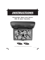
1
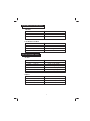
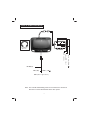
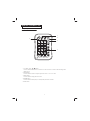
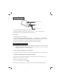
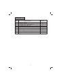
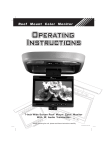
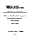
INSTRUCTIONS
15.2-inch Roof Mount Color Monitor
With IR Audio Transmitter
15.2"
16:9
Before operating the unit, please read these instructions carefully
OT01005410-200208
General Information
TABLE OF CONTENTS
General Information
W elcome
.............................................................................. 1
Precautions
........................................................................ 1
Important Notes
.................................................................... 2
Installation Guide
Precautions
............................................................................ 3
Electrical Connections
......................................................... 4
Signal Connections
............................................................ 4
T ypical Wiring Diagram .................................................... 5
Main Unit
Function K
eys
............................................................. 6
Remote Control Unit
Frequently Used Buttons
...................................................... 7
Replacement of Battery .......................................................... 8
Precautions
...................................................................... 8
Operating the Monitor
Eject / Open the Display Monitor
...................................... 8
K eeping the Display Monitor .............................................. 9
Signal Source ON / OFF ( ) ................................................. 9
Function Mode (MENU)
..................................................... 9
Door Light ON / OFF
............................................................ 9
Courtesy Light ON / OFF .................................................... 9
Accessories Supplied
Technical Specifications
........................................................... 10
........................................................... 11
System Configuration ................................................................... 12
WELCOME
Thank you for your purchase of this Roof Mount Color Monitor. Prior to operating
this unit, please read this instruction manual and retain it for future references.
PRECAUTIONS
To avoid serious electrical damage to the unit, to the car and/or to yourself, you
should follow the instructions in this manual.
* Should there be a need to replace a burnt fuse, turn off the unit and disconnect all
power supply. Use only the correct rating fuse to avoid electrical damage to the unit.
* During operation, if the unit should over-heat or malfunction, switch off the unit
and see your dealer. Do not disassemble the unit. There are no serviceable parts in
this unit.
To avoid serious injury to yourself and prevent damage to the LCD panel, please
observe the following:
* Do not drop the LCD panel or subject it to direct impact. Impact will cause
damage to the LCD panel and/or to the back light element.
* Should the LCD panel brake or leak fluid, please avoid all contact with the
unit. If you should come into contact with the leaked fluid, please wash the
affected area thoroughly with water and seek immediate medical attention.
This unit is designed using high quality electronic components and manufactured
under a stringent quality control system. This unit will provide you with numerous
hours of quality performance if utilized as specified. If need be, please follow these
maintenance procedures:
* The battery of the remote control unit has an estimated life cycle of six (6) months.
To ensure proper functionality, replace the battery on a timely manner. Once
replaced, both batteries must be new.
* Do not use any chemical solvent, cleaning agent or corrosive detergent when
wiping the display. If chemicals are used, you will cause irreversible damage to
the TFT screen. A soft, damp, lens cleaning cloth should be used to wipe the
screen of fingerprints and debris.
* Do not drop the monitor or impact it with hard objects. This may cause
permanent irreversible damage to the LCD panel and/or the back light element.
* When operating the unit, avoid contact with the LCD panel.
1
* Prevent a metal or foreign object being locked between the LCD screen and the
enclosure. Objects may impeach smooth running of the tray and may cause
electrical problems.
IMPORTANT NOTES:
* When the unit is used in conjunction with a Radio/TV tuner, please assure that
the receiver is manufactured to receive television broadcast signals that are
transmitted via terrestrial radio waves. Reception quality will change and vary
according to geographic location and climatic control.
* We strongly advise for the display screen to be installed at a location, where
the attentiveness of the driver will not be affected while driving.
* Avoid installing the monitor at a location, where it will be under direct sunlight or
a hot air vent. Operating temperature of the unit is from 32-92 degrees fahren height.
If the internal temperature of the vehicle is higher than the normal operating
temperature, please allow cool off periods for the unit.
* Install the unit at a dry location, where it is away from condensation.
* Only correct size of fasteners or installation cables should be used during
installation. Failure to do so may cause a mechanical failure and create a fire hazard.
* When in doubt, the authorized dealer should be contacted.
* To avoid electrical shock to yourself and others, do not disassemble the unit,
for there are no serviceable parts within.
* The picture quality of this LCD unit depends strictly on its installed location. To
achieve the best picture quality, adjust the brightness control or viewing angle of the
unit until the optimum level is reached.
Before installing this display system, please check that you are in compliance
with your local traffic rules and regulations
2
INSTALLATION GUIDE
Precautions:
1. This unit should be installed by a qualified service technician.
2. This product is designed to operate with a 12V DC, negative ground battery
system.
3. Disconnect the ground wire from the battery terminal prior to connecting the
unit to the electrical system.
4. The wiring from some other products or accessories might bear similar color
code as this product; however, they might be of other function. Please refer to
the electrical connection diagrams of this product prior to installing to avoid
improper connection.
5. Use proper installation and fastening materials to prevent electrical damage to
the unit.
6. Do not connect the yellow wire of this product directly to the battery terminal.
Connect the red wire of this product to the ACC of the ignition key switch.
Failure to do so may result in permanent drainage of the battery charge.
7. Only supplied accessories should be used to avoid damage to the unit during
installation.
8. Ensure that the display monitor is suitably installed at a location, such that it
will not obstruct the rear view mirror and/or the air condition vents.
9. Do not install this unit at a declining angle exceeding 30 degrees.
10. Do not install screws over the plane surface, which may affect monitor eject
or retract function.
3
ELECTRICAL CONNECTION:
AD-6869
Color Code
Black
Red
Yellow
Function
Ground
A
CC
+12V
COURTESY LIGHTS
Color Code
Black
Red
Grey
Yellow
Function
Ground
ACC
Door - Light Sensor
+12V
SIGNAL CONNECTION:
AUDIO
Color Code
Red
1 (RCA)
White 1 (RCA)
Red
2 (RCA)
White 2 (RCA)
Red
3 (RCA)
White 3 (RCA)
Function
Audio - Right (Input)
Audio - Left (Input)
Audio - Right (Input)
Audio - Left (Input)
Audio - Right (Input)
Audio - Left (Input)
VIDEO
Color Code
Yellow 1 (RCA)
Yellow 2 (RCA)
Yellow 3 (RCA)
Function
Video - In (V-IN 1)
Video - In (V-IN 2)
Video - Out (V - OUT 1)
4
TYPICAL WIRING DIAGRAMS
A (R)
13 PIN
TO MONITOR
SERIAL NO.
MADE IN TAIWAN
IN 1
V
V
AD-6869
ADAPTORS
INPUT DC-13.2V
FUSE 2A
I R Headphone
( Opt i onal )
A (L)
OUT
RED-ACC
YELLOW-BATTERY
BLACK-GND
A (L)
IN 2
A (R)
V
A (L)
A (R)
AD-6869
)
R
E
D
B
L
A
C
K
(
B
+
G
N
D
(
YELLOW ( B+)
)
)
(
A
C
C
Y
E
L
L
O
W
RED ( ACC)
BLACK ( GND )
GRAY ( Door - Li ght Sensor )
Note : The unit will automatically power off once the ACC is turned off.
Be sure to connect the Red wire to the ACC power.
5
MAIN UNIT FUNCTION KEYS
9
5
9
6
7
1
8
3 4 3
2
1¡BLCD Display
2¡BON/ OFF Button (
6¡BCourtesy Light (
7¡BRemote Sensor
)
3¡BUP/DOWN Button (UP/DOWN)
8¡BOPEN Button
4¡BMENU Button (MENU)
5¡BDoor Light ON / OFF Button(
9¡BIR
)
6
Transmitter
)
REMOTE CONTROL UNIT
Frequently used buttons:
1
CH/DISC/SET
POWER
4
1
2
3
4
5
6
7
8
9
0
MUTE
SAVE
BAND
DISP
MODE
2
MENU
3
MEMORY
VOL
SCAN
5
REP
RC-1029A
MOBILE AV REMOTE CONTROL
1. CH / DISC / SET (
/
) buttons
Use these buttons to search for TV channels or to select disc title or to select the desired settings under
MENU screen.
2. MODE button
Press this button to select the required input video source. i.e. TV / AV1 / AV2.
3. MENU button
Press this button to display the menu screen.
4. POWER button
Press this button to OPEN (ON) or CLOSE (OFF) the monitor enclosure
5.MUTE button
7
Replacement of battery
Remot e Cont r ol l er
Bat t er y
Bat t er y Hol der
1. Use a small coin to open the battery clip.
2. Remove old battery and replace it with the positive “+” sign facing upward.
3. Push battery clip into compartment until it is locked.
Precautions
1. Properly dispose of used battery.
2. Do not misuse battery by shorting the positive “+” and negative “-” terminal or put
it into fire. Overheating may cause the battery to explode and cause a fire hazard.
3. Remove the used battery from the compartment to prevent leakage.
4. To avoid accidents, prevent children from playing with the battery.
OPERATING THE MONITOR
Note: Some function modes can only be activated when the monitor is connected as an
integrated system with our range of peripherals, e.g. Radio TV Tuner, VCD/CD
Changer, DVD Player, or DVD Changer.
1. EJECT/OPEN THE DISPLAY MONITOR
To eject/open the display monitor, push & pull the open button to the desired position.
2. KEEPING THE DISPLAY MONITOR CLOSED
To prevent the LCD display from opening, pull the monitor back into the tray and
engage the monitor lock with a click.
3. SIGNAL SOURCE ON/OFF (
)
To select the input signal AV1 or AV2 by activation of ON/OFF (MODE) button.
8
Note: The key function of this monitor will change when it is installed with our range
of peripheral products. e.g. TV/Radio Tuner or Amplifier. Please refer to the
respective product manual for details.
4. FUNCTION MODE (MENU)
Press “MENU” button to activate the screen set up sequence as follows:
COLOR
¡÷
CONTRAST
¡÷
BRIGHTNESS
¡÷
TINT
COLOR: Color adjustment
CONTRAST: Contrast adjustment
BRIGHTNESS: Brightness setting
¡÷ SCREEN
MODE
Cinema
Normal
Zoom
Wide
TINT: Adjustment to color saturation
SCREEN MODE: SCREEN MODE Adjustment
Once the desired setting is selected, press the cursor key to the desired setting. If a key
is not activated within 5 seconds, this function mode will turn off.
Once the correct function is selected, press the cursor key i.e. ( or ( to the desired
setting. If no key is depressed, this function mode will turn OFF in about 5 seconds.
5. DOOR LIGHT ON/OFF (
)
Engage this switch to have the door sensor activate the doom lights.
Note: This function can be operational only when the Gray wire of the crystal doom
light assembly is connected to the door sensor.
6. COURTESY LIGHT ON/OFF (
)
Activate this switch to “ON/OFF” to activate the crystal doom light.
9
Accessories supplied
Item
1
2
3
4
5
6
7
8
9
Item Description
Metal plate
Adaptor, AD6869
Fastener screws, (Pan head B3 x 5)
Fastener screws, (B3 x 12)
Remote controller (RC-1029A)
Operating manual
Power supply cable assembly, 4P
Interconnecting cable assembly, doom light
Source Cable MD 13 pin-13pin
10
Quantity
1
1
4
2
1
1
1
1
1
TECHNICAL SPECIFICATIONS
Type
Display System
Display Format
Aspect Ratio
Resolution
Active Area
Back Light
Mechanism
Display Angle
Source
Wireless Audio
Crystal Doom Light
Operating Voltage
Operating Current
Operating Temperature
Roof Mount Color Display Monitor
15.2-inch Active Matrix Color TFT LCD
NTSC / PAL Auto Switch
409,920 pixels
16 : 9
854 (W) x 480 (H) x 3 RGB
335.6 (W) x 188.6 (H) mm
10,000 hours normal operation
Manual Open / Close
Adjustable
Horizontal: Up/Down < 110¢X
Composite video input x 2
Composite video output x 1
Audio L/R input x 1
Infrared audio transmitter (Support IR receiver
stereo head phone, L-channel: 2.3MHz /
R-channel: 2.8MHz)
Effective listening angle: 30¢X
Effective range: 4 meter
5W x 2 with door sensor connection
DC 12V
2.3A, Typical
0¢XC to 60¢XC
All specifications are subjected to change without prior notification
11
SYSEM CONFIGURATION
OPTION 1
AD-6869
Color Monitor/One Din DVD Player Digital Sound Processor Unit
Video Out
Audio Out ( L)
Audio Out (R)
12V Supply
Audio In (L)
Audio In (R)
Optical Cable
Color
Monitor
DSP Unit: DTS Sound
Processor
One din
DVD Player
IR Headphone
(Optional)
Speakers
OPTION 2
Color Monitor/TV/Radio Tuner cum Amplifier / One Din DVD Player
Video Out
12V
Supply
Audio Out(L)/(R)
Speakers /
Power Supply
9-Pin Connector
One din
DVD Player
Audio In (L)
Audio In (R)
Proprietary DIN 9-Pin Cable
Color
Monitor
TV/Radio Tuner
cum Amplifier
Remote
Control
IR Headphone
(Optional)
Antenna
OPTION 3
Color Monitor/One Din DVD Player / Pre-Amp / Power Amplifier
12V
Supply
AD-6869
Video Out
Audio Out (L)
Audio In (L)/(R)
Audio In (L)
Audio In (R)
Audio Out (R)
Optical Cable
Pre-Amp
Color
Monitor
One din
DVD Player
Supply
to Pre-Amp
Speakers
Power Amplifier
12
IR Headphone
(Optional)